MANAGERIAL DESIGN REVIEWP10232 – UAV AIRFRAME C
Daniel Graves – Project Lead
James Reepmeyer – Lead Engineer
Brian Smaszcz – Airframe Design
Alex Funiciello – Airfoil Design
Michael Hardbarger – Control Systems

Customer Needs
Key Project Goals: Airframe must be able to carry a fifteen pound payload Easy integration with measurement controls box and
different aerial imaging systems Ability to remotely control aircraft and activate payload Ability for flight communication between aircraft and
ground relay Aircraft provides twenty minutes of flight time for local
area photography Aircraft has the potential to take off and land on site Easy assembly and disassembly of the aircraft for
transportation

Lessons Learned From P09232 The aircraft’s wings sheared off shortly before
impact. The failure was determined to be from the bending stress applied to the wings during the banked turned.
After analysis, it was concluded that the main
fiberglass spar used to support the wing was not selected properly to handle the flight loading.
High bend in the wing during flight inhibited the pilot’s control of the aircraft by reducing the effectiveness of the control surfaces.
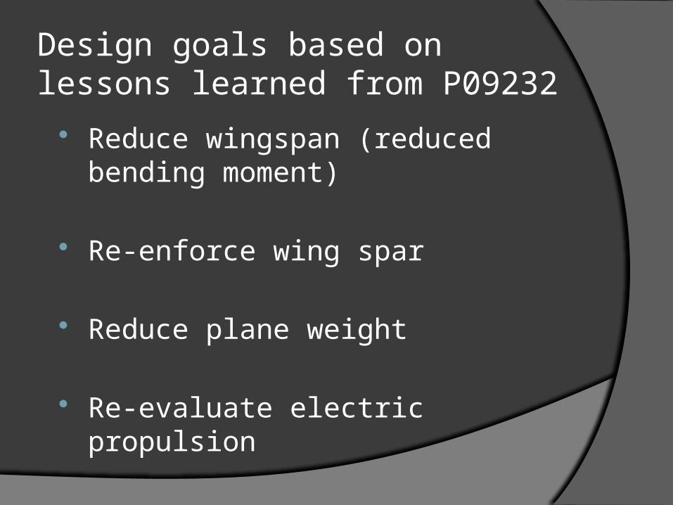
Design goals based on lessons learned from P09232
Reduce wingspan (reduced bending moment)
Re-enforce wing spar
Reduce plane weight
Re-evaluate electric propulsion

Project Status CAD model – Nearly done, ready to start creating
laser drawings Propulsion / Controls – Ready to place order on
motor and battery Landing Gear – Re-use last year’s Wing Spar – One piece spar is satisfactory; pending
confirmation from supplier on specs and availability Airfoil – Airfoil will lift plane and allow for flight control Wing box / wing design – Pending wing spar
information

Action Items

Action Items
Prove control surface equations viable with analysis
Optimum lift/drag and airspeed Optimum rate of climb with analysis Look into carbon fiber rod
cost/practicality of constructing our own

Action items
Look into carbon fiber rod cost/practicality of constructing our ownCarbon Fiber is the best option for the main sparQuality control on home-made carbon fiber spars
is very lose Maximum bending load of carbon fiber rod
Carbon Fiber rod should be sufficient to support plane weight; pending supplier specifications

Action Items
Approximation of distributed load as a point load at wing centerPrior analysis was correct, action item
dismissed Check loading analysis loading vectors
(banked turn FBD)Analysis deemed unnecessary

Action Items
Tabulate detailed calculationDetailed calculations are being updated and
documented Correct ply-wood B.O.M. error
Actual ply-wood required: 3 sheets, not 44Total ply-wood costs is approx. $73.00
Run some numbers on the loading and aero CGThe aero CG is located at the 3/4 chord of
the wing

Action Items
Notch the corner for the bottom plate of the main payload bayThe plane body has been adapted to receive the
wing mounting Provide proof airframe is stable at 40mph
Airframe can be controlled and stabilized at cruise speed using designed control surfaces
Provide proof airframe can power itself at 40 mphThe airframe requires approximately 734 watts of
power to maintain 40 mph
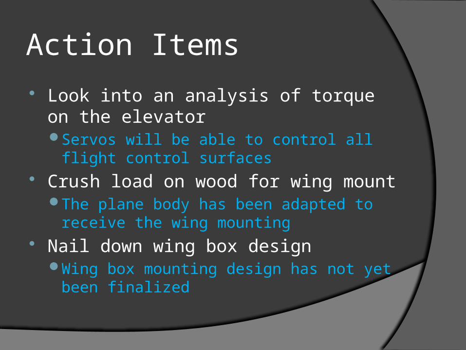
Action Items
Look into an analysis of torque on the elevatorServos will be able to control all flight control
surfaces Crush load on wood for wing mount
The plane body has been adapted to receive the wing mounting
Nail down wing box designWing box mounting design has not yet been
finalized

Action Items
Nail down tail mount designTail mount has been finalized, similar to
mount from airframe B

Customer Requirements
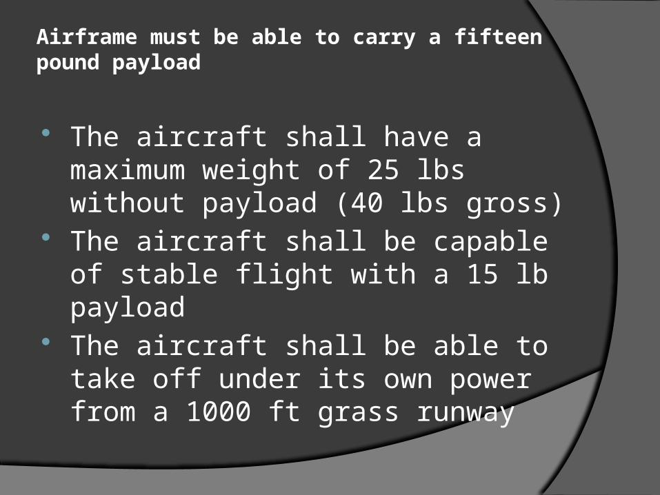
Airframe must be able to carry a fifteen pound payload
The aircraft shall have a maximum weight of 25 lbs without payload (40 lbs gross)
The aircraft shall be capable of stable flight with a 15 lb payload
The aircraft shall be able to take off under its own power from a 1000 ft grass runway

Easy integration with measurement controls box and different aerial imaging systems
The aircraft shall utilize an open architecture payload interface
The aircraft shall be capable of stable flight with a 15 lb payload
The aircraft shall provide a secure anchoring connection for the photographic instrument payload
The aircraft shall provide a secure mounting location for the flight control electronics package (P10236)
Ability to remotely control aircraft and activate payload
The aircraft shall utilize an open architecture payload interface
The aircraft shall provide a mechanical interface to the payload
The aircraft shall provide a secure anchoring connection for the photographic instrument payload
The aircraft shall provide a secure mounting location for the flight control electronics package (P10236)
Ability for flight communication between aircraft and ground relay
The aircraft shall provide a secure mounting location for the flight control electronics package (P10236 and P10231)

Aircraft provides twenty minutes of flight time for local area photography
The aircraft shall have a flight ceiling of 1000 ft The aircraft shall be able to sustain a flight of at
least 40mph in calm conditions The aircraft shall be capable of stable flight with a
15 lb payload The propulsion system shall provide uninterrupted,
constant power for at least 20 min The servos shall be of sufficient power to control
the plane’s control surfaces at speeds up to 50 mph The aircraft shall be structurally sound; no parts
shall leave the aircraft while in flight

Aircraft has the potential to take off and land on site
The aircraft shall be able to take off under its own power from a 1000 ft grass runway
The landing gear shall hold the plane at an optimal angle of attack while on the ground
The aircraft shall be able to navigate while on the ground

Easy assembly and disassembly of the aircraft for transportation
The aircraft shall be able to be transported in a motor vehicle when disassembled
The aircraft should be easy to assemble and disassemble by one person

Risk Management
https://edge.rit.edu/content/P10232/public/Risk%20Managment%20Rev%202.pdf
Recommended