1 Locksley Business Park, Montgomery Road, Belfast, BT6 9UP Tel: +44 (0)28 9070 6000 Fax: +44 (0)28 9070 6050
Email: [email protected] Website: www.wyg.com WYG Environmental and Planning (Northern Ireland) Limited. Registered in Northern Ireland: Number NI050736
Registered Office: 1 Locksley Business Park, Montgomery Road, Belfast, BT6 9UP
Dale Farm, Pennybridge Factory
Site Protection and Monitoring Plan
A111058
Dale Farm
30 October 2018
Prepared by WYG Environmental and Planning (Northern Ireland)
Limited.

Dale Farm – Pennybridge Factory, Site Protection and Monitoring Plan
A110058 30 October 2018 www.wyg.com creative minds safe hands
Document control
Document: Site Protection and Monitoring Plan (SPMP)
Project: Dale Farm, Pennybridge Factory
Client: Dale Farm
Job Number: A111058
File Origin: G:\Projects\A111\A111058\P-03 Execution\11 EP\01 Reports\03 Draft Report
Revision: Issue 1 – Draft for Client Comment
Date: 24/10/2018
Prepared by:
Shona Symon / Mark Poole
Checked by:
Mark Poole
Approved By:
-
Description of revision: Issued to Dale Farm for review and supply of additional information
Revision: Issue 2 - Final
Date: 30/10/2018
Prepared by:
Shona Symon / Mark Poole
Checked by:
Mark Poole
Approved By:
Mark Poole
Description of revision:
Revision:
Date:
Prepared by:
Checked by:
Approved By:
Description of revision:
Dale Farm – Pennybridge Factory, Site Protection and Monitoring Plan
A110058 30 October 2018 www.wyg.com creative minds safe hands
Contents.
1.0 Introduction .......................................................................................................... 4
2.0 Site Information ..................................................................................................... 5
2.1 Site Location .............................................................................................................. 5
2.2 Details of Installation .................................................................................................. 6
2.2.1 Fuel Inventory for the Site ................................................................................. 6
2.2.2 Chemical Inventory for the Site .......................................................................... 7
2.3 Site Conceptual Model ...............................................................................................10
2.3.1 Uncertainties and Assumptions in CSM ..............................................................11
3.0 CEMP Objectives .................................................................................................. 12
4.0 Environmental Monitoring Plan .............................................................................. 13
4.1 Objectives of the Monitoring Programme ....................................................................13
4.1.1 Objectives of the Environmental Monitoring Programme .....................................13
4.1.2 Objectives of the Infrastructure Monitoring Programme ......................................13
4.2 Environmental Monitoring Infrastructure .....................................................................14
4.2.1 Discharge Monitoring Infrastructure ..................................................................14
4.2.2 Groundwater Monitoring Infrastructure..............................................................14
4.2.3 Soil Testing......................................................................................................14
4.2.4 Procedure for the Inspection and Maintenance of Environmental Monitoring
Infrastructure ..................................................................................................15
4.3 Environmental Monitoring Schedule ............................................................................15
4.3.1 Discharge ........................................................................................................15
4.4 Summary Sampling Protocols .....................................................................................16
4.4.1 Discharge to Surface Water ..............................................................................17
4.4.2 Groundwater ...................................................................................................17
4.4.3 Soil .................................................................................................................17
Dale Farm – Pennybridge Factory, Site Protection and Monitoring Plan
A110058 30 October 2018 www.wyg.com creative minds safe hands
Laboratory Accreditation / Quality Assurance and Quality Control ...........................................17
4.4.4 Laboratory Accreditation ...................................................................................17
4.4.5 Quality Control .................................................................................................17
4.5 Sampling Personnel ...................................................................................................18
4.6 Infrastructure Monitoring Programme .........................................................................18
4.6.1 Personnel ........................................................................................................19
5.0 Assessment and Reporting Procedures ................................................................... 20
5.1 Assessment Procedure ...............................................................................................20
5.2 Reporting Procedure ..................................................................................................20
5.3 Recording and Data Management ...............................................................................20
6.0 Planned Preventative Maintenance Programme ....................................................... 21
7.0 Figures................................................................................................................ 22
Figure 1 Site Layout and Monitoring Location Plan ..........................................................23
Figure 2 Site Drainage Plan ............................................................................................24
8.0 Appendices .......................................................................................................... 25
Appendix A: Dale Farm Environmental Monitoring, Inspection, and Reporting Procedure .........26
Appendix B: Previous SPMP (2014) ......................................................................................27
Appendix C: Site Investigation Reports .................................................................................28
Appendix D: Dale Farm Quality Assurance ............................................................................29
Appendix E: Laboratory Accreditation ...................................................................................30
Appendix F: Data Recording Sheets .....................................................................................31

Dale Farm – Pennybridge Factory, Site Protection and Monitoring Plan
www.wyg.com creative minds safe hands 4
1.0 Introduction
WYG Environment & Planning Ltd (WYG) was commissioned by Dale Farm in October 2018 to prepare
an updated Site Protection and Monitoring Programme (SPMP) for its milk and juice manufacturing
processing facility - Pennybridge (the ‘installation’).
The Site is regulated under the Pollution Prevention and Control (Industrial Emissions) Regulations
(Northern Ireland) 2013 (the PPC Regulations). The original Environmental Permit (EP) for the Site
was issued on 01 July 2006, Reference P0093/05A. The EP was varied on 01 August 2011 and as a
result is now reference P00093/05A/V1.
The previous SPMP review was prepared in July 2016 by way of a review of the Site Condition Report
in pursuance of Condition 4.1.7 of IPPC Permit reference P0093/05A.
This SPMP has been prepared in accordance with the Northern Ireland Environment Agency Guidance
H7 – Guidance on the Protection of Land Under the PPC Regime: Application Site Reporting and Site
Protection and Monitoring Programme - Site Report Guidance and template for applicants and
operators – Version 1, dated March 2004.

Dale Farm – Pennybridge Factory, Site Protection and Monitoring Plan
www.wyg.com creative minds safe hands 5
2.0 Site Information
2.1 Site Location
The Site is located within an industrial setting approximately 1.6km south east of Ballymena town
centre and can be accessed via the Larne Road or the Limavady Road off Ballee Road East, dual
carriageway. The site is centred at grid reference 311663 401811.
Inset 1 Site Location Plan
The Site is surrounded to the north by light industrial and commercial units, to the east by
Pennybridge Industrial Estate along with several light industrial and commercial units, to the west
by scrub land and recreational facilities, and to the south by scrub land and residential properties. A
fuel station and heating oil supplier is located approximately 10m from the eastern boundary of the
Site.

Dale Farm – Pennybridge Factory, Site Protection and Monitoring Plan
www.wyg.com creative minds safe hands 6
2.2 Details of Installation
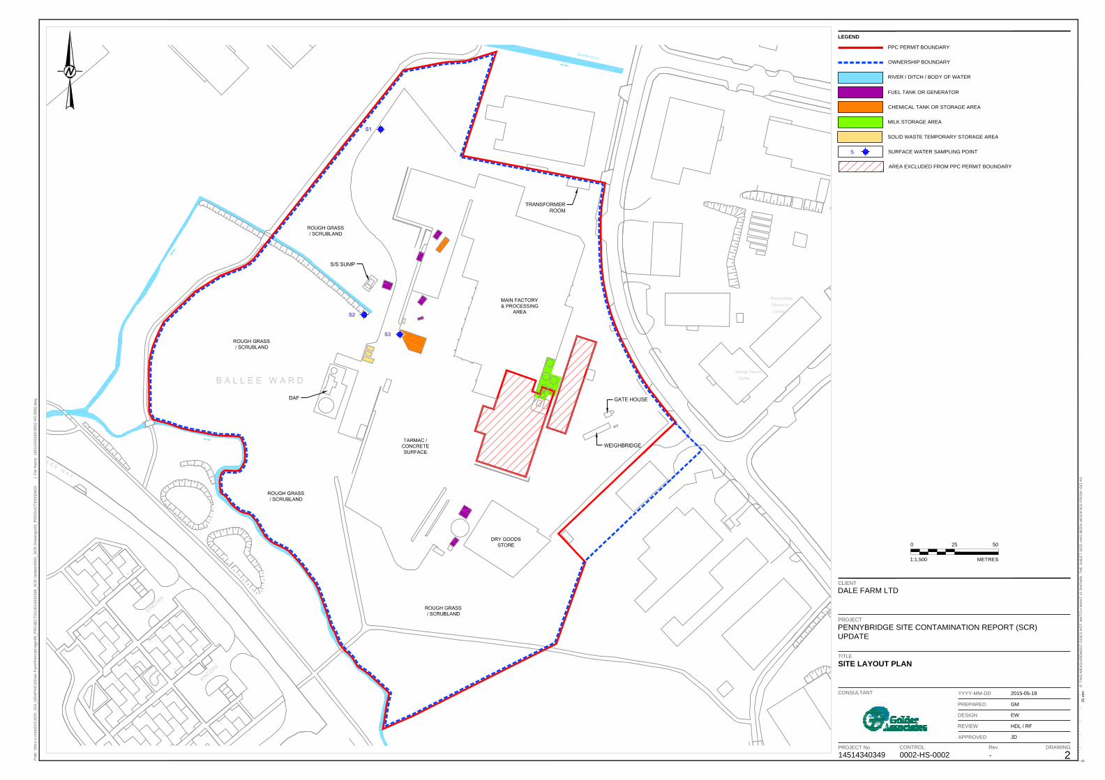
The site layout is presented on Figure 1 which shows the Permit boundary and main operational
areas. Most of the Site footprint is covered by buildings and hardstanding (concrete/bitmac/asphalt)
that appeared to be in good condition during the site visit on 19th October 2018. A section of ground
around the perimeter of the factory to the north west, west and south west is scrub land which is
being managed for potential ecological development.
Raw materials typically stored at the site are presented on Table 2.1.
Table 2.1 Raw Materials and Liquid Product Storage Details
Material Location Quantity and Storage Details
Delivery Details
Milk
Intake/Reception Area in the central
portion of the Site (raw milk)
4No. 100,000L raw Storage Silos
Pumped via above ground pipework
Rear of technical
building in eastern portion of the site (processed milk)
3No. 1 ×10,0000L and 2 × 10,000L storage Pumped via above
ground pipework
Intake/Reception
Area in the central portion of the Site (processed milk)
2No. 40,000L Storage Silos
Pumped via above ground pipework
Juice Concentrate Western portion of
the site adjacent to DAF plant area
6No. 1,000L IBC Delivered to site in IBC
2.2.1 Fuel Inventory for the Site
Fuels are stored in purpose built secure storage areas located across the installation area. Table 2.2
details the main fuels stored on Site and their respective storage locations.

Dale Farm – Pennybridge Factory, Site Protection and Monitoring Plan
www.wyg.com creative minds safe hands 7
Table 2.2 Fuel Inventory for the Site
Material Location Quantity and Storage Details Delivery Details
Liquefied
petroleum Gas
(LPG)
North of the site 1No. 1200L tank Fill point and above
ground pipework
Diesel
Adjacent to the
boiler house in the
north of the Site
1No. 10,000 L plastic (35 sec gas oil)
tank which has aboveground
pipework extending to the generator
in 110% brick bund with external
bund fill points fitted with catch trays
Fill point and above
ground pipework
Adjacent to
generator
1000l day tank for the emergency
generator
Fill point and above
ground pipework
North west of the
Dry Goods Store 1No. 1,000L plastic bunded tank
Tank is directly filled
from delivery tanker
Waste oil Service area 1000l tank Filled manually
Hydraulic,
lubricating, and
transformer oil
Within a plant room
in the service area
close to the boiler
house
205 L steel barrels, or 20 to 25 L
plastic drums. The barrels are stored
on portable plastic bunds and either
pumped or manually transported to
the required locations
Delivered in
manufacturer containers
oils and greases
Within the
workshop in the
service area
<5L drums stored on concrete floor Delivered in
manufacturer containers
2.2.2 Chemical Inventory for the Site
The two main chemical storage areas are located to the west of the main factory. One area is located
adjacent to the mains water tank and the other adjacent to the DAF plant.
These compounds contain a variety of chemicals in 1,000 litre IBCs, 25kg plastic bags on pallets, 20-
41kg plastic drums. Any spillages that do occur in the chemical compound are pumped direct to the
ETP for treatment prior to discharge. Table 2.3 details the main chemicals stored on Site and their
respective storage locations.

Dale Farm – Pennybridge Factory, Site Protection and Monitoring Plan
www.wyg.com creative minds safe hands 8
Table 2.3 Chemical Inventory
Material Location Quantity and Storage
Details Delivery Details
Cleaning in Place (CIP)
detergent (sodium
hydroxide)
CIP area located in
northern portion of the
site
10,000 litres capacity Bulk delivery
CIP acid (nitric and
phosphoric acid)
Within the main
chemical compound and
between two finished
milk silos beside the
intake area.
Stored in powder form
in 25 kg bags or 41 kg
plastic drums.
4 No. 1000L IBC’s
Delivered in
manufacturer packaging
Acid sterilant (peracetic
acid)
Within the glass bottling
hall next to the
salt/water softener.
Small quantities at
strategic locations
around the plant
2No. 1000l IBC’s
Delivered in
manufacturer containers
/ packaging
Multi-purpose cleaning
solution for manual
cleaning (alkaline)
Within the secure
chemical compound
situated adjacent to the
mains water tank. The
compound floor is
concrete hard standing.
Generally stored on
portable plastic bunded
tanks (Intermediate Bulk
Containers “IBCs”) or in
20 or 25 L plastic drums
on pallets.
Delivered in
manufacturer containers
/ packaging
Disinfectant spray
Within the main
chemical compound in
the central portion of
the site
50L
Delivered in
manufacturer containers
/ packaging
High foaming liquid
detergent
Within the main
chemical compound in
the central portion of
the site
800L in 25L drums
Delivered in
manufacturer containers
/ packaging
Line lubrication (ionic
and synthetic) oils
Within the main
chemical compound in
the central portion of
the site
40L Delivered in
manufacturer containers
/ packaging
Welding/cutting/soldering Within the engineering 1 No. 52kg Tank Delivered in

Dale Farm – Pennybridge Factory, Site Protection and Monitoring Plan
www.wyg.com creative minds safe hands 9
gases compound in the
southern portion of the
site
manufacturer containers
/ packaging
Refrigerant (ammonia,
R404)
Services block (between
the boiler house and
fitter workshop).
1 No. 52kg Tanks Delivered to Site in 52
kg tanks
Engineering cleaning
solvents
Within the main
chemical compound in
the central portion of
the site
Generally stored on
portable plastic bunded
tanks (Intermediate Bulk
Containers “IBCs”) or in
20 or 25 L plastic drums
on pallets.
Delivered in
manufacturer containers
/ packaging
Hot melt glue (small
quantities)
Dry Goods Store located
in the southern portion
of the site
40Kg
Delivered in
manufacturer containers
/ packaging
Printing ink (small
quantities)
Dry Goods Store located
in the southern portion
of the site
100L Delivered in
manufacturer containers
/ packaging
Granular water softener
salt
Boiler House in Northern
portion of the site
1m3 pallet packaged in
25kg bags
Delivered in
manufacturer containers
/ packaging
Sodium hypochlorite
Within the main
chemical compound in
the central portion of
the site
25L drum typical
quantities 20No. drums
Delivered in
manufacturer containers
/ packaging
Corrosion and scale
inhibitors, and biocides
(treatment of cooling and
boiler water)
Boiler House in Northern
portion of the site 200L
DAF Chemicals (Sodium
hydroxide, Sulphuric
Acid, Polyelectrolyte and
flocculent (PAC)
DAF plant in eastern
portion of the site. 4No. 1000L IBC’s
Delivered in
manufacturer containers
/ packaging

Dale Farm – Pennybridge Factory, Site Protection and Monitoring Plan
www.wyg.com creative minds safe hands 10
2.3 Site Conceptual Model
This section provides a summary of the original Site Conceptual Model.
Table 2.3 Original Site Conceptual Model
Aspect Details
Geology
Made Ground – Made Ground is expected across much of the site due to
historic site development activities.
Drift – Glaciofluvial sands, gravels and boulders
Solid – Lower Basalt Formation
Hydrogeology
Site underlain by a locally important aquifer with limited abstraction potential and
moderate to low hydraulic conductivity. However, the soils have a high leaching potential.
The overlying sands and gravels may not provide significant protection to the underlying
aquifer.
Groundwater was encountered in 1No borehole during drilling by Glover Site Investigations
in September 2009. The borehole (BH01) is located beneath the main building onsite and
water was encountered at 2.3mbgl within glaciofluvial deposits
Surface Water Features
The Site is located within the catchment of the Deerfin Burn, which drains to the Braid
River. The Deerfin Burn flows in a westerly direction approximately 75m to the north and
75m west of the Pennybridge site. The Deerfin Burn flows in a westerly direction before
joining the Braid River which in turn flows into the River Main before flowing into Lough
Neagh.
The Deerfin Burn has a chemical classification of moderate to high and a biological
classification of moderate to good
Ecological Receptors No ecologically sensitive areas within 500m of the site.
Summary of Receptors
(Pathways)
Land (spills and leaks to ground);
Locally important aquifer (leaching from soils, and percolation through
permeable ground);
Deerfin Burn
Activities Identified
with Reasonable
Possibility of Future
Pollution Occurring
Delivery and storage of milk;
Storage of cream, buttermilk and skimmed milk
Delivery and storage of Concentrated Juice Products
Delivery of bulk caustic
Delivery use and storage of diesel
Storage of waste oil
Potential leakage from the sludge into the hardstanding and surface drainage
areas during transfer for disposal
Potential leakage from the effluent drainage system
Land Pollution History
& Main Pollution
Incidents
Agricultural use
The current records for pollution incident reporting at the Site indicate that there have
been no incidents
Dale Farm – Pennybridge Factory, Site Protection and Monitoring Plan
www.wyg.com creative minds safe hands 11
Contamination
Identified in Previous
Investigations
GLOVERS SITE INVESTIGATIONS (2009)
Glover Site Investigations completed an intrusive investigation at the Site in September
2009. Seven boreholes were sunk with one installation. Three small disturbed soil samples
were taken and sent for laboratory analysis. All soil sample results were recorded below
relevant published human health screening criteria for commercial land use. Eluate results
(from the Waste Acceptance Criteria (WAC) tests) have been compared to published water
quality standards (either surface water or drinking water, whichever is lowest) and all
results were found to be below the screening levels. The full Site investigation report is
provided at Appendix B.
CAUSEWAY GEOTECH (2014)
An intrusive investigation was carried out by Causeway Geotech in September 2014 in the
location of the newly constructed DAF plant. 4No. disturbed soil samples were submitted
for laboratory analysis (one from each borehole). All soil sample results were recorded
below relevant published human health screening criteria for commercial land use. Eluate
results (WAC tests) have been compared to published water quality standards (either
surface water or drinking water, whichever is most conservative). The sample from BH03,
at a depth of 0.5 m, contains copper and nickel that leaches at concentrations marginally
greater than the water quality standards (copper: 0.0062 mg/l compared to the 0.06 mg/l
standard; and nickel 0.00235 mg/l compared to the 0.002 mg/l standard). These
concentrations are unlikely to be a concern. All other concentrations are lower than the
water quality standards. The full Site investigation report is provided at Appendix B.
WYG (2016)
A groundwater ‘grab’ sample was collected from an on-site borewell located adjacent tm
the Chemical storage area (Drawing 2) on 25 May 2016 for analysis to facilitate the SCR
update. No information is held on the installation details or date of installation for this
borehole other than that it was installed in 2010 as part of a groundwater abstraction
assessment.
The groundwater sample was analysed for a range of potential contaminants including
metals, speciated total petroleum hydrocarbons, speciated polycyclic aromatic
hydrocarbons, cyanide and pH. All results were recorded below UK DWS / relevant
guidance limits excluding several Poly Aromatic Hydrocarbons (Phenanthrene,
Fluoranthene, Pyrene, Benzo(a)anthracene, Chrysene and Benzo(bk)fluoranthene) which
were present in small quantities. These contaminants are associated with petroleum-based
products and potentially originate from fuel. The full lab report is found at Appendix B.
2.3.1 Uncertainties and Assumptions in CSM
The following uncertainties and assumptions are implicit in the CSM described:
• Thickness and composition of shallow ground conditions across the site are unknown. It is
assumed that much of the developed portions of the site are underlain by Made Ground which
is further underlain by Boulder Clay. A geotechnical site investigation was carried out by
Causeway Geotech in 2014. The site investigation information is limited to the footprint of the
DAF plant located in the eastern portion of the site. In the eastern portion of the site, firm to
Dale Farm – Pennybridge Factory, Site Protection and Monitoring Plan
www.wyg.com creative minds safe hands 12
stiff clay was encountered from approximately 0.2mbgl. Boreholes were terminated between
2.4 and 2.6mbgl is suspected weathered bedrock;
• The depth to groundwater is not known across the site, although no water strikes were
encountered during the Causeway Geotech site investigation;
• Pollution incidents may have occurred from before the current factory existed.
3.0 CEMP Objectives
The objectives of this report are:
• To design a monitoring programme for the installation to:
o Monitor the effectiveness of the pollution prevention infrastructure and provide early
warning of any release of polluting substances to the environment;
o Monitor the effectiveness of the pollution prevention infrastructure and provide early
warning of any release of polluting substances to ground or groundwater;
o To collect data on the condition of the ground at the installation to assist in the permit
surrender process;
• To review and if necessary amend the inspection, testing and maintenance programme for
pollution prevention infrastructure at the installation to ensure their continued integrity.

Dale Farm – Pennybridge Factory, Site Protection and Monitoring Plan
www.wyg.com creative minds safe hands 13
4.0 Environmental Monitoring Plan
4.1 Objectives of the Monitoring Programme
4.1.1 Objectives of the Environmental Monitoring Programme
The objectives of monitoring discharge, groundwater, air, and soil at the installation are as follows:
• To monitor the effectiveness of infrastructure and management procedures and provide a
warning of loss of contaminants;
• To assist at Permit Surrender by;
o Determining the movement of pollutants off the site via discharge at the installation;
o Determining the movement of pollutants within groundwater in the vicinity of the
effluent treatment plant at the installation;
o Determine land quality at the installation to assist in the permit surrender process,
and;
o Providing data on long term trends.
4.1.2 Objectives of the Infrastructure Monitoring Programme
The purpose of the infrastructure monitoring programme is to demonstrate the effectiveness of
pollution prevention measures at the site throughout the life of the permit.
Historical samples have been taken from the environmental monitoring infrastructure which includes
discharge monitoring points from which samples are collected prior to being discharged to the River
Maine.
The existing discharge monitoring infrastructure within the permitted area is suitable for both the
requirements of the SPMP and the monitoring requirements of the PPC Permit.
The substances that may potentially pollute the groundwater are expected to be detectible in the
proposed groundwater monitoring boreholes.

Dale Farm – Pennybridge Factory, Site Protection and Monitoring Plan
www.wyg.com creative minds safe hands 14
4.2 Environmental Monitoring Infrastructure
4.2.1 Discharge Monitoring Infrastructure
Figure 1 shows the location of the discharge monitoring points at the installation in relation to the
location of the sources of contamination at the site. A site drainage plan has been presented on
Figure 2.
Discharge monitoring point detail is summarised on Table 4.1.
Table 4.1 Discharge Monitoring Locations
Monitoring
Location Ref Sample Location
Approximate Grid
Reference (eastings,
northings)
W1 Storm water discharge to unnamed tributary of the Deerfin Burn 311538, 401941
W2 Storm water runoff from lorry park to unnamed tributary of the
Deerfin Burn 311524, 401827
W3 Storm discharge from service area to unnamed tributary of Deerfin
burn 311524, 401827
W5 Storm discharge from technical centre area to unnamed tributary
of Deerfin burn 311668, 401812
S1 Discharge to Sewer 311543, 401818
4.2.2 Groundwater Monitoring Infrastructure
There are currently no shallow groundwater monitoring boreholes available for sampling at the site.
It is proposed that shallow groundwater monitoring boreholes will be included in the works package
for future geotechnical site investigations at the site.
4.2.3 Soil Testing
At present it is not proposed to undertake any on-going soil monitoring as part of the SPMP. Soil
samples will be retrieved and analysed during site investigations at the site in the future.
Soil samples will be analysed for the following parameters -
• Total petroleum hydrocarbons
• Heavy fuel oil, diesel range organics
• PAH, PTE’s and nitrogen compounds
• TN, NO3, NH4 and pH
These will form the baseline data for the site.

Dale Farm – Pennybridge Factory, Site Protection and Monitoring Plan
www.wyg.com creative minds safe hands 15
4.2.4 Procedure for the Inspection and Maintenance of Environmental Monitoring
Infrastructure
Discharge
Storm Drains - A visual inspection of the drainage system will be carried out quarterly. Any drains,
which are reported to be damaged, or not free flowing will be cleaned, and further inspection
completed if necessary.
Hard standing - A visual inspection of the external yard will be carried out monthly. Any flooring
which is reported to be in a poor condition will be repaired.
Chemical bunds - Various areas around the site as identified in the ASR, these will be checked
monthly.
Interceptor - Checked once per quarter.
4.3 Environmental Monitoring Schedule
4.3.1 Discharge
Discharge is routinely monitored at the site at multiple discharge locations at the site. Discharge
monitoring locations are presented on Figure 1. The discharge monitoring frequency has been
presented on Table 4.3, and the parameters to be analysed at each location, and their respective
consented limits, are presented on Table 4.4.
Table 4.3 Discharge Water Monitoring Frequency
Release Point Parameter PPC Requirement Dale Farm Procedure
W1, W2, W3 &
W5
pH Quarterly spot sample Monthly spot sample
Suspended Solids Quarterly spot sample Monthly spot sample
BOD Quarterly spot sample Monthly spot sample
VOG Weekly spot sample Weekly spot sample
Temperature Weekly spot sample Weekly spot sample
S1
pH Monthly spot sample Monthly spot sample
COD Monthly spot sample Monthly spot sample
Suspended Solids Monthly spot sample Monthly spot sample
Temperature Daily Daily
Daily Maximum Volume Daily Daily
Note: COD – Chemical Oxygen Demand. BOD – Biological Oxygen Demand. VOG - Visible Oil and Grease

Dale Farm – Pennybridge Factory, Site Protection and Monitoring Plan
www.wyg.com creative minds safe hands 16
Table 4.4 Consent limits for permitted discharge locations
Release Point Parameter Value
W1, W2, W3 & W5
pH 6-9
Suspended Solids 50 mg/l
BOD 50 mg/l
VOG None
Temperature 25oC
S1
pH 5 - 10
COD 4,000 mg/l
Suspended Solids 800 mg/l
Temperature 45oC
Daily Maximum Volume 550m3
Note: COD – Chemical Oxygen Demand. SS – Suspended Solids. BOD – Biological Oxygen Demand. VOG = Visible Oil
and Grease
An emergency monitoring plan will be enacted following:
• An incident at the installation resulting in an emission to land;
• Pollution identified from environmental monitoring during the operation of the installation or
increasing from reference data levels; or,
• If reference data shows pollution that is not attributed to non-permitted sources.
The emergency monitoring plan will include an increased frequency of monitoring to facilitate
identifying the source and extent of any pollution and to determine whether remediation is required
under the PPC Regulations.
4.4 Summary Sampling Protocols
This section provides a summary of the sampling protocols in place at the site, which have also been
presented in the original SPMP prepared for the site. A full copy of the site Environmental Monitoring

Dale Farm – Pennybridge Factory, Site Protection and Monitoring Plan
www.wyg.com creative minds safe hands 17
Procedures have been provided at Appendix A, and a copy of the original SPMP prepared for the site
has been presented at Appendix B.
4.4.1 Discharge to Surface Water
Surface water will be collected from the points presented on Figure 1. Each sample will be collected
directly from the sampling point using clean sampling vessels provided by the laboratory.
4.4.2 Groundwater
Since groundwater monitoring locations are currently unavailable at the site, a groundwater sampling
procedure will be incorporated into the Environmental Monitoring Procedures document when
appropriate.
4.4.3 Soil
When soil sampling takes place, soil samples will be collected by a qualified experienced site
investigation engineer. All samples will be collected as un-disturbed samples from a window sample
tube. The samples will be logged and stored as appropriate prior to being sent for analysis at an
accredited lab.
Laboratory Accreditation / Quality Assurance and Quality Control
4.4.4 Laboratory Accreditation
All laboratory analysis should be completed at a UKAS (or equivalent) accredited laboratory. The
current supplier to Dromona is McQuillan Envirocare Ltd. A copy of the laboratory accreditation has
been provided at Appendix E. It is noted that the accreditation status of McQuillan Envriocare is
renewed annually on the 4th September. Up to date accreditation certificates should requested
annually post 4th September annually for as long as McQuillan Envirocare supply analytical services
to Dale Farm.
4.4.5 Quality Control
Under the conditions of laboratory accreditation, accredited laboratories have robust quality
assurance and quality control procedures.

Dale Farm – Pennybridge Factory, Site Protection and Monitoring Plan
www.wyg.com creative minds safe hands 18
4.5 Sampling Personnel
Personnel responsible for sampling, maintenance and inspection will be trained in environmental
monitoring to an appropriate level to ensure compliance with the quality assurance and quality control
plan. A copy of Dale Farm’s ISO14001 QA certificate has been provided at Appendix D.
4.6 Infrastructure Monitoring Programme
In addition to laboratory analysis of surface water samples, routine inspections are carried on
infrastructure at the site which is considered to present potential sources of pollution. Site
infrastructure monitoring locations and data recording procedures are presented on Table 4.7.
Table 4.7 Infrastructure Monitoring Schedule
Feature Inspection Detail
Diesel fuel delivery Checks are made at each delivery, all suppliers are trained in procedures and visual checks are
made before, during and after transfer of diesel. Tank bunds will be inspected every month
Diesel fuel storage Tank bunds will be checked each month, level gauges are fitted
Delivery of bulk
milk products
Bulk products will only be transferred when personnel are present and a spill kit available. The
tanker will be inspected prior to filling or despatch.
Despatch of bulk
milk products
Bulk products will only be transferred when personnel are present and a spill kit available. The
tanker will be inspected prior to filling or despatch.
Effluent treatment
plant tanks
A visual inspection of the tanks will be carried out monthly. Any tanks which is reported to be
in a poor condition will be repaired
Trade effluent
drains
A visual inspection of the drainage system will be carried out quarterly. Any drains, which is
reported to be damaged, or not free flowing will be cleaned, and further inspection completed
if necessary.
Storm drains A visual inspection of the drainage system will be carried out quarterly. Any drains, which are
reported to be damaged, or not free flowing will be cleaned, and further inspection completed
if necessary.
Internal flooring A visual inspection of the internal flooring will be carried out monthly. Any flooring which is
reported to be in a poor condition will be repaired
hardstanding A visual inspection of the external yard will be carried out monthly. Any flooring which is
reported to be in a poor condition will be repaired
Chemical bunds Various areas around the site as identified in the ASR, these will be checked monthly
Milk storage Milk is stored in 10 external tanks, 5 raw milk and 5processed milk. The tanks are visually
inspected prior to filling, all tanks have high level alarms and are checked annually
Waste oil storage The waste oil storage is located in the oil store and is on hard standing, the tank is manually
filled and inspected on a monthly basis

Dale Farm – Pennybridge Factory, Site Protection and Monitoring Plan
www.wyg.com creative minds safe hands 19
4.6.1 Personnel
Personnel responsible for the inspection, testing and maintenance of pollution prevention
infrastructure are trained to an appropriate level to ensure compliance with the Infrastructure
Monitoring. Personnel training records are stored on a training matrix maintained by HR.

Dale Farm – Pennybridge Factory, Site Protection and Monitoring Plan
www.wyg.com creative minds safe hands 20
5.0 Assessment and Reporting Procedures
5.1 Assessment Procedure
The Pennybridge Assessment Procedure has been presented at Appendix A. In summary, checklists
for the inspection and recording of fixed bunds, hard surfacing in relevant areas and maintenance
will be kept on site. The inspections will be primarily visual to identify any signs of corrosion, cracks
or other damage. Should any damage be identified that could affect the integrity of the bunds this
will be checked through water testing. Damaged hard standing will be sealed and repaired.
The effluent drainage system will be visually checked every 3 months to ensure manholes are clear
and free flowing. The system will be maintained in good working order. Manual inspection of the
storm drains will be made every month. Any suspected leaks would be investigated, and remedial
action taken as necessary. The site drainage plan will be maintained, and any changes made to the
drainage system incorporated.
5.2 Reporting Procedure
Summaries of the monitoring data will be sent to the NIEA on the 31st of January each year in an
Annual Report which includes the results of the data assessment, and any recommendations for
amendments to the Monitoring Programme.
5.3 Recording and Data Management
Inspection and assessment records of all of the above will be maintained and stored on site.
Records of the infrastructure monitoring will be retained at the installation for a minimum period of
3 years. The SPMP will be maintained with regular reviews completed at least every 2yrs. The results
of the review and any proposed changes will be discussed with the regulator.

Dale Farm – Pennybridge Factory, Site Protection and Monitoring Plan
www.wyg.com creative minds safe hands 21
6.0 Planned Preventative Maintenance Programme
A Planned Preventative Maintenance Programme (PPM) is in place at the Site. The PPM programme
is computerised and is in place to ensure that all associated maintenance is recorded and completed
at a frequency appropriate for maintenance and inspection to prevent leaks, spillages and
breakdowns. There is a register of materials storage locations as part of the materials handling
procedure which is maintained by the Environmental Manager. The results of all inspections are
recorded in the installation log book.
The original ASCR stated that there is no EMS on site as yet, however the Site has implemented an
Environmental Management System (EMS) to the external standard BS EN ISO 14001. A copy of the
certification is provided at Appendix D.

Dale Farm – Pennybridge Factory, Site Protection and Monitoring Plan
www.wyg.com creative minds safe hands 22
7.0 Figures

Dale Farm – Pennybridge Factory, Site Protection and Monitoring Plan
www.wyg.com creative minds safe hands 23
Figure 1 Site Layout and Monitoring Location Plan
PENNYBRIDGE SITE CONTAMINATION REPORT (SCR)UPDATE
DALE FARM LTD
CONSULTANT
DESIGN
PREPARED
REVIEW
APPROVED
YYYY-MM-DD
TITLE
PROJECT No. Rev.
PROJECT
CLIENT
Path
: \\b
fs1-
s-m
ain0
1\C
ADD
_GIS
_GR
APH
ICS\
Dal
e Fa
rm\P
enny
brid
ge\9
9_PR
OJE
CTS
\145
1434
0349
_SC
R U
pdat
e\00
01_S
CR
Dra
win
gs\0
2_PR
OD
UC
TIO
N\D
WG
\ |
File
Nam
e: 1
4514
3403
49-0
002-
HS-
0002
.dw
g
025
mm
IF T
HIS
MEA
SUR
EMEN
T D
OES
NO
T M
ATC
H W
HAT
IS S
HO
WN
, TH
E SH
EET
SIZE
HAS
BEE
N M
OD
IFIE
D F
RO
M: I
SO A
3
14514340349CONTROL0002-HS-0002
DRAWING
2-
2015-05-18
GM
EW
HDL / RF
JD
SITE LAYOUT PLAN
1:1,500
0 25 50
METRES
PPC PERMIT BOUNDARY
OWNERSHIP BOUNDARY
RIVER / DITCH / BODY OF WATER
FUEL TANK OR GENERATOR
CHEMICAL TANK OR STORAGE AREA
LEGEND
MILK STORAGE AREA
SOLID WASTE TEMPORARY STORAGE AREA
SURFACE WATER SAMPLING POINTS
AREA EXCLUDED FROM PPC PERMIT BOUNDARY

Dale Farm – Pennybridge Factory, Site Protection and Monitoring Plan
www.wyg.com creative minds safe hands 24
Figure 2 Site Drainage Plan

0
.4
m
*
0.9m* Ï150
0.7m* Ï150
0.7m* Ï150
0
.1
5
m
*
1
.
6
5
m
*
1
.
6
m
*
1
.
6
m
*
Ï
2
2
5
1
.6
m
*
1
.
1
m
*
Ï
3
0
0
1
.
7
m
*
1.7m* Ï750
1
.
6
5
m
*
2
.
0
5
m
*
1
.
6
m
*
1.2
m
*
1
.
0
5
m
*
1
.2
m
*
1
.0
5
m
*
1
.
1
5
m
*
1
.2
m
*
1
.
1
m
*
0
.2
m
* Ï
1
5
0
0.6m* Ï100
0.7m* Ï100
1
.
5
m
*
Ï
1
5
0
1.55m
*
1
.5
m
*
1.3m
*
1.3m* Ï150
1
.5
m
*
1
.
3
m
*
1
.
6
m
*
Ï
1
5
0
1.6m* Ï150
1.5m* Ï150
0
.2
m
*
0.2m* Ï100
1
.
2
m
*
1.2m* Ï150
0
.
3
m
*
0
.
7
m
*
Ï
2
2
5
0
.
7
m
*
0
.
4
m
*
1
.
6
5
m
*
1
.
5
m
*
Ï
1
0
0
0
.8
5
m
*
0
.
4
m
*
Ï
2
2
5
0
.9
5
m
*
0
.2
m
*
0
.
9
m
*
1
.
1
m
*
Ï
2
2
5
0
.
1
5
m
*
1.0m* Ï150
1
.2
m
*
1.0m* Ï1501
.0
m
*
1
.0
5
m
*
0.6m*
0
.
7
5
m
*
0
.
7
m
*
0
.6
m
*
0
.2
m
*
Ï
1
0
0
0
.
2
m
*
0
.
3
m
*
0
.
3
5
m
*
0
.
7
m
*
0
.
2
5
m
*
Ï
1
5
0
0
.
2
5
m
*
1
.
4
m
*
1
.4
m
*
1
.
5
m
*
Ï
3
0
0
1
.
4
5
m
*
1
.0
m
1.1m
*
1.0m
*
1
.0
m
*
0
.
9
5
m
*
1
.0
m
*
0
.6
m
*
1
.
8
m
*
1
.
8
m
*
0
.
4
m
*
0.4
m
*
0.65m* Ï150
0.65m* Ï150
1
.
0
m
*
1
.
0
m
*
0.15m
*
1
.
0
m
*
0
.
6
m
*
0
.
3
m
*
0.8m* Ï100
0
.
9
m
*
0.1
5m
*
0.3m* Ï100
0.35m* Ï100
0.7m* Ï100
0
.
8
5
m
*
0
.8
m
*
0.6m* Ï100
1
.1
m
*
0.9m* Ï100
Ï
1
0
0
0
.
9
m
*
0.5m* Ï100
0.5m* Ï150
1.05m* Ï150
0.15m*
0.4m* Ï100
0.6m* Ï100
0.6m* Ï100
1
.
5
5
m
*
Ï
3
0
0
1
.5
5
m
*
Ï
3
0
0
1
.
9
m
*
2
2
5
Ï
0
.
2
m
*
0.2m
*
0
.
2
m
*
0
.
6
m
1
.
7
m
*
0.1m*
1
.
8
5
m
*
0
.5
m
*
1
.
0
m
*
1.3m* Ï150
1
.
5
m
*
0
.
6
m
*
0
.6
m
Ï
1
5
0
0
.
1
m
*
Ï
1
5
0
0
.
1
5
m
*
Ï
225
0
.
9
m
*
Ï
2
2
5
Ï
1
5
0
Ï
1
5
0
Ï
3
0
0
Ï
2
2
5
Ï
1
5
0
Ï
1
0
0
Ï
150
Ï
1
5
0
Ï
1
5
0
Ï
2
2
5
Ï
2
2
5
Ï
2
2
5
Ï
2
2
5
Ï
225
Ï
2
2
5
Ï100
Ï
1
5
0
Ï
1
5
0
Ï
1
5
0
Ï
7
5
0
Ï
2
2
5
Ï
1
0
0
Ï
2
2
5
Ï225
Ï
2
2
5
Ï
1
5
0
Ï
1
0
0
Ï
1
0
0
Ï
1
0
0
Ï
2
2
5
Ï
1
0
0
Ï
2
2
5
Ï
1
5
0
Ï
2
2
5
0
.9
m
Ï
2
2
5
0
.4
m
*
Ï
1
5
0
0.9m* Ï150
0.7m* Ï150
0.7m* Ï150
1
.
5
5
m
*
Ï
1
5
0
0
.
7
m
*
Ï
2
2
5
Ï
2
2
5
0
.
7
m
*
0
.
4
m
*
Ï
1
0
0
0
.8
5
m
*
0
.
4
m
*
Ï
2
2
5
0
.9
5
m
*
0
.2
m
*
0
.
9
m
*
1
.
1
m
*
Ï
2
2
5
0
.
1
5
m
*
Ï
1
0
0
1.0m* Ï150
Ï150 0.4m*
1.0m* Ï150
Ï
1
0
0
0
.
2
m
*
0
.6
m
*
Ï
1
5
0
Ï
1
5
0
1
.
6
5
m
*
1
.
0
m
*
Ï
2
2
5
Ï
1
0
0
0
.
1
m
*
1
.
0
m
*
Ï
1
5
0
0.5m* Ï150
Ï150
150Ï 0.3m
1
.
2
m
1
0
0
Ï
1
0
0
Ï
1
.2
m
1
5
0
Ï
1
.2
m
1
5
0
Ï
1
.
1
5
m
150Ï 1.1m
1
.
1
5
m
1
5
0
Ï
0.3m
1
0
0
Ï
1
.
0
5
m
100Ï 0.7m
0
.
2
m
0
.
3
m
0
.
4
5
m
1
5
0
Ï
1
5
0
Ï
1
.
3
m
0
.
4
m
1
5
0
Ï
0
.
2
5
m
1
5
0
Ï
1.6m 150Ï
1
5
0
Ï
1
.
4
m
1
5
0
Ï
1
.
3
m
1
5
0
Ï
1
.
3
m
1
.
4
m
1
5
0
Ï
1
5
0
Ï
1
.
2
m
0
.
3
m
1
.
5
m
2
2
5
Ï
0
.3
5
m
0
.3
m
0.4m
0
.
2
m
1
.
4
m
1
5
0
Ï
2
2
5
Ï
2
.
1
m
2
.
1
m
0
.2
m
2.1m 150Ï
0
.2
m
0.5m
0.2m
1
5
0
Ï
0
.
4
5
m
1.6m Ï150
2.5m
4
0
0
Ï
2
.4
m
0
.
3
m
1
5
0
Ï
1
.1
5
m
1
5
0
Ï
0
.2
5
m
0
.
3
5
m
1
.
9
m
1
.
9
m
1
.
9
m
1.9m 150Ï
150Ï 1.9m
1
5
0
Ï
1
5
0
Ï
0
.
8
5
m
1
.
3
m
2
2
5
Ï
2
2
5
Ï
1
.
3
m
0
.
3
m
0
.
1
m
1
.
6
5
m
3
0
0
Ï
1
.
7
m
3
0
0
Ï
1
5
0
Ï
1
.
6
m
0
.
1
5
m
0
.
1
5
m
0
.3
m
0
.3
m
1
5
0
Ï
0
.
3
m
1
.1
5
m
1
5
0
Ï
1
.
2
m
1
5
0
Ï
1
.6
5
m
1
.9
m
2
2
5
Ï
1
.
9
m
2
2
5
Ï
1
.8
m
2
2
5
Ï
1
.8
m
1
.8
m
0
.
3
m
1
5
0
Ï
0.25m 150Ï
0
.
2
5
m
1
5
0
Ï
2.5m 300Ï
2.8m
0
.
3
m
1
5
0
Ï
1.9m
1
5
0
Ï
0
.
2
5
m
300Ï 3.1m
300Ï 3.3m
2.3m
2.9m
2
.5
m
0
.
7
m
*
Ï
2
2
5
0
.6
m
*
Ï
1
5
0
0
.
6
m
*
0
.
7
m
*
Ï
1
5
0
0
.
6
m
*
0
.
6
m
*
Ï
1
5
0
Ï
1
5
0
0.55m*
Ï
2
2
5
0
.6
m
*
0.15m* Ï150
0.7m* Ï150
0.35m* Ï150
0
.3
5
m
*
0
.
6
m
Ï
2
5
0
0
.
6
m
Ï
2
5
0
N
e
w
s
t
a
i
n
l
e
s
s
s
t
e
e
l
p
i
p
e
N
e
w
s
t
a
i
n
l
e
s
s
s
t
e
e
l
p
i
p
e
0
.
2
m
Ï
2
5
0
0
.
3
m
Ï
1
5
0
0
.
2
5
m
S
t
a
i
n
l
e
s
s
s
t
e
e
l
p
i
p
e
0
.
0
5
m
Ï
1
0
0
0
.
6
m
Ï
1
0
0
0
.
6
m
Ï
1
0
0
0
.
6
m
Ï
1
0
0
0
.
6
m
0
.
6
m
Ï
1
5
0
Ï
1
5
0
0
.
7
5
m
Ï
1
0
0
0.15m
*
Ï150
Ï
1
0
0
0
.6
m
*
Ï
1
5
0
0
.
7
m
*
0
.
7
5
m
*
Ï
1
5
0
Ï
1
5
0
0
.5
m
*
Ï
1
0
0
0
.
2
5
m
*
0.7m* Ï150
0.85m* Ï100
0.8m* Ï100
0.8m* Ï100
Ï150 1.0m*
Ï
1
0
0
0
.
9
m
*
Ï
1
0
0
0
.
8
m
*
1
.
0
m
*
Ï
1
5
0
Ï
1
5
0
1
.
4
m
*
1
.5
m
* Ï
2
5
0
1
.5
m
* Ï
2
5
0
1
.
5
m
*
Ï
1
0
0
1
.
2
m
Ï
1
5
0
1
.
1
5
m
1
.
4
m
Ï
1
5
0
1
.
3
m
Ï
1
5
0
Ï
1
5
0
2.1m Ï150
2.0m Ï150
2
.
5
m
Ï
1
5
0
1.6m Ï150
1
.3
m
Ï
2
5
0
1.0m
2
.5
m
Ï
4
0
0
2.6m
1.4m
Ï
225
2
.
0
m
Ï
1
5
0
2
.
0
m
Ï
1
5
0
1
.0
m
Ï
1
5
0
0
.9
m
Ï
1
5
0
1
.4
m
Ï
1
5
0
2.5m Ï300
0
.
6
m
Ï
1
5
0
0
.7
5
m
Ï
1
5
0
2
.
1
m
Ï
1
5
0
Ï
225
2
.
0
m
Ï
7
5
0
1
.
0
m
Ï
2
5
0
0
.
8
m
0.55m
Ï
250
0
.
4
m
Ï
1
5
0
0
.
5
5
m
Ï
1
5
0
0
.
5
m
Ï
1
5
0
0
.
6
m
Ï
1
0
0
1
.
9
m
Ï
4
5
0
1
.
9
m
Ï
3
0
0
0
.
2
m
Ï
1
0
0
2
.
1
m
Ï
4
5
0
0
.
6
m
Ï
1
5
0
0.2m Ï150 2
.
3
m
Ï
3
0
0
0
.
7
m
Ï
1
5
0
Ï
2
5
0
FRIDGE
STORAGE
FRIDGE
STORAGE
FRIDGE
STORAGE
FRIDGE
STORAGE
FRIDGE
STORAGE
FILLING
HALL
FILLING
HALL
FILLING
HALL
BLOW
MOULDING
DRY GOODS
STORE
GROUP TECH
CENTRE & LABS
SERVICES
BLOCK
LORRY
PARK
DAF
PLANT
COMPOUND
STORAGE
LORRY
PARK
LORRY
PARK
LORRY
PARK
LORRY
WASH
MILK
INTAKE
CREAM
ROOM
Client: Site:
Project No: Date:
Sheet No: Scale:
Drawn by: Approved by:
Note Initial Date
001
Other services are present.
Survey undertaken to locate drainage only.
1306s025K January 2017
1 of 5 A0 Sheet @ 1:100
AC 26.06.13
Details
ABAC
GEOTEC
SHEET LAYOUT
LEGEND
Foul Water Sewer
Surface Water Drain
Culvert
Manhole
Electricity Pole
Invert Level
Fire Hydrant
Gas Valve
Inspection Cover
Lamp Post
Earth Rod
Telegraph Pole
Unable to Lift
Marker
Road Sign
Vent Pipe
Wash Out
Stop Tap
Sign Post
Water Meter
Traffic Light
Rain Gully
Rodding Eye
Survey Station
Post
Telephone Call Box
IC
GV
FH
ER
EP
WO
WM
VP
UTL
TP
TL
TC
STN
ST
SP
RS
RG
P
MKR
LP
RE
Top of Chamber
ABBREVIATIONS (where applicable)
AV
BH
BOL
BT
CAB
BC
CATV
CL
DIA
DP
Cover Level
Air Valve
British Telecom Cover
Cable Television Cover
Cabinet
Bollard
Borehole
Bottom of Chamber
Diameter
Down Pipe
IL
Illuminated Road SignIRS
MH
SV Sluice Valve
TCB
CCTV Closed Circuit TV
Variations in ground conditions, density of services and/or other external influences may
affect the accuracy of the data recorded for this non-invasive survey. The detection and
accuracy of any subsurface feature detected using non-invasive techniques is not
Underground services shown on this drawing are illustrated by an individual service line.
This does not necessarily represent number of cables and/or ducts.
of the detected feature depth, in both the vertical and horizontal planes. All depths
Pipe sizes are shown only from visual inspection or taken from statutory records.
change in uniform data from its surrounding area. These areas could be voids, heavily
The definition of an anomalous area is an area where the radar data shows a substantial
saturated ground, buried tanks or other subsurface features.
Depths shown are to top of service or feature unless otherwise stated. Generally +/- 10%
obtained both through direct measurement and non-invasive detection are as accurate as
can be achieved at the time of survey.
using all reasonable skill and care, in order to obtain the underground information
NOTES
Depending on their individual suitability, a variety of detection methods were applied
needed to produce these survey results.
guaranteed.
ALWAYS EXERCISE CAUTION WHEN EXCAVATING.
IF IN DOUBT ASK
Junction BoxJB
BB Belisha Beacon
46 Tullymacnous Road, Killyleagh, Co Down. BT30 9PW
02844 821 565FAX:
EMAIL: [email protected]
www.geotecsurveys.comWEB:
02844 828 258TEL:
Dale Farm
Pennybridge Industrial Estate
Ballymena
Co Antrim
Dale Farm
Pennybridge Industrial Estate
Ballymena
Co Antrim
Scale bar
6.0m 8.0m7.0m 9.0m 10.0m4.0m3.0m2.0m 5.0m1.0m0.0m
W2
W1
W3
W5
AUG2015
RAW CIP
ROOM
P
R
O
P
O
S
E
D
N
E
W
S
/
S
P
I
P
E
A
U
G
.
2
0
1
8
N
E
W
S
/
S
M
A
N
H
O
L
E
O
L
D
L
I
N
E
W
O
U
L
D
C
O
M
E
R
E
D
U
N
D
A
N
T
P
R
O
P
O
S
E
D
N
E
W
S
/
S
P
I
P
E
A
U
G
.
2
0
1
8
0
.6
m
*
Ï
1
5
0
ARTS 16.06.2017
A
R
T
S
IN
S
T
A
L
L
E
D
N
E
W
L
IN
K
L
IN
E
1
2
.0
6
.2
0
1
7
0
.
7
5
m
*
Ï
1
5
0
NEW EFFLUENT LINE AND
MANHOLE INSTALLED
BY ARTS APR2018
NEW EFFLUENT LINE AND
MANHOLE INSTALLED
BY ARTS APR2018

Dale Farm – Pennybridge Factory, Site Protection and Monitoring Plan
www.wyg.com creative minds safe hands 25
8.0 Appendices

Dale Farm – Pennybridge Factory, Site Protection and Monitoring Plan
www.wyg.com creative minds safe hands 26
Appendix A: Dale Farm Environmental Monitoring, Inspection, and
Reporting Procedure

SAMPLING PROTOCOLS
B1 Soil
Any soil samples will be collected under the supervision of a qualified experienced site
investigation engineer.
All samples will be collected as either disturbed samples from an excavator bucket, or from a
window sample tube. The samples will be logged and stored as appropriate prior to being sent
for analysis at an accredited lab.
Each sample will be collected using a clean disposable container and tested for conductivity
prior to being sent for analysis.
B2 Groundwater
Ground water if appropriate may be lifted at the window sampling points and analysed as per
standards current at the time in an accredited lab.
Each sample will be collected using a clean disposable container and tested for conductivity
prior to being sent for analysis. The sample will be logged and the conductivity recorded.
B Surface Water
Surface water will be collected from the points identified in figure 2
Each sample will be collected using a clean disposable container and tested for conductivity
prior to being sent for analysis. The sample will be logged and the conductivity recorded.
B5 Infrastructure
Infrastructure monitoring comprises a program of visual inspections.
Environmental Work Instruction
EWI 02
Issue No 5 Date of Issue October 2015 Revised 29th Oct 2018
Prepared By G.McAuley Authorised By G.Bates
1
TITLE: BUNDWATER INSPECTION AND REMOVAL
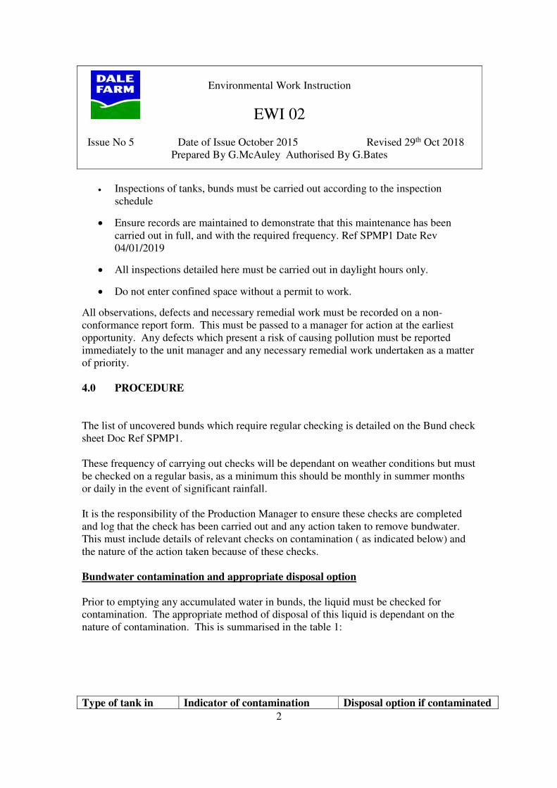
1.0 INTRODUCTION
Bulk tanks are contained within a bunded area or on a spill pallet to provide secondary
containment in the event of a spill or breach from the tank.
The purpose of checking bunds is to:
• Check for bund integrity ie no cracks or holes that could allow liquid to escape
• Establish if the bund contains liquid and may require emptying
A bund may contain liquid because of the leak of the primary containment vessel or from
rain water where the bund is exposed to the elements.
Filling the bund with liquid reduces the volume that can be contained in the event of a
leak and thus, in the event of a major spill or breach of the tank, the bund would overflow
and cause a potential pollution incident.
Therefore, bunds must be regularly checked for accumulated rainwater (Weekly) and
emptied in a controlled manner.
Valves and taps in bunds must NEVER be left open but must always be closed and
locked to prevent vandalism. These should be preferably avoided when purchasing new
bunds
2.0 SCOPE
This procedure covers all bunds
3.0 RESPONSIBILITIES
It is the responsibility of the Yardman / Production Manager or delegate to carry out the
inspections detailed here.
• Failure to carry out such inspections and to maintain this site infrastructure in
adequate condition may result in pollution incidents which could lead to
prosecutions, large fines and clean up costs.
Environmental Work Instruction
EWI 02
Issue No 5 Date of Issue October 2015 Revised 29th Oct 2018
Prepared By G.McAuley Authorised By G.Bates
2
• Inspections of tanks, bunds must be carried out according to the inspection
schedule
• Ensure records are maintained to demonstrate that this maintenance has been
carried out in full, and with the required frequency. Ref SPMP1 Date Rev
04/01/2019
• All inspections detailed here must be carried out in daylight hours only.
• Do not enter confined space without a permit to work.
All observations, defects and necessary remedial work must be recorded on a non-
conformance report form. This must be passed to a manager for action at the earliest
opportunity. Any defects which present a risk of causing pollution must be reported
immediately to the unit manager and any necessary remedial work undertaken as a matter
of priority.
4.0 PROCEDURE
The list of uncovered bunds which require regular checking is detailed on the Bund check
sheet Doc Ref SPMP1.
These frequency of carrying out checks will be dependant on weather conditions but must
be checked on a regular basis, as a minimum this should be monthly in summer months
or daily in the event of significant rainfall.
It is the responsibility of the Production Manager to ensure these checks are completed
and log that the check has been carried out and any action taken to remove bundwater.
This must include details of relevant checks on contamination ( as indicated below) and
the nature of the action taken because of these checks.
Bundwater contamination and appropriate disposal option
Prior to emptying any accumulated water in bunds, the liquid must be checked for
contamination. The appropriate method of disposal of this liquid is dependant on the
nature of contamination. This is summarised in the table 1:
Type of tank in Indicator of contamination Disposal option if contaminated

Environmental Work Instruction
EWI 02
Issue No 5 Date of Issue October 2015 Revised 29th Oct 2018
Prepared By G.McAuley Authorised By G.Bates
3
bund
Fuel / oil Visual check for the presence of
fuel or oil slicks on the surface of
the water
Categorised as hazardous waste
Pump out into sealable container
and dispose of as special waste
For small slicks use an oil
skimmer
Milk / milk products Visual check for discolouration -
milky white water
Presence of odour
(a) If low level of contamination,
bundwater can be disposed of to
EFFLUENT drain RED
(b) If highly contaminated,
transfer to mobile tanker for
disposal
Chemicals Visual check for signs damage,
particularly to valves or pipework
Other indications of
contamination, for instance
particularly large amount of
liquid in bund in relation to
rainfall
Smell of chemicals
Check or confirm contamination
using pH indication strip.
Acceptable levels of pH range
from 5.0 to 10
(a) If low level of contamination,
bundwater can be disposed of to
EFFLUENT drain
RED
(b) If highly contaminated, pump
out into sealable container and
dispose of as HAZARDOUS
waste
If the water is clean with no evidence of contamination as described above this water may
be discharged to drain.
UNDER NO CIRCUMSTANCES MUST ANY WATER NO MATTER HOW
CLEAN IT APPEARS BE DISPOSED OF BY PUMPING INTO A STORM
DRAIN (MARKED BLUE)
In the case of the bund water being contaminated as described above, report this to
management. Management shall investigate the cause of the contamination and take any
necessary corrective and preventative action to prevent a reoccurrence. A non-
conformance report and corrective action sheet must be completed.

Dale Farm – Pennybridge Factory, Site Protection and Monitoring Plan
www.wyg.com creative minds safe hands 27
Appendix B: Previous SPMP (2014)

Integrated Pollution Prevention and Control
(IPPC)
REVIEWED: AUGUST 2014
DALE FARM LTD
PENNYBRIDGE FACTORY: DESIGN OF A SITE
PROTECTION AND MONITORING PROGRAMME THAT DOES
NOT REQUIRE REFERENCE DATA TO BE COLLECTED

Page 2 of 17
SUMMARY
This document represents the part of the design Site Protection and Monitoring Programme
(SPMP) for Dale Farm Ltd - Pennybridge submitted to the Chief Inspector in pursuance of
Condition 4.1.7 of the Permit No P0093/05A (the "Permit") authorising the operation of Dale
Farm Ltd – Pennybridge (the "installation").
This design document is required by Condition 4.6 to be submitted to the Agency within 2
months of the date of issue of the Permit.
An Environmental Monitoring program is presented in section 4 and appendices A – D. This
will not require ground reference samples to be taken, it is proposed that samples will taken
where subsequent ground works are implemented and used as benchmarks for the site closure
plan.
Effluent and surface water sampling will be undertaken as part of the SPMP and the permit
conditions.
Infrastructure monitoring will be undertaken on all aspects of the site that may be a source of
pollution.

Page 3 of 17
Contents
Summary
1.0 Introduction
1.1 Site Location
1.2 Details of the Installation
2.0 Objectives
3.0 Summary of application site report
3.1 Activities to be operated within the installation
3.2 Site Zoning
3.3 Planned Improvements
3.4 Assessment of the need to collect further reference samples
3.5 Updated Conceptual site Model
3.6 Uncertainties and Assumptions in CSM
4.0 Monitoring Program
4.1 Objectives of the Monitoring Program
4.1.1 Objectives of Environmental Monitoring Program
4.1.2 Objectives of the Infrastructure Monitoring Program
4.2 Environmental Monitoring Infrastructure
4.2.1 Location
4.2.2 Surface Water Monitoring
4.2.3 Effluent water monitoring
4.2.4 Soil Monitoring
4.3 Environmental Monitoring Program
4.3.1 Monitoring frequency
4.3.2 Sampling and analysis protocols
4.3.3 Personnel Issues
4.4 Infrastructure Monitoring Program
4.4.1 Personnel Issues
4.5 Assessment and Reporting Procedures
4.5.1 Assessment Procedure

Page 4 of 17
4.5.2 Reporting procedure
4.5.3 Recording and data management
5.0 References
6.0 Glossary
Appendices
Appendix A - Figures and Plans
Appendix B - Investigation and Sampling Protocols
Appendix C - Analytical Protocols and Laboratory Accreditation
Appendix D - Quality Assurance and Quality Control

Page 5 of 17
1.0 Introduction
This Site Protection and Monitoring Program has been designed by Geoffrey Bates
Compliance Manager Dale Farm Ltd. The following documents have been used in the
preparation of the program
The application site report prepared by Enviros Consulting Ltd as part of the permit
application
• Accident plan in section B2.8 of the permit application
• PPC permit No P0093/05A
• Glover site investigations Ltd 09 - 0439
1.1 Site Location
The installation is located at Pennybridge Industrial Estate Larne Rd Ballymena Co Antrim
BT42 3HB. The centre of the site is at National Grid Reference IJ 31164019. The site covers
an area of approximately 5.5 Ha and can be seen in Figure 1 of Appendix A1.
Pennybridge Factory
1.2 Details of Installation
Details of the operations conducted under the permit were provided in the PPC permit
application (Ref. 1) and ASR (Ref. 2). The main activities operated are as follows

Page 6 of 17
• Milk intake/reception;
• Milk pasteurisation and separation;
• Cream production;
• Orange concentrate processing;
• Packaging lines;
• Chilled storage;
• Plant washing activities;
• Boiler house;
• Packaging and distribution; and
• Engineering/maintenance areas.
In addition, there are a number of small operations that are being undertaken within the area
of the installation, which are outside of the scope of the PPC permit. These mainly relate to
vehicle haulage activities undertaken by contractors and NAMPAK blow moulding facility.
2.0 Objectives
The objectives of this report are:
To design a monitoring programme for the installation to:
Monitor the effectiveness of pollution prevention infrastructure and management procedures
to provide an early warning of any loss of containment.
To review and if necessary amend the inspection, testing and maintenance programme for
pollution prevention infrastructure at the installation to ensure their continued integrity
To collect data on the natural ground conditions at the installation to verify the conceptual
site model and to assist in the permit surrender process
3.0 Summary of the application site report
The main findings of the Application report are summarised in this chapter
3.1 Activities to be operated within the installation
Site operations were reviewed by Enviros Consulting to identify activities operated within the
PPC installation that could lead to future ground contamination
The assessment indicated that there was a reasonable possibility of future land pollution
occurring for the following activities under current conditions
1. Storage of milk
2. Delivery of diesel
3. Storage of waste oil and

Page 7 of 17
4. Potential leakage from effluent drainage systems
3.2 Site Zoning
The site has been divided into four zones based on the site setting and the location of
potentially polluting substances. These zones are shown on figure 2 of appendix A and are
listed below
1. Raw milk storage area
2. Diesel storage
3. Waste oil storage area and
4. Effluent drains
3.3 Planned improvements
Improvements since 2006
1. Construction of the NAMPAK facility
2. Conversion of boilers to natural Gas
3. Construction of new central distribution store including new drainage and new oil
interceptor
4. Construction of new lorry park, including new oil interceptor
5. Upgrade of cream effluent drainage system
6. Upgrade of effluent drains at intake
Table 1 Assessment of the need to collect reference data
Potential future
source identified
Relevant
substance
Planned improvements Soil and ground
water reference
data required?
Bulk milks intake
storage and despatch
Biological
Oxygen Demand
Formal documented visual
inspections
N
Diesel delivery and
storage
Hydrocarbons Inspection and reporting of
tank and bund condition.
Improvements
implemented when
necessary. Trained staff to
oversee all deliveries
N
Effluent Biological
Oxygen Demand
5 year rolling program
inspections
N

Page 8 of 17
3.5 Updated Conceptual site Model
Key elements of the conceptual site model are summarised in table 2.
Aspect Details
Geology Drift – Alluvium (laminated silt, fine sand and
gravel)
Solid – Lower Basalt Formation
Hydrogeology Site underlain by a locally important aquifer in
which groundwater flow is dominantly through
fissures and other discontinuities. It has been
classified as moderately permeable.
Surface Water Features The closest watercourse is an unnamed
tributary of the Deerfin Burn and runs along
the north-western side of the installation
boundary. The Deerfin Burn has a ‘Fair’
Biological classification and a ‘Fairly Good’
chemical classification.
Ecological Receptors No ecologically sensitive areas within 500m of
the site.
Summary of Receptors (Pathways) Land (spills and leaks to ground);
Locally important aquifer (leaching from soils,
and percolation through permeable ground);
Unnamed tributary of the Deerfin Burn and the
undesignated stream/drain to the North-west of
the site (site drainage and groundwater flow).
Activities Identified with
Reasonable Possibility of Future
Pollution Occurring
Storage of milk;
Delivery of diesel;
Storage of waste oil;
Potential leakage from effluent drainage
systems.
Potential spillage into storm drains
Land Pollution History & Main
Pollution Incidents
Agricultural use:
Industrial estate construction; and
Redundant oil storage area.
Contamination Identified in
Previous Investigations
Ground analysis was carried out in 2009
during the construction of the blow moulding
facility and in 2010 for the construction of the
distribution depot, no contamination identified
3.6 Uncertainties and Assumptions in CSM
The following uncertainties and assumptions are implicit in the CSM described:
• Thickness and composition of Made Ground and Boulder Clay across the site is not
known in the absence of intrusive investigation data;
• The depth to groundwater is not known;
• Site personnel report that there have been no known pollution incidents but it is
possible that other incidents have occurred since the current factory existed; and

Page 9 of 17
• Pollution incidents may have occurred from before the current factory existed
4.0 Monitoring Programme
4.1 Objectives of the Monitoring Programme
The objectives of the monitoring program are to demonstrate that the pollution prevention
measures will be inspected and maintained over the lifetime of the permit in such a way that
future pollution to land is not caused by installation activities
4.1.1 Objectives of Environmental Monitoring Programme
The requirement for an ongoing monitoring program will be assessed using the results of the
updated CSM in relation to any site works or site ground investigation. The monitoring
program will determine the effectiveness of the pollution control infrastructure and
containment measures and will assist in determining potential emissions.. The program will
allow for the determination and indication of potential pollutants within the site and provide
details on long term changes in ground conditions
4.1.2 Objectives of Infrastructure Monitoring Programme
To test the integrity of the pollution infrastructure currently in place and evaluate the
monitoring, inspection and testing program in place.
4.2 Environmental Monitoring Infrastructure
4.2.1 Location
Figure 1 of Appendix A1 shows the proposed location of monitoring points at the installation.
Table 3
Sampling Location summary
Emission point reference Source Receiving water
W1 Storm water run off Unnamed tributary of the
Deerfin burn
W2 Storm water run off Unnamed tributary of the
Deerfin burn
4.2.2 Surface Water monitoring
The proposed completion details of each groundwater monitoring installation are as detailed
in the permit as follows
Table 4
Emission limits

Page 10 of 17
Release point Parameter Value requirement
W1 & W2 Suspended
solids
50mg/l Quarterly spot
BOD 50mg/l Quarterly spot
pH 6 – 9 Quarterly spot
VOG None Weekly spot
Temperature 25Deg C Weekly spot
.4.2.3 Effluent Water Monitoring
Trade effluent is discharged off site to NI water
Table 5
Emission limits
Release point Parameter Value Monitoring
Requirement
S1 COD 4000mg/l Monthly spot
sample Suspended
solids
800mg/l
pH 5 - 10
Temperature <45 Deg C
Max daily
volume
550m3
4.2.4 Soil Monitoring
Soil samples will be taken from site works on the zoned areas as and when site works are
undertaken eg for infrastructure improvements
Should soil monitoring be required other than after a spillage or pollution incident then
samples will be analysed typically for the following
• Total petroleum hydrocarbons
• Heavy fuel oil, diesel range organics
• PAH, PTE’s and nitrogen compounds
• TN, NO3, NH4 and pH
These will form the base data for the site. The sampling protocol is detailed in appendix B
and analytical Techniques in Appendix C
4.3 Environmental Monitoring Programme

Page 11 of 17
4.3.1 Monitoring Frequency
The proposed environmental monitoring programme
Table 4
Monitoring Frequency
Surface water Quarterly/weekly
Emissions from effluent
drainage system
Monthly
Soil samples from zoned
areas
During ground works
4.3.2 Sampling and Analysis Protocols
The protocols for analysis are summarised below and reproduced in Appendix C.
Sampling protocols are contained within Appendix B.
4.3.3 Personnel Issues
Personnel responsible for sampling, maintenance and inspection will be trained in
environmental monitoring to an appropriate level to ensure compliance with the quality
assurance and quality control plan.
4.4 Infrastructure Monitoring Programme
As detailed within section B2.3 of the main application there are documented procedures to
control process operations. The following table will summarise the inspection procedures
Table 5
Activity Inspection details
Diesel fuel delivery Checks are made at each delivery, all suppliers are trained
in procedures and visual checks are made before, during
and after transfer of diesel. Tank bunds will be inspected
every month
Diesel fuel storage Tank bunds will be checked each month, level gauges are
fitted
Delivery of bulk milk
products
Bulk products will only be transferred when personnel are
present and a spill kit available. The tanker will be
inspected prior to filling or despatch.
Despatch of bulk milk
products
Bulk products will only be transferred when personnel are
present and a spill kit available. The tanker will be
inspected prior to filling or despatch.
Trade effluent drains A visual inspection of the drainage system will be carried

Page 12 of 17
out quarterly. Any drains, which is reported to be damaged,
or not free flowing will be cleaned and further inspection
completed if necessary.
Storm drains A visual inspection of the drainage system will be carried
out quarterly. Any drains, which are reported to be
damaged, or not free flowing will be cleaned and further
inspection completed if necessary.
Internal flooring A visual inspection of the internal flooring will be carried
out monthly. Any flooring which is reported to be in a poor
condition will be repaired
hardstanding A visual inspection of the external yard will be carried out
monthly. Any flooring which is reported to be in a poor
condition will be repaired
Chemical bunds Various areas around the site as identified in the ASR,
these will be checked monthly
Milk storage Milk is stored in 10 external tanks, 5 raw milk and
5processed milk. The tanks are visually inspected prior to
filling, all tanks have high level alarms and are checked
annually
Waste oil storage The waste oil storage is located in the oil store and is on
hard standing, the tank is manually filled and inspected on
a monthly basis
4.4.1 Personnel Issues
Personnel responsible for the inspection, testing and maintenance of pollution prevention
infrastructure are to be trained to an appropriate level to ensure compliance with the
Infrastructure Monitoring Programme. Roles and responsibilities for undertaking the
Programme (including reporting) and ensuring adequate competence of staff are shown in
Appendix E2.
4.5 Assessment and Reporting Procedures
4.5.1 Assessment Procedure
Checklists for the inspection and recording of fixed bunds, hard surfacing in relevant areas
and maintenance will be kept on site. The inspections will be primarily visual to identify any
signs of corrosion, cracks or other damage. Should any damage be identified that could affect
the integrity of the bunds this will be checked through water testing. Damaged hard standing
will be sealed and repaired.
The effluent drainage system will be visually checked every 3 mts to ensure manholes are
clear and free flowing. The system will be maintained in good working order. Manual
inspection of the storm drains will be made every month. Any suspected leaks would be
investigated and remedial action taken as necessary. The site drainage plan will be
maintained and any changes made to the drainage system incorporated.
Ref Environmental Work Instruction EWI No1 ref 3

Page 13 of 17
4.5.2 Reporting Procedure
Summaries of the monitoring data will be sent to the EHS on the 31st of January each year
along with the results of the data assessment, and any recommendations for amendments to
the Monitoring Programme.
4.5.3 Recording and Data Management
Inspection and assessment records of all of the above will be maintained and stored on site.
Records of the infrastructure monitoring will be retained at the installation for a minimum
period of 3 years. The SPMP will be maintained with regular reviews completed at least
every 2yrs. The results of the review and any proposed changes will be discussed with the
regulator.
5.0 References
.
• Dale farm ltd – Pennybridge PPC Permit Application September 2005
• Enviros Consulting Limited, Dale Farm Ltd - Pennybridge PPC ASR 19/9/05
• Environmental Work instruction 01
6.0 Glossary
PPC – Pollution Prevention Control
CSM – Conceptual Site Model
BAT – Best Available Techniques
ASR – Application Site Reports

Page 14 of 17
APPENDIX A
FIGURES AND PLANS
Contents
Figure 1 Site Layout and sampling points
Figure 2 Site zoning

Page 15 of 17
APPENDIX B
SAMPLING PROTOCOLS
Contents
B1 Soil
Any soil samples will be collected under the supervision of a qualified experienced site
investigation engineer.
All samples will be collected as either disturbed samples from an excavator bucket, or from a
window sample tube. The samples will be logged and stored as appropriate prior to being sent
for analysis at an accredited lab.
Each sample will be collected using a clean disposable container and tested for conductivity
prior to being sent for analysis.
B2 Groundwater
Ground water if appropriate may be lifted at the window sampling points and analysed as per
standards current at the time in an accredited lab.
Each sample will be collected using a clean disposable container and tested for conductivity
prior to being sent for analysis. The sample will be logged and the conductivity recorded.
B Surface Water
Surface water will be collected from the points identified in figure 2
Each sample will be collected using a clean disposable container and tested for conductivity
prior to being sent for analysis. The sample will be logged and the conductivity recorded.
B5 Infrastructure
Infrastructure monitoring comprises a program of visual inspections.

Page 16 of 17
APPENDIX C
ANALYTICAL PROTOCOLS AND LABORATORY ACCREDITATION
Contents
In house laboratory facilities will be used where applicable
An accredited laboratory (UKAS) will be used for soil, waste and water

Page 17 of 17
APPENDIX D
QUALITY ASSURANCE AND QUALITY CONTROL
Contents
Where possible the analysis will be conducted in laboratories with the appropriate level of
approved accreditation. Detection limits, analysis protocols and accreditation status will be
provided with all reported data.

Dale Farm – Pennybridge Factory, Site Protection and Monitoring Plan
www.wyg.com creative minds safe hands 28
Appendix C: Site Investigation Reports


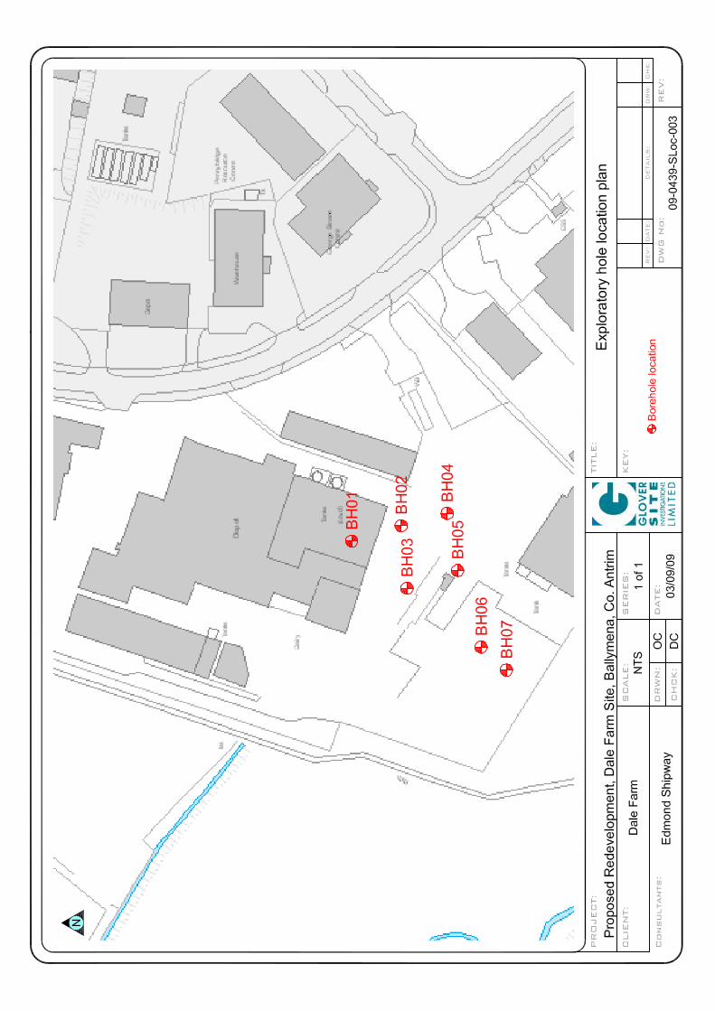

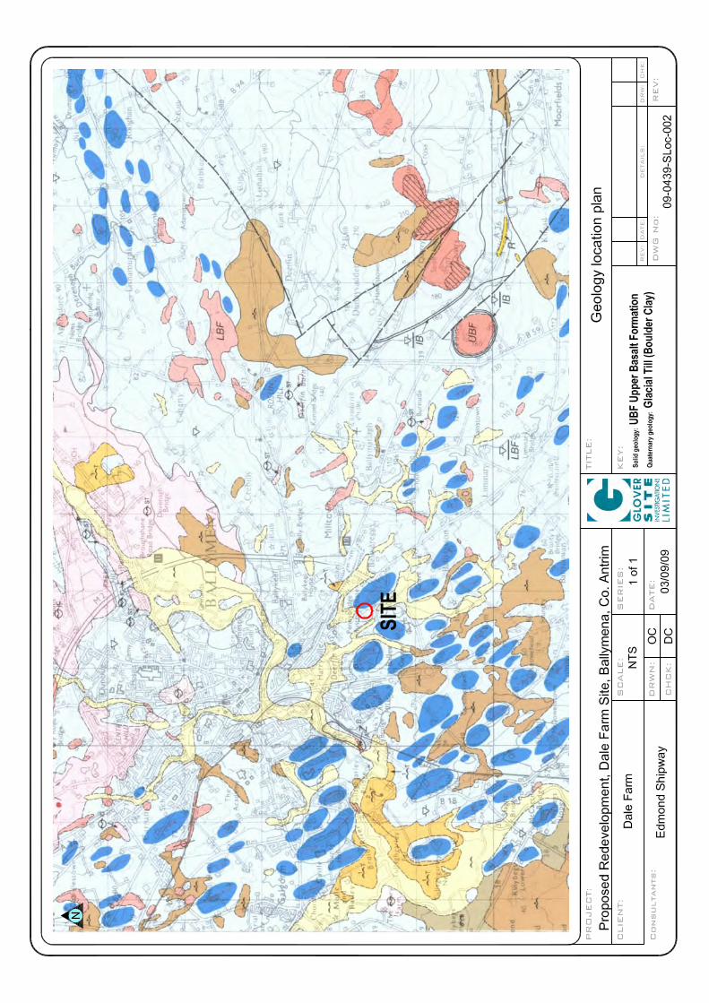


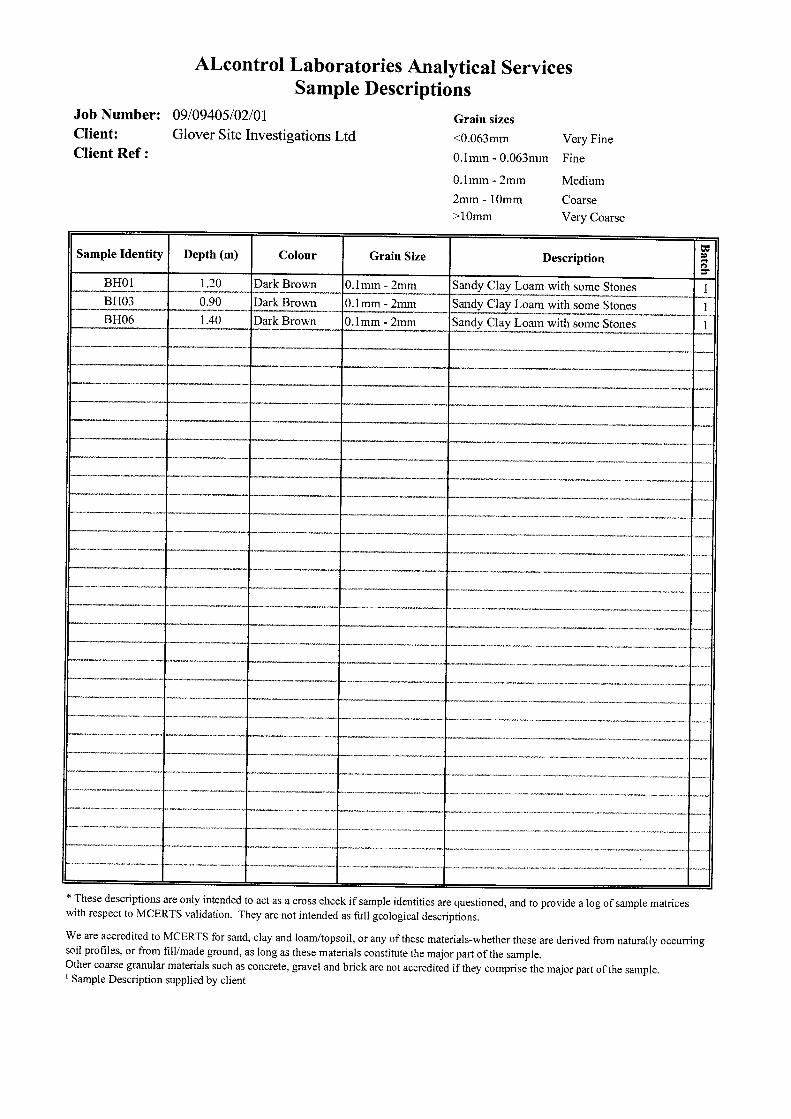
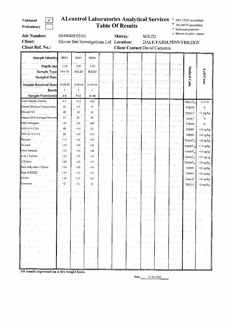


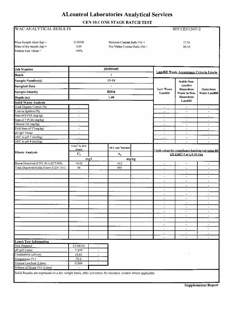


FINAL FOR ISSUE
Dale Farm Pennybridge Industrial Estate Site Investigation
Primary Author: John Cameron Client: Dale Farm Client‟s Representative: Albert Fry Associates Completed: October 2014 Report No.: 14-742 File Location: 14-742 report

Dale Farm, Pennybridge Industrial Estate
Report No.: 14-742
October 2014 Page 1
CONTENTS Document Control Sheet Note on: Methods of describing soils and rocks & abbreviations used on exploratory hole logs
1 AUTHORITY ............................................................................................................ 4
2 SCOPE .................................................................................................................. 4
3 DESCRIPTION OF SITE ............................................................................................. 4
4 SITE OPERATIONS ................................................................................................... 4 4.1 Boreholes ........................................................................................................ 5
5 LABORATORY WORK................................................................................................ 5
6 GROUND CONDITIONS ............................................................................................. 6 6.1 Groundwater .................................................................................................... 6
7 DISCUSSION ........................................................................................................... 6 7.1 Proposed construction ........................................................................................ 6
7.2 Recommendations for construction ......................................................................... 6
7.2.1 Foundations and ground floor construction ........................................................ 6
7.2.2 Soil aggressivity ........................................................................................ 7
7.2.3 Waste disposal ......................................................................................... 7
Soil quality ....................................................................................................... 7
8 REFERENCES ......................................................................................................... 8
APPENDICES Appendix A Site and exploratory hole location plans
Appendix B Borehole and dynamic probe logs
Appendix C Laboratory test results
Appendix D SPT hammer energy measurement report
Dale Farm, Pennybridge Industrial Estate
Report No.: 14-742
October 2014 Page 2
Document Control Sheet Report No.:
14-742
Project title:
Dale Farm, Pennybridge Industrial Estate
Client:
Dale Farm
Client‟s Representative:
Albert Fry Associates
Revision
Status
Report prepared by:
Report reviewed by:
Issue date
0
Final
John Cameron BSc CEng MIEI
Paul Dunlop BEng PhD CEng MIEI
8th October 2014
The works were conducted in accordance with:
Site Investigation in Construction Part 3: Specification for Ground Investigation, Site Investigation Steering Group, published by Thomas Telford Ltd (1993) British Standards Institute (2010) BS 5930:1999 + A2: 2010, Code of practice for site investigations. Incorporating Amendment Nos. 1 and 2, as partially replaced by:
BS EN 1997-2:2007: Eurocode 7. Geotechnical design. Ground investigation and testing
BS EN ISO 22475-1:2006: Geotechnical investigation and testing. Sampling methods and groundwater measurements. Technical principles for execution
BS EN ISO 14688-1:2002: Geotechnical investigation and testing. Identification and classification of soil. Identification and description
BS EN ISO 14688-2:2004: Geotechnical investigation and testing. Identification and classification of soil. Principles for a classification
BS EN ISO 14689-1:2003: Geotechnical investigation and testing. Identification and classification of rock. Identification and description
BS EN ISO 22476-2:2005: Geotechnical investigation and testing. Field testing. Dynamic probing
BS EN ISO 22476-3:2005: Geotechnical investigation and testing. Field testing. Standard penetration test
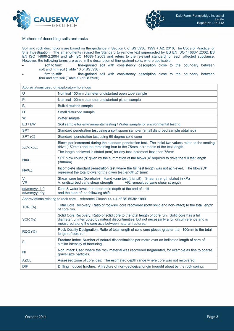
Dale Farm, Pennybridge Industrial Estate
Report No.: 14-742
October 2014 Page 3
Methods of describing soils and rocks Soil and rock descriptions are based on the guidance in Section 6 of BS 5930: 1999 + A2: 2010, The Code of Practice for Site Investigation. The amendments revised the Standard to remove text superseded by BS EN ISO 14688-1:2002, BS EN ISO 14688-2:2004 and EN ISO 14689-1:2003 and refers to the relevant standard for each affected subclause. However, the following terms are used in the description of fine-grained soils, where applicable: soft to firm: fine-grained soil with consistency description close to the boundary between
soft and firm soil (Table 13 of BS5930). firm to stiff: fine-grained soil with consistency description close to the boundary between
firm and stiff soil (Table 13 of BS5930).
Abbreviations used on exploratory hole logs
U Nominal 100mm diameter undisturbed open tube sample
P Nominal 100mm diameter undisturbed piston sample
B Bulk disturbed sample
D Small disturbed sample
W Water sample
ES / EW Soil sample for environmental testing / Water sample for environmental testing
SPT Standard penetration test using a split spoon sampler (small disturbed sample obtained)
SPT (C) Standard penetration test using 60 degree solid cone
x,x/x,x,x,x Blows per increment during the standard penetration test. The initial two values relate to the seating drive (150mm) and the remaining four to the 75mm increments of the test length. The length achieved is stated (mm) for any test increment less than 75mm
N=X SPT blow count „N‟ given by the summation of the blows „X‟ required to drive the full test length (300mm)
N=X/Z Incomplete standard penetration test where the full test length was not achieved. The blows „X‟ represent the total blows for the given test length „Z‟ (mm)
V VR
Shear vane test (borehole) Hand vane test (trial pit) Shear strength stated in kPa V: undisturbed vane shear strength VR: remoulded vane shear strength
dd/mm/yy: 1.0 dd/mm/yy: dry
Date & water level at the borehole depth at the end of shift and the start of the following shift
Abbreviations relating to rock core – reference Clause 44.4.4 of BS 5930: 1999
TCR (%) Total Core Recovery: Ratio of rock/soil core recovered (both solid and non-intact) to the total length of core run.
SCR (%) Solid Core Recovery: Ratio of solid core to the total length of core run. Solid core has a full diameter, uninterrupted by natural discontinuities, but not necessarily a full circumference and is measured along the core axis between natural fractures.
RQD (%) Rock Quality Designation: Ratio of total length of solid core pieces greater than 100mm to the total length of core run.
FI Fracture Index: Number of natural discontinuities per metre over an indicated length of core of similar intensity of fracturing.
NI Non Intact: Used where the rock material was recovered fragmented, for example as fine to coarse gravel size particles.
AZCL Assessed zone of core loss: The estimated depth range where core was not recovered.
DIF Drilling induced fracture: A fracture of non-geological origin brought about by the rock coring.

Dale Farm, Pennybridge Industrial Estate
Report No.: 14-742
October 2014 Page 4
Dale Farm, Pennybridge Industrial Estate
1 AUTHORITY On the instructions of Consulting Engineers, Albert Fry Associates (“the Client‟s Representative”), on behalf of Dale Farm (“the Client”), a ground investigation was undertaken at the above location to provide geotechnical and environmental information the site. This report details the work carried out both on site and in the geotechnical and chemical testing laboratories; it contains a description of the site and the works undertaken, the exploratory hole logs and the laboratory test results. A discussion on the recommendation for construction is also provided. All information given in this report is based upon the ground conditions encountered during the site investigation works, and on the results of the laboratory and field tests performed. However, there may be conditions at the site that have not been taken into account, such as unpredictable soil strata, contaminant concentrations, and water conditions between or below exploratory holes. It should be noted that groundwater levels usually vary due to seasonal and/or other effects and may at times differ to those measured during the investigation. This report was prepared by Causeway Geotech Ltd for the use of the Client and the Client‟s Representative in response to particular instructions. Any other parties using the information contained in this report do so at their own risk and any duty of care to those parties is excluded.
2 SCOPE The extent of the investigation, as instructed by the Client‟s Representative, included boreholes, soil sampling, in-situ and laboratory testing, and the preparation of a report on the findings including recommendations for construction.
3 DESCRIPTION OF SITE As shown on the site location plan in Appendix A, the works were conducted on the site at Dale Farm‟s existing plant at Pennybridge Industrial Estate in Ballymena.
4 SITE OPERATIONS The Site Operations, conducted on 8th September 2014, comprised: four percussion boreholes;
The exploratory holes and insitu tests were located as instructed by the Client‟s Representative, as shown on the exploratory hole location plan in Appendix A.

Dale Farm, Pennybridge Industrial Estate
Report No.: 14-742
October 2014 Page 5
4.1 Boreholes Four boreholes (BH01 – BH04) were put down in 150mm diameter using Dando Terrier percussion boring rig. BH01, BH03 and BH04 were down through Made Ground varying between 0.6m and 2.5m in thickness. All four boreholes terminated in very stiff glacial till. Disturbed (small and bulk bag) samples and environmental samples were taken within the encountered strata. Standard penetration tests were carried out at 1m depth intervals using the split spoon sampler (SPT). The penetrations are stated for those tests for which the full 150mm seating drive or 300mm test drive was not possible. The N-values provided on the borehole logs are uncorrected and no allowance has been made for energy ratio corrections. Any water strikes encountered during boring were recorded along with any changes in their levels as the borehole proceeded. Appendix B presents the borehole logs. The SPT hammer energy measurement report is provided in Appendix D. Details of the SPT hammer used is provided on the individual borehole logs.
5 LABORATORY WORK Upon their receipt in the laboratory, all disturbed samples were carefully examined and accurately described and their descriptions incorporated into the borehole logs. Laboratory testing of soils comprised: Moisture content Atterberg Limit Particle size distribution analysis. pH and water soluble sulphate content. In addition, environmental screening and WAC testing was conducted on selected environmental samples by Chemtest at its laboratory in Newmarket, Suffolk. The test results are presented in Appendix C.

Dale Farm, Pennybridge Industrial Estate
Report No.: 14-742
October 2014 Page 6
6 GROUND CONDITIONS The exploratory holes encountered the following ground types: Made Ground: identified in boreholes BH01, BH03 & BH04 to depths ranging from 0.60m to
2.50m, generally comprised of reworked Glacial Till (boulder Clay) Glacial Till: as soft to firm becoming very stiff sandy gravelly clay or silt with low cobble and
boulder content to 3.3m in BH03.
6.1 Groundwater Groundwater was not encountered, during exploration.
7 DISCUSSION
7.1 Proposed construction No construction details were available to Causeway Geotech Ltd when preparing this Report.
7.2 Recommendations for construction
7.2.1 Foundations and ground floor construction Foundations should transfer loading to below Made Ground. The recommended foundation construction and allowable bearing pressure (ABP) at the four borehole locations are as follows: Table 1: Construction recommendations
Borehole
Depth Below
EGL* to Suitable Bearing Stratum
Estimated ABP (kPa)
Strata description
Foundation type
Ground floor construction Groundwater
BH01 1.80 200 Very stiff glacial till
Strip and Pad or trench
fill Suspended
Not present during
exploration
BH02 1.40 200 Very stiff glacial till
Strip and Pad or trench fill
Suspended Not present
during exploration
BH03 2.40 200 Very stiff glacial till
Strip and Pad or trench fill
Suspended Not present
during exploration
BH04 2.50 200 Very stiff glacial till
Strip and Pad or trench fill
Suspended Not present
during exploration
* Existing Ground Level

Dale Farm, Pennybridge Industrial Estate
Report No.: 14-742
October 2014 Page 7
The depth of Made Ground across the site indicates the use of strip and pad or deep trench foundations are recommended along with suspended floors.
7.2.2 Soil aggressivity An assessment of the Aggressive Chemical Environment for Concrete (ACEC) was undertaken through reference to the Building Research Establishment (BRE) Special Digest 1 (2005). As noted by BRE Special Digest 1, sulphates in the soil and groundwater are the chemical agents most likely to attack concrete. The extent to which sulphates affect concrete is linked to their concentrations, the type of ground, the presence of groundwater, the type of concrete and the form of construction in which concrete is used. BRE Special Digest 1 identifies four different categories of site which require specific procedures for investigation for aggressive ground conditions:
Sites not subjected to previous development and not perceived as containing pyrite; Sites not subjected to previous development and perceived as containing pyrite; Brownfield sites not perceived as containing pyrite; Brownfield sites perceived as containing pyrite.
For the purposes of this report the site was classified as having been subject to previous development and not perceived as containing pyrite. The results of chemical tests (pH and water soluble sulphate contents) on soil samples indicate Design Sulphate Class DS-1 and ACEC Class AC-1 – reference Table C2 of BRE Special Digest 1 (Building Research Establishment, 2005). The Special Digest does not require any measures to protect underground concrete elements greater that 140mm thick.
7.2.3 Waste disposal
Four samples were sent for Environmental Screening and Two samples were analysed for WAC analysis, the results of which are presented in Appendix E. Considering the results for the two samples analysed the soils on site may be disposed of as non-hazardous waste subject to the receiving landfill permitting the material on receipt of the laboratory results.
Soil quality Selected soil samples were analysed for a range of potential contaminants including: Metals; Speciated total petroleum hydrocarbons (TPH); Speciated polycyclic aromatic hydrocarbons (PAH); and Cyanide.
Dale Farm, Pennybridge Industrial Estate
Report No.: 14-742
October 2014 Page 8
In the initial examination of the potential risk of site contamination, the laboratory results have been compared to the following available assessment criteria relevant to the proposed land use: the Environment Agency Soil Guideline Values (SGVs) published, in 2009. These relate to
arsenic, nickel, mercury, selenium, cadmium, benzene, toluene, ethylbenzene, xylenes, and phenol.
The results from the selected samples do not identify significantly elevated concentrations for the compounds analysed considering a commercial redevelopment. It should be noted that the above assessment is based on the results of the selected soil samples and available SGVs. Any potential contamination identified during site development by visual or olfactory means should be further investigated, including additional laboratory testing, and appropriate health & safety, waste disposal and remediation measures adopted. Where site levels are to be reduced as part of development work the soil chemistry results indicate the material is likely to be considered non-hazardous waste n. It is recommended that the results of this report are presented to the landfill operator prior to disposal to ensure they are informed of the potential waste classification enabling them to remain in compliance with their relevant permits.
8 REFERENCES BS 1377: 1990: Methods of test for soils for civil engineering purposes. British Standards Institution. BS 5930+A2: 2010: Code of practice for site investigations (Amendment 2). British Standards Institution. BS EN 1997-2: 2007: Eurocode 7 - Geotechnical design - Part 2 Ground investigation and testing. British Standards Institution. BS EN ISO 14688-1: 2002: Geotechnical investigation and testing - Identification and classification of soil - Part 1 Identification and description. British Standards Institution. Building Research Establishment (2005) BRE Special Digest 1, Concrete in aggressive ground.

Appendix A Site and exploratory hole location plans
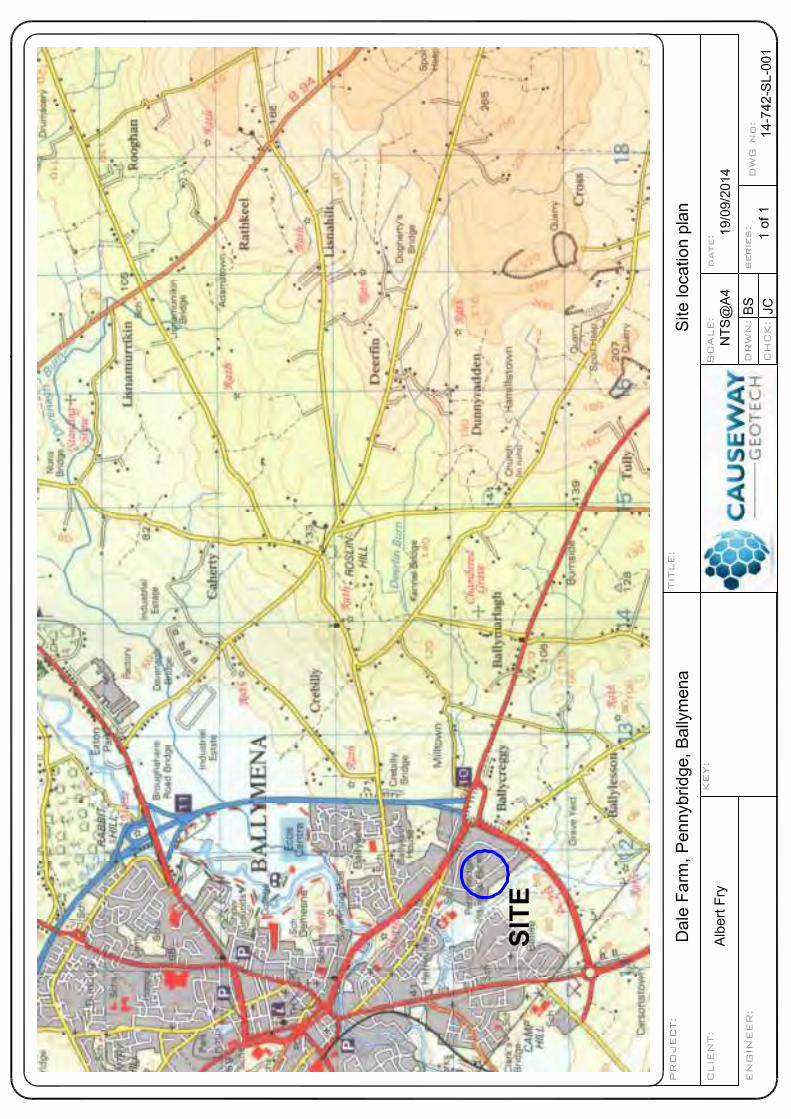
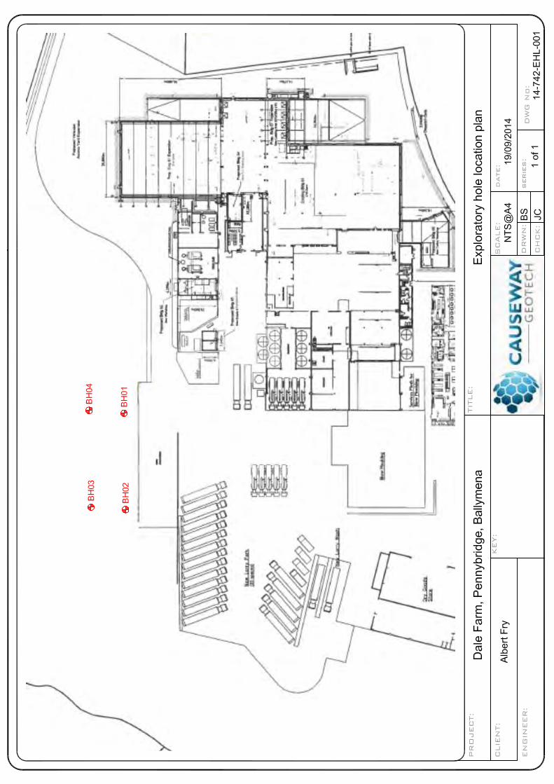

Appendix B Borehole logs
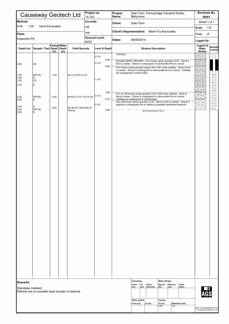
Causeway Geotech LtdProject no.
14-742
ProjectName:
Dale Farm, Pennybridge Industrial Estate, Ballymena
Borehole No.
BH01
Method:
0.00 1.00 Hand Excavated
Plant:
Inspection Pit
Co-ords:
mE
mN
Ground Level:
MOD
Client: Dale Farm
Client's Representative: Albert Fry Associates
Dates: 08/09/2014
Sheet 1 of 1
Scale: 1:50
Crew: JS
Logged By:
Depth (m)
0.50
1.001.001.00
1.45
2.002.00
2.452.502.60
Sample / Test
ES
SPT(S)DES
D
SPT(S)D
DSPT(S)D
CasingDepth
(m)
1.00
2.00
2.50
WaterDepth
(m)Field Records
N=12 (2,2/3,3,3,3)
N=55 (4,11/11,14,14,16)
50 (25 for 75mm/50 for 75mm)
Level & Depth
(0.30)
(0.30)
(1.20)
(0.30)
(0.50)
0.30
0.60
1.80
2.10
2.60
Stratum Description
TOPSOIL
Possible MADE GROUND: Firm brown sandy gravelly CLAY. Sand is fine to coarse. Gravel is subangular to subrounded fine to coarse
Firm brown sandy gravelly clayey SILT with some cobbles. Sand is fine to coarse. Gravel is subangular to subrounded fine to coarse. Cobbles are subangular to subrounded
Firm to stiff brown sandy gravelly CLAY with some cobbles. Sand is fine to coarse. Gravel is subangular to subrounded fine to coarse. Cobbles are subangular to subroundedVery stiff brown sandy gravelly CLAY. Sand is fine to coarse. Gravel is angular to subangular fine to medium (possible weathered bedrock)
End of borehole at 2.60 m
Legend &Water
Strikes
BackfillInstalls
Remarks
Standpipe installedRefusal met on possible large boulder or bedrock
Chiselling:
From(m)
To(m)
Time(hh:mm)
Water Added:
From (m) To (m)
Water Strikes:
Struck(m)
Rose to(m)
Time(min)
Casing:
To (m) Diameter (mm)
2.60 150www.causewaygeotech.com
© Causeway Geotech Ltd

Causeway Geotech LtdProject no.
14-742
ProjectName:
Dale Farm, Pennybridge Industrial Estate, Ballymena
Borehole No.
BH02
Method:
0.001.00
1.002.60
Hand ExcavatedLight Percussion
Plant:
Inspectin Pit+Dando Terrier
Co-ords:
mE
mN
Ground Level:
MOD
Client: Dale Farm
Client's Representative: Albert Fry Associates
Dates: 08/09/2014
Sheet 1 of 1
Scale: 1:50
Crew: JS
Logged By:
Depth (m)
0.50
1.001.001.00 - 2.00
1.45
2.00
2.452.502.60
Sample / Test
ES
SPT(S)ESB
D
SPT(S)
DSPT(S)D
CasingDepth
(m)
1.00
2.00
2.50
WaterDepth
(m)Field Records
N=18 (2,3/3,3,5,7)
N=55 (3,7/11,14,14,16)
50 (25 for 75mm/50 for 75mm)
Level & Depth
(0.20)
(0.70)
(0.50)
(0.80)
(0.40)
0.20
0.90
1.40
2.20
2.60
Stratum Description
TOPSOIL
Soft to firm orange brown sandy gravelly CLAY. Sand is fine to coarse. Gravel is subangular to subrounded fine to medium
Firm to stiff brown sandy gravelly CLAY with occasional cobbles. Sand is fine to coarse. Gravel is angular to subangular fine to coarse. Cobbles are angular to subangular (possible weathered bedrock)
Stiff to very stiff brown sandy gravelly CLAY/ SILT with occasional cobbles. Sand is fine to coarse. Gravel is angular to subangular fine to coarse. Cobbles are angular to subangular (possible weathered bedrock)
Very stiff brown sandy gravelly CLAY with occasional cobbles. Sand is fine to coarse. Gravel is angular to subangular fine to coarse. Cobbles are angular to subangular (possible weathered bedrock)
End of borehole at 2.60 m
Legend &Water
Strikes
BackfillInstalls
Remarks
Refusal met on possible large boulder or bedrock
Chiselling:
From(m)
To(m)
Time(hh:mm)
Water Added:
From (m) To (m)
Water Strikes:
Struck(m)
Rose to(m)
Time(min)
Casing:
To (m) Diameter (mm)
2.60 150www.causewaygeotech.com
© Causeway Geotech Ltd

Causeway Geotech LtdProject no.
14-742
ProjectName:
Dale Farm, Pennybridge Industrial Estate, Ballymena
Borehole No.
BH03
Method:
0.001.00
1.003.30
Hand ExcavatedLight Percussion
Plant:
Inspection Pit+Dando Terrier
Co-ords:
mE
mN
Ground Level:
MOD
Client: Dale Farm
Client's Representative: Albert Fry Associates
Dates: 08/09/2014
Sheet 1 of 1
Scale: 1:50
Crew: JS
Logged By:
Depth (m)
0.50
1.00
1.00
1.00 - 2.00
1.45
1.50
2.00
2.00
2.40 - 3.00
2.45
2.50
3.00
3.30
Sample / Test
ES
SPT(S)ESB
DES
SPT(S)ES
BDES
SPT(S)
D
CasingDepth
(m)
1.00
2.00
3.00
WaterDepth
(m)Field Records
N=12 (1,2/2,4,3,3)
N=17 (2,4/2,3,5,7)
72 (5,14/72 for 150mm)
Level & Depth
(0.20)
(2.20)
(0.90)
0.20
2.40
3.30
Stratum Description
TOPSOIL
MADE GROUND: Firm brown sandy gravelly CLAY with some cobbles. Sand is fine to coarse. Gravel is subrounded to subangular fine to coarse. Cobbles are subrounded to subangular
Stiff to very stiff brown sandy gravelly clayey SILT with some cobbles and boulders. Sand is fine to coarse. Gravel is angular to subangular fine to coarse. Cobbles and boulders are subrounded to subangular (Possible weathered bedrock)
End of borehole at 3.30 m
Legend &Water
Strikes
BackfillInstalls
Remarks
Refusal met on possible bedrock
Chiselling:
From(m)
To(m)
Time(hh:mm)
Water Added:
From (m) To (m)
Water Strikes:
Struck(m)
Rose to(m)
Time(min)
Casing:
To (m) Diameter (mm)
3.30 150www.causewaygeotech.com
© Causeway Geotech Ltd

Causeway Geotech LtdProject no.
14-742
ProjectName:
Dale Farm, Pennybridge Industrial Estate, Ballymena
Borehole No.
BH04
Method:
0.001.00
1.002.60
Hand ExcavatedLight Percussion
Plant:
Inspection Pit+Dando Terrier
Co-ords:
mE
mN
Ground Level:
MOD
Client: Dale Farm
Client's Representative: Albert Fry Associates
Dates: 08/09/2014
Sheet 1 of 1
Scale: 1:50
Crew: JS
Logged By:
Depth (m)
0.50
1.001.001.00 - 2.00
1.451.50
2.002.002.00 - 2.50
2.452.502.502.60
Sample / Test
ES
SPT(S)ESB
DES
SPT(S)ESB
DESSPT(S)D
CasingDepth
(m)
1.00
2.00
2.50
WaterDepth
(m)Field Records
N=16 (2,3/6,3,3,4)
N=25 (2,4/7,5,6,7)
50 (25 for 75mm/50 for 75mm)
Level & Depth
(0.20)
(2.30)
(0.10)
0.20
2.502.60
Stratum Description
TOPSOIL
MADE GROUND: Firm to stiff orange brown sandy gravelly CLAY with some cobbles and boulders. Sand is fine to coarse. Gravel is subangular to subrounded fine to coarse. Cobbles and boulders are subangular to subrounded
Very stiff brown sandy gravelly CLAY with occasional cobbles. Sand is fine to coarse. Gravel is angular to subangular fine to coarse. Cobbles are angular to subangular (possible weathered bedrock)
End of borehole at 2.60 m
Legend &Water
Strikes
BackfillInstalls
Remarks
Refusal met on possible large boulder or bedrock
Chiselling:
From(m)
To(m)
Time(hh:mm)
Water Added:
From (m) To (m)
Water Strikes:
Struck(m)
Rose to(m)
Time(min)
Casing:
To (m) Diameter (mm)
2.60 150www.causewaygeotech.com
© Causeway Geotech Ltd

Appendix C Laboratory Test Results

Sheet 1 of 1
Contract: Dale Farm, Pennybridge Industrial Estate, Ballymena Causeway Geotech Ltd
Job No.: 14-742
Moisture content, Atterberg Limits & Particle Density
Tests 3.2, 4.3, 5.3 & 8.3 of BS 1377 : Part 2 : 1990
EH Moisture Passing Liquid Plastic Plasticity Casagrande Particle
No. Content 425μm Limit Limit Index Classification Density
Type No. at (m) to (m) (%) Sieve (%) (%) (%) (%) (Mg/m3)
SampleSample
Depth
BH01 D 1.00 34 60 50 37 13 MI/MH
BH02 D 1.45 20 51 37 NP NP
BH03 B 1.00 18
BH03 B 2.40 17 35 34 26 8 ML
BH04 B 1.00 29
BH04 D 2.45 19 62 41 25 16 CI
NP non-plastic soil
$ Insufficient material for Limits tests.

Cause
way G
eote
ch L
tdPart
icle
Siz
e D
istr
ibuti
on
BS1377:1
990 P
art
2 C
lause
9.2
and 9
.5
125
100
90
100
75
100
63
100
50
100
37.5
96
28
96
20
94
14
89
10
85
6.3
81
580
3.3
578
274
1.1
871
0.6
66
0.4
25
63
0.3
59
0.2
12
56
0.1
553
0.0
63
48
0.0
345
38.3
0.0
181
26.5
0.0
096
19.2
0.0
054
13.3
0.0
032
5.9
0.0
016
2.9
Sand
26%
Cla
y
3%
Silt
45%
fine
mediu
mcoars
e
Gra
vel 2
6%
Part
icle
siz
e
(mm
)
%
pass
ing
sedim
enta
tion
si
eve s
izes
(mm
)
coars
efi
ne
mediu
mCobble
s
0%
to (
m)
B2
2.0
0
Pro
ject:
Dale
Farm
, Pennybri
dge Indust
rial Est
ate
,
Ballym
ena
Explo
rato
ry
Hole
No.:
BH
04
Job N
o.:
14-7
42
Sam
ple
Type
No.
at
(m)
6.3
5
3.35
2
1.18
0.600
0.425
0.300
0.212
0.150
0.063
0
10
20
30
40
50
60
70
80
90
100 0.001
0.01
0.1
1
% passing
part
icle
siz
e (
mm
)

Cause
way G
eote
ch L
tdPart
icle
Siz
e D
istr
ibuti
on
BS1377:1
990 P
art
2 C
lause
9.2
and 9
.5
125
100
90
100
75
100
63
100
50
100
37.5
100
28
100
20
96
14
92
10
88
6.3
83
581
3.3
579
276
1.1
873
0.6
69
0.4
25
67
0.3
64
0.2
12
60
0.1
557
0.0
63
50
0.0
345
41.4
0.0
180
30.3
0.0
098
15.9
0.0
055
8.0
0.0
032
4.8
0.0
016
3.2
Sand
26%
Cla
y
3%
Silt
47%
fine
mediu
mcoars
e
Gra
vel 2
4%
Part
icle
siz
e
(mm
)
%
pass
ing
sedim
enta
tion
si
eve s
izes
(mm
)
coars
efi
ne
mediu
mCobble
s
0%
to (
m)
B1
1.0
0
Pro
ject:
Dale
Farm
, Pennybri
dge Indust
rial Est
ate
,
Ballym
ena
Explo
rato
ry
Hole
No.:
BH
04
Job N
o.:
14-7
42
Sam
ple
Type
No.
at
(m)
6.3
5
3.35
2
1.18
0.600
0.425
0.300
0.212
0.150
0.063
0
10
20
30
40
50
60
70
80
90
100 0.001
0.01
0.1
1
% passing
part
icle
siz
e (
mm
)

Cause
way G
eote
ch L
tdPart
icle
Siz
e D
istr
ibuti
on
BS1377:1
990 P
art
2 C
lause
9.2
and 9
.5
125
100
90
100
75
100
63
100
50
94
37.5
91
28
87
20
82
14
79
10
72
6.3
65
562
3.3
557
250
1.1
844
0.6
38
0.4
25
35
0.3
32
0.2
12
29
0.1
526
0.0
63
19
0.0
347
14.0
0.0
184
8.4
0.0
098
5.6
0.0
055
3.9
0.0
032
1.7
0.0
016
0.6
Sand
31%
Cla
y
1%
Silt
18%
fine
mediu
mcoars
e
Gra
vel 5
0%
Part
icle
siz
e
(mm
)
%
pass
ing
sedim
enta
tion
si
eve s
izes
(mm
)
coars
efi
ne
mediu
mCobble
s
0%
to (
m)
B2
2.4
0
Pro
ject:
Dale
Farm
, Pennybri
dge Indust
rial Est
ate
,
Ballym
ena
Explo
rato
ry
Hole
No.:
BH
03
Job N
o.:
14-7
42
Sam
ple
Type
No.
at
(m)
6.3
5
3.35
2
1.18
0.600
0.425
0.300
0.212
0.150
0.063
0
10
20
30
40
50
60
70
80
90
100 0.001
0.01
0.1
1
% passing
part
icle
siz
e (
mm
)

Cause
way G
eote
ch L
tdPart
icle
Siz
e D
istr
ibuti
on
BS1377:1
990 P
art
2 C
lause
9.2
and 9
.5
125
100
90
100
75
89
63
74
50
70
37.5
67
28
62
20
53
14
48
10
42
6.3
37
536
3.3
533
229
1.1
826
0.6
23
0.4
25
21
0.3
20
0.2
12
18
0.1
517
0.0
63
15
SE
D
Sand
15%
Fin
es
15%
fine
mediu
mcoars
e
Gra
vel 4
4%
Part
icle
siz
e
(mm
)
%
pass
ing
sedim
enta
tion
si
eve s
izes
(mm
)
coars
efi
ne
mediu
mCobble
s
26%
to (
m)
B1
1.0
0
Pro
ject:
Dale
Farm
, Pennybri
dge Indust
rial Est
ate
,
Ballym
ena
Explo
rato
ry
Hole
No.:
BH
03
Job N
o.:
14-7
42
Sam
ple
Type
No.
at
(m)
6.3
5
3.35
2
1.18
0.600
0.425
0.300
0.212
0.150
0.063
0
10
20
30
40
50
60
70
80
90
100 0.001
0.01
0.1
1
% passing
part
icle
siz
e (
mm
)

Cause
way G
eote
ch L
tdPart
icle
Siz
e D
istr
ibuti
on
BS1377:1
990 P
art
2 C
lause
9.2
and 9
.5
125
100
90
100
75
100
63
100
50
100
37.5
100
28
90
20
85
14
80
10
77
6.3
74
573
3.3
570
260
1.1
848
0.6
38
0.4
25
34
0.3
30
0.2
12
27
0.1
525
0.0
63
20
0.0
345
16.2
0.0
181
11.2
0.0
096
8.1
0.0
054
5.6
0.0
032
2.5
0.0
016
1.2
Sand
40%
Cla
y
3%
Silt
17%
fine
mediu
mcoars
e
Gra
vel 4
0%
Part
icle
siz
e
(mm
)
%
pass
ing
sedim
enta
tion
si
eve s
izes
(mm
)
coars
efi
ne
mediu
mCobble
s
0%
to (
m)
B1
1.0
0
Pro
ject:
Dale
Farm
, Pennybri
dge Indust
rial Est
ate
,
Ballym
ena
Explo
rato
ry
Hole
No.:
BH
02
Job N
o.:
14-7
42
Sam
ple
Type
No.
at
(m)
907563
50
37.5
28
20
14
10
6.3
5
3.35
2
1.18
0.600
0.425
0.300
0.212
0.150
0.0630
10
20
30
40
50
60
70
80
90
100 0.001
0.01
0.1
110
100
% passing
part
icle
siz
e (
mm
)

Sheet 1 of 1
Contract: Causeway Geotech Ltd
Job No.: 14-742
CHEMICAL TESTS
Tests 3, 4, 5 & 9 of BS 1377 : Part 3 : 1990
Passing Organic Mass pH
2mm Matter Loss on Soil/water Value
at to Sieve Content Ignition extract @
(m) (m) (%) * (%) # (%) $ (mg/l)
Dale Farm, Pennybridge Industrial Estate, Ballymena
EH
No.
Sulfate Content SO4
Groundwater
(mg/l)
Sample
Depth Sample
Type No.
BH01 D 1.45 108 7.5
BH02 B 1.00 78 7.0
BH03 B 1.00 72 7.5
BH04 B 1.00 95 7.5
* Walkley and Black's dichromate method–Clause 3
# Average of 3 specimens-Clause 4
$ Water soluble SO4 from 2:1 water-soil extract-Clause 5.5
@ Average of 2/3 specimens-Clause 9.5
Clause Nos. of BS1377:Part 3:1990
Unit 7-8 Hawarden Business Park
Manor Road (off Manor Lane)
Hawarden
Deeside
CH5 3US
Tel: (01244) 528700
Fax: (01244) 528701
email: [email protected]
Website: www.alcontrol.com
Causeway Geotech Ltd
8 Drumahiskey Road
Ballymoney
Co. Antrim
BT53 7QL
Attention: Stephen Franey
CERTIFICATE OF ANALYSIS
Location:
Your Reference:
Sample Delivery Group (SDG):
Customer:
Date: 03 October 2014
D_CAUSWY_BAL
140911-76
Dale Farm, Ballymena
We received 14 samples on Wednesday September 10, 2014 and 4 of these samples were scheduled for analysis which
was completed on Friday October 03, 2014. Accredited laboratory tests are defined within the report, but opinions,
interpretations and on-site data expressed herein are outside the scope of ISO 17025 accreditation.
Should this report require incorporation into client reports, it must be used in its entirety and not simply with the data
sections alone.
All chemical testing (unless subcontracted) is performed at ALcontrol Hawarden Laboratories.
Report No: 286477
Operations Manager
Sonia McWhan
Approved By:
Alcontrol Laboratories is a trading division of ALcontrol UK Limited
Registered Office: Units 7 & 8 Hawarden Business Park, Manor Road, Hawarden, Deeside, CH5 3US. Registered in England and Wales No.
Page 1 of 20

CERTIFICATE OF ANALYSISSDG:
Job:
Client Reference:
140911-76 Location:
Customer:
Attention:
Order Number:
Report Number:D_CAUSWY_BAL-22 Causeway Geotech LtdDale Farm, Ballymena
Stephen Franey
286477
Superseded Report:
Validated
Received Sample OverviewSampled DateLab Sample No(s) Customer Sample Ref. AGS Ref. Depth (m)
9970929 BH01 0.50 08/09/2014
9970932 BH01 1.00 08/09/2014
9970933 BH02 0.50 08/09/2014
9970936 BH02 1.00 08/09/2014
9970937 BH03 0.50 08/09/2014
9970942 BH03 1.00 08/09/2014
9970946 BH03 1.50 08/09/2014
9970948 BH03 2.00 08/09/2014
9970949 BH03 2.50 08/09/2014
9970952 BH04 0.50 08/09/2014
9970953 BH04 1.00 08/09/2014
9970954 BH04 1.50 08/09/2014
9970955 BH04 2.00 08/09/2014
9970957 BH04 2.50 08/09/2014
Only received samples which have had analysis scheduled will be shown on the following pages.
13:23:21 03/10/2014
Page 2 of 20

CERTIFICATE OF ANALYSISSDG:
Job:
Client Reference:
140911-76 Location:
Customer:
Attention:
Order Number:
Report Number:D_CAUSWY_BAL-22 Causeway Geotech LtdDale Farm, Ballymena
Stephen Franey
286477
Superseded Report:
Validated
SOLID
Results Legend
X Test
NNo Determination
Possible
Lab Sample No(s)
Customer
Sample Reference
Depth (m)
Container
AGS Reference
9970929
9970936
9970937
9970953
BH
01
BH
02
BH
03
BH
04
0.5
0
1.0
0
0.5
0
1.0
0
25
0g
Am
be
r Ja
r (AL
40
0g
Tu
b (A
LE
21
4)
60
g V
OC
(AL
E2
15
)2
50
g A
mb
er J
ar (A
L4
00
g T
ub
(AL
E2
14
)6
0g
VO
C (A
LE
21
5)
25
0g
Am
be
r Ja
r (AL
40
0g
Tu
b (A
LE
21
4)
60
g V
OC
(AL
E2
15
)2
50
g A
mb
er J
ar (A
L4
00
g T
ub
(AL
E2
14
)6
0g
VO
C (A
LE
21
5)
ANC at pH4 and ANC at pH 6 All NDPs: 0
Tests: 4
X
X
X
X
Anions by Kone (soil) All NDPs: 0
Tests: 4
X
X
X
X
Anions by Kone (w) All NDPs: 0
Tests: 4
X
X
X
X
CEN Readings All NDPs: 0
Tests: 4
X
X
X
X
Cyanide
Comp/Free/Total/Thiocyanate
All NDPs: 0
Tests: 4
X
X
X
X
Dissolved Metals by ICP-MS All NDPs: 0
Tests: 4
X
X
X
X
Dissolved Organic/Inorganic
Carbon
All NDPs: 0
Tests: 4
X
X
X
X
Easily Liberated Sulphide All NDPs: 0
Tests: 4
X
X
X
X
EPH CWG (Aliphatic) GC (S) All NDPs: 0
Tests: 4
X
X
X
X
EPH CWG (Aromatic) GC (S) All NDPs: 0
Tests: 4
X
X
X
X
Fluoride All NDPs: 0
Tests: 4
X
X
X
X
GRO by GC-FID (S) All NDPs: 0
Tests: 4
X
X
X
X
Loss on Ignition in soils All NDPs: 0
Tests: 4
X
X
X
X
Mercury Dissolved All NDPs: 0
Tests: 4
X
X
X
X
Metals in solid samples by OES All NDPs: 0
Tests: 4
X
X
X
X
13:23:21 03/10/2014
Page 3 of 20

CERTIFICATE OF ANALYSISSDG:
Job:
Client Reference:
140911-76 Location:
Customer:
Attention:
Order Number:
Report Number:D_CAUSWY_BAL-22 Causeway Geotech LtdDale Farm, Ballymena
Stephen Franey
286477
Superseded Report:
Validated
SOLID
Results Legend
X Test
NNo Determination
Possible
Lab Sample No(s)
Customer
Sample Reference
Depth (m)
Container
AGS Reference
9970929
9970936
9970937
9970953
BH
01
BH
02
BH
03
BH
04
0.5
0
1.0
0
0.5
0
1.0
0
25
0g
Am
be
r Ja
r (AL
40
0g
Tu
b (A
LE
21
4)
60
g V
OC
(AL
E2
15
)2
50
g A
mb
er J
ar (A
L4
00
g T
ub
(AL
E2
14
)6
0g
VO
C (A
LE
21
5)
25
0g
Am
be
r Ja
r (AL
40
0g
Tu
b (A
LE
21
4)
60
g V
OC
(AL
E2
15
)2
50
g A
mb
er J
ar (A
L4
00
g T
ub
(AL
E2
14
)6
0g
VO
C (A
LE
21
5)
Mineral Oil All NDPs: 0
Tests: 4
X
X
X
X
Organic matter by BS1377* All NDPs: 0
Tests: 4
X
X
X
X
PAH by GCMS All NDPs: 0
Tests: 4
X
X
X
X
PAH Value of soil All NDPs: 0
Tests: 4
X
X
X
X
PCBs by GCMS All NDPs: 0
Tests: 4
X
X
X
X
pH All NDPs: 0
Tests: 4
X
X
X
X
Phenols by HPLC (S) All NDPs: 0
Tests: 4
X
X
X
X
Phenols by HPLC (W) All NDPs: 0
Tests: 4
X
X
X
X
Sample description All NDPs: 0
Tests: 4
X
X
X
X
Total Dissolved Solids All NDPs: 0
Tests: 4
X
X
X
X
Total Organic Carbon All NDPs: 0
Tests: 4
X
X
X
X
Total Sulphate All NDPs: 0
Tests: 4
X
X
X
X
TPH CWG GC (S) All NDPs: 0
Tests: 4
X
X
X
X
13:23:21 03/10/2014
Page 4 of 20

CERTIFICATE OF ANALYSISSDG:
Job:
Client Reference:
140911-76 Location:
Customer:
Attention:
Order Number:
Report Number:D_CAUSWY_BAL-22 Causeway Geotech LtdDale Farm, Ballymena
Stephen Franey
286477
Superseded Report:
Validated
Sample Descriptions
very fine <0.063mm 0.063mm - 0.1mm 0.1mm - 2mm 2mm - 10mm >10mmfine medium coarse very coarse
Grain Sizes
Colour Description Grain size Inclusions Inclusions 2
9970929 BH01 0.50 Dark Brown Loamy Sand 0.1 - 2 mm Stones Vegetation
9970936 BH02 1.00 Dark Brown Loamy Sand 0.1 - 2 mm Stones Vegetation
9970937 BH03 0.50 Dark Brown Silt Loam 0.063 - 0.1 mm Stones Vegetation
9970953 BH04 1.00 Dark Brown Sandy Loam 0.1 - 2 mm Stones None
Customer Sample Ref. Depth (m)Lab Sample No(s)
These descriptions are only intended to act as a cross check if sample identities are questioned, and to provide a log of
sample matrices with respect to MCERTS validation. They are not intended as full geological descriptions.
We are accredited to MCERTS for sand, clay and loam/topsoil, or any of these materials - whether these are derived from
naturally ocurring soil profiles, or from fill/made ground, as long as these materials constitute the major part of the sample.
Other coarse granular materials such as concrete, gravel and brick are not accredited if they comprise the major part of the
sample.
13:23:21 03/10/2014
Page 5 of 20

CERTIFICATE OF ANALYSISSDG:
Job:
Client Reference:
140911-76 Location:
Customer:
Attention:
Order Number:
Report Number:D_CAUSWY_BAL-22 Causeway Geotech LtdDale Farm, Ballymena
Stephen Franey
286477
Superseded Report:
Validated
ISO17025 accredited.
mCERTS accredited.
Aqueous / settled sample.
Dissolved / filtered sample.
Total / unfiltered sample.
Subcontracted test.
% recovery of the surrogate standard to
check the efficiency of the method. The
results of individual compounds within
samples aren't corrected for the recovery
Trigger breach confirmed
Sample deviation (see appendix)
#
M
aq
diss.filt
tot.unfilt
*
**
(F)
1-5&♦§@
Results Legend
AGS Reference
Lab Sample No.(s)
SDG Ref
Date Received
Date Sampled
Sample Type
Depth (m)
Customer Sample R
MethodLOD/UnitsComponent
Sample Time
BH01
0.50
Soil/Solid
08/09/2014
.
10/09/2014
140911-76
9970929
BH02
1.00
Soil/Solid
08/09/2014
.
10/09/2014
140911-76
9970936
BH03
0.50
Soil/Solid
08/09/2014
.
10/09/2014
140911-76
9970937
BH04
1.00
Soil/Solid
08/09/2014
.
10/09/2014
140911-76
9970953
Moisture Content Ratio (%
of as received sample)
% PM024 23
14
17
21
Organic matter (BS1377)* <0.1 % SUB 3.1
1
1.7
0.4
Loss on ignition <0.7 % TM018 13.7
M
9.99
M
8.98
M
8.46
M
Mineral oil >C10-C40 <1 mg/kg TM061 28.8
&
1.38
&
7.86
&
18.5
&
Phenols, Total Detected
monohydric
<0.035
mg/kg
TM062 (S) <0.035
& M
<0.035
& M
<0.035
& M
<0.035
& M
Organic Carbon, Total <0.2 % TM132 1.21
M
<0.2
M
0.506
M
<0.2
M
pH 1 pH
Units
TM133 5.98
M
6.44
M
7.81
M
7.19
M
Cyanide, Free <1 mg/kg TM153 <1
& M
<1
& M
<1
& M
<1
& M
Cyanide, Complex <1 mg/kg TM153 <1
<1
<1
<1
Thiocyanate <1 mg/kg TM153 <1
& M
<1
& M
<1
& M
<1
& M
PCB congener 28 <3 µg/kg TM168 <3
M
<3
M
<3
M
<3
M
PCB congener 52 <3 µg/kg TM168 <3
M
<3
M
<3
M
<3
M
PCB congener 101 <3 µg/kg TM168 <3
M
<3
M
<3
M
<3
M
PCB congener 118 <3 µg/kg TM168 <3
M
<3
M
<3
M
<3
M
PCB congener 138 <3 µg/kg TM168 <3
M
<3
M
<3
M
<3
M
PCB congener 153 <3 µg/kg TM168 <3
M
<3
M
<3
M
<3
M
PCB congener 180 <3 µg/kg TM168 <3
M
<3
M
<3
M
<3
M
Sum of detected PCB 7
Congeners
<21 µg/kg TM168 <21
<21
<21
<21
Sulphide, Easily liberated <15
mg/kg
TM180 <15
& #
<15
& #
<15
& #
<15
& #
Arsenic <0.6
mg/kg
TM181 <6
M
<6
M
<6
M
<6
M
Cadmium <0.02
mg/kg
TM181 1.06
M
0.999
M
0.94
M
0.951
M
Chromium <0.9
mg/kg
TM181 71.2
M
41.5
M
67.5
M
99.5
M
Copper <1.4
mg/kg
TM181 81.2
M
106
M
86.5
M
77.1
M
Lead <0.7
mg/kg
TM181 24.6
M
21.8
M
20.9
M
16.9
M
Mercury <0.14
mg/kg
TM181 <0.14
M
<0.14
M
<0.14
M
<0.14
M
Nickel <0.2
mg/kg
TM181 126
M
116
M
136
M
147
M
Selenium <1 mg/kg TM181 <10
#
<10
#
<10
#
<10
#
Zinc <1.9
mg/kg
TM181 78
M
73.8
M
72.8
M
73.7
M
ANC @ pH 4 <0.03
mol/kg
TM182 0.0874
0.0501
0.103
0.0629
ANC @ pH 6 <0.03
mol/kg
TM182 <0.03
<0.03
0.0348
<0.03
Polyaromatic
hydrocarbons, Total 17
<10
mg/kg
TM213 <10
<10
<10
<10
Sulphate, Total <48
mg/kg
TM221 387
M
239
M
157
M
<48
M
13:23:21 03/10/2014
Page 6 of 20

CERTIFICATE OF ANALYSISSDG:
Job:
Client Reference:
140911-76 Location:
Customer:
Attention:
Order Number:
Report Number:D_CAUSWY_BAL-22 Causeway Geotech LtdDale Farm, Ballymena
Stephen Franey
286477
Superseded Report:
Validated
ISO17025 accredited.
mCERTS accredited.
Aqueous / settled sample.
Dissolved / filtered sample.
Total / unfiltered sample.
Subcontracted test.
% recovery of the surrogate standard to
check the efficiency of the method. The
results of individual compounds within
samples aren't corrected for the recovery
Trigger breach confirmed
Sample deviation (see appendix)
#
M
aq
diss.filt
tot.unfilt
*
**
(F)
1-5&♦§@
Results Legend
AGS Reference
Lab Sample No.(s)
SDG Ref
Date Received
Date Sampled
Sample Type
Depth (m)
Customer Sample R
MethodLOD/UnitsComponent
Sample Time
BH01
0.50
Soil/Solid
08/09/2014
.
10/09/2014
140911-76
9970929
BH02
1.00
Soil/Solid
08/09/2014
.
10/09/2014
140911-76
9970936
BH03
0.50
Soil/Solid
08/09/2014
.
10/09/2014
140911-76
9970937
BH04
1.00
Soil/Solid
08/09/2014
.
10/09/2014
140911-76
9970953
Water Soluble Sulphate
as SO4 2:1 Extract
<0.004 g/l TM243 0.0044
M
0.0282
M
0.0233
M
<0.004
M
13:23:21 03/10/2014
Page 7 of 20
CERTIFICATE OF ANALYSISSDG:
Job:
Client Reference:
140911-76 Location:
Customer:
Attention:
Order Number:
Report Number:D_CAUSWY_BAL-22 Causeway Geotech LtdDale Farm, Ballymena
Stephen Franey
286477
Superseded Report:
Validated
PAH by GCMS
ISO17025 accredited.
mCERTS accredited.
Aqueous / settled sample.
Dissolved / filtered sample.
Total / unfiltered sample.
Subcontracted test.
% recovery of the surrogate standard to
check the efficiency of the method. The
results of individual compounds within
samples aren't corrected for the recovery
Trigger breach confirmed
Sample deviation (see appendix)
#
M
aq
diss.filt
tot.unfilt
*
**
(F)
1-5&♦§@
Results Legend
AGS Reference
Lab Sample No.(s)
SDG Ref
Date Received
Date Sampled
Sample Type
Depth (m)
Customer Sample R
MethodLOD/UnitsComponent
Sample Time
BH01
0.50
Soil/Solid
08/09/2014
.
10/09/2014
140911-76
9970929
BH02
1.00
Soil/Solid
08/09/2014
.
10/09/2014
140911-76
9970936
BH03
0.50
Soil/Solid
08/09/2014
.
10/09/2014
140911-76
9970937
BH04
1.00
Soil/Solid
08/09/2014
.
10/09/2014
140911-76
9970953
Naphthalene-d8 %
recovery**
% TM218 104
97
105
109
Acenaphthene-d10 %
recovery**
% TM218 105
97
106
111
Phenanthrene-d10 %
recovery**
% TM218 100
93.2
102
106
Chrysene-d12 %
recovery**
% TM218 96.1
88.9
98.6
106
Perylene-d12 %
recovery**
% TM218 101
91.7
104
114
Naphthalene <9 µg/kg TM218 <9
& M
<9
& M
<9
& M
<9
& M
Acenaphthylene <12 µg/kg TM218 <12
& M
<12
& M
<12
& M
<12
& M
Acenaphthene <8 µg/kg TM218 <8
& M
<8
& M
<8
& M
<8
& M
Fluorene <10 µg/kg TM218 <10
& M
<10
& M
<10
& M
<10
& M
Phenanthrene <15 µg/kg TM218 <15
& M
<15
& M
23
& M
<15
& M
Anthracene <16 µg/kg TM218 <16
& M
<16
& M
<16
& M
<16
& M
Fluoranthene <17 µg/kg TM218 <17
& M
<17
& M
86.6
& M
<17
& M
Pyrene <15 µg/kg TM218 <15
& M
<15
& M
75.8
& M
<15
& M
Benz(a)anthracene <14 µg/kg TM218 <14
& M
<14
& M
62
& M
<14
& M
Chrysene <10 µg/kg TM218 <10
& M
<10
& M
49.4
& M
<10
& M
Benzo(b)fluoranthene <15 µg/kg TM218 <15
& M
<15
& M
74.9
& M
<15
& M
Benzo(k)fluoranthene <14 µg/kg TM218 <14
& M
<14
& M
29.5
& M
<14
& M
Benzo(a)pyrene <15 µg/kg TM218 <15
& M
<15
& M
58.7
& M
<15
& M
Indeno(1,2,3-cd)pyrene <18 µg/kg TM218 <18
& M
<18
& M
35.4
& M
<18
& M
Dibenzo(a,h)anthracene <23 µg/kg TM218 <23
& M
<23
& M
<23
& M
<23
& M
Benzo(g,h,i)perylene <24 µg/kg TM218 <24
& M
<24
& M
45.7
& M
<24
& M
PAH, Total Detected
USEPA 16
<118
µg/kg
TM218 <118
<118
541
<118
13:23:21 03/10/2014
Page 8 of 20
CERTIFICATE OF ANALYSISSDG:
Job:
Client Reference:
140911-76 Location:
Customer:
Attention:
Order Number:
Report Number:D_CAUSWY_BAL-22 Causeway Geotech LtdDale Farm, Ballymena
Stephen Franey
286477
Superseded Report:
Validated
TPH CWG (S)
ISO17025 accredited.
mCERTS accredited.
Aqueous / settled sample.
Dissolved / filtered sample.
Total / unfiltered sample.
Subcontracted test.
% recovery of the surrogate standard to
check the efficiency of the method. The
results of individual compounds within
samples aren't corrected for the recovery
Trigger breach confirmed
Sample deviation (see appendix)
#
M
aq
diss.filt
tot.unfilt
*
**
(F)
1-5&♦§@
Results Legend
AGS Reference
Lab Sample No.(s)
SDG Ref
Date Received
Date Sampled
Sample Type
Depth (m)
Customer Sample R
MethodLOD/UnitsComponent
Sample Time
BH01
0.50
Soil/Solid
08/09/2014
.
10/09/2014
140911-76
9970929
BH02
1.00
Soil/Solid
08/09/2014
.
10/09/2014
140911-76
9970936
BH03
0.50
Soil/Solid
08/09/2014
.
10/09/2014
140911-76
9970937
BH04
1.00
Soil/Solid
08/09/2014
.
10/09/2014
140911-76
9970953
GRO Surrogate %
recovery**
% TM089 78
&
127
&
121
&
152
&
GRO TOT (Moisture
Corrected)
<44 µg/kg TM089 <44
& M
<44
& M
<44
& M
<44
& M
Methyl tertiary butyl ether
(MTBE)
<5 µg/kg TM089 <5
& M
<5
& M
<5
& M
<5
& M
Benzene <10 µg/kg TM089 <10
& M
<10
& M
<10
& M
<10
& M
Toluene <2 µg/kg TM089 <2
& M
<2
& M
<2
& M
<2
& M
Ethylbenzene <3 µg/kg TM089 <3
& M
<3
& M
<3
& M
<3
& M
m,p-Xylene <6 µg/kg TM089 <6
& M
<6
& M
<6
& M
<6
& M
o-Xylene <3 µg/kg TM089 <3
& M
<3
& M
<3
& M
<3
& M
sum of detected mpo
xylene by GC
<9 µg/kg TM089 <9
&
<9
&
<9
&
<9
&
sum of detected BTEX by
GC
<24 µg/kg TM089 <24
&
<24
&
<24
&
<24
&
Aliphatics >C5-C6 <10 µg/kg TM089 <10
&
<10
&
<10
&
<10
&
Aliphatics >C6-C8 <10 µg/kg TM089 <10
&
<10
&
<10
&
<10
&
Aliphatics >C8-C10 <10 µg/kg TM089 <10
&
<10
&
<10
&
<10
&
Aliphatics >C10-C12 <10 µg/kg TM089 <10
&
<10
&
<10
&
<10
&
Aliphatics >C12-C16 <100
µg/kg
TM173 <100
<100
<100
<100
Aliphatics >C16-C21 <100
µg/kg
TM173 <100
<100
<100
<100
Aliphatics >C21-C35 <100
µg/kg
TM173 10500
<100
2920
<100
Aliphatics >C35-C44 <100
µg/kg
TM173 <100
<100
<100
<100
Total Aliphatics >C12-C44 <100
µg/kg
TM173 10500
<100
2920
<100
Aromatics >EC5-EC7 <10 µg/kg TM089 <10
&
<10
&
<10
&
<10
&
Aromatics >EC7-EC8 <10 µg/kg TM089 <10
&
<10
&
<10
&
<10
&
Aromatics >EC8-EC10 <10 µg/kg TM089 <10
&
<10
&
<10
&
<10
&
Aromatics >EC10-EC12 <10 µg/kg TM089 <10
&
<10
&
<10
&
<10
&
Aromatics >EC12-EC16 <100
µg/kg
TM173 <100
<100
<100
<100
Aromatics >EC16-EC21 <100
µg/kg
TM173 <100
<100
<100
<100
Aromatics >EC21-EC35 <100
µg/kg
TM173 4840
<100
4600
1890
Aromatics >EC35-EC44 <100
µg/kg
TM173 5290
<100
<100
<100
Aromatics >EC40-EC44 <100
µg/kg
TM173 2980
<100
<100
<100
Total Aromatics
>EC12-EC44
<100
µg/kg
TM173 10100
<100
4600
1890
Total Aliphatics &
Aromatics >C5-C44
<100
µg/kg
TM173 20700
<100
7530
1890
Aromatics >EC16-EC35 <100
µg/kg
TM173 4840
<100
4600
1890
13:23:21 03/10/2014
Page 9 of 20

CERTIFICATE OF ANALYSISSDG:
Job:
Client Reference:
140911-76 Location:
Customer:
Attention:
Order Number:
Report Number:D_CAUSWY_BAL-22 Causeway Geotech LtdDale Farm, Ballymena
Stephen Franey
286477
Superseded Report:
Validated
-
-
-
-
-
-
-
-
-
CEN 10:1 SINGLE STAGE LEACHATE TEST
WAC ANALYTICAL RESULTS REF : BS EN 12457/2
Client Reference
Mass Sample taken (kg)
Mass of dry sample (kg)
Particle Size <4mm
0.175
>95%
Site Location
Natural Moisture Content (%)
Dry Matter Content (%)
52.4
65.6
Case
Depth (m)
Customer Sample Ref.
Sampled Date
Lab Sample Number(s)
SDG 140911-76
9970929
08-Sep-2014
BH01
0.50
Solid Waste Analysis
ANC to pH 4 (mol/kg)
ANC to pH 6 (mol/kg)
pH (pH Units)
PAH Sum of 17 (mg/kg)
Mineral Oil (mg/kg)
Sum of 7 PCBs (mg/kg)
Sum of BTEX (mg/kg)
Loss on Ignition (%)
Total Organic Carbon (%)
Eluate Analysis
Leach Test Information
Date Prepared
pH (pH Units)
Conductivity (µS/cm)
Temperature (ºC)
Volume Leachant (Litres)
Solid Results are expressed on a dry weight basis, after correction for moisture content where applicable
Stated limits are for guidance only and ALcontrol cannot be held responsible for any discrepancies with current legislation
Mcerts Certification does not apply to leachates
03/10/2014 13:23:30
24-Sep-2014
6.91
0.853
20.90
22.10
0.0874
<0.03
5.98
<10
28.8
<0.021
<0.024
13.7
1.21 -
-
-
-
-
-
-
-
-
-
-
-
-
-
-
-
-
-
-
-
-
-
-
-
-
-
-
Dale Farm, Ballymena
0.137
Result ResultLimit of Detection Limit of Detection
C2 Concⁿ in 10:1 eluate (mg/l) A2 10:1 concⁿ leached (mg/kg)
Result
Limit values for compliance leaching test
using BS EN 12457-3 at L/S 10 l/kg
Hazardous
Waste Landfill
Stable
Non-reactive
Hazardous
Waste in Non-
Hazardous
Landfill
Inert Waste
Landfill
<6 or >9
100
500
1
6
10
653
Landfill Waste Acceptance
Criteria Limits
-----Arsenic <0.00012 <0.0012 0.5<0.00012 <0.0012 2 25
-----Barium 0.00153 0.0153 20<0.00003 <0.0003 100 300
-----Cadmium <0.0001 <0.001 0.04<0.0001 <0.001 1 5
-----Chromium 0.000487 0.00487 0.5<0.00022 <0.0022 10 70
-----Copper 0.0017 0.017 2<0.00085 <0.0085 50 100
-----Mercury Dissolved (CVAF) <0.00001 <0.0001 0.01<0.00001 <0.0001 0.2 2
-----Molybdenum <0.00024 <0.0024 0.5<0.00024 <0.0024 10 30
-----Nickel 0.000548 0.00548 0.4<0.00015 <0.0015 10 40
-----Lead 0.0076 0.076 0.5<0.00002 <0.0002 10 50
-----Antimony <0.00016 <0.0016 0.06<0.00016 <0.0016 0.7 5
-----Selenium <0.00039 <0.0039 0.1<0.00039 <0.0039 0.5 7
-----Zinc 0.00322 0.0322 4<0.00041 <0.0041 50 200
-----Chloride <2 <20 800<2 <20 15000 25000
-----Fluoride <0.5 <5 10<0.5 <5 150 500
-----Sulphate (soluble) <2 <20 1000<2 <20 20000 50000
-----Total Dissolved Solids 27.8 278 4000<5 <50 60000 100000
-----Total Monohydric Phenols (W) <0.016 <0.16 1<0.016 <0.16 - -
-----Dissolved Organic Carbon <3 <30 500<3 <30 800 1000
13:23:21 03/10/2014
Page 10 of 20

CERTIFICATE OF ANALYSISSDG:
Job:
Client Reference:
140911-76 Location:
Customer:
Attention:
Order Number:
Report Number:D_CAUSWY_BAL-22 Causeway Geotech LtdDale Farm, Ballymena
Stephen Franey
286477
Superseded Report:
Validated
-
-
-
-
-
-
-
-
-
CEN 10:1 SINGLE STAGE LEACHATE TEST
WAC ANALYTICAL RESULTS REF : BS EN 12457/2
Client Reference
Mass Sample taken (kg)
Mass of dry sample (kg)
Particle Size <4mm
0.175
>95%
Site Location
Natural Moisture Content (%)
Dry Matter Content (%)
24.3
80.5
Case
Depth (m)
Customer Sample Ref.
Sampled Date
Lab Sample Number(s)
SDG 140911-76
9970936
08-Sep-2014
BH02
1.00
Solid Waste Analysis
ANC to pH 4 (mol/kg)
ANC to pH 6 (mol/kg)
pH (pH Units)
PAH Sum of 17 (mg/kg)
Mineral Oil (mg/kg)
Sum of 7 PCBs (mg/kg)
Sum of BTEX (mg/kg)
Loss on Ignition (%)
Total Organic Carbon (%)
Eluate Analysis
Leach Test Information
Date Prepared
pH (pH Units)
Conductivity (µS/cm)
Temperature (ºC)
Volume Leachant (Litres)
Solid Results are expressed on a dry weight basis, after correction for moisture content where applicable
Stated limits are for guidance only and ALcontrol cannot be held responsible for any discrepancies with current legislation
Mcerts Certification does not apply to leachates
03/10/2014 13:23:30
23-Sep-2014
7.04
0.878
21.00
12.00
0.0501
<0.03
6.44
<10
1.38
<0.021
<0.024
9.99
<0.2 -
-
-
-
-
-
-
-
-
-
-
-
-
-
-
-
-
-
-
-
-
-
-
-
-
-
-
Dale Farm, Ballymena
0.112
Result ResultLimit of Detection Limit of Detection
C2 Concⁿ in 10:1 eluate (mg/l) A2 10:1 concⁿ leached (mg/kg)
Result
Limit values for compliance leaching test
using BS EN 12457-3 at L/S 10 l/kg
Hazardous
Waste Landfill
Stable
Non-reactive
Hazardous
Waste in Non-
Hazardous
Landfill
Inert Waste
Landfill
<6 or >9
100
500
1
6
10
653
Landfill Waste Acceptance
Criteria Limits
-----Arsenic <0.00012 <0.0012 0.5<0.00012 <0.0012 2 25
-----Barium 0.000041 0.00041 20<0.00003 <0.0003 100 300
-----Cadmium <0.0001 <0.001 0.04<0.0001 <0.001 1 5
-----Chromium <0.00022 <0.0022 0.5<0.00022 <0.0022 10 70
-----Copper <0.00085 <0.0085 2<0.00085 <0.0085 50 100
-----Mercury Dissolved (CVAF) <0.00001 <0.0001 0.01<0.00001 <0.0001 0.2 2
-----Molybdenum <0.00024 <0.0024 0.5<0.00024 <0.0024 10 30
-----Nickel 0.000344 0.00344 0.4<0.00015 <0.0015 10 40
-----Lead <0.00002 <0.0002 0.5<0.00002 <0.0002 10 50
-----Antimony <0.00016 <0.0016 0.06<0.00016 <0.0016 0.7 5
-----Selenium <0.00039 <0.0039 0.1<0.00039 <0.0039 0.5 7
-----Zinc <0.00041 <0.0041 4<0.00041 <0.0041 50 200
-----Chloride <2 <20 800<2 <20 15000 25000
-----Fluoride <0.5 <5 10<0.5 <5 150 500
-----Sulphate (soluble) <2 <20 1000<2 <20 20000 50000
-----Total Dissolved Solids 15.6 156 4000<5 <50 60000 100000
-----Total Monohydric Phenols (W) <0.016 <0.16 1<0.016 <0.16 - -
-----Dissolved Organic Carbon <3 <30 500<3 <30 800 1000
13:23:21 03/10/2014
Page 11 of 20

CERTIFICATE OF ANALYSISSDG:
Job:
Client Reference:
140911-76 Location:
Customer:
Attention:
Order Number:
Report Number:D_CAUSWY_BAL-22 Causeway Geotech LtdDale Farm, Ballymena
Stephen Franey
286477
Superseded Report:
Validated
-
-
-
-
-
-
-
-
-
CEN 10:1 SINGLE STAGE LEACHATE TEST
WAC ANALYTICAL RESULTS REF : BS EN 12457/2
Client Reference
Mass Sample taken (kg)
Mass of dry sample (kg)
Particle Size <4mm
0.175
>95%
Site Location
Natural Moisture Content (%)
Dry Matter Content (%)
27.4
78.5
Case
Depth (m)
Customer Sample Ref.
Sampled Date
Lab Sample Number(s)
SDG 140911-76
9970937
08-Sep-2014
BH03
0.50
Solid Waste Analysis
ANC to pH 4 (mol/kg)
ANC to pH 6 (mol/kg)
pH (pH Units)
PAH Sum of 17 (mg/kg)
Mineral Oil (mg/kg)
Sum of 7 PCBs (mg/kg)
Sum of BTEX (mg/kg)
Loss on Ignition (%)
Total Organic Carbon (%)
Eluate Analysis
Leach Test Information
Date Prepared
pH (pH Units)
Conductivity (µS/cm)
Temperature (ºC)
Volume Leachant (Litres)
Solid Results are expressed on a dry weight basis, after correction for moisture content where applicable
Stated limits are for guidance only and ALcontrol cannot be held responsible for any discrepancies with current legislation
Mcerts Certification does not apply to leachates
03/10/2014 13:23:30
23-Sep-2014
7.23
0.875
21.00
51.80
0.103
0.0348
7.81
<10
7.86
<0.021
<0.024
8.98
0.506 -
-
-
-
-
-
-
-
-
-
-
-
-
-
-
-
-
-
-
-
-
-
-
-
-
-
-
Dale Farm, Ballymena
0.114
Result ResultLimit of Detection Limit of Detection
C2 Concⁿ in 10:1 eluate (mg/l) A2 10:1 concⁿ leached (mg/kg)
Result
Limit values for compliance leaching test
using BS EN 12457-3 at L/S 10 l/kg
Hazardous
Waste Landfill
Stable
Non-reactive
Hazardous
Waste in Non-
Hazardous
Landfill
Inert Waste
Landfill
<6 or >9
100
500
1
6
10
653
Landfill Waste Acceptance
Criteria Limits
-----Arsenic <0.00012 <0.0012 0.5<0.00012 <0.0012 2 25
-----Barium 0.000993 0.00993 20<0.00003 <0.0003 100 300
-----Cadmium <0.0001 <0.001 0.04<0.0001 <0.001 1 5
-----Chromium 0.00121 0.0121 0.5<0.00022 <0.0022 10 70
-----Copper 0.0062 0.062 2<0.00085 <0.0085 50 100
-----Mercury Dissolved (CVAF) <0.00001 <0.0001 0.01<0.00001 <0.0001 0.2 2
-----Molybdenum 0.000277 0.00277 0.5<0.00024 <0.0024 10 30
-----Nickel 0.00235 0.0235 0.4<0.00015 <0.0015 10 40
-----Lead <0.00002 <0.0002 0.5<0.00002 <0.0002 10 50
-----Antimony <0.00016 <0.0016 0.06<0.00016 <0.0016 0.7 5
-----Selenium <0.00039 <0.0039 0.1<0.00039 <0.0039 0.5 7
-----Zinc <0.00041 <0.0041 4<0.00041 <0.0041 50 200
-----Chloride <2 <20 800<2 <20 15000 25000
-----Fluoride <0.5 <5 10<0.5 <5 150 500
-----Sulphate (soluble) <2 <20 1000<2 <20 20000 50000
-----Total Dissolved Solids 45 450 4000<5 <50 60000 100000
-----Total Monohydric Phenols (W) <0.016 <0.16 1<0.016 <0.16 - -
-----Dissolved Organic Carbon 4.43 44.3 500<3 <30 800 1000
13:23:21 03/10/2014
Page 12 of 20

CERTIFICATE OF ANALYSISSDG:
Job:
Client Reference:
140911-76 Location:
Customer:
Attention:
Order Number:
Report Number:D_CAUSWY_BAL-22 Causeway Geotech LtdDale Farm, Ballymena
Stephen Franey
286477
Superseded Report:
Validated
-
-
-
-
-
-
-
-
-
CEN 10:1 SINGLE STAGE LEACHATE TEST
WAC ANALYTICAL RESULTS REF : BS EN 12457/2
Client Reference
Mass Sample taken (kg)
Mass of dry sample (kg)
Particle Size <4mm
0.175
>95%
Site Location
Natural Moisture Content (%)
Dry Matter Content (%)
33.8
74.7
Case
Depth (m)
Customer Sample Ref.
Sampled Date
Lab Sample Number(s)
SDG 140911-76
9970953
08-Sep-2014
BH04
1.00
Solid Waste Analysis
ANC to pH 4 (mol/kg)
ANC to pH 6 (mol/kg)
pH (pH Units)
PAH Sum of 17 (mg/kg)
Mineral Oil (mg/kg)
Sum of 7 PCBs (mg/kg)
Sum of BTEX (mg/kg)
Loss on Ignition (%)
Total Organic Carbon (%)
Eluate Analysis
Leach Test Information
Date Prepared
pH (pH Units)
Conductivity (µS/cm)
Temperature (ºC)
Volume Leachant (Litres)
Solid Results are expressed on a dry weight basis, after correction for moisture content where applicable
Stated limits are for guidance only and ALcontrol cannot be held responsible for any discrepancies with current legislation
Mcerts Certification does not apply to leachates
03/10/2014 13:23:30
23-Sep-2014
7.11
0.870
21.00
8.93
0.0629
<0.03
7.19
<10
18.5
<0.021
<0.024
8.46
<0.2 -
-
-
-
-
-
-
-
-
-
-
-
-
-
-
-
-
-
-
-
-
-
-
-
-
-
-
Dale Farm, Ballymena
0.120
Result ResultLimit of Detection Limit of Detection
C2 Concⁿ in 10:1 eluate (mg/l) A2 10:1 concⁿ leached (mg/kg)
Result
Limit values for compliance leaching test
using BS EN 12457-3 at L/S 10 l/kg
Hazardous
Waste Landfill
Stable
Non-reactive
Hazardous
Waste in Non-
Hazardous
Landfill
Inert Waste
Landfill
<6 or >9
100
500
1
6
10
653
Landfill Waste Acceptance
Criteria Limits
-----Arsenic <0.00012 <0.0012 0.5<0.00012 <0.0012 2 25
-----Barium 0.000327 0.00327 20<0.00003 <0.0003 100 300
-----Cadmium <0.0001 <0.001 0.04<0.0001 <0.001 1 5
-----Chromium 0.00129 0.0129 0.5<0.00022 <0.0022 10 70
-----Copper <0.00085 <0.0085 2<0.00085 <0.0085 50 100
-----Mercury Dissolved (CVAF) <0.00001 <0.0001 0.01<0.00001 <0.0001 0.2 2
-----Molybdenum <0.00024 <0.0024 0.5<0.00024 <0.0024 10 30
-----Nickel 0.00123 0.0123 0.4<0.00015 <0.0015 10 40
-----Lead <0.00002 <0.0002 0.5<0.00002 <0.0002 10 50
-----Antimony 0.000311 0.00311 0.06<0.00016 <0.0016 0.7 5
-----Selenium <0.00039 <0.0039 0.1<0.00039 <0.0039 0.5 7
-----Zinc <0.00041 <0.0041 4<0.00041 <0.0041 50 200
-----Chloride <2 <20 800<2 <20 15000 25000
-----Fluoride <0.5 <5 10<0.5 <5 150 500
-----Sulphate (soluble) <2 <20 1000<2 <20 20000 50000
-----Total Dissolved Solids 12.6 126 4000<5 <50 60000 100000
-----Total Monohydric Phenols (W) <0.016 <0.16 1<0.016 <0.16 - -
-----Dissolved Organic Carbon <3 <30 500<3 <30 800 1000
13:23:21 03/10/2014
Page 13 of 20

CERTIFICATE OF ANALYSISSDG:
Job:
Client Reference:
140911-76 Location:
Customer:
Attention:
Order Number:
Report Number:D_CAUSWY_BAL-22 Causeway Geotech LtdDale Farm, Ballymena
Stephen Franey
286477
Superseded Report:
Validated
Table of Results - AppendixMethod No Reference Description
Wet/Dry
Sample ¹
Surrogate
Corrected
PM001 Preparation of Samples for Metals Analysis
PM024 Modified BS 1377 Soil preparation including homogenisation, moisture screens of
soils for Asbestos Containing Material
PM115 Leaching Procedure for CEN One Stage Leach Test 2:1 & 10:1
1 Step
SUB Subcontracted Test
TM018 BS 1377: Part 3 1990 Determination of Loss on Ignition
TM061 Method for the Determination of
EPH,Massachusetts Dept.of EP, 1998
Determination of Extractable Petroleum Hydrocarbons by
GC-FID (C10-C40)
TM062 (S) National Grid Property Holdings Methods for the
Collection & Analysis of Samples from National
Grid Sites version 1 Sec 3.9
Determination of Phenols in Soils by HPLC
TM089 Modified: US EPA Methods 8020 & 602 Determination of Gasoline Range Hydrocarbons (GRO) and
BTEX (MTBE) compounds by Headspace GC-FID (C4-C12)
TM090 Method 5310, AWWA/APHA, 20th Ed., 1999 /
Modified: US EPA Method 415.1 & 9060
Determination of Total Organic Carbon/Total Inorganic Carbon
in Water and Waste Water
TM104 Method 4500F, AWWA/APHA, 20th Ed., 1999 Determination of Fluoride using the Kone Analyser
TM123 BS 2690: Part 121:1981 The Determination of Total Dissolved Solids in Water
TM132 In - house Method ELTRA CS800 Operators Guide
TM133 BS 1377: Part 3 1990;BS 6068-2.5 Determination of pH in Soil and Water using the GLpH pH
Meter
TM152 Method 3125B, AWWA/APHA, 20th Ed., 1999 Analysis of Aqueous Samples by ICP-MS
TM153 Method 4500A,B,C, I, M AWWA/APHA, 20th
Ed., 1999
Determination of Total Cyanide, Free (Easily Liberatable)
Cyanide and Thiocyanate using the Skalar SANS+ System
Segmented Flow Analyser
TM168 EPA Method 8082, Polychlorinated Biphenyls by
Gas Chromatography
Determination of WHO12 and EC7 Polychlorinated Biphenyl
Congeners by GC-MS in Soils
TM173 Analysis of Petroleum Hydrocarbons in
Environmental Media – Total Petroleum
Hydrocarbon Criteria
Determination of Speciated Extractable Petroleum
Hydrocarbons in Soils by GC-FID
TM180 Sulphide in waters and waste waters 1991 ISBN
01 175 7186 SCA rec. 2007 (unpublished)'
The Determination Of Easily Liberated Sulphide In Soil
Samples by Ion Selective Electrode Technique
TM181 US EPA Method 6010B Determination of Routine Metals in Soil by iCap 6500 Duo
ICP-OES
TM182 CEN/TC 292 - WI 292046-chacterization of
waste-leaching Behaviour Tests- Acid and Base
Neutralization Capacity Test
Determination of Acid Neutralisation Capacity (ANC) Using
Autotitration in Soils
TM183 BS EN 23506:2002, (BS 6068-2.74:2002) ISBN
0 580 38924 3
Determination of Trace Level Mercury in Waters and Leachates
by PSA Cold Vapour Atomic Fluorescence Spectrometry
TM184 EPA Methods 325.1 & 325.2, The Determination of Anions in Aqueous Matrices using the
Kone Spectrophotometric Analysers
TM213 In-house Method Rapid Determination of PAHs by GC-FID
TM218 Microwave extraction – EPA method 3546 Microwave extraction - EPA method 3546
TM221 Inductively Coupled Plasma - Atomic Emission
Spectroscopy. An Atlas of Spectral Information:
Winge, Fassel, Peterson and Floyd
Determination of Acid extractable Sulphate in Soils by IRIS
Emission Spectrometer
TM243 Mixed Anions In Soils By Kone
TM259 by HPLC Determination of Phenols in Waters and Leachates by HPLC
¹ Applies to Solid samples only. DRY indicates samples have been dried at 35°C. NA = not applicable.
13:23:21 03/10/2014
Page 14 of 20

CERTIFICATE OF ANALYSISSDG:
Job:
Client Reference:
140911-76 Location:
Customer:
Attention:
Order Number:
Report Number:D_CAUSWY_BAL-22 Causeway Geotech LtdDale Farm, Ballymena
Stephen Franey
286477
Superseded Report:
Validated
Test Completion DatesLab Sample No(s)
Customer Sample Ref.
Depth
Type
AGS Ref.
9970929 9970936 9970937 9970953
BH01 BH02 BH03 BH04
0.50 1.00 0.50 1.00
SOLID SOLID SOLID SOLID
ANC at pH4 and ANC at pH 6 24-Sep-2014 24-Sep-2014 24-Sep-2014 24-Sep-2014
Anions by Kone (soil) 26-Sep-2014 25-Sep-2014 26-Sep-2014 25-Sep-2014
Anions by Kone (w) 26-Sep-2014 26-Sep-2014 26-Sep-2014 26-Sep-2014
CEN 10:1 Leachate (1 Stage) 24-Sep-2014 23-Sep-2014 23-Sep-2014 23-Sep-2014
CEN Readings 27-Sep-2014 27-Sep-2014 27-Sep-2014 27-Sep-2014
Cyanide Comp/Free/Total/Thiocyanate 25-Sep-2014 25-Sep-2014 25-Sep-2014 25-Sep-2014
Dissolved Metals by ICP-MS 30-Sep-2014 29-Sep-2014 29-Sep-2014 29-Sep-2014
Dissolved Organic/Inorganic Carbon 29-Sep-2014 29-Sep-2014 29-Sep-2014 29-Sep-2014
Easily Liberated Sulphide 24-Sep-2014 26-Sep-2014 26-Sep-2014 26-Sep-2014
EPH CWG (Aliphatic) GC (S) 30-Sep-2014 30-Sep-2014 30-Sep-2014 30-Sep-2014
EPH CWG (Aromatic) GC (S) 30-Sep-2014 30-Sep-2014 30-Sep-2014 30-Sep-2014
Fluoride 26-Sep-2014 26-Sep-2014 26-Sep-2014 26-Sep-2014
GRO by GC-FID (S) 28-Sep-2014 30-Sep-2014 28-Sep-2014 29-Sep-2014
Loss on Ignition in soils 25-Sep-2014 26-Sep-2014 26-Sep-2014 26-Sep-2014
Mercury Dissolved 30-Sep-2014 30-Sep-2014 30-Sep-2014 30-Sep-2014
Metals in solid samples by OES 26-Sep-2014 26-Sep-2014 26-Sep-2014 26-Sep-2014
Mineral Oil 29-Sep-2014 29-Sep-2014 29-Sep-2014 29-Sep-2014
Organic matter by BS1377* 03-Oct-2014 03-Oct-2014 03-Oct-2014 03-Oct-2014
PAH by GCMS 28-Sep-2014 28-Sep-2014 28-Sep-2014 28-Sep-2014
PAH Value of soil 26-Sep-2014 26-Sep-2014 26-Sep-2014 26-Sep-2014
PCBs by GCMS 26-Sep-2014 26-Sep-2014 26-Sep-2014 26-Sep-2014
pH 27-Sep-2014 27-Sep-2014 27-Sep-2014 27-Sep-2014
Phenols by HPLC (S) 24-Sep-2014 24-Sep-2014 24-Sep-2014 24-Sep-2014
Phenols by HPLC (W) 29-Sep-2014 29-Sep-2014 29-Sep-2014 29-Sep-2014
Sample description 22-Sep-2014 22-Sep-2014 22-Sep-2014 22-Sep-2014
Total Dissolved Solids 26-Sep-2014 26-Sep-2014 26-Sep-2014 26-Sep-2014
Total Organic Carbon 24-Sep-2014 24-Sep-2014 24-Sep-2014 24-Sep-2014
Total Sulphate 25-Sep-2014 25-Sep-2014 25-Sep-2014 25-Sep-2014
TPH CWG GC (S) 30-Sep-2014 30-Sep-2014 30-Sep-2014 30-Sep-2014
13:23:21 03/10/2014
Page 15 of 20

Tel: Fax:
BH01 Soil/Solid 0.5 08/09/2014 07/10/2014 NS Z 1
BH02 Soil/Solid 1 08/09/2014 07/10/2014 NS Z 1
BH03 Soil/Solid 0.5 08/09/2014 07/10/2014 NS Z 1
BH04 Soil/Solid 1 08/09/2014 07/10/2014 NS Z 1
Ref
eren
ce
10057657
Sam
ple
Type
Org
anic
mat
ter (
BS1
377)
*
Consignment No.: 4474778
Turnaround: STANDARD
P.O No.:
01207 582444 email: [email protected]
GEOTRACE - ANALYSIS REQUEST FORM AND SAMPLE CUSTODY SHEET Derwentside Environmental Testing Services Project Ref: 140911-76
Derwentside Environmental Testing Services, Park Road Industrial Estate, Consett, County Durham, DH8 5PY.
CofC No.: 11624
AG
S R
ef.
Scheduled Analysis
Units 7 - 8 Hawarden Business Park,Requisition No.: 268664 Manor Road (Off Manor Lane),
Hawarden, Deeside, CH5 3US01207 582333
Tel : 01244 528 700 Fax : 01244 528 701
Sam
ple
No.
Dep
th
Sam
pled
Dat
e
Haz
ard
(Bla
nk if
Non
e Kn
own)
Due
dat
e
10057755
AG
S Ty
pe
10057696
10057741
Impo
rted
(Y -
orig
inat
ed o
utsi
de U
K)
Job No.Please Report Sample No. and Reference on Report Date Received: Time: Signature:
Results for the attention of - Hawarden Subcontracting Please Copy Confirmation of receipt of sample to :
Sam
ple
Not
es
Print Workbook
Page 16 of 20
Page 17 of 20

Appendix D SPT Hammer Test Certificate


Dale Farm – Pennybridge Factory, Site Protection and Monitoring Plan
www.wyg.com creative minds safe hands 29
Appendix D: Dale Farm Quality Assurance


Dale Farm – Pennybridge Factory, Site Protection and Monitoring Plan
www.wyg.com creative minds safe hands 30
Appendix E: Laboratory Accreditation

Assessment Manager: LH2 Page 1 of 4
Schedule of Accreditation issued by
United Kingdom Accreditation Service 2 Pine Trees, Chertsey Lane, Staines-upon-Thames, TW18 3HR, UK
4209
Accredited to
ISO/IEC 17025:2005
McQuillan Envirocare Ltd
Issue No: 019 Issue date: 04 September 2017
Caulside Drive
Newpark Industrial Estate
Antrim
Northern Ireland
BT41 2DU
Contact: Mr N McCauley Tel: +44 (0)28 9446 6708 Fax: +44 (0)28 9442 9580 E-Mail: [email protected] Website: www.mcquillanenvirocare.com
Testing performed at the above address only
DETAIL OF ACCREDITATION
Materials/Products tested
Type of test/Properties
measured/Range of measurement
Standard specifications/
Equipment/Techniques used SOILS Chemical Tests Hydrocarbons >C10-C40
Documented In-house method SAM 014 using GC-FID
Loss on Ignition Documented In-house method
SAM 002 using gravimetry SOILS, GRANULAR WASTE AND SLUDGES
Dry Matter Content Documented In-house method SAM 003 using gravimetry
GROUNDWATERS, SURFACE WATER, WASTE WATERS, TRADE EFFLUENTS, PREPARED AND LANDFILL LEACHATES
Chemical Tests Chemical Oxygen Demand Documented In-house method
SAM 009 using colorimetry Chemical Oxygen Demand (Settled) Documented In-house method
SAM 009 using colorimetry Ammonia
Total Oxidised Nitrogen Nitrite Phosphate Alkalinity Chloride Sulphate Nitrate (Calculation)
Documented in house method SAM 031 using discrete analyser
Conductivity @25C Documented In-house method
SAM 005 using conductivity meter pH Documented In-house method
SAM 004 using pH meter Biochemical Oxygen Demand Documented in house method
SAM016 using a DO meter
4209
Accredited to
ISO/IEC 17025:2005
Schedule of Accreditation issued by
United Kingdom Accreditation Service 2 Pine Trees, Chertsey Lane, Staines-upon-Thames, TW18 3HR, UK
McQuillan Envirocare Ltd
Issue No: 019 Issue date: 04 September 2017
Testing performed at main address only
Assessment Manager: LH2 Page 2 of 4
Materials/Products tested
Type of test/Properties
measured/Range of measurement
Standard specifications/
Equipment/Techniques used Chemical Tests (cont’d) GROUNDWATERS, SURFACE WATER, WASTE WATERS, TRADE EFFLUENTS, PREPARED AND LANDFILL LEACHATES (cont’d)
Suspended solids Documented in house method SAM001 by gravimetry
GROUNDWATERS, SURFACE WATER, TRADE EFFLUENTS, PREPARED AND LANDFILL LEACHATES
Fluoride Documented in house method SAM 007 by ion selective electrode
Total Dissolved Solids Documented in house method
SAM 028 by Gravimetry Phenol Index Documented in house method
SAM 029 by sealed tube colorimetry
Total Organic Carbon Documented in house method
SAM 034 using Vario TOC cube analyser
Dissolved Organic Carbon Documented in house method
SAM 034 using Vario TOC cube analyser
Total TPH (>C10 - <C40) Documented In-house method
SAM 022 using GC-FID

4209
Accredited to
ISO/IEC 17025:2005
Schedule of Accreditation issued by
United Kingdom Accreditation Service 2 Pine Trees, Chertsey Lane, Staines-upon-Thames, TW18 3HR, UK
McQuillan Envirocare Ltd
Issue No: 019 Issue date: 04 September 2017
Testing performed at main address only
Assessment Manager: LH2 Page 3 of 4
Materials/Products tested
Type of test/Properties
measured/Range of measurement
Standard specifications/
Equipment/Techniques used Chemical Tests (cont’d) GROUNDWATER, SURFACE WATER, TRADE EFFLUENTS PREPARED AND LANDFILL LEACHATES (cont’d)
Dissolved Metals: Calcium Magnesium Potassium
Documented In-house method SAM 038 by ICPMS
Sodium Silver Aluminium Arsenic Barium Beryllium Cadmium Chromium Cobalt Copper Iron Lead Lithium Manganese Molybdenum Nickel Antimony Selenium Tin Strontium Vanadium Zinc
Total Metals:
Calcium Magnesium Potassium Sodium

4209
Accredited to
ISO/IEC 17025:2005
Schedule of Accreditation issued by
United Kingdom Accreditation Service 2 Pine Trees, Chertsey Lane, Staines-upon-Thames, TW18 3HR, UK
McQuillan Envirocare Ltd
Issue No: 019 Issue date: 04 September 2017
Testing performed at main address only
Assessment Manager: LH2 Page 4 of 4
Materials/Products tested
Type of test/Properties
measured/Range of measurement
Standard specifications/
Equipment/Techniques used Chemical Tests (cont’d) GROUNDWATER, SURFACE WATER, TRADE EFFLUENTS AND LANDFILL LEACHATES
Total Metals: Silver Aluminium Arsenic Barium Beryllium
Documented In-house method SAM 038 by ICPMS
Cadmium Chromium Cobalt Copper Iron Lead Lithium Manganese Molybdenum Nickel Antimony Selenium Tin Strontium Vanadium Zinc
END

Dale Farm – Pennybridge Factory, Site Protection and Monitoring Plan
www.wyg.com creative minds safe hands 31
Appendix F: Data Recording Sheets

Prepared By G McAuley Authorised By B Spence
Bund Check Sheet Doc Ref SPMP 1 Rev.4 Issue Date 04/01/2016
Month Bund Date Is the
bund
sound
Is the bund
overfull or
showing
signs of
previous
overfilling
Is there any
damage/cracks
to the floor
within the bund
Are all the
pipes from
the tank
sound and
without
leaks
Are all
pipes
to/from
the IBC
sound and
without
leaks
Are there drips and
spills near the
loading/unloading
area
Record
Temp
Evidence
of VoG
Are the
IBC sound
and without
leaks
Signed
MIP IBC
Bund
Bulk Caustic
Bund
Peracetic
acid IBC
Chemical
bunds in
compound
Diesel tank
Wagon
Wash Chem
Vehicle Oil
Storage
DAF Bund
DAF IBC
bunds
Note:
Consider the condition of the internal lining of the bunds
Pipes will include all feed and discharge line to and from permanent bunds and IBCs investigate for signs of corrosion / damage
Complete visual inspection of any rainwater to identify any contamination of oil, use phenolphthalein for chemicals
Where any damage is noted report as an action to the engineering manager
Use photographs to identify damage
Recommended


![[XLS]KDCB Music Library - Home | SESD Music Department · Web viewZoot Suit Riot Perry, Steve Kennard-Dale Kennard-Dale Kennard-Dale Kennard-Dale Kennard-Dale Kennard-Dale Kennard-Dale](https://img.pdfslide.us/doc/110x75/5b1a7c437f8b9a28258d8e9a/xlskdcb-music-library-home-sesd-music-web-viewzoot-suit-riot-perry-steve.jpg)