Purchase AgreementP&E Microcomputer Systems, Inc. reserves the right to make changes without further notice to any products herein to improve reliability, function, or design. P&E Microcomputer Systems, Inc. does not assume any liability arising out of the application or use of any product or circuit described herein.This software and accompanying documentation are protected by United States Copyright law and also by International Treaty provisions. Any use of this software in violation of copyright law or the terms of this agreement will be prosecuted.All the software described in this document is copyrighted by P&E Microcomputer Systems, Inc. Copyright notices have been included in the software.P&E Microcomputer Systems authorizes you to make archival copies of the software and documentation for the sole purpose of back-up and protecting your investment from loss. Under no circumstances may you copy this software or documentation for the purpose of distribution to others. Under no conditions may you remove the copyright notices from this software or documentation.This software may be used by one person on as many computers as that person uses, provided that the software is never used on two computers at the same time. P&E expects that group programming projects making use of this software will purchase a copy of the software and documentation for each user in the group. Contact P&E for volume discounts and site licensing agreements.P&E Microcomputer Systems does not assume any liability for the use of this software beyond the original purchase price of the software. In no event will P&E Microcomputer Systems be liable for additional damages, including any lost profits, lost savings or other incidental or consequential damages arising out of the use or inability to use these programs, even if P&E Microcomputer Systems has been advised of the possibility of such damage.By using this software, you accept the terms of this agreement.
©2011 P&E Microcomputer Systems, Inc.MS-DOS & Windows are registered trademarks of Microsoft Corporation. IBM is a registered trademark of IBM corporation.Freescale™ and the Freescale logo are trademarks of Freescale Semiconductor, Inc. All other product or service names are the property of their respective owners.
P&E Microcomputer Systems, Inc.98 Galen St.Watertown, MA 02472617-923-0053http://www.pemicro.com
CYCLONEPROUMManual version 1.13January 2011
Cyclone PRO User Manual i
CYCLONE PRO
1 INTRODUCTION ............................................................................................ 12 QUICK START GUIDE FOR SAP OPERATION ............................................ 53 CYCLONE PRO HARDWARE........................................................................ 8
3.1 Cyclone PRO Power Supply .......................................................................... 83.2 RS232 Communication .................................................................................. 83.3 Ethernet Communication................................................................................ 93.4 USB Communications .................................................................................... 93.5 Electromechanical Relays ............................................................................ 103.6 Power Connectors........................................................................................ 113.7 Jumper Settings ........................................................................................... 113.8 Optional Oscillator (MON08 Only)................................................................ 123.9 Target BDM Connector ................................................................................ 123.10 Target MON08 Connector ............................................................................ 133.11 Ribbon Cable................................................................................................ 153.12 Target Power Management.......................................................................... 153.13 CompactFlash Port....................................................................................... 21
4 CYCLONE LCD MENU................................................................................. 234.1 Status Window ............................................................................................. 244.2 Main Menu.................................................................................................... 25
5 STAND-ALONE PROGRAMMER CONFIGURATION.................................. 315.1 Create A Stand-Alone Programming (SAP) Image ...................................... 315.2 Manage Multiple SAP Images ...................................................................... 45
6 STAND-ALONE PROGRAMMER MANUAL CONTROL .............................. 486.1 Operation Via Cyclone PRO Buttons ........................................................... 486.2 Operation Via LCD Menu (Rev. C Only) ...................................................... 506.3 Cyclone Battery Pack ................................................................................... 54
7 STAND-ALONE PROGRAMMER AUTOMATED CONTROL....................... 557.1 Cyclone Automated Control Package - Overview ........................................ 557.2 Cyclone Automated Control Package - Details ............................................ 56
8 PC-HOSTED DEBUG/PROGRAMMING SOFTWARE................................. 58
ii Cyclone PRO User Manual
CYCLONE PRO
8.1 P&E Microcomputer Systems Software........................................................588.2 Freescale Software.......................................................................................618.3 HC08 P&E Multilink/Cyclone PRO Connections...........................................658.4 HCS08 P&E Multilink/Cyclone PRO Connections ........................................84
9 ETHERNET CONFIGURATION ................................................................... 929.1 Network Architectures...................................................................................929.2 Network Parameters .....................................................................................939.3 Internet Protocol ...........................................................................................949.4 Connecting The Cyclone Device ..................................................................949.5 Cyclone IP Setup Via LCD Menu..................................................................969.6 Cyclone IP Setup Utility User Interface (ConfigureIP) ..................................969.7 Using ConfigureIP.exe To Configure The Cyclone PRO ..............................98
10 SERIAL PORT CONFIGURATION............................................................. 10111 USB PORT CONFIGURATION .................................................................. 10212 AUTOMATIC SERIAL NUMBER MECHANISM ......................................... 103
12.1 Understanding Serialization........................................................................10312.2 Serialize Utility ............................................................................................10412.3 Serialize Utility Example .............................................................................10712.4 Using Serial Number File ............................................................................10712.5 Serial Number Handling in Cyclone PRO ...................................................108
13 TARGET MON08 HEADER PINOUTS....................................................... 11013.1 68HC908AB................................................................................................11013.2 68HC908AP................................................................................................11113.3 68HC908AS................................................................................................11213.4 68HC908AT ................................................................................................11313.5 68HC908AZ ................................................................................................11413.6 68HC908BD................................................................................................11513.7 68HC908EY................................................................................................11613.8 68HC908GP ...............................................................................................11713.9 68HC908GR16/32 ......................................................................................11813.10 68HC908GR4/8 ..........................................................................................119
Cyclone PRO User Manual iii
CYCLONE PRO
13.11 68HC908GT ............................................................................................... 12013.12 68HC908GZ ............................................................................................... 12113.13 68HC908JB1/8 ........................................................................................... 12213.14 68HC908JB12 ............................................................................................ 12313.15 68HC908JB16 ............................................................................................ 12413.16 68HC908JG................................................................................................ 12513.17 68HC908JK ................................................................................................ 12613.18 68HC908JL ................................................................................................ 12713.19 68HC908JR................................................................................................ 12813.20 68HC908JW ............................................................................................... 12813.21 68HC908KX ............................................................................................... 12913.22 68HC908LB................................................................................................ 13013.23 68HC908LD................................................................................................ 13113.24 68HC908LJ ................................................................................................ 13213.25 68HC908LK................................................................................................ 13313.26 68HC908LT ................................................................................................ 13413.27 68HC908LV................................................................................................ 13513.28 68HC908MR4/8.......................................................................................... 13613.29 68HC908MR16/32...................................................................................... 13613.30 68HC908QL ............................................................................................... 13713.31 68HC908QB ............................................................................................... 13813.32 68HC908QC............................................................................................... 13913.33 68HC908QT ............................................................................................... 14013.34 68HC908QY ............................................................................................... 14113.35 68HC908RF ............................................................................................... 14213.36 68HC908RK ............................................................................................... 14313.37 68HC908SR ............................................................................................... 144
14 CYCLONE ERROR CODES....................................................................... 14514.1 Debug Mode Communication Errors .......................................................... 14514.2 SAP Image Handling Errors ....................................................................... 14514.3 SAP Algorithm Header Operation Handling Errors .................................... 146
iv Cyclone PRO User Manual
CYCLONE PRO
14.4 SAP Operation Errors .................................................................................14614.5 SAP Blank Check Range and Module Errors .............................................14614.6 SAP Erase Range and Module Errors ........................................................14614.7 SAP Program Byte, Word, and Module Errors............................................14614.8 SAP Verify Checksum Errors......................................................................14714.9 SAP Verify Range and Module Errors ........................................................14714.10 SAP User Function Errors ..........................................................................14714.11 SAP Trim Errors..........................................................................................14714.12 Unrecoverable Fatal Errors.........................................................................14714.13 External Memory Errors ..............................................................................14814.14 Serial Number Errors ..................................................................................14914.15 Successful Download Counter Errors .........................................................149
Cyclone PRO User Manual 1
CYCLONE PRO
1 INTRODUCTIONThe Cyclone PRO is both a powerful production programmer and a versatile development/debugging tool for Freescale microcontroller-based hardware architectures.The Cyclone PRO is designed to withstand the demands of a production environment. It is a Stand-Alone Programmer (SAP) that can be operated manually or used to host automated programming. In manual SAP mode the unit is operated using buttons and/or the LCD Menu. Host-controlled SAP mode, for automated programming, is accomplished using either a command line utility, RS232 protocol, UDP protocol, or the Cyclone Automated Control DLL. The Cyclone PRO is also a very effective development tool. It can operate interactively with a PC for development debugging and programming, and conveniently supports multiple communication interfaces.The following features help make the Cyclone PRO such a versatile tool for both production and debug:
• Multiple Freescale Architecture Support• ColdFire V1
• HCS08
• RS08
• HC(S)12(X)
• HC908 (MON08)
• Versatile Light Touch Buttons• Performs Stand-Alone Programming (SAP) operations
• Navigates LCD menu
• Resets Cyclone PRO
2 Cyclone PRO User Manual
CYCLONE PRO
• Powerful LCD Menu• Executes SAP operations
• Selects SAP image
• Configures Cyclone PRO IP settings
• Displays operation status
• Convenient LED Display• Shows programming status during operation
• Indicates success or specifies source of failure
• Multiple Communication Interfaces• Ethernet 10/100 baseT
• USB 1.1
• Serial Baud 115200, no parity, 8 data bits, 1 stop bit (adjustable to 57600 Baud for RS232 controlled production environment)
• Multiple Storage Media• 3 Megabytes of onboard storage. Stores data to be programmed,
programming algorithms, and any necessary configuration settings.
• CompactFlash support available with purchase of CompactFlash activation license.
• Versatile Power Management• Uses electromechanical relays to automatically cycle target power
when necessary during security protocol (MON08) and BDM mode entry.
• Jumper-settable power management schemes for MON08 and BDM targets.
• Automatically supplies Vpp voltage for RS08 targets during flash erasing and programming operations.
• Multiple Voltage Operation• Automatically detects and caters to target voltages ranging from
1.8V to 5V.
Cyclone PRO User Manual 3
CYCLONE PRO
• Multiple Frequency Operation• Automatically detects and caters to target bus frequencies or BDM
frequencies ranging from 1MHz to 8MHz (MON08) or 16KHz to 50MHz (BDM).
• Provides a 9.8304 MHz or 4.1952 MHz oscillator signal to overdrive target crystal and RC clock circuitry (MON08).
• Dynamic Signal Configuration• Software-configurable port-pin settings for Monitor ROM entrance.
• Multiple SAP Images• Onboard Flash stores up to 8 images.
• CompactFlash (if activated) stores more than 200 images.
• Images for different architectures can co-exist.
• Multiple Memory Modules In One SAP Image• Supports multiple programming algorithms for internal or external
memory modules such as EEPROM and Flash.
• Automatic Serial Number Mechanism• Supports serial number programming and automatic
incrementation
• Supports multiple serial number structures within each SAP Image.
• Powerful Automated Control Package For Production Control• Basic Automated Control Package (included) supports host-
controlled SAP operations for one Cyclone PRO. Professional and Enterprise Automated Control Packages available for purchase.
• Multiple Cyclone PROs can create a Gang Programmer using a variety of different communication interfaces.
• Different SAP Images on different Cyclone PROs can execute simultaneously.
• Mixed-architecture targets can perform SAP operations simultaneously.

4 Cyclone PRO User Manual
CYCLONE PRO
• Versatile Debugging and Programming Software• Free image creation utility, image management utility, and IP
configuration utility
• Includes free debugger and programmer for HC908 targets
• Includes free programmer for ColdFire V1, HC9S08, RS08, and HC(S)12(X) targets
• Debugger for ColdFire V1, HC9S08, RS08, and HC(S)12(X) targets available for purchase
• Activation license for CompactFlash support available for purchase
The Cyclone PRO is an all-in-one solution for production programming and debugging of Freescale microcontroller-based hardware.
Cyclone PRO User Manual 5
CYCLONE PRO
2 QUICK START GUIDE FOR SAP OPERATIONStand-Alone Programming (SAP) is the most common use of the Cyclone PRO. This quick start guide illustrates how easy it is to begin using the Cyclone for stand-alone programming.You are encouraged to read this manual in its entirety for a complete description of all Cyclone PRO features, many of which are beyond the scope of this quick-start guide.Step 1. Install SoftwareThe first step is to install the accompanying software. This will install all of the applications and drivers that can be used to configure/control the Cyclone PRO.Once the installation is complete and the PC has been rebooted you may begin to configure the Cyclone PRO for SAP operation.
Step 2. Hardware Setupa. Configure the target power management scheme
Power management is configured by setting jumpers on the side of the Cyclone unit. The corresponding settings are conveniently illustrated on the rear label of Cyclone PRO. By default, the jumpers are set to switch power from the Power IN Jack to Power OUT Jack. You may wish to refer to Section 3.12 - Target Power Management.
b. Connect the Cyclone PRO to your PC
Select the appropriate communications interface (Serial, USB or Ethernet) and connect the Cyclone PRO to your PC. If you wish to use the Ethernet port you will need to configure the corresponding network settings before use, either through the LCD menu or via the software utility ConfigureIP. The Ethernet port will not function properly until this configuration is complete. You may wish to refer to CHAPTER 9 – ETHERNET CONFIGURATION.
c. Power up the Cyclone PRO
Step 3. Create a SAP ImageA SAP image, or Stand-Alone Programming image, is a self-sufficient data object containing the Cyclone PRO and target hardware setup information, programming algorithm, programming sequence, and target data. The Cyclone PRO uses these images to perform SAP operations on target
6 Cyclone PRO User Manual
CYCLONE PRO
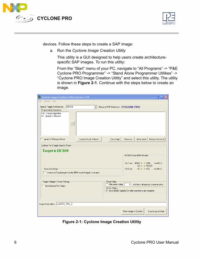
devices. Follow these steps to create a SAP image:a. Run the Cyclone Image Creation Utility
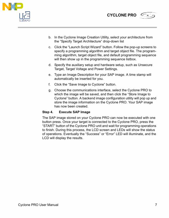
This utility is a GUI designed to help users create architecture-specific SAP images. To run this utility:From the “Start” menu of your PC, navigate to “All Programs” -> “P&E Cyclone PRO Programmer” -> “Stand Alone Programmer Utilities” -> “Cyclone PRO Image Creation Utility” and select this utility. The utility is shown in Figure 2-1. Continue with the steps below to create an image.
Figure 2-1: Cyclone Image Creation Utility
Cyclone PRO User Manual 7
CYCLONE PRO
b. In the Cyclone Image Creation Utility, select your architecture from the “Specify Target Architecture” drop-down list
c. Click the “Launch Script Wizard” button. Follow the pop-up screens to specify a programming algorithm and target object file. The program-ming algorithm, target object file, and default programming sequence will then show up in the programming sequence listbox.
d. Specify the auxiliary setup and hardware setup, such as Unsecure Target, Target Voltage and Power Settings.
e. Type an Image Description for your SAP image. A time stamp will automatically be inserted for you.
f. Click the “Save Image to Cyclone” button.
g. Choose the communications interface, select the Cyclone PRO to which the image will be saved, and then click the “Store Image to Cyclone” button. A backend image configuration utility will pop up and store the image information on the Cyclone PRO. Your SAP image has now been created.
Step 4. Execute SAP ImageThe SAP image stored on your Cyclone PRO can now be executed with one button press. Once your target is connected to the Cyclone PRO, press the “START” button of the Cyclone PRO unit and wait for programming operations to finish. During this process, the LCD screen and LEDs will show the status of operations. Eventually the “Success” or “Error” LED will illuminate, and the LCD will display the results.
8 Cyclone PRO User Manual
CYCLONE PRO
3 CYCLONE PRO HARDWAREThe following is an overview of the features and interfaces of the Cyclone PRO unit.
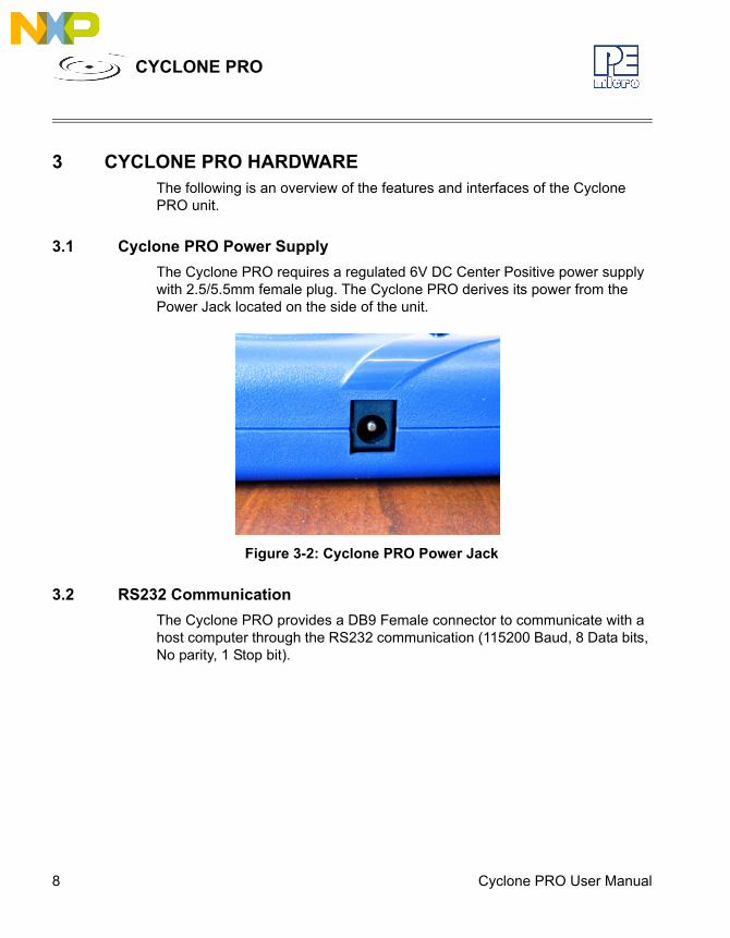
3.1 Cyclone PRO Power SupplyThe Cyclone PRO requires a regulated 6V DC Center Positive power supply with 2.5/5.5mm female plug. The Cyclone PRO derives its power from the Power Jack located on the side of the unit.
Figure 3-2: Cyclone PRO Power Jack
3.2 RS232 CommunicationThe Cyclone PRO provides a DB9 Female connector to communicate with a host computer through the RS232 communication (115200 Baud, 8 Data bits, No parity, 1 Stop bit).
Cyclone PRO User Manual 9
CYCLONE PRO
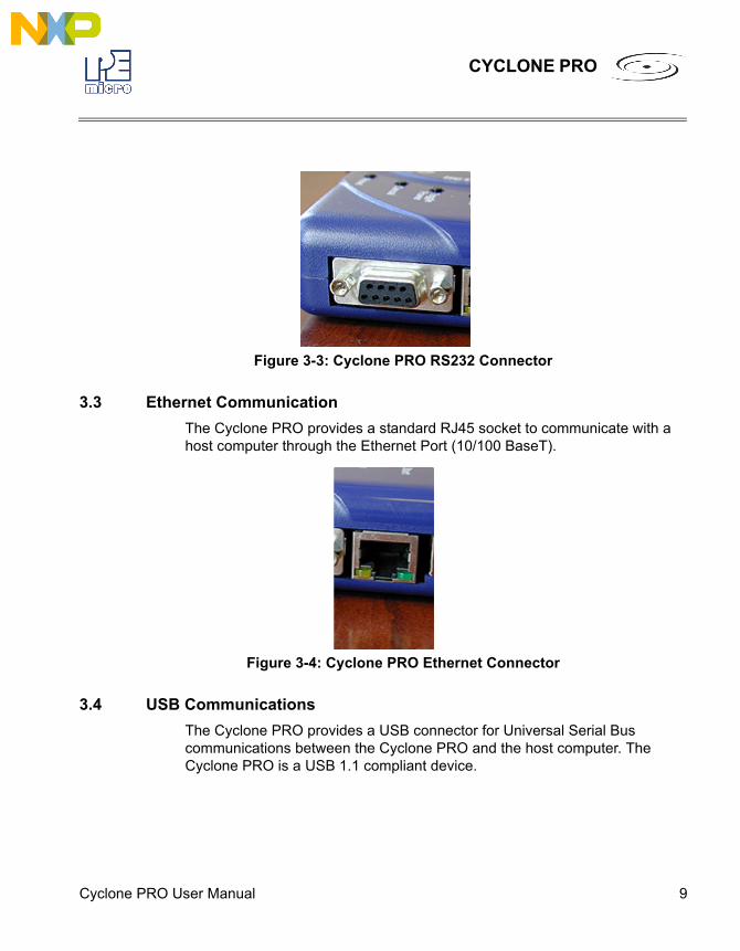
Figure 3-3: Cyclone PRO RS232 Connector
3.3 Ethernet CommunicationThe Cyclone PRO provides a standard RJ45 socket to communicate with a host computer through the Ethernet Port (10/100 BaseT).
Figure 3-4: Cyclone PRO Ethernet Connector
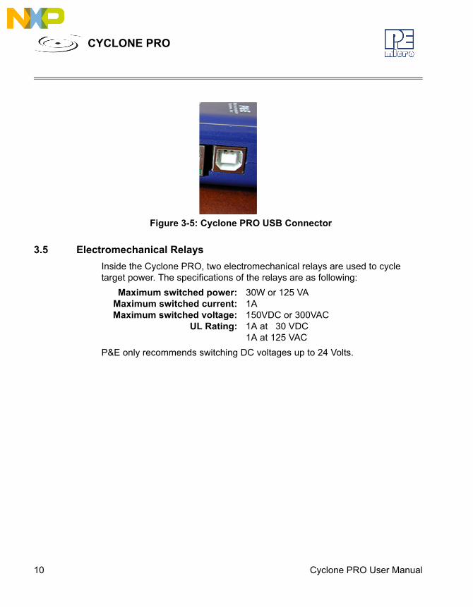
3.4 USB CommunicationsThe Cyclone PRO provides a USB connector for Universal Serial Bus communications between the Cyclone PRO and the host computer. The Cyclone PRO is a USB 1.1 compliant device.
10 Cyclone PRO User Manual
CYCLONE PRO
Figure 3-5: Cyclone PRO USB Connector
3.5 Electromechanical RelaysInside the Cyclone PRO, two electromechanical relays are used to cycle target power. The specifications of the relays are as following:
Maximum switched power: 30W or 125 VAMaximum switched current: 1AMaximum switched voltage: 150VDC or 300VAC
UL Rating: 1A at 30 VDC1A at 125 VAC
P&E only recommends switching DC voltages up to 24 Volts.
Cyclone PRO User Manual 11
CYCLONE PRO
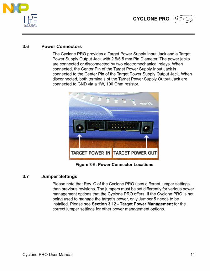
3.6 Power ConnectorsThe Cyclone PRO provides a Target Power Supply Input Jack and a Target Power Supply Output Jack with 2.5/5.5 mm Pin Diameter. The power jacks are connected or disconnected by two electromechanical relays. When connected, the Center Pin of the Target Power Supply Input Jack is connected to the Center Pin of the Target Power Supply Output Jack. When disconnected, both terminals of the Target Power Supply Output Jack are connected to GND via a 1W, 100 Ohm resistor.
Figure 3-6: Power Connector Locations
3.7 Jumper SettingsPlease note that Rev. C of the Cyclone PRO uses different jumper settings than previous revisions. The jumpers must be set differently for various power management options that the Cyclone PRO offers. If the Cyclone PRO is not being used to manage the target’s power, only Jumper 5 needs to be installed. Please see Section 3.12 - Target Power Management for the correct jumper settings for other power management options.
12 Cyclone PRO User Manual
CYCLONE PRO
3.8 Optional Oscillator (MON08 Only)The Cyclone PRO provides a software configurable 9.8304MHz or 4.1952 MHz oscillator clock signal to Pin 13 of the MON08 Connector. The user may use this clock signal to overdrive the target RC or crystal circuitry. If this signal is not used, just leave Pin 13 of the target MON08 header unconnected.Please note that if the target already uses an oscillator as its clock, the Cyclone PRO will NOT be able to overdrive it. The clock should have sufficient drive to be used with a target system even if the target system has an RC circuit or crystal connected.
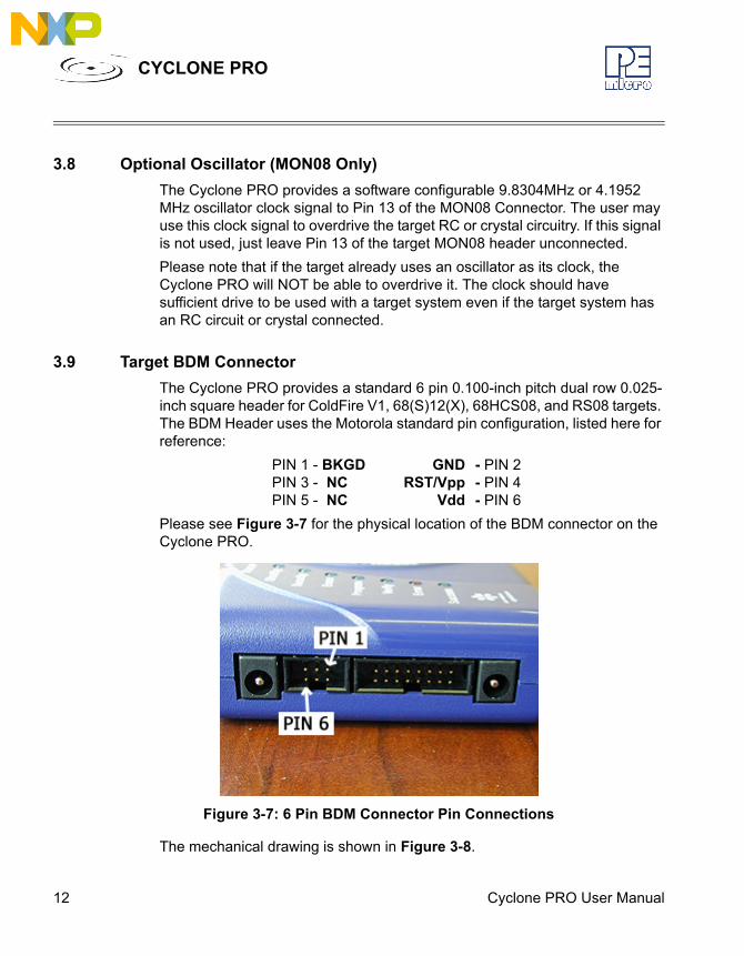
3.9 Target BDM ConnectorThe Cyclone PRO provides a standard 6 pin 0.100-inch pitch dual row 0.025-inch square header for ColdFire V1, 68(S)12(X), 68HCS08, and RS08 targets. The BDM Header uses the Motorola standard pin configuration, listed here for reference:
PIN 1 - BKGD GND - PIN 2PIN 3 - NC RST/Vpp - PIN 4PIN 5 - NC Vdd - PIN 6
Please see Figure 3-7 for the physical location of the BDM connector on the Cyclone PRO.
Figure 3-7: 6 Pin BDM Connector Pin Connections
The mechanical drawing is shown in Figure 3-8.
Cyclone PRO User Manual 13
CYCLONE PRO
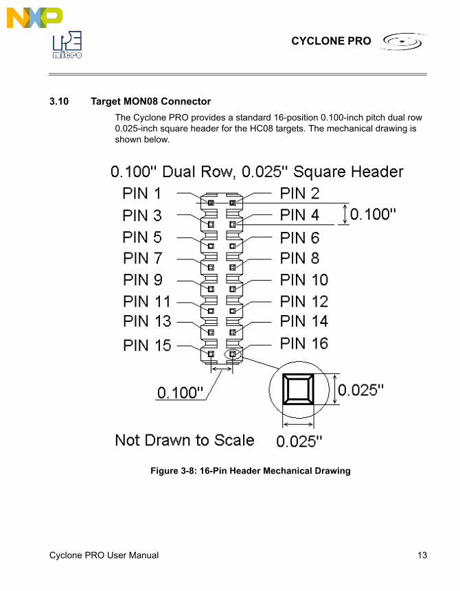
3.10 Target MON08 ConnectorThe Cyclone PRO provides a standard 16-position 0.100-inch pitch dual row 0.025-inch square header for the HC08 targets. The mechanical drawing is shown below.
Figure 3-8: 16-Pin Header Mechanical Drawing
14 Cyclone PRO User Manual
CYCLONE PRO
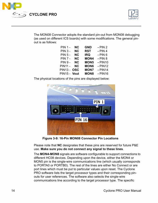
The MON08 Connector adopts the standard pin-out from MON08 debugging (as used on different ICS boards) with some modifications. The general pin-out is as follows:
PIN 1 - NC GND - PIN 2PIN 3 - NC RST - PIN 4PIN 5 - NC IRQ - PIN 6PIN 7 - NC MON4 - PIN 8PIN 9 - NC MON5 - PIN10PIN11 - NC MON6 - PIN12PIN13 - OSC MON7 - PIN14PIN15 - Vout MON8 - PIN16
The physical locations of the pins are displayed below:
Figure 3-9: 16-Pin MON08 Connector Pin Locations
Please note that NC designates that these pins are reserved for future P&E use. Make sure you do not connect any signal to these lines.The MON4-MON8 signals are software configurable to support connections to different HC08 devices. Depending upon the device, either the MON4 or MON5 pin is the single-wire communications line (which usually corresponds to PORTA0 or PORTB0). The rest of the lines are either No Connect or are port lines which must be put to particular values upon reset. The Cyclone PRO software lists the target processor types and their corresponding pin-outs for user references. The software also selects the single-wire communications line according to the target processor type. The specific
Cyclone PRO User Manual 15
CYCLONE PRO
pinouts for different HC08 devices are specified in the configuration software and also in CHAPTER 13 – TARGET MON08 HEADER PINOUTS.
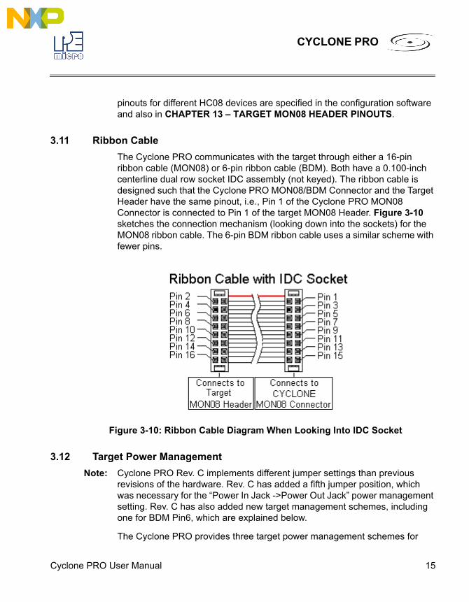
3.11 Ribbon CableThe Cyclone PRO communicates with the target through either a 16-pin ribbon cable (MON08) or 6-pin ribbon cable (BDM). Both have a 0.100-inch centerline dual row socket IDC assembly (not keyed). The ribbon cable is designed such that the Cyclone PRO MON08/BDM Connector and the Target Header have the same pinout, i.e., Pin 1 of the Cyclone PRO MON08 Connector is connected to Pin 1 of the target MON08 Header. Figure 3-10 sketches the connection mechanism (looking down into the sockets) for the MON08 ribbon cable. The 6-pin BDM ribbon cable uses a similar scheme with fewer pins.
Figure 3-10: Ribbon Cable Diagram When Looking Into IDC Socket
3.12 Target Power ManagementNote: Cyclone PRO Rev. C implements different jumper settings than previous
revisions of the hardware. Rev. C has added a fifth jumper position, which was necessary for the “Power In Jack ->Power Out Jack” power management setting. Rev. C has also added new target management schemes, including one for BDM Pin6, which are explained below.
The Cyclone PRO provides three target power management schemes for
16 Cyclone PRO User Manual
CYCLONE PRO
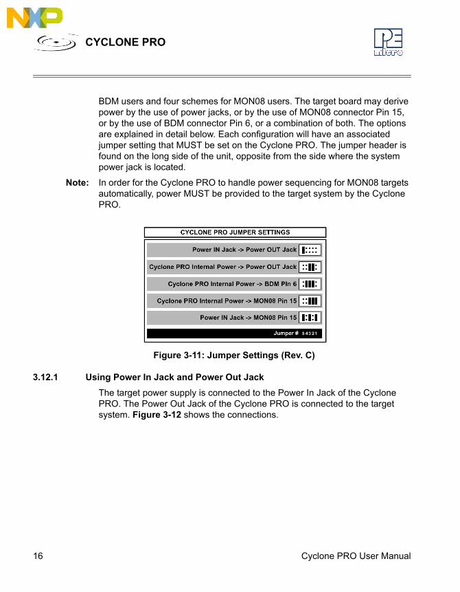
BDM users and four schemes for MON08 users. The target board may derive power by the use of power jacks, or by the use of MON08 connector Pin 15, or by the use of BDM connector Pin 6, or a combination of both. The options are explained in detail below. Each configuration will have an associated jumper setting that MUST be set on the Cyclone PRO. The jumper header is found on the long side of the unit, opposite from the side where the system power jack is located.
Note: In order for the Cyclone PRO to handle power sequencing for MON08 targets automatically, power MUST be provided to the target system by the Cyclone PRO.
Figure 3-11: Jumper Settings (Rev. C)
3.12.1 Using Power In Jack and Power Out JackThe target power supply is connected to the Power In Jack of the Cyclone PRO. The Power Out Jack of the Cyclone PRO is connected to the target system. Figure 3-12 shows the connections.

Cyclone PRO User Manual 17
CYCLONE PRO
Figure 3-12: Via Power In and Power Out Jacks of Cyclone PRO
All of the jumpers except Jumper 5 should be left open for this mode, as shown in Figure 3-13.
Note: This setting differs from the Rev. B Cyclone PRO, which requires no jumpers.
Figure 3-13: Jumper Settings for Target Power Connection via Power In and Power Out Jacks Of Cyclone PRO
Only Jumper 5 is installed.
3.12.2 Using Cyclone PRO Board Power and Power Out JackThe target power supply is not needed. The Power Out Jack of the Cyclone PRO will act as a center positive power supply to the target system. Figure 3-
18 Cyclone PRO User Manual
CYCLONE PRO
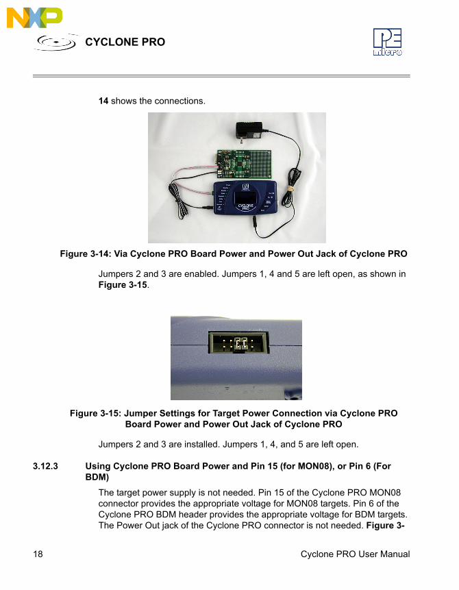
14 shows the connections.
Figure 3-14: Via Cyclone PRO Board Power and Power Out Jack of Cyclone PRO
Jumpers 2 and 3 are enabled. Jumpers 1, 4 and 5 are left open, as shown in Figure 3-15.
Figure 3-15: Jumper Settings for Target Power Connection via Cyclone PRO Board Power and Power Out Jack of Cyclone PRO
Jumpers 2 and 3 are installed. Jumpers 1, 4, and 5 are left open.
3.12.3 Using Cyclone PRO Board Power and Pin 15 (for MON08), or Pin 6 (For BDM)
The target power supply is not needed. Pin 15 of the Cyclone PRO MON08 connector provides the appropriate voltage for MON08 targets. Pin 6 of the Cyclone PRO BDM header provides the appropriate voltage for BDM targets. The Power Out jack of the Cyclone PRO connector is not needed. Figure 3-

Cyclone PRO User Manual 19
CYCLONE PRO
16 shows the connections.
Figure 3-16: Via Cyclone PRO Board Power and Pin 15 of Cyclone PRO MON08 Connector
Jumpers 1, 2, and 3 are all enabled, as shown in Figure 3-17.
Figure 3-17: Jumper Settings for Target Power Connection via Cyclone PRO Board Power and Pin 15 of Cyclone PRO MON08 Connector
20 Cyclone PRO User Manual
CYCLONE PRO
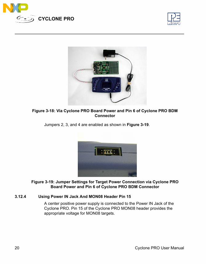
Figure 3-18: Via Cyclone PRO Board Power and Pin 6 of Cyclone PRO BDM Connector
Jumpers 2, 3, and 4 are enabled as shown in Figure 3-19..
Figure 3-19: Jumper Settings for Target Power Connection via Cyclone PRO Board Power and Pin 6 of Cyclone PRO BDM Connector
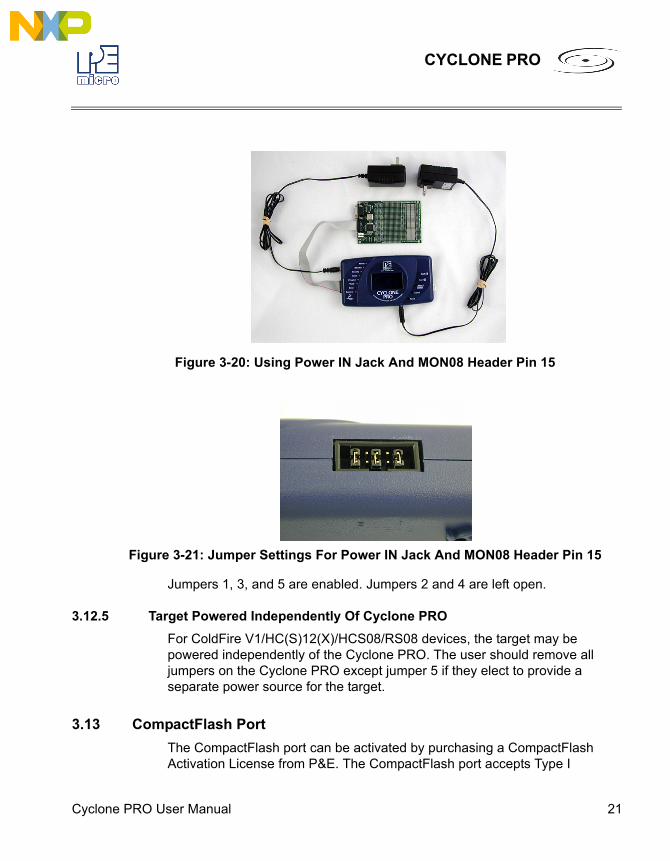
3.12.4 Using Power IN Jack And MON08 Header Pin 15A center positive power supply is connected to the Power IN Jack of the Cyclone PRO. Pin 15 of the Cyclone PRO MON08 header provides the appropriate voltage for MON08 targets.
Cyclone PRO User Manual 21
CYCLONE PRO
Figure 3-20: Using Power IN Jack And MON08 Header Pin 15
Figure 3-21: Jumper Settings For Power IN Jack And MON08 Header Pin 15
Jumpers 1, 3, and 5 are enabled. Jumpers 2 and 4 are left open.
3.12.5 Target Powered Independently Of Cyclone PROFor ColdFire V1/HC(S)12(X)/HCS08/RS08 devices, the target may be powered independently of the Cyclone PRO. The user should remove all jumpers on the Cyclone PRO except jumper 5 if they elect to provide a separate power source for the target.
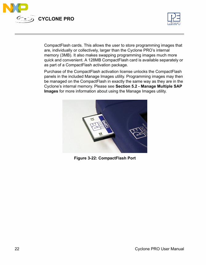
3.13 CompactFlash PortThe CompactFlash port can be activated by purchasing a CompactFlash Activation License from P&E. The CompactFlash port accepts Type I
22 Cyclone PRO User Manual
CYCLONE PRO
CompactFlash cards. This allows the user to store programming images that are, individually or collectively, larger than the Cyclone PRO’s internal memory (3MB). It also makes swapping programming images much more quick and convenient. A 128MB CompactFlash card is available separately or as part of a CompactFlash activation package.Purchase of the CompactFlash activation license unlocks the CompactFlash panels in the included Manage Images utility. Programming images may then be managed on the CompactFlash in exactly the same way as they are in the Cyclone’s internal memory. Please see Section 5.2 - Manage Multiple SAP Images for more information about using the Manage Images utility.
Figure 3-22: CompactFlash Port
Cyclone PRO User Manual 23
CYCLONE PRO
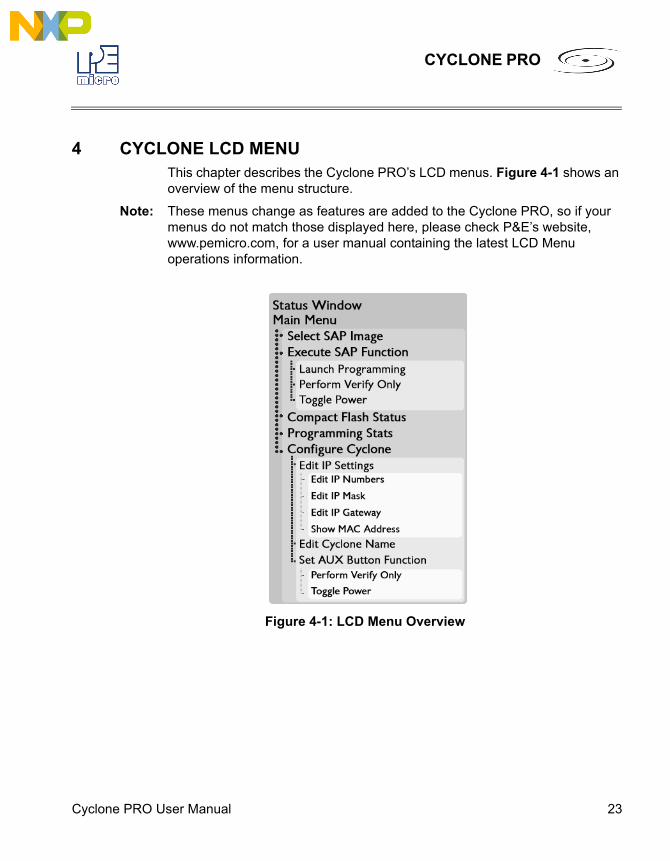
4 CYCLONE LCD MENUThis chapter describes the Cyclone PRO’s LCD menus. Figure 4-1 shows an overview of the menu structure.
Note: These menus change as features are added to the Cyclone PRO, so if your menus do not match those displayed here, please check P&E’s website, www.pemicro.com, for a user manual containing the latest LCD Menu operations information.
Figure 4-1: LCD Menu Overview
24 Cyclone PRO User Manual
CYCLONE PRO
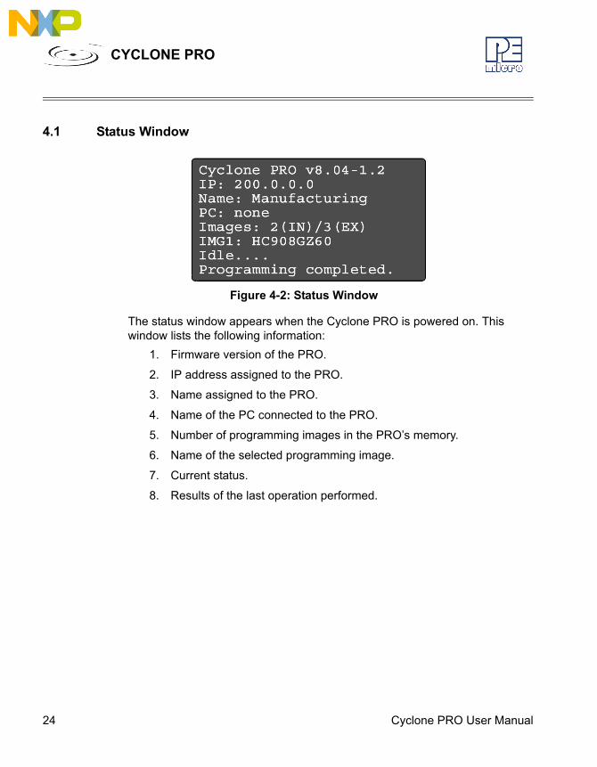
4.1 Status Window
Figure 4-2: Status Window
The status window appears when the Cyclone PRO is powered on. This window lists the following information:
1. Firmware version of the PRO.
2. IP address assigned to the PRO.
3. Name assigned to the PRO.
4. Name of the PC connected to the PRO.
5. Number of programming images in the PRO’s memory.
6. Name of the selected programming image.
7. Current status.
8. Results of the last operation performed.
Cyclone PRO User Manual 25
CYCLONE PRO
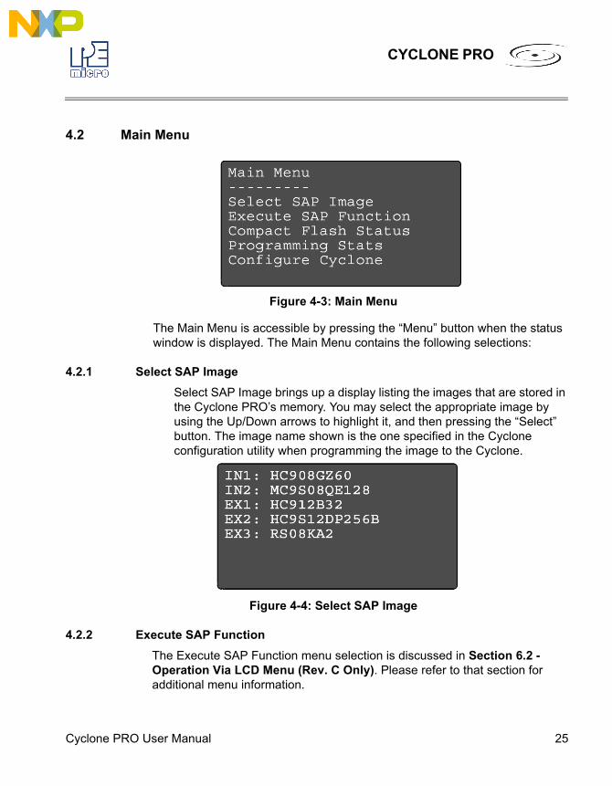
4.2 Main Menu
Figure 4-3: Main Menu
The Main Menu is accessible by pressing the “Menu” button when the status window is displayed. The Main Menu contains the following selections:
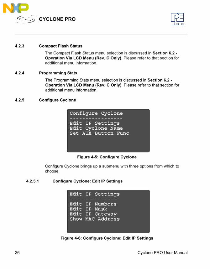
4.2.1 Select SAP ImageSelect SAP Image brings up a display listing the images that are stored in the Cyclone PRO’s memory. You may select the appropriate image by using the Up/Down arrows to highlight it, and then pressing the “Select” button. The image name shown is the one specified in the Cyclone configuration utility when programming the image to the Cyclone.
Figure 4-4: Select SAP Image
4.2.2 Execute SAP FunctionThe Execute SAP Function menu selection is discussed in Section 6.2 - Operation Via LCD Menu (Rev. C Only). Please refer to that section for additional menu information.
26 Cyclone PRO User Manual
CYCLONE PRO
4.2.3 Compact Flash StatusThe Compact Flash Status menu selection is discussed in Section 6.2 - Operation Via LCD Menu (Rev. C Only). Please refer to that section for additional menu information.
4.2.4 Programming StatsThe Programming Stats menu selection is discussed in Section 6.2 - Operation Via LCD Menu (Rev. C Only). Please refer to that section for additional menu information.
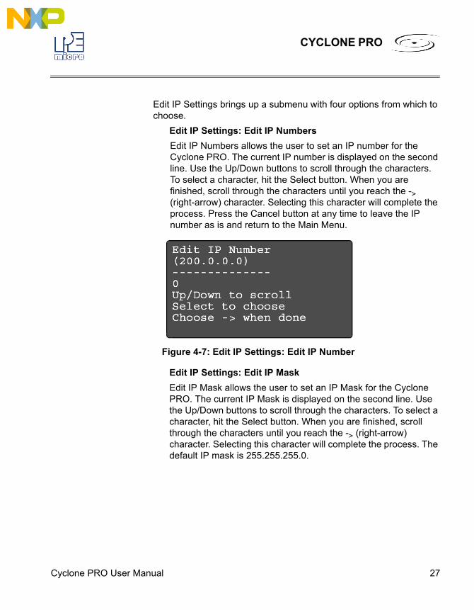
4.2.5 Configure Cyclone
Figure 4-5: Configure Cyclone
Configure Cyclone brings up a submenu with three options from which to choose.
4.2.5.1 Configure Cyclone: Edit IP Settings
Figure 4-6: Configure Cyclone: Edit IP Settings
Cyclone PRO User Manual 27
CYCLONE PRO
Edit IP Settings brings up a submenu with four options from which to choose.
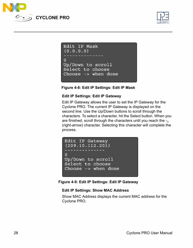
Edit IP Settings: Edit IP NumbersEdit IP Numbers allows the user to set an IP number for the Cyclone PRO. The current IP number is displayed on the second line. Use the Up/Down buttons to scroll through the characters. To select a character, hit the Select button. When you are finished, scroll through the characters until you reach the -> (right-arrow) character. Selecting this character will complete the process. Press the Cancel button at any time to leave the IP number as is and return to the Main Menu.
Figure 4-7: Edit IP Settings: Edit IP Number
Edit IP Settings: Edit IP MaskEdit IP Mask allows the user to set an IP Mask for the Cyclone PRO. The current IP Mask is displayed on the second line. Use the Up/Down buttons to scroll through the characters. To select a character, hit the Select button. When you are finished, scroll through the characters until you reach the -> (right-arrow) character. Selecting this character will complete the process. The default IP mask is 255.255.255.0.
28 Cyclone PRO User Manual
CYCLONE PRO
Figure 4-8: Edit IP Settings: Edit IP Mask
Edit IP Settings: Edit IP GatewayEdit IP Gateway allows the user to set the IP Gateway for the Cyclone PRO. The current IP Gateway is displayed on the second line. Use the Up/Down buttons to scroll through the characters. To select a character, hit the Select button. When you are finished, scroll through the characters until you reach the -> (right-arrow) character. Selecting this character will complete the process.
Figure 4-9: Edit IP Settings: Edit IP Gateway
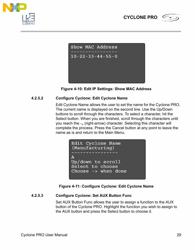
Edit IP Settings: Show MAC AddressShow MAC Address displays the current MAC address for the Cyclone PRO.
Cyclone PRO User Manual 29
CYCLONE PRO
Figure 4-10: Edit IP Settings: Show MAC Address
4.2.5.2 Configure Cyclone: Edit Cyclone NameEdit Cyclone Name allows the user to set the name for the Cyclone PRO. The current name is displayed on the second line. Use the Up/Down buttons to scroll through the characters. To select a character, hit the Select button. When you are finished, scroll through the characters until you reach the -> (right-arrow) character. Selecting this character will complete the process. Press the Cancel button at any point to leave the name as is and return to the Main Menu.
Figure 4-11: Configure Cyclone: Edit Cyclone Name
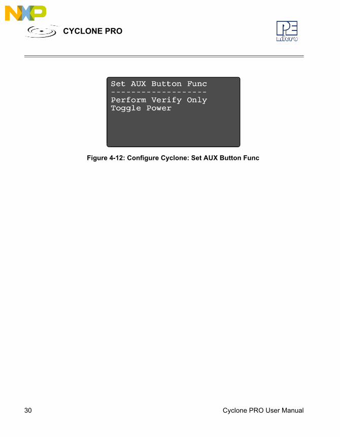
4.2.5.3 Configure Cyclone: Set AUX Button FuncSet AUX Button Func allows the user to assign a function to the AUX button of the Cyclone PRO. Highlight the function you wish to assign to the AUX button and press the Select button to choose it.
30 Cyclone PRO User Manual
CYCLONE PRO
Figure 4-12: Configure Cyclone: Set AUX Button Func
Cyclone PRO User Manual 31
CYCLONE PRO
5 STAND-ALONE PROGRAMMER CONFIGURATIONThe Cyclone PRO may act as a Stand-Alone In-Circuit Programmer for HC08, HCS08, RS08, HC(S)12(X), and ColdFire V1 targets. A simple user interface, CREATEIMAGE.EXE, is provided for configuring the Cyclone PRO.
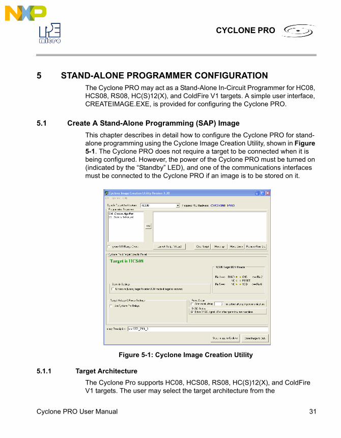
5.1 Create A Stand-Alone Programming (SAP) ImageThis chapter describes in detail how to configure the Cyclone PRO for stand-alone programming using the Cyclone Image Creation Utility, shown in Figure 5-1. The Cyclone PRO does not require a target to be connected when it is being configured. However, the power of the Cyclone PRO must be turned on (indicated by the “Standby” LED), and one of the communications interfaces must be connected to the Cyclone PRO if an image is to be stored on it.
Figure 5-1: Cyclone Image Creation Utility
5.1.1 Target ArchitectureThe Cyclone Pro supports HC08, HCS08, RS08, HC(S)12(X), and ColdFire V1 targets. The user may select the target architecture from the
32 Cyclone PRO User Manual
CYCLONE PRO
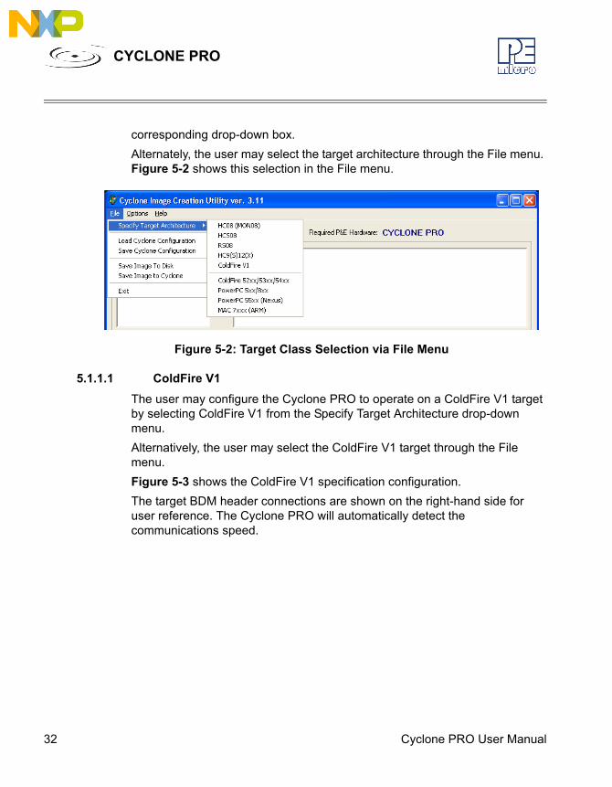
corresponding drop-down box.Alternately, the user may select the target architecture through the File menu. Figure 5-2 shows this selection in the File menu.
Figure 5-2: Target Class Selection via File Menu
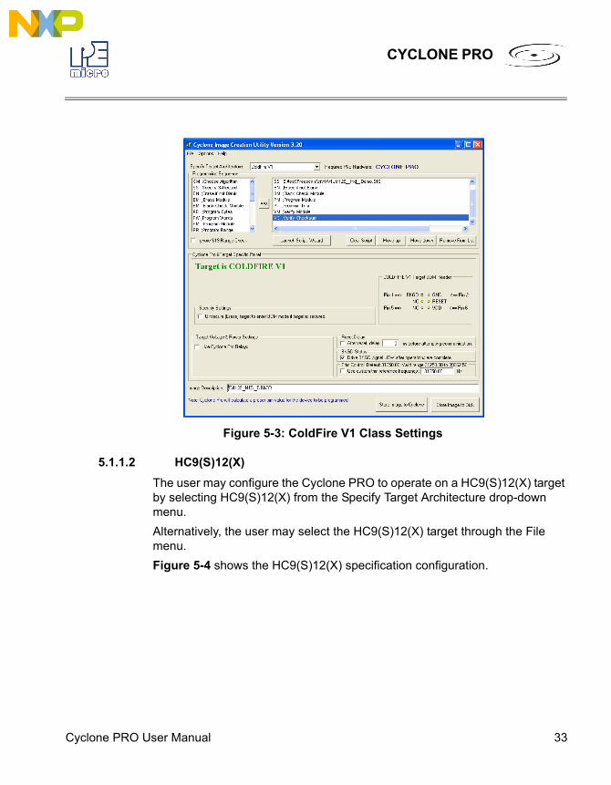
5.1.1.1 ColdFire V1The user may configure the Cyclone PRO to operate on a ColdFire V1 target by selecting ColdFire V1 from the Specify Target Architecture drop-down menu.Alternatively, the user may select the ColdFire V1 target through the File menu.Figure 5-3 shows the ColdFire V1 specification configuration.The target BDM header connections are shown on the right-hand side for user reference. The Cyclone PRO will automatically detect the communications speed.
Cyclone PRO User Manual 33
CYCLONE PRO
Figure 5-3: ColdFire V1 Class Settings
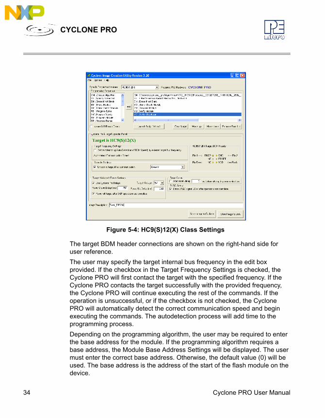
5.1.1.2 HC9(S)12(X)The user may configure the Cyclone PRO to operate on a HC9(S)12(X) target by selecting HC9(S)12(X) from the Specify Target Architecture drop-down menu.Alternatively, the user may select the HC9(S)12(X) target through the File menu.Figure 5-4 shows the HC9(S)12(X) specification configuration.
34 Cyclone PRO User Manual
CYCLONE PRO
Figure 5-4: HC9(S)12(X) Class Settings
The target BDM header connections are shown on the right-hand side for user reference.The user may specify the target internal bus frequency in the edit box provided. If the checkbox in the Target Frequency Settings is checked, the Cyclone PRO will first contact the target with the specified frequency. If the Cyclone PRO contacts the target successfully with the provided frequency, the Cyclone PRO will continue executing the rest of the commands. If the operation is unsuccessful, or if the checkbox is not checked, the Cyclone PRO will automatically detect the correct communication speed and begin executing the commands. The autodetection process will add time to the programming process.Depending on the programming algorithm, the user may be required to enter the base address for the module. If the programming algorithm requires a base address, the Module Base Address Settings will be displayed. The user must enter the correct base address. Otherwise, the default value (0) will be used. The base address is the address of the start of the flash module on the device.
Cyclone PRO User Manual 35
CYCLONE PRO
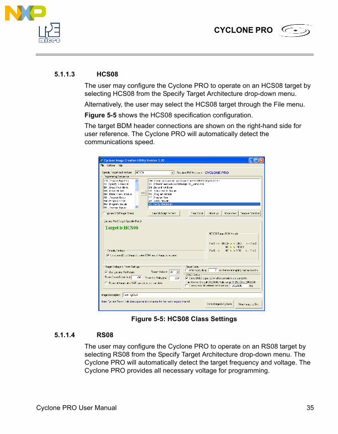
5.1.1.3 HCS08The user may configure the Cyclone PRO to operate on an HCS08 target by selecting HCS08 from the Specify Target Architecture drop-down menu.Alternatively, the user may select the HCS08 target through the File menu.Figure 5-5 shows the HCS08 specification configuration.The target BDM header connections are shown on the right-hand side for user reference. The Cyclone PRO will automatically detect the communications speed.
Figure 5-5: HCS08 Class Settings
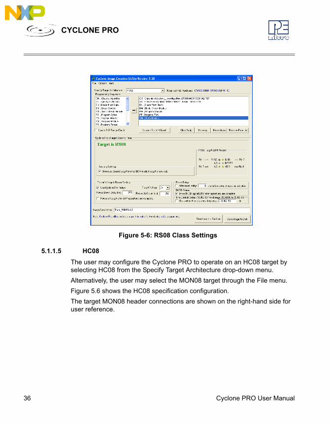
5.1.1.4 RS08The user may configure the Cyclone PRO to operate on an RS08 target by selecting RS08 from the Specify Target Architecture drop-down menu. The Cyclone PRO will automatically detect the target frequency and voltage. The Cyclone PRO provides all necessary voltage for programming.
36 Cyclone PRO User Manual
CYCLONE PRO
Figure 5-6: RS08 Class Settings
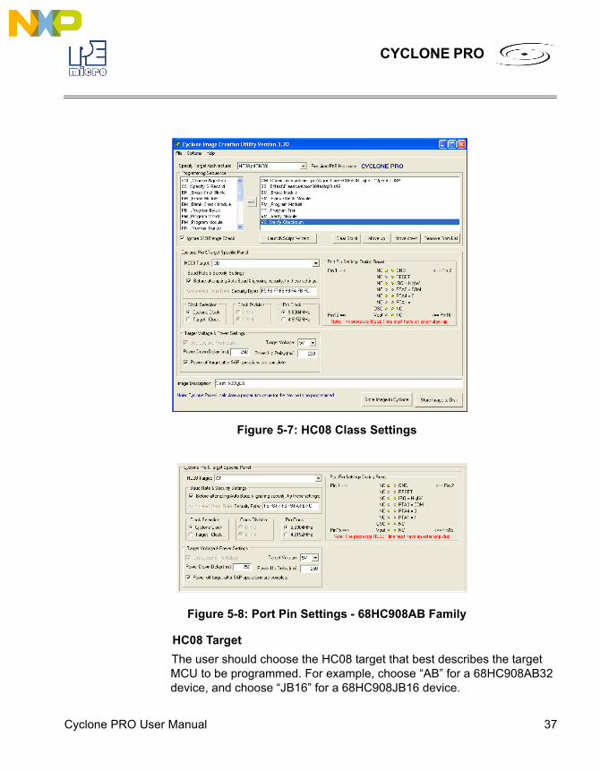
5.1.1.5 HC08The user may configure the Cyclone PRO to operate on an HC08 target by selecting HC08 from the Specify Target Architecture drop-down menu.Alternatively, the user may select the MON08 target through the File menu.Figure 5.6 shows the HC08 specification configuration.The target MON08 header connections are shown on the right-hand side for user reference.
Cyclone PRO User Manual 37
CYCLONE PRO
Figure 5-7: HC08 Class Settings
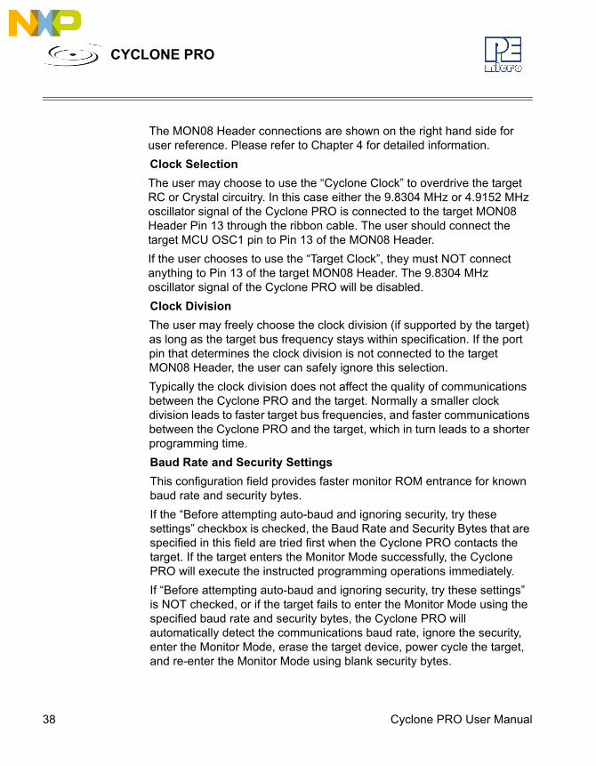
Figure 5-8: Port Pin Settings - 68HC908AB Family
HC08 TargetThe user should choose the HC08 target that best describes the target MCU to be programmed. For example, choose “AB” for a 68HC908AB32 device, and choose “JB16” for a 68HC908JB16 device.
38 Cyclone PRO User Manual
CYCLONE PRO
The MON08 Header connections are shown on the right hand side for user reference. Please refer to Chapter 4 for detailed information.Clock SelectionThe user may choose to use the “Cyclone Clock” to overdrive the target RC or Crystal circuitry. In this case either the 9.8304 MHz or 4.9152 MHz oscillator signal of the Cyclone PRO is connected to the target MON08 Header Pin 13 through the ribbon cable. The user should connect the target MCU OSC1 pin to Pin 13 of the MON08 Header.If the user chooses to use the “Target Clock”, they must NOT connect anything to Pin 13 of the target MON08 Header. The 9.8304 MHz oscillator signal of the Cyclone PRO will be disabled.Clock DivisionThe user may freely choose the clock division (if supported by the target) as long as the target bus frequency stays within specification. If the port pin that determines the clock division is not connected to the target MON08 Header, the user can safely ignore this selection.Typically the clock division does not affect the quality of communications between the Cyclone PRO and the target. Normally a smaller clock division leads to faster target bus frequencies, and faster communications between the Cyclone PRO and the target, which in turn leads to a shorter programming time.Baud Rate and Security SettingsThis configuration field provides faster monitor ROM entrance for known baud rate and security bytes.If the “Before attempting auto-baud and ignoring security, try these settings” checkbox is checked, the Baud Rate and Security Bytes that are specified in this field are tried first when the Cyclone PRO contacts the target. If the target enters the Monitor Mode successfully, the Cyclone PRO will execute the instructed programming operations immediately.If “Before attempting auto-baud and ignoring security, try these settings” is NOT checked, or if the target fails to enter the Monitor Mode using the specified baud rate and security bytes, the Cyclone PRO will automatically detect the communications baud rate, ignore the security, enter the Monitor Mode, erase the target device, power cycle the target, and re-enter the Monitor Mode using blank security bytes.
Cyclone PRO User Manual 39
CYCLONE PRO
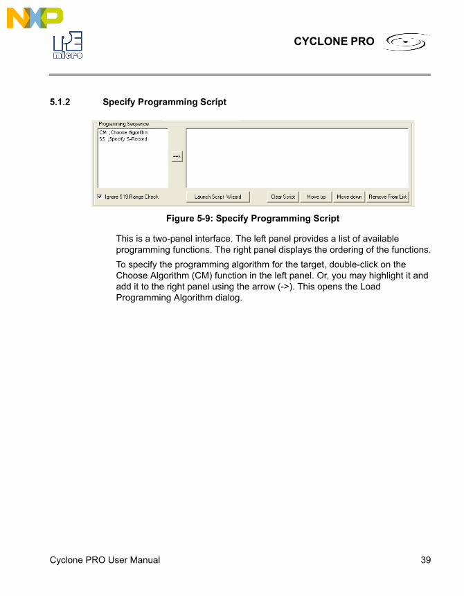
5.1.2 Specify Programming Script
Figure 5-9: Specify Programming Script
This is a two-panel interface. The left panel provides a list of available programming functions. The right panel displays the ordering of the functions.To specify the programming algorithm for the target, double-click on the Choose Algorithm (CM) function in the left panel. Or, you may highlight it and add it to the right panel using the arrow (->). This opens the Load Programming Algorithm dialog.
40 Cyclone PRO User Manual
CYCLONE PRO
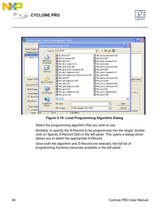
Figure 5-10: Load Programming Algorithm Dialog
Select the programming algorithm that you wish to use.Similarly, to specify the S-Record to be programmed into the target, double-click on Specify S-Record (SS) in the left panel. This opens a dialog which allows you to select the appropriate S-Record.Once both the algorithm and S-Record are selected, the full list of programming functions becomes available in the left panel.
Cyclone PRO User Manual 41
CYCLONE PRO
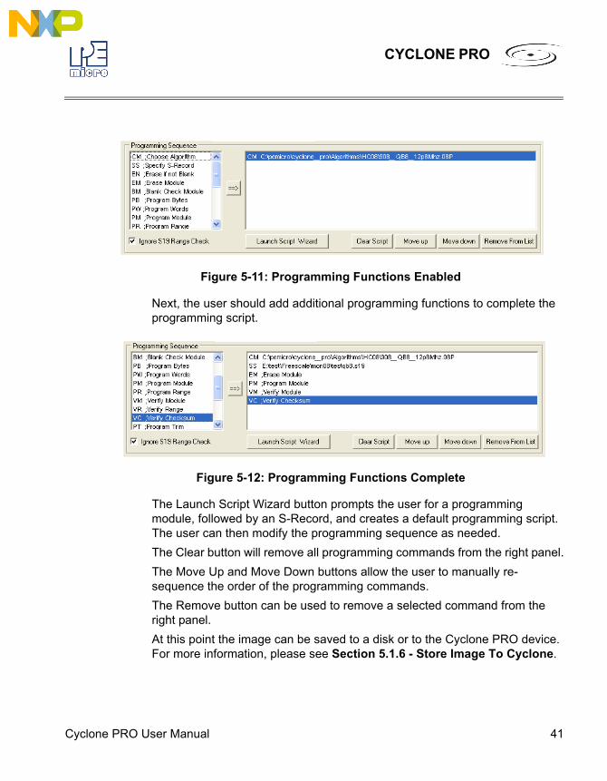
Figure 5-11: Programming Functions Enabled
Next, the user should add additional programming functions to complete the programming script.
Figure 5-12: Programming Functions Complete
The Launch Script Wizard button prompts the user for a programming module, followed by an S-Record, and creates a default programming script. The user can then modify the programming sequence as needed.The Clear button will remove all programming commands from the right panel.The Move Up and Move Down buttons allow the user to manually re-sequence the order of the programming commands.The Remove button can be used to remove a selected command from the right panel.At this point the image can be saved to a disk or to the Cyclone PRO device. For more information, please see Section 5.1.6 - Store Image To Cyclone.
42 Cyclone PRO User Manual
CYCLONE PRO
5.1.3 Programming Operations
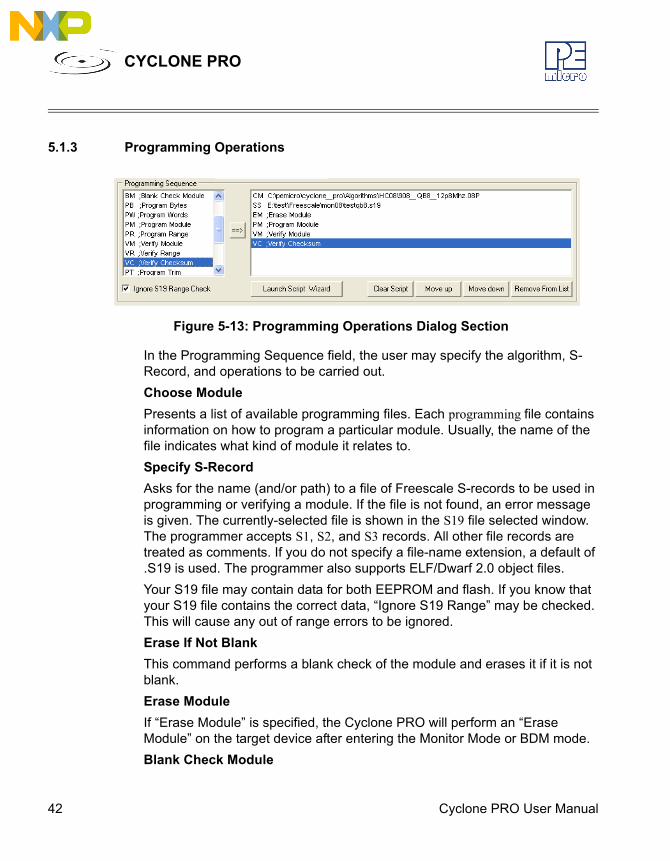
Figure 5-13: Programming Operations Dialog Section
In the Programming Sequence field, the user may specify the algorithm, S-Record, and operations to be carried out.Choose ModulePresents a list of available programming files. Each programming file contains information on how to program a particular module. Usually, the name of the file indicates what kind of module it relates to.Specify S-RecordAsks for the name (and/or path) to a file of Freescale S-records to be used in programming or verifying a module. If the file is not found, an error message is given. The currently-selected file is shown in the S19 file selected window. The programmer accepts S1, S2, and S3 records. All other file records are treated as comments. If you do not specify a file-name extension, a default of .S19 is used. The programmer also supports ELF/Dwarf 2.0 object files.Your S19 file may contain data for both EEPROM and flash. If you know that your S19 file contains the correct data, “Ignore S19 Range” may be checked. This will cause any out of range errors to be ignored.Erase If Not BlankThis command performs a blank check of the module and erases it if it is not blank.Erase ModuleIf “Erase Module” is specified, the Cyclone PRO will perform an “Erase Module” on the target device after entering the Monitor Mode or BDM mode.Blank Check Module
Cyclone PRO User Manual 43
CYCLONE PRO
If “Blank Check Module” is checked, the Cyclone PRO will perform a “Blank Check Module” on the target device.Program BytesPrompts for a starting address, which must be in the module. You are then asked to enter in hexadecimal a byte to be programmed into the current location. Clicking the OK button will automatically advance to the next data byte location.Program WordsPrompts for a starting address, which must be in the module. You are then asked to enter in hexadecimal a word to be programmed into the current location. Clicking the OK button will automatically advance to the next data word location.Program ModuleFor this command to work, you must have previously selected an S-record file. Verify ModuleFor this command to work, you must have previously selected an S-record file. Verify ChecksumThis command verifies the module content via a CRC calculation.Choose Serial FileThis command becomes available once a programming algorithm is selected. It specifies the serial file that holds the serial numbers to be programmed to the target. Please reference CHAPTER 12 – AUTOMATIC SERIAL NUMBER MECHANISM for more information about programming serial numbers.Program Serial NumberThis command becomes available once a programming algorithm is selected. It will instruct the Cyclone PRO to program the serial number to the target once executed. As with other commands, the serial number will not be programmed until the SAP operations are carried out. Please reference CHAPTER 12 – AUTOMATIC SERIAL NUMBER MECHANISM for more information about programming serial numbers.
44 Cyclone PRO User Manual
CYCLONE PRO
5.1.4 Target Voltage and Power SettingsA user may elect to use Cyclone PRO to supply power to the target (and this is a requirement for HC908 targets). In this case, the Target Voltage specifies the target MCU I/O voltage level.The user needs to take into account the power discharge time for the Power Down delay. The reset driver delays, power stabilization time, and the target clock stabilization time should be considered for the Power Up delay.A checkbox is available for a user to instruct the Cyclone PRO to turn off target power after SAP operations. If unchecked, the target power will remain on.For architectures other than HC908, options are available for the user to provide Reset Delay if some reset monitoring devices are used, and to determine whether to drive the BKGD signal to GND after operations are complete to assist programming the next target.
5.1.5 Image DescriptionThe Cyclone PRO Configuration Utility allows the user to summarize the purpose of current configuration for future reference. The description will be either programmed into the Cyclone PRO or saved into an encrypted file.The image description will appear on the LCD screen for image identification. Since the LCD can display up to 16 characters, it is recommended to keep the description concise.This field will not affect the Cyclone PRO’s operations with the target.
5.1.6 Store Image To Cyclone“Store Image to Cyclone” allows the current configuration to be programmed into the Cyclone PRO. The Cyclone PRO will then be ready for operations.
Cyclone PRO User Manual 45
CYCLONE PRO
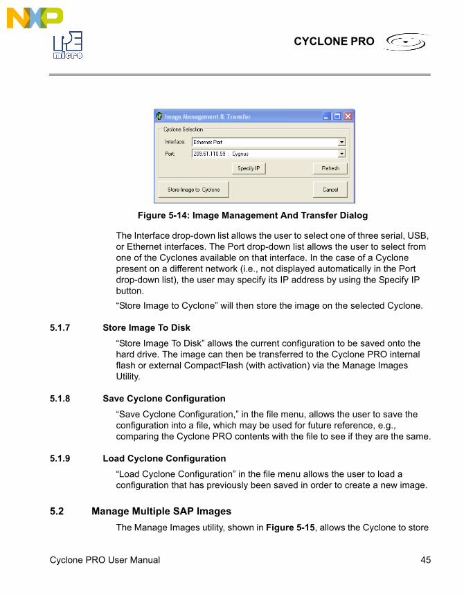
Figure 5-14: Image Management And Transfer Dialog
The Interface drop-down list allows the user to select one of three serial, USB, or Ethernet interfaces. The Port drop-down list allows the user to select from one of the Cyclones available on that interface. In the case of a Cyclone present on a different network (i.e., not displayed automatically in the Port drop-down list), the user may specify its IP address by using the Specify IP button.“Store Image to Cyclone” will then store the image on the selected Cyclone.
5.1.7 Store Image To Disk“Store Image To Disk” allows the current configuration to be saved onto the hard drive. The image can then be transferred to the Cyclone PRO internal flash or external CompactFlash (with activation) via the Manage Images Utility.
5.1.8 Save Cyclone Configuration“Save Cyclone Configuration,” in the file menu, allows the user to save the configuration into a file, which may be used for future reference, e.g., comparing the Cyclone PRO contents with the file to see if they are the same.
5.1.9 Load Cyclone Configuration“Load Cyclone Configuration” in the file menu allows the user to load a configuration that has previously been saved in order to create a new image.
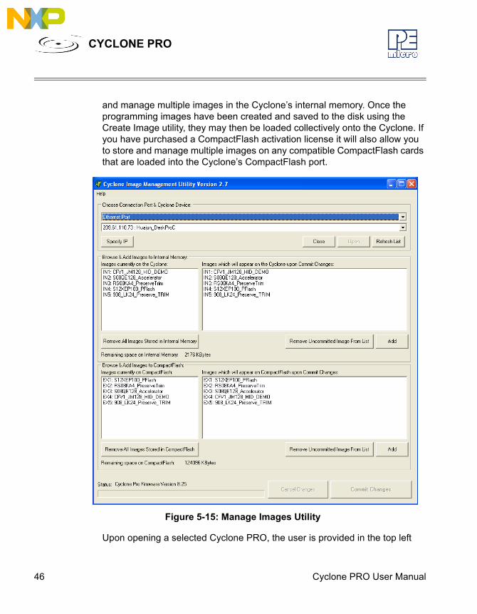
5.2 Manage Multiple SAP ImagesThe Manage Images utility, shown in Figure 5-15, allows the Cyclone to store
46 Cyclone PRO User Manual
CYCLONE PRO
and manage multiple images in the Cyclone’s internal memory. Once the programming images have been created and saved to the disk using the Create Image utility, they may then be loaded collectively onto the Cyclone. If you have purchased a CompactFlash activation license it will also allow you to store and manage multiple images on any compatible CompactFlash cards that are loaded into the Cyclone’s CompactFlash port.
Figure 5-15: Manage Images Utility
Upon opening a selected Cyclone PRO, the user is provided in the top left
Cyclone PRO User Manual 47
CYCLONE PRO
panel with a list of the images currently on the unit’s internal memory. If the CompactFlash license has been activated, a list of images on any connected CompactFlash card will also be displayed in the bottom left panel. The panels to the right can be used to add or delete additional images by using the Add and Remove buttons beneath each panel. Once the images that you wish to load appear in the panels to the right, you must press “Commit Changes” to load the Cyclone accordingly. No changes made to the Cyclone PRO until the “Commit Changes” button is pressed.
Note: Any images that are already stored on the Cyclone PRO or CompactFlash can only be removed by using the corresponding “Remove All Images...” button.
5.2.1 Optional CompactFlash Activation LicenseThe CompactFlash Activation License is a license key, available for purchase separately, which activates the Manage Images Utility and enables it to be used with the Cyclone’s CompactFlash card interface. Activation of the CompactFlash interface allows for programming of larger datasets and for the storage of multiple programming images on a CompactFlash card.For more details, please refer to Section 3.13 - CompactFlash Port.
48 Cyclone PRO User Manual
CYCLONE PRO
6 STAND-ALONE PROGRAMMER MANUAL CONTROLThe Cyclone PRO must be configured before it may serve as a Stand-Alone Programmer for HC08, HCS08, RS08, HC(S)12(X), ColdFire V1 targets. The user may manually control the Cyclone PRO: via the buttons/LEDs, LCD menu, or via PC software. The target power management schemes remain the same for each control method.
6.1 Operation Via Cyclone PRO ButtonsThere are five (5) buttons on the top of the Cyclone PRO which are used for stand-alone programming and to navigate the LCD menus. They are specified as follows.Button FunctionSTART / Start executing the tasks pre-configured into the
Cyclone PRO. Menu Mode: Navigate upwards in LCD menu.
AUX / Perform auxiliary function (stand-alone verification).Menu Mode: Navigate downwards in LCD menu.
MENU / [SELECT] Toggles ON/OFF the Target Board Power.Menu Mode: Select highlighted item in LCD menu.
CANCEL Cancel the tasks being executed and go back to the standby state.
RESET Hardware reset of the Cyclone PRO.
6.1.1 Cyclone PRO LED IndicatorsThe Cyclone PRO has eight (8) LEDs to indicate the current operation stage.LED FUNCTIONPower Indicates that the target board power is connected.Standby The Cyclone PRO is waiting for instructions.Security The Cyclone PRO is trying to pass the target security
and enter monitor mode (for MON08 only).Erase The Cyclone PRO is erasing the target Flash/
EEPROM.Program The Cyclone PRO is programming the target Flash/
Cyclone PRO User Manual 49
CYCLONE PRO
EEPROM.Verify The Cyclone PRO is verifying that the contents
programmed.Error The Cyclone PRO failed to execute the functions as
instructed.Success The Cyclone PRO executed the functions
successfully.
6.1.2 Procedure via Buttons and LEDsThe following steps must be followed in order for the Cyclone PRO to operate properly after the Cyclone PRO has been configured:
1. Turn off the target power supply if the “POWER IN” Jack is adopted.
2. Turn off the Cyclone PRO board power.
3. Set the correct Jumper settings.
4. Connect the target power supply to the “POWER IN” Jack, if applica-ble.
5. Connect the “POWER OUT” Jack to the target board power, if appli-cable.
6. Connect the MON08 Header Ribbon Cable to the target MON08 port, or the BDM Header Ribbon Cable to the target BDM port.
7. Turn on the Cyclone PRO board power.
8. Turn on the target power supply, if applicable.
9. Press the “START” push button on the Cyclone PRO. You will see the LEDs light up as specific functions are being executed.
When the “Success” LED lights up, you have successfully programmed your target.
6.1.3 ExampleWhen the Cyclone PRO is powered up, the Standby LED is turned on. After the user programs the contents and procedures into the Cyclone PRO on-board flash, the Cyclone PRO may be used as a Stand-Alone Programmer. Suppose the user wants to perform the following instructions for a 68HC908 target: 1) Erase Module
50 Cyclone PRO User Manual
CYCLONE PRO
2) Blank Check Module3) Program Module4) Verify Module. When the Start Button is pressed, the “Target Power On” LED will turn on, indicating that the Cyclone PRO is powering up the target board. Then the Standby LED will turn off and the Security LED will turn on. Here, if the target flash needs to be erased first to bypass the security, the Security LED will turn off and the Erasing LED will turn on. When the Erasing LED turns off, the Cyclone PRO attempts to pass security again. Then, when the Cyclone PRO starts programming the module, the “Programming” LED is illuminated. After this is done, the “Programming” LED is turned off and the “Verifying” LED is turned on, designating that the Cyclone PRO is verifying the contents just programmed into the target.Finally, if these operations have been performed successfully, the “Success” LED and the “Standby” LED are illuminated. One stand-alone programming cycle has just been completed.
6.2 Operation Via LCD Menu (Rev. C Only)Rev. C of the Cyclone PRO may be operated by making selections from the LCD menu. This section describes the layout of the menus and the functions that each may be used to perform.
Cyclone PRO User Manual 51
CYCLONE PRO
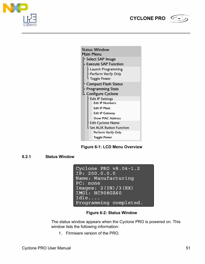
Figure 6-1: LCD Menu Overview
6.2.1 Status Window
Figure 6-2: Status Window
The status window appears when the Cyclone PRO is powered on. This window lists the following information:
1. Firmware version of the PRO.
52 Cyclone PRO User Manual
CYCLONE PRO
2. IP address assigned to the PRO.
3. Name assigned to the PRO.
4. Name of the PC connected to the PRO.
5. Number of programming images in the PRO’s memory.
6. Name of the selected programming image.
7. Current status.
8. Results of the last operation performed.
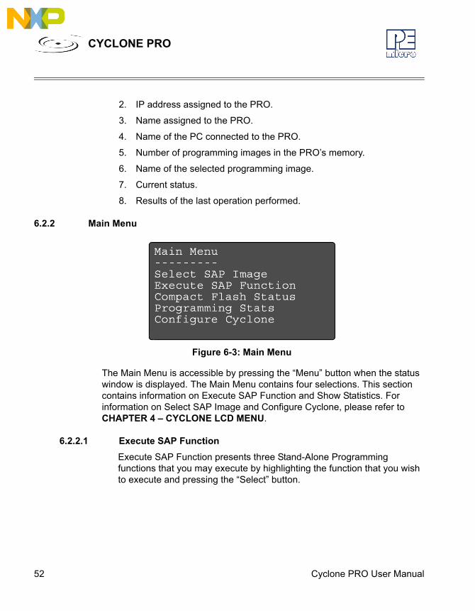
6.2.2 Main Menu
Figure 6-3: Main Menu
The Main Menu is accessible by pressing the “Menu” button when the status window is displayed. The Main Menu contains four selections. This section contains information on Execute SAP Function and Show Statistics. For information on Select SAP Image and Configure Cyclone, please refer to CHAPTER 4 – CYCLONE LCD MENU.
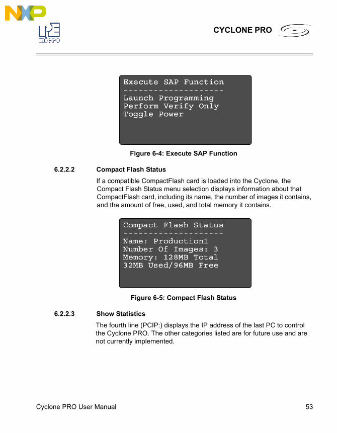
6.2.2.1 Execute SAP FunctionExecute SAP Function presents three Stand-Alone Programming functions that you may execute by highlighting the function that you wish to execute and pressing the “Select” button.
Cyclone PRO User Manual 53
CYCLONE PRO
Figure 6-4: Execute SAP Function
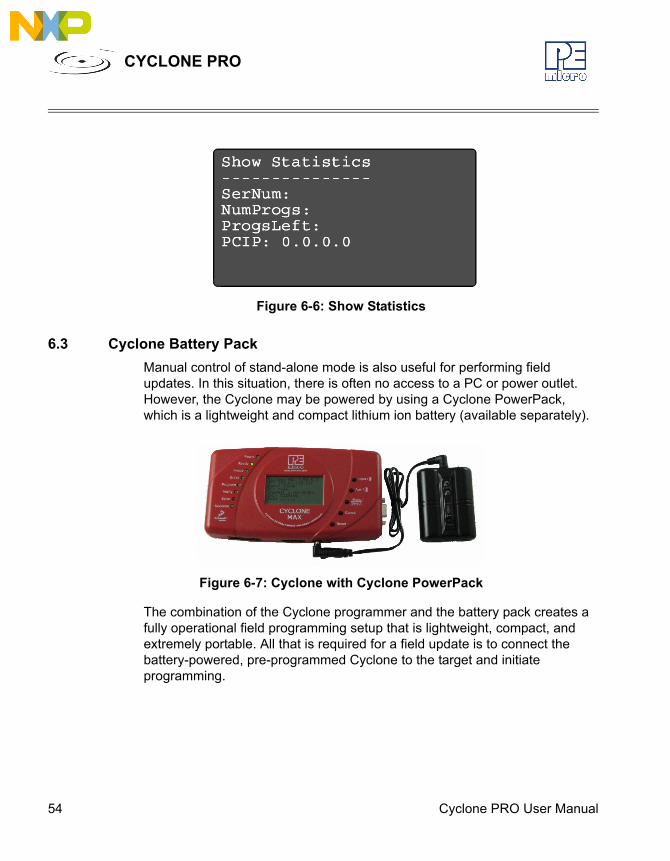
6.2.2.2 Compact Flash StatusIf a compatible CompactFlash card is loaded into the Cyclone, the Compact Flash Status menu selection displays information about that CompactFlash card, including its name, the number of images it contains, and the amount of free, used, and total memory it contains.
Figure 6-5: Compact Flash Status
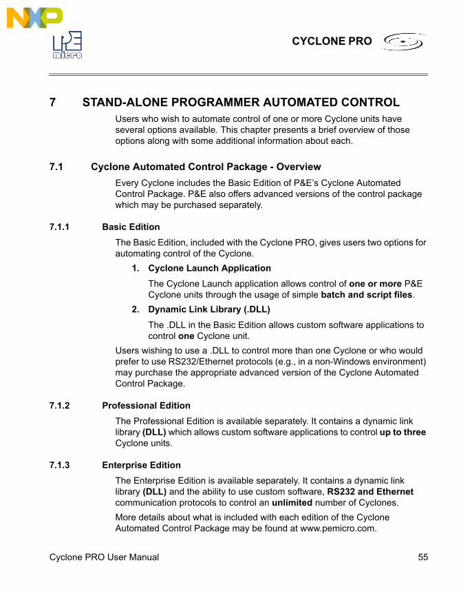
6.2.2.3 Show StatisticsThe fourth line (PCIP:) displays the IP address of the last PC to control the Cyclone PRO. The other categories listed are for future use and are not currently implemented.
54 Cyclone PRO User Manual
CYCLONE PRO
Figure 6-6: Show Statistics
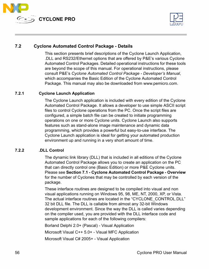
6.3 Cyclone Battery PackManual control of stand-alone mode is also useful for performing field updates. In this situation, there is often no access to a PC or power outlet. However, the Cyclone may be powered by using a Cyclone PowerPack, which is a lightweight and compact lithium ion battery (available separately).
Figure 6-7: Cyclone with Cyclone PowerPack
The combination of the Cyclone programmer and the battery pack creates a fully operational field programming setup that is lightweight, compact, and extremely portable. All that is required for a field update is to connect the battery-powered, pre-programmed Cyclone to the target and initiate programming.
Cyclone PRO User Manual 55
CYCLONE PRO
7 STAND-ALONE PROGRAMMER AUTOMATED CONTROLUsers who wish to automate control of one or more Cyclone units have several options available. This chapter presents a brief overview of those options along with some additional information about each.
7.1 Cyclone Automated Control Package - OverviewEvery Cyclone includes the Basic Edition of P&E’s Cyclone Automated Control Package. P&E also offers advanced versions of the control package which may be purchased separately.
7.1.1 Basic EditionThe Basic Edition, included with the Cyclone PRO, gives users two options for automating control of the Cyclone.
1. Cyclone Launch ApplicationThe Cyclone Launch application allows control of one or more P&E Cyclone units through the usage of simple batch and script files.
2. Dynamic Link Library (.DLL)The .DLL in the Basic Edition allows custom software applications to control one Cyclone unit.
Users wishing to use a .DLL to control more than one Cyclone or who would prefer to use RS232/Ethernet protocols (e.g., in a non-Windows environment) may purchase the appropriate advanced version of the Cyclone Automated Control Package.
7.1.2 Professional EditionThe Professional Edition is available separately. It contains a dynamic link library (DLL) which allows custom software applications to control up to three Cyclone units.
7.1.3 Enterprise EditionThe Enterprise Edition is available separately. It contains a dynamic link library (DLL) and the ability to use custom software, RS232 and Ethernet communication protocols to control an unlimited number of Cyclones.More details about what is included with each edition of the Cyclone Automated Control Package may be found at www.pemicro.com.
56 Cyclone PRO User Manual
CYCLONE PRO
7.2 Cyclone Automated Control Package - DetailsThis section presents brief descriptions of the Cyclone Launch Application, .DLL and RS232/Ethernet options that are offered by P&E’s various Cyclone Automated Control Packages. Detailed operational instructions for these tools are beyond the scope of this manual. For operational instructions, please consult P&E’s Cyclone Automated Control Package - Developer’s Manual, which accompanies the Basic Edition of the Cyclone Automated Control Package. This manual may also be downloaded from www.pemicro.com.
7.2.1 Cyclone Launch ApplicationThe Cyclone Launch application is included with every edition of the Cyclone Automated Control Package. It allows a developer to use simple ASCII script files to control Cyclone operations from the PC. Once the script files are configured, a simple batch file can be created to initiate programming operations on one or more Cyclone units. Cyclone Launch also supports features such as stand-alone image maintenance and dynamic data programming, which provides a powerful but easy-to-use interface. The Cyclone Launch application is ideal for getting your automated production environment up and running in a very short amount of time.
7.2.2 .DLL ControlThe dynamic link library (DLL) that is included in all editions of the Cyclone Automated Control Package allows you to create an application on the PC that can directly control one (Basic Edition) or more P&E Cyclone units. Please see Section 7.1 - Cyclone Automated Control Package - Overview for the number of Cyclones that may be controlled by each version of the package. These interface routines are designed to be compiled into visual and non visual applications running on Windows 95, 98, ME, NT, 2000, XP, or Vista. The actual interface routines are located in the “CYCLONE_CONTROL.DLL” 32 bit DLL file. The DLL is callable from almost any 32-bit Windows development environment. Since the way the DLL is called varies depending on the compiler used, you are provided with the DLL interface code and sample applications for each of the following compilers:Borland Delphi 2.0+ (Pascal) - Visual ApplicationMicrosoft Visual C++ 5.0+ - Visual MFC ApplicationMicrosoft Visual C# 2005+ - Visual Application
Cyclone PRO User Manual 57
CYCLONE PRO
These sample applications come with project and workspaces defined for ease of use. Simply open the project/workspace in your compiler and you should be able to build the sample application without any modifications. The sample applications come pre-compiled with ICONS, so you can run them before jumping into the code.
7.2.3 RS232 / Ethernet Communication ProtocolsThe RS232 and Ethernet Communication protocols included with the Enterprise Edition of the Cyclone Automated Control Package allow a developer to manually send individual command packets to control each Cyclone unit. This is ideal for setups that do not have access to a PC or production environments that do not run Windows-based computers.
58 Cyclone PRO User Manual
CYCLONE PRO
8 PC-HOSTED DEBUG/PROGRAMMING SOFTWAREFree or low-cost software options for interactively programming and debugging HC08, HCS08, RS08, HC(S)12(X), or ColdFire V1 MCUs using a PC are available from P&E Microcomputer Systems (www.pemicro.com) and Freescale (www.freescale.com).
Note: The user should make sure they have the most recent version of these software kits. The latest updates can be downloaded from the web pages listed in Section 8.1.1 - Latest Updates - P&E Software and Section 8.2.1 - Freescale CodeWarrior.
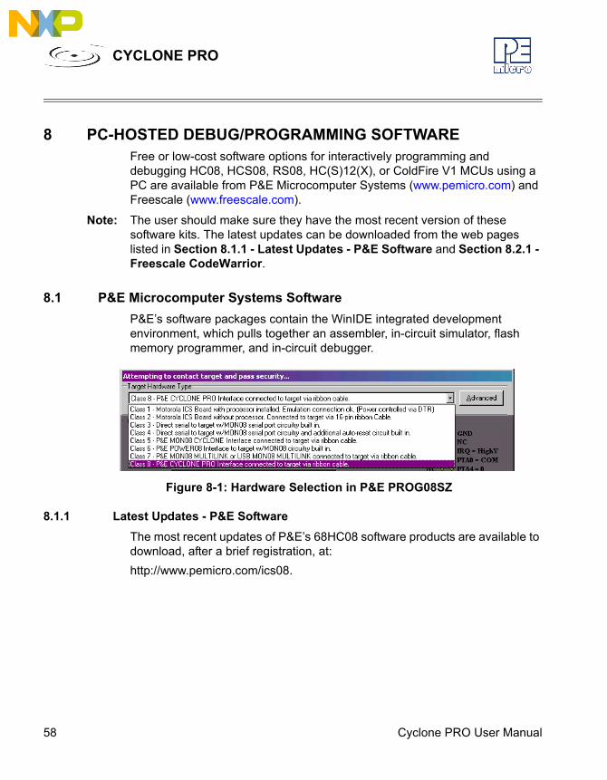
8.1 P&E Microcomputer Systems SoftwareP&E’s software packages contain the WinIDE integrated development environment, which pulls together an assembler, in-circuit simulator, flash memory programmer, and in-circuit debugger.
Figure 8-1: Hardware Selection in P&E PROG08SZ
8.1.1 Latest Updates - P&E SoftwareThe most recent updates of P&E’s 68HC08 software products are available to download, after a brief registration, at:http://www.pemicro.com/ics08.
Cyclone PRO User Manual 59
CYCLONE PRO
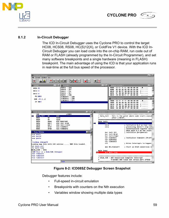
8.1.2 In-Circuit DebuggerThe ICD In-Circuit Debugger uses the Cyclone PRO to control the target HC08, HCS08, RS08, HC(S)12(X), or ColdFire V1 device. With the ICD In-Circuit Debugger you can load code into the on-chip RAM, run code out of RAM or FLASH (already programmed by the In-Circuit Programmer), and set many software breakpoints and a single hardware (meaning in FLASH) breakpoint. The main advantage of using the ICD is that your application runs in real-time at the full bus speed of the processor.
Figure 8-2: ICD08SZ Debugger Screen Snapshot
Debugger features include:• Full-speed in-circuit emulation
• Breakpoints with counters on the Nth execution
• Variables window showing multiple data types
60 Cyclone PRO User Manual
CYCLONE PRO
• Real-time execution as well as multiple tracing modes
• Startup and Macro files for automating the debug process
• Context-sensitive help for all commands
• Support for symbolic register files
• Full source-level debugging
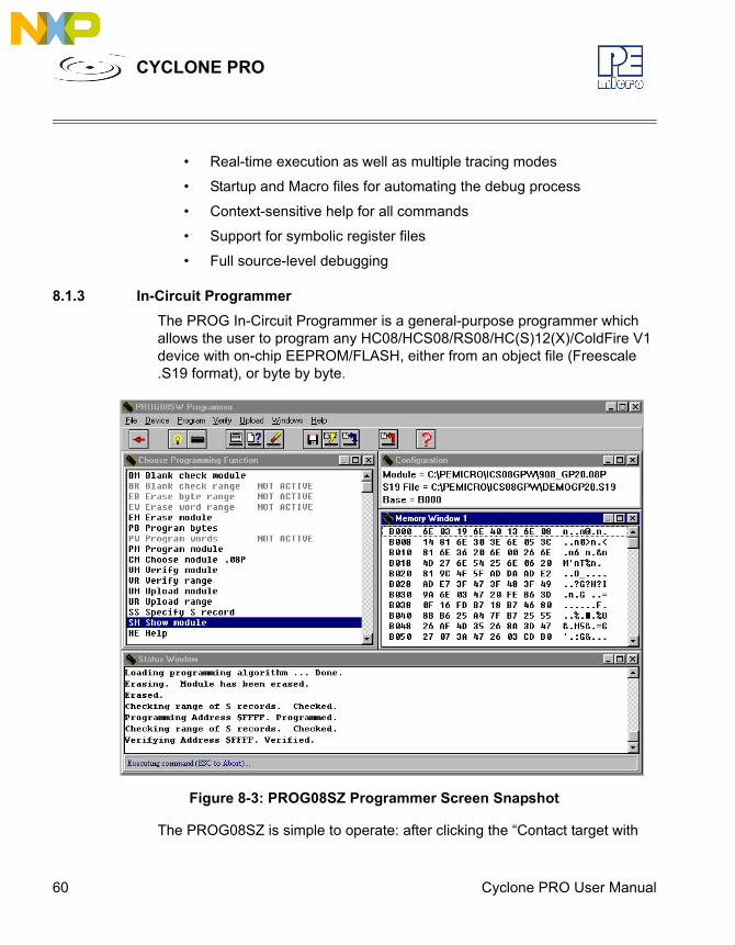
8.1.3 In-Circuit ProgrammerThe PROG In-Circuit Programmer is a general-purpose programmer which allows the user to program any HC08/HCS08/RS08/HC(S)12(X)/ColdFire V1 device with on-chip EEPROM/FLASH, either from an object file (Freescale .S19 format), or byte by byte.
Figure 8-3: PROG08SZ Programmer Screen Snapshot
The PROG08SZ is simple to operate: after clicking the “Contact target with
Cyclone PRO User Manual 61
CYCLONE PRO
these settings” button, if the programmer successfully contacts the target it will ask you for the algorithm you wish to use during programming. Select the proper algorithm for the device you are attempting to program. Then simply select the s-record object you wish to program using the “SS” command. Now the setup of the PROG08SZ is complete and you are ready for operations on the target EEPROM/FLASH. You may choose “EM – Erase Module” to erase the target EEPROM/FLASH. Then use “BM – Blank Check Module” to see if the target EEPROM/FLASH is indeed erased. After that, you may choose “PM – Program Module” to program the S-record object into the target. Finally, you may use “VC – Verify CRC Checksum” to verify that the contents are properly programmed in the target memory.
8.1.4 Command Line ProgrammerCPROG is a command line programmer that allows quick turn-around time for programming target MCUs. The user may create a script file to instruct the software to execute specific commands in sequence. Please refer to CPROG documentation for more information.
8.2 Freescale SoftwareThe special edition of Freescale’s CodeWarrior studio offers absolute assembly and provides debugging capabilities based on P&E’s programming and debug technologies.
8.2.1 Freescale CodeWarriorA programming or debug session with the project-based CodeWarrior IDE may be launched by double-clicking on the project name (format is projectname.mcp) from your file storage. Starting a new project is a little more challenging, but the tutorials, FAQs, and Quick Start Guides are easy to follow and have you building a new project, using pre-built templates, in a short time.The following example illustrates how to program and debug an M68HC908 MCU from within the CodeWarrior IDE.Here are the main steps in programming the FLASH with CodeWarrior and starting a debug session.
1. a. Launch the CodeWarrior CW08 software and create a new project, orb. Double-click on your project file (projectname.mcp)
62 Cyclone PRO User Manual
CYCLONE PRO
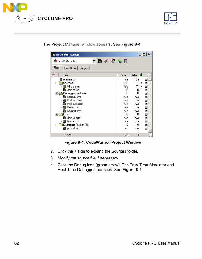
The Project Manager window appears. See Figure 8-4.
Figure 8-4: CodeWarrior Project Window
2. Click the + sign to expand the Sources folder.
3. Modify the source file if necessary.
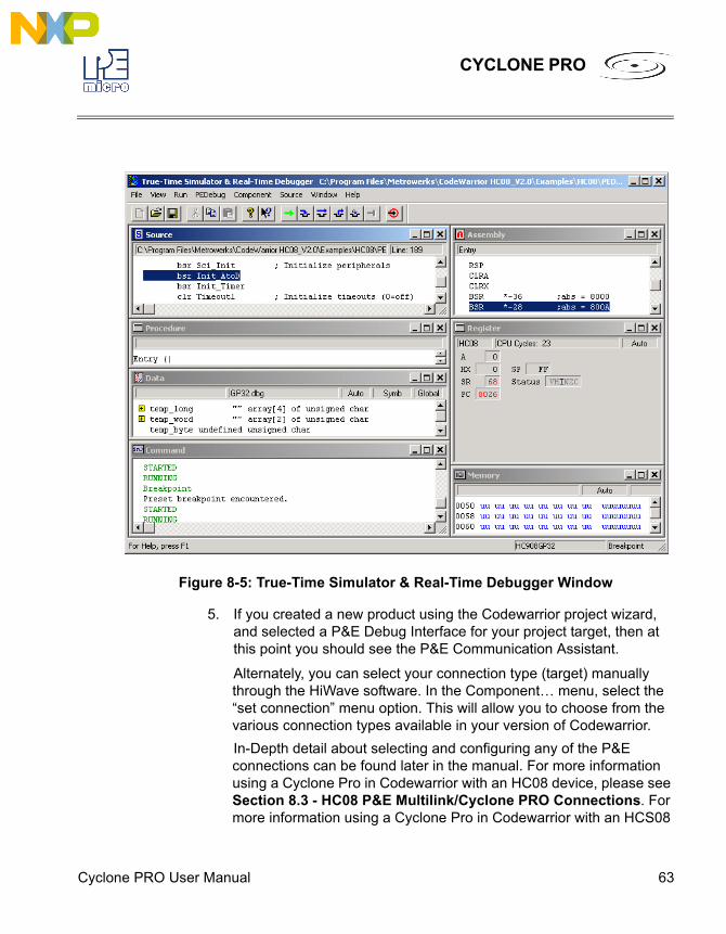
4. Click the Debug icon (green arrow). The True-Time Simulator and Real-Time Debugger launches. See Figure 8-5.
Cyclone PRO User Manual 63
CYCLONE PRO
Figure 8-5: True-Time Simulator & Real-Time Debugger Window
5. If you created a new product using the Codewarrior project wizard, and selected a P&E Debug Interface for your project target, then at this point you should see the P&E Communication Assistant.
Alternately, you can select your connection type (target) manually through the HiWave software. In the Component… menu, select the “set connection” menu option. This will allow you to choose from the various connection types available in your version of Codewarrior.In-Depth detail about selecting and configuring any of the P&E connections can be found later in the manual. For more information using a Cyclone Pro in Codewarrior with an HC08 device, please see Section 8.3 - HC08 P&E Multilink/Cyclone PRO Connections. For more information using a Cyclone Pro in Codewarrior with an HCS08
64 Cyclone PRO User Manual
CYCLONE PRO
device, please see Section 8.4 - HCS08 P&E Multilink/Cyclone PRO Connectionssection 7.4. For more information using a Cyclone Pro in Codewarrior with an HC(S)12 device, please see the Codewarrior User’s manual.
6. After you have configured the Cyclone Pro properly, click the “Contact Target with These Setting” button.
The “Attempting to contact target and pass security” window appears.7. Select the appropriate class in Target Hardware Type (Class VII for
MON08 MULTILINK and Class VIII for Cyclone PRO).
8. Click Contact target with these settings…
9. Follow the Power Cycle dialog instructions.
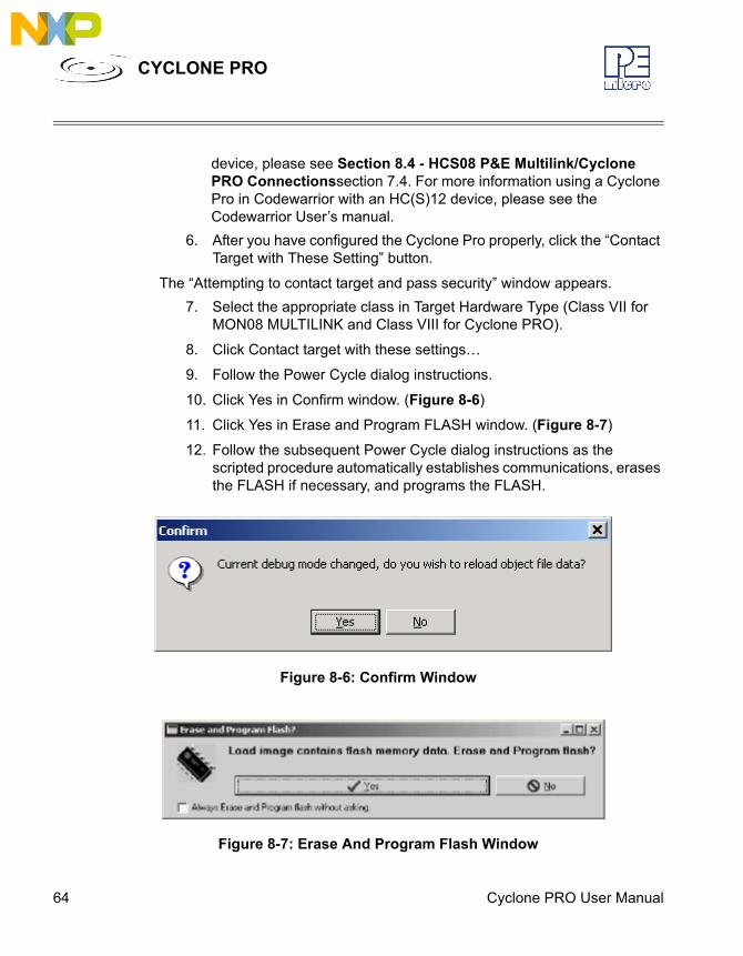
10. Click Yes in Confirm window. (Figure 8-6)
11. Click Yes in Erase and Program FLASH window. (Figure 8-7)
12. Follow the subsequent Power Cycle dialog instructions as the scripted procedure automatically establishes communications, erases the FLASH if necessary, and programs the FLASH.
Figure 8-6: Confirm Window
Figure 8-7: Erase And Program Flash Window
Cyclone PRO User Manual 65
CYCLONE PRO
At this point, the FLASH memory is programmed and ready for debug. The True-Time Simulator & Real-Time Debugger integrates the debugger tools from P&E Microcomputer Systems in this example. The windows look slightly different between the ICD and True-Time tools but the same basic debugger (ICD) drives both.
8.3 HC08 P&E Multilink/Cyclone PRO Connections
8.3.1 IntroductionThe HC08 P&E Multilink/Cyclone PRO Connection setting permits a connection to Class 5, 7 or 8 devices. Please see the descriptions below for a definition of each interface class. HC08 P&E Multilink/Cyclone Pro Connection Interface mode allows the user to debug code, as the firmware is fully resident in the FLASH of the microprocessor. The operation of all modules fully reflects the actual operation of the on-board resources.
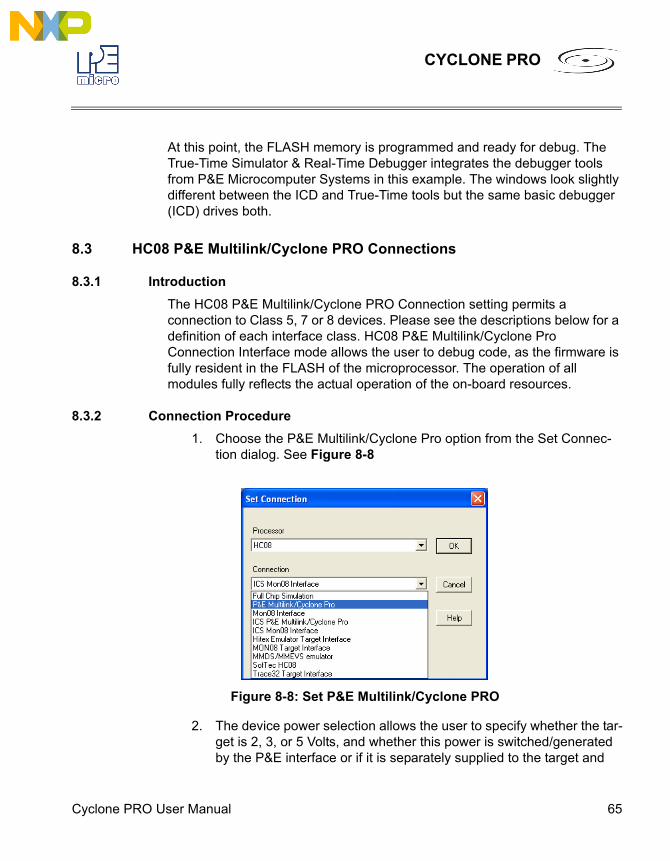
8.3.2 Connection Procedure1. Choose the P&E Multilink/Cyclone Pro option from the Set Connec-
tion dialog. See Figure 8-8.
Figure 8-8: Set P&E Multilink/Cyclone PRO
2. The device power selection allows the user to specify whether the tar-get is 2, 3, or 5 Volts, and whether this power is switched/generated by the P&E interface or if it is separately supplied to the target and
66 Cyclone PRO User Manual
CYCLONE PRO
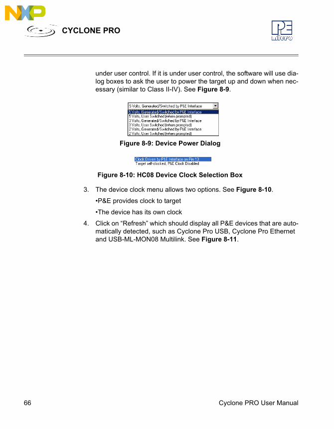
under user control. If it is under user control, the software will use dia-log boxes to ask the user to power the target up and down when nec-essary (similar to Class II-IV). See Figure 8-9.
Figure 8-9: Device Power Dialog
Figure 8-10: HC08 Device Clock Selection Box
3. The device clock menu allows two options. See Figure 8-10.
•P&E provides clock to target
•The device has its own clock
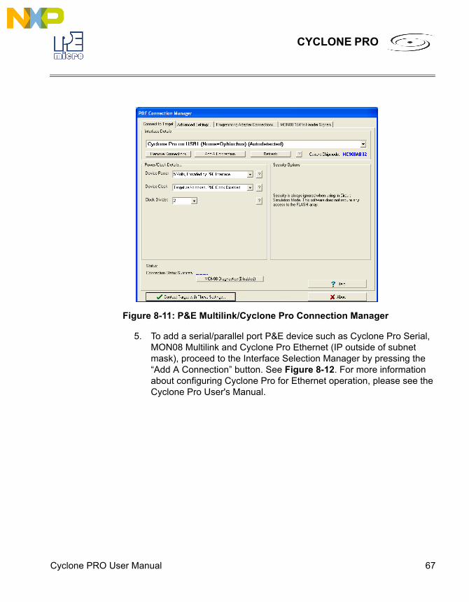
4. Click on “Refresh” which should display all P&E devices that are auto-matically detected, such as Cyclone Pro USB, Cyclone Pro Ethernet and USB-ML-MON08 Multilink. See Figure 8-11.
Cyclone PRO User Manual 67
CYCLONE PRO
Figure 8-11: P&E Multilink/Cyclone Pro Connection Manager
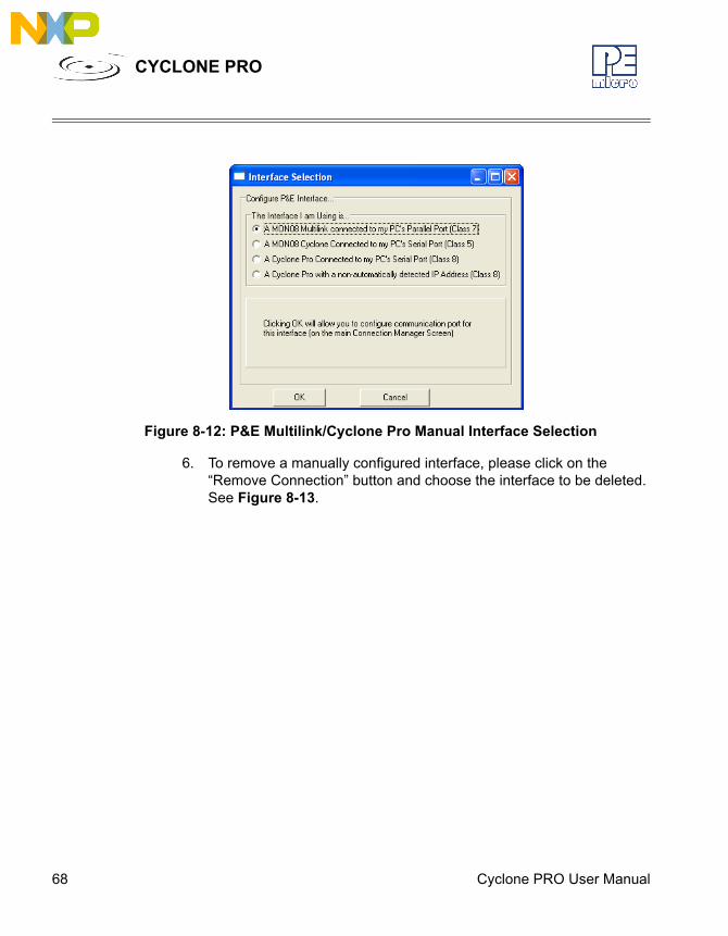
5. To add a serial/parallel port P&E device such as Cyclone Pro Serial, MON08 Multilink and Cyclone Pro Ethernet (IP outside of subnet mask), proceed to the Interface Selection Manager by pressing the “Add A Connection” button. See Figure 8-12. For more information about configuring Cyclone Pro for Ethernet operation, please see the Cyclone Pro User's Manual.
68 Cyclone PRO User Manual
CYCLONE PRO
Figure 8-12: P&E Multilink/Cyclone Pro Manual Interface Selection
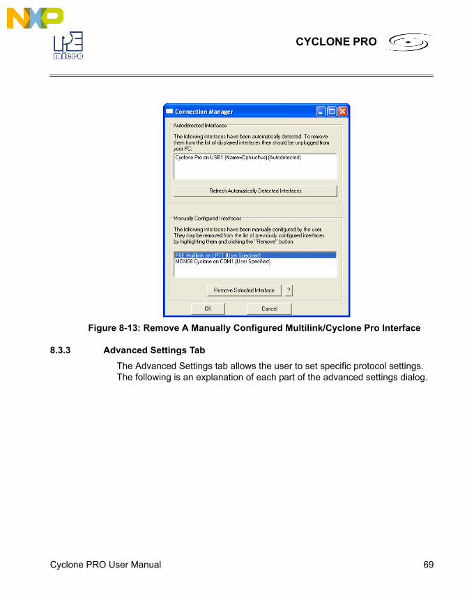
6. To remove a manually configured interface, please click on the “Remove Connection” button and choose the interface to be deleted. See Figure 8-13.
Cyclone PRO User Manual 69
CYCLONE PRO
Figure 8-13: Remove A Manually Configured Multilink/Cyclone Pro Interface
8.3.3 Advanced Settings TabThe Advanced Settings tab allows the user to set specific protocol settings. The following is an explanation of each part of the advanced settings dialog.
70 Cyclone PRO User Manual
CYCLONE PRO
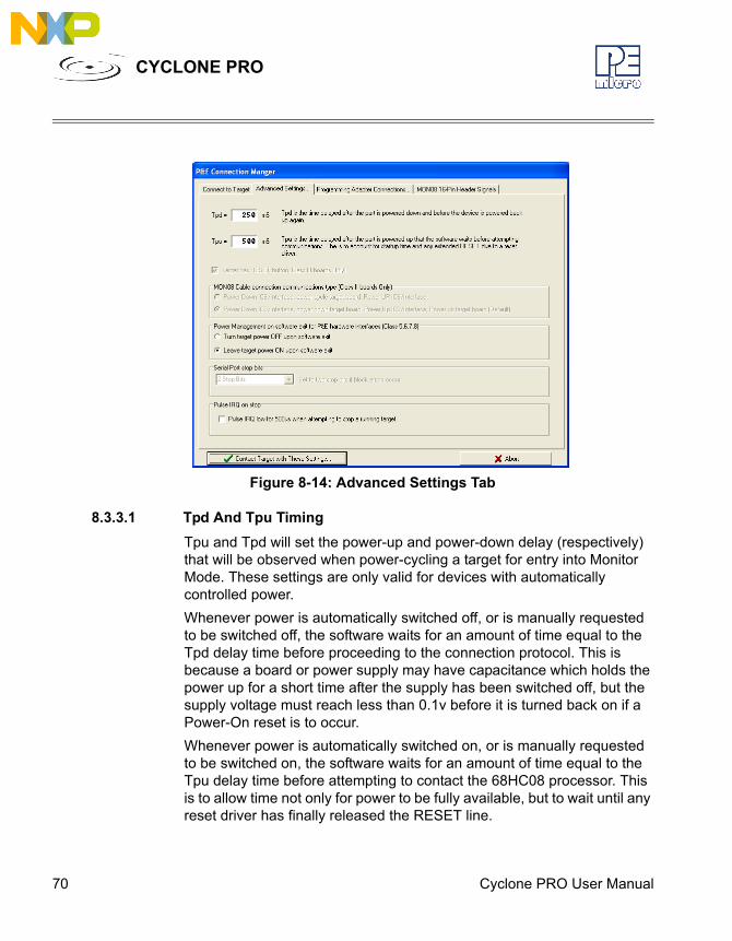
Figure 8-14: Advanced Settings Tab
8.3.3.1 Tpd And Tpu TimingTpu and Tpd will set the power-up and power-down delay (respectively) that will be observed when power-cycling a target for entry into Monitor Mode. These settings are only valid for devices with automatically controlled power.Whenever power is automatically switched off, or is manually requested to be switched off, the software waits for an amount of time equal to the Tpd delay time before proceeding to the connection protocol. This is because a board or power supply may have capacitance which holds the power up for a short time after the supply has been switched off, but the supply voltage must reach less than 0.1v before it is turned back on if a Power-On reset is to occur.Whenever power is automatically switched on, or is manually requested to be switched on, the software waits for an amount of time equal to the Tpu delay time before attempting to contact the 68HC08 processor. This is to allow time not only for power to be fully available, but to wait until any reset driver has finally released the RESET line.
Cyclone PRO User Manual 71
CYCLONE PRO
8.3.3.2 Target Has RESET Button (Class III Boards Only)The software occasionally needs to get control of the target. On systems which are Class III boards with the monitor mode circuitry built-in (including RS-232 driver), there is no means to reset the target to gain control. If the board has a reset button, the software can use this to gain control of the target system. If this option is checked, the software will prompt the user to push the target reset button when a reset of the target system is desired. If the option is unchecked, the software will ask the user to power cycle the target system to achieve a reset.
8.3.3.3 MON08 Cable Connection Communications Type (Class II Boards Only)This selection box is valid only for Class II hardware configurations using the MON08 cable. It allows the user to specify the sequence that the software uses to power up the ICS system. When the software tries to create a power-on reset condition, two events must occur:1. Power of the target MCU must go below 0.1v. This means that the
processor can not be receiving power from its power pins, nor can it have a significant voltage being driven on port pins or the IRQ line, as these will drive the MCU power back through these pins. It is crucial, therefore, to have the ICS and the Target both powered down at some point in time.
2. The processor MON08 configuration pins, including IRQ, must be properly driven when the target processor resets to drive it into moni-tor mode. If these pins are not set up properly before the processor powers up, the processor may start up in user mode.
Power Down ICS, Ask the user to power down their board, Power Up ICS, Ask the user to power up their boardThis is the default option and should work for most, if not all, ICS08/Target Board solutions. Refer to the manual addendum under startup for the settings for a specific ICS board. It requires the user go through two dialog stages, and requires more time than simply cycling the power.1. Software automatically powers down the ICS.
2. Software asks the user to power down the board as follows:
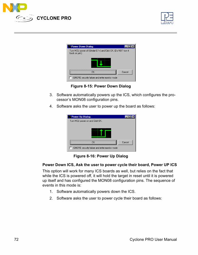
72 Cyclone PRO User Manual
CYCLONE PRO
Figure 8-15: Power Down Dialog
3. Software automatically powers up the ICS, which configures the pro-cessor’s MON08 configuration pins.
4. Software asks the user to power up the board as follows:
Figure 8-16: Power Up Dialog
Power Down ICS, Ask the user to power cycle their board, Power UP ICSThis option will work for many ICS boards as well, but relies on the fact that while the ICS is powered off, it will hold the target in reset until it is powered up itself and has configured the MON08 configuration pins. The sequence of events in this mode is:
1. Software automatically powers down the ICS.
2. Software asks the user to power cycle their board as follows:
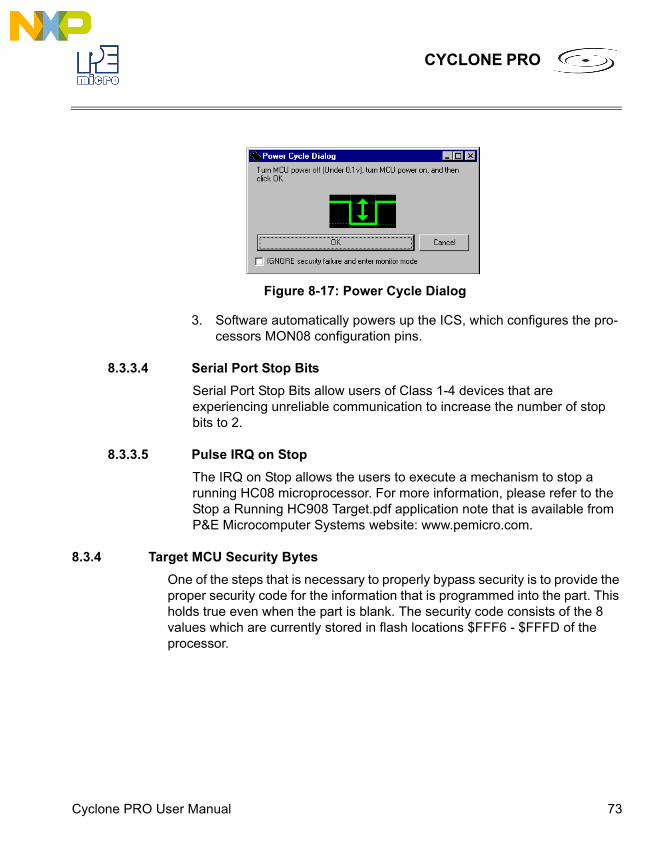
Cyclone PRO User Manual 73
CYCLONE PRO
Figure 8-17: Power Cycle Dialog
3. Software automatically powers up the ICS, which configures the pro-cessors MON08 configuration pins.
8.3.3.4 Serial Port Stop BitsSerial Port Stop Bits allow users of Class 1-4 devices that are experiencing unreliable communication to increase the number of stop bits to 2.
8.3.3.5 Pulse IRQ on StopThe IRQ on Stop allows the users to execute a mechanism to stop a running HC08 microprocessor. For more information, please refer to the Stop a Running HC908 Target.pdf application note that is available from P&E Microcomputer Systems website: www.pemicro.com.
8.3.4 Target MCU Security BytesOne of the steps that is necessary to properly bypass security is to provide the proper security code for the information that is programmed into the part. This holds true even when the part is blank. The security code consists of the 8 values which are currently stored in flash locations $FFF6 - $FFFD of the processor.
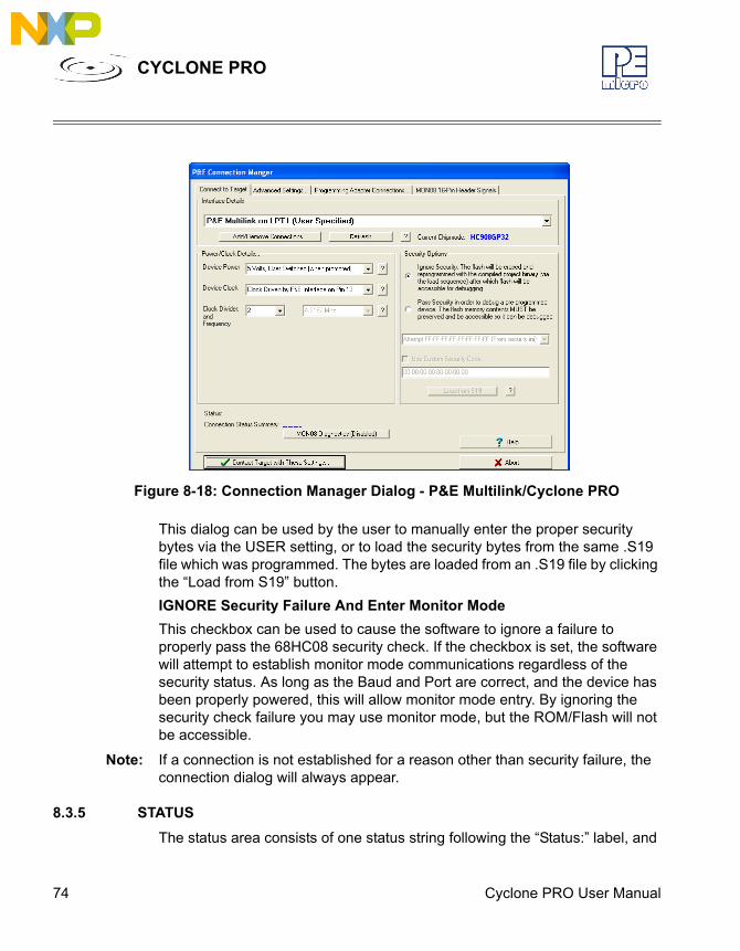
74 Cyclone PRO User Manual
CYCLONE PRO
Figure 8-18: Connection Manager Dialog - P&E Multilink/Cyclone PRO
This dialog can be used by the user to manually enter the proper security bytes via the USER setting, or to load the security bytes from the same .S19 file which was programmed. The bytes are loaded from an .S19 file by clicking the “Load from S19” button.IGNORE Security Failure And Enter Monitor ModeThis checkbox can be used to cause the software to ignore a failure to properly pass the 68HC08 security check. If the checkbox is set, the software will attempt to establish monitor mode communications regardless of the security status. As long as the Baud and Port are correct, and the device has been properly powered, this will allow monitor mode entry. By ignoring the security check failure you may use monitor mode, but the ROM/Flash will not be accessible.
Note: If a connection is not established for a reason other than security failure, the connection dialog will always appear.
8.3.5 STATUSThe status area consists of one status string following the “Status:” label, and
Cyclone PRO User Manual 75
CYCLONE PRO
seven items which list the state of the last attempt to connect to a target and pass security. The description for these items is as follows:0 – ICS Hardware loopback detected: Every ICS or board which supports MON08 has a serial loopback in hardware which, by connecting the transmit and receive lines, automatically echoes characters from the PC. A valid character transmitted from the PC should be echoed once by the loopback circuitry on the board and once by the monitor of the target processor itself. This status indicates whether or not the first echoed character from the hardware loopback was received when one of the security bytes was transmitted. If the status is ‘N’, which indicates that the character was not received, it is most likely due to one of the following reasons:
1. Wrong Com Port specified.
2. The baud rate specified was incorrect (probably too low).
3. The ICS/Target is not connected.
4. No Power to the ICS.
If this status bit responded with an ‘N’, you must correct this before analyzing the reset of the status bits.1 – Device echoed some security bytes: The monitor resident in a 68HC08 device automatically echoes every incoming character when it is in monitor mode. A valid character transmitted from the PC should be echoed once by the loopback circuitry on the board and once by the monitor of the target processor itself. This status indicates whether or not the second echoed character from the monitor response was received when one of the security bytes was transmitted. If the status is ‘N’, which indicates that the character was not received, or not received properly, it is most likely due to one of the following reasons:
1. The baud rate specified was incorrect.
2. The part did not start the monitor mode security check on reset. Sig-nals to force monitor mode may be incorrect.
3. No Power to the ICS.
If this status bit responded with an ‘N’, you must correct this before analyzing the reset of the status bits.2 – Device echoed all security bytes:
76 Cyclone PRO User Manual
CYCLONE PRO
In order to pass security, the software must send 8 security bytes to the processor. The processor should echo each of these eight bytes twice. If all 8 bytes did not get the proper two-byte echo, this flag will be ‘N’. Reasons for this include:
1. The part did not start the monitor mode security check on reset. Sig-nals to force monitor mode may be incorrect.
2. The baud rate specified was incorrect.
3. The processor was not reset properly. Check the “Target Hardware Type” and if you are connecting to a class II board, check the “MON08 cable communication connections type” in the “advanced settings” dialog.
3 – Device signaled monitor mode with a break: Once the processor has properly received the 8 bytes from the PC software to complete its security check, it should transmit a break character to the PC signaling entry into monitor mode. This break should be sent regardless of whether the security check was successfully passed. If a break was not received from the processor, this flag will be ‘N’. Reasons for this include:
1. The baud rate specified was incorrect.
2. The processor was not reset properly. Check the “Target Hardware Type”. If you are connecting to a class II board, check the “MON08 cable communication connections type” in the “advanced settings” dialog.
4 – Device entered monitor mode: Once the software has received, or failed to receive, a break from the processor, it attempts to communicate with the monitor running on the 68HC08 processor. It tries to read the monitor version number by issuing a monitor mode read. If the processor fails to respond properly to this command, this flag will be ‘N’.5 – Reset was Power-On Reset: If the device properly entered monitor mode (4), the software will read the reset status register (RSR). This read does not affect the security sequence, and occurs purely for diagnostic reasons. The reset status register indicates the conditions under which the processor underwent the last reset. For the software to pass the security check properly, it MUST first cause the processor to undergo a Power-On Reset. The software reads the reset status
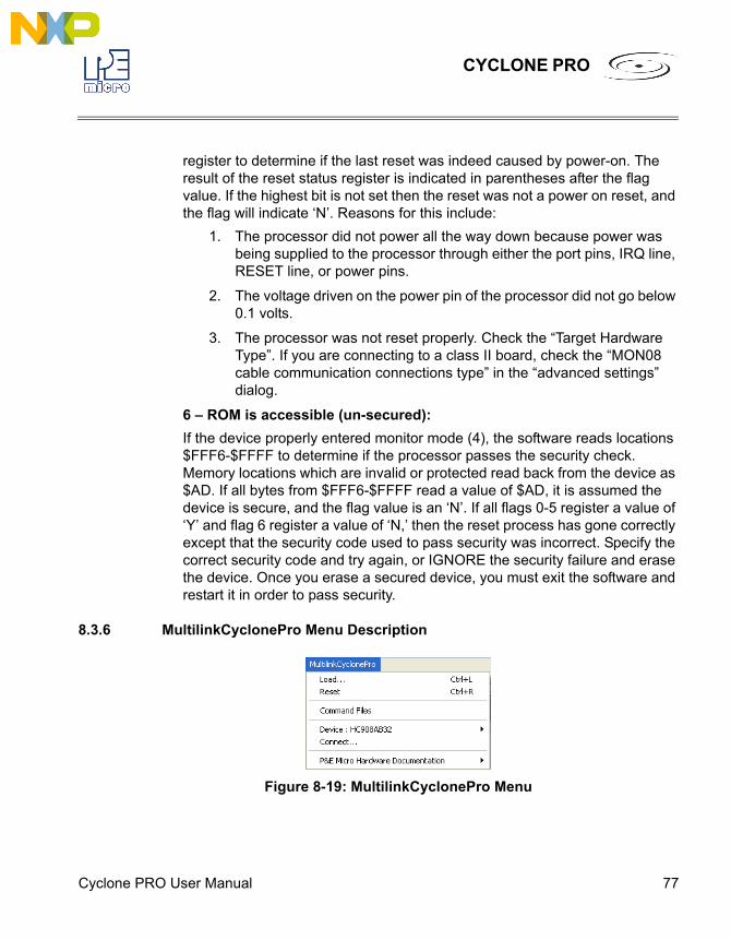
Cyclone PRO User Manual 77
CYCLONE PRO
register to determine if the last reset was indeed caused by power-on. The result of the reset status register is indicated in parentheses after the flag value. If the highest bit is not set then the reset was not a power on reset, and the flag will indicate ‘N’. Reasons for this include:
1. The processor did not power all the way down because power was being supplied to the processor through either the port pins, IRQ line, RESET line, or power pins.
2. The voltage driven on the power pin of the processor did not go below 0.1 volts.
3. The processor was not reset properly. Check the “Target Hardware Type”. If you are connecting to a class II board, check the “MON08 cable communication connections type” in the “advanced settings” dialog.
6 – ROM is accessible (un-secured): If the device properly entered monitor mode (4), the software reads locations $FFF6-$FFFF to determine if the processor passes the security check. Memory locations which are invalid or protected read back from the device as $AD. If all bytes from $FFF6-$FFFF read a value of $AD, it is assumed the device is secure, and the flag value is an ‘N’. If all flags 0-5 register a value of ‘Y’ and flag 6 register a value of ‘N,’ then the reset process has gone correctly except that the security code used to pass security was incorrect. Specify the correct security code and try again, or IGNORE the security failure and erase the device. Once you erase a secured device, you must exit the software and restart it in order to pass security.
8.3.6 MultilinkCyclonePro Menu Description
Figure 8-19: MultilinkCyclonePro Menu
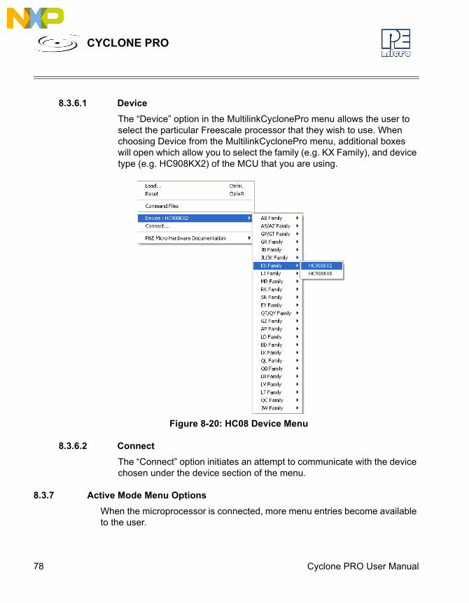
78 Cyclone PRO User Manual
CYCLONE PRO
8.3.6.1 DeviceThe “Device” option in the MultilinkCyclonePro menu allows the user to select the particular Freescale processor that they wish to use. When choosing Device from the MultilinkCyclonePro menu, additional boxes will open which allow you to select the family (e.g. KX Family), and device type (e.g. HC908KX2) of the MCU that you are using.
Figure 8-20: HC08 Device Menu
8.3.6.2 ConnectThe “Connect” option initiates an attempt to communicate with the device chosen under the device section of the menu.
8.3.7 Active Mode Menu OptionsWhen the microprocessor is connected, more menu entries become available to the user.
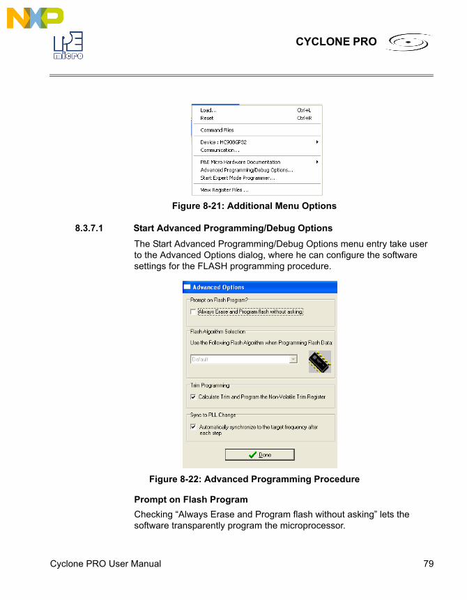
Cyclone PRO User Manual 79
CYCLONE PRO
Figure 8-21: Additional Menu Options
8.3.7.1 Start Advanced Programming/Debug OptionsThe Start Advanced Programming/Debug Options menu entry take user to the Advanced Options dialog, where he can configure the software settings for the FLASH programming procedure.
Figure 8-22: Advanced Programming Procedure
Prompt on Flash ProgramChecking “Always Erase and Program flash without asking” lets the software transparently program the microprocessor.
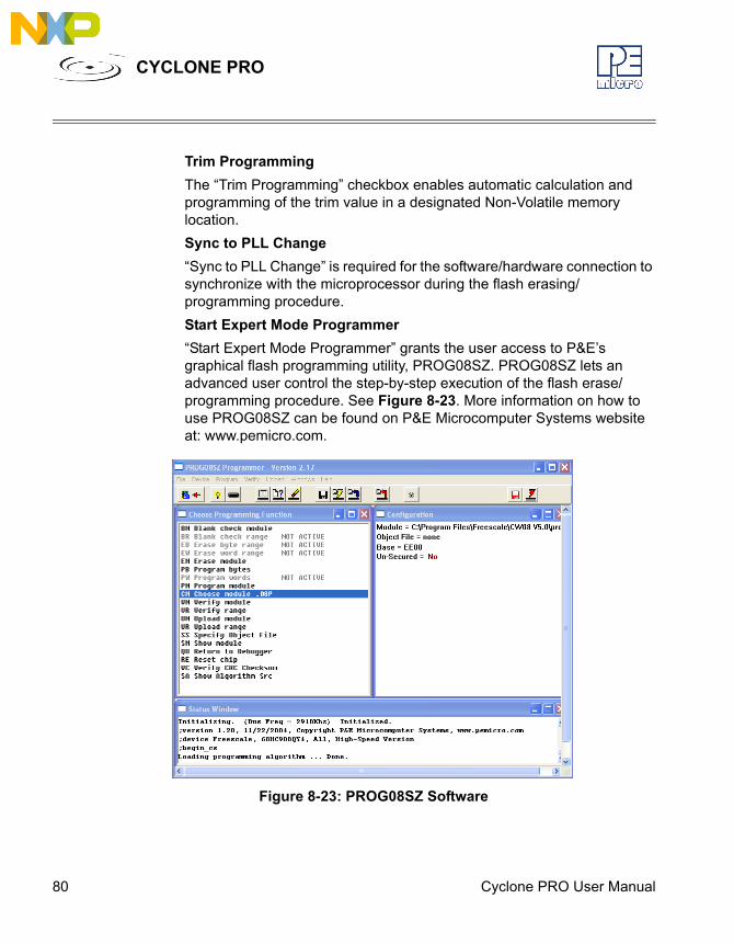
80 Cyclone PRO User Manual
CYCLONE PRO
Trim ProgrammingThe “Trim Programming” checkbox enables automatic calculation and programming of the trim value in a designated Non-Volatile memory location. Sync to PLL Change“Sync to PLL Change” is required for the software/hardware connection to synchronize with the microprocessor during the flash erasing/programming procedure.Start Expert Mode Programmer“Start Expert Mode Programmer” grants the user access to P&E’s graphical flash programming utility, PROG08SZ. PROG08SZ lets an advanced user control the step-by-step execution of the flash erase/programming procedure. See Figure 8-23. More information on how to use PROG08SZ can be found on P&E Microcomputer Systems website at: www.pemicro.com.
Figure 8-23: PROG08SZ Software
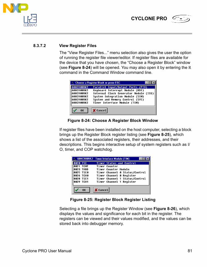
Cyclone PRO User Manual 81
CYCLONE PRO
8.3.7.2 View Register FilesThe “View Register Files...” menu selection also gives the user the option of running the register file viewer/editor. If register files are available for the device that you have chosen, the “Choose a Register Block” window (see Figure 8-24) will be opened. You may also open it by entering the R command in the Command Window command line.
Figure 8-24: Choose A Register Block Window
If register files have been installed on the host computer, selecting a block brings up the Register Block register listing (see Figure 8-25), which shows a list of the associated registers, their addresses, and their descriptions. This begins interactive setup of system registers such as I/O, timer, and COP watchdog.
Figure 8-25: Register Block Register Listing
Selecting a file brings up the Register Window (see Figure 8-26), which displays the values and significance for each bit in the register. The registers can be viewed and their values modified, and the values can be stored back into debugger memory.
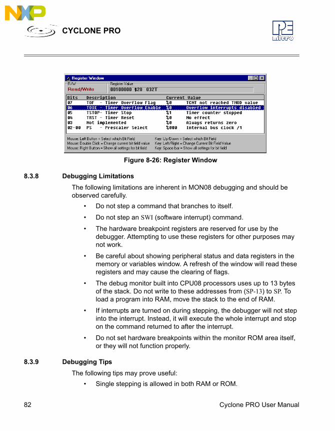
82 Cyclone PRO User Manual
CYCLONE PRO
Figure 8-26: Register Window
8.3.8 Debugging LimitationsThe following limitations are inherent in MON08 debugging and should be observed carefully.
• Do not step a command that branches to itself.
• Do not step an SWI (software interrupt) command.
• The hardware breakpoint registers are reserved for use by the debugger. Attempting to use these registers for other purposes may not work.
• Be careful about showing peripheral status and data registers in the memory or variables window. A refresh of the window will read these registers and may cause the clearing of flags.
• The debug monitor built into CPU08 processors uses up to 13 bytes of the stack. Do not write to these addresses from (SP-13) to SP. To load a program into RAM, move the stack to the end of RAM.
• If interrupts are turned on during stepping, the debugger will not step into the interrupt. Instead, it will execute the whole interrupt and stop on the command returned to after the interrupt.
• Do not set hardware breakpoints within the monitor ROM area itself, or they will not function properly.
8.3.9 Debugging TipsThe following tips may prove useful:
• Single stepping is allowed in both RAM or ROM.

Cyclone PRO User Manual 83
CYCLONE PRO
• The first breakpoint set is always a hardware breakpoint, and any additional breakpoints set are software breakpoints. To make sure that a hardware breakpoint is being set, make sure only one breakpoint is being used.
• Hardware breakpoints will stop execution in ROM or RAM. Software breakpoints will stop execution only in RAM.
• Experiment with the register interpreter. Use the “View Register Files...” option in the MultilinkCyclonePRO menu.
• Executing an SWI instruction while running is functionally equivalent to hitting a breakpoint, except that execution stops at the instruction following the SWI.
• A hardware breakpoint may be used to trap a data read/write to anywhere in the memory map. The debugger stops at the instruction after the one that accesses the data location.
• When the target board is reset by the debugger, power to the microcontroller may be turned off for a short duration. Although much of RAM may look the same, some values may have changed.
8.3.10 Class 5-8 Device Description
8.3.10.1 Class 5P&E’s MON08 Cyclone Device connects to a PC via the serial port. The Cyclone-to-MCU connection occurs via a standard 16-pin MON08 ribbon cable. The MON08 Cyclone Device allows the user to auto-detect the baud rate as well as auto-cycle the power through the MCU system.
8.3.10.2 Class 7P&E MON08 Multilink and USB MON08 Multilink cables connect to the user’s MCU system via a standard 16-pin MON08 ribbon cable. MON08 Multilink and USB MON08 Multilink allow one to auto-detect the baud rate as well as auto-cycle the power through the microprocessor system.
8.3.10.3 Class 8P&E’s Cyclone Pro communicates with the PC through a Serial, Ethernet or USB port. The Cyclone Pro can be used to debug and program the firmware inside of Freescale HC08 microprocessors via a standard 16 pin
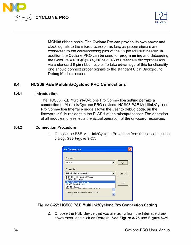
84 Cyclone PRO User Manual
CYCLONE PRO
MON08 ribbon cable. The Cyclone Pro can provide its own power and clock signals to the microprocessor, as long as proper signals are connected to the corresponding pins of the 16 pin MON08 header. In addition the Cyclone PRO can be used for programming and debugging the ColdFire V1/HC(S)12(X)/HCS08/RS08 Freescale microprocessors via a standard 6 pin ribbon cable. To take advantage of this functionality, one should connect proper signals to the standard 6 pin Background Debug Module header.
8.4 HCS08 P&E Multilink/Cyclone PRO Connections
8.4.1 IntroductionThe HCS08 P&E Multilink/Cyclone Pro Connection setting permits a connection to Multilink/Cyclone PRO devices. HCS08 P&E Multilink/Cyclone Pro Connection Interface mode allows the user to debug code, as the firmware is fully resident in the FLASH of the microprocessor. The operation of all modules fully reflects the actual operation of the on-board resources.
8.4.2 Connection Procedure1. Choose the P&E Multilink/Cyclone Pro option from the set connection
dialog: See Figure 8-27.
Figure 8-27: HCS08 P&E Multilink/Cyclone Pro Connection Setting
2. Choose the P&E device that you are using from the Interface drop-down menu and click on Refresh. See Figure 8-28 and Figure 8-29.
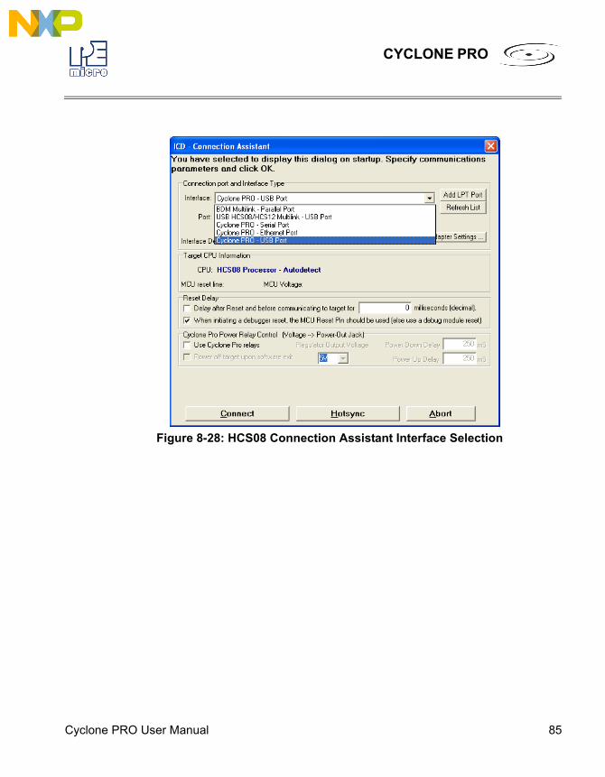
Cyclone PRO User Manual 85
CYCLONE PRO
Figure 8-28: HCS08 Connection Assistant Interface Selection
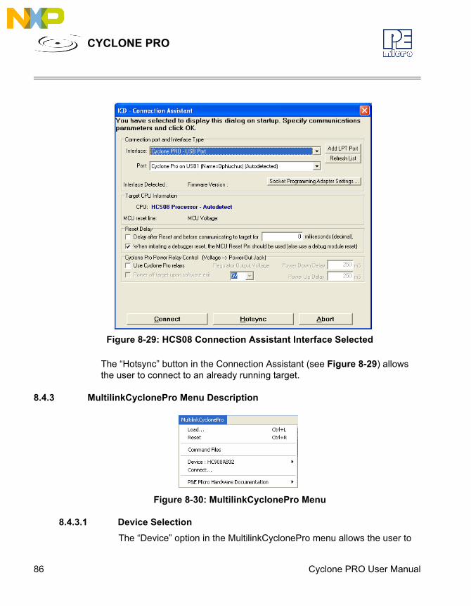
86 Cyclone PRO User Manual
CYCLONE PRO
Figure 8-29: HCS08 Connection Assistant Interface Selected
The “Hotsync” button in the Connection Assistant (see Figure 8-29) allows the user to connect to an already running target.
8.4.3 MultilinkCyclonePro Menu Description
Figure 8-30: MultilinkCyclonePro Menu
8.4.3.1 Device SelectionThe “Device” option in the MultilinkCyclonePro menu allows the user to
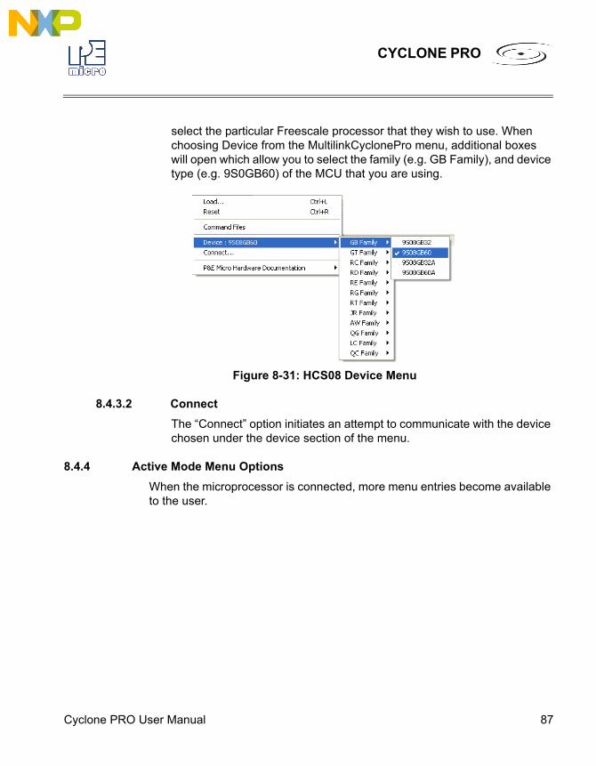
Cyclone PRO User Manual 87
CYCLONE PRO
select the particular Freescale processor that they wish to use. When choosing Device from the MultilinkCyclonePro menu, additional boxes will open which allow you to select the family (e.g. GB Family), and device type (e.g. 9S0GB60) of the MCU that you are using.
Figure 8-31: HCS08 Device Menu
8.4.3.2 ConnectThe “Connect” option initiates an attempt to communicate with the device chosen under the device section of the menu.
8.4.4 Active Mode Menu OptionsWhen the microprocessor is connected, more menu entries become available to the user.
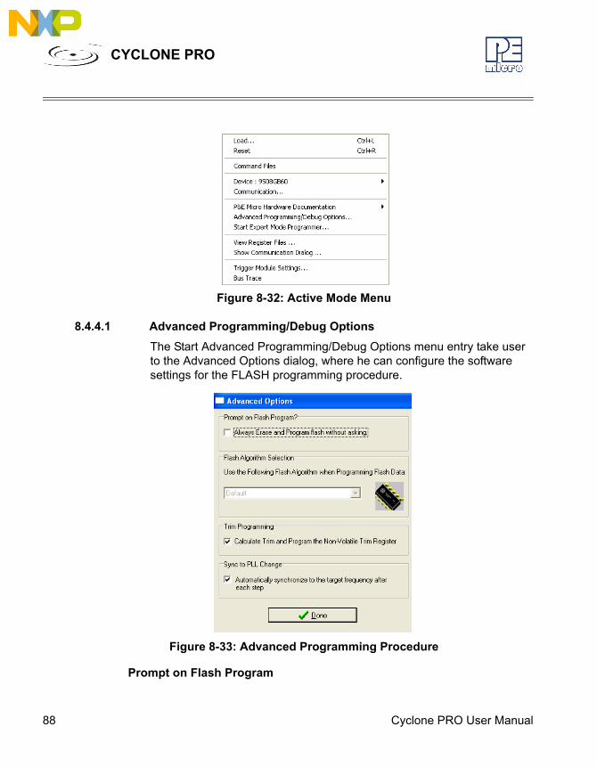
88 Cyclone PRO User Manual
CYCLONE PRO
Figure 8-32: Active Mode Menu
8.4.4.1 Advanced Programming/Debug OptionsThe Start Advanced Programming/Debug Options menu entry take user to the Advanced Options dialog, where he can configure the software settings for the FLASH programming procedure.
Figure 8-33: Advanced Programming Procedure
Prompt on Flash Program
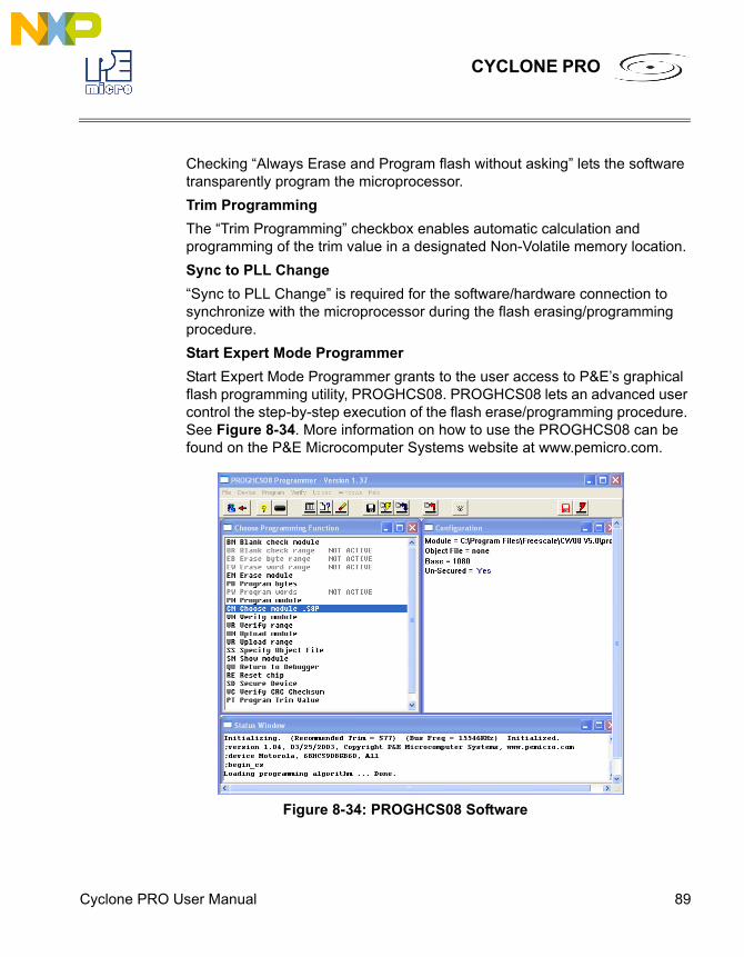
Cyclone PRO User Manual 89
CYCLONE PRO
Checking “Always Erase and Program flash without asking” lets the software transparently program the microprocessor.Trim ProgrammingThe “Trim Programming” checkbox enables automatic calculation and programming of the trim value in a designated Non-Volatile memory location. Sync to PLL Change“Sync to PLL Change” is required for the software/hardware connection to synchronize with the microprocessor during the flash erasing/programming procedure.Start Expert Mode ProgrammerStart Expert Mode Programmer grants to the user access to P&E’s graphical flash programming utility, PROGHCS08. PROGHCS08 lets an advanced user control the step-by-step execution of the flash erase/programming procedure. See Figure 8-34. More information on how to use the PROGHCS08 can be found on the P&E Microcomputer Systems website at www.pemicro.com.
Figure 8-34: PROGHCS08 Software
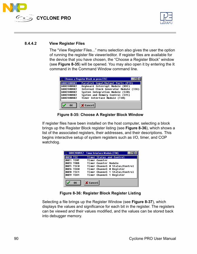
90 Cyclone PRO User Manual
CYCLONE PRO
8.4.4.2 View Register FilesThe “View Register Files...” menu selection also gives the user the option of running the register file viewer/editor. If register files are available for the device that you have chosen, the “Choose a Register Block” window (see Figure 8-35) will be opened. You may also open it by entering the R command in the Command Window command line.
Figure 8-35: Choose A Register Block Window
If register files have been installed on the host computer, selecting a block brings up the Register Block register listing (see Figure 8-36), which shows a list of the associated registers, their addresses, and their descriptions. This begins interactive setup of system registers such as I/O, timer, and COP watchdog.
Figure 8-36: Register Block Register Listing
Selecting a file brings up the Register Window (see Figure 8-37), which displays the values and significance for each bit in the register. The registers can be viewed and their values modified, and the values can be stored back into debugger memory.
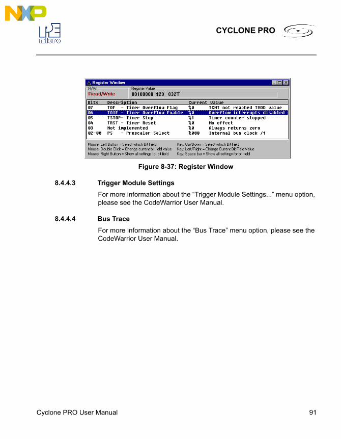
Cyclone PRO User Manual 91
CYCLONE PRO
Figure 8-37: Register Window
8.4.4.3 Trigger Module SettingsFor more information about the “Trigger Module Settings...” menu option, please see the CodeWarrior User Manual.
8.4.4.4 Bus TraceFor more information about the “Bus Trace” menu option, please see the CodeWarrior User Manual.
92 Cyclone PRO User Manual
CYCLONE PRO
9 ETHERNET CONFIGURATIONThis section describes the mechanism used by the Cyclone PRO device to transact data over an Ethernet network. It primarily focuses on the User Datagram Protocol (UDP), which is a popular method for sending data over a network when the speed of a data transaction is of more concern than the guarantee of its delivery. The Cyclone takes advantage of the UDP protocol’s penchant for speed, and adds an extra layer of logic to guarantee the delivery of UDP packets in order to offer a best-of-both-worlds solution.
9.1 Network ArchitecturesBefore delving into the innards of Ethernet message passing, it is prudent to briefly describe the different network architectures in use today, and how they pertain to the operation of the Cyclone. Computers are, of course, connected to one another through intermediary devices in order to form networks. There are several classes of these intermediary devices, but they generally fall into one of the following three groups:
HubsAt the most basic level, computers are connected to one another through a Hub. A Hub is a device with several ports that are used to connect multiple computers together. It is a repeater device – a Hub simply copies the data incoming on one port as data outgoing on the other ports. In this manner, if there are four computers connected through a Hub, and if the first computer is sending data to the second computer, then the third and the fourth computers will also receive an identical copy of that data. Hubs are usually used to set up a small Local Area Network (LAN), which may have on the order of 10 to 20 computers.
Cyclone PRO User Manual 93
CYCLONE PRO
SwitchesThe aforementioned type of process, where the data is simply replicated onto every available port, quickly becomes inefficient for larger sized networks. For this reason, a larger sized LAN employs the usage of Switches instead of Hubs. A Switch is essentially a smart Hub, in that it limits the input and output of data to the two transacting computers.RoutersLarger networks, such as Wide Area Networks (WANs), or the Internet for that matter, use progressively more sophisticated devices to transact data. At the core of these devices is the Router, which functions as a switch between networks.
The Cyclone performs irrespective of the connection mechanism, with one very important caveat: it needs to be set up with the appropriate network parameters for the underlying network architecture.
9.2 Network ParametersA typical network becomes operational not after the physical connections have been established, but after network parameters in the form of IP (Internet Protocol) numbers have been assigned to the individual computers. An IP number is a unique string that consists of four numbers ranging between 0 and 255, separated by dots, e.g., 192.168.1.2. Every computer that is on a network needs to have a unique IP number. The computer uses this IP number to identify itself on the network, and also to address the recipient of its data.Assignation of this IP number is sufficient information to transact data on a simple network connected by a hub. On a more complex network, however, routing information becomes important. The routing information consists of two more IP numbers. The first of these is called the Subnet Mask, and is used to determine whether or not the destination address resides on the same subnet (i.e., doesn’t need to be forwarded to another network). The other IP number is the Gateway Address, which is the address of the computer that handles forwarding and receiving of packets to and from other networks.Before first use, the Cyclone needs to be programmed with a unique IP number, the Subnet Mask IP number, and also the default Gateway’s IP number. This can be done via the USB or the Serial port, and is described in
94 Cyclone PRO User Manual
CYCLONE PRO
greater detail in the “Configuring the Cyclone” section of this manual.
9.3 Internet ProtocolOnce the network has been established, and the IP numbers have been assigned, data can be transacted over a network with one of several protocols. By far the most prevalent protocol is the Transmission Control Protocol (TCP), which runs on top of the Internet Protocol in what is collectively known as the TCP/IP protocol. The TCP/IP protocol was developed by the Department of Defense to connect different computers from different vendors by a “network of networks,” which has become what is known as the Internet today. The primary purpose of the TCP/IP protocol was to prevent a complete network outage in the case of a nuclear attack, by automatically rerouting data traffic through the functioning part of the network. As such, the TCP/IP mechanism guaranteed delivery of data packets by introducing a system of acknowledgements and sequence numbers for the data packets. This mechanism, while good for transacting large amounts of data (such as email or file transfers), is unsuitable in the real-time type environment in which the Cyclone operates. Because the Cyclone needs to transact data as quickly as possible to the target, it takes advantage of TCP/IP’s alternative, the UDP/IP protocol.Unlike TCP/IP, the UDP/IP protocol is a connectionless, single-packet protocol that sends short data packets at the expense of not guaranteeing their delivery. This makes the UDP/IP protocol efficient in real-time applications such as broadcasting video over the Internet, where the occasional loss of a frame of data is not going to hamper the overall viewing experience. Left unmodified, the UDP/IP, with its lack of guarantees for packet delivery, would be unusable in an environment where the delivery of a single byte of data needs to be guaranteed. The Cyclone firmware adds mechanisms to the UDP/IP protocol, without affecting its underlying efficiency, to guarantee delivery of data packets.
9.4 Connecting The Cyclone DeviceThere are two methods for establishing a connection between a Cyclone and a PC with an Ethernet cable. The most basic method is to connect the Cyclone directly to a PC, via a cross-over Ethernet cable. However, the more common method is to place the Cyclone and the PC on the same network
Cyclone PRO User Manual 95
CYCLONE PRO
through a Hub.
9.4.1 Connecting the Cyclone to the PC over a network:The Cyclone was intended for use on a network of multiple computers (and other Cyclones). There are many possible network configurations, and to describe them all is beyond the scope of this document. However, most configurations are a modification of a basic theme, which is that of connecting one or more PCs through a Hub to one or more Cyclones.In order to connect these devices to the Hub, you will need to use the provided straight-through Ethernet cable. The straight-through cable, which is the “standard” Ethernet cable, is used to connect devices of different types together, such as a PC to a Hub, or a Hub to a Cyclone. At this point it once again becomes necessary to program the Cyclone with valid IP numbers, the process for which is described in greater detail in the following section. However, it is important for the Cyclone and the PCs to have matching Subnet and Gateway IP numbers, and for each to have a unique IP number on the network. An example of a setting for above is as follows:
IP Number Gateway IP Subnet MaskPC1 192.168.100.1 192.168.100.3 255.255.255.0PC2 192.168.100.2 192.168.100.3 255.255.255.0CYCLONE 192.168.100.4 192.168.100.3 255.255.255.0Gateway 192.168.100.3 192.168.100.3 255.255.255.0It is important to briefly touch upon the underlying network architecture, which can be a 10Mb (Megabit), 100Mb, 10/100Mb, half-duplex, or a full-duplex connection. The details of the underlying network architecture are beyond the scope of this document, but it is sufficient to note that most modern network cards, as well as the Cyclone device, have the capability to configure themselves for the underlying network through the Auto-negotiation mechanism. Auto-negotiation is performed as soon as a network cable is connected to the device, and it sets the operating parameters of the device to match those of the network.
9.4.2 Connecting Cyclone-to-PC via an Ethernet cableIn order to connect the Cyclone to a PC directly via an Ethernet cable, you need to use what is known as a cross-over cable. A cross-over cable, which is
96 Cyclone PRO User Manual
CYCLONE PRO
not provided by P&E, is normally used to connect two similar devices such as a PC to a PC, or a Hub to a Hub. It is a cable that has its receive and transmit wires crossed over so that the similar devices can effectively communicate with one another. With this configuration, it is still important to assign IP numbers to both the PC and the Cyclone device. Although at first glance it may not seem necessary to assign a Gateway address in this configuration, the Cyclone was designed to operate on a network of more than two computers, and therefore it needs to be programmed with a Gateway address. Assuming the desktop’s IP number to be 192.168.100.1, this is an example of the three IP numbers that would need to be programmed into the Cyclone:
IP Number Gateway IP Subnet MaskPC 192.168.100.1 none 255.255.255.0CYCLONE 192.168.100.2 192.168.100.1 255.255.255.0For more information on programming these IP numbers into the Cyclone device, please see the following section.
9.5 Cyclone IP Setup Via LCD MenuFor instructions on how to configure the Cyclone PRO using the LCD Menu, please see Section 6.2 - Operation Via LCD Menu (Rev. C Only).
9.6 Cyclone IP Setup Utility User Interface (ConfigureIP)Before the Cyclone device transacts data on an Ethernet network, it will need to be configured with the relevant network parameters. The application that provides this capability is the Cyclone IP Setup Utility (ConfigureIP), which can be found as part of the distribution software.This utility is used to configure the Cyclone PRO with network parameters, and also to update the firmware of the Cyclone PRO.
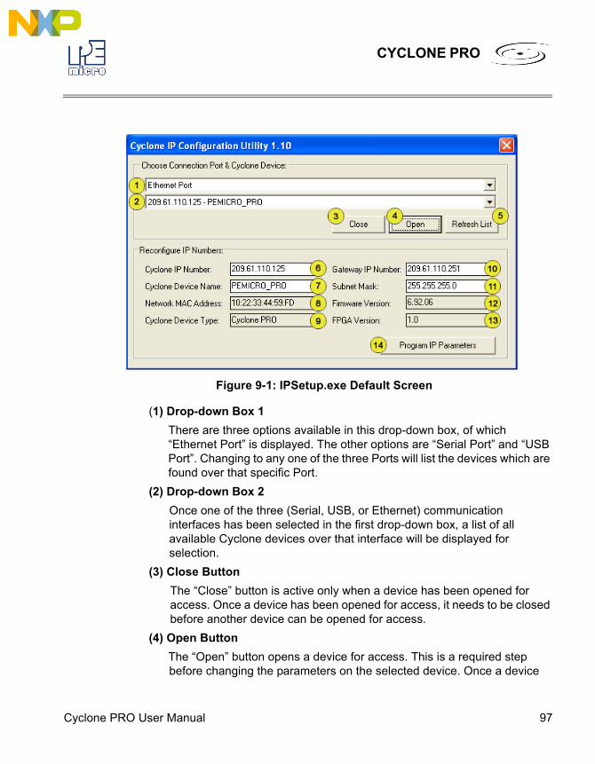
Cyclone PRO User Manual 97
CYCLONE PRO
Figure 9-1: IPSetup.exe Default Screen
(1) Drop-down Box 1There are three options available in this drop-down box, of which “Ethernet Port” is displayed. The other options are “Serial Port” and “USB Port”. Changing to any one of the three Ports will list the devices which are found over that specific Port.
(2) Drop-down Box 2Once one of the three (Serial, USB, or Ethernet) communication interfaces has been selected in the first drop-down box, a list of all available Cyclone devices over that interface will be displayed for selection.
(3) Close ButtonThe “Close” button is active only when a device has been opened for access. Once a device has been opened for access, it needs to be closed before another device can be opened for access.
(4) Open ButtonThe “Open” button opens a device for access. This is a required step before changing the parameters on the selected device. Once a device
98 Cyclone PRO User Manual
CYCLONE PRO
has been selected through the second drop-down box and is opened for access, its information will be displayed at the bottom of the dialog box.
(5) Refresh ListWill refresh the dialog boxes by searching for devices which are currently connected via the Serial or USB interfaces, or are found on the network.
(6) Cyclone IP NumberThis is the IP number which will be associated with the Cyclone PRO. It needs to be a unique IP number which can be accessible on the network.
(7) Cyclone Device NameThis is a label which can be used to identify the Cyclone PRO by name, e.g., “John’s Cyclone” or “Manufacturing Floor.”
(8) MAC AddressThis is the Media Access Control address, the unique number of an Ethernet device on the network. This is programmed by P&E and cannot be modified.
(9) Cyclone Device TypeThis displays the type of Cyclone hardware.
(10) Gateway IP NumberThe IP number of a gateway on the network.
(11) Subnet MaskThe subnet mask of the network.
(12) Firmware VersionA read-only field which returns information pertaining to the build date and firmware version of the Cyclone PRO device.
(13) FPGA VersionA read-only field which returns the hardware version of the FPGA.
(14) Program Cyclone ParametersThis button saves the information as it appears in the "Reconfigure IP Numbers" area onto the Cyclone device.
9.7 Using ConfigureIP.exe To Configure The Cyclone PROBefore the Cyclone PRO is ready to communicate over an Ethernet network,
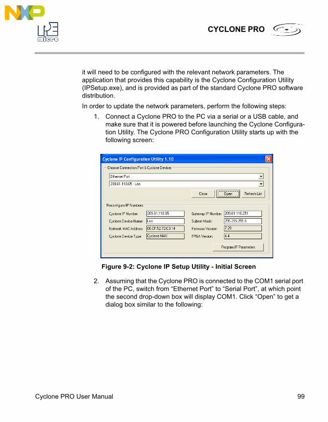
Cyclone PRO User Manual 99
CYCLONE PRO
it will need to be configured with the relevant network parameters. The application that provides this capability is the Cyclone Configuration Utility (IPSetup.exe), and is provided as part of the standard Cyclone PRO software distribution.In order to update the network parameters, perform the following steps:
1. Connect a Cyclone PRO to the PC via a serial or a USB cable, and make sure that it is powered before launching the Cyclone Configura-tion Utility. The Cyclone PRO Configuration Utility starts up with the following screen:
Figure 9-2: Cyclone IP Setup Utility - Initial Screen
2. Assuming that the Cyclone PRO is connected to the COM1 serial port of the PC, switch from “Ethernet Port” to “Serial Port”, at which point the second drop-down box will display COM1. Click “Open” to get a dialog box similar to the following:
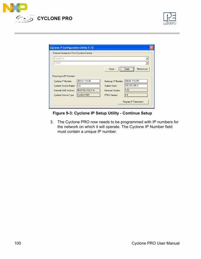
100 Cyclone PRO User Manual
CYCLONE PRO
Figure 9-3: Cyclone IP Setup Utility - Continue Setup
3. The Cyclone PRO now needs to be programmed with IP numbers for the network on which it will operate. The Cyclone IP Number field must contain a unique IP number.
Cyclone PRO User Manual 101
CYCLONE PRO
10 SERIAL PORT CONFIGURATIONStandard serial cables may be used for serial port Cyclone PRO configuration.
102 Cyclone PRO User Manual
CYCLONE PRO
11 USB PORT CONFIGURATIONStandard USB cables may be used for USB port Cyclone PRO configuration.The user may use network hubs as necessary.

Cyclone PRO User Manual 103
CYCLONE PRO
12 AUTOMATIC SERIAL NUMBER MECHANISMWhen producing a microcontroller- or microprocessor-based product, it is often useful to program a unique serial number into the permanent memory (FLASH) of the product.P&E has developed a serial number mechanism to automate this process. Each time you issue a serialization command in the programming software, the current serial number is programmed at a specified address. In addition, the serial number is incremented to the next available serial number and saved for future serialized programming operations.The Cyclone PRO adopts this automatic serial number mechanism for its stand-alone operations.
12.1 Understanding SerializationThe automatic serial number mechanism supports serial numbers from 1 to 16 bytes in length. Each byte of a serial number ranges between a lower and an upper bound. This approach allows the individual bytes of the serial number to have distinct properties. Some of the forms these properties can take are:Type Lower Bound (hex) Upper Bound (hex)Constant Constant ConstantBinary 00 FFASCII Printable 20 7EASCII Numeric 30 39ASCII Upper Case Letter 41 5AASCII Lower Case Letter 61 7AOther XX YY
Each serial number and its properties are stored in a separate file. Any file name can be used for the serial number file, however the extension .ser is normally appended because it makes it simpler locate the file.A utility called SERIALIZE has been developed to make it easy to create, visualize, edit, and maintain these serial number files.
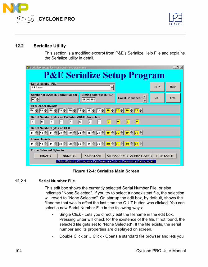
104 Cyclone PRO User Manual
CYCLONE PRO
12.2 Serialize UtilityThis section is a modified excerpt from P&E’s Serialize Help File and explains the Serialize utility in detail.
Figure 12-4: Serialize Main Screen
12.2.1 Serial Number FileThis edit box shows the currently selected Serial Number File, or else indicates "None Selected". If you try to select a nonexistent file, the selection will revert to "None Selected". On startup the edit box, by default, shows the filename that was in effect the last time the QUIT button was clicked. You can select a new Serial Number File in the following ways:
• Single Click - Lets you directly edit the filename in the edit box. Pressing Enter will check for the existence of the file. If not found, the selected file gets set to "None Selected". If the file exists, the serial number and its properties are displayed on screen.
• Double Click or …Click - Opens a standard file browser and lets you
Cyclone PRO User Manual 105
CYCLONE PRO
choose from existing files by disk, directory, name, and extension.
12.2.2 Number of Bytes in Serial NumberThe up and down arrows let you add or delete bytes for the serial number, max=10 hex (16 base ten), min=1.
• Up Arrow Click - Adds new bytes to the Serial Number. Each byte added appears as a new column in the serial number representation. Added bytes are input as Binary Bytes, i.e. the upper bound is FF and the lower bound is 00.
• Down Arrow Click - Deletes bytes from the right end of the Serial Number. Any previously entered byte properties are lost.
12.2.3 Count SequenceThis window lets you count up or down through the sequencing of the serial number. The serial number is allowed to wrap over the top of the highest serial number or below the lowest serial number. Note that in P&E programmers, the serial number can only count up and any attempt to overflow will cause an error.
• Up Arrow Click - Counts the serial number up.
• Down Arrow Click - Counts the serial number down.
12.2.4 Serial Number Bytes as HexThere is one display column for each byte in the serial number shown as printable ASCII characters. Non-printable ASCII characters are indicated by the small solid block graphic.
• Up Arrow Click - Counts the serial number up.
• Down Arrow Click - Counts the serial number down.
12.2.5 Hex Upper BoundsThere is one display column for each upper bound of the byte in the serial number in hex.
• Up Arrow Click - Increases the upper bound by one with a maximum of FF Hex.
• Down Arrow Click - Decreases the upper bound by one with a minimum of the current serial number byte value.

106 Cyclone PRO User Manual
CYCLONE PRO
• Double Click on Hex - Selects or deselects the byte column. Selected shown in yellow. The serial number byte in this column may then be modified using the buttons at the bottom of the Serialize utility. Please refer to Section 12.2.11 - BINARY, NUMERIC, CONSTANT, ALPHA UPPER, ALPHA LOWER, and PRINTABLE.
12.2.6 Hex Lower BoundsThere is one display column for each byte of the lower bound of the serial number in hex.
• Up Arrow Click - Increases the lower bound by one with a maximum of the current serial number byte value.
• Down Arrow Click - Decreases the lower bound by one with a minimum of 00 Hex.
12.2.7 NEWInstructs the program to start editing a NEW (as yet un-named) serial number file. It will throw away the information for any serial number currently being edited unless that information has been saved (Save Button). The new serial number is initialized with one (1) byte of binary.
12.2.8 SAVEInstructs the program to save the current serial number being edited into the file name and path shown in the Serial Number File window. If a file name has not been provided, i.e. the window shows None Selected, then an error is displayed in a red window on the screen. If this happens, type in a filename in the window and click Save again.
12.2.9 HELPOpens the Serialize help system (serialize.hlp file, i.e. this file) for perusal.
12.2.10 QUITTurns off the Serialize Program and saves any setup information in the file Serialize.ini. This file will initialize the setup information the next time the program is started. Xing out of the program (top right of screen) does not save the setup info.
12.2.11 BINARY, NUMERIC, CONSTANT, ALPHA UPPER, ALPHA LOWER, and
Cyclone PRO User Manual 107
CYCLONE PRO
PRINTABLE These buttons are used to set the properties of selected (colored yellow) bytes of the Serial Number. Individual bytes whose properties you wish to modify are selected or deselected by double-clicking in the Hex Upper Bounds box in the column that corresponds with the values for a particular byte.
12.3 Serialize Utility ExampleThis example shows:
1. Currently editing file C:\Example.ser
2. Number of bytes in the serial number is 10 Hex (= 16 base ten)
3. Starting address is 0000000 Hex
4. Next Serial number is AAA-P&E-9999 in ASCII
a. First 3 bytes are Upper Case Alphabetic ASCII (AAA)
b. Next 5 bytes are Constants (-P&E-)
c. Last 4 bytes are Numeric ASCII (9999)
5. This provides for a maximum of 6,760,000 (26x26x26x10x10x10x10) serial numbers from AAA-P&E-0000 to ZZZ-P&E-9999.
6. The last 4 bytes of the serial number are selected (colored yellow) so that their properties can be changed using the forced selected byte buttons on the bottom of the screen.
12.4 Using Serial Number FileThe command to invoke the serial number file in P&E’s interactive programming software is “CS Choose Serial File”. The command to actually program the serial number to target and automatically increment the serial number afterward is “PS Program Serial Number”.P&E’s command line software uses the same commands in a command line fashion to invoke the serial number file, initiate its programming, and increment:
CS serial_number_file.serPS
108 Cyclone PRO User Manual
CYCLONE PRO
12.5 Serial Number Handling in Cyclone PROThe Cyclone PRO’s firmware implements the automatic serial number mechanism. The same serial number files are used with the Cyclone Image Creation Utility, and the same commands are used to specify the serial number file and initiate serial number programming and incrementation. The serial number data structure is saved in the SAP image. Once a serial number is programmed, the Cyclone PRO firmware automatically increments the serial number and stores it in the Cyclone PRO’s flash for internal images or external CompactFlash for external SAP images.The CS and PS commands are not present in the Cyclone Image Creation Utility until a valid programming algorithm is specified.To complement the Cyclone’s usage in production environments, the Cyclone PRO supports multiple serial number structures for each programming algorithm block. Each SAP image may contain multiple programming algorithms for every memory module it needs to program, and each programming algorithm block may contain multiple serial number structures. The SAP image sequence below illustrates this briefly:
CM algorithm_file_1SS object_code_1ENPMVCCS serial_file1.serPSCS serial_file2.serPSCS serial_file_3.serPSCM algorithm_file_2SS object_code_2ENPMVC
Cyclone PRO User Manual 109
CYCLONE PRO
CS serial_file4.serPSCS serial_file5.serPS
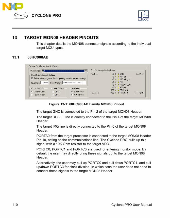
110 Cyclone PRO User Manual
CYCLONE PRO
13 TARGET MON08 HEADER PINOUTSThis chapter details the MON08 connector signals according to the individual target MCU types.
13.1 68HC908AB
Figure 13-1: 68HC908AB Family MON08 Pinout
The target GND is connected to the Pin 2 of the target MON08 Header.The target RESET line is directly connected to the Pin 4 of the target MON08 Header. The target IRQ line is directly connected to the Pin 6 of the target MON08 Header.PORTA0 from the target processor is connected to the target MON08 Header Pin 10, acting as the communications line. The Cyclone PRO pulls up this signal with a 10K Ohm resistor to the target VDD.PORTC0, PORTC1 and PORTC3 are used for entering monitor mode. By default the user may directly bring these signals out to the target MON08 Header.Alternatively, the user may pull up PORTC0 and pull down PORTC1, and pull up/down PORTC3 for clock division. In which case the user does not need to connect these signals to the target MON08 Header.

Cyclone PRO User Manual 111
CYCLONE PRO
13.2 68HC908AP
Figure 13-2: 68HC908AP Family MON08 Pinout
The target GND is connected to the Pin 2 of the target MON08 Header.The target RESET line is directly connected to the Pin 4 of the target MON08 Header. The target IRQ line is directly connected to the Pin 6 of the target MON08 Header.PORTA0 from the target processor is connected to the target MON08 Header Pin 10, acting as the communications line. The Cyclone PRO pulls up this signal with a 10K Ohm resistor to the target VDD.PORTA2, PORTA1 and PORTB0 are used for entering monitor mode. By default the user may bring these signals out to the target MON08 Header.Alternatively, the user may pull down PORTA2 and pull up PORTA1, and pull up/down PORTB0 for clock division. In which case the user does not need to connect these signals to the target MON08 Header.
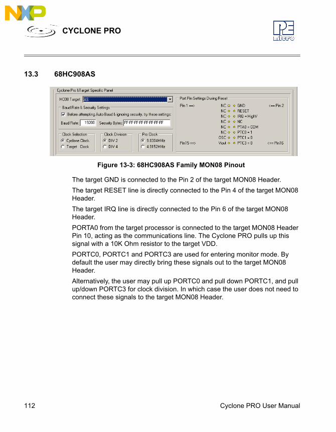
112 Cyclone PRO User Manual
CYCLONE PRO
13.3 68HC908AS
Figure 13-3: 68HC908AS Family MON08 Pinout
The target GND is connected to the Pin 2 of the target MON08 Header.The target RESET line is directly connected to the Pin 4 of the target MON08 Header. The target IRQ line is directly connected to the Pin 6 of the target MON08 Header.PORTA0 from the target processor is connected to the target MON08 Header Pin 10, acting as the communications line. The Cyclone PRO pulls up this signal with a 10K Ohm resistor to the target VDD.PORTC0, PORTC1 and PORTC3 are used for entering monitor mode. By default the user may directly bring these signals out to the target MON08 Header.Alternatively, the user may pull up PORTC0 and pull down PORTC1, and pull up/down PORTC3 for clock division. In which case the user does not need to connect these signals to the target MON08 Header.
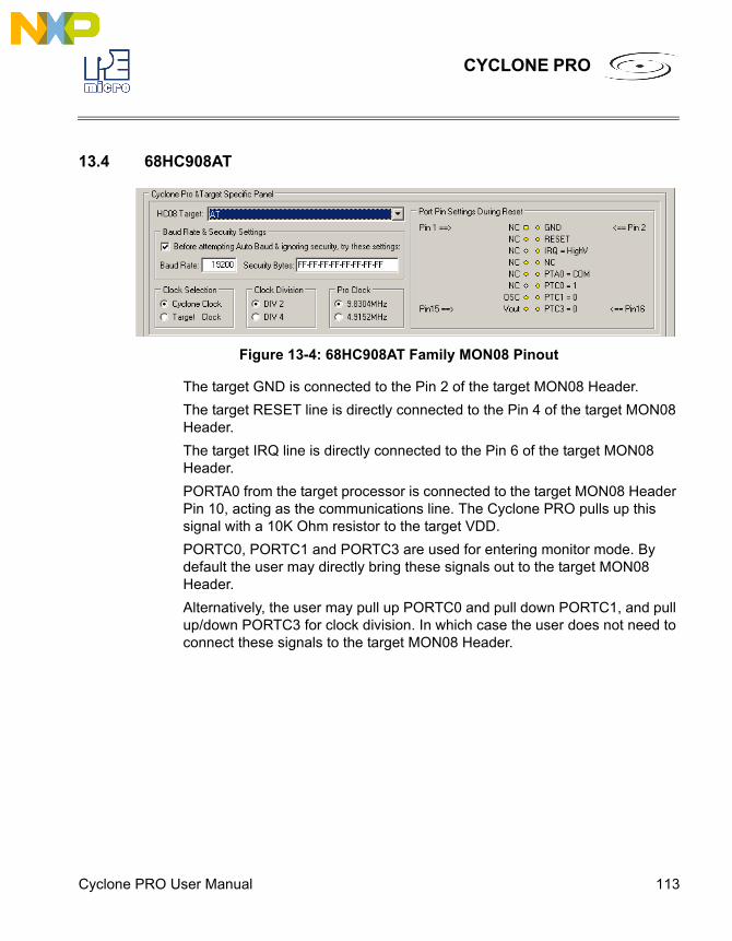
Cyclone PRO User Manual 113
CYCLONE PRO
13.4 68HC908AT
Figure 13-4: 68HC908AT Family MON08 Pinout
The target GND is connected to the Pin 2 of the target MON08 Header.The target RESET line is directly connected to the Pin 4 of the target MON08 Header. The target IRQ line is directly connected to the Pin 6 of the target MON08 Header.PORTA0 from the target processor is connected to the target MON08 Header Pin 10, acting as the communications line. The Cyclone PRO pulls up this signal with a 10K Ohm resistor to the target VDD.PORTC0, PORTC1 and PORTC3 are used for entering monitor mode. By default the user may directly bring these signals out to the target MON08 Header.Alternatively, the user may pull up PORTC0 and pull down PORTC1, and pull up/down PORTC3 for clock division. In which case the user does not need to connect these signals to the target MON08 Header.

114 Cyclone PRO User Manual
CYCLONE PRO
13.5 68HC908AZ
Figure 13-5: 68HC908AZ Family MON08 Pinout
The target GND is connected to the Pin 2 of the target MON08 Header.The target RESET line is directly connected to the Pin 4 of the target MON08 Header. The target IRQ line is directly connected to the Pin 6 of the target MON08 Header.PORTA0 from the target processor is connected to the target MON08 Header Pin 10, acting as the communications line. The Cyclone PRO pulls up this signal with a 10K Ohm resistor to the target VDD.PORTC0, PORTC1 and PORTC3 are used for entering monitor mode. By default the user may directly bring these signals out to the target MON08 Header.Alternatively, the user may pull up PORTC0 and pull down PORTC1, and pull up/down PORTC3 for clock division. In which case the user does not need to connect these signals to the target MON08 Header.

Cyclone PRO User Manual 115
CYCLONE PRO
13.6 68HC908BD
Figure 13-6: 68HC908BD Family MON08 Pinout
The target GND is connected to the Pin 2 of the target MON08 Header.The target RESET line is directly connected to the Pin 4 of the target MON08 Header. The target IRQ line is directly connected to the Pin 6 of the target MON08 Header.PORTA0 from the target processor is connected to the target MON08 Header Pin 10, acting as the communications line. The Cyclone PRO pulls up this signal with a 10K Ohm resistor to the target VDD.PORTC0, PORTC1 and PORTC3 are used for entering monitor mode. By default the user may directly bring these signals out to the target MON08 Header.Alternatively, the user may pull up PORTC0 and pull down PORTC1, and pull up/down PORTC3 for clock division. In which case the user does not need to connect these signals to the target MON08 Header.
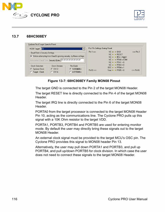
116 Cyclone PRO User Manual
CYCLONE PRO
13.7 68HC908EY
Figure 13-7: 68HC908EY Family MON08 Pinout
The target GND is connected to the Pin 2 of the target MON08 Header.The target RESET line is directly connected to the Pin 4 of the target MON08 Header. The target IRQ line is directly connected to the Pin 6 of the target MON08 Header.PORTA0 from the target processor is connected to the target MON08 Header Pin 10, acting as the communications line. The Cyclone PRO pulls up this signal with a 10K Ohm resistor to the target VDD.PORTA1, PORTB3, PORTB4 and PORTB5 are used for entering monitor mode. By default the user may directly bring these signals out to the target MON08 Header.An external clock signal must be provided to the target MCU’s OSC pin. The Cyclone PRO provides this signal to MON08 header Pin 13.Alternatively, the user may pull down PORTA1 and PORTB3, and pull up PORTB4, and pull up/down PORTB5 for clock division. In which case the user does not need to connect these signals to the target MON08 Header.
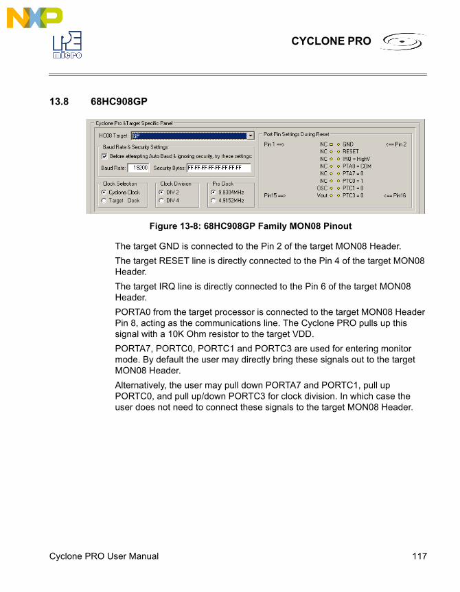
Cyclone PRO User Manual 117
CYCLONE PRO
13.8 68HC908GP
Figure 13-8: 68HC908GP Family MON08 Pinout
The target GND is connected to the Pin 2 of the target MON08 Header.The target RESET line is directly connected to the Pin 4 of the target MON08 Header. The target IRQ line is directly connected to the Pin 6 of the target MON08 Header.PORTA0 from the target processor is connected to the target MON08 Header Pin 8, acting as the communications line. The Cyclone PRO pulls up this signal with a 10K Ohm resistor to the target VDD.PORTA7, PORTC0, PORTC1 and PORTC3 are used for entering monitor mode. By default the user may directly bring these signals out to the target MON08 Header.Alternatively, the user may pull down PORTA7 and PORTC1, pull up PORTC0, and pull up/down PORTC3 for clock division. In which case the user does not need to connect these signals to the target MON08 Header.
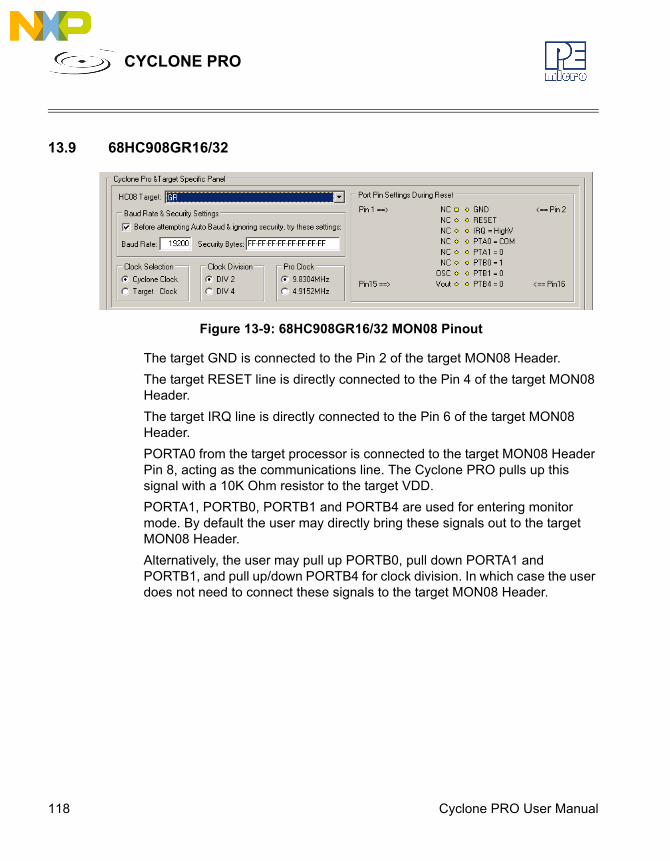
118 Cyclone PRO User Manual
CYCLONE PRO
13.9 68HC908GR16/32
Figure 13-9: 68HC908GR16/32 MON08 Pinout
The target GND is connected to the Pin 2 of the target MON08 Header.The target RESET line is directly connected to the Pin 4 of the target MON08 Header. The target IRQ line is directly connected to the Pin 6 of the target MON08 Header.PORTA0 from the target processor is connected to the target MON08 Header Pin 8, acting as the communications line. The Cyclone PRO pulls up this signal with a 10K Ohm resistor to the target VDD.PORTA1, PORTB0, PORTB1 and PORTB4 are used for entering monitor mode. By default the user may directly bring these signals out to the target MON08 Header.Alternatively, the user may pull up PORTB0, pull down PORTA1 and PORTB1, and pull up/down PORTB4 for clock division. In which case the user does not need to connect these signals to the target MON08 Header.
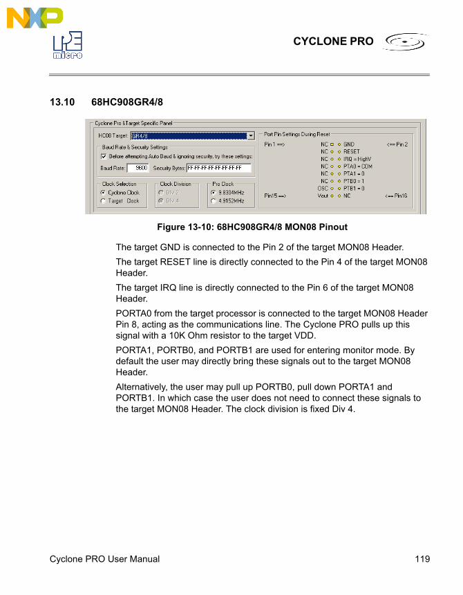
Cyclone PRO User Manual 119
CYCLONE PRO
13.10 68HC908GR4/8
Figure 13-10: 68HC908GR4/8 MON08 Pinout
The target GND is connected to the Pin 2 of the target MON08 Header.The target RESET line is directly connected to the Pin 4 of the target MON08 Header. The target IRQ line is directly connected to the Pin 6 of the target MON08 Header.PORTA0 from the target processor is connected to the target MON08 Header Pin 8, acting as the communications line. The Cyclone PRO pulls up this signal with a 10K Ohm resistor to the target VDD.PORTA1, PORTB0, and PORTB1 are used for entering monitor mode. By default the user may directly bring these signals out to the target MON08 Header.Alternatively, the user may pull up PORTB0, pull down PORTA1 and PORTB1. In which case the user does not need to connect these signals to the target MON08 Header. The clock division is fixed Div 4.

120 Cyclone PRO User Manual
CYCLONE PRO
13.11 68HC908GT
Figure 13-11: 68HC908GT Family MON08 Pinout
The target GND is connected to the Pin 2 of the target MON08 Header.The target RESET line is directly connected to the Pin 4 of the target MON08 Header. The target IRQ line is directly connected to the Pin 6 of the target MON08 Header.PORTA0 from the target processor is connected to the target MON08 Header Pin 8, acting as the communications line. The Cyclone PRO pulls up this signal with a 10K Ohm resistor to the target VDD.PORTC0, PORTC1 and PORTC3 are used for entering monitor mode. By default the user may directly bring these signals out to the target MON08 Header.Alternatively, the user may pull up PORTC0 and pull down PORTC1, and pull up/down PORTC3 for clock division. In which case the user does not need to connect these signals to the target MON08 Header.
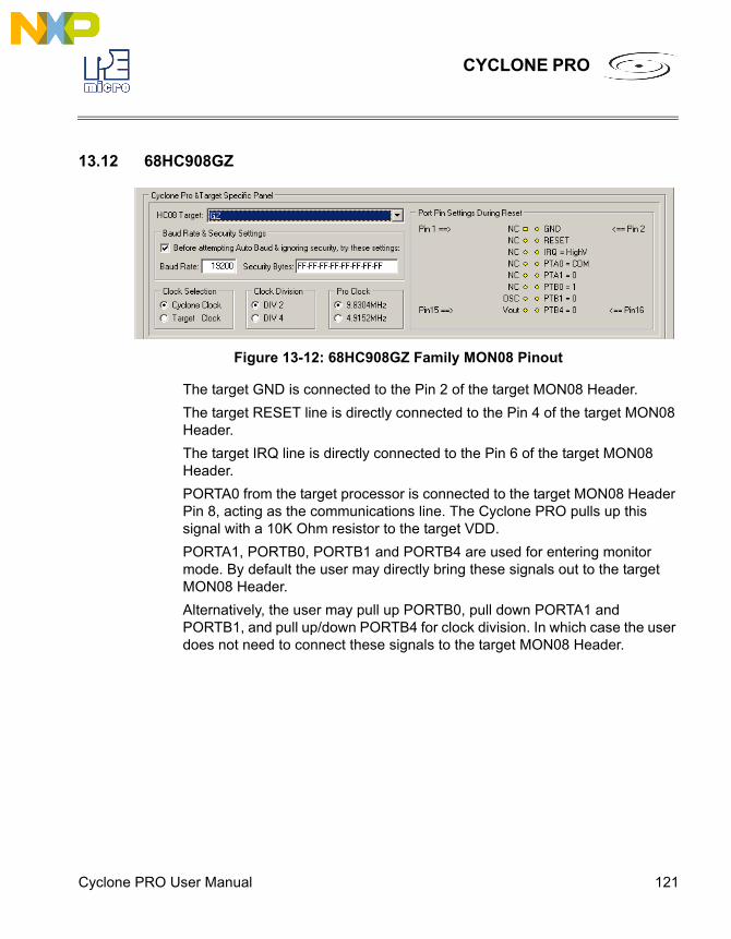
Cyclone PRO User Manual 121
CYCLONE PRO
13.12 68HC908GZ
Figure 13-12: 68HC908GZ Family MON08 Pinout
The target GND is connected to the Pin 2 of the target MON08 Header.The target RESET line is directly connected to the Pin 4 of the target MON08 Header. The target IRQ line is directly connected to the Pin 6 of the target MON08 Header.PORTA0 from the target processor is connected to the target MON08 Header Pin 8, acting as the communications line. The Cyclone PRO pulls up this signal with a 10K Ohm resistor to the target VDD.PORTA1, PORTB0, PORTB1 and PORTB4 are used for entering monitor mode. By default the user may directly bring these signals out to the target MON08 Header.Alternatively, the user may pull up PORTB0, pull down PORTA1 and PORTB1, and pull up/down PORTB4 for clock division. In which case the user does not need to connect these signals to the target MON08 Header.

122 Cyclone PRO User Manual
CYCLONE PRO
13.13 68HC908JB1/8
Figure 13-13: 68HC908JB1/8 MON08 Pinout
The target GND is connected to the Pin 2 of the target MON08 Header.The target RESET line is directly connected to the Pin 4 of the target MON08 Header. The target IRQ line is directly connected to the Pin 6 of the target MON08 Header.PORTA0 from the target processor is connected to the target MON08 Header Pin 10, acting as the communications line. The Cyclone PRO pulls up this signal with a 10K Ohm resistor to the target VDD.PORTA1, PORTA2 and PORTA3 are used for entering monitor mode. By default the user may directly bring these signals out to the target MON08 Header.Alternatively, the user may pull up PORTA1 and pull down PORTA2, and pull up/down PORTA3 for clock division. In which case the user does not need to connect these signals to the target MON08 Header.
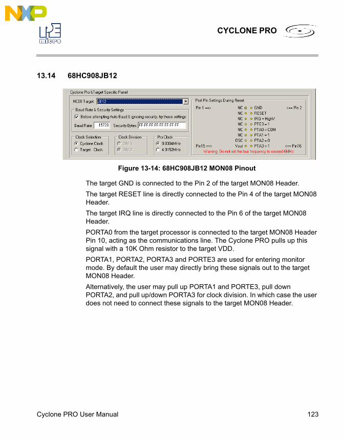
Cyclone PRO User Manual 123
CYCLONE PRO
13.14 68HC908JB12
Figure 13-14: 68HC908JB12 MON08 Pinout
The target GND is connected to the Pin 2 of the target MON08 Header.The target RESET line is directly connected to the Pin 4 of the target MON08 Header. The target IRQ line is directly connected to the Pin 6 of the target MON08 Header.PORTA0 from the target processor is connected to the target MON08 Header Pin 10, acting as the communications line. The Cyclone PRO pulls up this signal with a 10K Ohm resistor to the target VDD.PORTA1, PORTA2, PORTA3 and PORTE3 are used for entering monitor mode. By default the user may directly bring these signals out to the target MON08 Header.Alternatively, the user may pull up PORTA1 and PORTE3, pull down PORTA2, and pull up/down PORTA3 for clock division. In which case the user does not need to connect these signals to the target MON08 Header.
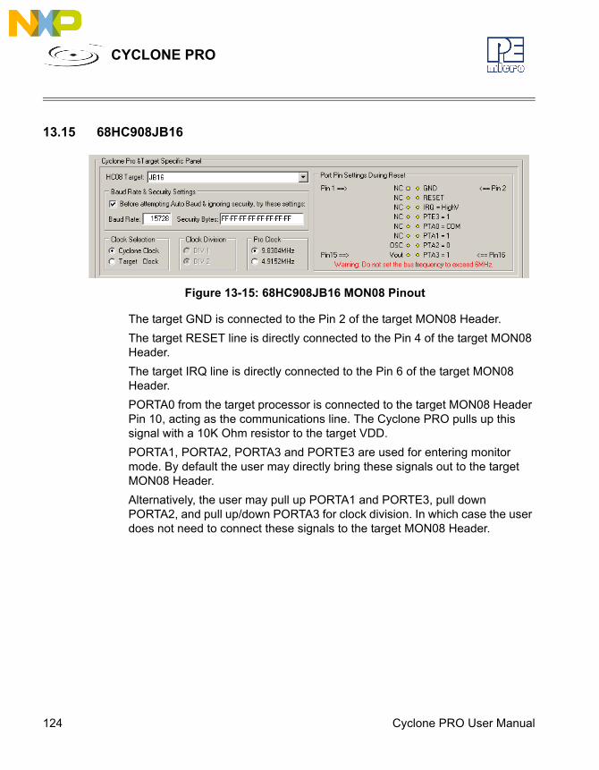
124 Cyclone PRO User Manual
CYCLONE PRO
13.15 68HC908JB16
Figure 13-15: 68HC908JB16 MON08 Pinout
The target GND is connected to the Pin 2 of the target MON08 Header.The target RESET line is directly connected to the Pin 4 of the target MON08 Header. The target IRQ line is directly connected to the Pin 6 of the target MON08 Header.PORTA0 from the target processor is connected to the target MON08 Header Pin 10, acting as the communications line. The Cyclone PRO pulls up this signal with a 10K Ohm resistor to the target VDD.PORTA1, PORTA2, PORTA3 and PORTE3 are used for entering monitor mode. By default the user may directly bring these signals out to the target MON08 Header.Alternatively, the user may pull up PORTA1 and PORTE3, pull down PORTA2, and pull up/down PORTA3 for clock division. In which case the user does not need to connect these signals to the target MON08 Header.
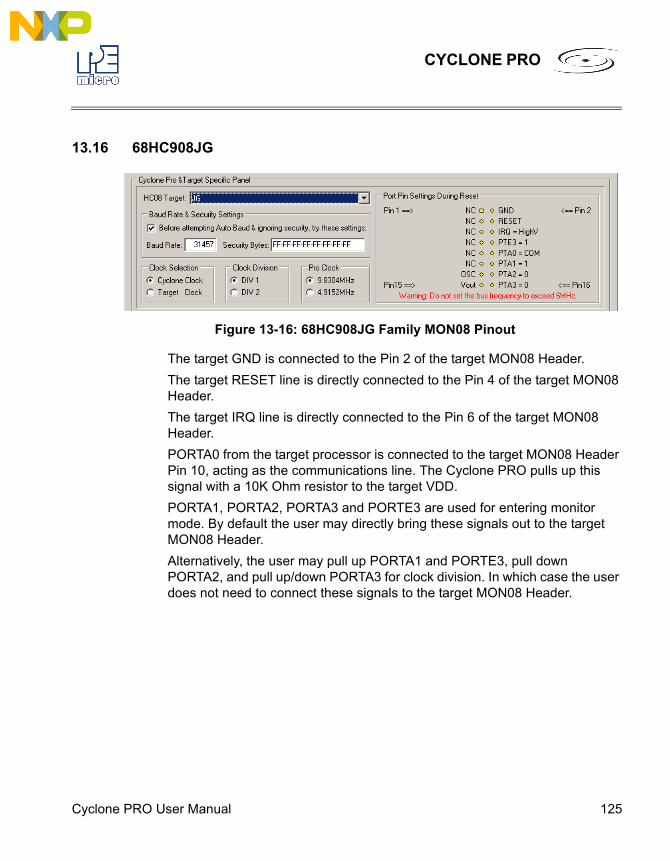
Cyclone PRO User Manual 125
CYCLONE PRO
13.16 68HC908JG
Figure 13-16: 68HC908JG Family MON08 Pinout
The target GND is connected to the Pin 2 of the target MON08 Header.The target RESET line is directly connected to the Pin 4 of the target MON08 Header. The target IRQ line is directly connected to the Pin 6 of the target MON08 Header.PORTA0 from the target processor is connected to the target MON08 Header Pin 10, acting as the communications line. The Cyclone PRO pulls up this signal with a 10K Ohm resistor to the target VDD.PORTA1, PORTA2, PORTA3 and PORTE3 are used for entering monitor mode. By default the user may directly bring these signals out to the target MON08 Header.Alternatively, the user may pull up PORTA1 and PORTE3, pull down PORTA2, and pull up/down PORTA3 for clock division. In which case the user does not need to connect these signals to the target MON08 Header.
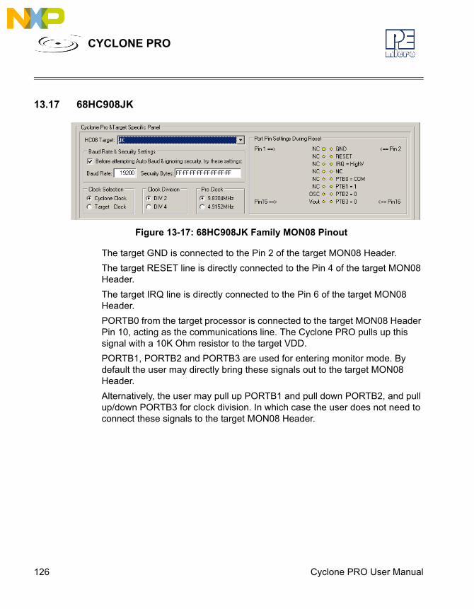
126 Cyclone PRO User Manual
CYCLONE PRO
13.17 68HC908JK
Figure 13-17: 68HC908JK Family MON08 Pinout
The target GND is connected to the Pin 2 of the target MON08 Header.The target RESET line is directly connected to the Pin 4 of the target MON08 Header. The target IRQ line is directly connected to the Pin 6 of the target MON08 Header.PORTB0 from the target processor is connected to the target MON08 Header Pin 10, acting as the communications line. The Cyclone PRO pulls up this signal with a 10K Ohm resistor to the target VDD.PORTB1, PORTB2 and PORTB3 are used for entering monitor mode. By default the user may directly bring these signals out to the target MON08 Header.Alternatively, the user may pull up PORTB1 and pull down PORTB2, and pull up/down PORTB3 for clock division. In which case the user does not need to connect these signals to the target MON08 Header.

Cyclone PRO User Manual 127
CYCLONE PRO
13.18 68HC908JL
Figure 13-18: 68HC908JL Family MON08 Pinout
The target GND is connected to the Pin 2 of the target MON08 Header.The target RESET line is directly connected to the Pin 4 of the target MON08 Header. The target IRQ line is directly connected to the Pin 6 of the target MON08 Header.PORTB0 from the target processor is connected to the target MON08 Header Pin 10, acting as the communications line. The Cyclone PRO pulls up this signal with a 10K Ohm resistor to the target VDD.PORTB1, PORTB2 and PORTB3 are used for entering monitor mode. By default the user may directly bring these signals out to the target MON08 Header.Alternatively, the user may pull up PORTB1 and pull down PORTB2, and pull up/down PORTB3 for clock division. In which case the user does not need to connect these signals to the target MON08 Header.
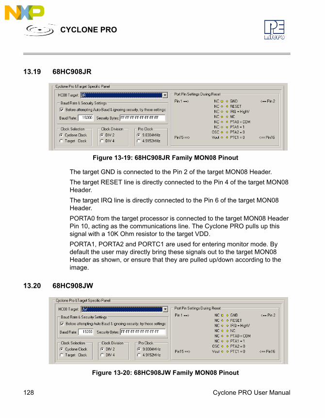
128 Cyclone PRO User Manual
CYCLONE PRO
13.19 68HC908JR
Figure 13-19: 68HC908JR Family MON08 Pinout
The target GND is connected to the Pin 2 of the target MON08 Header.The target RESET line is directly connected to the Pin 4 of the target MON08 Header. The target IRQ line is directly connected to the Pin 6 of the target MON08 Header.PORTA0 from the target processor is connected to the target MON08 Header Pin 10, acting as the communications line. The Cyclone PRO pulls up this signal with a 10K Ohm resistor to the target VDD.PORTA1, PORTA2 and PORTC1 are used for entering monitor mode. By default the user may directly bring these signals out to the target MON08 Header as shown, or ensure that they are pulled up/down according to the image.
13.20 68HC908JW
Figure 13-20: 68HC908JW Family MON08 Pinout
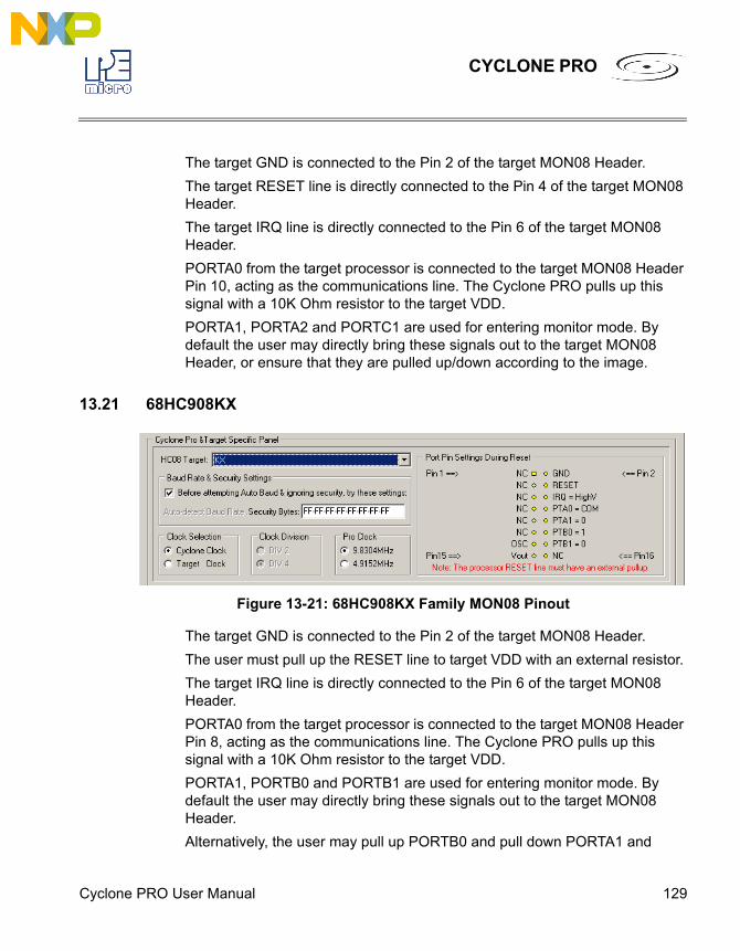
Cyclone PRO User Manual 129
CYCLONE PRO
The target GND is connected to the Pin 2 of the target MON08 Header.The target RESET line is directly connected to the Pin 4 of the target MON08 Header. The target IRQ line is directly connected to the Pin 6 of the target MON08 Header.PORTA0 from the target processor is connected to the target MON08 Header Pin 10, acting as the communications line. The Cyclone PRO pulls up this signal with a 10K Ohm resistor to the target VDD.PORTA1, PORTA2 and PORTC1 are used for entering monitor mode. By default the user may directly bring these signals out to the target MON08 Header, or ensure that they are pulled up/down according to the image.
13.21 68HC908KX
Figure 13-21: 68HC908KX Family MON08 Pinout
The target GND is connected to the Pin 2 of the target MON08 Header.The user must pull up the RESET line to target VDD with an external resistor. The target IRQ line is directly connected to the Pin 6 of the target MON08 Header.PORTA0 from the target processor is connected to the target MON08 Header Pin 8, acting as the communications line. The Cyclone PRO pulls up this signal with a 10K Ohm resistor to the target VDD.PORTA1, PORTB0 and PORTB1 are used for entering monitor mode. By default the user may directly bring these signals out to the target MON08 Header.Alternatively, the user may pull up PORTB0 and pull down PORTA1 and
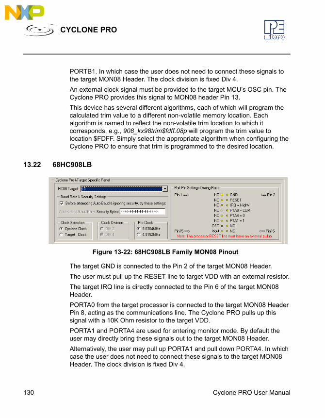
130 Cyclone PRO User Manual
CYCLONE PRO
PORTB1. In which case the user does not need to connect these signals to the target MON08 Header. The clock division is fixed Div 4.An external clock signal must be provided to the target MCU’s OSC pin. The Cyclone PRO provides this signal to MON08 header Pin 13.This device has several different algorithms, each of which will program the calculated trim value to a different non-volatile memory location. Each algorithm is named to reflect the non-volatile trim location to which it corresponds, e.g., 908_kx98trim$fdff.08p will program the trim value to location $FDFF. Simply select the appropriate algorithm when configuring the Cyclone PRO to ensure that trim is programmed to the desired location.
13.22 68HC908LB
Figure 13-22: 68HC908LB Family MON08 Pinout
The target GND is connected to the Pin 2 of the target MON08 Header.The user must pull up the RESET line to target VDD with an external resistor.The target IRQ line is directly connected to the Pin 6 of the target MON08 Header.PORTA0 from the target processor is connected to the target MON08 Header Pin 8, acting as the communications line. The Cyclone PRO pulls up this signal with a 10K Ohm resistor to the target VDD.PORTA1 and PORTA4 are used for entering monitor mode. By default the user may directly bring these signals out to the target MON08 Header.Alternatively, the user may pull up PORTA1 and pull down PORTA4. In which case the user does not need to connect these signals to the target MON08 Header. The clock division is fixed Div 4.
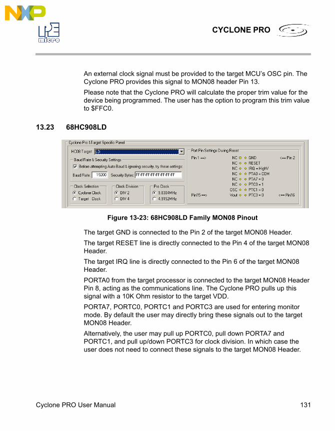
Cyclone PRO User Manual 131
CYCLONE PRO
An external clock signal must be provided to the target MCU’s OSC pin. The Cyclone PRO provides this signal to MON08 header Pin 13.Please note that the Cyclone PRO will calculate the proper trim value for the device being programmed. The user has the option to program this trim value to $FFC0.
13.23 68HC908LD
Figure 13-23: 68HC908LD Family MON08 Pinout
The target GND is connected to the Pin 2 of the target MON08 Header.The target RESET line is directly connected to the Pin 4 of the target MON08 Header. The target IRQ line is directly connected to the Pin 6 of the target MON08 Header.PORTA0 from the target processor is connected to the target MON08 Header Pin 8, acting as the communications line. The Cyclone PRO pulls up this signal with a 10K Ohm resistor to the target VDD.PORTA7, PORTC0, PORTC1 and PORTC3 are used for entering monitor mode. By default the user may directly bring these signals out to the target MON08 Header.Alternatively, the user may pull up PORTC0, pull down PORTA7 and PORTC1, and pull up/down PORTC3 for clock division. In which case the user does not need to connect these signals to the target MON08 Header.

132 Cyclone PRO User Manual
CYCLONE PRO
13.24 68HC908LJ
Figure 13-24: 68HC908LJ Family MON08 Pinout
The target GND is connected to the Pin 2 of the target MON08 Header.The target RESET line is directly connected to the Pin 4 of the target MON08 Header. The target IRQ line is directly connected to the Pin 6 of the target MON08 Header.PORTA0 from the target processor is connected to the target MON08 Header Pin 10, acting as the communications line. The Cyclone PRO pulls up this signal with a 10K Ohm resistor to the target VDD.PORTA1, PORTA2 and PORTC1 are used for entering monitor mode. By default the user may directly bring these signals out to the target MON08 Header.Alternatively, the user may pull up PORTA1 and pull down PORTA2, and pull up/down PORTC1 for clock division. In which case the user does not need to connect these signals to the target MON08 Header.
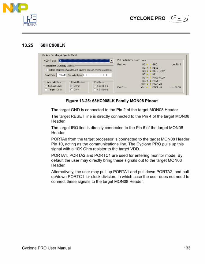
Cyclone PRO User Manual 133
CYCLONE PRO
13.25 68HC908LK
Figure 13-25: 68HC908LK Family MON08 Pinout
The target GND is connected to the Pin 2 of the target MON08 Header.The target RESET line is directly connected to the Pin 4 of the target MON08 Header. The target IRQ line is directly connected to the Pin 6 of the target MON08 Header.PORTA0 from the target processor is connected to the target MON08 Header Pin 10, acting as the communications line. The Cyclone PRO pulls up this signal with a 10K Ohm resistor to the target VDD.PORTA1, PORTA2 and PORTC1 are used for entering monitor mode. By default the user may directly bring these signals out to the target MON08 Header.Alternatively, the user may pull up PORTA1 and pull down PORTA2, and pull up/down PORTC1 for clock division. In which case the user does not need to connect these signals to the target MON08 Header.
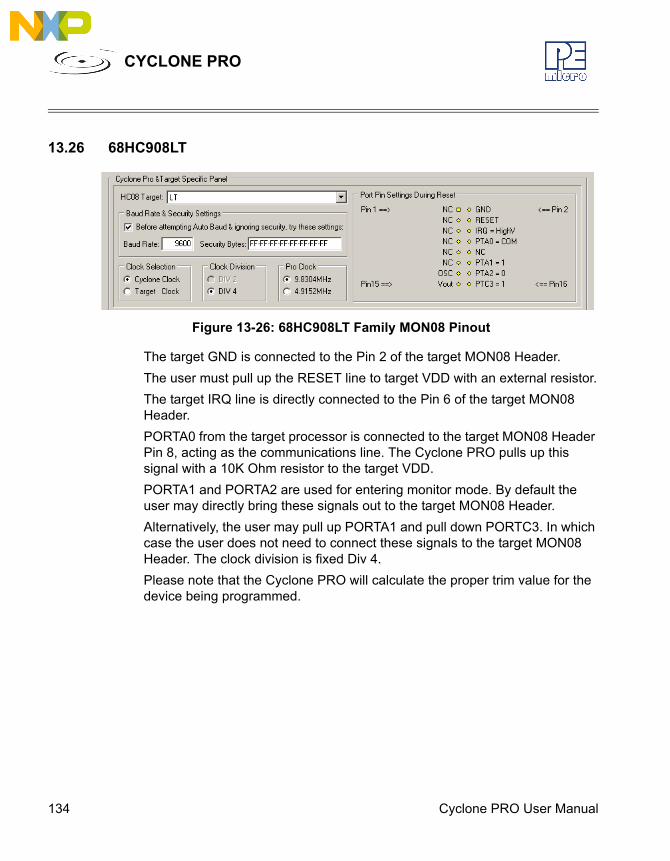
134 Cyclone PRO User Manual
CYCLONE PRO
13.26 68HC908LT
Figure 13-26: 68HC908LT Family MON08 Pinout
The target GND is connected to the Pin 2 of the target MON08 Header.The user must pull up the RESET line to target VDD with an external resistor.The target IRQ line is directly connected to the Pin 6 of the target MON08 Header.PORTA0 from the target processor is connected to the target MON08 Header Pin 8, acting as the communications line. The Cyclone PRO pulls up this signal with a 10K Ohm resistor to the target VDD.PORTA1 and PORTA2 are used for entering monitor mode. By default the user may directly bring these signals out to the target MON08 Header.Alternatively, the user may pull up PORTA1 and pull down PORTC3. In which case the user does not need to connect these signals to the target MON08 Header. The clock division is fixed Div 4.Please note that the Cyclone PRO will calculate the proper trim value for the device being programmed.
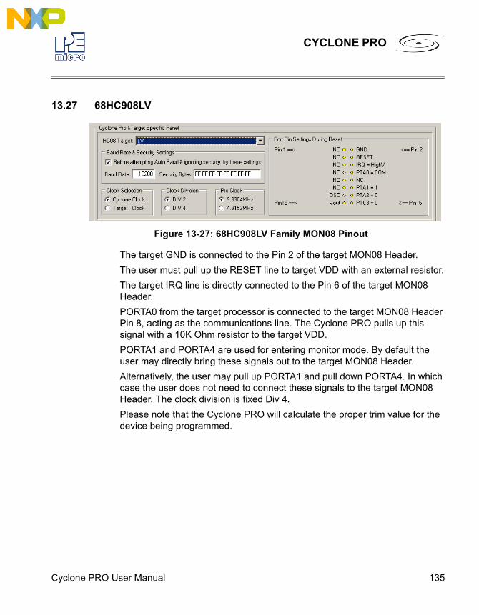
Cyclone PRO User Manual 135
CYCLONE PRO
13.27 68HC908LV
Figure 13-27: 68HC908LV Family MON08 Pinout
The target GND is connected to the Pin 2 of the target MON08 Header.The user must pull up the RESET line to target VDD with an external resistor.The target IRQ line is directly connected to the Pin 6 of the target MON08 Header.PORTA0 from the target processor is connected to the target MON08 Header Pin 8, acting as the communications line. The Cyclone PRO pulls up this signal with a 10K Ohm resistor to the target VDD.PORTA1 and PORTA4 are used for entering monitor mode. By default the user may directly bring these signals out to the target MON08 Header.Alternatively, the user may pull up PORTA1 and pull down PORTA4. In which case the user does not need to connect these signals to the target MON08 Header. The clock division is fixed Div 4.Please note that the Cyclone PRO will calculate the proper trim value for the device being programmed.
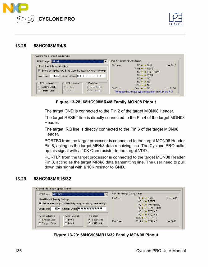
136 Cyclone PRO User Manual
CYCLONE PRO
13.28 68HC908MR4/8
Figure 13-28: 68HC908MR4/8 Family MON08 Pinout
The target GND is connected to the Pin 2 of the target MON08 Header.The target RESET line is directly connected to the Pin 4 of the target MON08 Header. The target IRQ line is directly connected to the Pin 6 of the target MON08 Header.PORTB0 from the target processor is connected to the target MON08 Header Pin 8, acting as the target MR4/8 data receiving line. The Cyclone PRO pulls up this signal with a 10K Ohm resistor to the target VDD.PORTB1 from the target processor is connected to the target MON08 Header Pin 3, acting as the target MR4/8 data transmitting line. The user need to pull down this signal with a 10K resistor to GND.
13.29 68HC908MR16/32
Figure 13-29: 68HC908MR16/32 Family MON08 Pinout
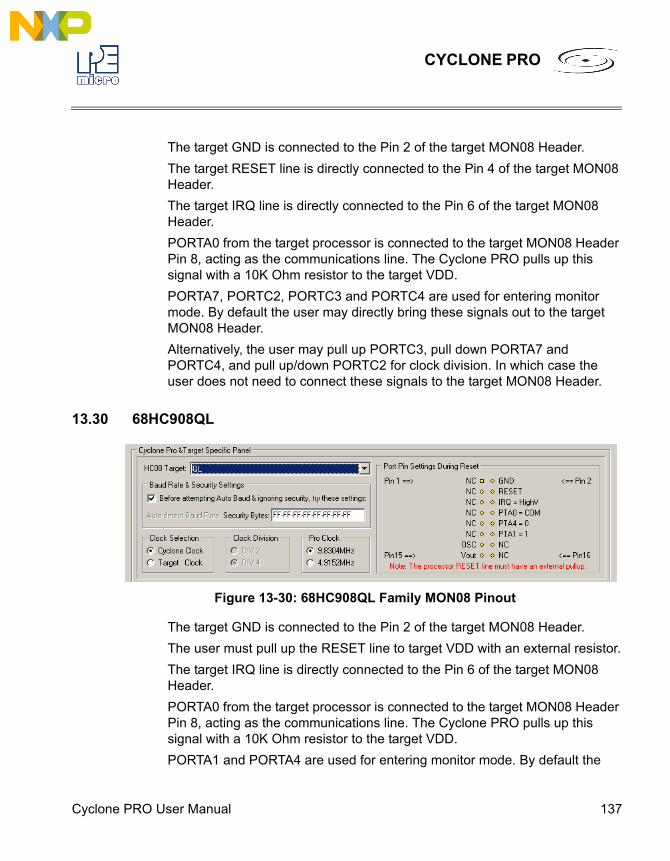
Cyclone PRO User Manual 137
CYCLONE PRO
The target GND is connected to the Pin 2 of the target MON08 Header.The target RESET line is directly connected to the Pin 4 of the target MON08 Header. The target IRQ line is directly connected to the Pin 6 of the target MON08 Header.PORTA0 from the target processor is connected to the target MON08 Header Pin 8, acting as the communications line. The Cyclone PRO pulls up this signal with a 10K Ohm resistor to the target VDD.PORTA7, PORTC2, PORTC3 and PORTC4 are used for entering monitor mode. By default the user may directly bring these signals out to the target MON08 Header.Alternatively, the user may pull up PORTC3, pull down PORTA7 and PORTC4, and pull up/down PORTC2 for clock division. In which case the user does not need to connect these signals to the target MON08 Header.
13.30 68HC908QL
Figure 13-30: 68HC908QL Family MON08 Pinout
The target GND is connected to the Pin 2 of the target MON08 Header.The user must pull up the RESET line to target VDD with an external resistor.The target IRQ line is directly connected to the Pin 6 of the target MON08 Header.PORTA0 from the target processor is connected to the target MON08 Header Pin 8, acting as the communications line. The Cyclone PRO pulls up this signal with a 10K Ohm resistor to the target VDD.PORTA1 and PORTA4 are used for entering monitor mode. By default the
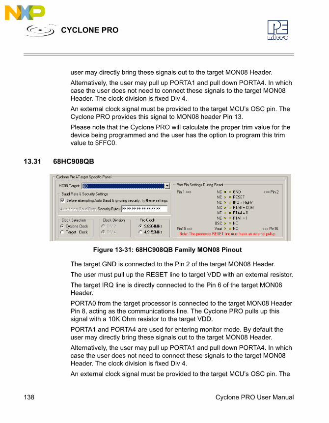
138 Cyclone PRO User Manual
CYCLONE PRO
user may directly bring these signals out to the target MON08 Header.Alternatively, the user may pull up PORTA1 and pull down PORTA4. In which case the user does not need to connect these signals to the target MON08 Header. The clock division is fixed Div 4.An external clock signal must be provided to the target MCU’s OSC pin. The Cyclone PRO provides this signal to MON08 header Pin 13.Please note that the Cyclone PRO will calculate the proper trim value for the device being programmed and the user has the option to program this trim value to $FFC0.
13.31 68HC908QB
Figure 13-31: 68HC908QB Family MON08 Pinout
The target GND is connected to the Pin 2 of the target MON08 Header.The user must pull up the RESET line to target VDD with an external resistor.The target IRQ line is directly connected to the Pin 6 of the target MON08 Header.PORTA0 from the target processor is connected to the target MON08 Header Pin 8, acting as the communications line. The Cyclone PRO pulls up this signal with a 10K Ohm resistor to the target VDD.PORTA1 and PORTA4 are used for entering monitor mode. By default the user may directly bring these signals out to the target MON08 Header.Alternatively, the user may pull up PORTA1 and pull down PORTA4. In which case the user does not need to connect these signals to the target MON08 Header. The clock division is fixed Div 4.An external clock signal must be provided to the target MCU’s OSC pin. The
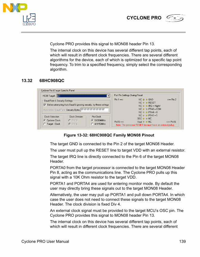
Cyclone PRO User Manual 139
CYCLONE PRO
Cyclone PRO provides this signal to MON08 header Pin 13.The internal clock on this device has several different tap points, each of which will result in different clock frequencies. There are several different algorithms for the device, each of which is optimized for a specific tap point frequency. To trim to a specified frequency, simply select the corresponding algorithm.
13.32 68HC908QC
Figure 13-32: 68HC908QC Family MON08 Pinout
The target GND is connected to the Pin 2 of the target MON08 Header.The user must pull up the RESET line to target VDD with an external resistor.The target IRQ line is directly connected to the Pin 6 of the target MON08 Header.PORTA0 from the target processor is connected to the target MON08 Header Pin 8, acting as the communications line. The Cyclone PRO pulls up this signal with a 10K Ohm resistor to the target VDD.PORTA1 and PORTA4 are used for entering monitor mode. By default the user may directly bring these signals out to the target MON08 Header.Alternatively, the user may pull up PORTA1 and pull down PORTA4. In which case the user does not need to connect these signals to the target MON08 Header. The clock division is fixed Div 4.An external clock signal must be provided to the target MCU’s OSC pin. The Cyclone PRO provides this signal to MON08 header Pin 13.The internal clock on this device has several different tap points, each of which will result in different clock frequencies. There are several different
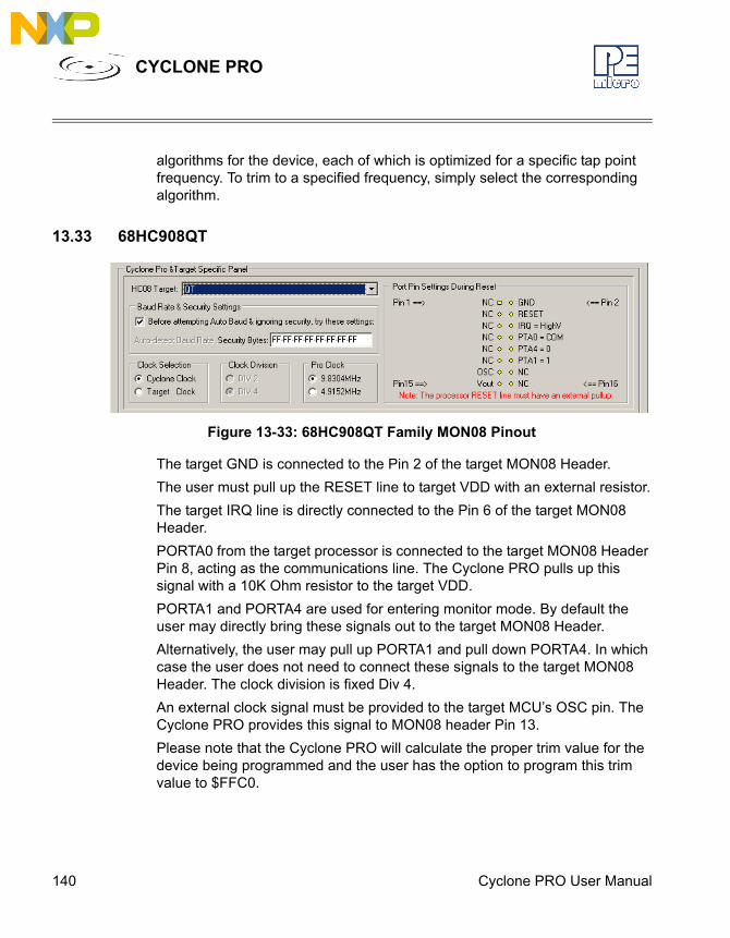
140 Cyclone PRO User Manual
CYCLONE PRO
algorithms for the device, each of which is optimized for a specific tap point frequency. To trim to a specified frequency, simply select the corresponding algorithm.
13.33 68HC908QT
Figure 13-33: 68HC908QT Family MON08 Pinout
The target GND is connected to the Pin 2 of the target MON08 Header.The user must pull up the RESET line to target VDD with an external resistor.The target IRQ line is directly connected to the Pin 6 of the target MON08 Header.PORTA0 from the target processor is connected to the target MON08 Header Pin 8, acting as the communications line. The Cyclone PRO pulls up this signal with a 10K Ohm resistor to the target VDD.PORTA1 and PORTA4 are used for entering monitor mode. By default the user may directly bring these signals out to the target MON08 Header.Alternatively, the user may pull up PORTA1 and pull down PORTA4. In which case the user does not need to connect these signals to the target MON08 Header. The clock division is fixed Div 4.An external clock signal must be provided to the target MCU’s OSC pin. The Cyclone PRO provides this signal to MON08 header Pin 13.Please note that the Cyclone PRO will calculate the proper trim value for the device being programmed and the user has the option to program this trim value to $FFC0.
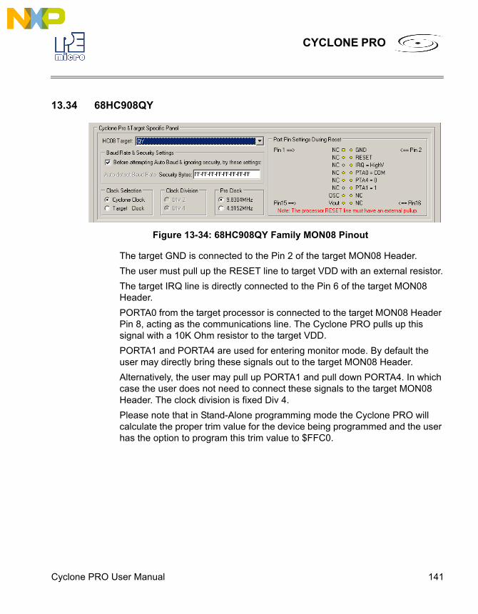
Cyclone PRO User Manual 141
CYCLONE PRO
13.34 68HC908QY
Figure 13-34: 68HC908QY Family MON08 Pinout
The target GND is connected to the Pin 2 of the target MON08 Header.The user must pull up the RESET line to target VDD with an external resistor.The target IRQ line is directly connected to the Pin 6 of the target MON08 Header.PORTA0 from the target processor is connected to the target MON08 Header Pin 8, acting as the communications line. The Cyclone PRO pulls up this signal with a 10K Ohm resistor to the target VDD.PORTA1 and PORTA4 are used for entering monitor mode. By default the user may directly bring these signals out to the target MON08 Header.Alternatively, the user may pull up PORTA1 and pull down PORTA4. In which case the user does not need to connect these signals to the target MON08 Header. The clock division is fixed Div 4.Please note that in Stand-Alone programming mode the Cyclone PRO will calculate the proper trim value for the device being programmed and the user has the option to program this trim value to $FFC0.
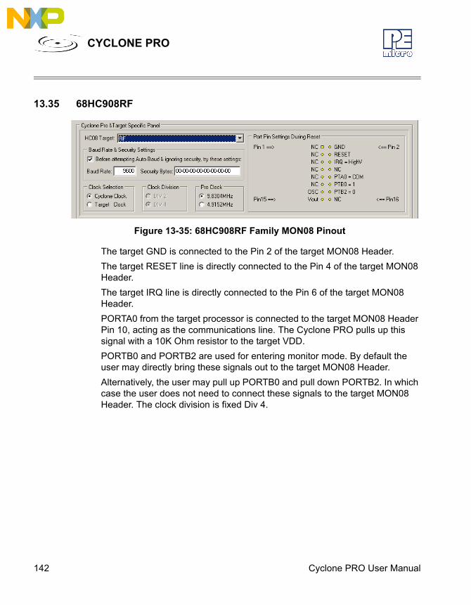
142 Cyclone PRO User Manual
CYCLONE PRO
13.35 68HC908RF
Figure 13-35: 68HC908RF Family MON08 Pinout
The target GND is connected to the Pin 2 of the target MON08 Header.The target RESET line is directly connected to the Pin 4 of the target MON08 Header. The target IRQ line is directly connected to the Pin 6 of the target MON08 Header.PORTA0 from the target processor is connected to the target MON08 Header Pin 10, acting as the communications line. The Cyclone PRO pulls up this signal with a 10K Ohm resistor to the target VDD.PORTB0 and PORTB2 are used for entering monitor mode. By default the user may directly bring these signals out to the target MON08 Header.Alternatively, the user may pull up PORTB0 and pull down PORTB2. In which case the user does not need to connect these signals to the target MON08 Header. The clock division is fixed Div 4.
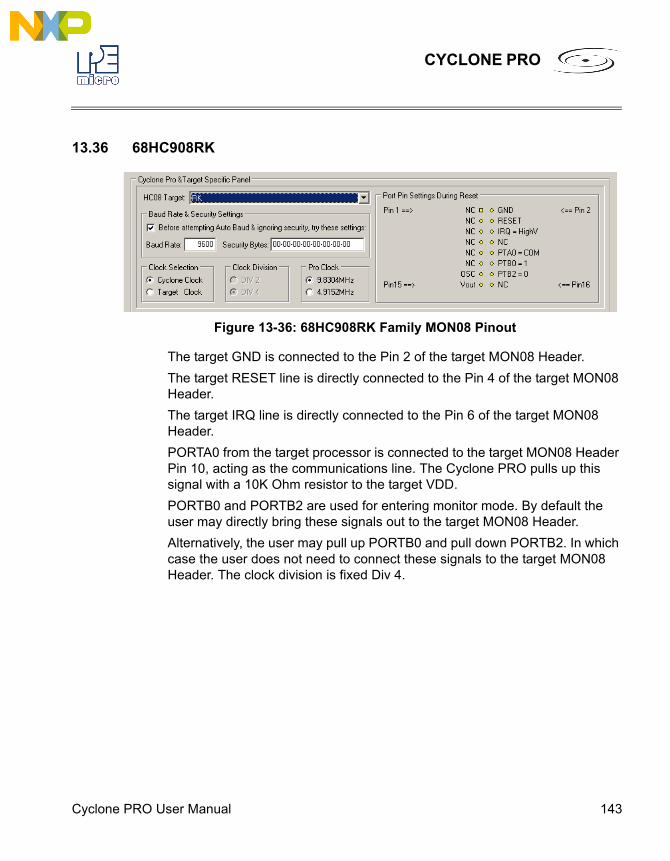
Cyclone PRO User Manual 143
CYCLONE PRO
13.36 68HC908RK
Figure 13-36: 68HC908RK Family MON08 Pinout
The target GND is connected to the Pin 2 of the target MON08 Header.The target RESET line is directly connected to the Pin 4 of the target MON08 Header. The target IRQ line is directly connected to the Pin 6 of the target MON08 Header.PORTA0 from the target processor is connected to the target MON08 Header Pin 10, acting as the communications line. The Cyclone PRO pulls up this signal with a 10K Ohm resistor to the target VDD.PORTB0 and PORTB2 are used for entering monitor mode. By default the user may directly bring these signals out to the target MON08 Header.Alternatively, the user may pull up PORTB0 and pull down PORTB2. In which case the user does not need to connect these signals to the target MON08 Header. The clock division is fixed Div 4.

144 Cyclone PRO User Manual
CYCLONE PRO
13.37 68HC908SR
Figure 13-37: 68HC908SR Family MON08 Pinout
The target GND is connected to the Pin 2 of the target MON08 Header.The target RESET line is directly connected to the Pin 4 of the target MON08 Header. The target IRQ line is directly connected to the Pin 6 of the target MON08 Header.PORTA0 from the target processor is connected to the target MON08 Header Pin 10, acting as the communications line. The Cyclone PRO pulls up this signal with a 10K Ohm resistor to the target VDD.PORTA1, PORTA2 and PORTC1 are used for entering monitor mode. By default the user may directly bring these signals out to the target MON08 Header.Alternatively, the user may pull up PORTA1 and pull down PORTA2, and pull up/down PORTC1 for clock division. In which case the user does not need to connect these signals to the target MON08 Header.
Cyclone PRO User Manual 145
CYCLONE PRO
14 CYCLONE ERROR CODESThe Cyclone will indicate errors using the following codes. Please contact P&E if you are unsure of the specific meaning of an error code.
14.1 Debug Mode Communication Errors$0001: No target response$0002: Invalid target response$0003: Wait for target response canceled$0004: Wait for target response failed$0005: Error detecting communication speed$0006: Failed to unsecure target$0007: Error entering debug mode$0008: Error entering debug mode while target is secured$0009: Error entering debug mode for verification$000A: Error writing a block of data to target$000B: Error enabling or disabling module$000C: Error in performing timing test$000D: MON08 target had an invalid reset
14.2 SAP Image Handling Errors$0011: SAP image ID is greater than total number of images$0012: Error during SAP image validation$0013: SAP operation was not configured$0014: SAP image storage was not initialized$0015: SAP image transfer error, invalid data length$0016: SAP image transfer error, invalid start address$0017: SAP image transfer error while writing to storage$0018: Error writing serial number structure storage$0019: Error writing LCD menu structure storage$001A: Error erasing storage block
146 Cyclone PRO User Manual
CYCLONE PRO
$001B: Error converting downloads counter structure
14.3 SAP Algorithm Header Operation Handling Errors$0061: Undefined header operation, check software and firmware versions
14.4 SAP Operation Errors$0081: SAP operation is not supported, check software and firmware versions$0082: SAP operation error, SAP image contains different target type
14.5 SAP Blank Check Range and Module Errors$1001: Blank check error, algorithm not supported$1002: Blank check error, algorithm not found$1003: Blank check operation failed
14.6 SAP Erase Range and Module Errors$2001: Erase error, algorithm not supported$2002: Erase error, algorithm not found$2003: Erase error, module failed or canceled$2004: Erase error, module failed, target is still secured$2005: Erase error, module not performed, data is preserved
14.7 SAP Program Byte, Word, and Module Errors$3001: Programming algorithm is not supported$3002: Programming algorithm was not found$3003: Program operation failed or canceled$3004: Program operation failed, write protected$300A: Error during reading data block, invalid data length$300B: Error during reading data block, invalid start address$300C: Error during reading data block, no target power$300D: Error during programming data block, invalid data length
Cyclone PRO User Manual 147
CYCLONE PRO
$300E: Error during programming data block, invalid start address$300F: Error during programming data block, no target power
14.8 SAP Verify Checksum Errors$4001: VC command not supported$4002: VC failed, invalid algorithm$4003: VC operation failed or canceled
$4011: VV command not supported$4012: VV failed, invalid algorithm$4013: VV operation failed or canceled
14.9 SAP Verify Range and Module Errors$5003: Verification operation failed or canceled
14.10 SAP User Function Errors$6003: User function failed or canceled
14.11 SAP Trim Errors$7001: Trim operation not supported$7003: No target response$7004: Trim write error, trim value not set$7007: Trim write error, trim value failed$7008: Trim read error, trim value failed$7009: Trim value invalid, value is blank or zero
14.12 Unrecoverable Fatal Errors$8001: Fatal Error, please contact P&E$8002: Fatal Error, please contact P&E$8003: Fatal Error, please contact P&E
148 Cyclone PRO User Manual
CYCLONE PRO
$8004: Fatal Error, please contact P&E$8005: Fatal Error, please contact P&E$8006: Fatal Error, please contact P&E$8007: Fatal Error, please contact P&E$8008: Fatal Error, please contact P&E$8009: Fatal Error, please contact P&E$800A: Fatal Error, please contact P&E$800B: Fatal Error, please contact P&E$800C: Fatal Error, please contact P&E$800D: Fatal Error, please contact P&E$800E: Fatal Error, please contact P&E$800F: Fatal Error, please contact P&E$8010: Fatal Error, please contact P&E$8011: Fatal Error, please contact P&E$8012: Fatal Error, please contact P&E$8013: Fatal Error, please contact P&E$8014: Fatal Error, please contact P&E$8015: Fatal Error, please contact P&E$8016: Fatal Error, please contact P&E$8017: Fatal Error, please contact P&E$8018: Fatal Error, please contact P&E$8019: Fatal Error, please contact P&E$8020: Fatal Error, please contact P&E$8021: Fatal Error, please contact P&E
14.13 External Memory Errors$A001: Error writing to external memory$A002: Error formatting the external memory$A003: External memory was disconnected during use$A004: External memory has unsupported format
Cyclone PRO User Manual 149
CYCLONE PRO
$A005: External memory has corrupted data$A006: External memory disk error$A007: Failed during internal image verification$A008: Failed during external image verification$A009: Error while reading external memory for image pointer
14.14 Serial Number Errors$B001: Error erasing serial number storage$B002: Error writing serial number$B003: Total number of Serial Number Structures is over limit of 254.$B004: Error converting serial number structure$B005: Error updating serial number
14.15 Successful Download Counter Errors$C001: Error erasing download counter storage$C002: Error writing download counter$C003: Total number of download counter is over limit of 254.$C004: Error converting download counter structure

150 Cyclone PRO User Manual
CYCLONE PRO

Recommended