University of Wisconsin - Madison
Current Lead Design
US Particle Accelerator SchoolJune 21-25, 2004

University of Wisconsin - Madison
Current Lead Design• What is a current lead and what are the
design challenges?• Design goal - minimize cryogenic impact• Configurations• What do you expect?• Designing conventional leads
– Conduction cooled– Vapor cooled– Forced flow cooled
• Designing HTS (hybrid) leads– Cooling options– Additional factors to consider
University of Wisconsin - Madison
Purpose, Design Challenge• Purpose: Communicate electric
power from room temperature tocryogenic coils, magnets,transmission lines, or devices.
• Design challenge:– Cryogenic heat load due to:
• Heat conduction
• Heat generation (I2R)
– Reducing conduction (reduce area,increase length, reduce k) increasesheat generation
– Reducing heat generation(increase area, decrease length,reduce ρ) increases conduction
– Optimization required
AMI 75 kAConventional, heliumvapor-cooled leads
75 kA leads atzero current
University of Wisconsin - Madison
Goal: Minimize Impact on Cryogenic System
• Open systems: reduce cryogen boil-off• Benchmark: 1.1 W/kA-lead = 3 liter/hr-kA-pair
for conventional helium vapor cooled leads
• Closed cycle refrigerator: improve performance• Reduce the required electrical power to refrigerate vapor
exiting warm end of leads:
≈ 7 kW electrical power for pair of 1 kA conventional leads
• Improve reliability by using a cryocooler to re-condense vaporat 4.2 K
• Replacing conventional 5 kA leads with HTS versionsprovides Fermilab Tevatron excess refrigeration to reducemagnet temperature from 4.2 K to 3.5 K.
University of Wisconsin - Madison
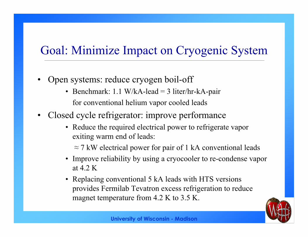
Configurations
• Conventional– Conduction cooled
– Vapor cooled
– Forced-flow cooled
• HTS - hybrid– Conduction cooled
– Vapor cooled
– Forced-flow cooled
Tc
Th
Th
Tc
Tint
cryocooler
1st stage
2nd stage
Cu
HTS
Lead
nitrogeninhelium
out
University of Wisconsin - Madison
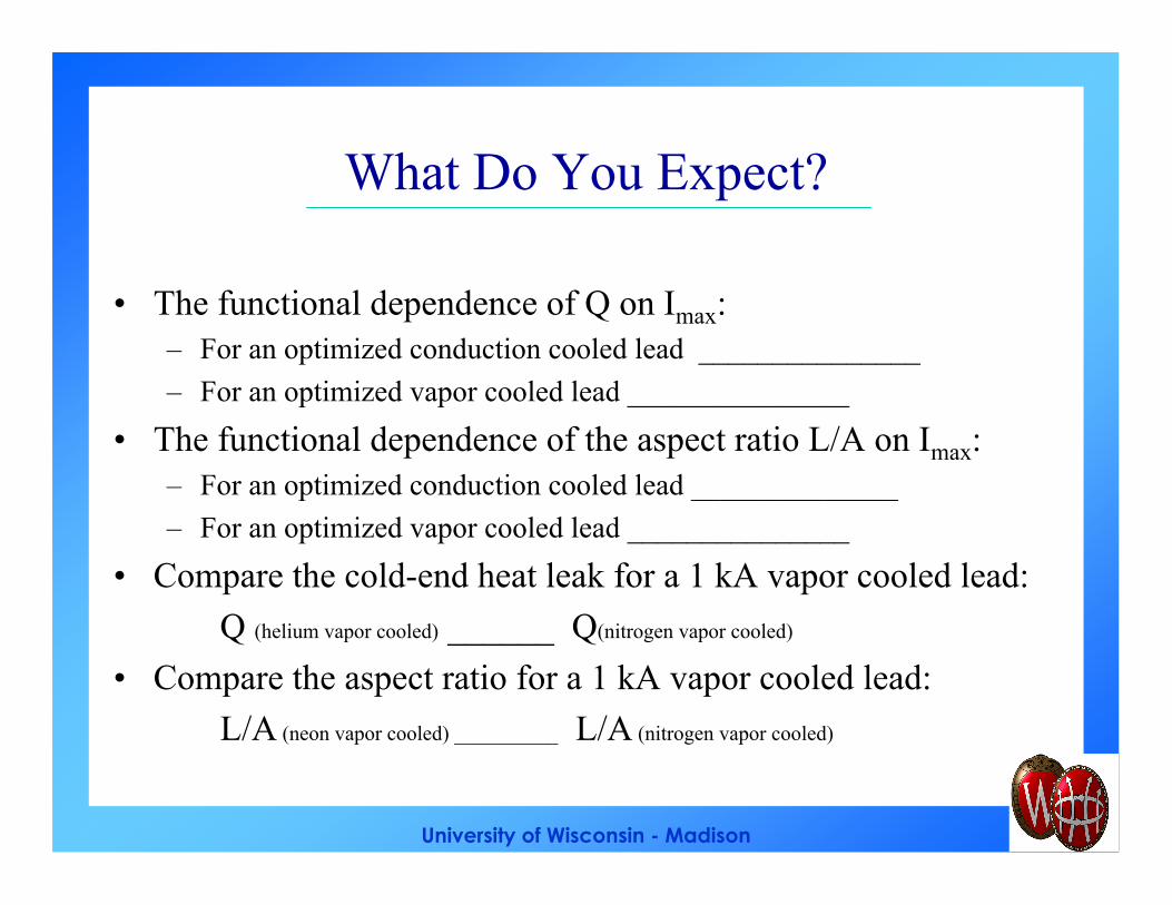
What Do You Expect?
• The functional dependence of Q on Imax:– For an optimized conduction cooled lead _______________
– For an optimized vapor cooled lead _______________
• The functional dependence of the aspect ratio L/A on Imax:– For an optimized conduction cooled lead ______________
– For an optimized vapor cooled lead _______________
• Compare the cold-end heat leak for a 1 kA vapor cooled lead:
Q (helium vapor cooled) ______ Q(nitrogen vapor cooled)
• Compare the aspect ratio for a 1 kA vapor cooled lead:
L/A (neon vapor cooled) __________ L/A (nitrogen vapor cooled)
University of Wisconsin - Madison
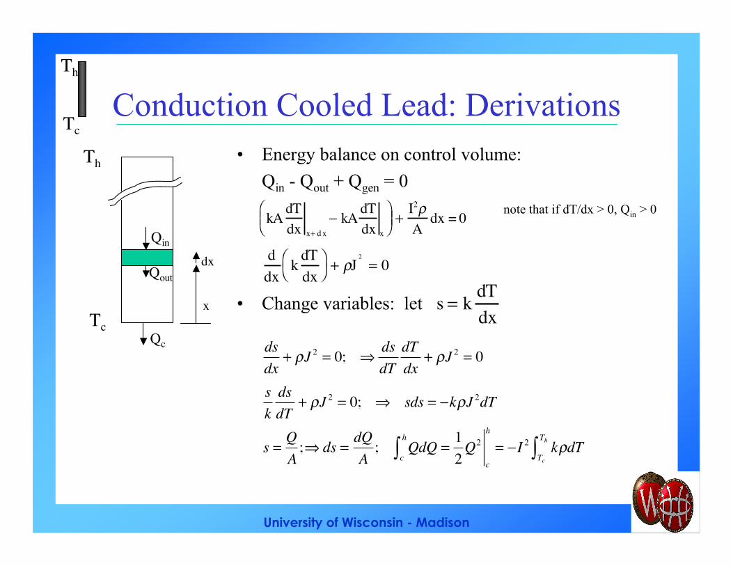
Conduction Cooled Lead: Derivations• Energy balance on control volume:
Qin - Qout + Qgen = 0
note that if dT/dx > 0, Qin > 0
• Change variables: let
Th
Tc
x
Qin
Qoutdx
Qc
kA dTdx x+ d x
− kA dTdx x
+
I2ρA
dx = 0
s = k dTdx
ddx
k dTdx
+ ρJ
2
= 0
Tc
Th
dsdx
+ ρJ 2 = 0; ⇒dsdT
dTdx
+ ρJ 2 = 0
sk
dsdT
+ ρJ 2 = 0; ⇒ sds = −kρJ 2dT
s =QA
;⇒ ds =dQA
; QdQ =12
Q2
c
h
= −I 2 kρdTTc
Th∫c
h
∫
University of Wisconsin - Madison
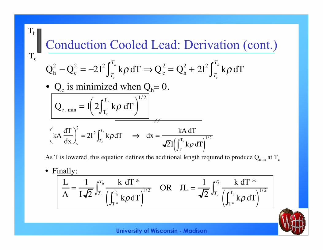
Conduction Cooled Lead: Derivation (cont.)
Qh2 − Qc
2 = −2I2 kρ dTTc
Th
∫ ⇒ Q c2 = Qh
2 + 2I2 kρ dTTc
Th
∫• Qc is minimized when Qh= 0.
kA dTdx
c
2
= 2I2 kρ dTTc
Th
∫ ⇒ dx =kA dT
2I kρ dTT
Th
∫( )1/ 2
As T is lowered, this equation defines the additional length required to produce Qmin at Tc
• Finally:LA
=1
I 2k dT *
kρ dTT*
Th
∫( )1/ 2Tc
Th
∫ OR JL = 12
k dT *
kρ dTT*
Th
∫( )1/ 2Tc
Th
∫
Qc, min = I 2 kρ dTTc
Th
∫
1/ 2
Tc
Th
University of Wisconsin - Madison
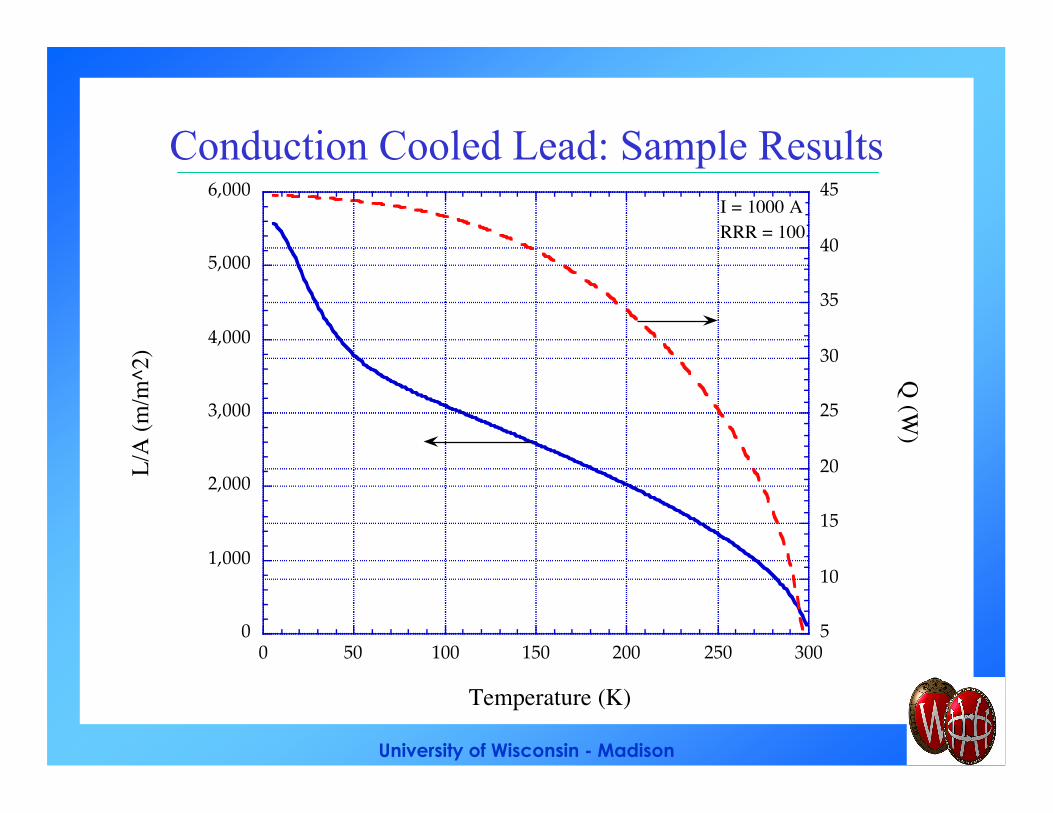
Conduction Cooled Lead: Sample Results
0
1,000
2,000
3,000
4,000
5,000
6,000
5
10
15
20
25
30
35
40
45
0 50 100 150 200 250 300
L/A
(m/m
^2)
Q (W
)
Temperature (K)
I = 1000 ARRR = 100
University of Wisconsin - Madison
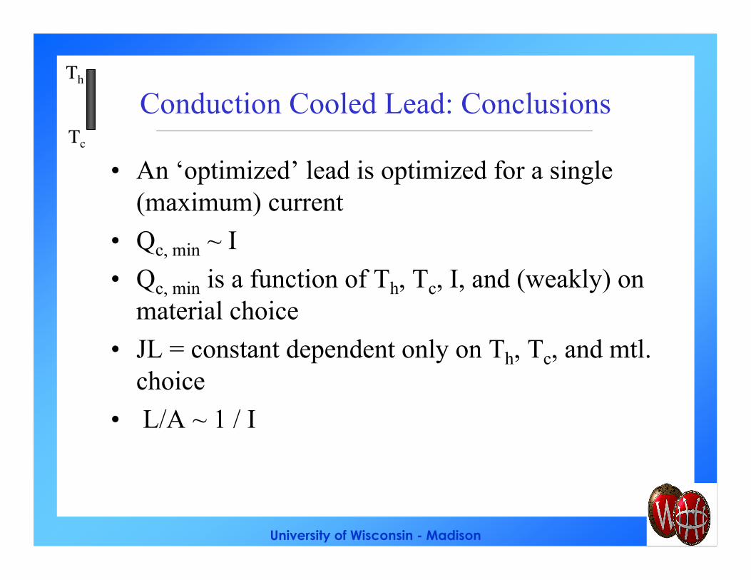
Conduction Cooled Lead: Conclusions
• An ‘optimized’ lead is optimized for a single(maximum) current
• Qc, min ~ I
• Qc, min is a function of Th, Tc, I, and (weakly) onmaterial choice
• JL = constant dependent only on Th, Tc, and mtl.choice
• L/A ~ 1 / I
Tc
Th
University of Wisconsin - Madison
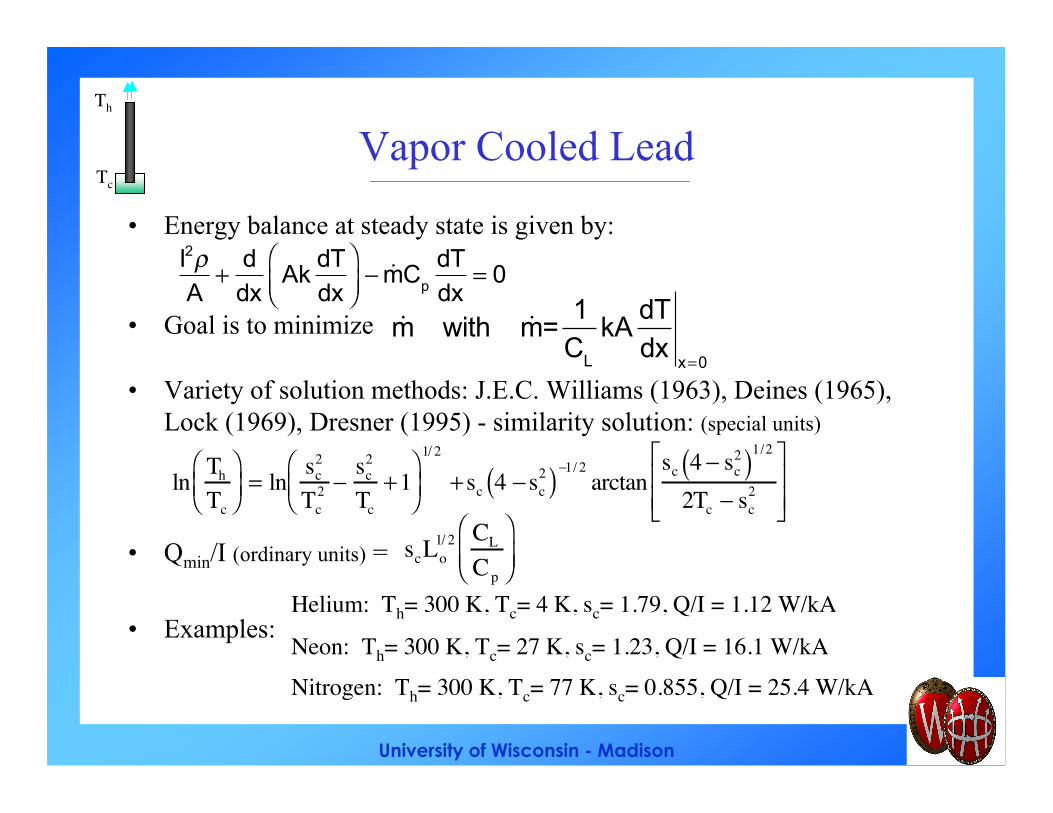
Vapor Cooled Lead
• Energy balance at steady state is given by:
• Goal is to minimize
• Variety of solution methods: J.E.C. Williams (1963), Deines (1965),Lock (1969), Dresner (1995) - similarity solution: (special units)
• Qmin/I (ordinary units) =
• Examples:
Th
Tc
I2ρA
+ ddx
AkdTdx
− &mCp
dTdx
= 0
&m with &m=
1C
L
kAdTdx
x =0
ln Th
Tc
= ln sc
2
Tc2 −
sc2
Tc+ 1
1/ 2
+ sc 4 − sc2( ) −1/ 2
arctansc 4 − sc
2( )1/2
2Tc − sc2
scLo1/ 2 CL
Cp
Helium: Th= 300 K, Tc= 4 K, sc= 1.79, Q/I = 1.12 W/kA
Nitrogen: Th= 300 K, Tc= 77 K, sc= 0.855, Q/I = 25.4 W/kANeon: Th= 300 K, Tc= 27 K, sc= 1.23, Q/I = 16.1 W/kA
University of Wisconsin - Madison
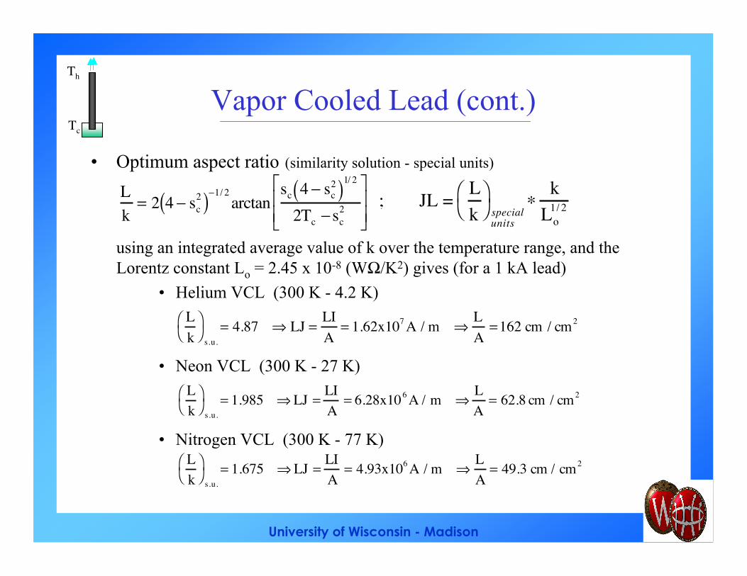
Vapor Cooled Lead (cont.)
• Optimum aspect ratio (similarity solution - special units)
using an integrated average value of k over the temperature range, and theLorentz constant Lo = 2.45 x 10⁻⁸ (WΩ/K2) gives (for a 1 kA lead)
• Helium VCL (300 K - 4.2 K)
• Neon VCL (300 K - 27 K)
• Nitrogen VCL (300 K - 77 K)
Th
Tc
Lk
= 2 4 − sc2( )−1/ 2
arctansc 4 − sc
2( )1/ 2
2Tc − sc2
; JL = Lk
special
units
∗k
Lo1/ 2
Lk
s.u.= 4.87 ⇒ LJ =
LIA
= 1.62x10⁷ A / m ⇒LA
= 162 cm / cm2
Lk
s.u.= 1.985 ⇒ LJ =
LIA
= 6.28x10⁶ A / m ⇒LA
= 62.8 cm / cm2
Lk
s.u.= 1.675 ⇒ LJ =
LIA
= 4.93x10⁶ A / m ⇒LA
= 49.3 cm / cm2
University of Wisconsin - Madison
Vapor Cooled Lead - Conclusions
• Minimum heat leak:– As with conduction cooled leads, Qmin ~ I
– Dependence of Qmin on coolant is dominated by (CL / Cp)
• Optimized aspect ratio:– L/Aopt ~ 1/I smaller current → larger aspect ratio
– L/Aopt dependence on coolant: colder range → larger aspect ratio
University of Wisconsin - Madison
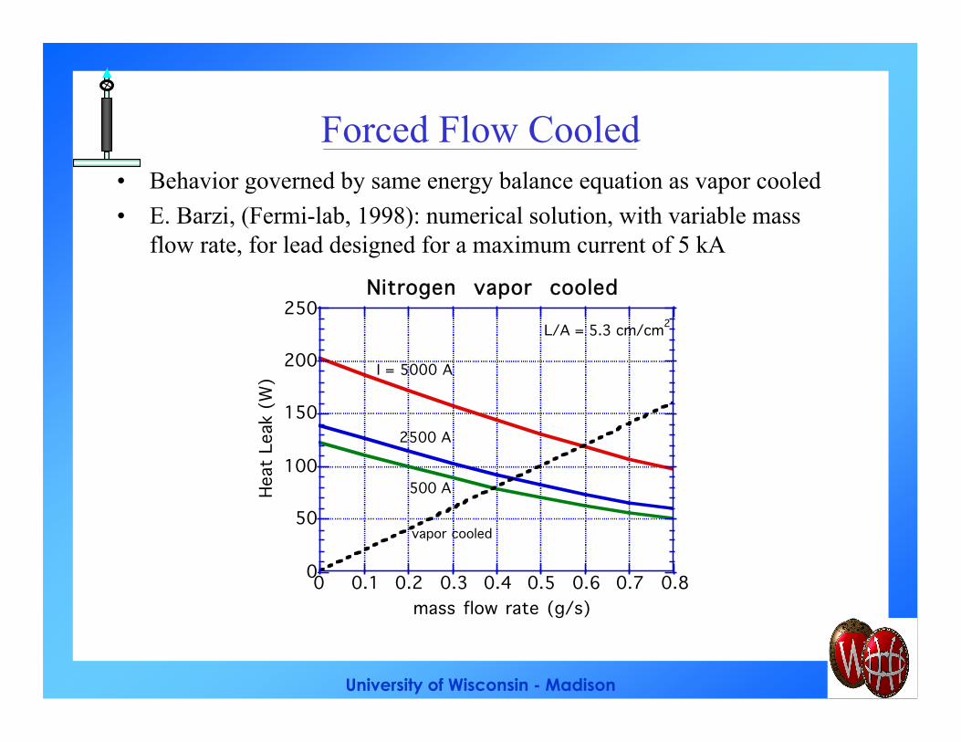
Forced Flow Cooled• Behavior governed by same energy balance equation as vapor cooled
• E. Barzi, (Fermi-lab, 1998): numerical solution, with variable massflow rate, for lead designed for a maximum current of 5 kA
0
50
100
150
200
250
0 0.1 0.2 0.3 0.4 0.5 0.6 0.7 0.8
Nitrogen vapor cooledHe
at L
eak
(W)
mass flow rate (g/s)
L/A = 5.3 cm/cm2
I = 5000 A
2500 A
500 A
vapor cooled
University of Wisconsin - Madison
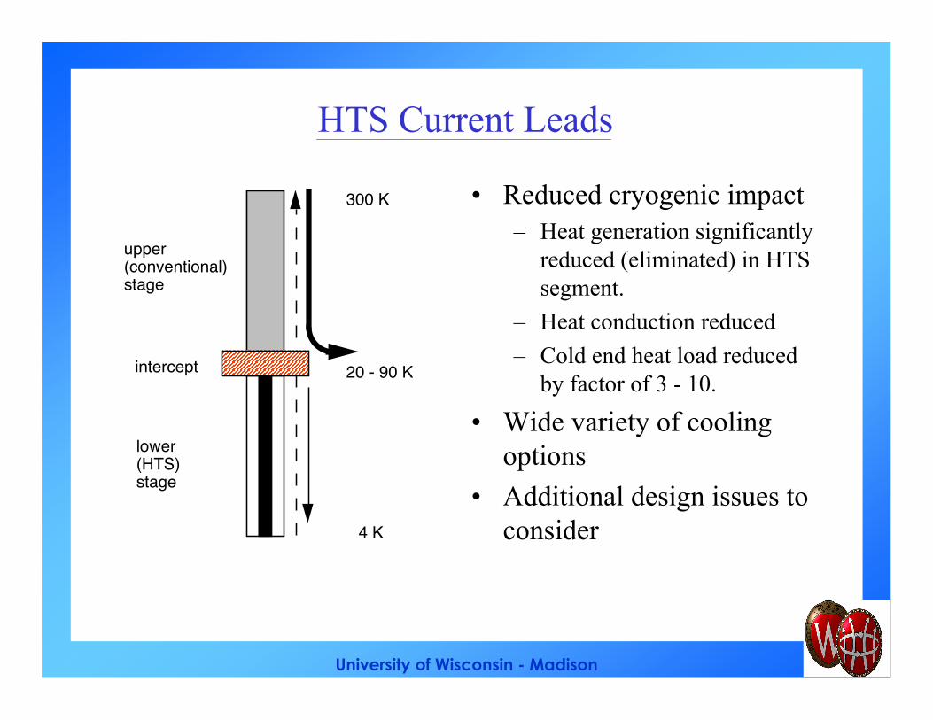
HTS Current Leads
• Reduced cryogenic impact– Heat generation significantly
reduced (eliminated) in HTSsegment.
– Heat conduction reduced
– Cold end heat load reducedby factor of 3 - 10.
• Wide variety of coolingoptions
• Additional design issues toconsider
upper(conventional)stage
intercept
lower(HTS)stage
300 K
20 - 90 K
4 K
University of Wisconsin - Madison
Cooling Options for HTS Leads
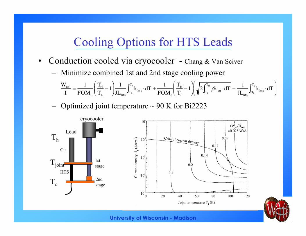
• Conduction cooled via cryocooler - Chang & Van Sciver
– Minimize combined 1st and 2nd stage cooling power
– Optimized joint temperature ~ 90 K for Bi2223
Wref
I=
1FOML
TH
TL− 1
1JLhts
khts ⋅ dTTL
TJ
∫ +1
FOMJ
TH
TJ− 1
2 ρkcu ⋅dT
TJ
TH
∫ −1
JLhtskhts ⋅ dT
TL
TJ
∫
Th
Tc
Tjoint
cryocooler
1st stage
2nd stage
Cu
HTS
Lead
University of Wisconsin - Madison
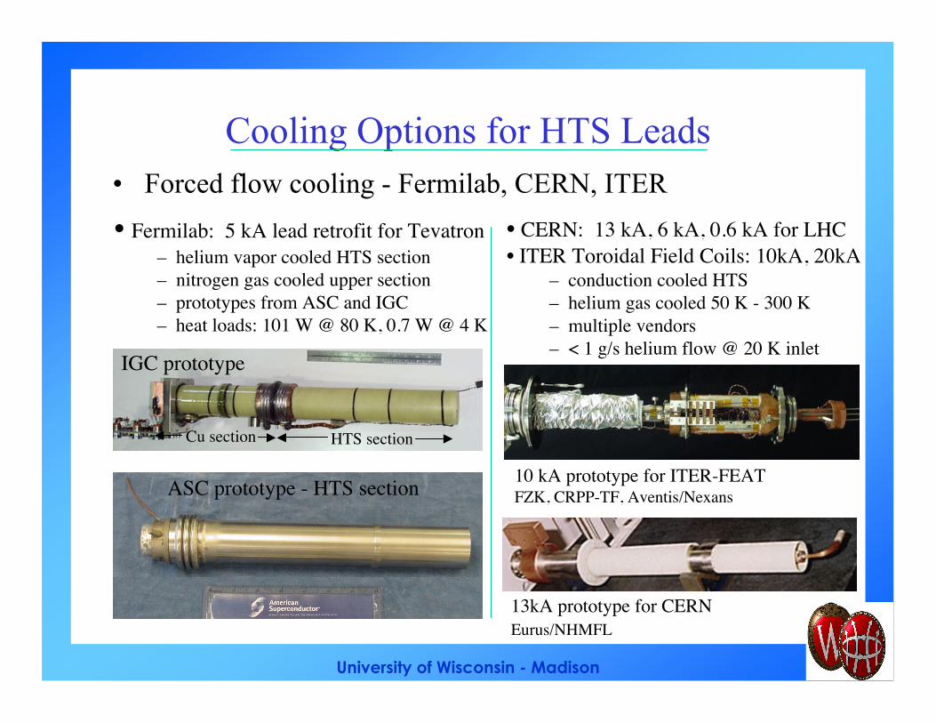
Cooling Options for HTS Leads• Forced flow cooling - Fermilab, CERN, ITER
• Fermilab: 5 kA lead retrofit for Tevatron– helium vapor cooled HTS section– nitrogen gas cooled upper section– prototypes from ASC and IGC– heat loads: 101 W @ 80 K, 0.7 W @ 4 K
HTS sectionCu section
IGC prototype
ASC prototype - HTS section
• CERN: 13 kA, 6 kA, 0.6 kA for LHC• ITER Toroidal Field Coils: 10kA, 20kA
– conduction cooled HTS– helium gas cooled 50 K - 300 K– multiple vendors– < 1 g/s helium flow @ 20 K inlet
13kA prototype for CERNEurus/NHMFL
10 kA prototype for ITER-FEAT FZK, CRPP-TF, Aventis/Nexans
University of Wisconsin - Madison
Cooling Options for HTS Leads
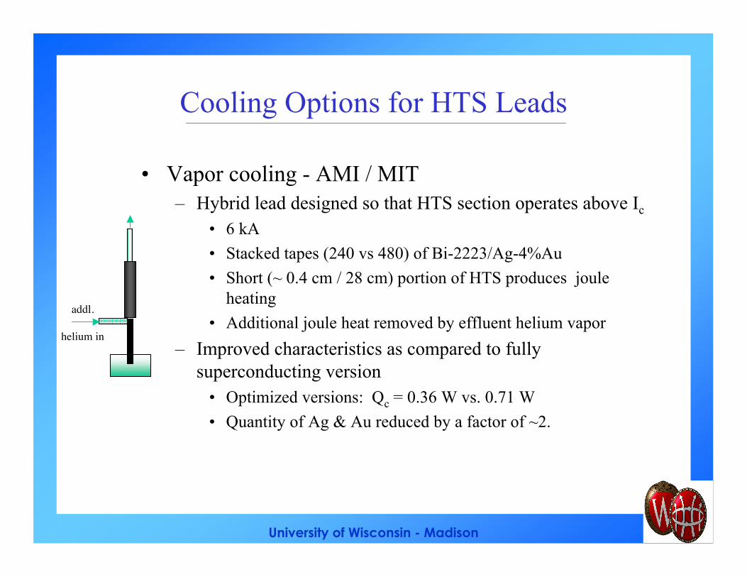
• Vapor cooling - AMI / MIT– Hybrid lead designed so that HTS section operates above Ic
• 6 kA
• Stacked tapes (240 vs 480) of Bi-2223/Ag-4%Au
• Short (~ 0.4 cm / 28 cm) portion of HTS produces jouleheating
• Additional joule heat removed by effluent helium vapor
– Improved characteristics as compared to fullysuperconducting version
• Optimized versions: Qc = 0.36 W vs. 0.71 W
• Quantity of Ag & Au reduced by a factor of ~2.
addl.
helium in
University of Wisconsin - Madison
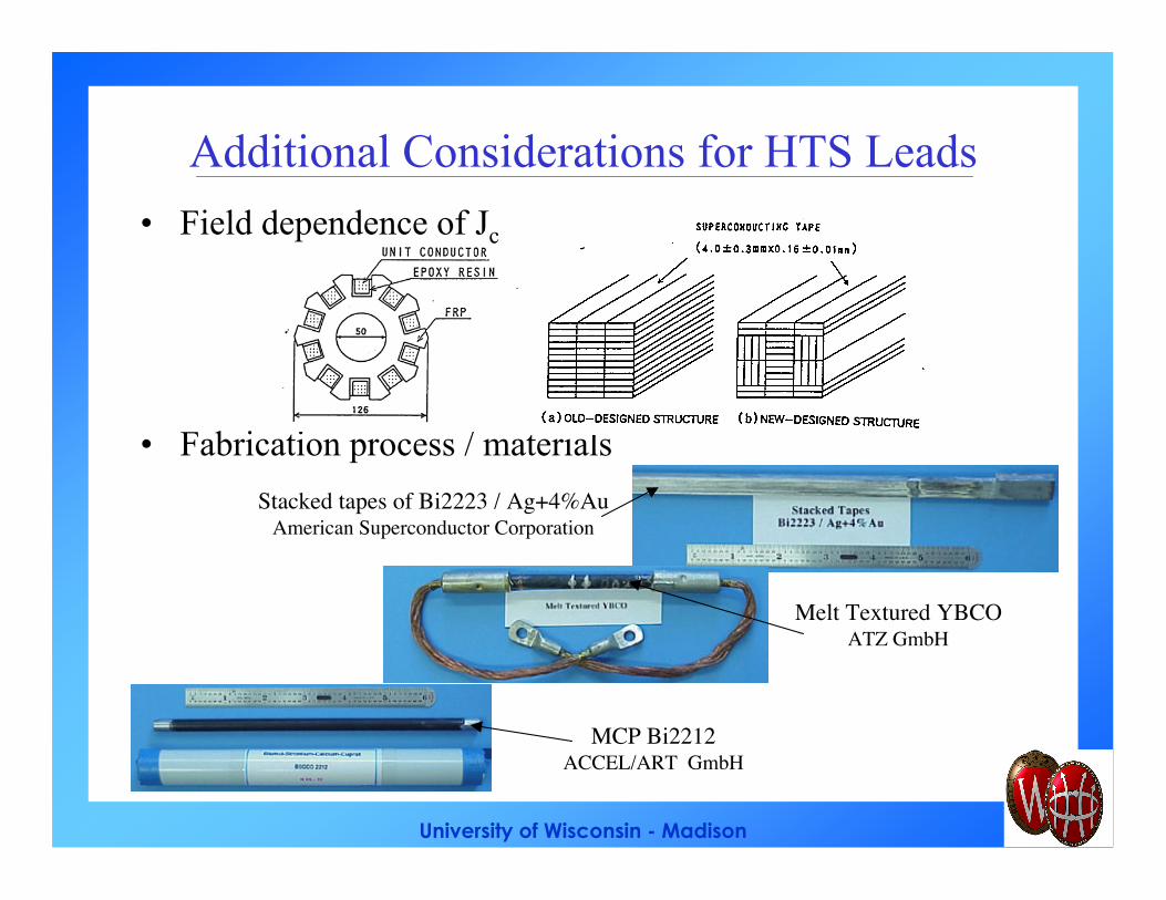
Additional Considerations for HTS Leads
• Field dependence of Jc
• Fabrication process / materials
Stacked tapes of Bi2223 / Ag+4%AuAmerican Superconductor Corporation
Melt Textured YBCOATZ GmbH
MCP Bi2212ACCEL/ART GmbH
University of Wisconsin - Madison
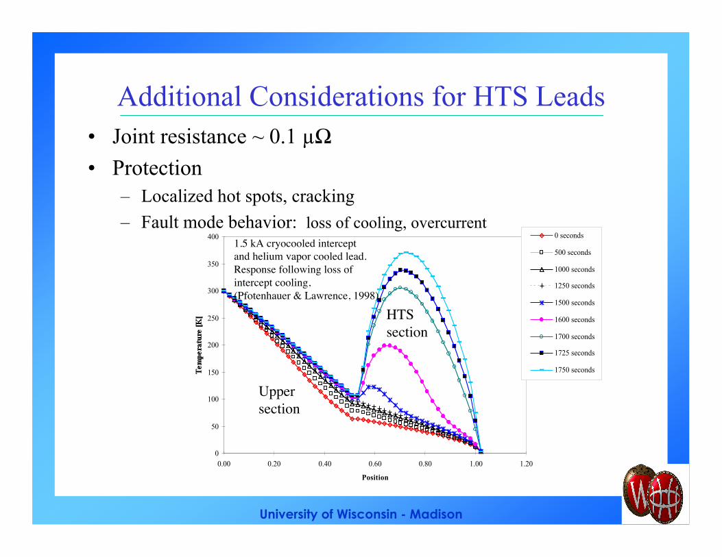
Additional Considerations for HTS Leads• Joint resistance ~ 0.1 µΩ
• Protection– Localized hot spots, cracking
– Fault mode behavior: loss of cooling, overcurrent
0
50
100
150
200
250
300
350
400
0.00 0.20 0.40 0.60 0.80 1.00 1.20
Position
0 seconds
500 seconds
1000 seconds
1250 seconds
1500 seconds
1600 seconds
1700 seconds
1725 seconds
1750 seconds
Uppersection
HTSsection
1.5 kA cryocooled interceptand helium vapor cooled lead.Response following loss ofintercept cooling,(Pfotenhauer & Lawrence, 1998)
University of Wisconsin - Madison
References• S. Deiness, “The Production and Optimization of
High Current Leads,” Cryogenics, vol. 5, pp. 269-271, October 1965
• J.E.C. Williams, “Counterflow Current Leads forCryogenic Applications,” Cryogenics, vol. 3, pp.234-238, December 1963.
• Yu.L. Buyanov, “Current Leads for use inCryogenic Devices. Principle of Design andFormulae for Design Calculations,” Cryogenics,vol. 25, pp. 94-110, February 1985.
• J.R. Hull, “High Temperature SuperconductingCurrent Leads,” IEEE Trans. on AppliedSuperconductivity, vol. 3 (1), pp. 869 - 875, 1992.
• L. Dresner, Stability of Superconductors, Plenum,1995, pp. 190-197.
• R. Wesche and A.M. Fuchs, “Design ofSuperconducting Current Leads,” Cryogenics, vol.34, pp. 145-154, February 1994.
• E. Barzi, “Gas/Vapour-Cooled Binary CurrentLeads: Copper Part,” Fermilab internal reportnumber TD-98-026, March 1998.
• H.M. Chang and S.W. Van Sciver,“Thermodynamic Optimization of ConductionCooled HTS Current Leads,” Cryogenics, vol. 38(7), pp. 729-736, July 1998.
• T.M. Taylor, “HTS Current Leads for the LHC,”IEEE Trans. on Applied Superconductivity, vol. 9(2), pp. 412 - 415, June 1999.
• J.M. Pfotenhauer and J.W. Lawrence,“Characterizing Thermal Runaway in HTS CurrentLeads,” IEEE Trans. on Applied Superconductivity,vol. 9 (2), pp. 424 - 427, June 1999.
• A. Hobl et.al., “HTc Current Leads in CommercialMagnet Systems Applying Bi 2212 MCP BSCCOMaterial,” IEEE Trans. on Appl. Superconductivity,vol. 9 (2), pp. 495-498, June 1999.
• R. Heller et.al., “Status of the DevelopmentProgram of a 60 kA HTSC Current Lead for theITER Toroidal Field Coils,” IEEE Trans. onApplied Superconductivity, vol. 9 (2), pp. 507 -510, June 1999.
• G. Citver, S. Feher, T.J. Peterson, C.D. Sylvester,“Thermal Tests of 6 kA HTS Current Leads for theTevatron,” Advances in Cryogenic Engineering,vol. 45, pp. 1549 - 1564 2000.
• Y. Iwasa and H. Lee, “High TemperatureSuperconducting Current Lead IncorporatingOperation in the Current-sharing Mode,”Cryogenics vol. 40 pp. 209-219, 2000.
Recommended