Cronfa - Swansea University Open Access Repository
_____________________________________________________________
This is an author produced version of a paper published in :
Metallurgical and Materials Transactions B
Cronfa URL for this paper:
http://cronfa.swan.ac.uk/Record/cronfa10558
_____________________________________________________________
Paper:
Whittaker, M. (2012). Microstructural Characterization of a Prototype Titanium Alloy Structure Processed via Direct
Laser Deposition (DLD). Metallurgical and Materials Transactions B, 43(2)
http://dx.doi.org/10.1007/s11663-011-9599-x
_____________________________________________________________ This article is brought to you by Swansea University. Any person downloading material is agreeing to abide by the
terms of the repository licence. Authors are personally responsible for adhering to publisher restrictions or conditions.
When uploading content they are required to comply with their publisher agreement and the SHERPA RoMEO
database to judge whether or not it is copyright safe to add this version of the paper to this repository.
http://www.swansea.ac.uk/iss/researchsupport/cronfa-support/
Microstructural characterisation of a prototype titanium alloy structure
processed via Direct Laser Deposition (DLD)
D. Clark#, M.T. Whittaker * and M.R. Bache*
# Rolls-Royce plc, P.O. Box 31, Derby, UK, DE24 8BJ
* Materials Research Centre, School of Engineering, Swansea University, Singleton
Park, Swansea, UK, SA2 8PP
Abstract
Processing trials have produced a three dimensional, thin-walled structure of
representative aerospace component geometry, fabricated directly by laser melting of
Ti 6Al4V powder. This additive-built form has been subjected to metallographic
characterisation. The fabrication technique is evaluated as an economic, commercial
process capable of adding features such as bosses or flanges as a hybrid-
manufacturing route for existing forms of gas turbine components.
Samples were extracted from six locations with different wall thickness, varying form
and intersecting ligament geometries. A fine scale Widmanstätten colony
microstructure was consistent throughout the structure within grains elongated
parallel to the axis of epitaxy. Evidence of limited grain boundary α was detected,
however, this was never continuous around individual grains. A moderate Burgers
texture was measured employing EBSD, consistent with melt / cast titanium alloy
forms cooling through the β transus.
Introduction
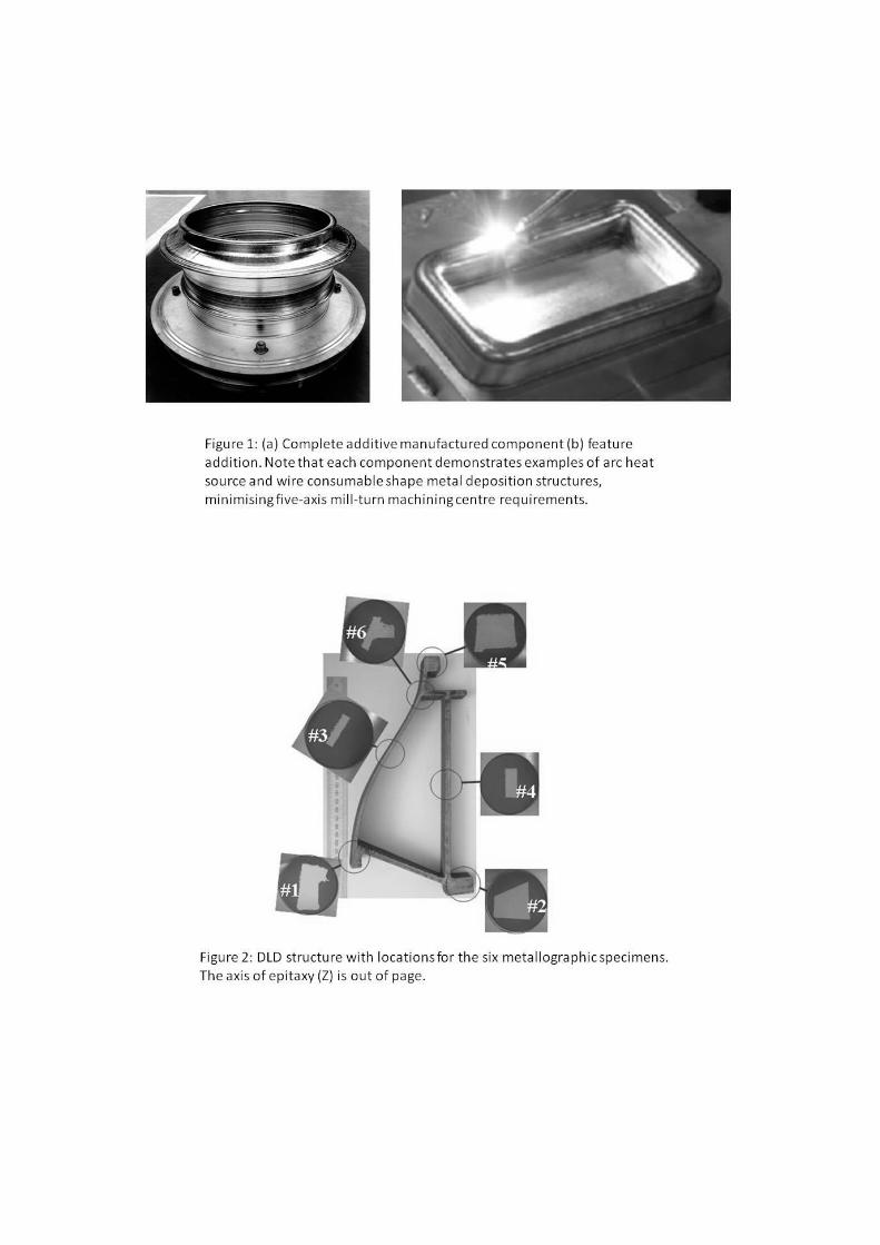
The high strength to weight ratio and damage tolerance characteristics of titanium
alloys makes these systems attractive for applications such as large structural casing
components, struts and vanes in the compressor sections of gas turbine engines,
Figure 1. Such structures typically have integrated functionality, combining the needs
to resist pressure loading with the requirement to provide local stiffening for
attachment features whilst minimising excess mass. Creating load carrying sections
as webs, flanges and hollow features is possible using subtractive manufacture and
fabrication or via casting with the use of cores, however, these methods show
increasing cost and technological complexity[1]
as the complexity of the geometry
increases together with the requirements for precision on fine length scales. Using an
additive manufacturing technique changes the balance point of these relationships[2]
,
allowing potentially greater design sophistication[3]
in shorter lead-time components.
Moreover, the flexibility of the approach allows opportunities for economic savings
through reduced processing operations, reduced component count or the use of
simpler, lower cost preforms. In particular, additive processing can reduce the number
of joints within complex structures. This can enable designs with increased stiffness
while reducing the associated mass and feature cost of the joint regions.
Near net shape fabrication is a desirable outcome both through the substantial
reduction of time spent in material removal, especially for complex forms, relative to
machining intensive routes and also through the efficiency in material usage,
particularly for high cost alloys. Castings can offer similar opportunities, although
still requiring mould-making and core removal. However, key differences are in the
requirements for the development of associated tooling such as patterns and metal
running systems, particularly for intricate forms.
There are now many different types of additive process employing a variety of
consumable and fusion techniques which display varying characteristics with respect
to forming complexity, surface control, volumetric deposition rate, heat accumulation
and feature resolution scale. Zheng et al[4]
conducted a comparative evaluation of
microstructures resulting from welding using tungsten inert gas (TIG), plasma and
laser welded Ti 6Al 4V. All the processes produced weld beads without visual
evidence of oxygen contamination when using local shielding arrangements. The
titanium alloy showed differences in microstructure and hardness when welded using
different processes. For these welding samples, a correlation between processing
parameters and microstructure was established. This study showed that for laser
welds, the grain size increased as the welding speed decreased. This is believed to
correspond to residence time in the thermal region allowing grain coarsening for the
heat affected zone, potentially combined with a reduced driving force for grain
nucleation due to the reduced thermal gradients. Laser deposition is compared in
terms of heat input into the workpiece with TIG and plasma powder transferred arc
(PTA) welding by Nowotny et al[5]
.
Due to the need to form narrow walls with sharp corners a blown powder deposition
process was selected in preference to wire or tape based processes, which offer
advantages in terms of material utilisation. Kobryn and Semiatin[6]
, gave an overview
of laser additive manufacture for Ti 6Al 4V, showing that laser processes together
with powder could yield comparative deposition rates to wire based processes.
However, it is noted that deposition rate may be considered as the product of the
voxel or bead cross-section and the process speed. The former term dictates the
thermal momentum of the process in terms of the quantity of molten metal locally,
which has substantial bearing on solidification rate, temperature gradients and
associated distortions. The travel speed is typically limited by the need to maintain
processing consistency particularly with direction changes, typically balancing
machine manipulation kinematics with energy input rates due to the ballistic
complexity in rapidly metering the consumable input rate without feed forward
controls[7]
. To allow fine feature resolution in blown powder systems, there are
practical limitations to travel speed and pool size. With reducing pool dimension[8]
,
the consumable input characteristics tend to scale accordingly[9-12]
in ensuring stable
melting. This scaling effect has practical and economic consequences through the
increasing degree of processing involved in creating and precisely positioning finer
scale wire consumables. For this reason powder consumables with diameters
substantially below those available for drawn welding wires are favourable. Powder is
not without drawbacks, however, for example through the need to maintain a
coincident locus of adequate powder flux with a fine scale melt pool, unfused powder
represents not only reduced yield, but also risks partially melted powder particles
forming adherent agglomerates thus compromising surface finish and ultimately
structural integrity. There are various techniques that have been proposed for
controlling this[13]
including further reducing travel speed, remelting passes which
may be oblique to a surface and the use of secondary heat sources. Alternatively, the
surface may be smoothed by mechanical or electro-chemical means.
In creating a complex geometry, invariably there will be regions of varying thermal
accumulation, for example different cross-sections providing varying radiative and
convective cooling, bead start and stop points. For features with high curvature,
internal and external edges will exhibit differences in surface processing rates for the
same angular velocity. Due to the different radii, fine scale features depending on
energy flux per unit length can be subject to variation. As Ti 6Al 4V develops a two
phase microstructure the precise form of this structure will be very sensitive to
temperature variations through the beta transus. Due to the comparatively small
molten volumes at any point in time relative to the solidified form, the heat
dissipation rate down thermal gradients close to the pool is typically rapid. The
evolving microstructure will continue to be governed by the conditions in the adjacent
solidified material and the spatial / temporal rate and duration of revisitations of a
given volume by the molten region. A component exhibiting varying processing
conditions at different locations throughout the geometry could risk significant
microstructural and hence mechanical inhomogeneity. To accurately predict
component performance under multi-axial service loading it is necessary to know any
orientation effect on mechanical response. This is simplified if the metal structure can
be controlled through process design to minimise crystallographic texture. Such
texture could arise in the prior beta grains from epitaxial grain growth in the pool or
competitive grain growth between layers along thermal gradients. Kobryn and
Semiatin[6]
studied the deposition of this alloy on a -annealed substrate. They
reported that the texture within the deposit partially corresponded to that of the
substrate whilst also including a solidification induced <100> fibre[14]
. The
solidification texture could be expected to compete with the substrate texture with
progressive height from the substrate. This would have implications for hybrid as
opposed to complete additive fabrication. However this can also be interpreted that
each layer and individual bead has the potential to reorient texture if toolpaths and
deposition strategies are appropriately designed. Microstructural orientation could
affect material anisotropy through alignment of grain boundaries. Texture in the beta
grains is likely to be disrupted by heat input path variation[15]
and timing. This may be
achieved by manipulating the tool-path, for example using alternating, layer-wise
cross-hatched volumetric fill techniques, side overlaps (which may vary in position
particularly with perimeter outline and infill or chequerboard approaches) and
discontinuous processing where the pool may be fully or partially extinguished and
reinitiated. Texture may also arise from the hexagonal close packed laths whose
textural variants are likely to be governed by the local thermomechanical conditions
during the final passage of the volume of material through the transus.
The current study did not aim to investigate the reduction of texture or the design of
parameters to effect a columnar to equiaxed grain transition. Instead, it was intended
to characterise the relative material homogeneity of a developmental structure made
using available equipment at volumetric build rates representing those considered for
commercial component fabrication.
Other researchers have noted a series of discernable bands[16]
, detectable as an etching
response, corresponding in frequency and orientation to deposition layer intervals.
These bands have been noted as a result of processing with different travel speeds,
bead sizes and power levels in a range of additive processes for Ti 6Al 4V and have
been modelled by Kelly et al[17]
. For a high power, large pool size, high volumetric
deposition rate 18kW CO2 laser, it has been suggested that the effect is associated
either with segregation effects during solidification or the thermal history[18]
.
Researchers at Birmingham University using a lower power (222-516W) and smaller
spot size CO2 laser (also used in blown powder laser deposition) noted that the bands
were absent towards the top of the deposit [19]
. Wu et al observed that these bands of
varying etch response were linked to a variation in the size of the laths, this was
attributed to re-heating during subsequent passes of the laser. Their theory was that
with an increasing number of layers for the same layer height the thermal mass above
the transus increases due to the reduced effectiveness of the substrate heat-sink with
increasing intermediary cooling volume. From the authors’ own experience, this
effect also occurs in TIG shaped metal deposition in titanium as a pseudo steady state
heat flux condition can be attained. These theories have more recently been
demonstrated experimentally and through modelling[20]
.
The microstructure and properties of titanium alloys including temperature of the
transus can be affected by interstitial content. This is clearly influenced by the
consumable oxygen and moisture content and the degree of atmospheric shielding
during processing. Inert atmospheres (usually argon) are needed to prevent oxygen
and nitrogen pick up and subsequent embrittlement. Internal studies have shown that
surface tension, which affects bead profile surface finish, can vary significantly with
titanium interstitial content. The cumulative time in the temperature sensitive region
for high rate interstitial absorption must also be a consideration in process design.
The standard of atmospheric protection will affect processing consistency and
therefore can be expected to be a factor in the qualification of any process for
structural applications in the aerospace industry.
As the basis for the current research, a three dimensional, thin-walled structure,
produced from Ti 6Al 4V alloy using a direct laser deposition (DLD) technique was
manufactured and then subjected to detailed metallographic examination. The
structure was sectioned to provide six samples for characterisation. The original
locations of these sections in relation to the complex DLD geometry are illustrated in
Figure 2. These specific areas were selected because they provided samples of
different wall thickness and examples of intersecting ligaments of different angular
orientations. The resulting structures were then considered in light of the various
processing conditions. The implications for service behaviour are also discussed.
Experimental Procedure
Specimens were extracted from the as processed DLD structure using mechanical
cutting and subjected to a standard stress relief vacuum heat treatment typically
applied to Ti 6Al 4V components (heat to 700°C at 55°C / hour, hold for 2 hours at
700°C and final cool to 20°C at 55°C / hour).
Each specimen was polished using standard metallographic techniques, and
underwent a final chemical polish with an aqueous suspension of colloidal silica
containing 20% H2O2 (hydrogen peroxide). This provided a surface finish of the
required standard for electron back scatter diffraction (EBSD) analysis[21]
. Prior to
etching, specimens were examined under optical microscopy for evidence of porosity
using a Reichart optical microscope with an attached Nikon CoolPix digital camera.
Subsequently, specimens were etched with a solution of Krolls reagent (2% HF, 3%
HNO3, 95% distilled H2O) for approximately 40 seconds. Microstructural analysis
was performed on both a Jeol 6100 SEM and Phillips XL30CP SEM. High resolution
images of the microstructure were recorded using a HKL Flamenco software package
attached to the Phillips SEM.
Three orthogonal sections were prepared from each specimen, to be described with
reference to the co-ordinate system defined in Figure 2. Note the Z axis refers to the
axis of material deposition.
Finally, Vickers hardness measurements were taken from each specimen employing
an applied load of 10 Kg.
Results
Porosity
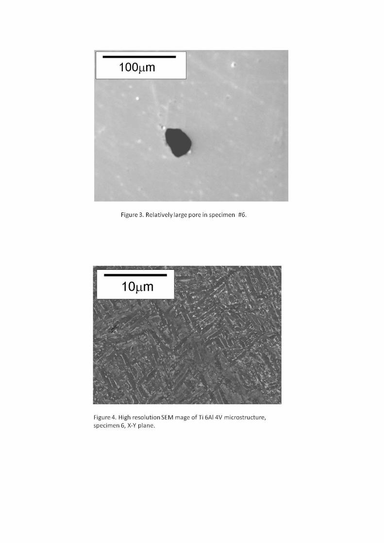
Micro-porosity was found to be widespread throughout the individual specimens,
however, these very fine scale pores were typically less than 1μm in diameter. In
specimen #4 (extracted at the mid length position of a relatively thin wall), a single 10
μm pore was detected. The largest example was found in specimen #6 at
approximately 40 μm in diameter (this relates to an oblique intersection), Figure 3.
Examinations from the orthogonal sections confirmed that the porosity was essentially
equiaxed and not elongated in any preferred axis relative to the DLD epitaxy. No
evidence of angular porosity or lack of fusion within the build pattern was detected.
Metallographic examination
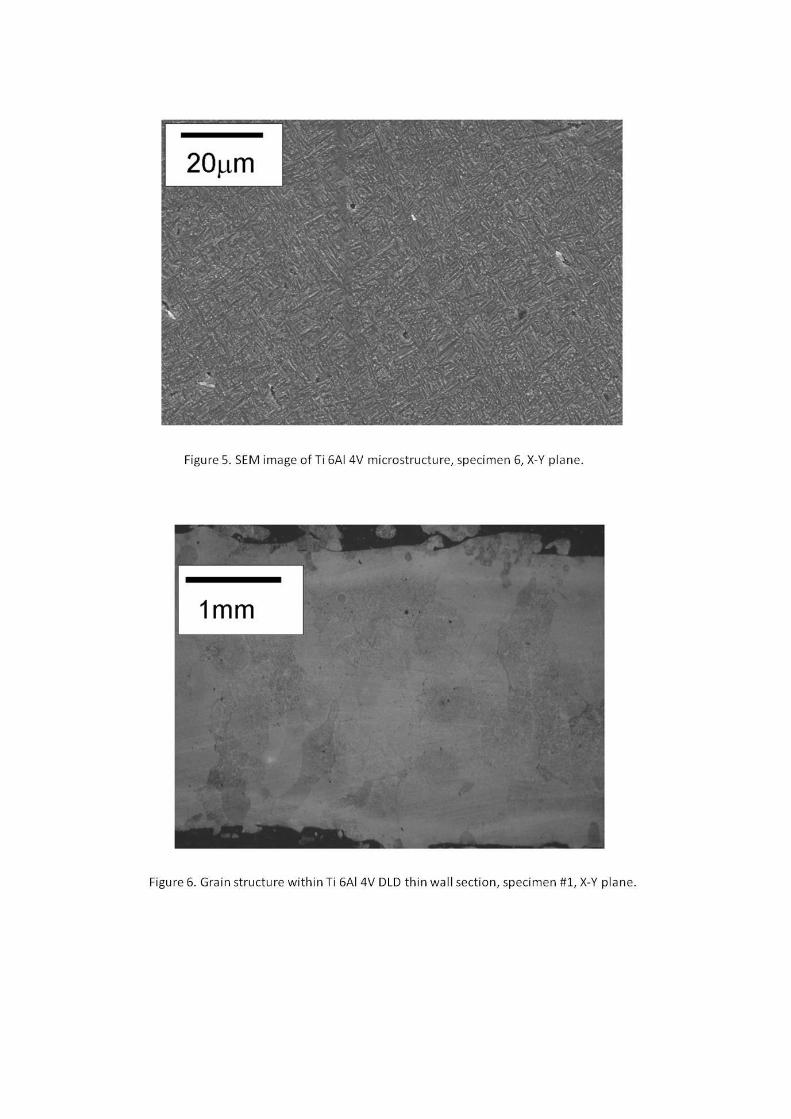
A Widmanstätten type microstructure was observed in each of the specimens
irrespective of wall thickness and local ligament geometry, Figures 4 & 5. The
maximum α lath length was of the order of 5 μm, with thicknesses of approximately 1
μm. This type of structure is consistent with that seen in previous characterisations of
welded forms of Ti 6Al 4V (including electron beam and TIG welds) and is common
for the alloy immediately after cooling through the β transus (i.e. as cast and solidified
but prior to subsequent working)[21]
.
Lower magnification optical microscopy was used to examine the prior β grain size,
Figures 6 & 7, ranging from 0.1 mm up to approximately 1 mm. The Widmanstätten
structure within these grains, however, was consistent. It should be noted, that there
were slight deviations in the thickness of the α laths between individual prior β grains.
However, there was no correlation of this coarsening with wall thickness or proximity
to the outer surface of the structure.
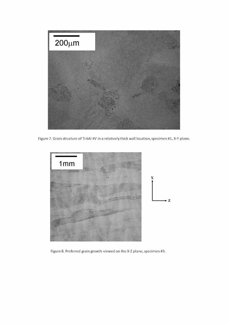
Although the grains in Figures 6 and 7, representing the X-Y plane, appear essentially
equiaxed, evidence of appreciable grain elongation was noted in the X-Z and Y-Z
planes, Figure 8. This illustrates preferential grain growth parallel to the axis of DLD
deposition. This is consistent with previous empirical evidence.
The potential for grain boundary α was of specific interest. Some examples were
detected, Figure 9, however, these were infrequent and restricted to specimen #3. The
α phase was never continuous around any single grain.
When inspected by eye, the external surface finish of the whole DLD component was
notably rough. When viewed in section at high magnification, e.g. top and bottom
edges in Figure 6, significant geometric irregularities were noted. It has been
recognised that such re-entrant features on the surface could offer many potential sites
for fatigue crack initiation should the component be aggressively loaded. Therefore,
surface machining or acid pickling may be envisaged for eventual components. The
current sections suggest that to completely eliminate this surface topography,
approximately 0.5 mm of surface material would require removal. It can be confirmed
that no α case was evident on the component surfaces.
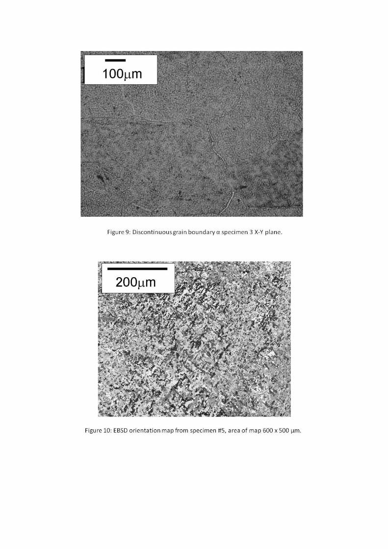
EBSD mapping was also employed to characterise crystallographic orientations and
texture. Relatively large areas of sample #5 were scanned on the Y-Z plane in order to
identify whether any localised areas of strong texture were apparent, along with
providing a measure of the bulk material crystallographic orientation. Individual
orientation maps sampled an area of approximately 0.6 x 0.5mm, using a step size of
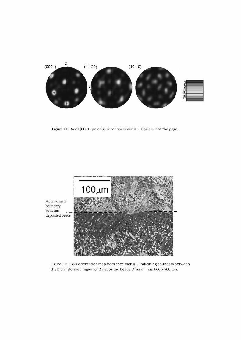
2μm. Figure 10 shows three orthogonal pole figures (basal, type I prismatic and type
II prismatic) which describe the crystallographic texture of the material. It can be seen
that the measured texture is typical of material which has been processed above the
beta transus[22]
, with strong individual poles representing orientations favoured by the
Burger’s transformation. The fact that these poles lie slightly off-axis may be related
to the axis of epitaxy of the specimen during DLD build-up. Figure 11 indicates that
despite these strong poles, no large effective structural units appear to exist within the
microstructure, which should be beneficial for fatigue performance[23]
.
Orientation maps were produced at 1mm intervals in both the Y and Z directions to
investigate whether individual beads of deposited material showed variations in
crystallographic texture. Although some minor rotation of the poles was seen about
the X axis (out of the page), this was not significant and there was little evidence of
significant change in microtexture. However, it was possible to distinguish the
boundaries between deposited beads, Figure 12.
Hardness
Three Vickers hardness measurements together with the calculated average for each
specimen are presented in Table 1. Clearly, good consistency is noted between the
data irrespective of location in the component. These values are also consistent with
typical values for Ti 6Al 4V[24]
in either rolled plate or forged disc forms.
Discussion
Given that the current trials formed part of an early stage programme of process
evaluation and selection, the structure examined could be considered as pre-optimised
in terms of microstructural control. Despite this, the general findings appear to be
encouraging. Throughout the metallographic sections, a minimal degree of porosity
was noted and where evident individual pores were extremely fine scale,
corresponding to the pin hole porosity[25]
noted by Goodwin et al. Kobryn et al[14]
also
noted porosity in the gauge volume of mechanical test specimens, some of which was
due to lack of fusion. Whilst only one pore of this type was found in the present study,
it is recognised that this may be a statistical effect due to the volumetric distribution,
the two dimensional technique used for assessment and the relatively small areas
sampled. Three dimensional inspection techniques such as computed tomography
could provide a more accurate measurement of actual porosity in such structures.
The microstructure was consistent at all the sampled locations, irrespective of wall
thickness, orientation and local heat sink conditions. This compares favourably with
casting processes for example. However, it is recognised that the DLD material
requires detailed mechanical assessment alongside further process optimisation. In
particular, this mechanical assessment must consider the potential for orientation
effects that may result from the planar nature of the DLD build process. The crystal
orientation maps for the current material, however, are encouraging in this respect,
particularly the lack of textural variation along both the Y and Z directions. Whilst a
transformation texture typical of processing is evident, there is no strong textural
alignment with either the X,Y or Z axes. As such, mechanical loading in any of these
directions would probably show a minimal orientation effect. An evaluation of
mechanical properties of the current material would be required to validate these
theories. The fact that no large effective structural units, which could prove
detrimental to fatigue properties, were evident is also encouraging. However, it should
also be noted that Kobryn[14]
et al found evidence of anisotropic yield strength, fatigue
response and an unusual planar response associated with porosity for compact tension
samples. This planar porosity was also found in the work by Groh[26]
.
The preferred epitaxy within prior grains, with grains elongated parallel to the axis
of build, is consistent with previously reported studies[25, 14]
. This is an important
feature to note given the deliberate complexity of build pattern employed during the
current trials in contrast to some of the simpler forms of test geometries reported by
previous authors. Ultimately, it can be presumed that the transus isotherm generated
during the current process must have remained essentially perpendicular to the build
axis. The complex interaction of tool-path, molten pool volume, depth, time period
and percentage of overlap and cooling duration will affect this isotherm. Specific
control of either of these variables could be considered in an attempt to influence the
alignment and pattern of grain orientations. Control would need to be in relation to a
validated process model for microstructural generation and could be via finite element
approaches[27,28]
, where each cell has phase transformation information, or reverse
engineered from measured process data.
The size of the prior grains (i.e. maximum length parallel to the build axis) was
similar to those reported by Kobryn and Semiatin using a much more powerful laser
source with increased melt pool and presumably decreased freezing rate[14]
. Grain
width and porosity population appear to be finer. The β grain morphology is
controlled by the combination of the thermal gradient and the cooling rate. The
solidification velocity is related to the thermal gradient and cooling rate by –
1.
TR
G dt
(1)
where R is the solidification velocity, G the thermal gradient and T/dt the cooling
rate[29]
. The thermal gradient is a function of the previous layer and the bead heat
retention and also the bead size of the successive layer, i.e. the local molten mass and
the processing rate. The evolved substrate temperature will be in a process control
range limited by economic processing rate and also the danger of excess heat
localisation, which may cause morphological coarsening and potentially also
distortion. This clearly indicates that additional parameters such as those already
discussed are important in controlling grain morphology and size[30]
. The morphology
of the laths has previously been modelled for wire based deposition[31,32]
. It is
pertinent to compare these microstructures to those evolved from competing cast
processes. The latter will tend to produce relatively large, equi-axed grains
encompassing relatively coarse α laths at > 5 microns. This lath size is typically
reduced in forged Ti 6Al 4V variants at approximately 1-2 microns. The lath size in
the present examples was restricted to approximately 1 μm and can be compared with
the near equiaxed-like morphology with a smaller aspect ratio of laths described by
Dinda et al[33]
. Thus, the additive process clearly generates refined microstructure
which in turn should offer benefits to mechanical strength and fatigue.
With regard to the banding seen by other researchers with similar conditions, the
authors have seen this effect in SMD using TIG processes. Others[34]
have seen this as
a banded variation in reflectivity for microsamples from material formed via laser
diode and wire Ti 6Al 4V deposition. That such an effect was not observed in this
study may be due to the thermal processing rate, particularly the isotherm velocities
being substantial, and the interpass temperature, time, remelting and recrystallisation
allowing sufficient solid phase diffusion of any concentrated -strengthening
elements to be dispersed.
From a compositional viewpoint, X-ray spectrographic measurements of local
chemistry were consistent at randomly chosen sites throughout the structure. Previous
workers have postulated episodes of local segregation due to variations in elemental
density and distribution within the melt pool. Variable heat concentrations with
successive beads and stop-start events may also lead to volatilisation[35]
of specific
elements (e.g. aluminium and vanadium). This does not appear to be evident in the
current material, however, the resolution of the EDX equipment may not be sufficient
to detect the effect. However, the consistent α lath sizes noted throughout the structure
do not support any great variation on local chemistries, either due to issues of
buoyancy or variable superheat. Within the grain structure, only sporadic examples of
isolated grain boundary were noted, consistent with relatively fast cooling rates.
Together with the absence of surface case this would be considered beneficial to
subsequent high cycle fatigue properties.
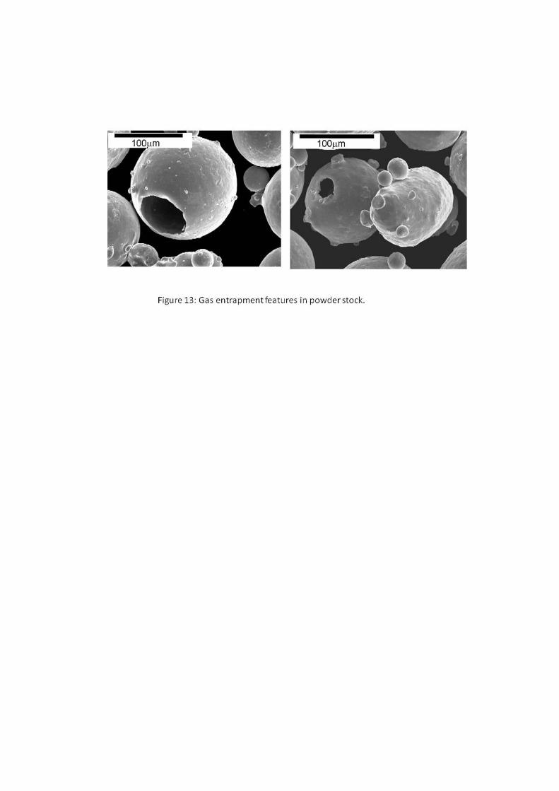
Although minor examples of porosity were found, the source of this porosity is
difficult to define. However, it should be noted that even individual sourced powder
particles can contain gas entrapment features due to the instabilities of the atomisation
process, Figure 13[36]
. Blown powder deposition allows component manipulation,
although toolpath trajectories over complex contours may not always be perpendicular
to gravity. Process conditions may affect pool fluidity, pool shape and process rate,
hence time for floatation. Removing the argon shielding gas, as done in electron beam
based deposition would remove a possible source of porosity. Deposition at reduced
pressure would be expected to increase the intensity of nucleation of gas bubbles and
also allow greater vaporisation of metallic elements whereas a higher pressure would
make porosity more difficult. Shallow pools restrict the metallostatic pressure, which
can limit bubble stability, this may mean that other factors being equal, there would
be an increased number of pores for the same volume when created from a fine build
technique as observed in the current material.
All current hardness measurements were slightly above those previously reported[37]
for the higher deposition rate ‘AeroMat’ material. This may be explained by the faster
cooling indicated by the finer microstructure of the samples examined in this study.
This comparative result supports the modeled findings of Qian et al [18, 38]
, who
reported that for the same volumetric form, created with varying build up rates
through changing the pool voxel dimensions with similar processing speeds, there is a
linkage of cooling rate to pool size. The surface finish seen in this study did not
approach that reported elsewhere[39]
(7-7.5 μm Ra). Clearly the surface finish will
affect process rate, yield and the need for and degree of subsequent processing before
inspection and final condition of use is achieved. Refinement of this issue is clearly
necessary to achieve optimum in service material conditions.
Conclusions
The DLD component contained a low volume of spherical micro-porosity,
with pore diameter <1μm. The single largest pore found within the structure
was approximately 40 μm in diameter.
The material contained a Widmanstatten microstructure, characteristic of
cooling from above the β transus. The α laths within the Widmanstatten
microstructure were approximately 5 μm long and 1 μm thick. Only minor
variations in these dimensions were noted between individual prior β grains.
Grain elongation was noted parallel to the axis of DLD epitaxy / build up.
Limited grain boundary α was detected, although never continuous around any
particular grain.
EBSD analysis confirmed a moderate Burgers texture within the
microstructure, typical of a cast titanium alloy cooling through the β transus.
However, the microstructure was found to be more uniform than a comparable
casting, which may have implications for mechanical response and volumetric
inspection
Acknowledgements
The authors would like to acknowledge the financial and technical support of Rolls-
Royce plc in the production of this work.
References
[1] K. G. Swift, J. D. Booker, Process Selection, (2nd Edition). Butterworth-
Heinemann, Oxford, UK, 2003 pp. 300
[2] L. Xue, A. Theriault, B. Rubinger, D. Parry, F. Ranjbaran and M. Doyon,
Proceedings of the 22nd International Congress on Applications of Lasers and
Electro-Optics 2003. Published on CD ROM.
[3] L. Xue, A. Theriault, M.U. Islam, M. Jones, H.-P. Wang, Proceedings of the 23rd
International Congress on Applications of Lasers and Electro-Optics 2004. Published
on CD ROM.
[4] S. Zheng, P. Dayou, Z. Weihong, T.Y. Kuang. SIMTech Technical Report.
(PT/01/015/JT). Singapore Institute of Manufacturing Technology. Joining
Technology Group. Process Technology Division. 2001. www.simtech.a-
star.edu.sg/Research/TechnicalReports/TR0120.pdf
[5] S. Nowotny, S. Scharek, E. Beyer, K.H. Richter, Journal of thermal spray
technology, Vol.16 No.3, 2007, pp. 344-348
[6] P.A. Kobryn and S.L. Semiatin "The Laser Additive Manufacture of Ti-6Al-4V"
(Overview), September 2001, pp. 40-42.
[7] Y. Li, H. Yang, X. Lin, W. Huang, J. Li and Y Zhou, Materials Science and
Engineering A360, 2003, pp. 18-25.
[8] J. Kim, Y. Peng, Journal of Materials Processing Technology Vol.104, 2000, pp.
284-293.
[9] A. Pinkerton and L. Li, Journal of Engineering Manufacture, Vol 218, 2004, pp.
363-374.
[10] A.J. Pinkerton and L. Li, Journal of Manufacturing Science and Technology,
Vol.126 No.1, 2004, pp. 34-42.
[11] A.J. Pinkerton and L. Li, International Journal of Machine Tools and
Manufacture, Vol44 No.6, 2004, pp. 573-584.
[12] A. Pinkerton and L. Li, Journal of Mechanical Engineering Science, Vol.218
No.6, 2004, pp. 531-541.
[13] J.Lawrence and L.Li, Journal of Laser applications, Vol.14, no.2, (May 2002),
pp. 107-113.
[14] P.A. Kobryn, S.L. Semiatin, In proc. conf. Solid Freeform Fabrication
Symposium 2001, ed.s D.L.Bourell, J.J.Beaman, R.H.Crawford, H.L.Marcus,
K.L.Wood, J.W.Barlow, publ. by The Univ. of Texas at Austin, Texas, USA, 2001,
pp. 179-186.
[15] C. Hu and T.N. Baker, Metallurgical and Materials Transactions, A. Vol 27A,
1996, pp. 4039-4047
[16] B. Baufeld, O. van der Biest, R. Gault, AEROMAT 2008, ASM International,
23-26 June 2008, Austin Texas, USA. Published on CD-ROM
[17] S.M. Kelly and S.L. Kampe, Metallurgical and materials transactions. A, Vol. 35,
No 6, 2004, pp. 1869-1879.
[18] S.M. Kelly, S.L. Kampe, C.R. Crowe, In proc. conf. Solid Freeform and Additive
Fabrication – 2000, compiled by S.C.Danforth, D.Dimos, F.B.Prinz, publ. by MRS,
USA, 2000, pp. 3-8.
[19] P.S. Goodwin, C. Mitchell, J. Liang, J.M. and X. Wu, In proc. conf. Metal
Powder Deposition for Rapid Manufacturing 2002, compiled by D. Keicher, J.W.
Sears, J.E. Smugeresky, publ. by MPIF, 2002, pp. 87-94.
[20] L. Qian, J. Mei, X. Wu, Materials science, 2007, vol. 539-43 (4), pp. 3637-3642.
[21] F. Wagner, N. Bozzolo, O. van Landuyt and T. Grosdidier, Acta Materialia, Vol.
50, 2002, pp. 1245-1259.
[22] G. Lutjering, Material Science & Engineering A243, 1998 pp. 32-45.
[23] M.T. Whittaker, W.J. Evans, R. Lancaster, W. Harrison, P.S. Webster.
International Journal of Fatigue, Vol. 31 Nos.11-12, 2009, pp. 2022-2030.
[24] S.R. Tuppen, M.R. Bache, W.E. Voice, International Journal of Fatigue, Vol. 27
No. 6, 2005, pp. 651-658.
[25] P.S. Goodwin, C. Mitchell, J. Liang, J. Mei and X. Wu, Proceedings of Metal
Powder Deposition for Rapid Manufacturing, , San Antonio Texas, USA, 8-10th
April,
2002, pp. 87-94.
[26] C. Henry III., NASA/TM—2006-214256, 2006. http://gltrs.grc.nasa.gov/
reports/2006/TM-2006-214256.pdf
[27] L-E Lindgren “Computational Welding Mechanics”, CRC Press, 2007.
[28] A. Crespo, A. Deus, R. Vilar, Paper 2005, ICALEO 2006,
http://www.lia.org/store//ICAL06_2005.
[29] N.W. Klinbeil, C.J.Brown, S. Bontha, P.A. Kobryn, H.L. Fraser, Proceedings of
the Solid Freeform Fabrication Symposium, 2002, University of Texas, Austin, USA,
pp.142-149.
[30] S.M. Kelly, S.S. Babu, S.A. David, T. Zacharia and S.L. Kampe, in 7th
International Conference on Trends in Welding Research, May 16-20, 2005, Pine
Mountain, GA, USA, 2005, pp. 65-70.
[31] C. Charles, N. Järvstråt, 8th International Conference on Trends in welding
research, Pine Mountain, Georgia, June 2-6, 2008. Published on CD-ROM.
[32] C. Charles and N. Järvstråt, Proceedings of the 11th World Conference on
Titanium Kyoto, Japan, 2007, pp 1201-1204.
[33] G.P. Dinda, L. Song, and J. Mazumder, Met. Mat. Trans. A, Vol. 39A, 2008, pp.
2914-2922.
[34] S.D. Sharples, M. Clark, W. Li, M.G. Somekh 1st International Symposium on
Laser Ultrasonics, Science, Technology and Applications, July 16-18 2008, Montreal,
Canada. http://www.ndt.net/article/laser-ut2008/papers/Sharples%20LU2008.
[35] C.L. Lach, K.M. Taminger, AEROMAT 2008, ASM International, 23-26 June
2008, Austin Texas, USA. Published on CD-ROM.
[36] J. Forsdike, MRes Thesis, Swansea University, 2006.
[37] L. Qian, J. Mei, and X. Wu, “The Influence of position and laser power on the
thermal history in a direct laser fabricated Ti alloy”, Mat. Sci. & Tech, Vol. 21 No. 5,
2005, pp. 597-605.
[38] L. Qian, J. Mei, and X. Wu, Materials Science Forum, Vol 539-543, 2007.
[39] Xue, L., J.-Y. Chen, and A. Theriault, “Laser Consolidation of Ti-6Al-4V Alloy
for the Manufacturing of Net-Shape Functional Components”, Proceedings of
ICALEO' 2002, Scottsdale, Arizona, USA, October 14-17, 2002, pp. 169-178.
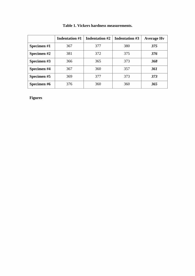
Table 1. Vickers hardness measurements.
Figures
Indentation #1 Indentation #2 Indentation #3 Average Hv
Specimen #1 367 377 380 375
Specimen #2 381 372 375 376
Specimen #3 366 365 373 368
Specimen #4 367 360 357 361
Specimen #5 369 377 373 373
Specimen #6 376 360 360 365
Recommended


![Cronfa - Swansea University Open Access Repository · ô ½ ·W=m] Y](https://img.pdfslide.us/doc/110x75/5e086d1104eac94d302c30f1/cronfa-swansea-university-open-access-repository-wm-y.jpg)