IOSR Journal of Electrical and Electronics Engineering (IOSR-JEEE)
e-ISSN: 2278-1676,p-ISSN: 2320-3331, Volume 10, Issue 1 Ver. II (Jan – Feb. 2015), PP 18-32 www.iosrjournals.org
DOI: 10.9790/1676-10121832 www.iosrjournals.org 18 | Page
Controllers For A VSC-HVDC Link Connected To A Weak AC
System
R.S. Geetha1, Ravishankar Deekshit
2, G.Lal
3,
1Department of Electrical and Electronics, BMS College of Engineering, Bangalore,India 2Electronics Division, BHEL, Bangalore, India
Abstract: In this paper, the interconnection of a strong AC system to a weak AC system by using a Voltage
Source Converter (VSC) based High Voltage DC (HVDC) transmission system is investigated. In this work, the
weak AC system considered is an island system comprised of synchronous generators and passive load. Analysis
is carried out for UPF load and inductive load. The ac filter requirement to achieve the required response for
UPF and inductive load is carried out. For efficient functioning of the system considered, proper designing of
the controllers is an important factor. The controller parameters are designed using Modulus Optimum
technique and Symmetric optimum method. The performance analysis of VSC-HVDC is carried out for power
transmission in the DC link for load variation in the island system. Simulations are carried out in MATLAB/
Simulink / Sim Power Systems and the results are presented.
Keywords: Voltage Source Converter; PI controllers parameters; VSC-HVDC; Modulus optimum; Symmetric
optimum; weak AC system; island system; Power order
I. Introduction For HVDC transmission, the strength of the ac system is important for normal operation. A measure of
the strength of the ac system is given by the short circuit ratio (SCR). SCR is defined as the ratio between the
short circuit capacity of the ac network and the nominal DC power level. An AC system is usually regarded as
weak, if SCR is lower than 3 [1]. In the conventional line-commutated HVDC technology, the commutation of
the converter valves is dependent on the stiffness of the alternating voltage supplied by the ac system. The
converter cannot work properly if the connected ac system is weak [2]. Some of the important consequences that
are to be addressed when a HVDC system is connected to a weak AC system are: high temporary over voltages,
low frequency resonances, risk of voltage/power instability, long restart times and high risk of commutation failures[1] [3][4]. Synchronous condensers can be used to increase the short circuit capacity of the AC system.
But, the use of synchronous condensers substantially increases the investment and maintenance cost of the
HVDC project. With the advent of semiconductor technology, devices with turn off capability like Gate Turn
Off Thyristor (GTO) and Insulated Gate Bipolar Transistor (IGBT) make the Voltage Source Converter (VSC)
attractive for HVDC transmission[5]. Some of the problems faced in connecting HVDC transmission system to
a weak AC system can be overcome by using VSC based HVDC system (VSC-HVDC). Among many
advantages of VSC-HVDC [6][7], the property of independent control of active and reactive power may be used
for overcoming the problem of voltage/power instability, when HVDC system is connected to a weak AC
system.
The voltage/power controllability of the VSC-HVDC system is determined by the controllers included
in the system. Adequate performance of the VSC-HVDC system under diverse operating conditions depends on the selection of robust parameters for the control system [8]. Usually, due to their simple structure and
robustness, PI controllers are used to adjust the system for desired response. An overview of VSC-HVDC
technology is given in [9], wherein some aspects of model and control are discussed. A control system for VSC-
HVDC during island operation is proposed in [10], and it has been found that, the current limit of the converter
has a significant influence on the dynamic response of the system. Control methodologies based on sliding
mode control for controlling active and reactive power are addressed in [11]. An optimal control strategy for a
HVDC light system using a direct current vector control mechanism is proposed in [12], where the control
mechanism operates by either using PI control technique, or integrating PI, fuzzy and adaptive control
techniques together. Different control approaches like Internal Model Control (IMC) and H∞ control are
applied for designing controllers for VSC-HVDC connected to weak AC systems [13]. These two design
approaches are used for power-synchronization control, which has also been proposed for interconnection of
two very weak AC systems [2] . The power synchronization control method is similar to power angle control method and uses phase angle and voltage magnitude to directly control active power and reactive power.
Typical problems such as resonant peak at grid frequency and converter over current limitation are taken care in
power synchronization method [14]. The modeling and control of VSC-HVDC links connected to Island
Systems is discussed in [15]. The control method in this paper is based on the power synchronization control for
Controllers for a VSC-HVDC link connected to a weak AC system
DOI: 10.9790/1676-10121832 www.iosrjournals.org 19 | Page
grid connected VSCs. In [16], a sliding mode controller is proposed for a VSC-HVDC transmission link, and
results have been provided for a variety of operating conditions such as, changes in short circuit ratio, converter
parametric changes, and faults on the converter and inverter buses. A detailed discussion on tuning techniques of converter controllers for VSC-HVDC is carried out in
[8], by using Modulus optimum method and Symmetric optimum method for a system that is comprised of an
ac source/ grid connected to a Pulse Width Modulated (PWM) VSC. The control of the converter aims at
regulating the dc voltage Vdc and maintaining a balance between the dc link power and ac power supply.
In this work, the control techniques described in [8], are used for the analysis of behavior of a VSC-
HVDC system connected to an island system . The island system chosen is a weak AC system with synchronous
generators of total short circuit rating of 516MVA and passive load. The analysis is carried out for UPF load, as
well as for an inductive load of 0.85 power factor. The total active load in the island system is assumed to be of
400MW, out of which, 300MW is considered to be a critical load, that has to be supplied by the VSC-HVDC
transmission system. Hence, the VSC-HVDC link is designed to supply a maximum load of 300MW. The
difference power is supplied by the synchronous generators in the island system. The simulation is carried out for different load settings. Remaining part of the paper is organized as follows: In section II, the topology of the
system under consideration is explained. In section III, the tuning of the controllers for the considered system are
presented. In section IV, the dynamic performance of the active power controller, reactive power controller, DC
voltage controller and AC voltage controller are carried out. Also, the operation of VSC-HVDC link for load
variation in the island system is analyzed.
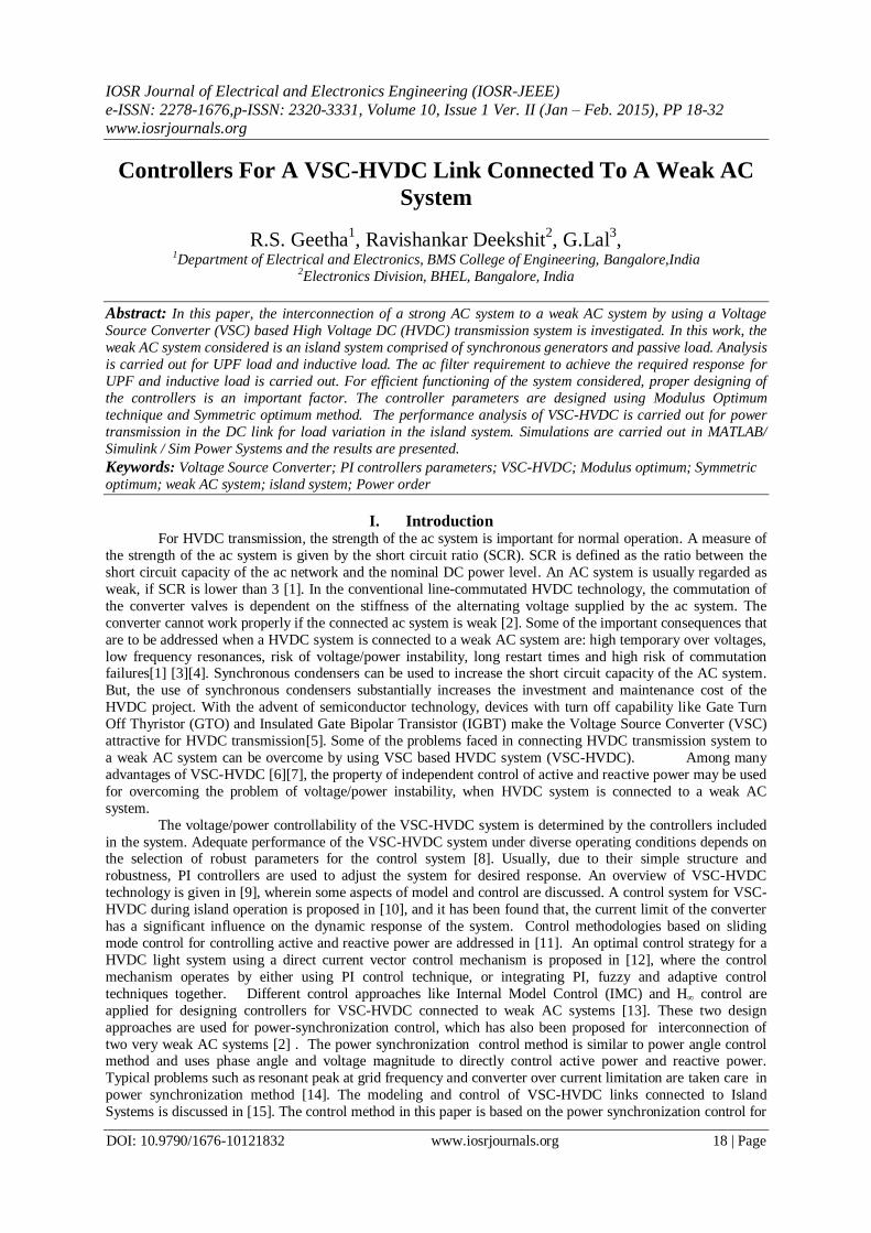
II. Circuit Topology Fig. 1 shows the topology of the VSC-HVDC system connected to a weak AC system. The topology involves two
VSCs, VSC-1 and VSC-2. VSC-1 is a rectifier and VSC-2 is an inverter. VSC-1 is connected to a strong AC system through reactor and converter transformer. VSC-2 is connected to an island system, which is a weak AC
system represented as AC system-2. The two converters are linked through a DC cable. The phase reactors
smoothen the current and secure the power exchange between AC system and DC link. The capacitors are used
for voltage support and harmonic attenuation.
Fig. 1. Basic VSC based HVDC scheme connected to an island system
III. Tuning Of The Controllers Depending on the type of controllers used, the main control topologies for VSC station are: 1)Fixed DC
voltage control mode 2) Fixed DC current or power control mode 3) Fixed AC bus voltage control mode
4)Variable frequency control mode. Usually in the VSC-HVDC transmission systems, one VSC station uses
fixed DC voltage control mode and the other uses fixed DC current control mode or fixed AC bus voltage
control mode according to the requirement [17],[18]. In this work, the maximum power in the DC link is
restricted to 300MW. Hence, an active power controller is used in the rectifier side of the DC link. The reactive power controller used in the rectifier side controls the reactive power exchange between the VSC-1 and AC
system-1 to maintain constant voltage at PCC. Since it is important to maintain the DC link voltage constant at
the inverter input terminals, a DC voltage controller is used on the inverter side. In addition to this, AC voltage
controller is also used in the inverter side to maintain constant AC voltage at the inverter output. For proper
steady state and dynamic performance of these controllers, it is required to tune the controller parameters. In the
following sections, tuning techniques used for different controllers of the system considered are described.
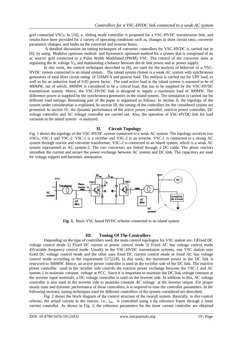
Fig. 2 shows the block diagram of the control structure of the overall system. Basically, in this control
scheme, the actual current in the reactor, i.e., iabc is controlled using a dq reference frame through a inner
current controller. As shown in Fig. 2, the reference parameters for the inner current controller are obtained
Controllers for a VSC-HVDC link connected to a weak AC system
DOI: 10.9790/1676-10121832 www.iosrjournals.org 20 | Page
from the outer controllers, namely, active power controller, reactive power controller, DC voltage controller and
AC voltage controller. In such cascade control structure, the inner loop response must be faster when compared
to the speed of response of the outer loop. Hence, internal loop is designed to achieve fast response. The inner loop is tuned according to “Modulus optimum” condition because of fast response and simplicity. This method
provides a relatively fast and non-oscillatory closed-loop tracking response.
Fig.2 Block diagram of control strategies for VSC_HVDC
3.1.1 Modulus Optimum Tuning Criteria
For low order controlled plants without time delay, the modulus optimum (absolute value optimum
criterion) is often used in the conventional analog controller tuning [19]. When the controlled system has one
dominant time constant and other minor time constant, the standard form of the control system transfer function
for the modulus optimum is achieved by cancelling the largest time constant, while the closed loop gain should be larger than unity for as high frequencies as possible [8]. This method is widely used because of its simplicity
and fast response.
The outer controllers have to be relatively slower when compared to the inner current controller. One tuning
technique that satisfies this criteria is the Symmetrical Optimum tuning method.
3.1.2 Symmetrical Optimum method
A symmetrical optimum design criterion results in a controller that forces the frequency response of the
system as close as possible to that for low frequencies. In this method, the phase margin is maximized. As phase
margin is maximized for given frequency, the system can tolerate more delays. This method optimizes the
control system behaviour with respect to disturbance input. The method has well established tuning rules and
has good disturbance rejection [20]. An extended approach of tuning by symmetric optimum is presented in
[21]. The various controllers used in this work are explained in detail in the following section. In the ensuing discussions, the various reference parameters and output values of the controller block are in per unit.
3.2.1 Inner Current Controller
The basic equation describing the system behavior for the rectifier mode of operation is given by equation (1).
11
11 tabcsabc
sabcsabc vdt
diLRiv (1)
where, vsabc1 is the balanced 3phase voltage of the AC system-1, vtabc1 is the converter input voltage, L is the
reactor inductance and R is the reactor resistance.
Transforming equation (1) to dq frame,
tdsqsdsd ViLuV
(2)
tqsdsqsq
sq ViLRidt
diLV
(3) The voltage across the reactor is represented as usd, and is given by
sdsdsd
sd iRLsRidt
diLu
(4)
Controllers for a VSC-HVDC link connected to a weak AC system
DOI: 10.9790/1676-10121832 www.iosrjournals.org 21 | Page
where, Vsd, Vsq are the d and q components of ac voltage Vabc1 , usd is the d component of the voltage drop across
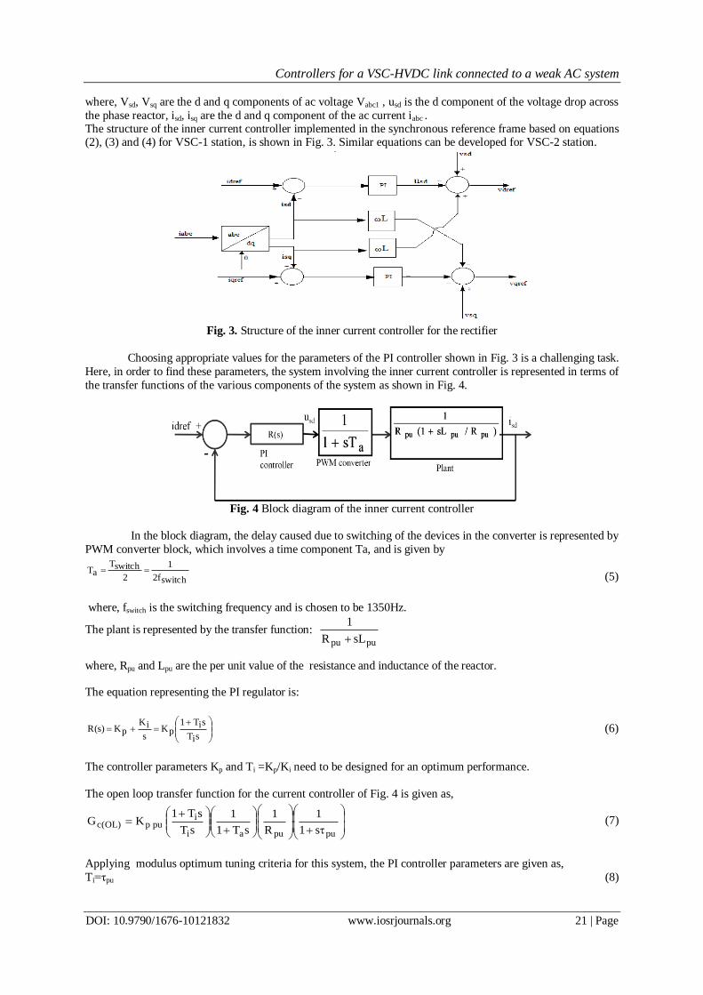
the phase reactor, isd, isq are the d and q component of the ac current iabc . The structure of the inner current controller implemented in the synchronous reference frame based on equations (2), (3) and (4) for VSC-1 station, is shown in Fig. 3. Similar equations can be developed for VSC-2 station.
Fig. 3. Structure of the inner current controller for the rectifier
Choosing appropriate values for the parameters of the PI controller shown in Fig. 3 is a challenging task.
Here, in order to find these parameters, the system involving the inner current controller is represented in terms of
the transfer functions of the various components of the system as shown in Fig. 4.
Fig. 4 Block diagram of the inner current controller
In the block diagram, the delay caused due to switching of the devices in the converter is represented by
PWM converter block, which involves a time component Ta, and is given by
switchf2
1
2
switchTaT
(5)
where, fswitch is the switching frequency and is chosen to be 1350Hz.
The plant is represented by the transfer function: pupu sLR
1
where, Rpu and Lpu are the per unit value of the resistance and inductance of the reactor.
The equation representing the PI regulator is:
siT
siT1pK
s
iKpK)s(R (6)
The controller parameters Kp and Ti =Kp/Ki need to be designed for an optimum performance.
The open loop transfer function for the current controller of Fig. 4 is given as,
pupuai
ipup)OL(c
s1
1
R
1
sT1
1
sT
sT1KG (7)
Applying modulus optimum tuning criteria for this system, the PI controller parameters are given as,
Ti=τpu (8)
Controllers for a VSC-HVDC link connected to a weak AC system
DOI: 10.9790/1676-10121832 www.iosrjournals.org 22 | Page
pu
pupu
R
L (9)
a
pupupup
T2
RK ; (10)
Hence, the open loop and closed loop transfer functions of the current control loop are given by equations (11)
and (12) respectively.
)saT1(s
1
aT2
1)OL(cG (11)
1saT22s2aT2
1)CL(cG (12)
The resulting system has a frequency of natural oscillation
2T
1
a
n and damping factor
2
1.
3.2.2 Active power controller
The active power (Pac) is expressed in d and q components of the voltage and current [21], and is given by
equation (13). In steady state, vsq=0 and hence, Pac is given by equation (14).
)]t(i)t(v)t(i)t(v[2
3)t(P sqsqsdsdac (13)
)]t(i)t(v[2
3)t(P sdsdac
(14)
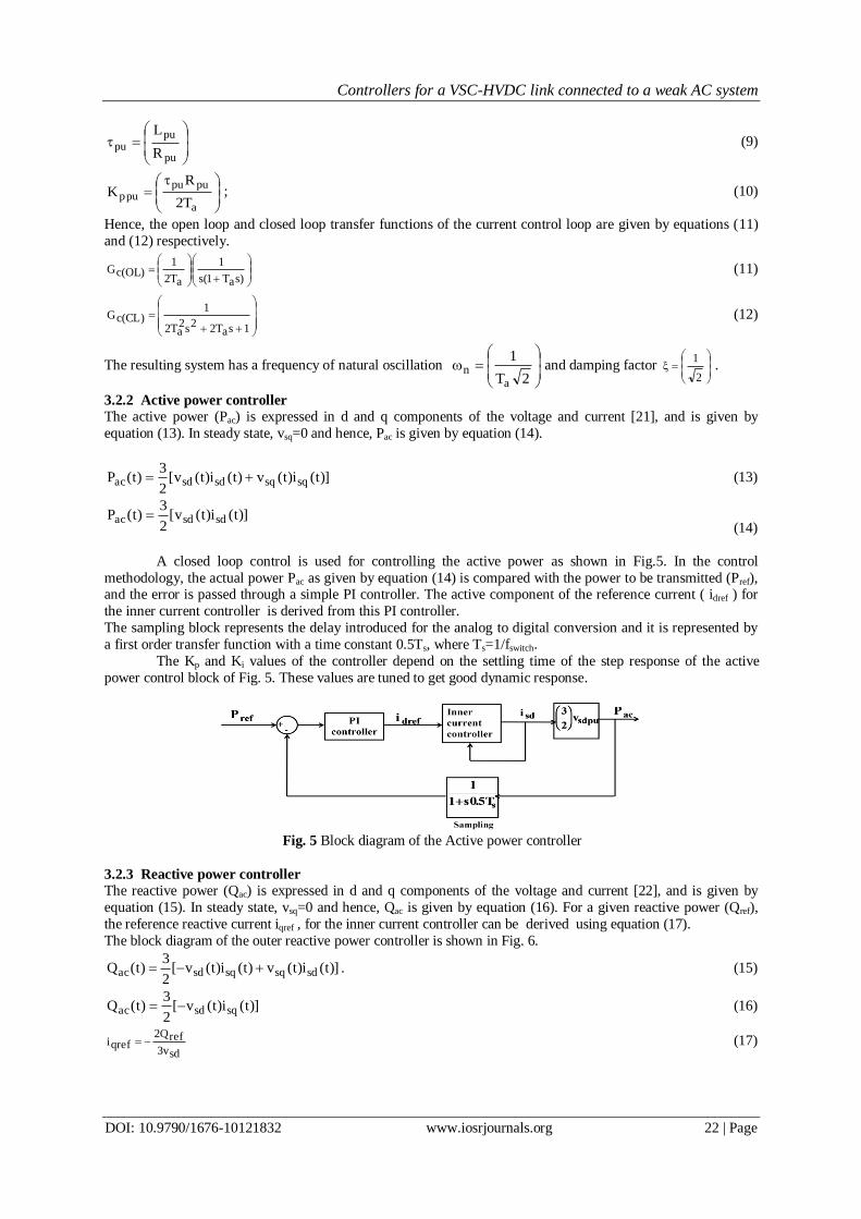
A closed loop control is used for controlling the active power as shown in Fig.5. In the control
methodology, the actual power Pac as given by equation (14) is compared with the power to be transmitted (Pref), and the error is passed through a simple PI controller. The active component of the reference current ( idref ) for
the inner current controller is derived from this PI controller.
The sampling block represents the delay introduced for the analog to digital conversion and it is represented by
a first order transfer function with a time constant 0.5Ts, where Ts=1/fswitch.
The Kp and Ki values of the controller depend on the settling time of the step response of the active
power control block of Fig. 5. These values are tuned to get good dynamic response.
Fig. 5 Block diagram of the Active power controller
3.2.3 Reactive power controller
The reactive power (Qac) is expressed in d and q components of the voltage and current [22], and is given by
equation (15). In steady state, vsq=0 and hence, Qac is given by equation (16). For a given reactive power (Qref),
the reference reactive current iqref , for the inner current controller can be derived using equation (17).
The block diagram of the outer reactive power controller is shown in Fig. 6.
)]t(i)t(v)t(i)t(v[2
3)t(Q sdsqsqsdac .
(15)
)]t(i)t(v[2
3)t(Q sqsdac (16)
sdv3
refQ2qrefi (17)
Controllers for a VSC-HVDC link connected to a weak AC system
DOI: 10.9790/1676-10121832 www.iosrjournals.org 23 | Page
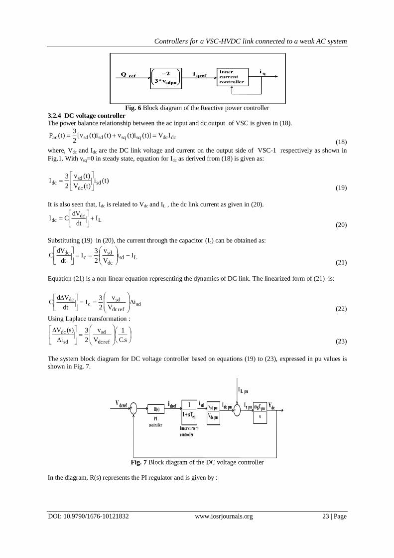
Fig. 6 Block diagram of the Reactive power controller
3.2.4 DC voltage controller The power balance relationship between the ac input and dc output of VSC is given in (18).
dcdcsqsqsdsdac IV)]t(i)t(v)t(i)t(v[2
3)t(P
(18)
where, Vdc and Idc are the DC link voltage and current on the output side of VSC-1 respectively as shown in
Fig.1. With vsq=0 in steady state, equation for Idc as derived from (18) is given as:
)t(i)t(V
)t(v
2
3I sd
dc
sddc
(19)
It is also seen that, Idc is related to Vdc and IL , the dc link current as given in (20).
Ldc
dc Idt
dVCI
(20)
Substituting (19) in (20), the current through the capacitor (Ic) can be obtained as:
Lsddc
sdc
dc IiV
v
2
3I
dt
dVC
(21)
Equation (21) is a non linear equation representing the dynamics of DC link. The linearized form of (21) is:
sdrefdc
sdc
dc iV
v
2
3I
dt
VdC
(22)
Using Laplace transformation :
s.C
1
V
v
2
3
i
)s(V
refdc
sd
sd
dc
(23)
The system block diagram for DC voltage controller based on equations (19) to (23), expressed in pu values is
shown in Fig. 7.
Fig. 7 Block diagram of the DC voltage controller
In the diagram, R(s) represents the PI regulator and is given by :
Controllers for a VSC-HVDC link connected to a weak AC system
DOI: 10.9790/1676-10121832 www.iosrjournals.org 24 | Page
sT
sT1K)s(R
iv
ivpupv (24)
The inner current controller is represented by approximated transfer function, where Teq=2Ta.
The open loop transfer function of the system without considering the disturbance input is given by,
s
C
V
v
sT1
1
sT
sT1KG
pub
pudc
pusd
eqiv
ivpupv)OL(v (25)
As seen from equation (25), the open loop transfer function of the voltage controller already has two
poles at the origin. Hence, the modulus optimum tuning criteria is not effective in this situation. In such
situation, Symmetrical optimum method has been considered to tune the controllers [8].
Introducing
pudc
pusd
V
vK and
pubc
C
1T ; the transfer function can be written as
ceqiv
ivpupv)OL(v
sT
1
sT1
K
sT
sT1KG (26)
It can be shown that [8], Tiv=a2
Teq, where Teq=2Ta. (27)
eq
c
eqiv
cpupv
aKT
T
TTK
TK (28)
The recommended value of the ratio Tiv/Teq is constrained between 4 and 16 in literature [23]. Whereas,
most of the literature use Tiv/Teq =4, (i.e., a=2) for the optimization according to conventional symmetrical
optimum tuning [21]. In this work, a=3 is chosen for controller design.
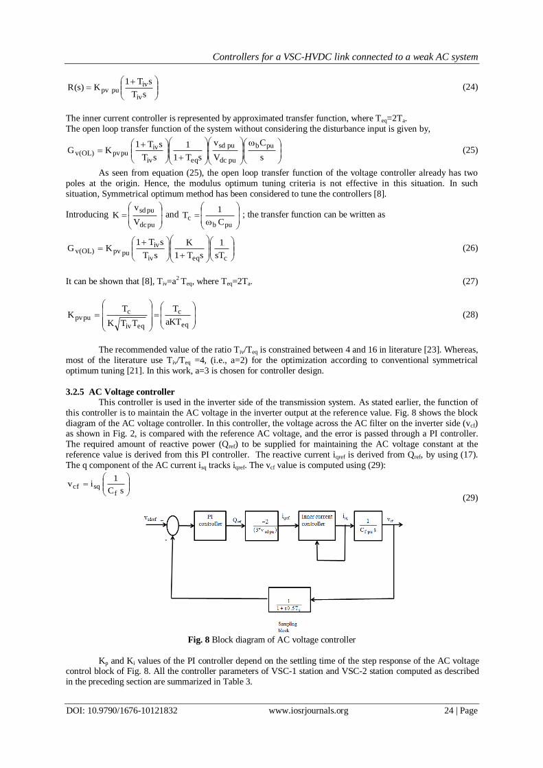
3.2.5 AC Voltage controller
This controller is used in the inverter side of the transmission system. As stated earlier, the function of
this controller is to maintain the AC voltage in the inverter output at the reference value. Fig. 8 shows the block
diagram of the AC voltage controller. In this controller, the voltage across the AC filter on the inverter side (vcf) as shown in Fig. 2, is compared with the reference AC voltage, and the error is passed through a PI controller.
The required amount of reactive power (Qref) to be supplied for maintaining the AC voltage constant at the
reference value is derived from this PI controller. The reactive current iqref is derived from Qref, by using (17).
The q component of the AC current isq tracks iqref. The vcf value is computed using (29):
sC
1iv
fsqcf
(29)
Fig. 8 Block diagram of AC voltage controller
Kp and Ki values of the PI controller depend on the settling time of the step response of the AC voltage control block of Fig. 8. All the controller parameters of VSC-1 station and VSC-2 station computed as described
in the preceding section are summarized in Table 3.
Controllers for a VSC-HVDC link connected to a weak AC system
DOI: 10.9790/1676-10121832 www.iosrjournals.org 25 | Page
Table 3. PI Controller Parameters For VSC-1 And VSC-2. Station Controller K p pu K i pu
VSC-1 Current controller 0.6118 1.755
Active power controller 0.01 45
VSC-2 Current controller 0.6118 1.755
DC voltage controller 1.738 259.40
AC voltage controller 0.00776 0.228
In the following section, the simulation results of VSC-HVDC system incorporating all the controllers
discussed in this section are presented.
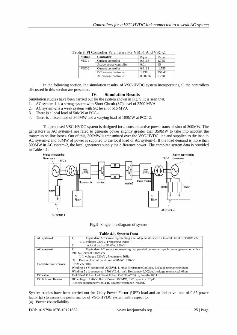
IV. Simulation Results Simulation studies have been carried out for the system shown in Fig. 9. It is seen that,
1. AC system-1 is a strong system with Short Circuit (SC) level of 3500 MVA
2. AC system-2 is a weak system with SC level of 516 MVA
3. There is a local load of 50MW at PCC-1
4. There is a fixed load of 300MW and a varying load of 100MW at PCC-2.
The proposed VSC-HVDC system is designed for a constant active power transmission of 300MW. The
generators in AC system-1 are rated to generate power slightly greater than 350MW to take into account the
transmission line losses. Out of this, 300MW is transmitted over the VSC-HVDC line and supplied to the load in AC system-2 and 50MW of power is supplied to the local load of AC system-1. If the load demand is more than
300MW in AC system-2, the local generators supply the difference power. The complete system data is provided
in Table 4.1.
Fig.9 Single line diagram of system
Table 4.1. System Data AC system-1 1) Equivalent AC source representing a set of generators with a total SC level of 3500MVA
L-L voltage: 220kV, Frequency: 50Hz
2) A local load of 50MW, 220kV
AC system-2 1) Equivalent AC source representing two parallel connected synchronous generators with a
total SC level of 516MVA
L-L voltage : 220kV , Frequency: 50Hz
2) Passive load of maximum 400MW, 220kV
Converter transformer 315MVA,50Hz
Winding 1 : Y connected, 220kV(L-L rms), Resistance:0.002pu, Leakage reactance:0.08pu
Winding 2 : Δ connected, 150kV(L-L rms), Resistance:0.002pu, Leakage reactance:0.08pu
DC cable R=1.39e-2 Ω/km, L=1.59e-4 H/km, C=2.31e-7 F/km, length=100 km
DC link and Reactor DC voltage:±150kV, Rated Power:300MW, DC capacitor: 70μF
Reactor inductance=0.034 H, Reactor resistance =0.10Ω
System studies have been carried out for Unity Power Factor (UPF) load and an inductive load of 0.85 power
factor (pf) to assess the performance of VSC-HVDC system with respect to:
(a) Power controllability
Controllers for a VSC-HVDC link connected to a weak AC system
DOI: 10.9790/1676-10121832 www.iosrjournals.org 26 | Page
(b) AC filter requirement for AC system of VSC-1
(c) DC voltage and AC voltage controllability
(d) AC filter requirement for AC system of VSC-2 For the ensuing discussion, the nomenclature is given in Appendix 1.
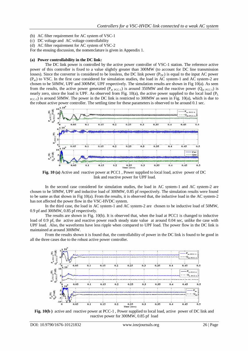
(a) Power controllability in the DC link:
The DC link power is controlled by the active power controller of VSC-1 station. The reference active
power of this controller is fixed to a value slightly greater than 300MW (to account for DC line transmission
losses). Since the converter is considered to be lossless, the DC link power (PDC) is equal to the input AC power
(Pac) to VSC. In the first case considered for simulation studies, the load in AC system-1 and AC system-2 are
chosen to be 50MW, UPF and 300MW, UPF respectively. The simulation results are shown in Fig 10(a). As seen
from the results, the active power generated (Pac PCC-1) is around 350MW and the reactive power (Qac PCC-1) is
nearly zero, since the load is UPF. As observed from Fig. 10(a), the active power supplied to the local load (PL
PCC-1) is around 50MW. The power in the DC link is restricted to 300MW as seen in Fig. 10(a), which is due to the robust active power controller. The settling time for these parameters is observed to be around 0.1 sec.
Fig. 10 (a) Active and reactive power at PCC1 , Power supplied to local load, active power of DC
link and reactive power for UPF load.
In the second case considered for simulation studies, the load in AC system-1 and AC system-2 are
chosen to be 50MW, UPF and inductive load of 300MW, 0.85 pf respectively. The simulation results were found
to be same as that shown in Fig 10(a). From the results, it is observed that, the inductive load in the AC system-2
has not affected the power flow in the VSC-HVDC system.
In the third case, the load in AC system-1 and AC system-2 are chosen to be inductive load of 50MW,
0.9 pf and 300MW, 0.85 pf respectively.
The results are shown in Fig. 10(b). It is observed that, when the load at PCC1 is changed to inductive
load of 0.9 pf, the active and reactive power reach steady state value at around 0.04 sec, unlike the case with UPF load. Also, the waveforms have less ripple when compared to UPF load. The power flow in the DC link is
maintained at around 300MW.
From the results shown it is found that, the controllability of power in the DC link is found to be good in
all the three cases due to the robust active power controller.
Fig. 10(b ) active and reactive power at PCC-1 , Power supplied to local load, active power of DC link and
reactive power for 300MW, 0.85 pf load
Controllers for a VSC-HVDC link connected to a weak AC system
DOI: 10.9790/1676-10121832 www.iosrjournals.org 27 | Page
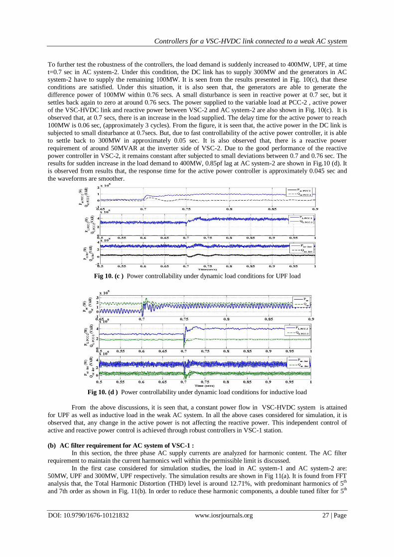
To further test the robustness of the controllers, the load demand is suddenly increased to 400MW, UPF, at time
t=0.7 sec in AC system-2. Under this condition, the DC link has to supply 300MW and the generators in AC system-2 have to supply the remaining 100MW. It is seen from the results presented in Fig. 10(c), that these
conditions are satisfied. Under this situation, it is also seen that, the generators are able to generate the
difference power of 100MW within 0.76 secs. A small disturbance is seen in reactive power at 0.7 sec, but it
settles back again to zero at around 0.76 secs. The power supplied to the variable load at PCC-2 , active power
of the VSC-HVDC link and reactive power between VSC-2 and AC system-2 are also shown in Fig. 10(c). It is
observed that, at 0.7 secs, there is an increase in the load supplied. The delay time for the active power to reach
100MW is 0.06 sec, (approximately 3 cycles). From the figure, it is seen that, the active power in the DC link is
subjected to small disturbance at 0.7secs. But, due to fast controllability of the active power controller, it is able
to settle back to 300MW in approximately 0.05 sec. It is also observed that, there is a reactive power
requirement of around 50MVAR at the inverter side of VSC-2. Due to the good performance of the reactive
power controller in VSC-2, it remains constant after subjected to small deviations between 0.7 and 0.76 sec. The results for sudden increase in the load demand to 400MW, 0.85pf lag at AC system-2 are shown in Fig.10 (d). It
is observed from results that, the response time for the active power controller is approximately 0.045 sec and
the waveforms are smoother.
Fig 10. (c ) Power controllability under dynamic load conditions for UPF load
Fig 10. (d ) Power controllability under dynamic load conditions for inductive load
From the above discussions, it is seen that, a constant power flow in VSC-HVDC system is attained
for UPF as well as inductive load in the weak AC system. In all the above cases considered for simulation, it is
observed that, any change in the active power is not affecting the reactive power. This independent control of
active and reactive power control is achieved through robust controllers in VSC-1 station.
(b) AC filter requirement for AC system of VSC-1 :
In this section, the three phase AC supply currents are analyzed for harmonic content. The AC filter
requirement to maintain the current harmonics well within the permissible limit is discussed.
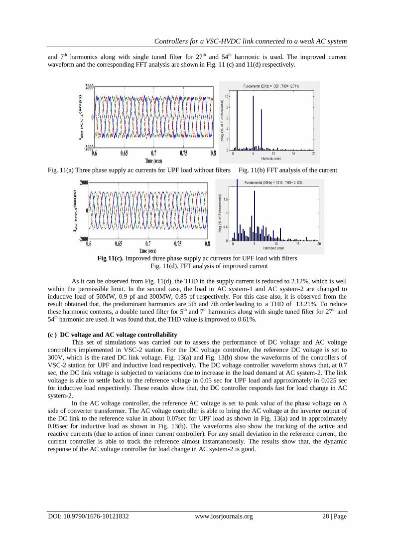
In the first case considered for simulation studies, the load in AC system-1 and AC system-2 are:
50MW, UPF and 300MW, UPF respectively. The simulation results are shown in Fig 11(a). It is found from FFT
analysis that, the Total Harmonic Distortion (THD) level is around 12.71%, with predominant harmonics of 5th
and 7th order as shown in Fig. 11(b). In order to reduce these harmonic components, a double tuned filter for 5th
Controllers for a VSC-HVDC link connected to a weak AC system
DOI: 10.9790/1676-10121832 www.iosrjournals.org 28 | Page
and 7th harmonics along with single tuned filter for 27th and 54th harmonic is used. The improved current
waveform and the corresponding FFT analysis are shown in Fig. 11 (c) and 11(d) respectively.
Fig. 11(a) Three phase supply ac currents for UPF load without filters Fig. 11(b) FFT analysis of the current
Fig 11(c). Improved three phase supply ac currents for UPF load with filters
Fig. 11(d). FFT analysis of improved current
As it can be observed from Fig. 11(d), the THD in the supply current is reduced to 2.12%, which is well
within the permissible limit. In the second case, the load in AC system-1 and AC system-2 are changed to
inductive load of 50MW, 0.9 pf and 300MW, 0.85 pf respectively. For this case also, it is observed from the result obtained that, the predominant harmonics are 5th and 7th order leading to a THD of 13.21%. To reduce
these harmonic contents, a double tuned filter for 5th and 7th harmonics along with single tuned filter for 27th and
54th harmonic are used. It was found that, the THD value is improved to 0.61%.
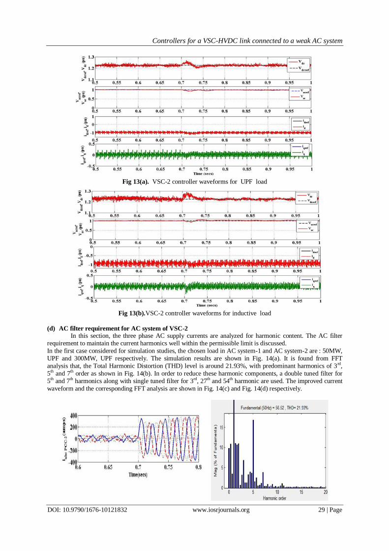
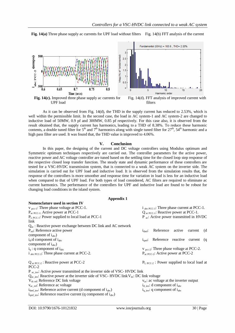
(c ) DC voltage and AC voltage controllability This set of simulations was carried out to assess the performance of DC voltage and AC voltage
controllers implemented in VSC-2 station. For the DC voltage controller, the reference DC voltage is set to
300V, which is the rated DC link voltage. Fig. 13(a) and Fig. 13(b) show the waveforms of the controllers of
VSC-2 station for UPF and inductive load respectively. The DC voltage controller waveform shows that, at 0.7
sec, the DC link voltage is subjected to variations due to increase in the load demand at AC system-2. The link
voltage is able to settle back to the reference voltage in 0.05 sec for UPF load and approximately in 0.025 sec for inductive load respectively. These results show that, the DC controller responds fast for load change in AC
system-2.
In the AC voltage controller, the reference AC voltage is set to peak value of the phase voltage on Δ
side of converter transformer. The AC voltage controller is able to bring the AC voltage at the inverter output of
the DC link to the reference value in about 0.07sec for UPF load as shown in Fig. 13(a) and in approximately
0.05sec for inductive load as shown in Fig. 13(b). The waveforms also show the tracking of the active and
reactive currents (due to action of inner current controller). For any small deviation in the reference current, the
current controller is able to track the reference almost instantaneously. The results show that, the dynamic
response of the AC voltage controller for load change in AC system-2 is good.
Controllers for a VSC-HVDC link connected to a weak AC system
DOI: 10.9790/1676-10121832 www.iosrjournals.org 29 | Page
Fig 13(a). VSC-2 controller waveforms for UPF load
Fig 13(b).VSC-2 controller waveforms for inductive load
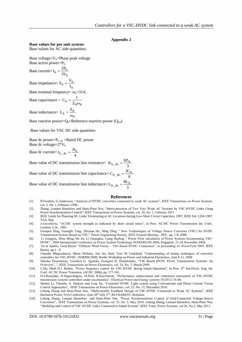
(d) AC filter requirement for AC system of VSC-2 In this section, the three phase AC supply currents are analyzed for harmonic content. The AC filter
requirement to maintain the current harmonics well within the permissible limit is discussed.
In the first case considered for simulation studies, the chosen load in AC system-1 and AC system-2 are : 50MW,
UPF and 300MW, UPF respectively. The simulation results are shown in Fig. 14(a). It is found from FFT
analysis that, the Total Harmonic Distortion (THD) level is around 21.93%, with predominant harmonics of 3rd,
5th and 7
th order as shown in Fig. 14(b). In order to reduce these harmonic components, a double tuned filter for
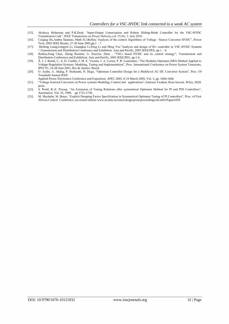
5th and 7th harmonics along with single tuned filter for 3rd, 27th and 54th harmonic are used. The improved current
waveform and the corresponding FFT analysis are shown in Fig. 14(c) and Fig. 14(d) respectively.
Controllers for a VSC-HVDC link connected to a weak AC system
DOI: 10.9790/1676-10121832 www.iosrjournals.org 30 | Page
Fig. 14(a) Three phase supply ac currents for UPF load without filters Fig. 14(b) FFT analysis of the current
Fig. 14(c). Improved three phase supply ac currents for Fig. 14(d). FFT analysis of improved current with
UPF load filters
As it can be observed from Fig. 14(d), the THD in the supply current has reduced to 2.53%, which is
well within the permissible limit. In the second case, the load in AC system-1 and AC system-2 are changed to
inductive load of 50MW, 0.9 pf and 300MW, 0.85 pf respectively. For this case also, it is observed from the
result obtained that, the supply current has harmonics, leading to a THD of 8.38%. To reduce these harmonic contents, a double tuned filter for 5th and 7th harmonics along with single tuned filter for 27th, 54th harmonic and a
high pass filter are used. It was found that, the THD value is improved to 4.06%.
V. Conclusion
In this paper, the designing of the current and DC voltage controllers using Modulus optimum and
Symmetric optimum techniques respectively are carried out. The controller parameters for the active power,
reactive power and AC voltage controller are tuned based on the settling time for the closed loop step response of
the respective closed loop transfer function. The steady state and dynamic performance of these controllers are
tested for a VSC-HVDC transmission system, that is connected to a weak AC system on the inverter side. The simulation is carried out for UPF load and inductive load. It is observed from the simulation results that, the
response of the controllers is more smoother and response time for variation in load is less for an inductive load
when compared to that of UPF load. For both types of load considered, AC filters are required to eliminate ac
current harmonics. The performance of the controllers for UPF and inductive load are found to be robust for
changing load conditions in the island system.
Appendix 1
Nomenclature used in section IV
v pcc-1: Three phase voltage at PCC-1. i abc PCC-1: Three phase current at PCC-1.
Pac PCC-1: Active power at PCC-1 Q ac PCC-1: Reactive power at PCC-1.
PL PCC-1: Power supplied to local load at PCC-1 P ac: Active power transmitted in HVDC link
Qac : Reactive power exchange between DC link and AC network
Pref: Reference active power idref: Reference active current (d
component of iabc)
id:d component of iabc iqref: Reference reactive current (q
component of iabc)
iq : q component of iabc v pcc-2: Three phase voltage at PCC-2.
i abc PCC-2: Three phase current at PCC-2. Pac PCC-2: Active power at PCC-2
Q ac PCC-2 : Reactive power at PCC-2 PL PCC-2 : Power supplied to local load at
PCC-2 P ac_inv: Active power transmitted at the inverter side of VSC- HVDC link
Qac_inv: Reactive power at the inverter side of VSC- HVDC link Vdc: DC link voltage
Vdc ref: Reference DC link voltage vac: ac voltage at the inverter output
vac_ref: Reference ac voltage id_inv: d component of iabc
idref_inv: Reference active current (d component of iabc) iq_inv: q component of iabc
iqref_inv: Reference reactive current (q component of iabc)
Controllers for a VSC-HVDC link connected to a weak AC system
DOI: 10.9790/1676-10121832 www.iosrjournals.org 31 | Page
Appendix 2
Base values for per unit system: Base values for AC side quantities:
Base voltage=Vb=Phase peak voltage
Base active power=Pb
Base current=b
bb
V3
P2I
Base impedance=b
bb
I
VZ
Base nominal frequency= wb=314;
Base capacitance = bb
bZ
1C
Base inductance= b
bb
ZL
Base reactive power=Qb=Reference reactive power (Qref)
Base values for VSC DC side quantities
Base dc power=Pb_dc =Rated DC power
Base dc voltage=2*Vb
Base dc current=4
I3I b
dc_b
Base value of DC transmission line resistance= 3
Z8R b
dc_b
Base value of DC transmission line capacitance=8
C3C b
dc_b
Base value of DC transmission line inductance=3
L8L b
dc_b
References [1]. B.Frankén, G.Andersson, “Analysis of HVDC converters connected to weak AC systems”, IEEE Transactions on Power Systems,
vol. 5, No. 1, February 1990.
[2]. Zhang, Lennart Harnefors and Hans-Peter Nee, “Interconnection of Two Very Weak AC Systems by VSC-HVDC Links Using
Power-Synchronization Control”, IEEE Transactions on Power Systems, vol. 26, No. 1, February 2011.
[3]. IEEE Guide for Planning DC Links Terminating at AC Locations having Low Short Circuit Capacities, 1997, IEEE Std. 1204-1997,
Tech. Rep
[4]. A.Gavrilovic, “AC/DC system strength as indicated by short circuit ratios”, in Proc. AC/DC Power Transmission Int. Conf.,
London, U.K., 1991.
[5]. Guanjun Ding, Guangfu Tang, Zhiyuan He, Ming Ding “ New Technologies of Voltage Source Converter (VSC) for HVDC
Transmission System Based on VSC.” Power Engineering Society, IEEE General Meeting - PES , pp. 1-8, 2008
[6]. Li Gengyin, Zhou Ming, He Jie, Li Guangkai, Liang Haifeng “ Power Flow calculation of Power Systems Incorporating VSC -
HVDC”, 2004 International Conference on Power System Technology-POWERCON 2004, Singapore, 21-24 November 2004.
[7]. Ervin Spahic, Gerd Balzer “Offshore Wind Farms – VSC-based HVDC Connection”, in proceeding of: PowerTech 2005, IEEE
Russia, pp.1 - 6
[8]. Chandra Bhajracharya, Marta Molinas, Jon Are Suul, Tore M Undeland, “Understanding of tuning techniques of converter
controllers for VSC-HVDC. NORPIE/2008, Nordic Workshop on Power and Industrial Electronics, June 9-11, 2008
[9]. Nikolas Flourentzou, Vassilios G. Agelidis, Georgios D. Demetriades, “VSC-Based HVDC Power Transmission Systems: An
Overview”, ”, IEEE Transactions on Power Electronics, vol. 24, No. 3, March 2009.
[10]. C.Du, Math H.J. Bollen, “Power frequency control for VSC-HVDC during Island Operation”, in Proc. 8th Inst.Electr. Eng. Int.
Conf. AC DC Power Transmiss. (ACDC 2006), pp. 177-181.
[11]. H.S.Ramadan, H.Siguerdidjane, M.Petit, R.Kaczmarek, “Performance enhancement and robustness assessment of VSC-HVDC
transmission systems controllers under uncertainties”, Electrical Power and Energy systems 35(2012) 34-46.
[12]. Shuhui Li, Timothy A. Haskew and Ling Xu, “Controlof HVDC Light system using Conventional and Direct Current Vector
Control Approaches”, IEEE Transactions on Power Electronics, vol. 25, No. 12, December 2010.
[13]. Lidong Zhang and Hans-Peter Nee, “Multivariable Feedback Design of VSC-HVDC Connected to Weak AC Systems”, IEEE
Bucharest Power Tech Conference, June 28th-July 2
nd, BUCHAREST, Romania.
[14]. Lidong Zhang, Lennart Harnefors and Hans-Peter Nee, “Power Synchronization Control of Grid-Connected Voltage-Source
Converters”, IEEE Transactions on Power Eystems, vol. 25, No. 2, May 2010. Lidong Zhang, Lennart Harnefors, Hans-Peter Nee,
“Modeling and Control of VSC-HVDC Links Connected to Island Systems”,IEEE Trans. Power Systems, vol.26, No.2, May 2011.
Controllers for a VSC-HVDC link connected to a weak AC system
DOI: 10.9790/1676-10121832 www.iosrjournals.org 32 | Page
[15]. Akshaya Moharana and P.K.Dash, “Input-Output Linearization and Robust Sliding-Mode Controller for the VSC-HVDC
Transmission Link”, IEEE Transactions on Power Delivery,vol. 25,No. 3, July 2010.
[16]. Cuiqing Du,Ambra Sannino, Math H.J.Bollen,”Analysis of the control Algorithms of Voltage –Source Converter HVDC”, Power
Tech, 2005 IEEE Russia, 27-30 June 2005,pp.1 – 7.
[17]. Heifeng Liang,Gengyin Li, Guangkai Li,Peng Li and Ming Yin,”Analysis and design of H∞ controller in VSC-HVDC Systems
“,Transmission and Distribution Conference and Exhibition: Asia and Pacific, 2005 IEEE/PES, pp.1 – 6.
[18]. Ruihua,Song Chao, Zheng Ruomei, Li Xiaoxin, Zhou , “VSCs based HVDC and its control strategy”, Transmission and
Distribution Conference and Exhibition: Asia and Pacific, 2005 IEEE/PES, pp.1-6.
[19]. Â. J. J. Rezek, C. A. D. Coelho, J. M. E. Vicente, J. A. Cortez, P. R. Laurentino, “The Modulus Optimum (MO) Method Applied to
Voltage Regulation Systems: Modeling, Tuning and Implementation”, Proc. International Conference on Power System Transients,
IPST’01, 24-28 June 2001, Rio de Janeiro, Brazil.
[20]. O. Aydin, A. Akdag, P. Stefanutti, N. Hugo, “Optimum Controller Design for a Multilevel AC-DC Converter System”, Proc. Of
Twentieth Annual IEEE
Applied Power Electronics Conference and Exposition, APEC 2005, 6-10 March 2005, Vol. 3, pp. 1660-1666
[21]. “Voltage Sourced Converters in Power systems Modeling, Control and applications”,Amirsen Yazdani, Reza Iravani, Wiley, IEEE
press.
[22]. S. Preitl, R.-E. Precup, “An Extension of Tuning Relations after symmetrical Optimum Method for PI and PID Controllers”,
Automatica, Vol. 35, 1999, pp 1731-1736.
[23]. M. Machaba, M. Braae, “Explicit Damping Factor Specification in Symmetrical Optimum Tuning of PI Controllers”, Proc. of First
African Control Conference, (accessed online) www.nt.ntnu.no/users/skoge/prost/proceedings/afcon03/Papers/050
Recommended