An Approved Continuing Education Provider
PDHonline Course M488 (4 PDH)
Control Valve Basics – Sizing & Selection
A. Bhatia, B.E.
2013
PDH Online | PDH Center
5272 Meadow Estates Drive
Fairfax, VA 22030-6658
Phone & Fax: 703-988-0088
www.PDHonline.org
www.PDHcenter.com

www.PDHcenter.com PDHonline Course M488 www.PDHonline.org
©2013 A. Bhatia Page 2 of 62
Control Valve Basics – Sizing & Selection
A. Bhatia, B.E.
Introduction
A control valve is a power operated device capable of modulating flow at varying degrees
between minimal flow and full capacity in response to a signal from the controlling system.
Control valves may be broadly classified by their function as “on-off” type or “flow regulating”
type.
A control valve is comprised of an actuator mechanism that is capable of changing the position
of flow controlling element in the valve. The valve modulates flow through movement of a
valve plug in relation to the port(s) located within the valve body. The valve plug is attached to
a valve stem, which, in turn, is connected to the actuator. The actuator, which can be
pneumatically or electrically operated, directs the movement of the stem as dictated by the
external control device. Actuator responds to an external signal, which usually comes from a
controller. The controller and valve together form a basic control loop.
There are many types of valves available – each having their advantages and limitations. The
basic requirements and selection depend on their ability to perform specific functions such as:
1. Ability to throttle or control the rate of flow;
2. Lack of turbulence or resistance to flow when fully open. Turbulence reduces head
pressure;
3. Quick opening and closing mechanism. Rapid response is many times needed in
emergency/safety;
4. Tight shut off. Prevent leaks against high pressure;
5. Ability to allow flow in one direction only - prevent return;
6. Opening at a pre-set pressure. Procedure control to prevent equipment damage;
7. Ability to handle abrasive fluids. Hardened material prevents rapid wear.
This course will discuss the selection process and provide the basic principles of sizing the
control valves.

www.PDHcenter.com PDHonline Course M488 www.PDHonline.org
©2013 A. Bhatia Page 3 of 62
BASIC VALVE TYPES
Valves are available with a wide variety of valve bodies in various styles, materials,
connections and sizes. Selection is primarily dependent upon on the service conditions, the
task and the load characteristics of the application. The most common types are ball valves,
butterfly valves, globe valves and gate valves.
Ball Valves:
Ball valves are a quick opening valve that gives a tight shutoff. When fully open, the valve
creates little turbulence or resistance to flow. The valve stem rotates a ball which contains an
opening. The ball opening can be positioned in the fully open or fully closed position but must
not be used to throttle flow as any abrasive wear to the ball will cause leakage when the valve
is closed.
Ball valves are considered high recovery valves, meaning a low pressure drop and relatively
high flow capacity.
Best Suited Control: Quick opening, linear
Recommended Uses:
Fully open/closed, limited-throttling
Higher temperature fluids
Applications:
Ball valves are excellent in chemical applications, including the most challenging
services (e.g. dry chlorine, hydrofluoric acid, oxygen).
General sizes available are 1/2 - 12".
www.PDHcenter.com PDHonline Course M488 www.PDHonline.org
©2013 A. Bhatia Page 4 of 62
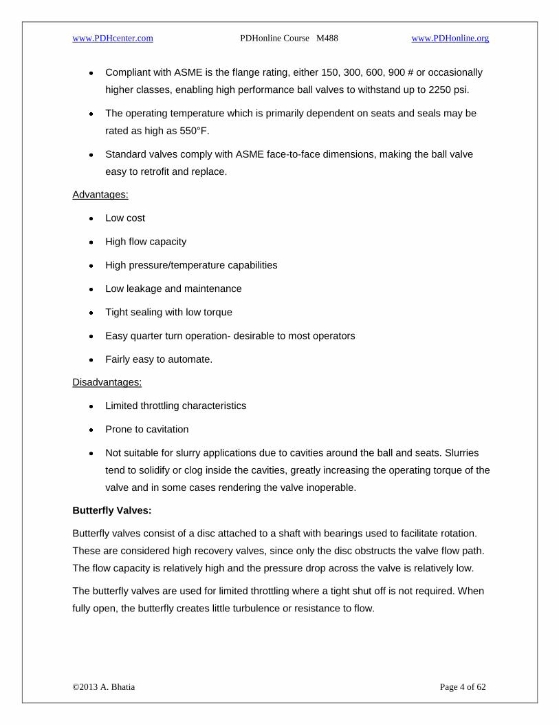
Compliant with ASME is the flange rating, either 150, 300, 600, 900 # or occasionally
higher classes, enabling high performance ball valves to withstand up to 2250 psi.
The operating temperature which is primarily dependent on seats and seals may be
rated as high as 550°F.
Standard valves comply with ASME face-to-face dimensions, making the ball valve
easy to retrofit and replace.
Advantages:
Low cost
High flow capacity
High pressure/temperature capabilities
Low leakage and maintenance
Tight sealing with low torque
Easy quarter turn operation- desirable to most operators
Fairly easy to automate.
Disadvantages:
Limited throttling characteristics
Prone to cavitation
Not suitable for slurry applications due to cavities around the ball and seats. Slurries
tend to solidify or clog inside the cavities, greatly increasing the operating torque of the
valve and in some cases rendering the valve inoperable.
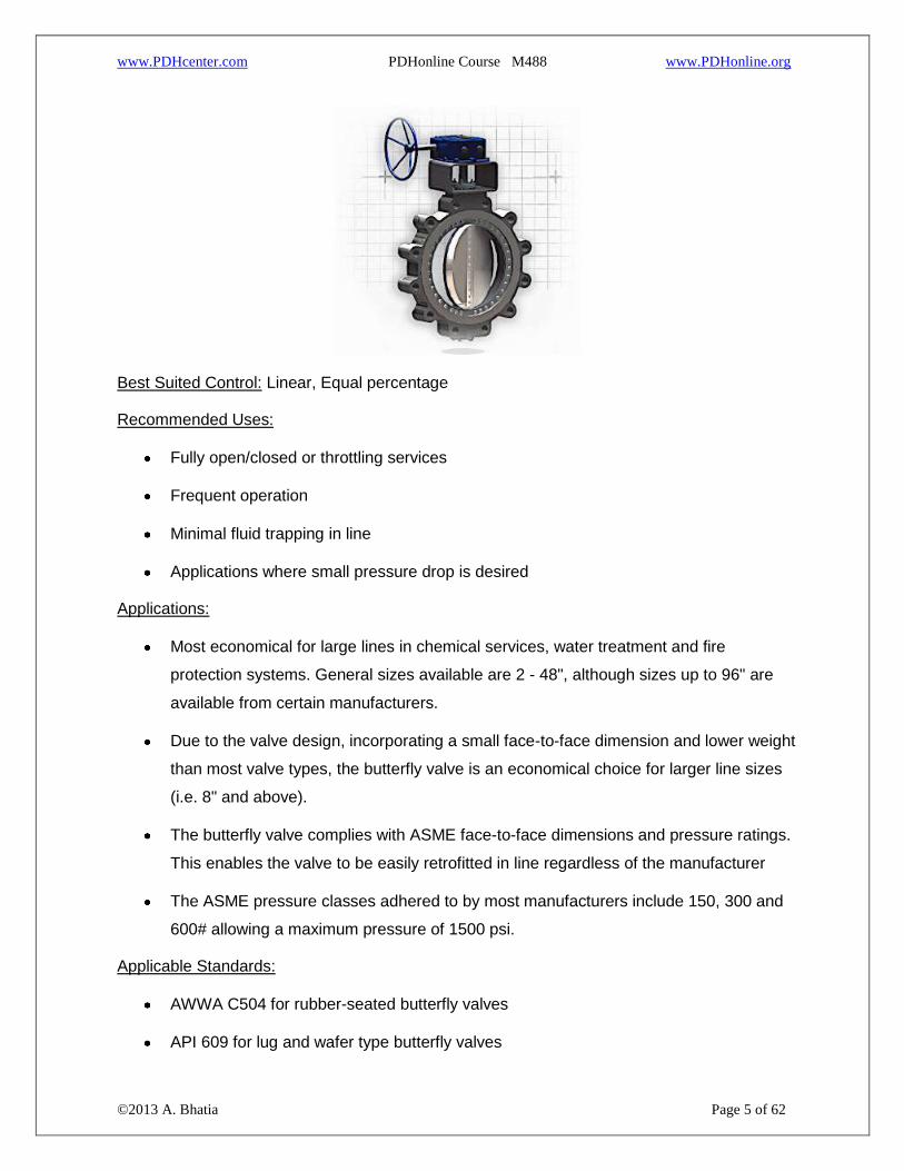
Butterfly Valves:
Butterfly valves consist of a disc attached to a shaft with bearings used to facilitate rotation.
These are considered high recovery valves, since only the disc obstructs the valve flow path.
The flow capacity is relatively high and the pressure drop across the valve is relatively low.
The butterfly valves are used for limited throttling where a tight shut off is not required. When
fully open, the butterfly creates little turbulence or resistance to flow.
www.PDHcenter.com PDHonline Course M488 www.PDHonline.org
©2013 A. Bhatia Page 5 of 62
Best Suited Control: Linear, Equal percentage
Recommended Uses:
Fully open/closed or throttling services
Frequent operation
Minimal fluid trapping in line
Applications where small pressure drop is desired
Applications:
Most economical for large lines in chemical services, water treatment and fire
protection systems. General sizes available are 2 - 48", although sizes up to 96" are
available from certain manufacturers.
Due to the valve design, incorporating a small face-to-face dimension and lower weight
than most valve types, the butterfly valve is an economical choice for larger line sizes
(i.e. 8" and above).
The butterfly valve complies with ASME face-to-face dimensions and pressure ratings.
This enables the valve to be easily retrofitted in line regardless of the manufacturer
The ASME pressure classes adhered to by most manufacturers include 150, 300 and
600# allowing a maximum pressure of 1500 psi.
Applicable Standards:
AWWA C504 for rubber-seated butterfly valves
API 609 for lug and wafer type butterfly valves

www.PDHcenter.com PDHonline Course M488 www.PDHonline.org
©2013 A. Bhatia Page 6 of 62
MSS SP-69 for general butterfly valves
UL 1091 for safety butterfly valves for fire protection services
Advantages:
Low cost and maintenance
High capacity
Good flow control
Low pressure drop
Disadvantages:
High torque required for control
Prone to cavitation at lower flows
Lack of cleanliness and inability to handle slurry applications.
Generally not rated as bubble tight, and the cavities and leak paths around the disc
stem are potential entrapments for fluids and slurries. Some high performance butterfly
valves meeting ASME class VI leakage ratings are however available on demand.
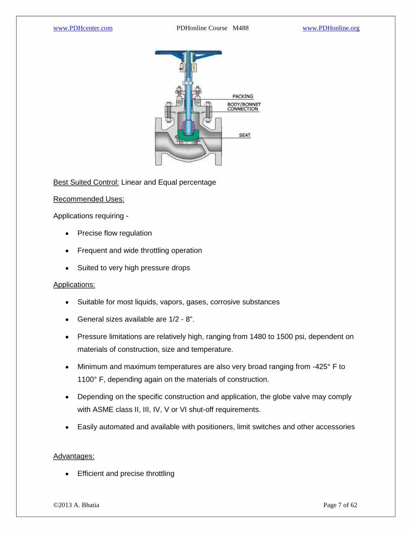
Globe Valves:
Globe valves consist of a movable disk-type element and a stationary ring seat in a generally
spherical body. The valve stem moves a globe plug relative to the valve seat. The globe plug
can be at any position between fully opened and fully closed to control flow through the valve.
The globe and seat construction gives the valve good flow regulation characteristics. Turbulent
flow past the seat and plug when the valve is open results in a relatively high pressure drop,
limited flow capacity and low recovery.
www.PDHcenter.com PDHonline Course M488 www.PDHonline.org
©2013 A. Bhatia Page 7 of 62
Best Suited Control: Linear and Equal percentage
Recommended Uses:
Applications requiring -
Precise flow regulation
Frequent and wide throttling operation
Suited to very high pressure drops
Applications:
Suitable for most liquids, vapors, gases, corrosive substances
General sizes available are 1/2 - 8".
Pressure limitations are relatively high, ranging from 1480 to 1500 psi, dependent on
materials of construction, size and temperature.
Minimum and maximum temperatures are also very broad ranging from -425° F to
1100° F, depending again on the materials of construction.
Depending on the specific construction and application, the globe valve may comply
with ASME class II, III, IV, V or VI shut-off requirements.
Easily automated and available with positioners, limit switches and other accessories
Advantages:
Efficient and precise throttling

www.PDHcenter.com PDHonline Course M488 www.PDHonline.org
©2013 A. Bhatia Page 8 of 62
Accurate flow control
Disadvantages:
Low recovery and relatively low coefficient of flow (Cv).
High pressure drop, higher pump capacity and system wear
More expensive than other valves
The sealing device is a plug that offers limited shut-off capabilities, not always meeting
bubble tight requirements.
Gate valve:
Gate valves use linear type of stem motion for opening and closing of valve. These valves use
parallel or wedge shaped discs as closure member that provide tight sealing.
Best Suited Control: Quick Opening
Recommended Uses:
Fully open/closed, non-throttling
Infrequent operation
Minimal fluid trapping in line
Applications:
Suitable for oil, gas, air, heavy liquids, steam, noncondensing gases, abrasive and
corrosive liquids

www.PDHcenter.com PDHonline Course M488 www.PDHonline.org
©2013 A. Bhatia Page 9 of 62
Sizes available range from standard cast configurations as small as 2" to special
fabricated valves exceeding 100".
Standard cast configurations have ASME 125/150 bolting patterns and are rated at 150
psi.
Advantages:
High capacity
Tight shutoff
Low cost
Little resistance to flow
Ability to cut through slurries, scale and surface build ups
Provide unobstructed flow paths that not only provide high flow capacity (Cv), but even
allows slurry, large objects, rocks and items routinely found in mining processes to
safely pass through the valve.
Disadvantages:
Poor control
Cavitate at low pressure drops
Cannot be used for throttling
Relatively low pressure limitation - general pressure limitations are 150 psi maximum.
Refer to the summary table at the end of this section to check more valves and their
characteristics.
ACTUATORS
A valve actuator is a device that produces force to open or close the valve utilizing a power
source. This source of power can be manual (hand, gear, chain-wheel, lever etc.) or can be
electric, hydraulic or pneumatic.
www.PDHcenter.com PDHonline Course M488 www.PDHonline.org
©2013 A. Bhatia Page 10 of 62
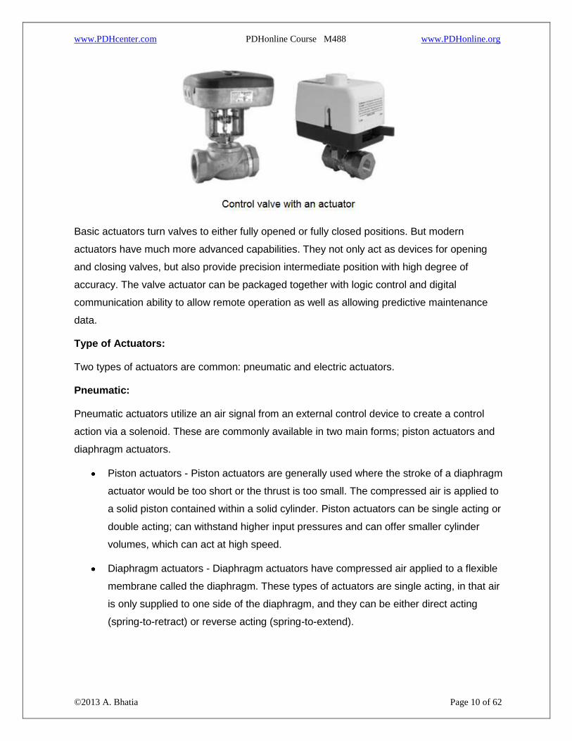
Basic actuators turn valves to either fully opened or fully closed positions. But modern
actuators have much more advanced capabilities. They not only act as devices for opening
and closing valves, but also provide precision intermediate position with high degree of
accuracy. The valve actuator can be packaged together with logic control and digital
communication ability to allow remote operation as well as allowing predictive maintenance
data.
Type of Actuators:
Two types of actuators are common: pneumatic and electric actuators.
Pneumatic:
Pneumatic actuators utilize an air signal from an external control device to create a control
action via a solenoid. These are commonly available in two main forms; piston actuators and
diaphragm actuators.
Piston actuators - Piston actuators are generally used where the stroke of a diaphragm
actuator would be too short or the thrust is too small. The compressed air is applied to
a solid piston contained within a solid cylinder. Piston actuators can be single acting or
double acting; can withstand higher input pressures and can offer smaller cylinder
volumes, which can act at high speed.
Diaphragm actuators - Diaphragm actuators have compressed air applied to a flexible
membrane called the diaphragm. These types of actuators are single acting, in that air
is only supplied to one side of the diaphragm, and they can be either direct acting
(spring-to-retract) or reverse acting (spring-to-extend).

www.PDHcenter.com PDHonline Course M488 www.PDHonline.org
©2013 A. Bhatia Page 11 of 62
Their range of applications is enormous. For example, the smallest can deliver a few inch
pounds of torque where the largest are capable of producing in excess of a million inch
pounds of torque.
Electric:
Electric actuators are motor driven devices that utilize an electrical input signal to generate a
motor shaft rotation. This rotation is, in turn, translated by the unit’s linkage into a linear
motion, which drives the valve stem and plug assembly for flow modulation. In case of electric
signal failure, these actuators can be specified to fail in the stem-out, stem-in, or last position.
Commonly used motors for electric actuators include steppers and servos.
A step motor uses gears with increments in a range of 5,000 to 10,000 @ 90 degree
rotation for accurate positioning at lower speeds. The disadvantage is that steppers
may lose synchronization with the controller when employed open loop without an
encoder or if they are undersized for an application.
Servos, by definition, are closed loop and provide superior performance at high
speeds, albeit at a higher cost. High precision screws and anti-backlash mechanics
provide accuracies to ten-thousandths of an inch. Standard precisions with standard
components range from a few hundredths to a few thousandths of an inch.
Brush DC motors and AC motors are sometimes used with limit switches when positioning
accuracy is less critical. The motor is connected to a gear or thread that creates thrust to move
the valve. To protect the valve the torque sensing mechanism of the actuator turns off the
electric motor when a safe torque level is exceeded. Position switches are utilized to indicate
the open and closed position of the valve. Typically a declutching mechanism and hand wheel
are included so that the valve can be operated manually should a power failure occur.
Pneumatic v/s Electric Actuators
The major difference between pneumatic and electronic actuators is the speed of operation.
The two technologies are so different that one cannot be a drop-in replacement for the other.
Each has inherent advantages and disadvantages.
Advantages of Pneumatic Actuators
The biggest advantage of the pneumatic actuators is their failsafe action. By design of
the compressed spring, the engineer can determine if the valve will fail closed or open,
depending on the safety of the process.

www.PDHcenter.com PDHonline Course M488 www.PDHonline.org
©2013 A. Bhatia Page 12 of 62
Provide high force and speed, which are easily adjustable and are independent of each
other
Have a delayed response which makes them ideal for being resilient against small
upsets in pressure changes of the source.
Pneumatic actuators are most economical when the scale of deployment matches the
capacity of the compressor.
Provide inherent safety and are ideal for hazardous and explosive environment.
Low component cost and smaller footprint. Prices for non-repairable, rod-type cylinders
range from $15 to $250 depending on body diameter, stroke and options.
Limitations of Pneumatic Actuators
Maintenance and operating costs can be high, especially if a serious effort has not
been made to quantify and minimize the costs. Maintenance costs include replacement
cylinder costs, plugging air-line leakages and the operating costs include the cost of
compressed air - electricity for the compressor.
Electric actuators
Advantages
Provide precise control and positioning in comparison to pneumatic actuators.
Response time is essentially instantaneous.
High degree of stability.
Help adapt machines to flexible processes.
Low operating cost. Controllers and drivers low voltage circuitry consumes power to a
far lesser degree.
Disadvantages
The primary disadvantage of an electric actuator is that, should a power failure occur,
the valve remains in the last position and the fail-safe position cannot be obtained
easily unless there is a convenient source of stored electrical energy.
Higher cost than pneumatic actuators. The total cost ranges from $800 to $3,000 and
up. High component costs often deter the use of electric actuators because savings in
www.PDHcenter.com PDHonline Course M488 www.PDHonline.org
©2013 A. Bhatia Page 13 of 62
operating costs compared to pneumatics are often not adequately considered or are
outright ignored.
The actuator needs to be in an environment that is rendered safe. Generally not
recommended for flammable atmospheres.
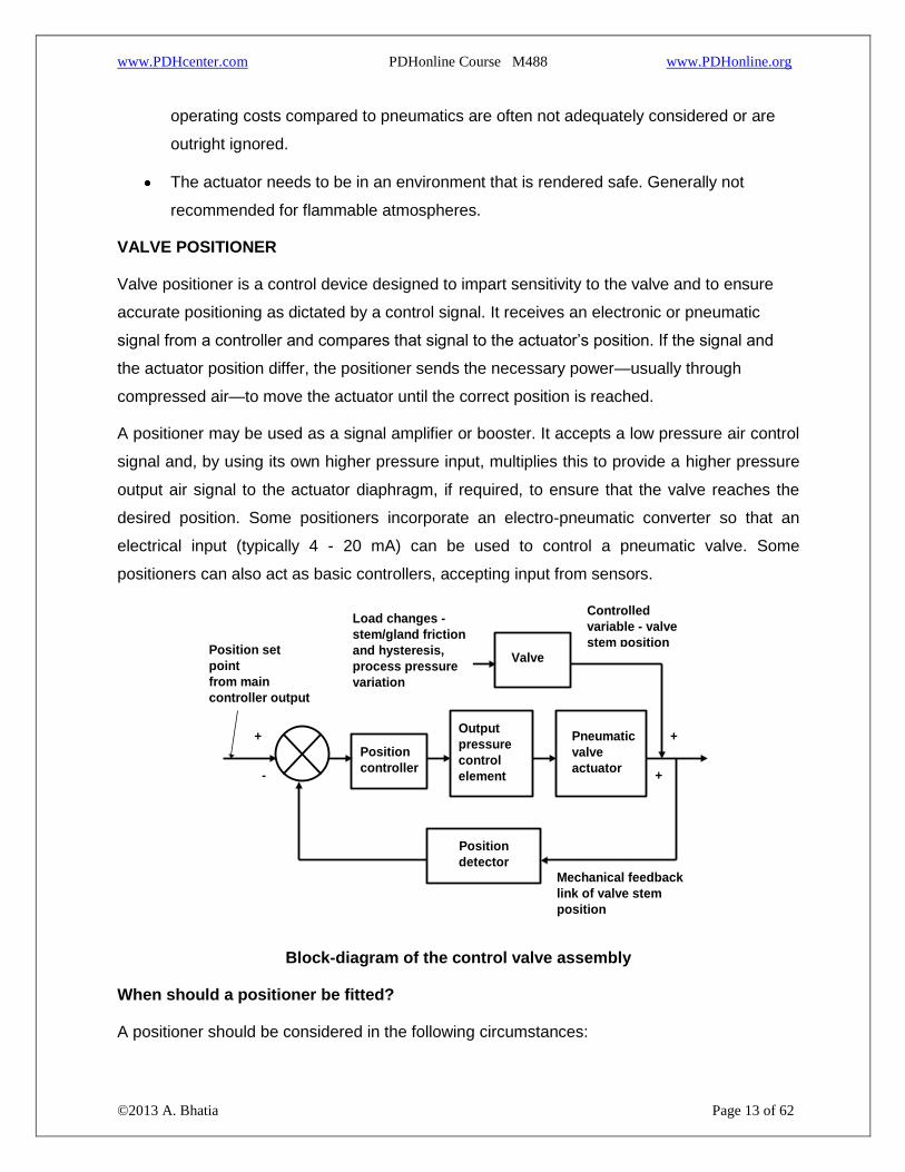
VALVE POSITIONER
Valve positioner is a control device designed to impart sensitivity to the valve and to ensure
accurate positioning as dictated by a control signal. It receives an electronic or pneumatic
signal from a controller and compares that signal to the actuator’s position. If the signal and
the actuator position differ, the positioner sends the necessary power—usually through
compressed air—to move the actuator until the correct position is reached.
A positioner may be used as a signal amplifier or booster. It accepts a low pressure air control
signal and, by using its own higher pressure input, multiplies this to provide a higher pressure
output air signal to the actuator diaphragm, if required, to ensure that the valve reaches the
desired position. Some positioners incorporate an electro-pneumatic converter so that an
electrical input (typically 4 - 20 mA) can be used to control a pneumatic valve. Some
positioners can also act as basic controllers, accepting input from sensors.
Output
pressure
control
element
Pneumatic
valve
actuator
Position
detector
-
+
Position set
point
from main
controller output
Position
controller
Valve
Mechanical feedback
link of valve stem
position
Load changes -
stem/gland friction
and hysteresis,
process pressure
variation
Controlled
variable - valve
stem position
+
+
Block-diagram of the control valve assembly
When should a positioner be fitted?
A positioner should be considered in the following circumstances:

www.PDHcenter.com PDHonline Course M488 www.PDHonline.org
©2013 A. Bhatia Page 14 of 62
When accurate valve positioning is required;
To speed up the valve response. The positioner uses higher pressure and greater air
flow to adjust the valve position;
To increase the pressure that a particular actuator and valve can close against. (To act
as an amplifier);
When the valve pressure drop at the maximum operating flowrate, exceeds 5 bar for
single seated valves or 10 bar for double seated valves;
To linearize a non-linear actuator;
Where varying differential pressures within the fluid would cause the plug position to
vary;
When controlling with wide throttling range;
Valves handling sludge or solids in suspension.
Furnish positioners for all control valves in critical service and where the variable, such as
flow, has to be closely controlled. Specify that the positioner be furnished with the control valve
or damper instead of separate procurement.
CONTROLLING THE VALVE
A control loop consists of a sensing element, a controller and the final control element — the
valve and its actuator.
The sensing element transmits a signal to a single controller or a distributed control system
(DCS). The controller compares the signal with the setpoint, and then makes any needed
corrections by sending a signal to the control valve. The correction is measured and verified by
the sensing element, completing the loop. The I/P transducer changes an electronic signal into
www.PDHcenter.com PDHonline Course M488 www.PDHonline.org
©2013 A. Bhatia Page 15 of 62
one that is pneumatic. A control valve should react instantaneously to any change in the
signal. To be effective, a valve should: operate over a wide range of flows (have a wide
rangeability); accurately respond to any signal across its operating range; exhibit little dead
time or hysteresis; react to incremental adjustments from the controller (resolution); and
respond with the required speed (stroking speed).
A fast response may not be suitable for all applications. For example, a quick or sudden
reduction in the bore of a valve in a pipeline may be harmful, causing a shock wave. A valve’s
ability to control flow depends upon the quality of its actuator. A positioner may be added to
obtain a more-precise response and tighter control. The quality of any control device can be
quantified in terms of its gain, time constant and dead-time lag. Of these, the gain is the most
important for a control valve. Gain is the ratio of the percentage change in a process variable
to the percentage change of the valve travel. Gain depends upon the valve characteristics and
process conditions.
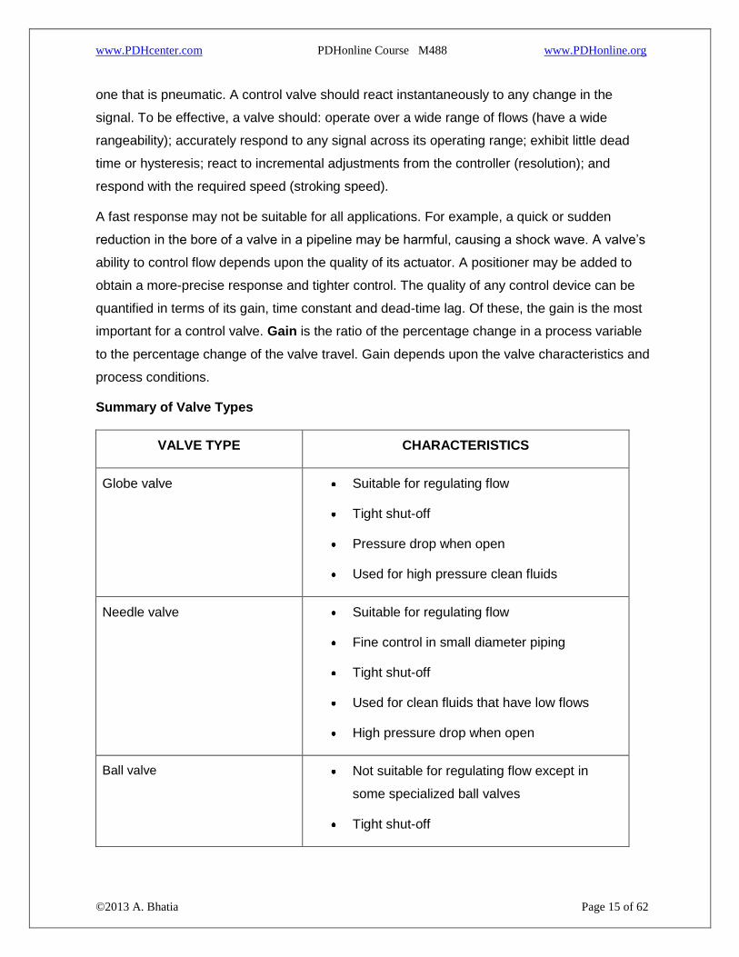
Summary of Valve Types
VALVE TYPE CHARACTERISTICS
Globe valve Suitable for regulating flow
Tight shut-off
Pressure drop when open
Used for high pressure clean fluids
Needle valve Suitable for regulating flow
Fine control in small diameter piping
Tight shut-off
Used for clean fluids that have low flows
High pressure drop when open
Ball valve Not suitable for regulating flow except in
some specialized ball valves
Tight shut-off

www.PDHcenter.com PDHonline Course M488 www.PDHonline.org
©2013 A. Bhatia Page 16 of 62
Low pressure drop when open
Used for gas, liquids or slurries
Butterfly valve Suitable for regulating flow
Not suitable for tight shut-off
Low pressure drop when open
Used for low line pressure and large pipe line
diameters
Wide range of service; gas, liquids and
slurries
Gate valve Not suitable for flow regulation, only suitable
for on or off
Tight shut-off
Low pressure drop when open
Diaphragm valve Suitable for on/off or narrow range throttling
control
Tight shut-off
Low pressure drop when open
Used for corrosive fluids and slurries
Plug valve Suitable for regulating flow
Tight shut-off
Quick opening
High pressure drop when open
Non-return valve Allow flow in one direction only
Self closing
Low pressure drop when open

www.PDHcenter.com PDHonline Course M488 www.PDHonline.org
©2013 A. Bhatia Page 17 of 62
Not suitable for reciprocating pump discharge
Pressure relief valve Opens at pre-determined pressure level

www.PDHcenter.com PDHonline Course M488 www.PDHonline.org
©2013 A. Bhatia Page 18 of 62
SECTION -2: CONTROL VALVE FUNDAMENTALS
The flow regulation in a valve is accomplished by the varying resistance as the valve is stroked
i.e. its effective cross sectional area is changed. As the fluid moves from the piping into the
smaller diameter orifice of the valve, its velocity increases to enable mass flow through the
valve. The energy needed to increase the velocity comes at the expense of the pressure, so
the point of highest velocity is also the point of lowest pressure (smallest cross section). The
point where the pressure is at the lowest is called “vena contracta”. To display the general
behavior of flow through a control valve, the valve is simplified to an orifice in a pipeline as
shown in figure below:
As the liquid passes the point of greatest restriction (vena contracta); its velocity reaches a
maximum and its pressure falls to a minimum. Hence we would expect highest velocity at the
internal to the valve than on upstream and downstream. Beyond the vena contracta, the fluid’s
velocity will decrease as the diameter of piping increases. This allows for some pressure
recovery as the energy that was imparted as velocity is now partially converted back into
pressure (refer pressure-velocity profile below).

www.PDHcenter.com PDHonline Course M488 www.PDHonline.org
©2013 A. Bhatia Page 19 of 62
It is important to understand how the pressure-velocity conditions change as the fluid passes
through the restriction. This is best described by the continuity equation:
V1 * A1 = V2 * A2
Where:
V = mean velocity and
A = flow area.
Subscript 1 refers to upstream conditions
Subscript 2 refer to downstream conditions
The equation shows that the velocity and hence the pressure can be changed by adjusting the
valve opening (area). With this introduction, we will jump straight to control valve basics and
the readers interested in further reading should read the basic principles of hydraulics.
Control Valve Capacity - Cv
For sizing a control valve we are interested in knowing how much flow we can get through the
valve for any given opening of the valve and for any given pressure differential. The
relationship between pressure drop and flow rate through a valve is conveniently expressed by
a flow coefficient (Cv).
What is Flow Coefficient (Cv)?

www.PDHcenter.com PDHonline Course M488 www.PDHonline.org
©2013 A. Bhatia Page 20 of 62
Flow coefficient (Cv) is defined as the number of gallons per minute (gpm) at 60°F that will
pass through a full open valve with a pressure drop of 1 psi. Simply stated, a control valve
which has a Cv of 12 has an effective port area in the full open position such that it passes
12gpm of water with 1 psi pressure drop. The Cv for water is usually determined
experimentally by measuring the flow through a valve with 1 psi applied pressure to the valve
inlet and have a 0 psi pressure at the outlet.
For incompressible fluids like water, a close approximation can be found mathematically by the
following equation;
Where,
Cv = Valve flow coefficient
Q = Fluid flow, US GPM (also given by Area of pipe x mean velocity)
S = Specific gravity of fluid relative to water @ 60ºF
ΔP = Pressure drop (P1 – P2) across the control valve at maximum flow, psi
The equation shows that the flow rate varies as the square root of the differential pressure
across the control valve. Greater the pressure drop, higher will be the flow rate. Pressure drop
across a valve is highly influenced by the area, shape, path and roughness of the valve.
Example:
Assume there is a 15 psi pressure drop across a control valve when the valve is wide open
with a flow rate of 150 gpm of water through the valve. The specific gravity of water is one.
The valve coefficient can be calculated as:
Cv = 150 * (1 / 15) ½ = 38.72 gpm
Once we know the valve coefficient, we can then calculate the pressure drop across the valve
for a given flow rate, OR a flow rate for a given pressure drop. For example, determine the
pressure drop across the above valve if the flow rate increases to 200 gpm.

www.PDHcenter.com PDHonline Course M488 www.PDHonline.org
©2013 A. Bhatia Page 21 of 62
ΔP = (Q /Cv) 2 x S = (200 / 38.72)2 x 1 = 26.68 psi
In practice, once you know the design flow rate and the desired pressure drop, one can
calculate the required valve Cv and select a proper valve from manufacturer's literature.
Note
The Kv value is the metric equivalent of Cv expressed in in m3/hr with 1 bar pressure drop at a
temperature between 5 °C and 40 °C. Cv = 1.15 x Kv).
Choked Flow
The flow coefficient (Cv) equation illustrates that the flow rate through a valve (Q) increases
with the pressure differential (ΔP). Simply stated, as the pressure drop across the valve gets
larger, more flow will be forced through the restriction due to the higher flow velocities.
In reality, the above relationship only holds true over a limited range. As the pressure drop
across the valve is increased, it reaches a point where the increase in flow rate is less than
expected. This continues until no additional flow can be passed through the valve regardless
of the increase in pressure drop. This condition is known as choked flow.
Choked flow (otherwise known as critical flow) takes place:
When an increase in pressure drop across the valve no longer has any effect on the
flow rate through the valve.
When the velocity of the gas or vapour reaches sonic velocity (Mach 1) at the vena
contracta.
To understand more about what is occurring, it is necessary to return to the basics again.
Recall that as a liquid passes through a restriction, the velocity increases to a maximum and
the pressure decreases to a minimum. As the flow exits, velocity is restored to its previous
value, while the pressure never completely recovers, thus creating a pressure differential
across the valve. If the pressure differential is sufficiently large, the pressure may, at some
point, decrease to less than the vapor pressure of the liquid. When this occurs, the liquid
partially vaporizes and is no longer incompressible.
It is necessary to account for choked flow during the sizing process to insure against
undersizing a valve. In other words, it is necessary to know the maximum flow rate that a valve
can handle under a given set of conditions. When selecting a valve, it is important to check the
www.PDHcenter.com PDHonline Course M488 www.PDHonline.org
©2013 A. Bhatia Page 22 of 62
pressure recovery characteristics of valves for the thermodynamic properties of the fluid. High
recovery valves, such as ball and butterfly, will become choked at lower pressure drops than
low recovery valves such as globe which offer a more restricted flow path when fully open.
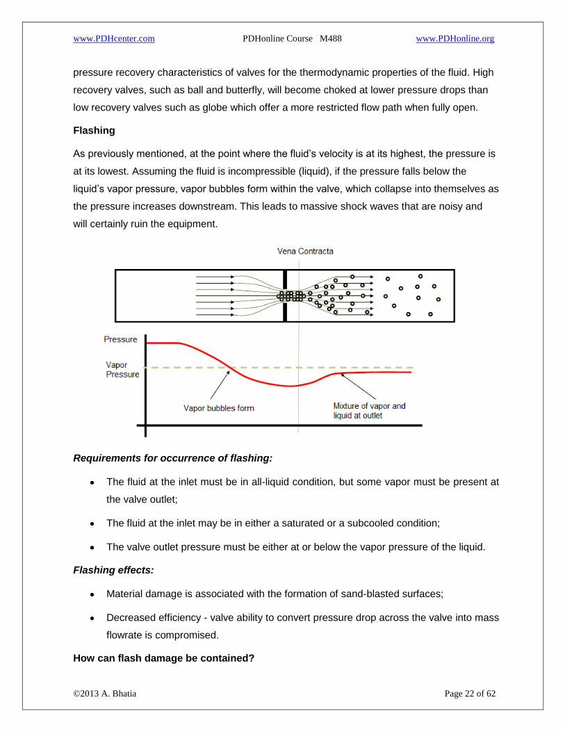
Flashing
As previously mentioned, at the point where the fluid’s velocity is at its highest, the pressure is
at its lowest. Assuming the fluid is incompressible (liquid), if the pressure falls below the
liquid’s vapor pressure, vapor bubbles form within the valve, which collapse into themselves as
the pressure increases downstream. This leads to massive shock waves that are noisy and
will certainly ruin the equipment.
Requirements for occurrence of flashing:
The fluid at the inlet must be in all-liquid condition, but some vapor must be present at
the valve outlet;
The fluid at the inlet may be in either a saturated or a subcooled condition;
The valve outlet pressure must be either at or below the vapor pressure of the liquid.
Flashing effects:
Material damage is associated with the formation of sand-blasted surfaces;
Decreased efficiency - valve ability to convert pressure drop across the valve into mass
flowrate is compromised.
How can flash damage be contained?

www.PDHcenter.com PDHonline Course M488 www.PDHonline.org
©2013 A. Bhatia Page 23 of 62
Under such scenario, there are two phases flowing downstream of the valve - liquid and
vapour. Flashing cannot be eliminated in the valve – if the downstream pressure is less than
the vapour pressure of liquid. However, the damage can be minimized by:
Hard face trim (using hard facing materials such as Stellite, or Tungsten Carbide),
more erosion resistant body material.
Increasing size of the valve, therefore reducing the velocity
Using angle valve – flow over plug
Cavitation
Cavitation is similar to flashing in a way that the liquid pressure drops to value below its vapour
pressure, causing a liquid to vaporize into vapor bubbles. Both cavitation and flashing occurs
because the pressure energy in a fluid is converted to kinetic energy due to the contraction at
the valve closure member, causing an increase in velocity. In addition, as the temperature of
the liquid increases, the likelihood of cavitation becomes more likely because of the increased
vapor pressure. The extent of the cavitation depends mainly on the downstream pressure and
the differential pressure across the valve.
The difference is that with the cavitation phenomenon, the liquid pressure increases over its
vapor pressure during pressure recovery and turns back into liquid state while during flashing
the liquid pressure remains below the vapour pressure throughout. The key differences are:
Requirements for occurrence of Requirements for occurrence of flashing:

www.PDHcenter.com PDHonline Course M488 www.PDHonline.org
©2013 A. Bhatia Page 24 of 62
cavitation:
The fluid at both the inlet and outlet must be
in all-liquid condition.
The fluid at the inlet must be in all-liquid
condition, but some vapor must be present at
the valve outlet.
The liquid must be sub-cooled state at the
inlet, because if the liquid will be in a
saturated state, then any pressure drop
across the valve will cause the presence of
vapor downstream.
The fluid at the inlet may be in either a
saturated or a sub-cooled condition.
The valve outlet pressure must be either at or
above the vapor pressure of the liquid.
The valve outlet pressure must be either at or
below the vapor pressure of the liquid.
How to avoid Cavitation?
If cavitation is ever encountered, consider the following corrective actions:
1. The first is to equip control valve with special trim and ensure that the plug and seat
are made of a hard facing material that can resist both the onset and effect of
cavitation (e.g. stellite hard facing).
2. The second is to use a valve with a low recovery coefficient (refer below).
3. The third is to increase the downstream pressure by installing a flow restrictor if
possible or reducing the pipe size of a short piece downstream.
Valve Recovery Coefficient
Valve recovery refers to the pressure recovery from the low pressure at vena contracta to the
valve outlet. The term "valve recovery" is usually applied when a valve is employed as a
restriction. It is a given that any valve could cause cavitation to a differing degree and in
different closure positions. If using a valve to cause a pressure drop as compared to control
the flow of volumes, it is safe to say that a low recovery valve will resist causing cavitation
more than a high recovery type.
The valve recovery coefficient is a dimensionless, numerical factor that represents a valve's
flow vs. liquid pressure curve, and thus the valve's tendency to cavitate. If this factor is higher

www.PDHcenter.com PDHonline Course M488 www.PDHonline.org
©2013 A. Bhatia Page 25 of 62
than desired, cavitation might develop. The valve coefficient is affected by the internal
geometry of the valve, valve size, pressure, and the presence or absence of piping reducers
adjacent to the valve.
CONTROL VALVE CHARACTERISTICS
Each valve has a flow characteristic, which describes the relationship between the flow rate
and valve travel. As a valve opens, the flow characteristic - which is inherent to the design of
the selected valve - allows a certain amount of flow through the valve at a particular
percentage of the stroke. This enables flow regulation through the valve in a predictable
manner. The three most common types of flow characteristics are:
1. Linear
2. Equal percentage
3. Quick opening
Linear valve characteristics
This characteristic provides a linear relationship between the valve position and the flowrate.
The flow through a linear valve varies directly with the position of the valve stem. This flow-
travel relationship, if plotted on rectilinear coordinates, approximates a straight line, giving
equal volume changes for equal lift changes, regardless of percent of valve opening.
These valves are often used for liquid level control and certain flow control operations
requiring constant gain.
Equal percentage valve characteristics
The equal percentage valve plug produces the same percentage change in flow per fixed
increment of valve stroke at any location on its characteristic curve. For example, if 30% stem
lift produces 5 gpm and a lift increase of 10% to 40% produces 8 gpm or a 60% increase over
the previous 5 gpm then a further stroke of 10% now produces a 60% increase over the
previous 8 gpm for a total flow of 12.8 gpm.
Comparison of Equal Percentage Change between Lift and Flow
Lift (%open) Change % Flowrate Change %
30% 5 GPM

www.PDHcenter.com PDHonline Course M488 www.PDHonline.org
©2013 A. Bhatia Page 26 of 62
10% 60%
40% 8 GPM
10% 60%
50% 12.8 GPM
These types of valves are commonly used for pressure control applications and are most
suitable for applications where a high variation in pressure drop is expected.
Quick opening valve characteristics
A quick opening valve plug produces a large increase in flow for a small initial change in stem
travel. Near maximum flow is reached at a relatively low percentage of maximum stem lift.
Quick opening plugs are normally utilized in two position “On-Off” applications but may be
used in some linear valve applications. This is possible because of its initial linear
characteristic at a low percentage of stem travel. The slope of this linear region is very steep
which produces a higher initial gain than the linear plug but also increases the potential
instability of the control valve.

www.PDHcenter.com PDHonline Course M488 www.PDHonline.org
©2013 A. Bhatia Page 27 of 62
Commonly observed inherent flow characteristic types
Inherent valve characteristics
An inherent flow characteristic is the relation between valve opening and flow under constant
pressure conditions. The inherent characteristic of a valve is obtained when there is a constant
pressure drop across the valve for all valve positions, the process fluid is not flashing,
cavitating or approaching sonic velocity (choked flow), and the actuator is linear (valve stem
travel is proportional to the controller output).
Some valves have inherent characteristics that cannot be changed - such as full port ball
valves and butterfly valves. For other valve types, such as globe, the inherent characteristics
can be changed to suit the application.
Difference between installed and inherent characteristics
The inherent flow characteristics do not reflect the actual performance of the valve as installed.
The ideal condition of constant valve pressure drop (ΔP) is unlikely to be true and the

www.PDHcenter.com PDHonline Course M488 www.PDHonline.org
©2013 A. Bhatia Page 28 of 62
‘operating’ characteristics will have deviation from the inherent characteristics and is termed
the “Installed Flow Characteristics”.
The deviation in the characteristics depends on the pressure drop variation across the control
valve, as the control valve operates from minimum flow at its initial travel position to its
maximum flow at its fully opened position. The variations in pressure drop across the valve
can be attributed to two basic causes.
1. The pump characteristic, which results in an increase in pump head as the flow is
reduced and,
2. The reduction in line losses as the flow is reduced, causing more and more of the
pump head to appear across the valve.
In a pipeline carrying fluid, the dynamic system pressure (Ps) is made up of two components,
1) the pressure drop across the control valve (Pv) and 2) the pressure drop along the pipeline
(PL), EXCLUDING any fixed static or elevation pressure head component. It is given by:
PS = Pv + PL
In the pump curve above, the point “A” is the point where the system resistance curve crosses
the pump characteristic curve and indicates the operating conditions (flow and head). As the
valve modulates to the closed position; the resistance to the system flow that the valve

www.PDHcenter.com PDHonline Course M488 www.PDHonline.org
©2013 A. Bhatia Page 29 of 62
provides (valve pressure drop) will increase by shifting from point “A” towards point “B”. This
increasing resistance will use more of the head in the system, as well as decrease system
flow.
Pressure drop across the control valve increases (ΔPv - ↑). The change in pressure
drop across the valve can be attributed to two basic causes: 1) the pump characteristic,
which results in an increase in pump head as the flow is reduced and 2) the reduction
in line losses as the flow is reduced, causing more and more of the pump head to
appear across the valve. The amount that the pump head will increase with a decrease
in system flow will depend upon the operating characteristics of the pump. A pump with
a steep characteristic will produce a considerable increase in pressure head as the
system resistance is increased. However, a flat characteristic pump will produce a
relatively constant, high pressure head for any system flow. The relatively constant
pressure would be preferable from a control standpoint.
Pressure loss in the pipeline reduces (ΔPL - ↓). This is because the decrease in
system flow will result in a decrease in pressure drop across along the pipeline and is
is proportional to the square root of the flow rate.
This indicates that the pressure drop across the valve in the system is not constant and it
varies with flow and other changes in the system. This has a significant impact on the actual
installed valve flow characteristic. The deviation from the inherent flow characteristic is a
function of a property called Valve Authority. It is defined as the ratio of the full flow valve
pressure drop to the system pressure drop (including the valve)
Where:
N = Valve Authority
ΔPv = Pressure drop across the control valve
ΔPL = Pressure drop due to pipeline friction losses
ΔPS = System pressure drop = ΔPv + ΔPL
When “N” approaches 1.0, then ΔPL is almost zero and ΔPv approaches ΔPs. This satisfies
the requirement for the definition of valve inherent characteristics.

www.PDHcenter.com PDHonline Course M488 www.PDHonline.org
©2013 A. Bhatia Page 30 of 62
Distortion occurs when “N” falls from 1.0. This is the situation when the pipeline system
pressure drop (ΔPs) is not concentrated at the control valve alone but well distributed along
the pipeline. An inherently equal % characteristics control valve operating under such
condition will behave like a linear valve and an inherently linear characteristics control valve
will behave like a quick-opening control valve.
The effect of these system variables can be minimized by keeping the relative change in valve
pressure drop as small as possible.
When the total flow is low, control valve pressure drop tends to be large fraction of the total
system pressure loss; but at high flows this may not be true. A good design will respond well
over the full range of conditions, hence it is important to pick the right characteristic for your
system and size the valve for the right amount of pressure drop. For good control, it is nice to
take a fairly large pressure drop across a control valve. This way it will have a big influence on
the total system, making the operators and control engineers happy. However, design
engineers will worry that increasing pressure drop will tend to increase pumping and other
operating costs. Compromise is necessary. As a rule of thumb, design the system and size the
valve so that 25 to 33% (1/3rd) of the total system pressures drop (including the valve) is taken
across the control valve, with a minimum of 10-15 psig.
At this point, let’s define two additional terms: 1) Rangeability and 2) Turndown and
define their relationship w.r.t valve authority.
Valve Rangeability - Rangeability indicates the extent of flow values that the valve can
reliably regulate and is often reported as a ratio of the largest to the smallest flows that can be
controlled acceptably.
A control valve with higher rangeability will control flow over wider flow rates. For example, a
valve with a rangeability of 50 and having a total flow capacity of 100 GPM; fully open, will
control flow accurately down as low as 2 GPM. Rangeability is affected by three factors:
1. Valve geometry – inherent rangeability due to the design of the body and the regulating
element.
2. Seat leakage – excessive seat leakage can cause instability as the valve lifts off of the
seat.
www.PDHcenter.com PDHonline Course M488 www.PDHonline.org
©2013 A. Bhatia Page 31 of 62
3. Actuator – diaphragm actuators are seldom accurate at less than 5% of the valve
opening, whereas piston-cylinder actuators can provide control within 1% of valve lift
due to the presence of air in two chambers.
Valves with high rangeability are sometimes desirable but these will be expensive to
manufacture since very close tolerances are involved between the disc and the seat. A typical
commercial valve generally has a rangeability of about 35 to 50.
Turndown - The ratio between maximum usable flow and the minimum controllable flow;
usually less than the rangeability. For instance, as stated above, after the 100 GPM valve has
been applied at a job, it might turn out that the most flow you would ever need through the
valve is 68 GPM. Since the minimum controllable flow is 2 GPM, the turndown for this valve is
34 to 1. In comparing rangeability and turndown, we may say that rangeability is a measure of
the predicted stability of the control valve, and turndown is a measure of the actual stability of
the valve.
Note:
The term rangeability applies to the valve whereas the term turndown applies to the
application. The rangeability of the selected valve must exceed the turndown
requirements of the application.
Mathematically we can define rangeablity as:
R = (Qmax / Qmin) x β½
Where:
R = valve rangeability
Qmax = design flow rate
Qmin = controllable flow rate
β = installed valve authority
The minimum controllable flow rate through a valve is a function of the valve design. It is
directly affected by all sources of friction within the valve assembly. In an ideal valve, any
change in signal applied to the actuator, even an infinitely small change, will force the valve
stem to move, even if that movement is infinitely small. However, friction represents a force
that must be overcome by the actuator. When the actuator exerts sufficient force to overcome

www.PDHcenter.com PDHonline Course M488 www.PDHonline.org
©2013 A. Bhatia Page 32 of 62
friction, the valve stem will move some finite amount. When this occurs when the valve is full
closed, this finite movement results in a certain minimum flow rate.
Example:
A valve has an installed authority of 35%. The design flow rate is 350 gpm. For good low-flow
control, we wish a minimum flow rate of not more than 2 gpm. We can calculate the required
rangeability as:
R = (350 / 2) x 0.35½ = 123
This means the valve must have a manufacturer's rangeability rating of 123:1 or greater. A
typical commercial valve generally has a rangeability of about 50:1. Industrial valves can have
a rangeability as high as 200:1. This is part of the reason why industrial valves are so much
more costly than a commercial valve.
Summarizing….
The installed characteristic of control valve matches with the inherent characteristic of control
valve:
When the friction losses in the pipeline are negligible and the major drop is due to
control valve.
When the valve authority approaches 1.
When the valve pressure drop at the maximum flow rate is nearly 1/3rd of the overall
system pressure drop (valve + line).
General rules:
How do you decide which valve control to use?
Here are some rules of thumb:
Linear Characteristics
Used in liquid level or flow loops.
Used in systems where the pressure drop across the valve is expected to remain fairly
constant (i.e. steady state systems).
Used when the pressure drop across the valve is a large proportion of the total
pressure drop.

www.PDHcenter.com PDHonline Course M488 www.PDHonline.org
©2013 A. Bhatia Page 33 of 62
Equal Percentage Characteristics
Used in processes where large changes in pressure drop are expected.
Used in processes where a small percentage of the total pressure drop is permitted by
the valve.
Used in temperature and pressure control loops.
Quick Opening Characteristics
Used for frequent on-off service.
Used for processes where "instantly" large flow is needed (i.e. safety systems or
cooling water systems).
Two rules of thumb for choosing the right flow characteristic:
1. If most of the pressure drop is taken through the valve and the upstream pressure is
constant, a linear characteristic will provide better control.
2. If the piping and downstream equipment cause significant resistance to the system,
equal percentage will provide better control.
************

www.PDHcenter.com PDHonline Course M488 www.PDHonline.org
©2013 A. Bhatia Page 34 of 62
SECTION - 3: CONTROL VALVE SIZING PARAMETERS
The valve is very important component of any process system. It is important not to choose a
valve that is too small or too large.
If the control valve is undersized (Cv - too small), the required flow rate will not be
achieved even when the valve is fully opened. If a higher pressure is applied to force a
higher flow rate across the undersized valve; not only the pump energy will be
excessive but also the valve may cavitate or develop flashing.
If a selected control valve is too large (Cv – too large), it will not provide the desired
control and may cause the system to hunt or cycle. When a valve is operated at below
10% of its Cv ono extended period of time, the valve seat and the closure member may
get damaged.
Control Valve sizing and selection is based on a combination of theory and empirical data.
Typical parameters used to select a valve are:
Flow medium
Service requirements (flow regulation or on-off type)
Pressure-Temperature rating
Material of construction
Valve Action (Normally Open vs. Normally Closed)
Valve size or valve coefficient (Cv)
Precision control
Leakage or Tight shut-off
Flow medium
Identifying the fluid that will flow through the valve is the first and most important consideration.
Highly erosive fluids, such as those carrying suspended solids or slurries, may require
full port valves which do not provide any obstruction to flow in the full open position.
Never specify butterfly valves for such services.

www.PDHcenter.com PDHonline Course M488 www.PDHonline.org
©2013 A. Bhatia Page 35 of 62
If the flow stream contains fibrous particles, it may block or plug the valve openings.
Diamond port plug valves, V-plug and V-ball valves have port shapes that minimize
plugging.
Highly viscous or gummy fluids create a high pressure drop through valves and piping.
Ball valves, diaphragm valves and butterfly valves are ideal for these services.
Service requirements
Ask the following questions:
Should the valve merely start and stop the flow?
Should it regulate (throttle) flow within a preset flow range limit?
Should it provide a combination of two functions above?
How much through valve leakage can the system tolerate?
Gate valves will provide tight shutoff but should not be used to regulate flow. Many
inexpensive control valves will provide throttling but may not provide shut tight, e.g., butterfly
valves can provide excellent flow control, but may not be bubble tight. It is often not possible to
achieve operational needs with a single, standard, off-the-shelf valve. A custom-built valve - or
two standard valves in series may often be required to obtain the desired results.
Pressure – Temperature Rating (P-T Rating)
Ask the following questions:
What is the maximum pressure that the valve needs to be rated for?
What are the upstream and downstream pressures for each of the maximum, normal
and minimum flow rates?
Is the valve operating consistently near the system's maximum design pressure and
temperature?
Do the system's peak pressure and temperature occur simultaneously? Do these
conditions peak out only when the valve is open?
These questions would decide the type of valve and its seating material. Here, we need to
make distinction between “line pressure v/s valve pressure drop”.
Often this is a misunderstood. The valve pressure envelope (valve body) is subjected to the
full line pressure (valve upstream pressure), whereas the pressure drop (ΔP) is the difference

www.PDHcenter.com PDHonline Course M488 www.PDHonline.org
©2013 A. Bhatia Page 36 of 62
between the valve upstream pressure and the pressure that exists just downstream of the
valve. Both pressures are equally important when selecting a control valve. The line pressure
determines the valve body (and pipe flange) rating, whereas the pressure drop determines the
valve trim or seat rating.
The pressure-temperature rating of a valve is simply the maximum pressure the valve is
designed to handle at a particular temperature and varies with the material of construction.
The higher the process temperature, the less pressure can be handled by the body sub-
assembly.
Valve’s pressure rating describes the range of pressures a valve can handle - the higher the
rating, the thicker the walls of the valve vessel to prevent rupture. The standard ANSI ratings
are: 150, 300, 600, 900 etc. ANSI 150 rating valve does not mean that the maximum pressure
rating of this valve is only 150 psi; a steel valve that is rated as ANSI class 150 can handle
pressures up to 285 psi at 100°F (refer the chart below).

www.PDHcenter.com PDHonline Course M488 www.PDHonline.org
©2013 A. Bhatia Page 37 of 62
Source: ANSI B16.34
Materials of construction
General Service valves are specified with commonly found materials to match the pipe
material. The standard materials are:
Carbon Steel
Stainless Steel
Chrome-moly
For special services, the construction is often guided primarily by the type of fluid, service
temperature etc. Here are few examples:
Concentration of the material in the fluid is very important. Most chemicals are easier to
handle in dilute concentrations. However, acids—such as sulfuric acid—become more
aggressive as they are diluted with water. Some organic materials that are not
corrosive by themselves become so in the presence of water.
Temperature is an important factor in choice of materials because high temperature
increases corrosion. In addition, at very elevated temperatures, the pressure rating of
the valve can be severely lowered due to deterioration of either metallic or non-metallic
material properties.
Materials used in valves in hydrocarbon service experience sulfide stress cracking.
NACE standard MR-01-75 provides specific guidelines for their selection criteria.
Cast carbon steel (ASTM A216 – Grade WCB) is the most popular steel for valve
bodies in moderate service such as air, superheat or saturated steam, non-corrosive
fluids.
Cast chrome-moly steel (ASTM A217 – Grade WCB-C9) has addition of
chromium/Molybdenum that provide corrosion resistance and also suitable for
temperature up to 1050ºF.
Cast type 304 SST (ASTM A351 – Grade CF8) is for oxidizing and very corrosive
fluids.
Cast type 316 SST (ASTM A351 – Grade CF8M) is same as 304 SST but since it has
addition of Molybdenum it has better resistance to corrosion.

www.PDHcenter.com PDHonline Course M488 www.PDHonline.org
©2013 A. Bhatia Page 38 of 62
Cast Iron (ASTM A126) is used for steam, water, gas and non-corrosive fluids and is
inexpensive.
Cast Bronze (ASTM B61 and B62) is used for steam, air, water, oil and non-corrosive
fluids.
Also ask this question: Does the valve stay closed (or open) most of the time? Many materials
exhibit different corrosion characteristics in stagnant versus flowing conditions. A case in point
is Monel - a nickel-copper alloy. Monel is extremely well-suited to handling brine in flowing
conditions, but is a poor choice in stagnant conditions (Inconel would be a better choice).
Valve Action
Valve action defines whether the valve will be fully open, or fully closed in event of any
process failure. The engineer must define whether the safest condition for each valve is fully
open or fully closed. This will be the failure position, and the combination of the actuator and
valve body must achieve this position upon loss of power. We must analyze the entire
process, including integrated units to identify the safest conditions. In a few cases, the failure
condition is “unchanged”. If the air power is lost, air leakage will result in a slow drift to either
open or closed.
Let’s take an example:
If the valve is used to control steam or fuel flow, the valve should be shut off completely. On
the other hand, if the valve is handling cooling water to a reactor, the flow should be maximum
in case of emergency. Control valves operated through pneumatic actuators can be either (i)
air to open, or (ii) air to close. If all the power goes out or some other emergency occurs, the
decision on the fail-safe mode of the valve is a huge factor in saving lives.
Valve Size (Capacity)
Valves are sized according to their Cv value. For liquid service, the equation for Cv is:
The required flow and pressure drop information used to size a valve is based on the process
operations and equipment. Once the Cv value is known, the rated* Cv can be determined from
the manufacturer's data books. A general guideline is that valves should be sized so that
maximum flow is obtained at about 90% valve open. Valves should be able to provide normal
flow condition at around 60% - 70% of the travel. Valve should provide minimum flow when

www.PDHcenter.com PDHonline Course M488 www.PDHonline.org
©2013 A. Bhatia Page 39 of 62
about 10% open. The control valve need not be of the same size as the pipe. It is better to
make an error in under sizing a control valve than to oversize it.
As a good engineering practice, the rated Cv of the valve shall be in accordance with following
criteria:
If normal flow is specified:
Calculated Cv – Based on the normal flow
Selected Cv – Based on 1.4 x normal flow
If maximum flow is specified but is equal to or less than 1.4 x normal flow
Calculated Cv – based on normal flow
Selected Cv – based on 1.5 x normal flow
When maximum flow is specified but is greater than 1.4 x normal flow
Calculated Cv – Bsed on normal flow
Selected Cv – Based on 1.1 x maximum flow
Precise system control
Some system control loops require highly accurate control in the face of severe disturbances.
Ideally the control valve should have low friction, no backlash, and a stable flow pattern.
Rotary valves, such as high-performance butterfly and plug valves employing low-
friction bearings and packings provide good control.
Ball valves have large backlash and are not recommended.
Linear motion valves, such as globe valves cannot match the low friction of rotary
valves and must be critically evaluated.
Leakage or Tight shut-off
A valve having tight shutoff will have virtually no flow or leakage in its closed position.
Generally speaking, only single-seated valves have tight shutoff. Double-seated valves may
be expected to have a leakage of 2 – 5% while in closed position. Control valve seat leakage
shall be designed and constructed in accordance with the requirements to ANSI B 16-104.
Class I – N/A
Class II - 0.5% of maximum valve capacity

www.PDHcenter.com PDHonline Course M488 www.PDHonline.org
©2013 A. Bhatia Page 40 of 62
Class III - 0.1% of maximum valve capacity
Class IV - 0.01% of maximum valve capacity
Class V – 0.0005 ml/min/inch of port dia./psi differential
Close-off pressure is an important parameter that defines the differential pressure required to
seat the valve and stop flow completely and is a function of the hydraulic design of the system
and the criteria for deciding the type of valve actuator. Typically, actuators are either electronic
or pneumatic. The significant performance differentiator between the two is speed of
operation. While the electric actuators are better known for their high levels of precision; the
pneumatic actuators very popular due to their relatively low cost, high power output, and
reliability. The choice of pneumatic or electric actuators involves an evaluation of performance,
component costs, system costs, and productivity gains. Each has inherent advantages and
disadvantages. Refer section-1 for detailed comparison.
Note- Automatic control valves are not designed to produce “tight shutoff” and will likely to be
prone to small amount of leakage when closed. Consequently, most control valve installations
include block valves, manual valves which can be turned when complete shutoff is needed.
CONTROL VALVE SIZING EQUATIONS
In order to determine the correct size of a valve for a specific system many factors must be
considered. The most important factor is the capacity parameter, Cv, or the flow coefficient.
To determine the valve size needed for your system, you can estimate Cv with the following
equations:
Liquids (water, oil, etc.)
Because liquids are incompressible fluids, their flow rate depends only on the difference
between the inlet and outlet pressures (ΔP, pressure drop). The flow is the same whether the
system pressure is low or high, so long as the difference between the inlet and outlet pressure
is the same. The equation below shows the relationship:
Where,
Cv = Valve flow coefficient, US GPM with P = 1 psi
Q = Fluid flow, US GPM

www.PDHcenter.com PDHonline Course M488 www.PDHonline.org
©2013 A. Bhatia Page 41 of 62
S = Specific gravity of fluid relative to water @ 60F
ΔP = Pressure drop (P1 – P2) at maximum flow, psi
Specific gravity correction is negligible for water below 200F (use S = 1.0). Use actual specific
gravity S of other liquids at actual flow temperature. Use the following equation for fluids with
viscosity correction factor. Use actual specific gravity S for fluids at actual flow temperature.
Where,
K = Viscosity correction factor for fluids
Estimating diameter of pipe:
Another important piece of information about sizing and specifications is what diameter pipe
may be used with a certain flow, seen in the following equation:
Where:
d = diameter of pipe (ft.)
Q max = maximum flow through the valve (ft3 / s)
v = velocity of flow (ft./s)
Air and Gaseous Flow (natural gas, propane etc.)
Gas flow calculations are slightly more complex because gases are compressible fluids whose
density changes with pressure. In addition, there are two conditions that must be considered –
low pressure drop flow and high pressure drop flow.
Use following equation when outlet pressure (P2) is greater than one half of inlet pressure (P1).
Use following equation when outlet pressure (P2) is less than or equal to ½ of inlet pressure
(P1).

www.PDHcenter.com PDHonline Course M488 www.PDHonline.org
©2013 A. Bhatia Page 42 of 62
Where,
Cv = Valve flow coefficient, US GPM with P = 1 psi
Qa = Air or gas flow, standard cubic feet per hour (SCFH) at 14.7 psig and 60F
T = Flowing air or gas temperature (F)
ΔP = Pressure drop (P1 – P2) at maximum flow, psi
P2 = Outlet pressure at maximum flow, psia (abs.)
P1 = Inlet pressure at maximum flow, psia (abs.)
The relationship between the inlet and outlet pressure is important, as seen above, in
determining which equation to use for gaseous flow. When the outlet pressure is less than ½
the inlet pressure, this is said to be a critical pressure drop. The gas will behave differently
when the pressure drop is critical; therefore it is necessary to use the correct equation
depending on the extent of pressure drop. Once you have computed the desired value of Cv,
you can choose the valve. The chosen valve must have a valve coefficient greater than or
equal to the computed value.
For Steam (saturated or superheated)
Use following equation when P2 is greater than ½ P1
Use following equation when P2 is less than or equal to ½ P1
Where,
Cv = Valve flow coefficient, US GPM with P = 1 psi
W = Steam flow, pound per hour (lb. /hr.)
K = 1 + (0.0007 x F superheat) for steam

www.PDHcenter.com PDHonline Course M488 www.PDHonline.org
©2013 A. Bhatia Page 43 of 62
T = Flowing air or gas temperature (F)
ΔP = Pressure drop (P1 – P2) at maximum flow, psi
P1 = Inlet pressure at maximum flow, psia (abs.)
P2 = Outlet pressure at maximum flow, psia (abs.)
CONTROL VALVE SIZING – SIMPLIFIED EXAMPLE
Define the system
Water is pumped from one tank to another through a piping system with a total pressure drop
of 150 psi. A control valve is provided in the piping loop to modulate the flow rates. Assume
the following key variables:
Fluid temperature - 70ºF
Design (maximum) flow rate - 150 gpm
Operating flow rate - 110 gpm
Minimum flow rate - 25 gpm
Pipe diameter - 3 inches
Specific gravity – 1.0
Valve characteristic – Globe valve, equal percentage
STEP #1:
Define a maximum allowable pressure drop for the valve
When defining the allowable pressure drop across the valve, you should first investigate the
pump. What is its maximum available head? Remember that the system pressure drop is
limited by the pump. Essentially the Net Positive Suction Head Available (NPSHA) minus the
Net Positive Suction Head Required (NPSHR) is the maximum available pressure drop for the
valve to use and this must not be exceeded or another pump will be needed. It's important to
remember the trade off, larger pressure drops increase the pumping cost (operating) and
smaller pressure drops increase the valve cost because a larger valve is required (capital
cost).
The usual rule of thumb is that a valve should be designed to use 10-15% of the total pressure
drop or 10 psi, whichever is greater. For our example, 10% of the total pressure drop is 15 psi

www.PDHcenter.com PDHonline Course M488 www.PDHonline.org
©2013 A. Bhatia Page 44 of 62
which is what we'll use as our allowable pressure drop when the valve is wide open (the pump
is our system is easily capable of the additional pressure drop.
STEP # 2:
Calculate the valve coefficient (Cv)
The next step is to figure out what size the valve will need to be. Key elements to consider in
valve sizing are the pressure-flowrate relationship and the flow characteristics to ensure an
appropriate size for the desired valve.
For our system,
Cv = 150 (1/15)½ = 38.7 = 39
STEP # 3:
Preliminary valve selection
The Cv value should be used as a guide in the valve selection, but before trying to match a
valve with the calculated Cv value, some other considerations are:
Decide what type of valve will be used for given process characteristic;
Never use a valve that is less than half the pipe size;
Avoid using the lower 10% and upper 20% of the valve stroke. The valve is much
easier to control in the 10-80% stroke range.
In our example we are using an equal percentage, globe valve. Obtain the valve chart for this
type from the manufacturer – typical shown below:

www.PDHcenter.com PDHonline Course M488 www.PDHonline.org
©2013 A. Bhatia Page 45 of 62
For our case, it appears the 2½ inch valve will work well for our Cv value at about 80-85% of
the stroke range. Notice that we're not trying to squeeze our Cv into the 2” valve which would
need to be at 100% stroke to handle our maximum flow. If this valve were used, two
consequences would be experienced: the pressure drop would be a little higher than 15 psi at
our design (max) flow and the valve would be difficult to control at maximum flow. Also, there
would be no room for error with this valve, but the valve we've chosen will allow for flow surges
beyond the 150 gpm range with severe headaches!
So it looks a 2½” valve will suffice the duty….but before we make a decision, there are still
some characteristics to consider. Go to step # 4.
STEP # 4:
Check the Cv and stroke percentage at the minimum flow
If the stroke percentage falls below 10% at our minimum flow, a smaller valve may have to be
used in some cases. Judgments plays role in many cases.
For example, is your system more likely to operate closer to the maximum flowrates more
often than the minimum flowrates? Or is it more likely to operate near the minimum flowrate for
extended periods of time. It's difficult to find the perfect valve, but you should find one that
operates well most of the time. Let's check the valve we've selected for our system:
Cv = 25 (1 / 15)½ = 6.5

www.PDHcenter.com PDHonline Course M488 www.PDHonline.org
©2013 A. Bhatia Page 46 of 62
Referring back to our valve chart, we see that a Cv of 6.5 would correspond to a stroke
percentage of around 30 - 35% which is certainly acceptable. Notice that we used the
maximum pressure drop of 15 psi once again in our calculation. Although the pressure drop
across the valve will be lower at smaller flowrates, using the maximum value gives us a "worst
case" scenario. If our Cv at the minimum flow would have been around 1.5, there would not
really be a problem because the valve has a Cv of 2.1 at 10% stroke and since we use the
maximum pressure drop, our estimate is conservative. Essentially, at lower pressure drops, Cv
would only increase which in this case would be advantageous.
STEP # 5: Check the gain across applicable flow rates
Gain is defined as:
Gain = Δ Flow / Δ Travel
Now, at our three flow rates:
Qmin = 25 GPM
Qop = 110 GPM
Qdes = 150 GPM
We have corresponding Cv values of 6.5, 28, and 39. The corresponding stroke percentages
are 30%, 68%, and 82% respectively. Now we construct the following table:
Flow (GPM) Stroke or Valve
Travel, VT (%)
Change in flow
(GPM)
Change in VT (%)
25 30 110 – 25 = 85 68 – 30 = 38
110 68 150 – 110 = 40 82 – 68 = 14
150 82
Gain #1 = 85/38 = 2.2
Gain #2 = 40/14 = 2.86
The difference between these values should be less than 50% of the higher value.
0.5 x (2.85) = 1.43 and 2.86 - 2.2 = 0.66.
www.PDHcenter.com PDHonline Course M488 www.PDHonline.org
©2013 A. Bhatia Page 47 of 62
Since 0.66 is less than 1.43 there should be no problem in controlling the valve. Also note that
the gain should never be less than 0.50.
So for our example, 2½” valve size will work fine.
OTHER NOTES:
Under most situations, sizing of a control valve for liquids can be based on valve Cv using a
simple flow equation. However, in many situations, other factors—such as compressible flows,
choked flow, viscous flows, pipe size, elbows, pipe reducers/expanders etc. – must be
determined. Formulae for these situations can be extremely complex, and the valve
manufacturers should be consulted. Refer to the manufacturer’s catalogs for more details:
http://www.pro-quip.com/images/proquip/PDFs/Library/ValtekSizingSelection/SS_03.pdf)
http://www.cheresources.com/content/articles/fluid-flow/valve-sizing-and-selection?pg=2
www.PDHcenter.com PDHonline Course M488 www.PDHonline.org
©2013 A. Bhatia Page 48 of 62
SECTION - 4: CONTROL VALVES IN PROCESS DRAWINGS
Engineers document their work using many complementary methods. A Piping and
Instrumentation Diagram - P&ID, is the most common method of illustrating the functional
relationship of piping, valves (automated and manual), pipe sizes, sample points and
instrumentation. A moderate level of mechanical detail is provided for process equipment, so
that the piping and instrumentation can be precisely documented. International symbol
standards are used for piping, equipment and instruments (ISA, 1992).
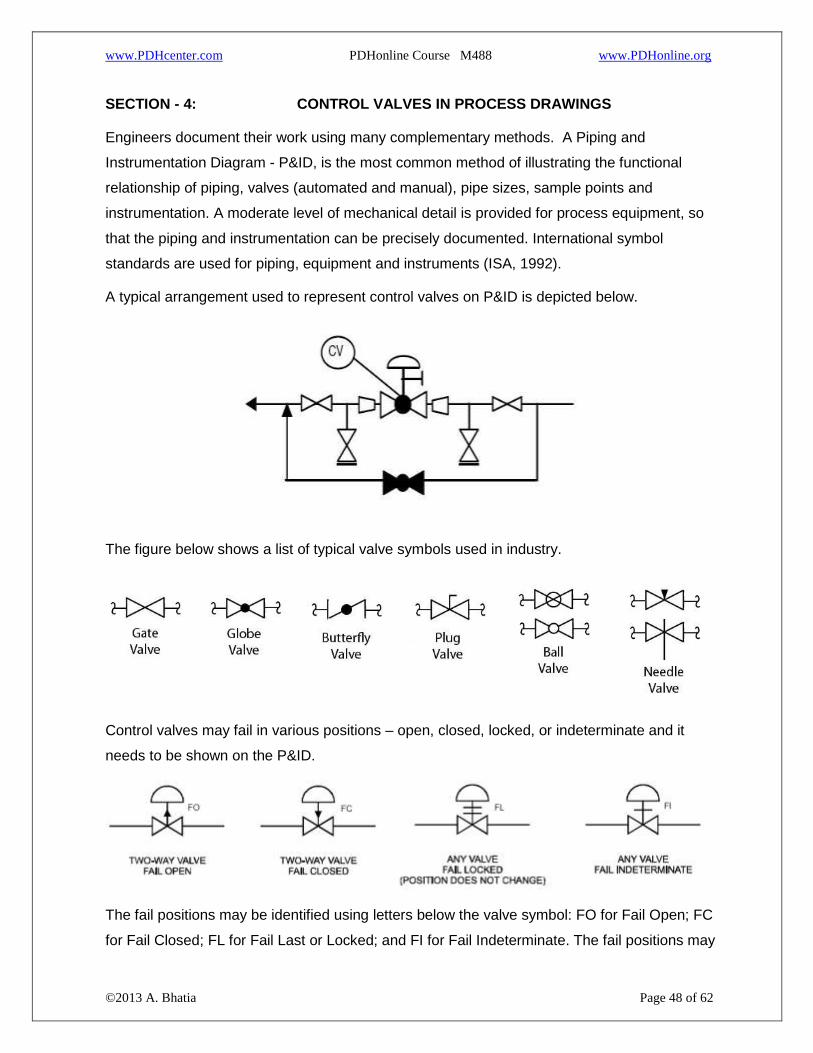
A typical arrangement used to represent control valves on P&ID is depicted below.
The figure below shows a list of typical valve symbols used in industry.
Control valves may fail in various positions – open, closed, locked, or indeterminate and it
needs to be shown on the P&ID.
The fail positions may be identified using letters below the valve symbol: FO for Fail Open; FC
for Fail Closed; FL for Fail Last or Locked; and FI for Fail Indeterminate. The fail positions may

www.PDHcenter.com PDHonline Course M488 www.PDHonline.org
©2013 A. Bhatia Page 49 of 62
also be identified by an arrow. An arrow up signifies the valve fails open and an arrow down is
fail close. A crossing line is fail indeterminate. Two crossing lines indicate fail locked or last
position.
Control Loop Representation on P&ID
Instrumentation and control design engineers add all the loop and local instruments to the
P&ID, to define the instrumentation and control scheme. Let’s take a problem statement of
controlling flow rate in the pipeline.
Figure below shows an electronic loop consisting of a flow control element (orifice plate), flow
transmitter, controller, transducer and a fail open control valve.
FT (Flow transmitter) senses the differential pressure proportional to the flow rate in the
line caused by a flow element or orifice plate and transmits a 4-20 mA dc (direct
current) signal corresponding to the varying differential pressure.
FIC (Electronic flow controller) transmits a 4-20 mA dc signal to the converter or
transducer, FY.
FY (Transducer) converts the 4-20 mA DC signal into a pneumatic signal. This signal
changes the position of the valve actuator, which in turn changes the position of the
control valve trim causing change in flow through the control valve.
The dotted line indicates that information is transmitted electronically from the flow transmitter,
FT, to the controller, FIC, and from the controller to pneumatic converter (I/P), FY. Simple
instruments permit direct reading of a process variable in the field. These devices include
pressure gauges, thermometers, level gauges and rotameters. Other loops are slightly more

www.PDHcenter.com PDHonline Course M488 www.PDHonline.org
©2013 A. Bhatia Page 50 of 62
complex, transmitting a signal to the remote control room, where the measurements can be
read or recorded.
Controllers
There are three basic types of controllers – 1) digital (e.g. microprocessor or computer based),
2) analog, and 3) pneumatic. The following guidelines may be applied in selecting the
appropriate controller:
For plants with many control loops use digital type of controllers.
For the expansion of existing controls within a plant use the existing technology. This
may be either digital, analog electronic, or pneumatic controllers.
Use pneumatic controllers in hazardous areas.
Avoid use of pneumatic controllers in the control room.
When using digital control avoid depending on a single or a few control devices for the
entire plant without having a backup. A redundant controller might not be required if
only a single controller controls one loop. However, if a single controller controls a
large number of loops then provide redundancy so that if the controller fails another
controller will automatically take over.
Use the type of controller that is the most economical and reliable.
Process Controllers
Process controllers use one or several of the following control modes:
1. On-off
2. Proportional
3. Integral (also called reset)
4. Derivative (also called rate)
Most digital controllers have all of the above control modes included. They are also usually
provided with anti-reset windup. Analog and pneumatic controllers often do not include all
three control modes or anti-reset windup.
Control modes

www.PDHcenter.com PDHonline Course M488 www.PDHonline.org
©2013 A. Bhatia Page 51 of 62
In general, use the following control modes for the indicated control loop.
Flow -- Use proportional plus integral.
Level -- Use proportional plus integral.
Pressure and Temperature -- Use proportional plus integral.
Note - Use proportional plus integral plus rate when the application requires a quick response
time
General Good Engineering Guidelines
1. The control valve size is generally smaller than the corresponding line size. This
change in diameter should be clearly indicated in the P&ID with reducer and expander.
2. Provide manual block and bypass valves around control valves where practical to allow
for control valve removal and servicing while the system is operational. If a manual
bypass is not provided then furnish the valve with a hand wheel.
3. A drain valve is normally always provided between the control valve and upstream
isolating valve. If the control valve is of ‘Fail Open’ type, this drain valve is sufficient to
drain the piping segment. If the control valve is of ‘Fail Close’ or ‘Fail in Position’ type,
then additional drain valve is required between the control valve and downstream
isolating valve.
4. Additional details such as failure position, tightness class, # rating etc. are also
indicated on the P&ID for control valves, as per the project standards.
5. End Connections
Threaded ends are cheap but can be stripped and leak; use these where this isn’t a
worry

www.PDHcenter.com PDHonline Course M488 www.PDHonline.org
©2013 A. Bhatia Page 52 of 62
Welded ends provide no leaks and are cheap initially, but if there are problems the
valve must be cut out.
Flanged ends are the most expensive but are the best from an installation and
removal standpoint.
6. Locate control valves at grade where practical. Install the control valve near the
operating equipment that has to be observed while in local manual control. Equipment
must be located so that they do not interfere with each other and so that space is
available for people to travel through the process and perform tasks, such as
maintenance.
COMMON QUESTIONS
1. What are the common control valve applications?
Control valves are used in following applications:
Pressure Reducing
Pressure Relief/Sustaining
Pump Control
Rate-of-Flow Control
Level Control
Cavitation Control
Surge Anticipation
Electronic Control
Metering
2. What is a pressure reducing valve?
Pressure reducing valve reduces a higher inlet pressure to a constant downstream pressure
regardless of demand and supply pressure fluctuations. It enables delivery of water at safe
pressures and adequate levels in various applications such as main feed, fire and irrigation
systems.
3. What is a pressure relief valve?
www.PDHcenter.com PDHonline Course M488 www.PDHonline.org
©2013 A. Bhatia Page 53 of 62
Pressure relief valve relieves excess pressure while maintaining a minimum upstream
pressure. It prevents downstream demand from sacrificing supply of an upstream zone. It is
typically installed in protection of in-line distribution piping at booster pump stations.
4. What is rate of flow control valve?
Rate of flow control valve maintains a maximum flow rate setting downstream regardless of
pressure changes. It is typically installed within distribution systems and process control
applications.
5. Can two control valves be used in series in high pressure drop applications?
Dropping the pressure across two valves rather than one is theoretically better. However, in
practice, the two valves will not usually control well together unless the process can operate
with a very low proportional band with slow response times.
A better and usually less expensive approach is to use a valve that is designed with multiple
pressure drop restrictions inside the trim.
6. Can two control valves be used in parallel to handle high turndown
applications?
Two valves in parallel working on split range signals can give very high turndown
capability. The situation that should be avoided if possible is that the larger valve
operates in the "cracked open" position – one way to avoid this is to program the PLC
or DCS to shut the small valve and use only the larger unit once the capacity of the
small valve is exceeded.
An alternative to two valves in parallel is to select a valve with a high rangeability such
as a V-port ball valve.
7. Is flow through a Control Valve – Turbulent or Laminar?
Flow through control valves is almost always turbulent.
Laminar flow takes place with liquids operating at low Reynolds numbers. This occurs with
liquids that are viscous, working at low velocities. Laminar flow in gases and vapours very
seldom will be experienced in process plants.
8. The control valve size is essentially always equal to the line size. Is this correct?
NO. The control valve need not be of the same size as the pipe.

www.PDHcenter.com PDHonline Course M488 www.PDHonline.org
©2013 A. Bhatia Page 54 of 62
Don’t assume a 4” valve will handle the flow in a 4” line. The flow path is the critical factor and
shape of the flow passage in the valve can be a problem. Look at the pressure through the
valve and if the valve creates a pressure drop than a slightly larger valve may be needed.
Always calculate the flow coefficient. Even for a given size of valve, there is no industry-wide
standard pressure for valve sizes; no two manufacturers design a 4" valve the same way, and
different designs have different pressure considerations. Contrary to conventional wisdom, it is
better to make an error in under sizing a control valve than to oversize it.
9. Is the velocity of a fluid in a control valve critical?
The velocity is one of the most important considerations in sizing a control valve. For long life
on liquid applications the velocity at the exit of the valve body should be less than 10 m/s. This
compares with generally accepted line velocities of about 3 m/s, which explains why control
valves often are smaller than the line size.
On gases and vapors the velocity at the exit of the valve body should be less than 0,33 Mach
(1/3rd of sonic) for noise control valves and less than 0,5 Mach where noise is not a
consideration.
10. What is a “modulating pressure independent” control valve?
A modulating pressure independent control valve does not allow a change in flow rate when
the pressure differential across the valve changes. Flow only changes with a change in valve
position.
11. What pressure and temperature requirements should be considered in selection
of control valves?
The selection of a control valve must be in accordance with established material properties.
ANSI Standard B16.34 lists the allowable temperature and pressure combinations for a variety
of body materials. Standard pressure classes include ANSI Classes 150, 300, 600, 900, 1500,
2500 and 4500. For a given body material, each class denotes the maximum working pressure
for a given operating temperature. Due to loss of material strength, the allowable working
pressure decreases as the operating temperature rises. Lower temperature limits are also
specified due to loss of ductility in some materials. Although a pressure class is usually
indicated for an application, proper attention to selection of the pressure class is crucial to the
safe operation of the control valve.
12. What's the difference between balanced and unbalanced valves?

www.PDHcenter.com PDHonline Course M488 www.PDHonline.org
©2013 A. Bhatia Page 55 of 62
Outlet balancing is required for proper valve functioning in those applications where the outlet
pressure is more than 25% of the inlet pressure. When the outlet pressure is relatively high
compared to the inlet pressure, the normally closed poppet will sometimes be pushed up off
the internal orifice by the back pressure on the valve. Outlet balancing prevents the
backpressure from acting on the poppet.
13. How do the characteristics of the actuator influence the control valve operation?
The valve and actuator are engineered to work together. Most manufacturers provide
an anti‐hunting algorithm in the valve that prevents the valve from modulating until it
exceeds the tolerance of the valve. Use spring-loaded diaphragm type actuators where
practical. Spring-less operators and cylinder operators are acceptable only when spring-
loaded diaphragm type actuators cannot provide the desired performance. Select the actuator
so that the valve or damper that it controls will fail safe. Fail safe is defined as lock in position
or take a position (either open or closed) that will result in the least upset.
14. What type of end connections specified for control valves?
Most control valve specifications request raised face flange connections suitable for bolting to
the process piping. In power piping and nuclear applications, butt weld ends suitable for
welding to the process piping are typical. For limited applications, screwed end connections
(NPT) and socket-weld ends are specified for globe valves in sizes 2-inch and smaller. Some
high pressure applications may require the use of RTJ (ring-type joint) flanges. Flangeless,
wafer-style connections are specified in applications where rotary valves are suitable for the
process conditions. These connections are usually raised face.
15. What are the common types of flow characteristics for control valves?
There are three basic types of control valve characteristics. These are quick opening, linear,
and equal percentage. A quick opening valve would flow approximately 70% of its full flow at
an valve opening of approximately 30%; a linear valve would flow approximately 50% of its full
flow at a valve opening of approximately 50%; and the equal percentage valve (logarithmic)
would flow 30% at approximately 70% of its full opening. So the question is - where would you
use one style of valve over another!
A quick-opening characteristic is recommended for shut off service only. Not much
use for modulating process control except in ON-OFF application.
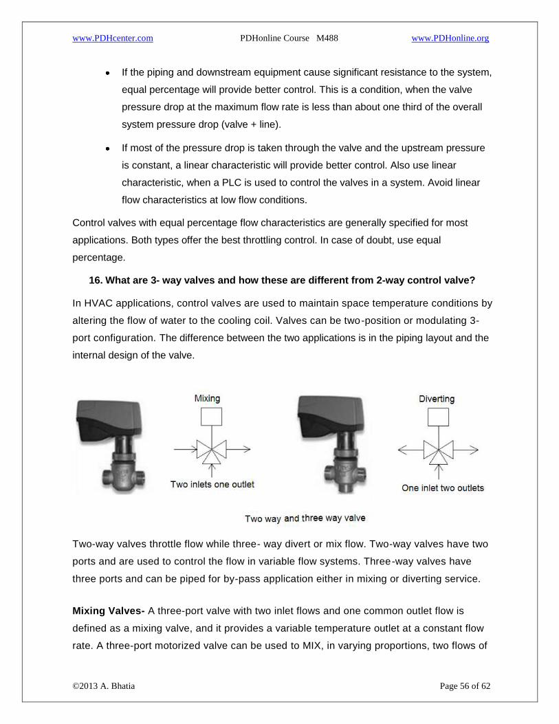
www.PDHcenter.com PDHonline Course M488 www.PDHonline.org
©2013 A. Bhatia Page 56 of 62
If the piping and downstream equipment cause significant resistance to the system,
equal percentage will provide better control. This is a condition, when the valve
pressure drop at the maximum flow rate is less than about one third of the overall
system pressure drop (valve + line).
If most of the pressure drop is taken through the valve and the upstream pressure
is constant, a linear characteristic will provide better control. Also use linear
characteristic, when a PLC is used to control the valves in a system. Avoid linear
flow characteristics at low flow conditions.
Control valves with equal percentage flow characteristics are generally specified for most
applications. Both types offer the best throttling control. In case of doubt, use equal
percentage.
16. What are 3- way valves and how these are different from 2-way control valve?
In HVAC applications, control valves are used to maintain space temperature conditions by
altering the flow of water to the cooling coil. Valves can be two-position or modulating 3-
port configuration. The difference between the two applications is in the piping layout and the
internal design of the valve.
Two-way valves throttle flow while three- way divert or mix flow. Two-way valves have two
ports and are used to control the flow in variable flow systems. Three-way valves have
three ports and can be piped for by-pass application either in mixing or diverting service.
Mixing Valves- A three-port valve with two inlet flows and one common outlet flow is
defined as a mixing valve, and it provides a variable temperature outlet at a constant flow
rate. A three-port motorized valve can be used to MIX, in varying proportions, two flows of

www.PDHcenter.com PDHonline Course M488 www.PDHonline.org
©2013 A. Bhatia Page 57 of 62
different temperatures while maintaining a constant rate of flow in the common outlet port.
Example: Mix hot and cold water (2 inlets) to make warm water (1 outlet). This is like a single
handle sink faucet where you move the lever to get the water temperature you want. A Mixing
Valve is used normally for radiator circuits.
Diverting Valves- A three-port valve may also be used to DIVERT a common flow in
varying proportions. The valve will have one inlet and two outlets and provides a constant
temperature and variable flow rate. Example: 100 GPM of flow (1 inlet) is divided into a 70
GPM stream and a 30 GPM stream (2 outlets). A diverting valve is used normally for circuits
with convective heat transfer such as; heat exchangers, primary coil in indirect cylinder,
heater battery, cooling coil.
2-way Valve or 3-way Valve
2-way valve is best when applied with variable speed pumps. Rather variable-pumping
systems should only use 2-way valve to reap the energy saving benefits.
The constant volume systems may employ 2-way or 3-way valve. While pumping costs will
decrease to small amount with 2-way valve, other problems occur. The 2-way valves with
constant volume system may some time lead to balancing problems in large network and
may lead to water scarcity at some terminal locations. The pumps must incorporate the
minimum recalculating system should the 2-way valve/s close to 100% close position. The
systems incorporating 3-way valve ensure continuous circulation.
The type of three-way valve selected will determine its location in the system.

www.PDHcenter.com PDHonline Course M488 www.PDHonline.org
©2013 A. Bhatia Page 58 of 62
2-way and 3-way Valve Circuits for HVAC Applications
Note - that the mixing valves are placed on the return side of the circuit and the diverting
valves are placed on the supply side.
17. What are the common issues associated with the control valves selection?
The major issues in valve selection are summarized below. The relative importance of each
issue depends upon the specific application; for example, one application might require a low
pressure drop, while another might require a large range. Generally, we find that the greater
the requirements for good performance, the higher the cost for purchase and maintenance.
Therefore, we must find the proper balance of performance and cost, rather than always
specify the best performing valve.
Precision
Ideally, the valve would move to exactly the position indicated by the signal to the valve, which
is usually a controller output. However, the valve is a real physical device that does not
perform ideally. The following factors prevent ideal performance.
Deadband - A valve with dead band acts like there is some backlash between the
controller output and the actual valve position. Every time the controller output
changes direction, the dead band has to be traversed before the valve physically

www.PDHcenter.com PDHonline Course M488 www.PDHonline.org
©2013 A. Bhatia Page 59 of 62
starts moving. Although dead band may be caused by mechanical backlash
(looseness or play in mechanical linkages); it can also be caused by excessive
friction in the valve, an undersized actuator, or a defective positioner. Many people
use the term Hysteresis instead of dead band but the ISA clearly calls the
mechanical backlash phenomenon in control valves as dead band.
Resolution - The smallest amount that the signal to the valve can be changed
without a change to the valve opening (stem position). This change is after a
change that has overcome deadband and is in the same direction.
Two major causes of non-ideal valve behaviour are backlash and stiction.
Backlash - A relative movement between interacting parts, resulting from
looseness, when motion is reversed.
Stiction - Resistance to the start of motion usually required to overcome static
friction. If a valve with stiction stops moving, it tends to stick in that position. Then
additional force is required to overcome the stiction. The controller continues to
change its output while the valve continues to stick in position. Additional pressure
mounts in the actuator. If enough pressure builds up to overcome the static friction,
the valve breaks free. The valve movement quickly absorbs the excess in pressure,
and often the valve overshoots its target position. After this, the valve movement
stops and the valve sticks in the new position. Stiction might be caused by an over-
tight valve stem seal, by sticky valve internals, by an undersized actuator, or a
sticky positioner.
The valve precision can be improved by the addition of a valve positioner.
Noise
Valve components will tend to vibrate whenever they are subjected to high velocity turbulent
flow. Standard control valves will therefore tend to be noisy on high pressure drop applications
particularly where flow rates are high, since the low pressure experienced downstream of the
seat ring (at the vena contracta) is accompanied by very high velocities reaching as high as the
speed of sound.
If noise level is less than 100 dBA, the most economical way to reduce noise would be to use
some form of path treatment such as insulation, heavier walled pipe or a silencer. Noise level
greater than 100 dBA may create dangerous pipe vibration. Path treatment alone is not likely

www.PDHcenter.com PDHonline Course M488 www.PDHonline.org
©2013 A. Bhatia Page 60 of 62
to be effective, so some form of source treatment (such as labyrinth plugs or multi-step angle
valves or using some flow restrictor in series with the valve) is needed.
Upstream Pressure Increase
If a control valve is sized incorrectly and is too small, fluid velocity upstream of the valve will be
slow, causing an increase in pressure (much like when the end of a garden hose is partially
obstructed). This increase in upstream pressure can be detrimental to certain processes, i.e.
membrane filtration processes, where a large pressure difference across the membrane is
desired. If the valve increases the pressure on the permeate side of the membrane, the driving
force for separation will be reduced.
Hysteresis
Hysteresis, regarding control valves, is the principle that a control valve is dependent on the
prior valve position. A common valve opening may correlate to different flow rates depending
on if the valve was opened or closed to get to that position. This shows that the direction a
valve is being changed may need to be accounted for in a control system to obtain a desired
flow rate. If hysteresis becomes too large, it can cause the control architecture to force a
system to oscillate around a desired point.
Fire-Safe or Not
In many processes, it may be necessary to minimize dangerous product leakage and maintain
effective shutoff of a valve. Valves that satisfy this condition are known as fire-safe. This term
fire-safe is one of the least understood valve specifications. To date, there is no test protocol
to establish whether a valve is fire-safe. The common definition used for a fire-safe valve is
when a valve is exposed to fire conditions, it will allow minimal leakage through the seat and
stem, and continue to provide effective shutoff during or following a fire or exposure to
excessive temperatures.
Gate and globe valves made from metals that do not melt during a catastrophic fire have also
been classified as fire-safe. Their design and construction assured metal-to-metal seating
before, during and after a fire. Butterfly valves are commonly manufactured with a "tandem"
soft seat over metal to achieve a fire-safe application.
Cost
Engineers must always consider cost when making design and operations decisions. Valves
involve costs and when selected properly, provide benefits. These must be quantified and a

www.PDHcenter.com PDHonline Course M488 www.PDHonline.org
©2013 A. Bhatia Page 61 of 62
profitability analysis performed. In some cases, a valve can affect the operating costs of the
process, where the pumping (or compression) costs can be high, and the pressure drop
occurring because of the valve can significantly increase the pumping costs. In such
situations, a valve with a low (non-recoverable) pressure drop is selected.
Remember that the total cost includes costs of transmission (wiring around the plant),
installation, documentation, plant operations, and maintenance over the life of the valve.
TIPS AND TRICKS
Take the following tips into consideration when choosing a valve.
1. Choose a valve that will pass the maximum flow when about 90% open.
2. Choose a valve that will pass the minimum flow when about 10% open.
3. Choose a valve that will pass the normal flow when about 60-70% open.
4. Size control valves to absorb about 1/3rd of the total system pressure drop.
5. Control valves should not be less than half the pipe size. Normally the valves
exclusively envisaged for shut-off service shall be line size. Alternatively, they could be
sized as control valves.
6. In the case of lines with a diameter of up to 1" the valve size shall normally equal that
of the line. In the case of lines with a diameter larger than 1" the valve size shall not be
less than 1".
7. Valves shall generally have flanged connections as per rating envisaged in the line
specification with the exception of valves with a nominal diameter smaller than or equal
to 1½" which shall have a minimum rating of 300 ANSI.
8. If you are dealing with a corrosive fluid, choose the valve body and trim material to
match the pump casing and impeller.
9. Velocity is the key to handling abrasive materials. Keep line velocity of about 10 ft/s for
clean liquid. If you have a fluid that is abrasive, keep the velocity as low as possible -
without having the particles drop out of suspension. When dealing with high pressure
drop situations try always to keep the velocities below 0.3 mach on the inlet pipe, valve
body, and outlet pipe.

www.PDHcenter.com PDHonline Course M488 www.PDHonline.org
©2013 A. Bhatia Page 62 of 62
10. Always sense pressure where you want to control it. Many control valves and pressure
regulators do not function properly simply because they are sensing pressure at one
point and being asked to control it somewhere else.
11. If you use a transducer in a control loop, specify a positioner on the valve. Otherwise
the transducer will rob the actuator of available thrust, and the valve will leak when it is
supposed to shut off.
12. In cavitating fluids “be sure to allow a straight run of downstream pipe after the valve -
even when the control valve has cavitation trim in it”. If there is a pipe "T" or elbow
immediately downstream, the flow will choke out and back up into the valve.
13. Remember that control valves only do what you tell them to. Many control valve
problems turn out to be a problem somewhere else.
Summary
A control valve is the final control element in a process control. Thus the effectiveness of any
control scheme depends heavily on the performance of the control valve. The proper design
and fabrication of the valve is very important in order to achieve the desired performance level.
Moreover control valves are of different size and shapes. There are distinct guidelines for
selecting the valve size and shape depending on load change, pipeline diameter etc. To
properly select a control valve, the following fluid and system properties must be known:
1. Medium - What is passing through the valve? – If it is a special liquid give specific
gravity (at flowing temperate), critical pressure, vapour pressure and viscosity.
2. Pressures - What is the maximum pressure that the valve needs to be rated for?
3. What are the upstream and downstream pressures for each of the maximum, normal
and minimum flow rates?
4. Flow rates - Maximum, normal and minimum. The maximum is used to select the valve
size, the minimum to check the turndown requirement and the normal to see where the
valve will control.
5. Temperature - Maximum temperature for design plus temperatures at maximum,
normal and minimum flow conditions.
***********
Recommended