CHALLENGING NEW TECHNOLOGIES
www.ko-ki.co.jp
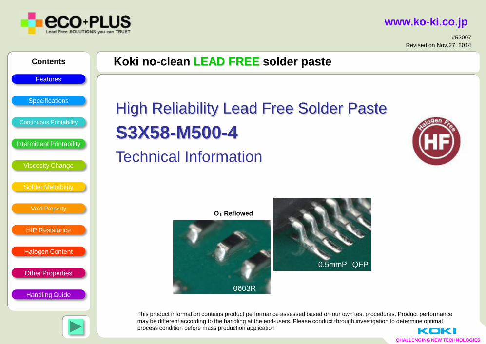
Koki no-clean LEAD FREE solder paste
This product information contains product performance assessed based on our own test procedures. Product performance
may be different according to the handling at the end-users. Please conduct through investigation to determine optimal
process condition before mass production application
#52007
Revised on Nov.27, 2014
High Reliability Lead Free Solder Paste
S3X58-M500-4
Technical Information
Contents
Features
Specifications
Continuous Printability
Viscosity Change
Intermittent Printability
Solder Meltability
Void Property
Handling Guide
HIP Resistance
Halogen Content
Other Properties
0603R
0.5mmP QFP
O₂ Reflowed
CHALLENGING NEW TECHNOLOGIES
2
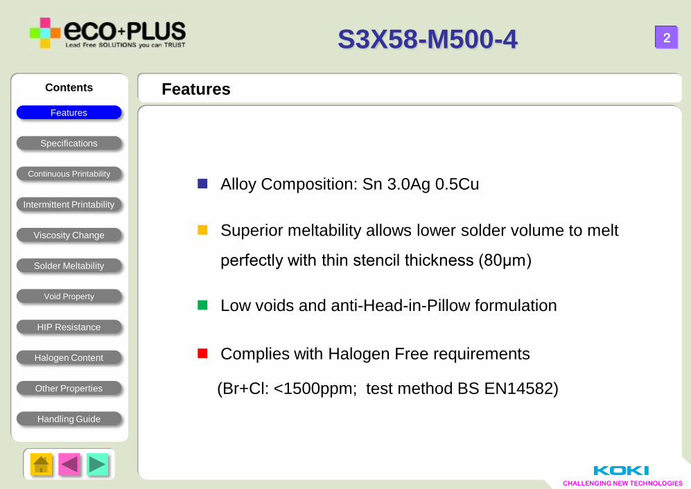
Alloy Composition: Sn 3.0Ag 0.5Cu
Superior meltability allows lower solder volume to melt
perfectly with thin stencil thickness (80μm)
Low voids and anti-Head-in-Pillow formulation
Complies with Halogen Free requirements
(Br+Cl: <1500ppm; test method BS EN14582)
Features
S3X58-M500-4
Contents
Specifications
Continuous Printability
Viscosity Change
Intermittent Printability
Solder Meltability
Void Property
Handling Guide
HIP Resistance
Halogen Content
Other Properties
Features
CHALLENGING NEW TECHNOLOGIES
3
Specifications
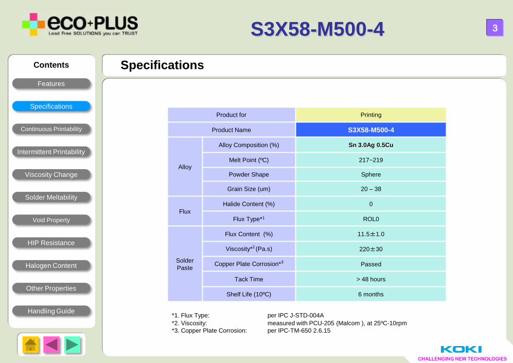
*1. Flux Type: per IPC J-STD-004A
*2. Viscosity: measured with PCU-205 (Malcom ), at 25ºC-10rpm
*3. Copper Plate Corrosion: per IPC-TM-650 2.6.15
Product for Printing
Product Name S3X58-M500-4
Alloy
Alloy Composition (%) Sn 3.0Ag 0.5Cu
Melt Point (ºC) 217~219
Powder Shape Sphere
Grain Size (um) 20 – 38
Flux
Halide Content (%) 0
Flux Type*1 ROL0
Solder
Paste
Flux Content (%) 11.5±1.0
Viscosity*2 (Pa.s) 220±30
Copper Plate Corrosion*3 Passed
Tack Time > 48 hours
Shelf Life (10ºC) 6 months
S3X58-M500-4
Contents
Features
Continuous Printability
Viscosity Change
Intermittent Printability
Solder Meltability
Void Property
Handling Guide
HIP Resistance
Halogen Content
Other Properties
Specifications
CHALLENGING NEW TECHNOLOGIES
4
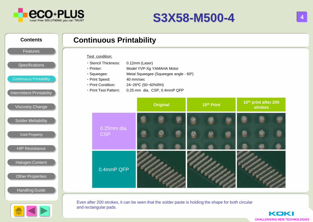
Continuous Printability
Test condition:
・ Stencil Thickness: 0.12mm (Laser)
・ Printer: Model YVP-Xg YAMAHA Motor
・ Squeegee: Metal Squeegee (Squeegee angle - 60º)
・ Print Speed: 40 mm/sec
・ Print Condition: 24~26ºC (50~60%RH)
・ Print Test Pattern: 0.25 mm dia. CSP, 0.4mmP QFP
Even after 200 strokes, it can be seen that the solder paste is holding the shape for both circular
and rectangular pads.
S3X58-M500-4
Original 10th Print 10th print after 200
strokes
0.25mm dia.
CSP
0.4mmP QFP
Contents
Features
Specifications
Viscosity Change
Intermittent Printability
Solder Meltability
Void Property
Handling Guide
HIP Resistance
Halogen Content
Other Properties
Continuous Printability
CHALLENGING NEW TECHNOLOGIES
5
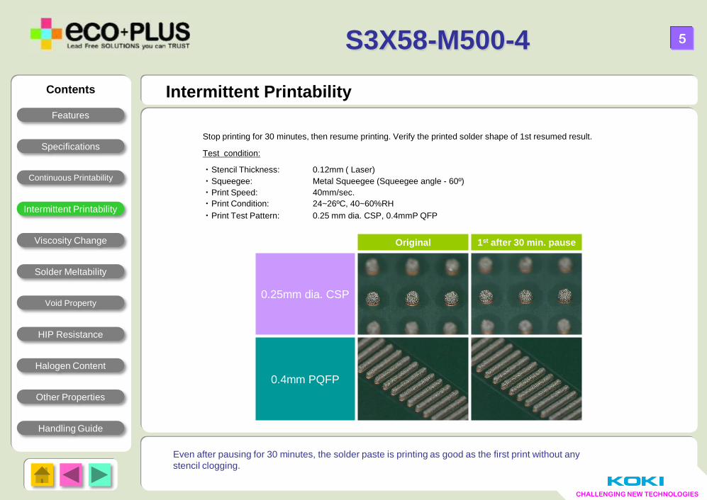
Intermittent Printability
Even after pausing for 30 minutes, the solder paste is printing as good as the first print without any
stencil clogging.
S3X58-M500-4
Stop printing for 30 minutes, then resume printing. Verify the printed solder shape of 1st resumed result.
Test condition:
・Stencil Thickness: 0.12mm ( Laser)
・Squeegee: Metal Squeegee (Squeegee angle - 60º)
・Print Speed: 40mm/sec.
・Print Condition: 24~26ºC, 40~60%RH
・Print Test Pattern: 0.25 mm dia. CSP, 0.4mmP QFP
Original 1st after 30 min. pause
0.25mm dia. CSP
0.4mm PQFP
Contents
Features
Specifications
Continuous Printability
Viscosity Change
Solder Meltability
Void Property
Handling Guide
HIP Resistance
Halogen Content
Other Properties
Intermittent Printability
CHALLENGING NEW TECHNOLOGIES
6
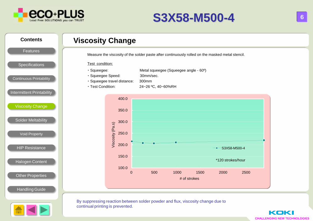
Viscosity Change
Measure the viscosity of the solder paste after continuously rolled on the masked metal stencil.
Test condition:
・ Squeegee: Metal squeegee (Squeegee angle - 60º)
・ Squeegee Speed: 30mm/sec.
・ Squeegee travel distance: 300mm
・ Test Condition: 24~26 ºC, 40~60%RH
By suppressing reaction between solder powder and flux, viscosity change due to
continual printing is prevented.
*120 strokes/hour
S3X58-M500-4
100.0
150.0
200.0
250.0
300.0
350.0
400.0
0 500 1000 1500 2000 2500
Vis
cosity
(Pa.s
)
# of strokes
S3X58-M500-4
Contents
Features
Specifications
Continuous Printability
Intermittent Printability
Solder Meltability
Void Property
Handling Guide
HIP Resistance
Halogen Content
Other Properties
Viscosity Change
CHALLENGING NEW TECHNOLOGIES
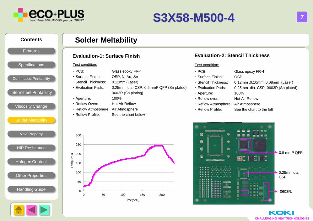
Test condition:
・ PCB: Glass epoxy FR-4
・ Surface Finish: OSP, Ni-Au, Sn
・ Stencil Thickness: 0.12mm (Laser)
・ Evaluation Pads: 0.25mm dia. CSP, 0.5mmP QFP (Sn plated)
0603R (Sn plating)
・ Aperture: 100%
・ Reflow Oven: Hot Air Reflow
・ Reflow Atmosphere: Air Atmosphere
・ Reflow Profile: See the chart below・
Solder Meltability
7
0
50
100
150
200
250
300
0 50 100 150 200
Tem
p. (º
C)
Time(sec.)
S3X58-M500-4
0603R.
0.5 mmP QFP
0.25mm dia.
CSP
Contents
Features
Specifications
Continuous Printability
Viscosity Change
Intermittent Printability
Void Property
Handling Guide
HIP Resistance
Halogen Content
Other Properties
Solder Meltability
Test condition:
・ PCB: Glass epoxy FR-4
・ Surface Finish: OSP
・ Stencil Thickness: 0.12mm ,0.10mm, 0.08mm (Laser)
・ Evaluation Pads: 0.25mm dia. CSP, 0603R (Sn plated)
・ Aperture: 100%
・ Reflow oven: Hot Air Reflow
・ Reflow Atmosphere: Air Atmosphere
・ Reflow Profile: See the chart to the left
Evaluation-1: Surface Finish Evaluation-2: Stencil Thickness
CHALLENGING NEW TECHNOLOGIES
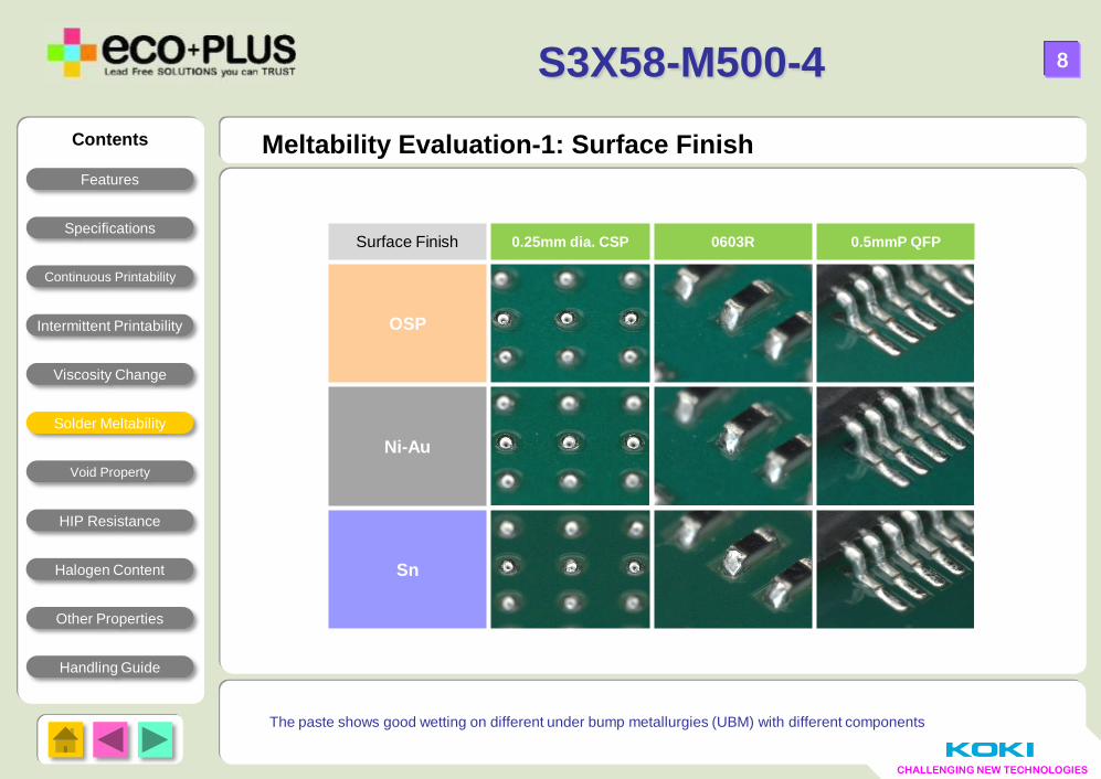
Meltability Evaluation-1: Surface Finish
8
The paste shows good wetting on different under bump metallurgies (UBM) with different components
S3X58-M500-4
Surface Finish 0.25mm dia. CSP 0603R 0.5mmP QFP
OSP
Ni-Au
Sn
Contents
Features
Specifications
Continuous Printability
Viscosity Change
Intermittent Printability
Void Property
Handling Guide
HIP Resistance
Halogen Content
Other Properties
Solder Meltability
CHALLENGING NEW TECHNOLOGIES
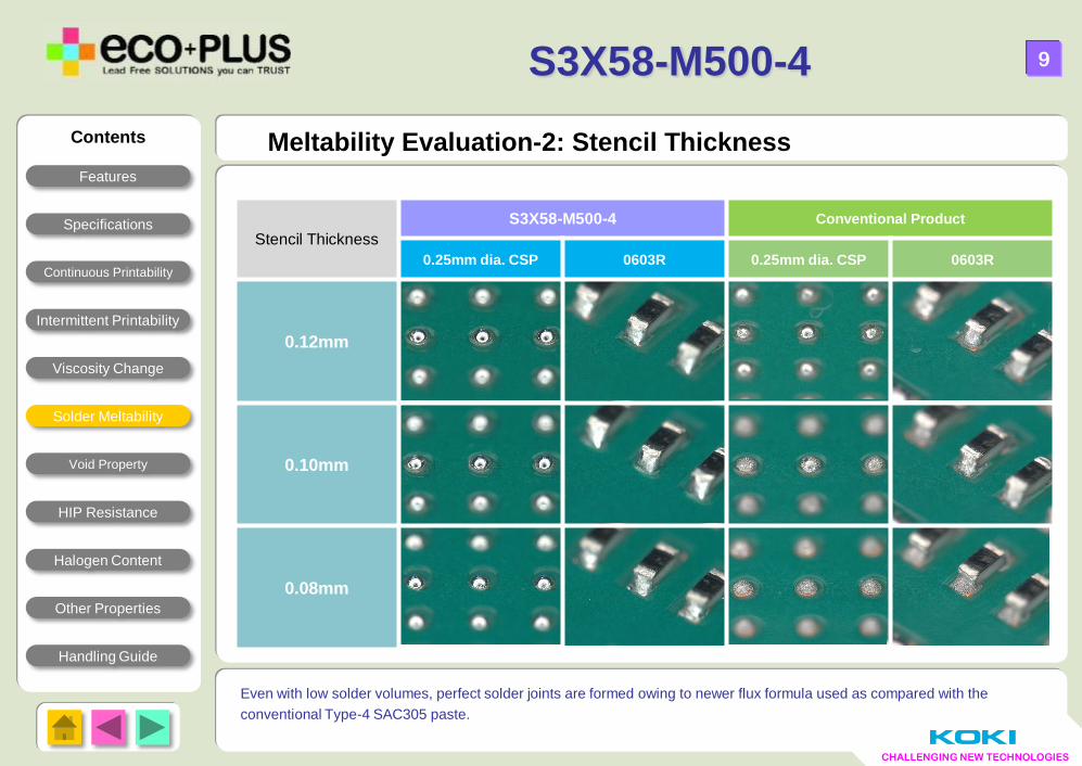
Meltability Evaluation-2: Stencil Thickness
9
Even with low solder volumes, perfect solder joints are formed owing to newer flux formula used as compared with the
conventional Type-4 SAC305 paste.
S3X58-M500-4
Contents
Features
Specifications
Continuous Printability
Viscosity Change
Intermittent Printability
Void Property
Handling Guide
HIP Resistance
Halogen Content
Other Properties
Solder Meltability
Stencil Thickness
S3X58-M500-4 Conventional Product
0.25mm dia. CSP 0603R 0.25mm dia. CSP 0603R
0.12mm
0.10mm
0.08mm
CHALLENGING NEW TECHNOLOGIES
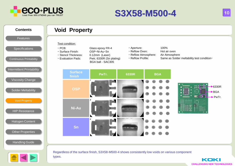
Void Property
Test condition:
・ PCB: Glass epoxy FR-4
・ Surface Finish: OSP・Ni-Au・Sn
・ Stencil Thickness: 0.12mm (Laser)
・ Evaluation Pads: Pwtr, 6330R (Sn plating)
BGA ball - SAC305
10
Regardless of the surface finish, S3X58-M500-4 shows consistently low voids on various component
types.
S3X58-M500-4
Contents
Features
Specifications
Continuous Printability
Viscosity Change
Intermittent Printability
Solder Meltability
Handling Guide
HIP Resistance
Halogen Content
Other Properties
Void Property
Surface
finish PwTr. 6330R BGA
OSP
Ni-Au
Sn
PwTr.
6330R
BGA
・ Aperture: 100%
・ Reflow Oven: Hot air oven
・ Reflow Atmosphere: Air Atmosphere
・ Reflow Profile: Same as Solder meltability test condition・
CHALLENGING NEW TECHNOLOGIES
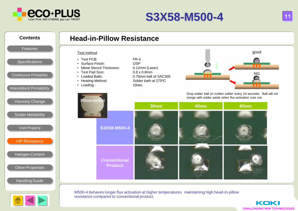
M500-4 behaves longer flux activation at higher temperatures maintaining high head-in-pillow resistance compared to conventional product.
Head-in-Pillow Resistance
Test method
• Test PCB: FR-4
• Surface Finish: OSP
• Metal Stencil Thickness: 0.12mm (Laser)
• Test Pad Size: 0.8 x 0.8mm
• Loaded Balls: 0.76mm ball of SAC305
• Heating Method: Solder bath at 275ºC
• Loading : 10sec.
good
NG
Drop solder ball on molten solder every 10 seconds. Ball will not
merge with solder paste when flux activation runs out.
30sec 40sec 60sec
S3X58-M500-4
Conventional
Product
Pillow defect
S3X58-M500-4
11
Contents
Features
Specifications
Continuous Printability
Viscosity Change
Intermittent Printability
Solder Meltability
Void Property
Handling Guide
Halogen Content
Other Properties
HIP Resistance
CHALLENGING NEW TECHNOLOGIES
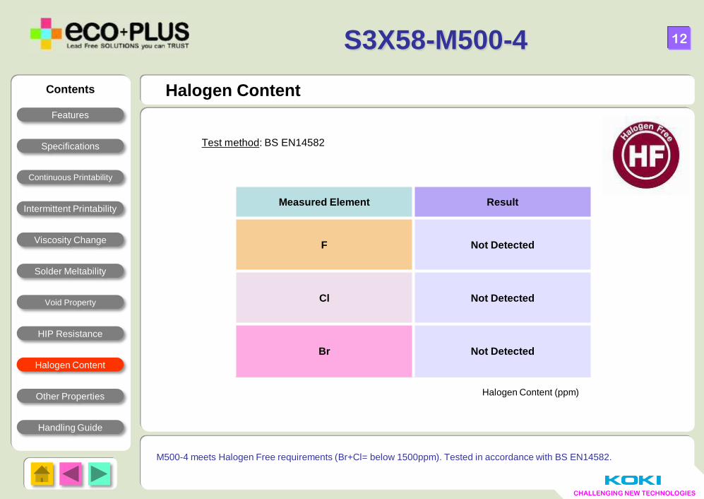
Halogen Content
12
M500-4 meets Halogen Free requirements (Br+Cl= below 1500ppm). Tested in accordance with BS EN14582.
Halogen Content (ppm)
Measured Element Result
F Not Detected
Cl Not Detected
Br Not Detected
Test method: BS EN14582
S3X58-M500-4
Contents
Features
Specifications
Continuous Printability
Viscosity Change
Intermittent Printability
Solder Meltability
Void Property
Handling Guide
HIP Resistance
Other Properties
Halogen Content
CHALLENGING NEW TECHNOLOGIES
13
S3X58-M500-4
Other Properties Contents
Features
Specifications
Continuous Printability
Viscosity Change
Intermittent Printability
Solder Meltability
Void Property
Handling Guide
HIP Resistance
Halogen Content
Other Properties
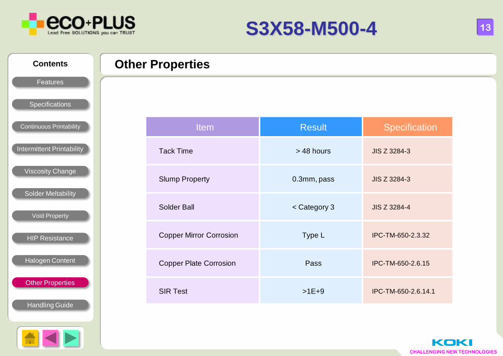
Item Result Specification
Tack Time > 48 hours JIS Z 3284-3
Slump Property 0.3mm, pass JIS Z 3284-3
Solder Ball < Category 3 JIS Z 3284-4
Copper Mirror Corrosion Type L IPC-TM-650-2.3.32
Copper Plate Corrosion Pass IPC-TM-650-2.6.15
SIR Test >1E+9 IPC-TM-650-2.6.14.1
CHALLENGING NEW TECHNOLOGIES
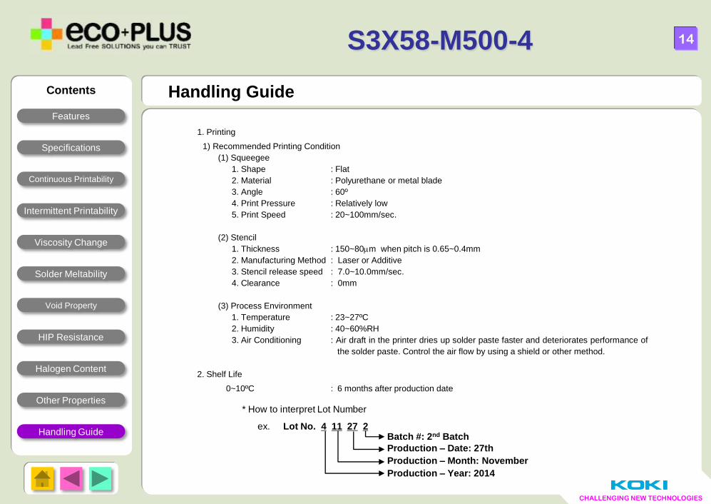
1. Printing
1) Recommended Printing Condition
(1) Squeegee
1. Shape : Flat
2. Material : Polyurethane or metal blade
3. Angle : 60º
4. Print Pressure : Relatively low
5. Print Speed : 20~100mm/sec.
(2) Stencil
1. Thickness : 150~80m when pitch is 0.65~0.4mm
2. Manufacturing Method : Laser or Additive
3. Stencil release speed : 7.0~10.0mm/sec.
4. Clearance : 0mm
(3) Process Environment
1. Temperature : 23~27ºC
2. Humidity : 40~60%RH
3. Air Conditioning : Air draft in the printer dries up solder paste faster and deteriorates performance of
the solder paste. Control the air flow by using a shield or other method.
2. Shelf Life
0~10ºC : 6 months after production date
* How to interpret Lot Number
ex. Lot No. 4 11 27 2 Batch #: 2nd Batch
Production – Date: 27th
Production – Month: November
Production – Year: 2014
Handling Guide
14
S3X58-M500-4
Contents
Features
Specifications
Continuous Printability
Viscosity Change
Intermittent Printability
Solder Meltability
Void Property
HIP Resistance
Halogen Content
Other Properties
Handling Guide
CHALLENGING NEW TECHNOLOGIES
15
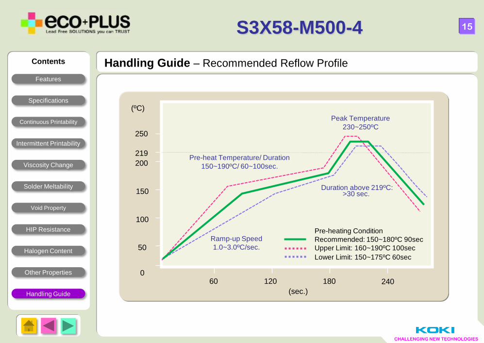
Handling Guide – Recommended Reflow Profile
S3X58-M500-4
Pre-heat Temperature/ Duration
150~190ºC/ 60~100sec.
Peak Temperature
230~250ºC
Ramp-up Speed
1.0~3.0ºC/sec.
180 240
(sec.)
Duration above 219ºC:
>30 sec.
120 60
250
100
150
50
0
Pre-heating Condition
Recommended: 150~180ºC 90sec
Upper Limit: 160~190ºC 100sec
Lower Limit: 150~175ºC 60sec
219
200
(ºC)
Contents
Features
Specifications
Continuous Printability
Viscosity Change
Intermittent Printability
Solder Meltability
Void Property
HIP Resistance
Halogen Content
Other Properties
Handling Guide
CHALLENGING NEW TECHNOLOGIES
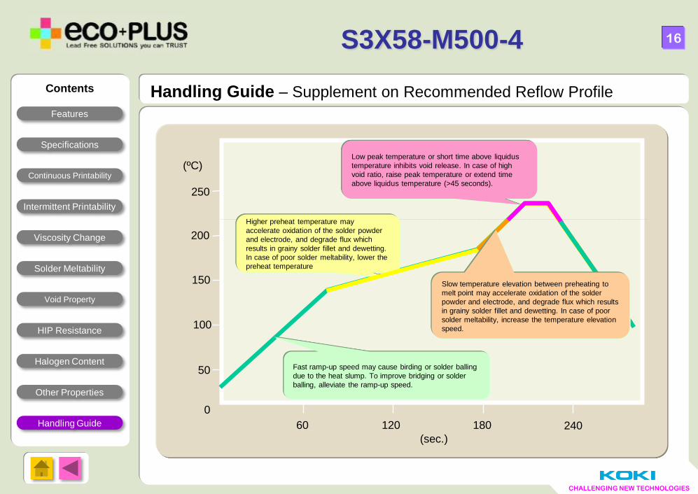
(sec.) 180 240 120 60
200
250
100
150
50
0
(ºC)
Fast ramp-up speed may cause birding or solder balling
due to the heat slump. To improve bridging or solder
balling, alleviate the ramp-up speed.
Higher preheat temperature may
accelerate oxidation of the solder powder
and electrode, and degrade flux which
results in grainy solder fillet and dewetting.
In case of poor solder meltability, lower the
preheat temperature
Low peak temperature or short time above liquidus
temperature inhibits void release. In case of high
void ratio, raise peak temperature or extend time
above liquidus temperature (>45 seconds).
Slow temperature elevation between preheating to
melt point may accelerate oxidation of the solder
powder and electrode, and degrade flux which results
in grainy solder fillet and dewetting. In case of poor
solder meltability, increase the temperature elevation
speed.
16
(sec.)
S3X58-M500-4
Contents
Features
Specifications
Continuous Printability
Viscosity Change
Intermittent Printability
Solder Meltability
Void Property
HIP Resistance
Halogen Content
Other Properties
Handling Guide
Handling Guide – Supplement on Recommended Reflow Profile
Recommended