February 2007
CA08101001E For more information visit:
www.eaton.com
Contents
Loadcenters & Circuit Breakers 3-1
3
Lo
ad
cen
ters
&C
ircu
it B
reakers
Description Page
Type CH Loadcenters and Circuit Breakers
Product Description . . . . . . . . . . . . . . . . . . . . . . . . . . . . . . . . . . . . . . . . . . .
3-2
Application Description . . . . . . . . . . . . . . . . . . . . . . . . . . . . . . . . . . . . . . . .
3-3
Standards and Certifications . . . . . . . . . . . . . . . . . . . . . . . . . . . . . . . . . . . .
3-3
Features, Benefits and Functions . . . . . . . . . . . . . . . . . . . . . . . . . . . . . . . .
3-5
Product Specifications . . . . . . . . . . . . . . . . . . . . . . . . . . . . . . . . . . . . . . . . .
3-6
Product Selection . . . . . . . . . . . . . . . . . . . . . . . . . . . . . . . . . . . . . . . . . . . . .
3-8
Loadcenters . . . . . . . . . . . . . . . . . . . . . . . . . . . . . . . . . . . . . . . . . . . . . . .
3-8
Spa Panels . . . . . . . . . . . . . . . . . . . . . . . . . . . . . . . . . . . . . . . . . . . . . . . .
3-15
Surge Loadcenter . . . . . . . . . . . . . . . . . . . . . . . . . . . . . . . . . . . . . . . . . .
3-18
Renovation Loadcenter. . . . . . . . . . . . . . . . . . . . . . . . . . . . . . . . . . . . . .
3-20
CH Retrofit Interior Kits. . . . . . . . . . . . . . . . . . . . . . . . . . . . . . . . . . . . . .
3-21
Loadcenter Accessories . . . . . . . . . . . . . . . . . . . . . . . . . . . . . . . . . . . . .
3-23
Circuit Breakers . . . . . . . . . . . . . . . . . . . . . . . . . . . . . . . . . . . . . . . . . . . .
3-29
Circuit Breaker Accessories . . . . . . . . . . . . . . . . . . . . . . . . . . . . . . . . . .
3-35
Technical Data and Specifications . . . . . . . . . . . . . . . . . . . . . . . . . . . . . . .
3-37
Type BR Loadcenters and Circuit Breakers
Product Description . . . . . . . . . . . . . . . . . . . . . . . . . . . . . . . . . . . . . . . . . . .
3-39
Application Description . . . . . . . . . . . . . . . . . . . . . . . . . . . . . . . . . . . . . . . .
3-40
Standards and Certifications . . . . . . . . . . . . . . . . . . . . . . . . . . . . . . . . . . . .
3-40
Features, Benefits and Functions . . . . . . . . . . . . . . . . . . . . . . . . . . . . . . . .
3-41
Product Specifications . . . . . . . . . . . . . . . . . . . . . . . . . . . . . . . . . . . . . . . . .
3-42
Product Selection . . . . . . . . . . . . . . . . . . . . . . . . . . . . . . . . . . . . . . . . . . . . .
3-44
Loadcenters . . . . . . . . . . . . . . . . . . . . . . . . . . . . . . . . . . . . . . . . . . . . . . .
3-44
Catalog Numbering System . . . . . . . . . . . . . . . . . . . . . . . . . . . . . . . . . .
3-45
Spa Panels . . . . . . . . . . . . . . . . . . . . . . . . . . . . . . . . . . . . . . . . . . . . . . . .
3-54
Riser Panels . . . . . . . . . . . . . . . . . . . . . . . . . . . . . . . . . . . . . . . . . . . . . . .
3-58
BR Retrofit Interior Kits . . . . . . . . . . . . . . . . . . . . . . . . . . . . . . . . . . . . . .
3-59
Renovation Loadcenters . . . . . . . . . . . . . . . . . . . . . . . . . . . . . . . . . . . . .
3-61
Loadcenter Accessories . . . . . . . . . . . . . . . . . . . . . . . . . . . . . . . . . . . . .
3-62
Circuit Breakers . . . . . . . . . . . . . . . . . . . . . . . . . . . . . . . . . . . . . . . . . . . .
3-64
Circuit Breaker Accessories . . . . . . . . . . . . . . . . . . . . . . . . . . . . . . . . . .
3-73
Technical Data and Specifications . . . . . . . . . . . . . . . . . . . . . . . . . . . . . . .
3-75
Type CH and BR Cross-Reference
. . . . . . . . . . . . . . . . . . . . . . . . . . . . . . . . . .
3-78
Classified Circuit Breakers
. . . . . . . . . . . . . . . . . . . . . . . . . . . . . . . . . . . . . . . .
3-80
OEM Loadcenter Interiors
. . . . . . . . . . . . . . . . . . . . . . . . . . . . . . . . . . . . . . . .
3-83
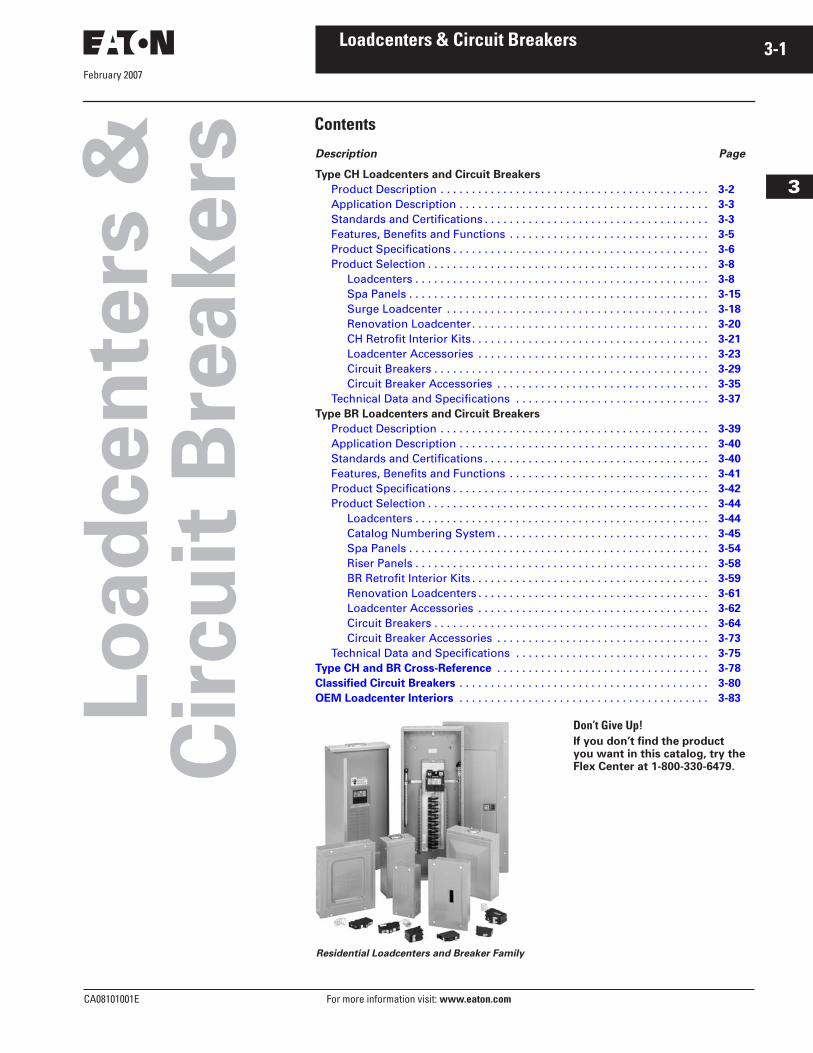
Residential Loadcenters and Breaker Family
Don’t Give Up!If you don’t find the product you want in this catalog, try the Flex Center at 1-800-330-6479.
February 2007
3-2
For more information visit:
www.eaton.com
CA08101001E
Loadcenters & Circuit Breakers
3
Type CH Loadcenters & Circuit Breakers
Product Description
Product Description
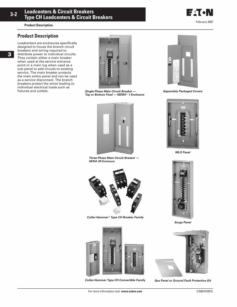
Loadcenters are enclosures specifically designed to house the branch circuit breakers and wiring required to distribute power to individual circuits. They contain either a main breaker when used at the service entrance point or a main lug when used as a sub-panel to add circuits to existing service. The main breaker protects the main entire panel and can be used as a service disconnect. The branch breakers protect the wires leading to individual electrical loads such as fixtures and outlets.
Single-Phase Main Circuit Breaker —
Top or Bottom Feed — NEMA
�
1 Enclosure
Three-Phase Main Circuit Breaker —
NEMA 3R Enclosure
Cutler-Hammer
�
Type CH Breaker Family
Cutler-Hammer Type CH Convertible Family
Separately Packaged Covers
MLO Panel
Surge Panel
Spa Panel or Ground Fault Protection Kit
February 2007
CA08101001E For more information visit:
www.eaton.com
3-3Loadcenters & Circuit Breakers
3
Type CH Loadcenters & Circuit Breakers
Application Description
Application Description
Loadcenter Construction
Cutler-Hammer Type CH loadcenters by Eaton Corporation feature silver flash plated copper bus in all interiors. Fingers are rated 200 amperes throughout the CH line. Therefore, the sum of the handle ratings connected to any one stab is limited to 200 amperes maximum. NEMA 1 boxes are manu-factured from cold rolled 16 gauge sheet steel. Raintight boxes are manufactured from galvanized steel. All boxes and trims are finished using an electrostatic powder coat, baked urethane paint process.
Neutrals
Cutler-Hammer Type CH loadcenters feature three types of neutrals:
Factory-Bonded Split Neutral
Single-phase main circuit breaker panels are supplied with a factory-bonded twin neutral. When used as a sub-panel, the bonding strap should be removed, and the bonding screw should be reinstalled. The bonded side is now the ground, and the un-bonded side is the neutral. When used as a service entrance panel, the unused neutral holes on either side may be used for terminating ground wires.
Insulated Split Neutral
Most single-phase main lug panels (12 circuits and greater) are supplied with a twin neutral with an insulated cross strap. These panels are shipped in an un-bonded state. For service entrance applications, the neutral must be bonded utilizing the bonding strap supplied with the panel. For sub-feed applications, the panel may be installed as is. Separate ground bars are provided on these panels.
Insulated/Bondable Single Neutral
When a panel is supplied with a single neutral, it arrives from the factory in an “unbonded” state. All that is required to bond the neutral in a service entrance application is to loosen the bonding screw and the neutral screw directly beside it, insert the bonding strap into the neutral bar, and re-tighten both connections. The single neutral can be moved by the contractor to the other side of the panel, if desired. In a service entrance application, where the neutral is bonded, unused neutral connections may be used for the termination of equipment grounds.
Grounds
In service entrance applications where the neutral is bonded, unused neutral holes may be used for terminating ground conductors. In sub-feed pan-els, the neutral must be isolated (non-bonded), and ground wires must be terminated on a separate ground bar.
The Factory Bonded Split Neutral panels have sufficient terminations for both ground and neutral conduc-tors. The Insulated Split Neutral panels are supplied with a separate factory-installed ground bar. Insulated/Bondable Single Neutral panels are supplied without a ground bar (unless otherwise noted), and ground bar kits if needed must be purchased separately.
Surge Protectors
The CHSURGE Surge Protector has indicating lights that indicate when the units should be replaced. The CHSA01 and CHSA03 Surge Protectors inter-nally short, causing the circuit breaker feeding the surge protector to trip. All but the CHSURGE Surge Protector should be wired to the load side of 15 or 20 ampere feeder circuit breakers mounted adjacent to the main incom-ing device.
The CHSPULTRA Cutler-Hammer Home Surge Protector is an externally mounted TVSS unit that provides industrial level surge protection in a residential design.
The CHSPULTRA is also available factory installed in the loadcenter and carries a lifetime warranty.
Standards and Certifications
UL
�
Listings
All Cutler-Hammer Type CH loadcenters by are listed under UL File E8741.
Neutral and Ground Terminals
The standard terminals on groundsand neutrals are rated to accept (3) — #14 – #10 Cu/Al or (1) — #14 – 4 wires. For larger cables, add-on neutral lugs may be ordered from the accessories on
Pages 3-23
and
3-24
.
Note:
NEC
�
allows only one current carrying conductor per hole on neutrals unless otherwise noted.
Bottom-Fed Loadcenters
When the power cable is brought into the loadcenter from below the panel; then the main lug panels, and single-phase, 225 amperes and below, load-centers can be rotated 180 degrees to allow straight-in wiring of power cables to the main terminals. Because the CSR main circuit breaker handle operates horizontally, the orientation of the main circuit breaker handle is consistent with the requirements of NEC Article 240-81.
Gutter Splicing
Loadcenters are not UL listed as wiring troughs. Therefore, gutter splicing of riser cables to tap off to the main device is not permitted. Refer to NEC Article 373-8.
Fire Rating
Due to the numerous openings in both loadcenter boxes and trims, they should not be mounted in firewalls. There is no approval method for sealing the enclosures for this application.
Date Code
The date of manufacture of each load-center is printed on the outside of the carton as well as inside the loadcenter. On the carton, the date code is printed on the end carton label. In the load-center, the date code is located on the small white label located on the right side wall (with the main device on top).
The date code is in the following for-mat: F # # # &. The “F” is the numeric code for the Lincoln, IL plant, and the three numbers are the year and week of manufacture e.g., 023. The “&” sign at the end signifies the decade of the 2000s. Therefore, the date code F023& would indicate that the product was manufactured in the 23rd week of 2000. The 1980s are represented by a “+” sign and the 1990s are represented by a “=” at the end of the code.
February 2007
3-4
For more information visit:
www.eaton.com
CA08101001E
Loadcenters & Circuit Breakers
3
Type CH Loadcenters & Circuit Breakers
Standards and Certifications
Plug-on Type CH Breakers
Description
Quick-make, quick-break switch mech-anism combined with inverse time ele-ment tripping operation and trip-free handle design. Type CH circuit break-ers trip to the OFF position eliminating nuisance callbacks. The thermal-magnetic trip curve avoids nuisance tripping on mild overloads while react-ing almost instantaneously to severe short circuit conditions. Multipole breakers have internal common trip connection to operate all poles simul-taneously. Handles are marked with ON-OFF indication and ampere rating of the breaker. Type CH breakers meet UL Standard 489, NEMA standards, and Federal Spec Classification W-C 375 b/Gen. They are UL listed under File Number E11713, E8741, E3624 and E51287: and CSA certified file number LR87196, except Type CHT breakers.
Type CH Circuit Breaker Ratings
Single- and double-pole CH breakers rated 15 and 20 amperes have low instantaneous magnetic trip levels. The 15 and 20 ampere breakers with “HM” suffix have high magnetic trip settings recommended for circuits with inherently high inrush currents. All Type CH breakers are marked for heating, air conditioning and refrigera-tion (HACR) equipment application. Single-pole 15 – 20 ampere breakers are also suitable for switching duty (SWD). Shunt trip coils operate on 120 Vac and require one additional pole space per breaker.
February 2007
CA08101001E For more information visit:
www.eaton.com
3-5Loadcenters & Circuit Breakers
3
Type CH Loadcenters & Circuit Breakers
Features, Benefits and Functions
Features, Benefits and Functions
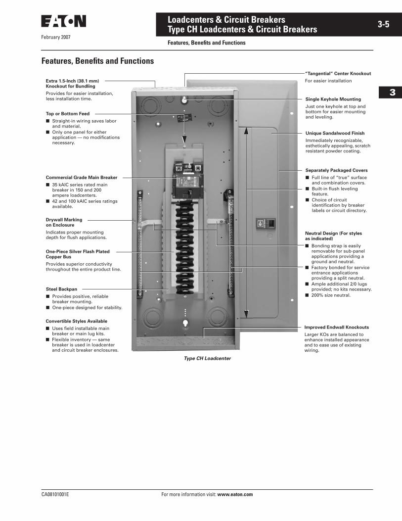
Type CH Loadcenter
Extra 1.5-Inch (38.1 mm)
Knockout for Bundling
Provides for easier installation,less installation time.
Top or Bottom Feed
■ Straight-in wiring saves labor and material.
■ Only one panel for eitherapplication — no modifications necessary.
Commercial Grade Main Breaker
■ 35 kAIC series rated main breaker in 150 and 200ampere loadcenters.
■ 42 and 100 kAIC series ratings available.
Steel Backpan
■ Provides positive, reliable breaker mounting.
■ One-piece designed for stability.
One-Piece Silver Flash Plated
Copper Bus
Provides superior conductivity throughout the entire product line.
Drywall Marking
on Enclosure
Indicates proper mountingdepth for flush applications.
Single Keyhole Mounting
Just one keyhole at top andbottom for easier mounting and leveling.
Unique Sandalwood Finish
Immediately recognizable, esthetically appealing, scratch resistant powder coating.
Neutral Design (For styles
as indicated)
■ Bonding strap is easily removable for sub-panel applications providing a ground and neutral.
■ Factory bonded for service entrance applications providing a split neutral.
■ Ample additional 2/0 lugs provided; no kits necessary.
■ 200% size neutral.
Separately Packaged Covers
■ Full line of “true” surface and combination covers.
■ Built-in flush leveling feature.
■ Choice of circuit identification by breaker labels or circuit directory.
Improved Endwall Knockouts
Larger KOs are balanced to enhance installed appearance and to ease use of existing wiring.
Convertible Styles Available
■ Uses field installable main breaker or main lug kits.
■ Flexible inventory — same breaker is used in loadcenter and circuit breaker enclosures.
“Tangential” Center Knockout
For easier installation
February 2007
3-6
For more information visit:
www.eaton.com
CA08101001E
Loadcenters & Circuit Breakers
3
Type CH Loadcenters & Circuit Breakers
Product Specifications
Product Specifications
General
A. The Contractor shall furnish and install loadcenters incorporating circuit breakers of the number, rating and type as specified herein and as shown on the contract drawings.
B. The loadcenter and all compo-nents shall be designed, manufac-tured and tested in accordance with the latest applicable stan-dards of UL and NEMA including:
1. UL 67 — Standards for Panelboards
2. UL 50 — Standards for Cabinetsand Boxes
3. UL 489 — Standards for Molded Case Circuit Breakers
4. Federal Spec ClassificationW-C 375
5. UL 1699 — All Fault Interrupting
Qualifications
A. The manufacturer of the loadcenter shall be the manufacturer of the circuit breaker within the load cen-ter. All breakers shall be full size.
B. For the equipment specified herein, the manufacturer shall be ISO
�
9000 certified.
C. The manufacturer of this equip-ment shall have produced similar electrical equipment for a mini-mum period of seven (7) years.
Manufacturers
A. Eaton
Ratings
A. Loadcenters shall be rated for 240 Vac and shall have short circuit ratings as shown on the drawings or as herein scheduled, but not less than 10,000 amperes rms symmetrical.
B. Breakers shall be full size and a minimum of 125 ampere frame. Breakers 10 through 125 ampere trip size shall take up the same pole spacing.
C. Loadcenters shall be labeled witha UL short circuit rating. When series ratings are applied with integral or remote devices, a label shall be provided. Series ratings shall cover all trip ratings of installed frames. It shall state the conditions of the UL series ratings including:
1. Size and type of upstream device.
2. Branch devices that can be used.
3. UL series short circuit rating.
Construction
A. All interiors, with the exception of the branch circuit breakers shall be completely factory assembled with main breakers, main lugs or no main device.
B. Interiors shall be so designed that circuit breakers can be replaced without disturbing adjacent units and without removing the main bus connectors and shall be so designed that circuits may be changed without machining,drilling or tapping.
C. Physical means must be provided to prevent the installation of more overcurrent devices than that number for which the enclosure was designed. Full size breakers are required.
Bus
A. Bus bars for the main and cross connectors shall be of silver flash plated copper construction in accordance with UL standards. Bussing shall be braced to 65 kAIC.
B. Neutral bussing shall have a suit-able lug for each outgoing feeder requiring a neutral connection of same ampacity as branch.
Wiring/Termination
A. All wire connectors and terminals shall be of the anti-turn solderless type and suitable for copper or aluminum wire of the sizes indi-cated. All connectors shall meet the “Requirements for Wire Connectors and Soldering Lugs” UL 486B.
B. All loadcenters where marked shall be suitable for use with 60/75°C rated wire.
Circuit Breakers
A. Circuit breakers shall be molded case type, 3/4-inch (19.1 mm) wide per pole. Multipole circuit breakers shall be of a stack pole design to provide electrical phase isolation and have an internal common trip.
B. Each pole of the circuit breaker will have inverse time delay overload and instantaneous short circuit protection by means of both ther-mal and magnetic sensors. Circuit breakers shall be quick-make/quick-break.
C. The circuit breaker calibration shall not be affected by environ-mental changes in relative humid-ity. Breakers shall be calibrated after assembly.
D. All circuit breakers shall be oper-ated by a toggle-type handle and multipole circuit breakers shall have an internal common trip mechanism. The circuit breakers shall incorporate trip mechanisms that are mechanically trip-free from the handle. The handle position shall provide good visual trip indication.
E. Contacts shall be of non-weldingsilver alloy.
F. All branch breaker handles shall be of a different color than the case of the breaker.
G. All terminals shall be listed for use with copper or aluminum conduc-tors. Terminals shall be of the box lug design. The terminals shall meet UL 486B requirements and shall be suitable for use with either 60° or 75°C wire.
H. Breakers shall be SWD rated and/or HACR rated as required.
I. Arc Fault Interrupting circuit breakers, (AFC), shall be provided on all 15 and 20 ampere single-phase 120/240 Vac circuits except those indicated as remote con-trolled breakers. AFI breakers shall be “Classified for mitigating the effects of arcing faults,” orconforming to UL Standard 1699 and as defined by per article 210-12 Section A of the 1999 NEC Code.
February 2007
CA08101001E For more information visit:
www.eaton.com
3-7Loadcenters & Circuit Breakers
3
Type CH Loadcenters & Circuit Breakers
Product Specifications
Enclosures
A. Loadcenters shall have NEMA 1 general purpose or NEMA 3R rain-proof enclosures as indicated on the drawings and shall be surface or flush mounted except where noted.
B. For indoor applications, enclo-sures shall be rated NEMA 1. Enclosures shall be manufactured from cold-rolled code-gauge sheet steel having multiple knockouts and painted per paint specifica-tion. For outdoor applications, enclosures shall be rated NEMA 3R. Enclosures shall be manufac-tured from galvanized steel which shall be painted per the painted as specified. Enclosures shall be of sufficient size to meet or exceed NEC wire bending space.
C. The cover shall have an easy adjustment feature for flush applications.
D. Boxes shall be factory assembled into a single rigid structure.
E. Provide circuit breaker marking labels and directories.
FinishA. Boxes and trims shall be finished
with a high scratch-resistant aes-thetically pleasing finish. The fin-ish shall be polyurethane coating electrostatically applied to a thick-ness of 1.8 to 2 mils.
B. All loadcenters shall be provided with provisions for accepting a paintable or wall paperable deco-rator accessory cover. Where loadcenters are installed in living areas, provide manufacturer designed and tested decoratorcover kits.
WarrantyThe minimum warranty for Residential loadcenters, breakers and surge pro-tection devices shall be as follows:
– Lifetime loadcenter warranty– Lifetime warranty on all Arc
Fault Circuit Interrupting Circuit Breakers
– Lifetime Warranty on CHSPULTRA including $5000 connected load warranty
– Lifetime warranty on all thermal magnetic and GFCI branch circuit breakers
– 1-year warranty on plug-in surge protection device(CHSURGE)
February 2007
3-8
For more information visit: www.eaton.com CA08101001E
Loadcenters & Circuit Breakers
3
Type CH Loadcenters & Circuit BreakersProduct Selection
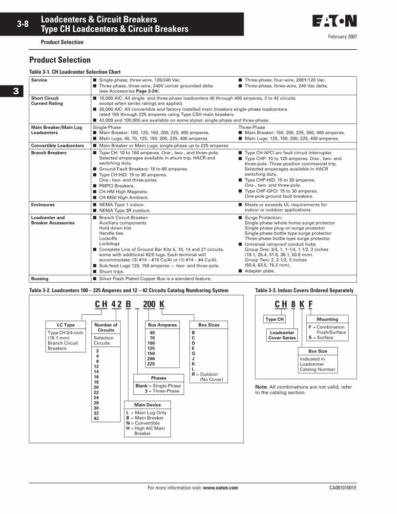
Product SelectionTable 3-1. CH Loadcenter Selection Chart
Table 3-2. Loadcenters 100 – 225 Amperes and 12 – 42 Circuits Catalog Numbering System
Service ■ Single-phase, three-wire, 120/240 Vac.■ Three-phase, three-wire, 240V corner grounded delta
(see Accessories Page 3-24).
■ Three-phase, four-wire, 208Y/120 Vac.■ Three-phase, three-wire, 240 Vac delta.
Short Circuit
Current Rating
■ 10,000 AIC: All single- and three-phase loadcenters 40 through 400 amperes, 2 to 42 circuits except when series ratings are applied.
■ 35,000 AIC: All convertible and factory installed main breakers single-phase loadcenters rated 150 through 225 amperes using Type CSH main breakers.
■ 42,000 and 100,000 are available on some styles: single-phase and three-phase.
Main Breaker/Main Lug
Loadcenters
Single-Phase■ Main Breaker: 100, 125, 150, 200, 225, 400 amperes.■ Main Lugs: 40, 70, 125, 150, 200, 225, 400 amperes.
Three-Phase■ Main Breaker: 150, 200, 225, 300, 400 amperes.■ Main Lugs: 125, 150, 200, 225, 400 amperes.
Convertible Loadcenters ■ Main Breaker or Main Lugs: single-phase up to 225 amperes
Branch Breakers ■ Type CH: 10 to 150 amperes. One-, two-, and three-pole.Selected amperages available in shunt trip, HACR andswitching duty.
■ Ground Fault Breakers: 15 to 60 amperes.■ Type CH-HID: 15 to 30 amperes.
One-, two- and three-poles.■ PMPCI Breakers.■ CH-HM High Magnetic.■ CH-M50 High Ambient.
■ Type CH-AFCI arc fault circuit interrupter.■ Type CHP: 10 to 125 amperes. One-, two- and
three-pole. Three-position commercial trip. Selected amperages available in HACR switching duty.
■ Type CHP-HID: 15 to 30 amperes.One-, two- and three-pole.
■ Type CHP-GFCI: 15 to 30 amperes.One-pole ground fault breakers.
Enclosures ■ NEMA Type 1 indoor.■ NEMA Type 3R outdoor.
■ Meets or exceeds UL requirements for indoor or outdoor applications.
Loadcenter and
Breaker Accessories
■ Branch Circuit Breaker:Auxiliary componentsHold down kitsHandle tiesLockoffsLockdogs
■ Complete Line of Ground Bar Kits 5, 10, 14 and 21 circuits,some with additional #2/0 lugs. Each terminal will accommodate: (3) #14 – #10 Cu/Al or (1) #14 – #4 Cu/Al.
■ Sub-feed Lugs 125, 150 amperes — two- and three-pole.■ Shunt trips.
■ Surge Protection:Single-phase whole home surge protectorSingle-phase plug-on surge protectorSingle-phase bottle type surge protectorThree-phase bottle type surge protector
■ Universal rainproof conduit hubsGroup One: 3/4, 1, 1-1/4, 1-1/2, 2 inches(19.1, 25.4, 31.8, 38.1, 50.8 mm).Group Two: 2, 2-1/2, 3 inches(50.8, 63.5, 76.2 mm).
■ Adapter plate.
Bussing ■ Silver Flash Plated Copper Bus is a standard feature.
C H 4 2 B 200 K
LC Type
Type CH 3/4-inch (19.1 mm)Branch CircuitBreakers
Number of
Circuits
SelectionCircuits
2
4
8
12
14
16
18
20
22
24
28
30
32
42
Main Device
L = Main Lug OnlyB = Main BreakerN = ConvertibleH = High AIC Main
Breaker
Bus Amperes
40
70
100
125
150
200
225
Phases
Blank = Single-Phase3 = Three-Phase
Box Sizes
B
C
D
E
G
J
K
L
R = Outdoor(No Cover)
Table 3-3. Indoor Covers Ordered Separately
Note: All combinations are not valid, refer to the catalog section.
C H 8 K FType CH
Box Size
Indicated in LoadcenterCatalog Number
Loadcenter
Cover Series
Mounting
F = CombinationFlush/Surface
S = Surface
February 2007
CA08101001E For more information visit: www.eaton.com
3-9Loadcenters & Circuit Breakers
3
Type CH Loadcenters & Circuit BreakersProduct Selection
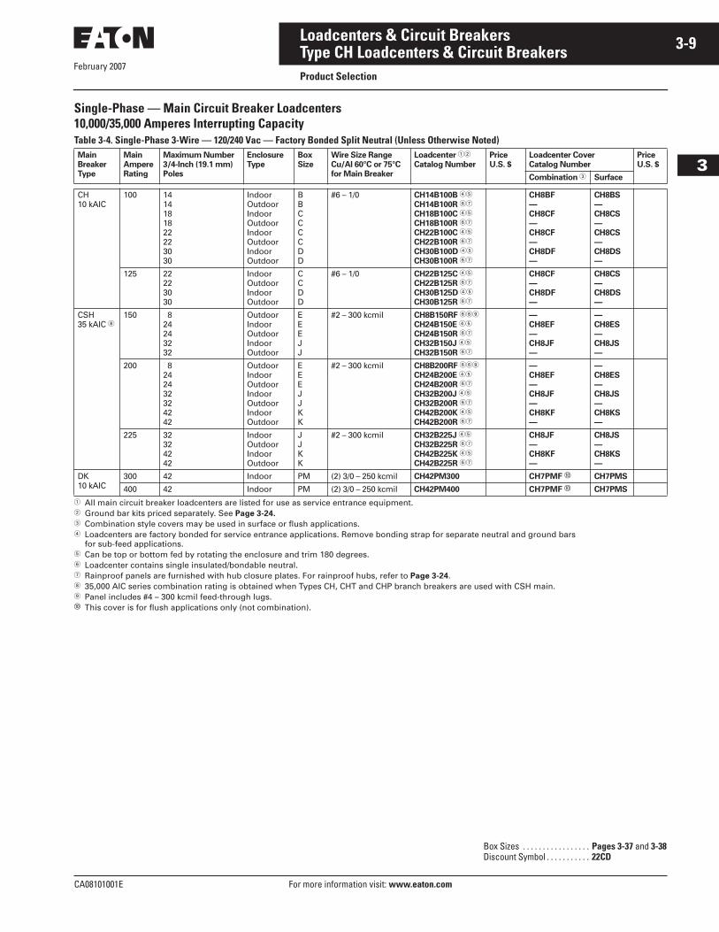
Single-Phase — Main Circuit Breaker Loadcenters10,000/35,000 Amperes Interrupting Capacity Table 3-4. Single-Phase 3-Wire — 120/240 Vac — Factory Bonded Split Neutral (Unless Otherwise Noted)
� All main circuit breaker loadcenters are listed for use as service entrance equipment.� Ground bar kits priced separately. See Page 3-24.� Combination style covers may be used in surface or flush applications.� Loadcenters are factory bonded for service entrance applications. Remove bonding strap for separate neutral and ground bars
for sub-feed applications.� Can be top or bottom fed by rotating the enclosure and trim 180 degrees.� Loadcenter contains single insulated/bondable neutral.� Rainproof panels are furnished with hub closure plates. For rainproof hubs, refer to Page 3-24. 35,000 AIC series combination rating is obtained when Types CH, CHT and CHP branch breakers are used with CSH main. Panel includes #4 – 300 kcmil feed-through lugs.� This cover is for flush applications only (not combination).
Main
Breaker
Type
Main
Ampere
Rating
Maximum Number
3/4-Inch (19.1 mm)
Poles
Enclosure
Type
Box
Size
Wire Size Range
Cu/Al 60°C or 75°C
for Main Breaker
Loadcenter ��
Catalog Number
Price
U.S. $
Loadcenter Cover
Catalog Number
Price
U.S. $
Combination � Surface
CH10 kAIC
100 1414181822223030
IndoorOutdoorIndoorOutdoorIndoorOutdoorIndoorOutdoor
BBCCCCDD
#6 – 1/0 CH14B100B ��
CH14B100R ��
CH18B100C ��
CH18B100R ��
CH22B100C ��
CH22B100R ��
CH30B100D ��
CH30B100R ��
CH8BF
—
CH8CF
—
CH8CF
—
CH8DF
—
CH8BS
—
CH8CS
—
CH8CS
—
CH8DS
—
—
—
—
—
125 22223030
IndoorOutdoorIndoorOutdoor
CCDD
#6 – 1/0 CH22B125C ��
CH22B125R ��
CH30B125D ��
CH30B125R ��
CH8CF
—
CH8DF
—
CH8CS
—
CH8DS
—
—
—
CSH35 kAIC
150 824243232
OutdoorIndoorOutdoorIndoorOutdoor
EEEJJ
#2 – 300 kcmil CH8B150RF ��
CH24B150E ��
CH24B150R ��
CH32B150J ��
CH32B150R ��
—
CH8EF
—
CH8JF
—
—
CH8ES
—
CH8JS
—
—
—
—
200 8242432324242
OutdoorIndoorOutdoorIndoorOutdoorIndoorOutdoor
EEEJJKK
#2 – 300 kcmil CH8B200RF ��
CH24B200E ��
CH24B200R ��
CH32B200J ��
CH32B200R ��
CH42B200K ��
CH42B200R ��
—
CH8EF
—
CH8JF
—
CH8KF
—
—
CH8ES
—
CH8JS
—
CH8KS
—
—
—
—
—
225 32324242
IndoorOutdoorIndoorOutdoor
JJKK
#2 – 300 kcmil CH32B225J ��
CH32B225R ��
CH42B225K ��
CH42B225R ��
CH8JF
—
CH8KF
—
CH8JS
—
CH8KS
—
—
—
DK10 kAIC
300 42 Indoor PM (2) 3/0 – 250 kcmil CH42PM300 CH7PMF � CH7PMS
400 42 Indoor PM (2) 3/0 – 250 kcmil CH42PM400 CH7PMF � CH7PMS
Box Sizes . . . . . . . . . . . . . . . . . Pages 3-37 and 3-38Discount Symbol . . . . . . . . . . . 22CD
February 2007
3-10
For more information visit: www.eaton.com CA08101001E
Loadcenters & Circuit Breakers
3
Type CH Loadcenters & Circuit BreakersProduct Selection
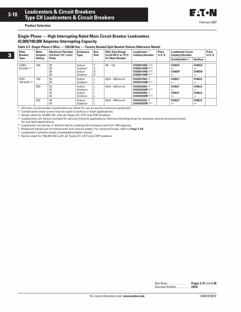
Single-Phase — High Interrupting Rated Main Circuit Breaker Loadcenters42,000/100,000 Amperes Interrupting CapacityTable 3-5. Single-Phase 3-Wire — 120/240 Vac — Factory Bonded Split Neutral (Unless Otherwise Noted)
� All main circuit breaker loadcenters are listed for use as service entrance equipment.� Combination style covers may be used in surface or flush applications.� Series rated for 42,000 AIC with all Types CH, CHT and CHP breakers.� Loadcenters are factory bonded for service entrance applications. Remove bonding strap for separate neutral and ground bars
for sub-feed applications.� Loadcenter can be top or bottom fed by rotating the enclosure and trim 180 degrees.� Rainproof panels are furnished with hub closure plates. For rainproof hubs, refer to Page 3-24. � Loadcenter contains single insulated/bondable neutral. Series rated for 100,000 AIC with all Types CH, CHT and CHP breakers.
Main
Breaker
Type
Main
Ampere
Rating
Maximum Number
3/4-Inch (19.1 mm)
Poles
Enclosure
Type
Box
Size
Wire Size Range
Cu/Al 60°C or 75°C
for Main Breaker
Loadcenter �
Catalog Number
Price
U.S. $
Loadcenter Cover
Catalog Number
Price
U.S. $
Combination � Surface
CHB442 kAIC �
100 20202828
IndoorOutdoorIndoorOutdoor
CCDD
#6 – 1/0 CH20H100C ��
CH20H100R ��
CH28H100D ��
CH28H100R ��
CH8CF
—
CH8DF
—
CH8CS
—
CH8DS
—
—
—
CHH100 kAIC
150 3232
IndoorOutdoor
LL
#2/0 – 300 kcmil CH32H150L �
CH32H150R ��CH8LF
—
CH8LS
— —
200 32324242
IndoorOutdoorIndoorOutdoor
LLLL
#2/0 – 300 kcmil CH32H200L �
CH32H200R ��
CH42H200L �
CH42H200R ��
CH8LF
—
CH8LF
—
CH8LS
—
CH8LS
—
—
—
225 4242
IndoorOutdoor
LL
#2/0 – 300 kcmil CH42H225L �
CH42H225R ��CH8LF
—
CH8LS
— —
Box Sizes . . . . . . . . . . . . . . . . . Pages 3-37 and 3-38Discount Symbol . . . . . . . . . . 22CD
February 2007
CA08101001E For more information visit: www.eaton.com
3-11Loadcenters & Circuit Breakers
3
Type CH Loadcenters & Circuit BreakersProduct Selection
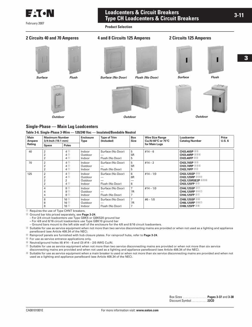
2 Circuits 40 and 70 Amperes 4 and 8 Circuits 125 Amperes 2 Circuits 125 Amperes
Single-Phase — Main Lug LoadcentersTable 3-6. Single-Phase 3-Wire — 120/240 Vac — Insulated/Bondable Neutral
� Requires the use of Type CHNT breakers.� Ground bar kits priced separately, see Page 3-24.
– For 2/4 circuit loadcenters use Type GBK5 or GBK520 ground bar– For 4/8 and 8/16 circuit loadcenters use Type GBK10 ground bar– Ground bars mount to the left side wall of the enclosure for the 4/8 and 8/16 circuit loadcenters.
� Suitable for use as service equipment when not more than two service disconnecting mains are provided or when not used as a lighting and appliance panelboard (see Article 408.34 of the NEC).
� Rainproof panels are furnished with hub closure plates. For rainproof hubs, refer to Page 3-24.� For use as service entrance applications only.� Neutral/ground holes (6) #14 – 6 and (3) #14 – 2/0 AWG Cu/AI.� Suitable for use as service equipment when not more than two service disconnecting mains are provided or when not more than six service
disconnecting mains are provided and when not used as a lighting and appliance panelboard (see Article 408.34 of the NEC). Suitable for use as service equipment when a main breaker is used or when not more than six service disconnecting mains are provided and when not
used as a lighting and appliance panelboard (see Article 408.34 of the NEC).
Outdoor
Surface Flush
Outdoor
Surface (No Door) Flush (No Door)
Outdoor
Surface Flush
Main
Ampere
Rating
Maximum Number
3/4-Inch (19.1 mm)
Enclosure
Type
Type of Trim
(Included)
Box
Size
Wire Size Range
Cu/Al 60°C or 75°C
for Main Lugs
Loadcenter
Catalog Number
Price
U.S. $
Space Poles
40 222
4 �
4 �
4 �
IndoorOutdoorIndoor
Surface (No Door)—Flush (No Door)
55R5
#14 – 6 CH2L40SP ��
CH2L40RP ���
CH2L40FP ��
70 222
4 �4 �
4 �
IndoorOutdoorIndoor
Surface (No Door)—Flush (No Door)
55R5
#14 – 2 CH2L70SP ��
CH2L70RP ���
CH2L70FP ��
125 2222
4 �
4 �
24 �
IndoorOutdoorOutdoorIndoor
Surface (No Door)——Flush (No Door)
66R—6
#14 – 1/0 CH2L125SP ��
CH2L125RP ���
CH2L125RSE2P ���
CH2L125FP ��
444
8 �
8 �
8 �
IndoorOutdoorIndoor
Surface (No Door)—Flush (No Door)
77R7
#14 – 1/0 CH4L125SP ��
CH4L125RP ���
CH4L125FP ��
888
16 �
16 �
16 �
IndoorOutdoorIndoor
Surface (No Door)—Flush (No Door)
77R7
#6 – 1/0 CH8L125SP �
CH8L125RP ���
CH8L125FP �
Box Sizes . . . . . . . . . . . . . . . . . Pages 3-37 and 3-38Discount Symbol . . . . . . . . . . . 22CD
February 2007
3-12
For more information visit: www.eaton.com CA08101001E
Loadcenters & Circuit Breakers
3
Type CH Loadcenters & Circuit BreakersProduct Selection
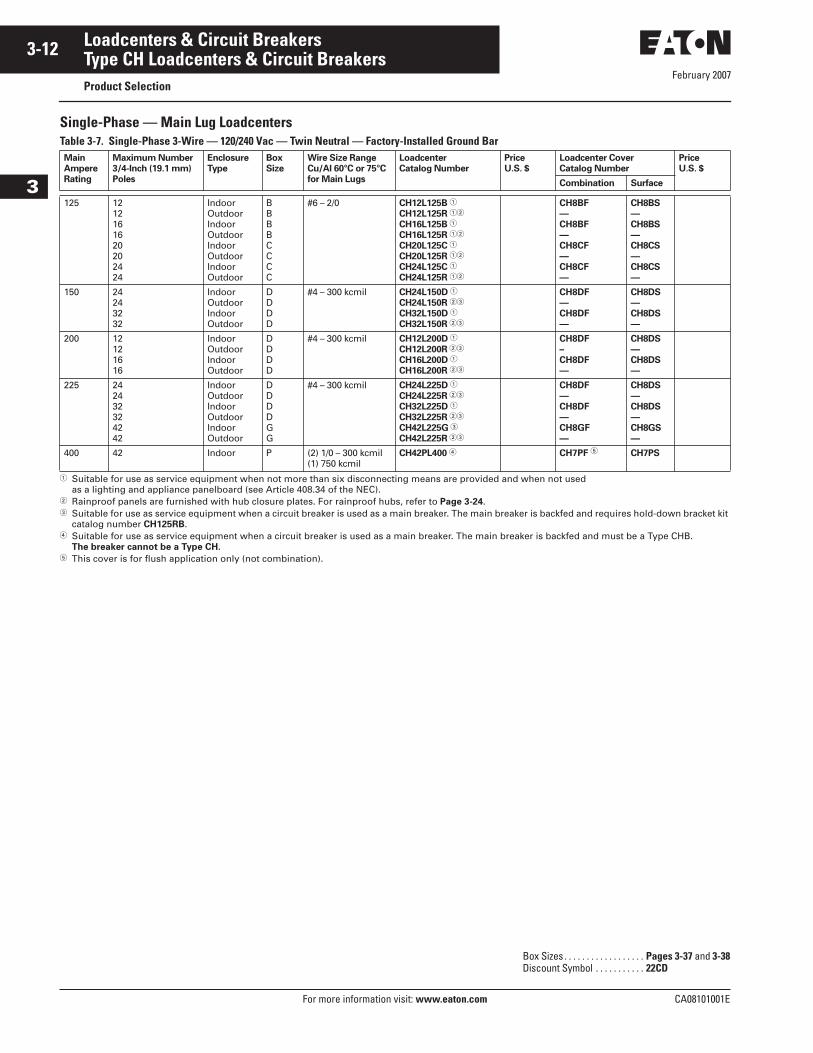
Single-Phase — Main Lug LoadcentersTable 3-7. Single-Phase 3-Wire — 120/240 Vac — Twin Neutral — Factory-Installed Ground Bar
� Suitable for use as service equipment when not more than six disconnecting means are provided and when not usedas a lighting and appliance panelboard (see Article 408.34 of the NEC).
� Rainproof panels are furnished with hub closure plates. For rainproof hubs, refer to Page 3-24.� Suitable for use as service equipment when a circuit breaker is used as a main breaker. The main breaker is backfed and requires hold-down bracket kit
catalog number CH125RB.� Suitable for use as service equipment when a circuit breaker is used as a main breaker. The main breaker is backfed and must be a Type CHB.
The breaker cannot be a Type CH.� This cover is for flush application only (not combination).
Main
Ampere
Rating
Maximum Number
3/4-Inch (19.1 mm)
Poles
Enclosure
Type
Box
Size
Wire Size Range
Cu/Al 60°C or 75°C
for Main Lugs
Loadcenter
Catalog Number Price
U.S. $
Loadcenter Cover
Catalog Number
Price
U.S. $
Combination Surface
125 1212161620202424
IndoorOutdoorIndoorOutdoorIndoorOutdoorIndoorOutdoor
BBBBCCCC
#6 – 2/0 CH12L125B �
CH12L125R ��
CH16L125B �
CH16L125R ��
CH20L125C �
CH20L125R ��
CH24L125C �
CH24L125R ��
CH8BF
—
CH8BF
—
CH8CF
—
CH8CF
—
CH8BS
—
CH8BS
—
CH8CS
—
CH8CS
—
—
—
—
—
150 24243232
IndoorOutdoorIndoorOutdoor
DDDD
#4 – 300 kcmil CH24L150D �
CH24L150R ��
CH32L150D �
CH32L150R ��
CH8DF
—
CH8DF
—
CH8DS
—
CH8DS
—
—
—
200 12121616
IndoorOutdoorIndoorOutdoor
DDDD
#4 – 300 kcmil CH12L200D �
CH12L200R ��
CH16L200D �
CH16L200R ��
CH8DF
–
CH8DF
—
CH8DS
—
CH8DS
—
—
—
225 242432324242
IndoorOutdoorIndoorOutdoorIndoorOutdoor
DDDDGG
#4 – 300 kcmil CH24L225D �
CH24L225R ��
CH32L225D �
CH32L225R ��
CH42L225G �
CH42L225R ��
CH8DF
—
CH8DF
—
CH8GF
—
CH8DS
—
CH8DS
—
CH8GS
—
—
—
—
400 42 Indoor P (2) 1/0 – 300 kcmil(1) 750 kcmil
CH42PL400 � CH7PF � CH7PS
Box Sizes . . . . . . . . . . . . . . . . . . Pages 3-37 and 3-38Discount Symbol . . . . . . . . . . . 22CD
February 2007
CA08101001E For more information visit: www.eaton.com
3-13Loadcenters & Circuit Breakers
3
Type CH Loadcenters & Circuit BreakersProduct Selection
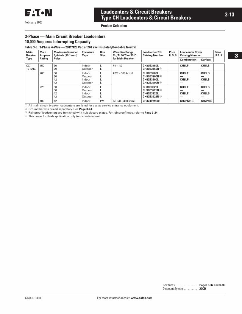
3-Phase — Main Circuit Breaker Loadcenters 10,000 Amperes Interrupting CapacityTable 3-8. 3-Phase 4-Wire — 208Y/120 Vac or 240 Vac Insulated/Bondable Neutral
� All main circuit breaker loadcenters are listed for use as service entrance equipment.� Ground bar kits priced separately. See Page 3-24.� Rainproof loadcenters are furnished with hub closure plates. For rainproof hubs, refer to Page 3-24.� This cover for flush application only (not combination).
Main
Breaker
Type
Main
Ampere
Rating
Maximum Number
3/4-Inch (19.1 mm)
Poles
Enclosure
Type
Box
Size Wire Size Range
Cu/Al 60°C or 75°C
for Main Breaker
Loadcenter ��
Catalog Number
Price
U.S. $
Loadcenter Cover
Catalog Number
Price
U.S. $
Combination Surface
CC10 kAIC
150 3030
IndoorOutdoor
LL
#1 – 4/0 CH30B3150L
CH30B3150R �CH8LF
—
CH8LS
— —
200 30304242
IndoorOutdoorIndoorOutdoor
LLLL
#2/0 – 300 kcmil CH30B3200L
CH30B3200R �
CH42B3200L
CH42B3200R �
CH8LF
—
CH8LF
—
CH8LS
—
CH8LS
—
—
—
225 30304242
IndoorOutdoorIndoorOutdoor
LLLL
CH30B3225L
CH30B3225R �
CH42B3225L
CH42B3225R �
CH8LF
—
CH8LF
—
CH8LS
—
CH8LS
—
—
—
400 42 Indoor PM (2) 3/0 – 350 kcmil CH424PM400 CH7PMF � CH7PMS
Box Sizes . . . . . . . . . . . . . . . . . Pages 3-37 and 3-38Discount Symbol . . . . . . . . . . . 22CD
February 2007
3-14
For more information visit: www.eaton.com CA08101001E
Loadcenters & Circuit Breakers
3
Type CH Loadcenters & Circuit BreakersProduct Selection
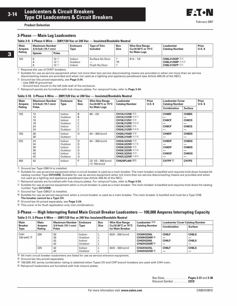
3-Phase — Main Lug LoadcentersTable 3-9. 3-Phase 4-Wire — 208Y/120 Vac or 240 Vac — Insulated/Bondable Neutral
� Requires the use of CHNT breakers.� Suitable for use as service equipment when not more than two service disconnecting means are provided or when not more than six service
disconnecting means are provided and when not used as a lighting and appliance panelboard (see Article 408.34 of the NEC).� Ground bar kits priced separately, see Page 3-24.
– Use GBK10 ground bar– Ground bars mount to the left side wall of the enclosure.
� Rainproof panels are furnished with hub closure plates. For rainproof hubs, refer to Page 3-24.
Table 3-10. 3-Phase 4-Wire — 208Y/120 Vac or 240 Vac — Insulated/Bondable Neutral
� Ground bar Type GBK14 is installed.� Suitable for use as service equipment when a circuit breaker is used as a main breaker. The main breaker is backfed and requires hold-down bracket kit
catalog number Type CH125RB. Suitable for use as service equipment when not more than six service disconnecting means are provided and when not used as a lighting and appliance panelboard (see Article 408.34 of the NEC).
� Rainproof panels are furnished with hub closure plates. For rainproof hubs, refer to Page 3-24. Suitable for use as service equipment when a circuit breaker is used as a main breaker. The main breaker is backfed and requires hold-down kit catalog
number Type CH125RB. Ground bar Type GBK21 is installed.� Suitable for use as service equipment when a circuit breaker is used as a main breaker. The main breaker is backfed and must be a Type CHB.
The breaker cannot be a Type CH.� Ground bar kit priced separately, see Page 3-24.� This cover is for flush application only (not combination).
3-Phase — High Interrupting Rated Main Circuit Breaker Loadcenters — 100,000 Amperes Interrupting CapacityTable 3-11. 3-Phase 4-Wire — 208Y/120 Vac or 240 Vac Insulated/Bondable Neutral
� All main circuit breaker loadcenters are listed for use as service entrance equipment.� Ground bar kits priced separately.� 100,000 AIC series combination rating is obtained when Types CH and CHP branch breakers are used with CHH main.� Rainproof loadcenters are furnished with hub closure plates.
Main
Ampere
Rating
Maximum Number
3/4-Inch (19.1 mm)
Enclosure
Type
Type of Trim
Included
Box
Size
Wire Size Range
Cu/Al 60°C or 75°C
for Main Lugs
Loadcenter
Catalog Number
Price
U.S. $
Spaces Poles
125 666
12 �
12 �
12 �
IndoorOutdoorIndoor
Surface No Door—Flush No Door
77R7
#14 – 1/0 CH6L3125SP ��
CH6L3125RP ���
CH6L3125FP ��
Main
Ampere
Rating
Maximum Number
3/4-Inch (19.1 mm)
Poles
Enclosure
Type
Box
Size
Wire Size Range
Cu/Al 60°C or 75°C
for Main Lugs
Loadcenter
Catalog Number
Price
U.S. $
Loadcenter Cover
Catalog Number
Price
U.S. $
Combination Surface
125 121218182424
IndoorOutdoorIndoorOutdoorIndoorOutdoor
BBCCCC
#6 – 2/0 CH12L3125B ��
CH12L3125R ���
CH18L3125C ��
CH18L3125R ��
CH24L3125C ��
CH24L3125R ��
CH8BF
—
CH8CF
—
CH8CF
—
CH8BS
—
CH8CS
—
CH8CS
—
—
—
—
150 3030
IndoorOutdoor
D #4 – 300 kcmil CH30L3150D ��
CH30L3150R ��CH8DF
—
CH8DS
— —
225 242430304242
IndoorOutdoorIndoorOutdoorIndoorOutdoor
DDDDGG
#4 – 300 kcmil CH24L3225D ��
CH24L3225R ��
CH30L3225D ��
CH30L3225R ��
CH42L3225G
CH42L3225R �
CH8DF
—
CH8DF
—
CH8GF
—
CH8DS
—
CH8DS
—
CH8GS
—
—
—
—
400 42 Indoor P (2) 1/0 – 300 kcmil(1) 750 kcmil
CH424PL400 �� CH7PF � CH7PS
Main
Breaker
Type
Main
Ampere
Rating
Maximum Number
3/4-Inch (19.1 mm)
Poles
Enclosure
Type
Box
Size
Wire Size Range
Cu/Al 60°C or 75°C
for Main Breaker
Loadcenter ��
Catalog Number
Loadcenter Cover Catalog Number
Combination Surface
CHH100 kAIC �
200 30304242
IndoorOutdoorIndoorOutdoor
LLLL
#2/0 – 300 kcmil CH30H3200L
CH30H3200R �
CH42H3200L
CH42H3200R �
CH8LF
—
CH8LF
—
CH8LS
—
CH8LS
—
225 4242
IndoorOutdoor
LL
#2/0 – 300 kcmil CH42H3225L
CH42H3225R �CH8LF
—
CH8LS
—
Box Sizes . . . . . . . . . . . . . . . . . Pages 3-37 and 3-38Discount Symbol . . . . . . . . . . 22CD
CA08101001E For more information visit: www.eaton.com
3-15Loadcenters & Circuit Breakers
February 2007
3
Type CH Loadcenters & Circuit BreakersProduct Selection
Convertible Loadcenters MCB or MLO — Base Units and Main Devices
Spa PanelsTable 3-14. Spa Panels Single-Phase 3-Wire — 120/240 Vac Insulated/Bondable Neutral —Factory Installed Ground Bar
� Includes a CH230GFI breaker, factory installed, and 2 extra circuits for convenience.� Includes a CH240GFI breaker, factory installed, and 2 extra circuits for convenience.� Includes a CH250GFI breaker, factory installed, and 2 extra circuits for convenience.� Includes a CH260GFI breaker, factory installed, and 2 extra circuits for convenience.
MainAmpereRating
CircuitBreakerIncluded
EnclosureType
Type of TrimIncluded
BoxSize
Wire Size RangeCu/Al 60°C or 75°Cfor Main Lugs
CatalogNumber
PriceU.S. $
30405060
CH230GFCH240GFCH250GFCH260GF
OutdoorOutdoorOutdoorOutdoor
————
5R5R5R5R
#14 – 1/0#14 – 1/0#14 – 1/0#14 – 1/0
CH30SPA �
CH40SPA �
CH50SPA �
CH60SPA �
10,000/35,000 Amperes Interrupting CapacityComplete assembly consists of: Loadcenter, Cover, and either Main Breaker Kit or Main Lug Kit.
Table 3-12. Indoor — Single-Phase — 3-Wire — 120/240 V — Factory Bonded Split Neutral — Top or Bottom Feed
� Panel does not include main. Order main breaker or main lug kit separately.� Loadcenters are factory bonded for service entrance applications. Remove bonding strap for separate neutral and ground bars for sub-feed applications.� Hold down kit included.� 35,000 AIC series combination rating is obtained when Types CH, CHT and CHP branch breakers are used with CSR main.� CSH breakers include line lugs only as standard.Note: Interrupting rating depends on main circuit breaker selected.
Table 3-13. Outdoor — Single-Phase — 3-Wire — 120/240 V — Insulated/Bondable Neutral
� Panel does not include main. Order main breaker or main lug kit separately. Rainproof panels are furnished with hub closure plates. For rainproof hubs, refer to Page 3-24. Includes feed-through lugs for both phase and neutral conductors.� Hold down kit included.� 35,000 AIC series combination rating is obtained when Types CH, CHT and CHP branch breakers are used with CSR main.� CSH breakers include line lugs only as standard.
Maximum BoxSize
Loadcenter Boxand Panel
Loadcenter Cover MainLug Kit
Main Breaker Kit
MainAmpereRating
Numberof Single Poles
Catalog Number PriceU.S. $
Catalog ��
NumberPriceU.S. $
Combi-nation
Surface WireSize
CatalogNumber
PriceU.S. $
kAICRating
WireSize
CatalogNumber
PriceU.S. $
125 22 C CH22N125C CH8CF CH8CS #10 – 1/0 CHL125N 10 #10 – 1/0 CH2100N �
CH2125N �
200 32 J CH32N200J CH8JF CH8JS #4 – 300kcmil
CHL225N 25 #2 – 300kcmil
CSH2125N ��
CSH2150N ��
CSH2175N ��
CSH2200N ��
225 42 K CH42N225K CH8KF CH8KS #4 – 300kcmil
CHL225N 25 #2 – 300kcmil
CSH2125N ��
CSH2150N ��
CSH2175N ��
CSH2200N ��
CSH2225N ��
Maximum BoxSize
Loadcenter Boxand Panel
MainLug Kit
MainBreaker Kit
MainAmpereRating
Numberof SinglePoles
CatalogNumber �
PriceU.S. $
WireSize
CatalogNumber
PriceU.S. $
kAICRating
WireSize
CatalogNumber
PriceU.S. $
200 8 E CH8N200RF #4 – 300 kcmil CHL225N 25 #2 – 300 kcmil CSH2125NCSH2150NCSH2175NCSH2200N
125 22
C CH22N125R #10 – 1/0 CHL125N 10 #10 – 1/0 CH2100N �
CH2125N �
200 32
J CH32N200R #4 – 300 kcmil CHL225N 25 #2 – 300 kcmil CSH2125N ��
CSH2150N ��
CSH2175N ��
CSH2200N ��
225 42
K CH42N225R #4 – 300 kcmil CHL225N 25 #2 – 300 kcmil CSH2125N ��
CSH2150N ��
CSH2175N ��
CSH2200N ��
CSH2225N ��
Box Sizes . . . . . . . . . . . . . . . . . Pages 3-37 and 3-38Discount Symbol . . . . . . . . . . . 22CD
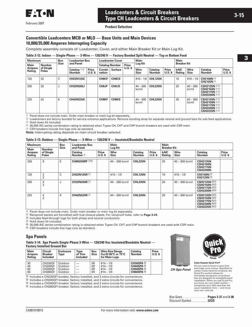
Cutler-Hammer Quick-ProSM
All you need to know to save time and make more money. Specified on certain Cutler-Hammer products, the Quick-Pro symbol allows for immediate recognition of products that are designed for straightforward installation. When you see Quick-Pro, you know you can install quickly — sometimes up to 50% less than the usual installation time — and move onto your next job.
CH Spa Panel
February 2007
3-16
For more information visit: www.eaton.com CA08101001E
Loadcenters & Circuit Breakers
3
Type CH Loadcenters & Circuit BreakersProduct Selection
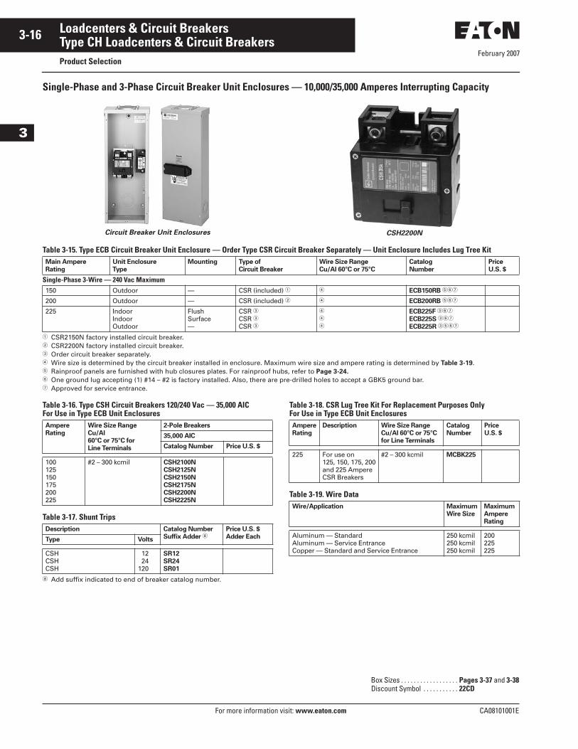
Single-Phase and 3-Phase Circuit Breaker Unit Enclosures — 10,000/35,000 Amperes Interrupting Capacity
Circuit Breaker Unit Enclosures CSH2200N
Table 3-15. Type ECB Circuit Breaker Unit Enclosure — Order Type CSR Circuit Breaker Separately — Unit Enclosure Includes Lug Tree Kit
� CSR2150N factory installed circuit breaker.� CSR2200N factory installed circuit breaker.� Order circuit breaker separately.� Wire size is determined by the circuit breaker installed in enclosure. Maximum wire size and ampere rating is determined by Table 3-19.� Rainproof panels are furnished with hub closures plates. For rainproof hubs, refer to Page 3-24.� One ground lug accepting (1) #14 – #2 is factory installed. Also, there are pre-drilled holes to accept a GBK5 ground bar.� Approved for service entrance.
Table 3-16. Type CSH Circuit Breakers 120/240 Vac — 35,000 AICFor Use in Type ECB Unit Enclosures
Table 3-17. Shunt Trips
Add suffix indicated to end of breaker catalog number.
Table 3-18. CSR Lug Tree Kit For Replacement Purposes OnlyFor Use in Type ECB Unit Enclosures
Table 3-19. Wire Data
Main Ampere
Rating
Unit Enclosure
Type
Mounting Type of
Circuit Breaker
Wire Size Range
Cu/Al 60°C or 75°C
Catalog
Number
Price
U.S. $
Single-Phase 3-Wire — 240 Vac Maximum150 Outdoor — CSR (included) � � ECB150RB ���
200 Outdoor — CSR (included) � � ECB200RB ���
225 IndoorIndoorOutdoor
FlushSurface—
CSR �CSR �CSR �
�
�
�
ECB225F ���
ECB225S ���
ECB225R ����
Ampere
Rating
Wire Size Range
Cu/Al
60°C or 75°C for
Line Terminals
2-Pole Breakers
35,000 AIC
Catalog Number Price U.S. $
100125150175200225
#2 – 300 kcmil CSH2100N
CSH2125N
CSH2150N
CSH2175N
CSH2200N
CSH2225N
Description Catalog Number
Suffix Adder Price U.S. $
Adder EachType Volts
CSHCSHCSH
1224
120
SR12
SR24
SR01
Ampere
Rating
Description Wire Size Range
Cu/Al 60°C or 75°C
for Line Terminals
Catalog
Number
Price
U.S. $
225 For use on 125, 150, 175, 200and 225 AmpereCSR Breakers
#2 – 300 kcmil MCBK225
Wire/Application Maximum
Wire Size
Maximum
Ampere
Rating
Aluminum — StandardAluminum — Service EntranceCopper — Standard and Service Entrance
250 kcmil250 kcmil250 kcmil
200225225
Box Sizes . . . . . . . . . . . . . . . . . . Pages 3-37 and 3-38Discount Symbol . . . . . . . . . . . 22CD
February 2007
CA08101001E For more information visit: www.eaton.com
3-17Loadcenters & Circuit Breakers
3
Type CH Loadcenters & Circuit BreakersProduct Selection
Table 3-20. Type ECC Circuit Breaker Unit Enclosure — Order Type CC Circuit Breaker Separately
� Order circuit breaker separately.� Wire size is determined by the circuit breaker installed in enclosure. Maximum wire size and ampere rating is determined by Table 3-22.� One ground lug accepting (1) #14 – #2 is factory installed. Also, there are pre-drilled holes to accept a GBK5 ground bar.� Approved for service entrance.� Rainproof panels are furnished with hub closures plates. For rainproof hubs, refer to Page 3-24.
Table 3-21. Type CC Circuit Breakers 240 Vac — 10,000 AICFor Use in Type ECC Unit Enclosures
Table 3-22. Wire Data
Table 3-23. Shunt Trips, Auxiliary and Alarm Contacts
� Add suffix indicated to end of breaker catalog number.
Main Ampere
Rating
Unit Enclosure
Type
Mounting Type of
Circuit Breaker
Wire Size Range
Cu/Al 60°C or 75°C
Catalog
Number
Price
U.S. $
Single-Phase 3-Wire — 240 Vac Maximum225225225
IndoorIndoorOutdoor
FlushSurface—
CC �CC �CC �
�
�
�
ECC225F ���
ECC225S ���
ECC225R ����
Ampere
Rating
Wire Size Range
Cu/Al
60°C or 75°C for
Line Terminals
Type CC
10,000 AIC
Catalog
Number
Price
U.S. $
2-Pole100125150
#4 – 4/0 CC2100
CC2125
CC2150
175200225
#2/0 – 300 kcmil CC2175
CC2200
CC2225
3-Pole100125150
#4 – 4/0 CC3100
CC3125
CC3150
175200225
#2/0 – 300 kcmil CC3175
CC3200
CC3225
Wire/Application Maximum
Wire Size
Maximum
Ampere
Rating
Aluminum — StandardAluminum — Service EntranceCopper — Standard and Service Entrance
250 kcmil250 kcmil250 kcmil
200225225
Description Catalog Number
Suffix Adder �Price U.S. $
Adder EachType Volts
Shunt TripCCCCCCCCCC
12 dc24 dc
120 ac208 ac240 ac
SR12
SR24
SR01
SR08
SR02
Auxiliary ContactCC (1) NO and (1) NC — AL1
Alarm ContactCSR — CR1
Box Sizes. . . . . . . . . . . . . . . . . . Pages 3-37 and 3-38Discount Symbol . . . . . . . . . . . 22CD
February 2007
3-18
For more information visit: www.eaton.com CA08101001E
Loadcenters & Circuit Breakers
3
Type CH Loadcenters & Circuit BreakersType CH Surge Loadcenters
Product Description
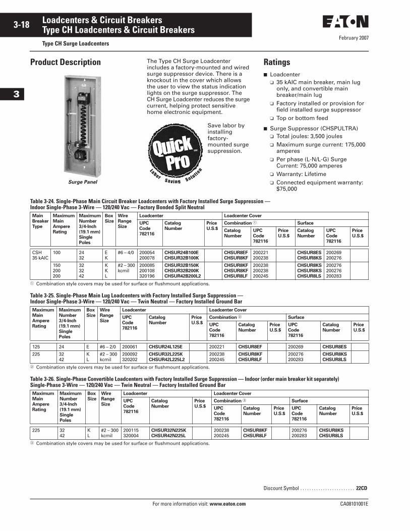
Surge Panel
The Type CH Surge Loadcenter includes a factory-mounted and wired surge suppressor device. There is a knockout in the cover which allows the user to view the status indication lights on the surge suppressor. The CH Surge Loadcenter reduces the surge current, helping protect sensitive home electronic equipment.
Ratings■ Loadcenter
❑ 35 kAIC main breaker, main lug only, and convertible main breaker/main lug
❑ Factory installed or provision for field installed surge suppressor
❑ Top or bottom feed
■ Surge Suppressor (CHSPULTRA)❑ Total joules: 3,500 joules❑ Maximum surge current: 175,000
amperes ❑ Per phase (L-N/L-G) Surge
Current: 75,000 amperes❑ Warranty: Lifetime❑ Connected equipment warranty:
$75,000
Table 3-24. Single-Phase Main Circuit Breaker Loadcenters with Factory Installed Surge Suppression — Indoor Single-Phase 3-Wire — 120/240 Vac — Factory Bonded Split Neutral
� Combination style covers may be used for surface or flushmount applications.
Table 3-25. Single-Phase Main Lug Loadcenters with Factory Installed Surge Suppression — Indoor Single-Phase 3-Wire — 120/240 Vac — Twin Neutral — Factory Installed Ground Bar
� Combination style covers may be used for surface or flushmount applications.
Table 3-26. Single-Phase Convertible Loadcenters with Factory Installed Surge Suppression — Indoor (order main breaker kit separately)Single-Phase 3-Wire — 120/240 Vac — Twin Neutral — Factory Installed Ground Bar
� Combination style covers may be used for surface or flushmount applications.
Save labor by installing factory-mounted surge suppression.
Main
Breaker
Type
Maximum
Main
Ampere
Rating
Maximum
Number
3/4-Inch
(19.1 mm)
Single
Poles
Box
Size
Wire
Range
Size
Loadcenter Loadcenter Cover
UPC
Code
782116
Catalog
Number
Price
U.S.$
Combination � Surface
Catalog
Number
UPC
Code
782116
Price
U.S.$
Catalog
Number
UPC
Code
782116
Price
U.S.$
CSH35 kAIC
100 2432
EK
#6 – 4/0 200054200078
CHSUR24B100E
CHSUR32B100K
CHSUR8EF
CHSUR8KF
200221200238
CHSUR8ES
CHSUR8KS
200269200276
150200200
323242
KKL
#2 – 300 kcmil
200085200108320196
CHSUR32B150K
CHSUR32B200K
CHSUR42B200L2
CHSUR8KF
CHSUR8KF
CHSUR8LF
200238200238200245
CHSUR8KS
CHSUR8KS
CHSUR8LS
200276200276200283
Maximum
Main
Ampere
Rating
Maximum
Number
3/4-Inch
(19.1 mm)
Single
Poles
Box
Size
Wire
Range
Size
Loadcenter Loadcenter Cover
UPC
Code
782116
Catalog
Number
Price
U.S.$
Combination � Surface
UPC
Code
782116
Catalog
Number
Price
U.S.$
UPC
Code
782116
Catalog
Number
Price
U.S.$
125 24 E #6 – 2/0 200061 CHSUR24L125E 200221 CHSUR8EF 200269 CHSUR8ES
225 3242
KL
#2 – 300 kcmil
200092320202
CHSUR32L225K
CHSUR42L225L2
200238200245
CHSUR8KF
CHSUR8LF
200276200283
CHSUR8KS
CHSUR8LS
Maximum
Main
Ampere
Rating
Maximum
Number
3/4-Inch
(19.1 mm)
Single
Poles
Box
Size
Wire
Range
Size
Loadcenter Loadcenter Cover
UPC
Code
782116
Catalog
Number
Price
U.S.$
Combination � Surface
UPC
Code
782116
Catalog
Number
Price
U.S.$
UPC
Code
782116
Catalog
Number
Price
U.S.$
225 3242
KL
#2 – 300 kcmil
200115320004
CHSUR32N225K
CHSUR42N225L
200238200245
CHSUR8KF
CHSUR8LF
200276200283
CHSUR8KS
CHSUR8LS
Discount Symbol . . . . . . . . . . . . . . . . . . . . . . . . 22CD
February 2007
CA08101001E For more information visit: www.eaton.com
3-19Loadcenters & Circuit Breakers
3
Type CH Loadcenters & Circuit BreakersType CH Surge Loadcenters
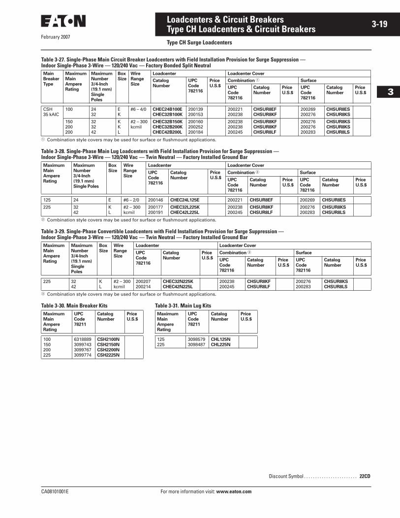
Table 3-27. Single-Phase Main Circuit Breaker Loadcenters with Field Installation Provision for Surge Suppression — Indoor Single-Phase 3-Wire — 120/240 Vac — Factory Bonded Split Neutral
� Combination style covers may be used for surface or flushmount applications.
Table 3-28. Single-Phase Main Lug Loadcenters with Field Installation Provision for Surge Suppression — Indoor Single-Phase 3-Wire — 120/240 Vac — Twin Neutral — Factory Installed Ground Bar
� Combination style covers may be used for surface or flushmount applications.
Table 3-29. Single-Phase Convertible Loadcenters with Field Installation Provision for Surge Suppression — Indoor Single-Phase 3-Wire — 120/240 Vac — Twin Neutral — Factory Installed Ground Bar
� Combination style covers may be used for surface or flushmount applications.
Table 3-30. Main Breaker Kits Table 3-31. Main Lug Kits
Main
Breaker
Type
Maximum
Main
Ampere
Rating
Maximum
Number
3/4-Inch
(19.1 mm)
Single
Poles
Box
Size
Wire
Range
Size
Loadcenter Loadcenter Cover
Catalog
Number
UPC
Code
782116
Price
U.S.$
Combination � Surface
UPC
Code
782116
Catalog
Number
Price
U.S.$
UPC
Code
782116
Catalog
Number
Price
U.S.$
CSH35 kAIC
100 2432
EK
#6 – 4/0 CHEC24B100E
CHEC32B100K
200139200153
200221200238
CHSUR8EF
CHSUR8KF
200269200276
CHSUR8ES
CHSUR8KS
150200200
323242
KKL
#2 – 300 kcmil
CHEC32B150K
CHEC32B200K
CHEC42B200L
200160200252200184
200238200238200245
CHSUR8KF
CHSUR8KF
CHSUR8LF
200276200276200283
CHSUR8KS
CHSUR8KS
CHSUR8LS
Maximum
Main
Ampere
Rating
Maximum
Number
3/4-Inch
(19.1 mm)
Single Poles
Box
Size
Wire
Range
Size
Loadcenter Loadcenter Cover
UPC
Code
782116
Catalog
Number
Price
U.S.$Combination � Surface
UPC
Code
782116
Catalog
Number
Price
U.S.$
UPC
Code
782116
Catalog
Number
Price
U.S.$
125 24 E #6 – 2/0 200146 CHEC24L125E 200221 CHSUR8EF 200269 CHSUR8ES
225 3242
KL
#2 – 300kcmil
200177200191
CHEC32L225K
CHEC42L225L
200238200245
CHSUR8KF
CHSUR8LF
200276200283
CHSUR8KS
CHSUR8LS
Maximum
Main
Ampere
Rating
Maximum
Number
3/4-Inch
(19.1 mm)
Single
Poles
Box
Size
Wire
Range
Size
Loadcenter Loadcenter Cover
UPC
Code
782116
Catalog
Number
Price
U.S.$
Combination � Surface
UPC
Code
782116
Catalog
Number
Price
U.S.$
UPC
Code
782116
Catalog
Number
Price
U.S.$
225 3242
KL
#2 – 300 kcmil
200207200214
CHEC32N225K
CHEC42N225L
200238200245
CHSUR8KF
CHSUR8LF
200276200283
CHSUR8KS
CHSUR8LS
Maximum
Main
Ampere
Rating
UPC
Code
78211
Catalog
Number
Price
U.S.$
100150200225
6318889309974330997673099774
CSH2100N
CSH2150N
CSH2200N
CSH2225N
Maximum
Main
Ampere
Rating
UPC
Code
78211
Catalog
Number
Price
U.S.$
125225
30985793098487
CHL125N
CHL225N
Discount Symbol . . . . . . . . . . . . . . . . . . . . . . . . 22CD
February 2007
3-20
For more information visit: www.eaton.com CA08101001E
Loadcenters & Circuit Breakers
3
Type CH Loadcenters & Circuit BreakersProduct Description
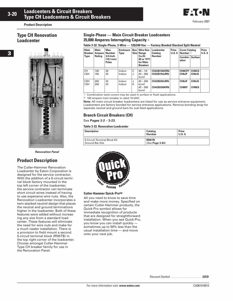
Type CH Renovation Loadcenter
Renovation Panel
Product DescriptionThe Cutler-Hammer Renovation Loadcenter by Eaton Corporation is designed for the service contractor. With the addition of a 5-circuit termi-nal block factory mounted in the top left corner of the loadcenter, the service contractor can terminate short circuit wires instead of having to use expensive wire nuts. Also, the Renovation Loadcenter incorporates a twin stacked neutral design that places the neutral and ground terminations higher in the loadcenter. Both of these features were added without increas-ing any size from a standard load-center. These features will eliminate the need for wire nuts and make for a much neater installation. There is a provision to field mount a second 5-circuit terminal block (RN5TB) in the top right corner of the loadcenter. Choose amongst Cutler-Hammer Type CH breaker family for use in the Renovation Panel.
Single-Phase — Main Circuit Breaker Loadcenters35,000 Amperes Interrupting Capacity �Table 3-32. Single-Phase, 3-Wire — 120/240 Vac — Factory Bonded Stacked Split Neutral
� Combination style covers may be used in surface or flush applications.� 100 ampere main breaker is rated 10 kAIC.Note: All main circuit breaker loadcenters are listed for use as service entrance equipment. Loadcenters are factory bonded for service entrance applications. Remove bonding strap for separate neutral and ground bars for sub-feed applications.
Branch Circuit Breakers (CH)See Pages 3-2 – 3-23.
Table 3-33. Renovation Loadcenter
Main
Breaker
Type
Main
Ampere
Rating
Max.
Number
3/4-Inch
(19.1 mm)
Poles
Enclosure
Type
Box
Size
Wire Size
Range
Cu/Al
60 or 70ºC
for Main
Breakers
Loadcenter
Catalog
Number
Price
U.S. $
Cover Catalog
Number �Price
U.S. $
Combin-
ation
Surface
CHCSH
100150
2032
IndoorIndoor
CJ
#6 – 1/0#2 – 300kcmil
CH22B100CRN
CH32B150JRN
CH8CFF
CH8JF
CH8CS
CH8JS
CSHCSH
200200
3242
IndoorIndoor
JK
#2 – 300kcmil#2 – 300kcmil
CH32B200JRN
CH42B200KRN
CH8JF
CH8KF
CH8JS
CH8KS
Description Catalog
Number
Price
U.S. $
5-Circuit Terminal Block KitGround Bar Kits
RN5TB
(See Page 3-63)
Cutler-Hammer Quick-ProSM
All you need to know to save time and make more money. Specified on certain Cutler-Hammer products, the Quick-Pro symbol allows for immediate recognition of products that are designed for straightforward installation. When you see Quick-Pro, you know you can install quickly — sometimes up to 50% less than the usual installation time — and move onto your next job.
Discount Symbol . . . . . . . . . . . . . . . . . . . . . . . . 22CD
February 2007
CA08101001E For more information visit: www.eaton.com
3-21Loadcenters & Circuit Breakers
3
Type CH Loadcenters & Circuit BreakersProduct Description
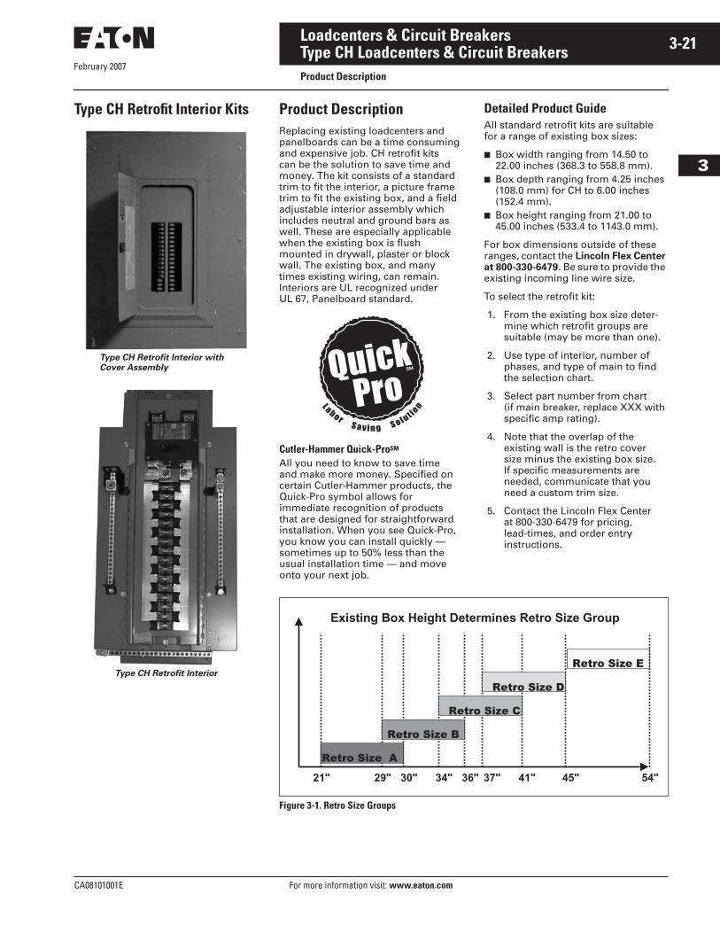
Type CH Retrofit Interior Kits
Type CH Retrofit Interior with
Cover Assembly
Type CH Retrofit Interior
Product DescriptionReplacing existing loadcenters and panelboards can be a time consuming and expensive job. CH retrofit kits can be the solution to save time and money. The kit consists of a standard trim to fit the interior, a picture frame trim to fit the existing box, and a field adjustable interior assembly which includes neutral and ground bars as well. These are especially applicable when the existing box is flush mounted in drywall, plaster or block wall. The existing box, and many times existing wiring, can remain. Interiors are UL recognized under UL 67, Panelboard standard.
Detailed Product GuideAll standard retrofit kits are suitable for a range of existing box sizes:
■ Box width ranging from 14.50 to 22.00 inches (368.3 to 558.8 mm).
■ Box depth ranging from 4.25 inches (108.0 mm) for CH to 6.00 inches (152.4 mm).
■ Box height ranging from 21.00 to 45.00 inches (533.4 to 1143.0 mm).
For box dimensions outside of these ranges, contact the Lincoln Flex Center at 800-330-6479. Be sure to provide the existing incoming line wire size.
To select the retrofit kit:
1. From the existing box size deter-mine which retrofit groups are suitable (may be more than one).
2. Use type of interior, number of phases, and type of main to find the selection chart.
3. Select part number from chart (if main breaker, replace XXX with specific amp rating).
4. Note that the overlap of the existing wall is the retro cover size minus the existing box size.If specific measurements are needed, communicate that you need a custom trim size.
5. Contact the Lincoln Flex Center at 800-330-6479 for pricing, lead-times, and order entry instructions.
Figure 3-1. Retro Size Groups
Cutler-Hammer Quick-ProSM
All you need to know to save time and make more money. Specified on certain Cutler-Hammer products, the Quick-Pro symbol allows for immediate recognition of products that are designed for straightforward installation. When you see Quick-Pro, you know you can install quickly — sometimes up to 50% less than the usual installation time — and move onto your next job.
Existing Box Height Determines Retro Size Group
21" 29" 30" 34" 36" 37" 41" 45" 54"
Retro Size A
Retro Size B
Retro Size C
Retro Size D
Retro Size E
February 2007
3-22
For more information visit: www.eaton.com CA08101001E
Loadcenters & Circuit Breakers
3
Type CH Loadcenters & Circuit BreakersProduct Selection
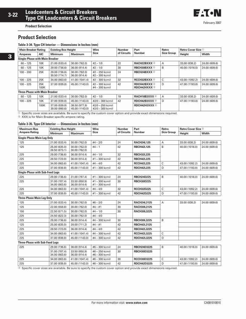
Product SelectionTable 3-34. Type CH Interior — Dimensions in Inches (mm)
� Specific cover sizes are available. Be sure to specify the custom cover option and provide exact dimensions required.� XXX is for Main Breaker specific ampere rating.
Table 3-35. Type CH Interior — Dimensions in Inches (mm)
� Specific cover sizes are available. Be sure to specify the custom cover option and provide exact dimensions required.
Main Breaker Rating Existing Box Height Wire
Size
Number
of Circuits
Part
Number
Retro
Size Group
Retro Cover Size �
Amperes AIC Minimum Maximum Height Width
Single-Phase with Main Breaker 60 – 125 10K 21.00 (533.4) 30.00 (762.0) #2 – 1/0 22 RACH22BXXX � A 33.00 (838.2) 24.00 (609.6)
60 – 125 10K 29.00 (736.6) 36.00 (914.4) #2 – 1/0 30 RBCH30BXXX � B 40.00 (1016.0) 24.00 (609.6)
100 – 200 25K 29.00 (736.6)30.50 (774.7)
30.00 (762.0)36.00 (914.4)
#2 – 250 kcmil#2 – 300 kcmil
24 RBCH24BXXX �
100 – 225 25K 34.00 (863.6) 41.00 (1041.4) #2 – 300 kcmil 32 RCCH32BXXX � C 43.00 (1092.2) 24.00 (609.6)
100 – 225 25K100K
37.00 (939.8) 45.00 (1143.0) #2 – 300 kcmil#4 – 300 kcmil
42 RDCH42BXXX �
RDCH42HXXX �D 47.00 (1193.8) 24.00 (609.6)
Three-Phase with Main Breaker 60 – 125 10K 21.00 (533.4) 30.00 (762.0) #2 – 1/0 18 RACH18B3XXX � A 33.00 (838.2) 24.00 (609.6)
100 – 225 10K 37.00 (939.8) 45.00 (1143.0) #2/0 – 300 kcmil 42 RDCH42B3XXX � D 47.00 (1193.8) 24.00 (609.6)
100K 37.00 (939.8)39.00 (990.6)
38.50 (977.9)45.00 (1143.0)
#2/0 – 250 kcmil#2/0 – 300 kcmil
RDCH42H3XXX �
Maximum Bus
Ampere Rating
Existing Box Height Wire
Size
Number
of Circuits
Part
Number
Retro
Size Group
Retro Cover Size �
Minimum Maximum Height Width
Single-Phase Main Lug Only125 21.00 (533.4) 30.00 (762.0) #4 – 2/0 24 RACH24L125 A 33.00 (838.2) 24.00 (609.6)
125 25.00 (635.0)26.50 (673.1)
30.00 (762.0)30.00 (762.0)
#4 – 1 42 RBCH42L125 B 40.00 (1016.0) 24.00 (609.6)
225 29.00 (736.6) 36.00 (914.4) #4 – 1/0 32 RBCH32L225
225 28.50 (723.9) 36.00 (914.4) #1 – 300 kcmil 42 RBCH42L225
225 34.00 (863.6) 41.00 (1041.4) #4 – 4/0 42 RCCH42L225 C 43.00 (1092.2) 24.00 (609.6)
225 37.00 (939.8) 45.00 (1143.0) #1 – 300 kcmil 42 RDCH42L225 D 47.00 (1193.8) 24.00 (609.6)
Single-Phase with Sub-Feed Lugs225 29.00 (736.6) 31.00 (787.4) #1 – 300 kcmil 24 RBCH24D225 B 40.00 (1016.0) 24.00 (609.6)
225 31.00 (787.4)34.00 (863.6)
33.50 (850.9)36.00 (914.4)
#1 – 300 kcmil #1 – 300 kcmil
30 RBCH30D225
225 34.00 (863.6) 41.00 (1041.4) #4 – 4/0 32 RCCH32D225 C 43.00 (1092.2) 24.00 (609.6)
225 37.00 (939.8) 45.00 (1143.0) #1 – 300 kcmil 42 RDCH42D225 D 47.00 (1193.8) 24.00 (609.6)
Three-Phase Main Lug Only125 21.00 (533.4) 30.00 (762.0) #6 – 2/0 24 RACH24L3125 A 33.00 (838.2) 24.00 (609.6)
125 22.00 (558.8) 30.00 (762.0) #4 – #1 30 RACH30L3125
150 22.50 (571.5) 30.00 (762.0) #4 – 1/0 30 RACH30L3225
225 24.50 (622.3) 30.00 (762.0) #4 – 4/0
225 29.00 (736.6) 36.00 (914.4) #4 – 300 kcmil 30 RBCH30L3225 B
125 25.00 (635.0) 28.00 (711.2) #4 – #1 42 RBCH42L3125
225 28.50 (723.9) 36.00 (914.4) #4 – 4/0 42 RBCH42L3225
225 34.00 (863.6) 41.00 (1041.4) #4 – 300 kcmil 42 RCCH42L3225 C
225 37.00 (939.8) 45.00 (1143.0) #4 – 300 kcmil 42 RDCH42L3225 D
Three-Phase with Sub-Feed Lugs225 29.00 (736.6) 36.00 (914.4) #6 – 300 kcmil 24 RBCH24D3225 B 40.00 (1016.0) 24.00 (609.6)
31.00 (787.4)34.00 (863.6)
33.50 (850.9)36.00 (914.4)
#6 – 250 kcmil #6 – 300 kcmil
30 RBCH30D3225
225 34.00 (863.6) 41.00 (1041.4) #6 – 300 kcmil 30 RCCH30D3225 C 43.00 (1092.2) 24.00 (609.6)
225 37.00 (939.8) 45.00 (1143.0) #6 – 300 kcmil 42 RDCH42D3225 D 47.00 (1193.8) 24.00 (609.6)
February 2007
CA08101001E For more information visit: www.eaton.com
3-23Loadcenters & Circuit Breakers
3
Type CH Loadcenters & Circuit BreakersAccessories
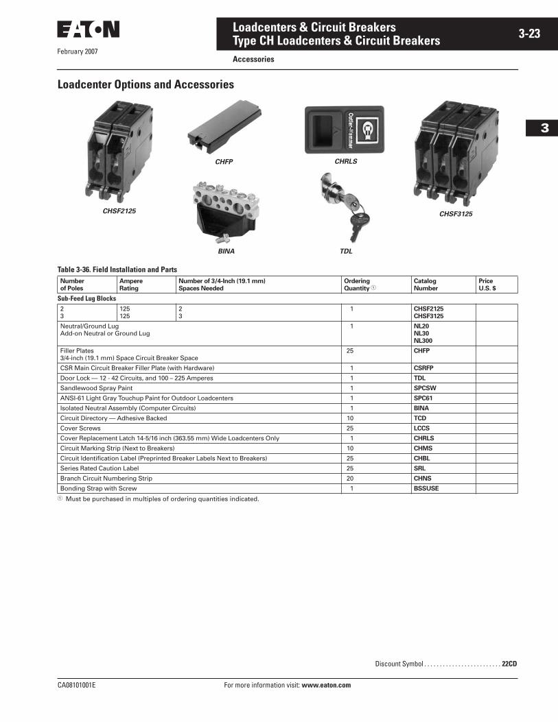
Loadcenter Options and Accessories
Table 3-36. Field Installation and Parts
� Must be purchased in multiples of ordering quantities indicated.
Number
of Poles
Ampere
Rating
Number of 3/4-Inch (19.1 mm)
Spaces Needed
Ordering
Quantity �Catalog
Number
Price
U.S. $
Sub-Feed Lug Blocks23
125125
23
1 CHSF2125
CHSF3125
Neutral/Ground LugAdd-on Neutral or Ground Lug
1 NL20
NL30
NL300
Filler Plates3/4-inch (19.1 mm) Space Circuit Breaker Space
25 CHFP
CSR Main Circuit Breaker Filler Plate (with Hardware) 1 CSRFP
Door Lock — 12 - 42 Circuits, and 100 – 225 Amperes 1 TDL
Sandlewood Spray Paint 1 SPCSW
ANSI-61 Light Gray Touchup Paint for Outdoor Loadcenters 1 SPC61
Isolated Neutral Assembly (Computer Circuits) 1 BINA
Circuit Directory — Adhesive Backed 10 TCD
Cover Screws 25 LCCS
Cover Replacement Latch 14-5/16 inch (363.55 mm) Wide Loadcenters Only 1 CHRLS
Circuit Marking Strip (Next to Breakers) 10 CHMS
Circuit Identification Label (Preprinted Breaker Labels Next to Breakers) 25 CHBL
Series Rated Caution Label 25 SRL
Branch Circuit Numbering Strip 20 CHNS
Bonding Strap with Screw 1 BSSUSE
TDL
CHRLSCHFP
CHSF2125 CHSF3125
BINA
Discount Symbol . . . . . . . . . . . . . . . . . . . . . . . . . 22CD
February 2007
3-24
For more information visit: www.eaton.com CA08101001E
Loadcenters & Circuit Breakers
3
Type CH Loadcenters & Circuit BreakersAccessories
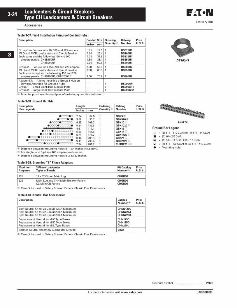
Table 3-37. Field Installation Rainproof Conduit Hubs
� Must be purchased in multiples of ordering quantities indicated.
Table 3-38. Ground Bar Kits
� Distance between mounting holes is 1-3/4 inches (44.5 mm).� For single- and 3-phase 400 ampere loadcenters.� Distance between mounting holes is 2-13/32 inches.
Table 3-39. Grounded “B” Phase Adapters
� Cannot be used in Safety Breaker Panels. Classic Plus Panels only.
Table 3-40. Neutral Bar Accessories
� Cannot be used in Safety Breaker Panels. Classic Plus Panels only.
Description Conduit Size Ordering
Quantity �Catalog
Number
Price
U.S. $Inches mm
Group 1 — For use with 70, 100 and 125 ampereMLO and MCB Loadcenters and Circuit BreakerEnclosures and the following 150 and 200
ampere panels: CH8B150RF CH8B200RF
.751.001.251.502.00
19.125.431.838.150.8
11111
DS075H1
DS100H1
DS125H1
DS150H1
DS200H1
Group 2 — For use with 150, 200 and 225 ampereMLO and MCB Loadcenters and Circuit BreakerEnclosure except for the following 150 and 200
ampere panels: CH8B150RF, CH8B200RF
2.002.50
3.00
50.863.5
76.2
11
1
DS200H2
DS250H2
DS300H2
Adapter Kit — Allows Installing a Group 1 Hub onDevices Arranged for Group 2 Hubs
Group 1 — Small Blank Hub Closure PlateGroup 2 — Large Blank Hub Closure Plate
———
———
111
DS900AP
DS900CP1
DS900CP2
Description
(See Legend)
Length Ordering
Quantity �Catalog
Number
Price
U.S. $Inches mm
���������������
�������������������������
���������������������������������
�����������������������������������������������
�����������������������
2.543.594.295.344.615.696.748.149.197.94
64.591.2
109.0135.6117.1144.5171.2206.8233.4201.7
1111111111
GBK5 �
GBK520 �
GBK10 �
GBK1020 �
GBK13 �
GBK14 �
GBK1420 �
GBK21 �
GBK2120 �
CH9GP21 ��
Maximum
Amperes
3-Phase Loadcenter
Types of Panels
Kit Catalog
Number �Price
U.S. $
125 12 – 32 Circuit Main Lug CHGRD1
225 Main Lug and CHH Main Breaker PanelsCC Main CB Panels
CHGRD2
CHGRD3
Description Catalog
Number �Price
U.S. $
Split Neutral Kit for 22 Circuit 125 A MaximumSplit Neutral Kit for 32 Circuit 200 A MaximumSplit Neutral Kit for 42 Circuit 200 A Maximum
CHSN125C
CHSN225J
CHSN225K
Replacement Neutral for all C Type BoxesReplacement Neutral for all D Type BoxesReplacement Neutral for all L Type Boxes
CHN125C
CHN125D
CHN225L
Isolated Neutral Assembly (Computer Circuits) BINA
� � � � � � � � � � � � � � �
DS100H1
GBK14
Ground Bar Legend�
�
�
= (3) #14 – #10 Cu/Al or (1) #14 – #4 Cu/Al= (1) #6 – 2/0 Cu/Al= (1) 1/0 – 14 or (3) #10 – 12 Cu/Al= (1) #14 – 1/0 Cu/Al or (3) #14 – #10 Cu/Al= Mounting Hole
Discount Symbol . . . . . . . . . . . . . . . . . . . . . . . . 22CD
� �
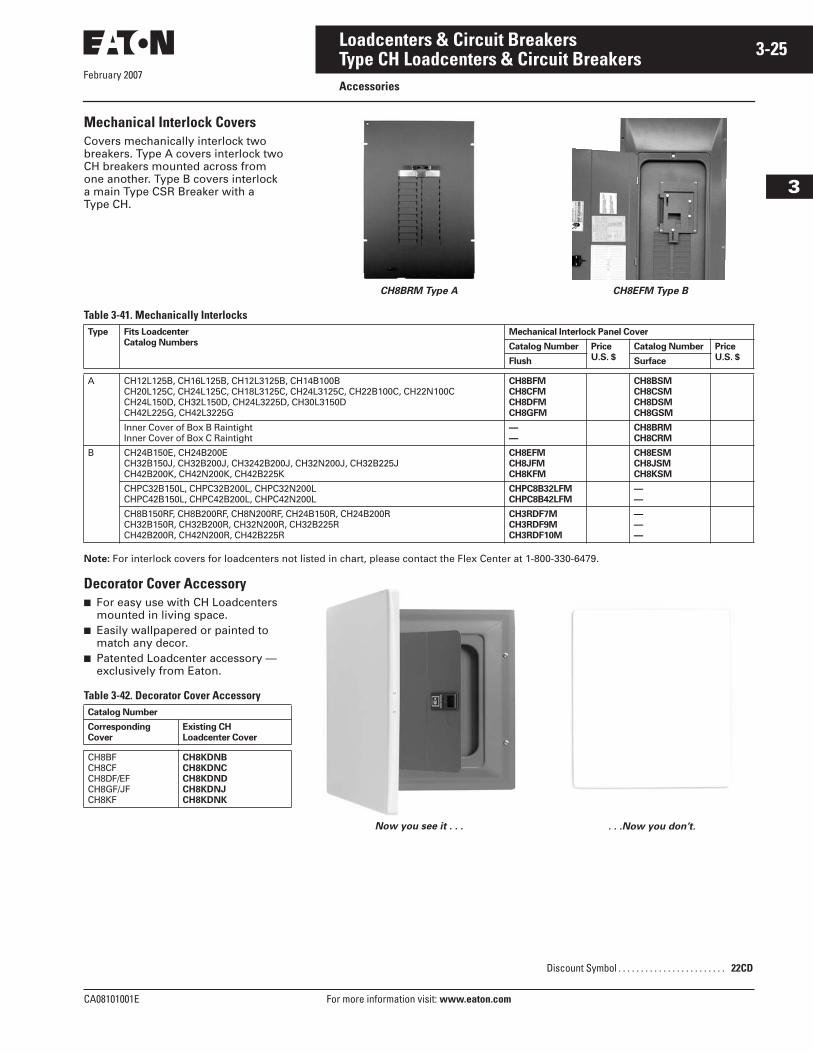
February 2007
CA08101001E For more information visit: www.eaton.com
3-25Loadcenters & Circuit Breakers
3
Type CH Loadcenters & Circuit BreakersAccessories
Mechanical Interlock CoversCovers mechanically interlock two breakers. Type A covers interlock two CH breakers mounted across from one another. Type B covers interlock a main Type CSR Breaker with a Type CH.
CH8BRM Type A CH8EFM Type B
Table 3-41. Mechanically Interlocks
Note: For interlock covers for loadcenters not listed in chart, please contact the Flex Center at 1-800-330-6479.
Decorator Cover Accessory■ For easy use with CH Loadcenters
mounted in living space.■ Easily wallpapered or painted to
match any decor.■ Patented Loadcenter accessory —
exclusively from Eaton.
Table 3-42. Decorator Cover Accessory
Now you see it . . . . . .Now you don’t.
Type Fits Loadcenter
Catalog Numbers
Mechanical Interlock Panel Cover
Catalog Number Price
U.S. $
Catalog Number Price
U.S. $Flush Surface
A CH12L125B, CH16L125B, CH12L3125B, CH14B100BCH20L125C, CH24L125C, CH18L3125C, CH24L3125C, CH22B100C, CH22N100CCH24L150D, CH32L150D, CH24L3225D, CH30L3150DCH42L225G, CH42L3225G
CH8BFM
CH8CFM
CH8DFM
CH8GFM
CH8BSM
CH8CSM
CH8DSM
CH8GSM
Inner Cover of Box B RaintightInner Cover of Box C Raintight
—
—
CH8BRM
CH8CRM
B CH24B150E, CH24B200ECH32B150J, CH32B200J, CH3242B200J, CH32N200J, CH32B225JCH42B200K, CH42N200K, CH42B225K
CH8EFM
CH8JFM
CH8KFM
CH8ESM
CH8JSM
CH8KSM
CHPC32B150L, CHPC32B200L, CHPC32N200LCHPC42B150L, CHPC42B200L, CHPC42N200L
CHPC8B32LFM
CHPC8B42LFM
—
—
CH8B150RF, CH8B200RF, CH8N200RF, CH24B150R, CH24B200RCH32B150R, CH32B200R, CH32N200R, CH32B225RCH42B200R, CH42N200R, CH42B225R
CH3RDF7M
CH3RDF9M
CH3RDF10M
—
—
—
Catalog Number
Corresponding
Cover
Existing CH
Loadcenter Cover
CH8BFCH8CFCH8DF/EFCH8GF/JFCH8KF
CH8KDNB
CH8KDNC
CH8KDND
CH8KDNJ
CH8KDNK
Discount Symbol . . . . . . . . . . . . . . . . . . . . . . . . 22CD
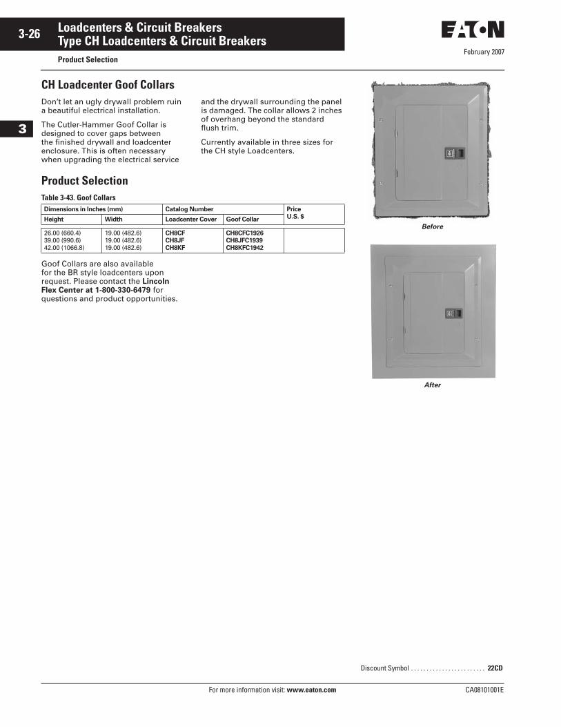
February 2007
3-26
For more information visit: www.eaton.com CA08101001E
Loadcenters & Circuit Breakers
3
Type CH Loadcenters & Circuit BreakersProduct Selection
CH Loadcenter Goof CollarsDon’t let an ugly drywall problem ruin a beautiful electrical installation.
The Cutler-Hammer Goof Collar is designed to cover gaps between the finished drywall and loadcenter enclosure. This is often necessary when upgrading the electrical service
and the drywall surrounding the panel is damaged. The collar allows 2 inches of overhang beyond the standard flush trim.
Currently available in three sizes for the CH style Loadcenters.
Product SelectionTable 3-43. Goof Collars
Goof Collars are also available for the BR style loadcenters upon request. Please contact the Lincoln Flex Center at 1-800-330-6479 for questions and product opportunities.
Dimensions in Inches (mm) Catalog Number Price
U.S. $Height Width Loadcenter Cover Goof Collar
26.00 (660.4)39.00 (990.6)42.00 (1066.8)
19.00 (482.6)19.00 (482.6)19.00 (482.6)
CH8CF
CH8JF
CH8KF
CH8CFC1926
CH8JFC1939
CH8KFC1942
Before
After
Discount Symbol . . . . . . . . . . . . . . . . . . . . . . . . 22CD
SCOTTHAS
PHOTO
SCOTTHAS
PHOTO
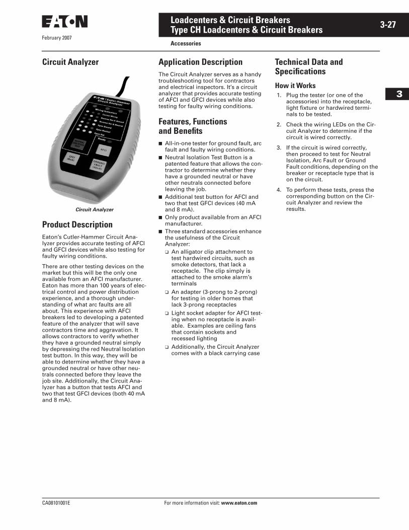
February 2007
CA08101001E For more information visit: www.eaton.com
3-27Loadcenters & Circuit Breakers
3
Type CH Loadcenters & Circuit BreakersAccessories
Circuit Analyzer
Circuit Analyzer
Product DescriptionEaton’s Cutler-Hammer Circuit Ana-lyzer provides accurate testing of AFCI and GFCI devices while also testing for faulty wiring conditions.
There are other testing devices on the market but this will be the only one available from an AFCI manufacturer. Eaton has more than 100 years of elec-trical control and power distribution experience, and a thorough under-standing of what arc faults are all about. This experience with AFCI breakers led to developing a patented feature of the analyzer that will save contractors time and aggravation. It allows contractors to verify whether they have a grounded neutral simply by depressing the red Neutral Isolation test button. In this way, they will be able to determine whether they have a grounded neutral or have other neu-trals connected before they leave the job site. Additionally, the Circuit Ana-lyzer has a button that tests AFCI and two that test GFCI devices (both 40 mA and 8 mA).
Application DescriptionThe Circuit Analyzer serves as a handy troubleshooting tool for contractors and electrical inspectors. It’s a circuit analyzer that provides accurate testing of AFCI and GFCI devices while also testing for faulty wiring conditions.
Features, Functions and Benefits■ All-in-one tester for ground fault, arc
fault and faulty wiring conditions. ■ Neutral Isolation Test Button is a
patented feature that allows the con-tractor to determine whether they have a grounded neutral or have other neutrals connected before leaving the job.
■ Additional test button for AFCI and two that test GFCI devices (40 mA and 8 mA).
■ Only product available from an AFCI manufacturer.
■ Three standard accessories enhance the usefulness of the Circuit Analyzer:❑ An alligator clip attachment to
test hardwired circuits, such as smoke detectors, that lack a receptacle. The clip simply is attached to the smoke alarm’s terminals
❑ An adapter (3-prong to 2-prong) for testing in older homes that lack 3-prong receptacles
❑ Light socket adapter for AFCI test-ing when no receptacle is avail-able. Examples are ceiling fans that contain sockets and recessed lighting
❑ Additionally, the Circuit Analyzer comes with a black carrying case
Technical Data and Specifications
How it Works1. Plug the tester (or one of the
accessories) into the receptacle, light fixture or hardwired termi-nals to be tested.
2. Check the wiring LEDs on the Cir-cuit Analyzer to determine if the circuit is wired correctly.
3. If the circuit is wired correctly, then proceed to test for Neutral Isolation, Arc Fault or Ground Fault conditions, depending on the breaker or receptacle type that is on the circuit.
4. To perform these tests, press the corresponding button on the Cir-cuit Analyzer and review the results.
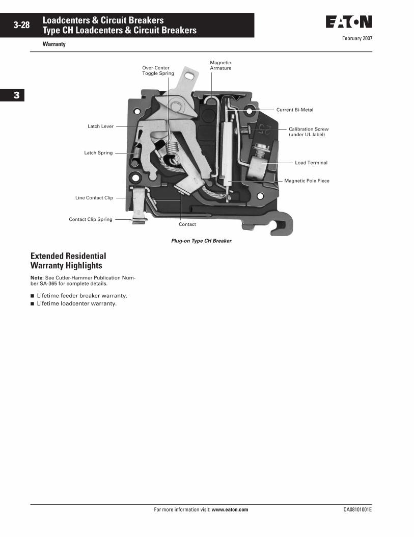
February 2007
3-28
For more information visit: www.eaton.com CA08101001E
Loadcenters & Circuit Breakers
3
Type CH Loadcenters & Circuit BreakersWarranty
Plug-on Type CH Breaker
Extended Residential Warranty HighlightsNote: See Cutler-Hammer Publication Num-ber SA-365 for complete details.
■ Lifetime feeder breaker warranty.■ Lifetime loadcenter warranty.
Latch Lever
Latch Spring
Line Contact Clip
Contact Clip SpringContact
Over-CenterToggle Spring
Magnetic Pole Piece
Load Terminal
Calibration Screw(under UL label)
Current Bi-Metal
MagneticArmature
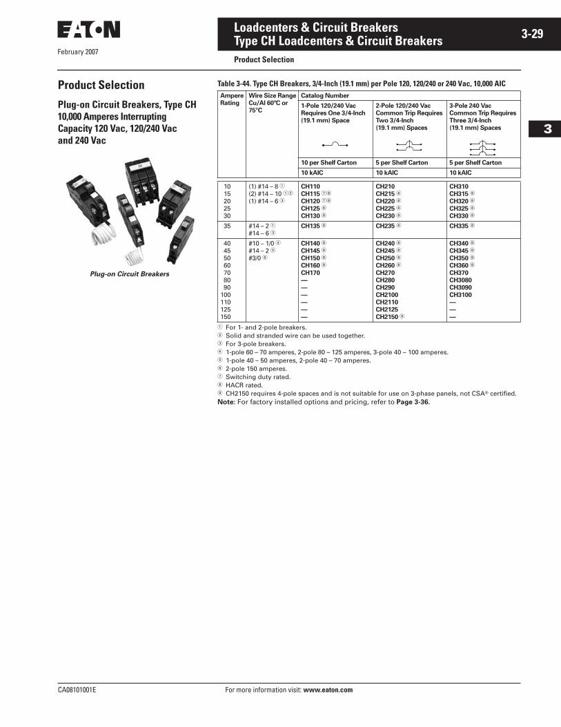
February 2007
CA08101001E For more information visit: www.eaton.com
3-29Loadcenters & Circuit Breakers
3
Type CH Loadcenters & Circuit BreakersProduct Selection
Product Selection
Plug-on Circuit Breakers, Type CH 10,000 Amperes Interrupting Capacity 120 Vac, 120/240 Vac and 240 Vac
Plug-on Circuit Breakers
Table 3-44. Type CH Breakers, 3/4-Inch (19.1 mm) per Pole 120, 120/240 or 240 Vac, 10,000 AIC
� For 1- and 2-pole breakers.� Solid and stranded wire can be used together.� For 3-pole breakers.� 1-pole 60 – 70 amperes, 2-pole 80 – 125 amperes, 3-pole 40 – 100 amperes.� 1-pole 40 – 50 amperes, 2-pole 40 – 70 amperes.� 2-pole 150 amperes.� Switching duty rated. HACR rated. CH2150 requires 4-pole spaces and is not suitable for use on 3-phase panels, not CSA� certified.Note: For factory installed options and pricing, refer to Page 3-36.
Ampere
Rating
Wire Size Range
Cu/Al 60ºC or
75°C
Catalog Number
1-Pole 120/240 Vac
Requires One 3/4-Inch
(19.1 mm) Space
2-Pole 120/240 Vac
Common Trip Requires
Two 3/4-Inch
(19.1 mm) Spaces
3-Pole 240 Vac
Common Trip Requires
Three 3/4-Inch
(19.1 mm) Spaces
10 per Shelf Carton 5 per Shelf Carton 5 per Shelf Carton
10 kAIC 10 kAIC 10 kAIC
10 15 20 25 30
(1) #14 – 8 �(2) #14 – 10 ��
(1) #14 – 6 �
CH110
CH115 �
CH120 �
CH125
CH130
CH210
CH215
CH220
CH225
CH230
CH310
CH315
CH320
CH325
CH330
35 #14 – 2 �#14 – 6 �
CH135 CH235 CH335
40 45 50 60 70 80 90100110125150
#10 – 1/0 �#14 – 2 �#3/0 �
CH140
CH145
CH150
CH160
CH170
—
—
—
—
—
—
CH240
CH245
CH250
CH260
CH270
CH280
CH290
CH2100
CH2110
CH2125
CH2150
CH340
CH345
CH350
CH360
CH370
CH3080
CH3090
CH3100
—
—
—
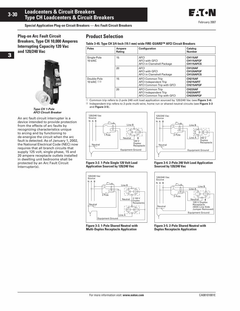
February 2007
3-30
For more information visit: www.eaton.com CA08101001E
Loadcenters & Circuit Breakers
3
Type CH Loadcenters & Circuit BreakersSpecial Application Plug-on Circuit Breakers — Arc Fault Circuit Breakers
Plug-on Arc Fault Circuit Breakers, Type CH 10,000 Amperes Interrupting Capacity 120 Vac and 120/240 Vac
Type CH 1-Pole
AFCI Circuit Breaker
An arc fault circuit interrupter is a device intended to provide protection from the effects of arc faults by recognizing characteristics unique to arcing and by functioning to de-energize the circuit when the arc fault is detected. As of January 1, 2002, the National Electrical Code (NEC) now requires that all branch circuits that supply 125 volt, single-phase, 15 and 20 ampere receptacle outlets installed in dwelling unit bedrooms shall be protected by an Arc Fault Circuit Interrupter(s).
Product SelectionTable 3-45. Type CH 3/4-Inch (19.1 mm) wide FIRE-GUARD™ AFCI Circuit Breakers
� Common trip refers to 2-pole 240 volt load application sourced by 120/240 Vac (see Figure 3-4).� Independent trip refers to 2-pole multi-wire, home run or shared neutral circuits (see Figure 3-3
and Figure 3-5).
Figure 3-2. 1-Pole Single 120 Volt Load Application Sourced by 120/240 Vac
Figure 3-3. 1-Pole Shared Neutral with Multi-Duplex Receptacle Application
Figure 3-4. 2-Pole 240 Volt Load Application Sourced by 120/240 Vac
Figure 3-5. 2-Pole Shared Neutral with Duplex Receptacle Application
Poles Ampere
Rating
Configuration Catalog
Number
Single-Pole10 kAIC
15 AFCI AFCI with GFCIAFCI in Clamshell Package
CH115AF
CH115AFGF
CH115AFCS
20 AFCI AFCI with GFCIAFCI in Clamshell Package
CH120AF
CH120AFGF
CH120AFCS
Double-Pole10 kAIC ��
15 AFCI Common TripAFCI Independent TripAFCI Common Trip with GFCI
CH215AF
CH215AFIT
CH215AFGF
20 AFCI Common TripAFCI Independent TripAFCI Common Trip with GFCI
CH220AF
CH220AFIT
CH220AFGF
N A B
120/240 VacSource
120 VDuplexReceptacle
1 Pole
Line B
Neutral
Neutral
Equipment Ground
N A B
120/240 VacSource
2-120 VDuplexReceptacles
2 Pole
Line B
Line A
Neutral
Neutral
Equipment Ground
Line B
N A B
120/240 VacSource
Line A 240 VDuplexReceptacle
2 Pole
Neutral
Equipment Ground
N A B
120/240 VacSource
Line A
120 V DuplexReceptacle(With Line SideJumper Removed)
2 Pole
Line B
Neutral
Neutral
Equipment Ground
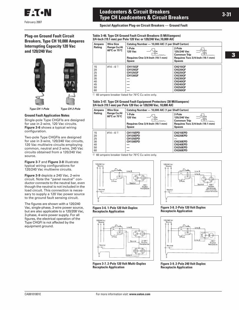
February 2007
CA08101001E For more information visit: www.eaton.com
3-31Loadcenters & Circuit Breakers
3
Type CH Loadcenters & Circuit BreakersSpecial Application Plug-on Circuit Breakers — Ground Fault
Plug-on Ground Fault Circuit Breakers, Type CH 10,000 Amperes Interrupting Capacity 120 Vac and 120/240 Vac
Ground Fault Application NotesSingle-pole Type CHGFIs are designed for use in 2-wire, 120 Vac circuits. Figure 3-6 shows a typical wiring configuration.
Two-pole Type CHGFIs are designed for use in 3-wire, 120/240 Vac circuits, 120 Vac multiwire circuits employing common, neutral and 2-wire, 240 Vac circuits obtained from a 120/240 Vac source.
Figure 3-7 and Figure 3-8 illustrate typical wiring configurations for120/240 Vac multiwire circuits.
Figure 3-9 depicts a 240 Vac, 2-wire circuit. Note the “panel neutral” con-ductor connects to the neutral bar, even though the neutral is not included in the load circuit. This connection is neces-sary to supply a 120 Vac power source to the ground fault sensing circuit.
The figures are shown with a 120/240 Vac, single-phase, 3-wire power source, but are also applicable to a 120/208 Vac, 3-phase, 4-wire power supply. For all figures, the electrical operation of the Type CHGFI is not affected by the equipment ground.
Type CH 1-Pole Type CH 2-Pole
Table 3-46. Type CH Ground Fault Circuit Breakers (5 Milliampere)3/4-Inch (19.1 mm) per Pole 120 Vac or 120/240 Vac,10,000 AIC
� 60 ampere breaker listed for 75°C Cu wire only.
Table 3-47. Type CH Ground Fault Equipment Protectors (30 Milliampere)3/4-Inch (19.1 mm) per Pole 120 Vac or 120/240 Vac, 10,000 AIC
� 60 ampere breaker listed for 75°C Cu wire only.
Figure 3-6. 1-Pole 120 Volt Duplex Receptacle Application
Figure 3-7. 2-Pole 120 Volt Multi-Duplex Receptacle Application
Figure 3-8. 2-Pole 120 Volt Duplex Receptacle Application
Figure 3-9. 2-Pole 240 Volt Duplex Receptacle Application
Ampere
Rating
Wire Size
Range Cu/Al
60ºC or 75°C
Catalog Number — 10,000 AIC (1 per Shelf Carton)
1-Pole
120 Vac
Requires One 3/4-Inch (19.1 mm)
Space
2-Pole
120/240 Vac
Common Trip
Requires Two 3/4-Inch (19.1 mm)
Spaces
152025303540455060
#14 – 6 � CH115GFCH120GFCH125GFCH130GF—————
CH215GFCH220GFCH225GFCH230GFCH235GFCH240GFCH245GFCH250GFCH260GF
Ampere
Rating
Wire Size
Range Cu/Al
60ºC or 75°C
Catalog Number — 10,000 AIC (1 per Shelf Carton)
1-Pole
120 Vac
Requires One 3/4-Inch (19.1 mm)
Space
2-Pole
120/240 Vac
Common Trip
Requires Two 3/4-Inch (19.1 mm)
Spaces
15202530405060
#14 – 6 � CH115EPDCH120EPDCH125EPDCH130EPD———
CH215EPDCH220EPD—CH230EPDCH240EPDCH250EPDCH260EPD
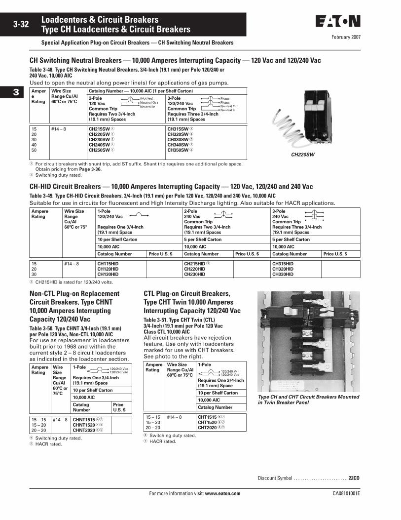
February 2007
3-32
For more information visit: www.eaton.com CA08101001E
Loadcenters & Circuit Breakers
3
Type CH Loadcenters & Circuit BreakersSpecial Application Plug-on Circuit Breakers — CH Switching Neutral Breakers
CH Switching Neutral Breakers — 10,000 Amperes Interrupting Capacity — 120 Vac and 120/240 VacTable 3-48. Type CH Switching Neutral Breakers, 3/4-Inch (19.1 mm) per Pole 120/240 or 240 Vac, 10,000 AICUsed to open the neutral along power line(s) for applications of gas pumps.
� For circuit breakers with shunt trip, add ST suffix. Shunt trip requires one additional pole space. Obtain pricing from Page 3-36.
� Switching duty rated.
CH-HID Circuit Breakers — 10,000 Amperes Interrupting Capacity — 120 Vac, 120/240 and 240 VacTable 3-49. Type CH-HID Circuit Breakers, 3/4-Inch (19.1 mm) per Pole 120 Vac, 120/240 and 240 Vac, 10,000 AICSuitable for use in circuits for fluorescent and High Intensity Discharge lighting. Also suitable for HACR applications.
� CH215HID is rated for 120/240 volts.
Non-CTL Plug-on ReplacementCircuit Breakers, Type CHNT 10,000 Amperes InterruptingCapacity 120/240 VacTable 3-50. Type CHNT 3/4-Inch (19.1 mm) per Pole 120 Vac, Non-CTL 10,000 AICFor use as replacement in loadcenters built prior to 1968 and within the current style 2 – 8 circuit loadcenters as indicated in the loadcenter section.
� Switching duty rated.� HACR rated.
CTL Plug-on Circuit Breakers, Type CHT Twin 10,000 Amperes Interrupting Capacity 120/240 VacTable 3-51. Type CHT Twin (CTL) 3/4-Inch (19.1 mm) per Pole 120 Vac Class CTL 10,000 AICAll circuit breakers have rejection feature. Use only with loadcenters marked for use with CHT breakers. See photo to the right.
� Switching duty rated.� HACR rated.
Type CH and CHT Circuit Breakers Mounted
in Twin Breaker Panel
Amper
e
Rating
Wire Size
Range Cu/Al
60ºC or 75°C
Catalog Number — 10,000 AIC (1 per Shelf Carton)
2-Pole
120 Vac
Common Trip
Requires Two 3/4-Inch
(19.1 mm) Spaces
3-Pole
120/240 Vac
Common Trip
Requires Three 3/4-Inch
(19.1 mm) Spaces
1520304050
#14 – 8 CH215SW �
CH220SW �
CH230SW �
CH240SW �
CH250SW �
CH315SW �
CH320SW �
CH330SW �
CH340SW �
CH350SW �
Ampere
Rating
Wire Size
Range
Cu/Al
60ºC or 75°
1-Pole
120/240 Vac
Requires One 3/4-Inch
(19.1 mm) Space
2-Pole
240 Vac
Common Trip
Requires Two 3/4-Inch
(19.1 mm) Spaces
3-Pole
240 Vac
Common Trip
Requires Three 3/4-Inch
(19.1 mm) Spaces
10 per Shelf Carton 5 per Shelf Carton 5 per Shelf Carton
10,000 AIC 10,000 AIC 10,000 AIC
Catalog Number Price U.S. $ Catalog Number Price U.S. $ Catalog Number Price U.S. $
152030
#14 – 8 CH115HID
CH120HID
CH130HID
CH215HID �
CH220HID
CH230HID
CH315HID
CH320HID
CH330HID
CH220SW
Neutral InNeutral Out(Hot leg)
Neutral InNeutral OutPhasePhase
Ampere
Rating
Wire
Size
Range
Cu/Al
60ºC or
75°C
1-Pole
Requires One 3/4-Inch
(19.1 mm) Space
10 per Shelf Carton
10,000 AIC
Catalog
Number
Price
U.S. $
15 – 1515 – 2020 – 20
#14 – 8 CHNT1515 ��
CHNT1520 ��
CHNT2020 ��
120/240 Vac120/240 Vac
Ampere
Rating
Wire Size
Range Cu/Al
60ºC or 75°C
1-Pole
Requires One 3/4-Inch
(19.1 mm) Space
10 per Shelf Carton
10,000 AIC
Catalog Number
15 – 1515 – 2020 – 20
#14 – 8 CHT1515 ��
CHT1520 ��
CHT2020 ��
120/240 Vac120/240 Vac
Discount Symbol . . . . . . . . . . . . . . . . . . . . . . . . 22CD
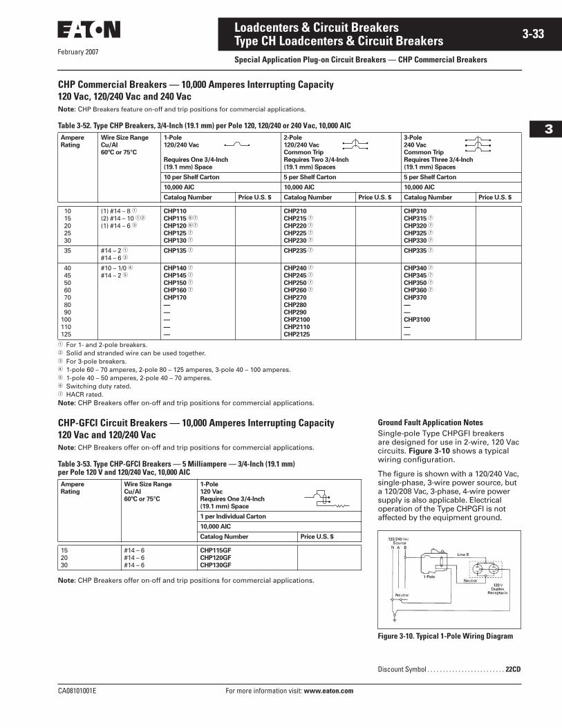
CA08101001E For more information visit: www.eaton.com
3-33Loadcenters & Circuit Breakers
February 2007
3
Type CH Loadcenters & Circuit BreakersSpecial Application Plug-on Circuit Breakers — CHP Commercial Breakers
CHP Commercial Breakers — 10,000 Amperes Interrupting Capacity120 Vac, 120/240 Vac and 240 VacNote: CHP Breakers feature on-off and trip positions for commercial applications.
Table 3-52. Type CHP Breakers, 3/4-Inch (19.1 mm) per Pole 120, 120/240 or 240 Vac, 10,000 AIC
� For 1- and 2-pole breakers.� Solid and stranded wire can be used together.� For 3-pole breakers.� 1-pole 60 – 70 amperes, 2-pole 80 – 125 amperes, 3-pole 40 – 100 amperes.� 1-pole 40 – 50 amperes, 2-pole 40 – 70 amperes.� Switching duty rated.� HACR rated.Note: CHP Breakers offer on-off and trip positions for commercial applications.
CHP-GFCI Circuit Breakers — 10,000 Amperes Interrupting Capacity 120 Vac and 120/240 VacNote: CHP Breakers offer on-off and trip positions for commercial applications.
Table 3-53. Type CHP-GFCI Breakers — 5 Milliampere — 3/4-Inch (19.1 mm) per Pole 120 V and 120/240 Vac, 10,000 AIC
Note: CHP Breakers offer on-off and trip positions for commercial applications.
Ampere
Rating
Wire Size Range
Cu/Al
60ºC or 75°C
1-Pole
120/240 Vac
Requires One 3/4-Inch
(19.1 mm) Space
2-Pole
120/240 Vac
Common Trip
Requires Two 3/4-Inch
(19.1 mm) Spaces
3-Pole
240 Vac
Common Trip
Requires Three 3/4-Inch
(19.1 mm) Spaces
10 per Shelf Carton 5 per Shelf Carton 5 per Shelf Carton
10,000 AIC 10,000 AIC 10,000 AIC
Catalog Number Price U.S. $ Catalog Number Price U.S. $ Catalog Number Price U.S. $
10 15 20 25 30
(1) #14 – 8 �
(2) #14 – 10 ��
(1) #14 – 6 �
CHP110
CHP115 ��
CHP120 ��
CHP125 �
CHP130 �
CHP210
CHP215 �
CHP220 �
CHP225 �
CHP230 �
CHP310
CHP315 �
CHP320 �
CHP325 �
CHP330 �
35 #14 – 2 �
#14 – 6 �CHP135 � CHP235 � CHP335 �
40 45 50 60 70 80 90100110125
#10 – 1/0 �
#14 – 2 �CHP140 �
CHP145 �
CHP150 �
CHP160 �
CHP170
—
—
—
—
—
CHP240 �
CHP245 �
CHP250 �
CHP260 �
CHP270
CHP280
CHP290
CHP2100
CHP2110
CHP2125
CHP340 �
CHP345 �
CHP350 �
CHP360 �
CHP370
—
—
CHP3100
—
—
Ampere
Rating
Wire Size Range
Cu/Al
60ºC or 75°C
1-Pole
120 Vac
Requires One 3/4-Inch
(19.1 mm) Space
1 per Individual Carton
10,000 AIC
Catalog Number Price U.S. $
152030
#14 – 6#14 – 6#14 – 6
CHP115GF
CHP120GF
CHP130GF
Ground Fault Application NotesSingle-pole Type CHPGFI breakers are designed for use in 2-wire, 120 Vac circuits. Figure 3-10 shows a typical wiring configuration.
The figure is shown with a 120/240 Vac, single-phase, 3-wire power source, but a 120/208 Vac, 3-phase, 4-wire power supply is also applicable. Electrical operation of the Type CHPGFI is not affected by the equipment ground.
Figure 3-10. Typical 1-Pole Wiring Diagram
Discount Symbol . . . . . . . . . . . . . . . . . . . . . . . . . 22CD
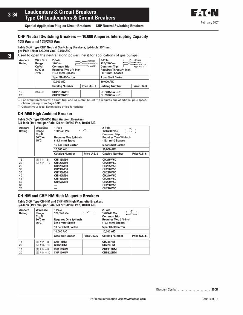
February 2007
3-34
For more information visit: www.eaton.com CA08101001E
Loadcenters & Circuit Breakers
3
Type CH Loadcenters & Circuit BreakersSpecial Application Plug-on Circuit Breakers — CHP Neutral Switching Breakers
CHP Neutral Switching Breakers — 10,000 Amperes Interrupting Capacity 120 Vac and 120/240 VacTable 3-54. Type CHP Neutral Switching Breakers, 3/4-Inch (19.1 mm) per Pole 120 or 120/240 Vac, 10,000 AICUsed to open the neutral along power line(s) for applications of gas pumps.
� For circuit breakers with shunt trip, add ST suffix. Shunt trip requires one additional pole space, obtain pricing from Page 3-36.
� Contact your local Eaton sales office for pricing.
CH-M50 High Ambient BreakerTable 3-55. Type CH-M50 High Ambient Breakers 3/4-Inch (19.1 mm) per Pole 120 or 120/240 Vac, 10,000 AIC
CH-HM and CHP-HM High Magnetic BreakersTable 3-56. Type CH-HM and CHP-HM High Magnetic Breakers 3/4-Inch (19.1 mm) per Pole 120 or 120/240 Vac, 10,000 AIC
Ampere
Rating
Wire Size
Range
Cu/Al
60ºC or
75°C
2-Pole
120 Vac
Common Trip
Requires Two 3/4-Inch
(19.1 mm) Spaces
3-Pole
120/240 Vac
Common Trip
Requires Three 3/4-Inch
(19.1 mm) Spaces
1 per Shelf Carton 1 per Shelf Carton
10,000 AIC 10,000 AIC
Catalog Number Price U.S. $ Catalog Number Price U.S. $
1520
#14 – 8 CHP215SW �
CHP220SW �CHP315SW ��
CHP320SW ��
Ampere
Rating
Wire Size
Range
Cu/Al
60ºC or
75°C
1-Pole
120/240 Vac
Requires One 3/4-Inch
(19.1 mm) Space
2-Pole
120/240 Vac
Common Trip
Requires Two 3/4-Inch
(19.1 mm) Spaces
10 per Shelf Carton 5 per Shelf Carton
10,000 AIC 10,000 AIC
Catalog Number Price U.S. $ Catalog Number Price U.S. $
15202530354045506070
(1) #14 – 8(2) #14 – 10
CH115M50
CH120M50
CH125M50
CH130M50
CH135M50
CH140M50
CH145M50
CH150M50
—
—
CH215M50
CH220M50
CH225M50
CH230M50
CH235M50
CH240M50
CH245M50
CH250M50
CH260M50
CH270M50
Ampere
Rating
Wire Size
Range
Cu/Al
60ºC or
75°C
1-Pole
120/240 Vac
Requires One 3/4-Inch
(19.1 mm) Space
2-Pole
120/240 Vac
Common Trip
Requires Two 3/4-Inch
(19.1 mm) Spaces
10 per Shelf Carton 5 per Shelf Carton
10,000 AIC 10,000 AIC
Catalog Number Price U.S. $ Catalog Number Price U.S. $
1520
(1) #14 – 8(2) #14 – 10
CH115HM
CH120HM
CH215HM
CH220HM
1520
(1) #14 – 8(2) #14 – 10
CHP115HM
CHP120HM
CHP215HM
CHP220HM
Neutral InNeutral Out(Hot leg)
Neutral InNeutral OutPhasePhase
Discount Symbol . . . . . . . . . . . . . . . . . . . . . . . . 22CD
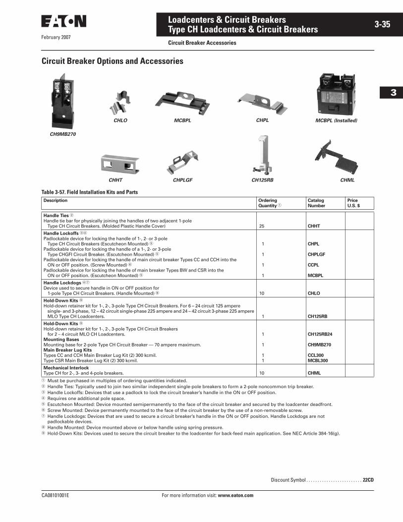
February 2007
CA08101001E For more information visit: www.eaton.com
3-35Loadcenters & Circuit Breakers
3
Type CH Loadcenters & Circuit BreakersCircuit Breaker Accessories
Circuit Breaker Options and Accessories
Table 3-57. Field Installation Kits and Parts
� Must be purchased in multiples of ordering quantities indicated.� Handle Ties: Typically used to join two similar independent single-pole breakers to form a 2-pole noncommon trip breaker.� Handle Lockoffs: Devices that use a padlock to lock the circuit breaker’s handle in the ON or OFF position.� Requires one additional pole space.� Escutcheon Mounted: Device mounted semipermanently to the face of the circuit breaker and secured by the loadcenter deadfront.� Screw Mounted: Device permanently mounted to the face of the circuit breaker by the use of a non-removable screw.� Handle Lockdogs: Devices that are used to secure a circuit breaker’s handle in the ON or OFF position. Handle Lockdogs are not
padlockable devices. Handle Mounted: Device mounted above or below handle using spring pressure. Hold-Down Kits: Devices used to secure the circuit breaker to the loadcenter for back-feed main application. See NEC Article 384-16(g).
Description Ordering
Quantity �Catalog
Number
Price
U.S. $
Handle Ties �Handle tie bar for physically joining the handles of two adjacent 1-pole
Type CH Circuit Breakers. (Molded Plastic Handle Cover) 25 CHHT
Handle Lockoffs ��
Padlockable device for locking the handle of 1-, 2- or 3-pole Type CH Circuit Breakers (Escutcheon Mounted) �
Padlockable device for locking the handle of a 1-, 2- or 3-pole Type CHGFI Circuit Breaker. (Escutcheon Mounted) �
Padlockable device for locking the handle of main circuit breaker Types CC and CCH into the ON or OFF position. (Screw Mounted) �
Padlockable device for locking the handle of main breaker Types BW and CSR into the ON or OFF position. (Escutcheon Mounted) �
1
1
1
1
CHPL
CHPLGF
CCPL
MCBPL
Handle Lockdogs ��
Device used to secure handle in ON or OFF position for 1-pole Type CH Circuit Breakers. (Handle Mounted) 10 CHLO
Hold-Down Kits
Hold-down retainer kit for 1-, 2-, 3-pole Type CH Circuit Breakers. For 6 – 24 circuit 125 ampere single- and 3-phase, 12 – 42 circuit single-phase 225 ampere and 24 – 42 circuit 3-phase 225 ampere MLO Type CH Loadcenters. 1 CH125RB
Hold-Down Kits
Hold-down retainer kit for 1-, 2-, 3-pole Type CH Circuit Breakers for 2 – 4 circuit MLO CH Loadcenters.
Mounting Bases
Mounting base for 2-pole Type CH Circuit Breaker — 70 ampere maximum.Main Breaker Lug Kits
Types CC and CCH Main Breaker Lug Kit (2) 300 kcmil.Type CSR Main Breaker Lug Kit (2) 300 kcmil.
1
1
11
CH125RB24
CH9MB270
CCL300
MCBL300
Mechanical Interlock
Type CH for 2-, 3- and 4-pole breakers. 10 CHML
CHML
CH9MB270
CHLO MCBPL CHPL MCBPL (Installed)
CHHT CHPLGF CH125RB
Discount Symbol . . . . . . . . . . . . . . . . . . . . . . . . . 22CD
February 2007
3-36
For more information visit: www.eaton.com CA08101001E
Loadcenters & Circuit Breakers
3
Type CH Loadcenters & Circuit BreakersCircuit Breaker Accessories
Table 3-58. Shunt Trip Options
� Add suffix indicated to end of breaker catalog number.� Requires one additional pole space.
Table 3-59. Handle Position Changeability ChartDescription Catalog Number
Suffix Adder �Price U.S. $
Adder EachType Volts
CSRCSRCSR
12 dc24 dc
120 ac
SR12
SR24
SR01
CHCCCC
120 ac12 dc24 dc
ST �
SR12
SR24
CCCCCC
120 ac208 ac240 ac
SR01
SR08
SR02
Handle Lockoff and
Lockdog Types
To Change Handle Position
from “On to “Off”
or “Off” to “On” You Must...
Remove
Padlock
Remove
Device
Remove
Loadcenter
Deadfront
Lockoff Escutcheon MountedLockoff Screw MountedLockdog Handle Mounted
RemoveRemoveN/A
——Remove
———
Discount Symbol . . . . . . . . . . . . . . . . . . . . . . . . 22CD
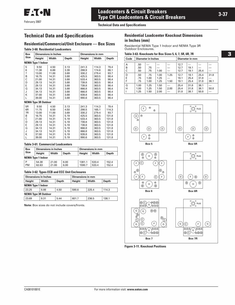
February 2007
CA08101001E For more information visit: www.eaton.com
3-37Loadcenters & Circuit Breakers
3
Type CH Loadcenters & Circuit BreakersTechnical Data and Specifications
Technical Data and Specifications
Residential/Commercial/Unit Enclosure — Box SizesTable 3-60. Residential Loadcenters
Table 3-61. Commercial Loadcenters
Table 3-62. Types ECB and ECC Unit Enclosures
Note: Box sizes do not include covers/fronts.
Residential Loadcenter Knockout Dimensions in Inches (mm)Residential NEMA Type 1 Indoor and NEMA Type 3R Outdoor Enclosures.
Table 3-63. Knockouts for Box Sizes 5, 6, 7, 5R, 6R, 7R
Figure 3-11. Knockout Positions
Box
Size
Dimensions in Inches Dimensions in mm
Height Width Depth Height Width Depth
NEMA Type 1 Indoor567BCDEGJKL
9.5011.3813.0016.7521.0029.1329.1334.1334.1337.0039.00
4.50 6.8811.0014.3114.3114.3114.3114.3114.3114.3114.31
3.133.393.693.883.883.883.883.883.883.883.88
241.3288.9330.2425.5533.4739.8739.8866.8866.8939.8990.6
114.3174.6279.4363.5363.5363.5363.5363.5363.5363.5363.5
79.4 86.1 93.7 98.4 98.4 98.4 98.4 98.4 98.4 98.4 98.4
NEMA Type 3R Outdoor5R6R7RBCDEGJKL
9.5011.7513.0016.7521.0029.1329.1334.1334.1337.0039.00
4.50 6.5011.0014.3114.3114.3114.3114.3114.3114.3114.31
3.134.503.695.195.195.195.195.195.195.195.19
241.3298.5330.2425.5533.4739.8739.8866.8866.8939.8990.6
114.3165.1279.4363.5363.5363.5363.5363.5363.5363.5363.5
79.4114.3 93.7131.8131.8131.8131.8131.8131.8131.8131.8
Box
Size
Dimensions in Inches Dimensions in mm
Height Width Depth Height Width Depth
NEMA Type 1 IndoorPPM
54.3862.63
21.0021.00
6.006.00
1381.11590.7
533.4533.4
152.4152.4
Dimensions in Inches Dimensions in mm
Height Width Depth Height Width Depth
NEMA Type 1 Indoor23.25 8.88 4.50 590.6 225.4 114.3
NEMA Type 3R Outdoor23.69 9.31 5.44 601.7 236.5 138.1
Code Diameter in Inches Diameter in mm
ABC
.50 .50 .50
— .75 .75
——1.00
———
12.712.712.7
—19.119.1
——25.4
———
DEF
.50 .75 .75
.751.001.00
1.001.251.25
1.25—1.50
12.719.119.1
19.125.425.4
25.431.831.8
31.8—38.1
GHI
1.001.001.25
1.251.251.50
1.501.502.00
—2.00—
25.425.431.8
31.831.838.1
38.138.150.8
—50.8—
Box 6R
Box 7 Box 7R
Box 5 Box 5R
Box 6
A
A
D D D
F
Hub
A
A
BA
B
B
C
C
F F
FF
AB
F
F
H
A
B
A
BH
F
B B
B
H
Hub
D D
A
A
AA
A
AAA
AAA AAA
B B B
A B B
B
BB
B
C CC
C
C
B C
G
G
GG
G GF
AAA AAA
A B BB C
C
G
G GF
Hub
A
A
A
A
A
A
D D D
D
F
F
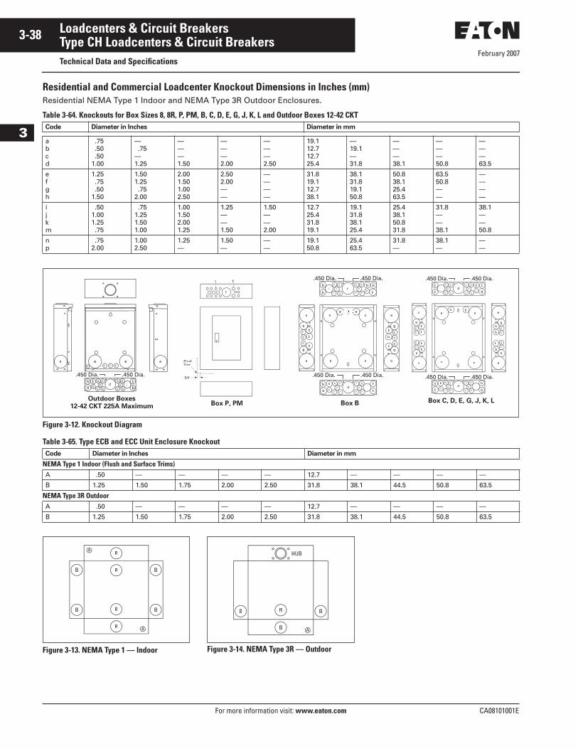
February 2007
3-38
For more information visit: www.eaton.com CA08101001E
Loadcenters & Circuit Breakers
3
Type CH Loadcenters & Circuit BreakersTechnical Data and Specifications
Residential and Commercial Loadcenter Knockout Dimensions in Inches (mm)Residential NEMA Type 1 Indoor and NEMA Type 3R Outdoor Enclosures.
Table 3-64. Knockouts for Box Sizes 8, 8R, P, PM, B, C, D, E, G, J, K, L and Outdoor Boxes 12-42 CKT
Figure 3-12. Knockout Diagram
Table 3-65. Type ECB and ECC Unit Enclosure Knockout
Figure 3-13. NEMA Type 1 — Indoor Figure 3-14. NEMA Type 3R — Outdoor
Code Diameter in Inches Diameter in mm
abcd
.75 .50 .501.00
— .75—1.25
———1.50
———2.00
———2.50
19.112.712.725.4
—19.1—31.8
———38.1
———50.8
———63.5
efgh
1.25 .75 .501.50
1.501.25 .752.00
2.001.501.002.50
2.502.00——
————
31.819.112.738.1
38.131.819.150.8
50.838.125.463.5
63.550.8——
————
ijkm
.501.001.25 .75
.751.251.501.00
1.001.502.001.25
1.25——1.50
1.50——2.00
12.725.431.819.1
19.131.838.125.4
25.438.150.831.8
31.8——38.1
38.1——50.8
np
.752.00
1.002.50
1.25—
1.50—
——
19.150.8
25.463.5
31.8—
38.1—
——
Code Diameter in Inches Diameter in mm
NEMA Type 1 Indoor (Flush and Surface Trims)A .50 — — — — 12.7 — — — —
B 1.25 1.50 1.75 2.00 2.50 31.8 38.1 44.5 50.8 63.5
NEMA Type 3R OutdoorA .50 — — — — 12.7 — — — —
B 1.25 1.50 1.75 2.00 2.50 31.8 38.1 44.5 50.8 63.5
e e e e
db
bi
bg
bc
c c ca
.450 Dia..450 Dia.
FlushTrim
3/4
c
h
b
b
e
g
b
b
cc
c
g
e
b
e
g
b
b
cc
c
g
e
e e
ee
g g
dc c
ccc
b
bi
cc
cc
b
g
bc
dcc
cc c
b
bi
ccc
c c
b
g
b
c
.450 Dia..450 Dia.
.450 Dia..450 Dia.
b
e
g
b
b
cc
g
e
e e
ee
g g
b
cc
b
e
g
b
b
cc
c
g
e
bc
dc c
ccc
b
bi
cc
cc
b
g
bc
dcc
cc c
b
bi
ccc
c c
b
g
b
c
.450 Dia..450 Dia.
.450 Dia..450 Dia.
Box P, PMOutdoor Boxes
12-42 CKT 225A MaximumBox B Box C, D, E, G, J, K, L
B
B
B
B
AA
AA
B
B
B
B B
B AA
B B
HUB

February 2007
CA08101001E For more information visit: www.eaton.com
3-39Loadcenters & Circuit Breakers
3
Type BR Loadcenters & Circuit BreakersProduct Description
Product DescriptionLoadcenters are enclosures specifically designed to house the branch circuit breakers and wiring required to distribute power to individual circuits. They contain either a main breaker when used at the service entrance point or a main lug when used as a sub-panel to add circuits to existing service. The main breaker protects the main entire panel and can be used as a service disconnect. The branch breakers protect the wires leading to individual electrical loads such as fixtures and outlets.
Single-Phase
Main Circuit Breaker
Riser Panel
Single-Phase Main Lugs
Three-Phase
Main Circuit Breaker
Main Circuit Breaker Commercial
3-Phase Main Lugs
Convertible
Convertible — Outdoor
Outdoor Circuit Breaker Unit Enclosures
ECB Breaker Enclosure
February 2007
3-40
For more information visit: www.eaton.com CA08101001E
Loadcenters & Circuit Breakers
3
Type BR Loadcenters & Circuit BreakersApplication Description/Standards Certification
Application DescriptionLoadcenter ConstructionCutler-Hammer Type BR loadcenters by Eaton Corporation have standard tin-plated aluminum bus with a limited availability of copper bus. The sum of the handle ratings connected to any stab is limited to 150 amperes maximum on the 100 and 125 ampere loadcenters, and 200 amperes on loadcenters with 150 ampere or higher main bus. NEMA Type 1 boxes or enclosures are manu-factured from galvanized steel. Raintight boxes are manufactured from galva-nized steel, then finished using an elec-trostatic powder coat, baked urethane paint process.
NeutralsEaton’s Cutler-Hammer Type BR load-centers have three types of neutrals:
Factory Bonded Split Neutral Certain single-phase main circuit breaker panels are supplied with a factory-bonded twin neutral. When used as a sub panel, the bonding strap should be removed, and the bonding screw should be reinstalled. The bonded side is now the ground, and the un-bonded side is the neutral. When used as a service entrance panel, the unused neutral holes on either side may be used for terminat-ing ground wires.
Insulated Split NeutralMost single-phase panels (12 circuits and greater) are supplied with a twin neutral with an insulated cross strap. These panels are shipped in an un-bonded state. For service entrance applications, the neutral must be bonded utilizing the bonding strap supplied with the panel. For sub-feed applications, the panel may be installed as is. Separate ground bars are provided on these panels.
Single NeutralSingle-phase 2 – 8 circuit, three-phase and commercial loadcenters are supplied with a single insulated/bondable neutral. The three-phase loadcenter neutral is movable to the other side if desired. The neutral is bondable in the field by means of a bonding strap that is supplied with each loadcenter. For sub-feed applica-tions, a separate ground bar must be used. In a service entrance application, where the neutral is bonded, unused neutral connections may be used for equipment ground protectors.
GroundsIn service entrance applications where the neutral is bonded, unused neutral holes may be used for terminating ground conductors. In sub-feed pan-els, the neutral must be isolated (non-bonded), and ground wires must be terminated on a separate ground bar.
The Factory Bonded Split Neutral panels have sufficient terminations for both ground and neutral conductors. The Insulated Split Neutral panels are supplied with a separate factory-installed ground bar if the catalog number con-tains a “G.” If not, a separate ground bar should be installed. Insulated/Bondable Single Neutral panels are supplied with-out a ground bar (unless otherwise noted), and ground bar kits if needed must be purchased separately.
Neutral and Ground TerminalsThe standard terminals on grounds and neutrals are rated to accept (3) — #14 – #10 Cu/Al or (1) — #14 – 4. For larger cables, add-on neutral lugs may be ordered from the accessories on Page 3-63.
Note: NEC allows only one current carrying conductor per hole on neutrals unless otherwise noted.
Bottom Fed LoadcentersWhere power cable is brought into the loadcenter from below the panel, main lug panels, and single-phase, 225 ampere and below loadcenters can be rotated 180 degrees to allow straight-in wiring of power cables to the main terminals. Because the main circuit breaker handle operates horizontally, the orientation of the main circuit breaker handle is consistent with the requirements of NEC Article 240-81.
Gutter SplicingLoadcenters are not UL listed as wiring troughs. Therefore, gutter splicing of riser cables to tap off to the main device is not permitted. Refer to NEC Article 373-8.
Fire RatingDue to the numerous openings in both loadcenter boxes and trims, they should not be mounted in firewalls. There is no approved method for seal-ing the enclosures for this application.
Date CodeThe date of manufacture of each load-center is printed on the outside of the carton as well as inside the loadcenter. On the carton, the date code is printed on the end carton label. In the load-center, the date code is located on the small white label located on the right side wall (with the main device on top).
The date code is in the following for-mat: F # # # &. The “F” is the numeric code for the Lincoln, IL plant, and the three numbers are the year and week of manufacture e.g., 023. The “&” sign at the end signifies the decade of the 2000s. Therefore, the date code F023& would indicate that the product was manufactured in the 23rd week of 2000. The 1980s are represented by a “+” sign and the 1990s are repre-sented by a “=” at the end of the code.
Surge ProtectorsThe BRSURGE Surge Protector has indicating lights that indicate when the units should be replaced. The CHSA01 and CHSA03 Surge Protectors inter-nally short, causing the circuit breaker feeding the surge protector to trip. All but the BRSURGE Surge Protector should be wired to the load side of 15 or 20 ampere feeder circuit breakers mounted adjacent to the main incom-ing device.
The CHSPULTRA Cutler-Hammer Home Surge Protector is an externally mounted TVSS unit that provides industrial level surge protection in a residential design.
Circuit Breaker Case Interrupting Capacity■ 10,000 AIC.■ 22,000 AIC.
Extended Residential Warranty HighlightsNote: See Cutler-Hammer Publication Number SA-365 for complete details.
■ Ten-year branch breaker warranty.■ Ten-year loadcenter warranty.
Standards and CertificationsUL ListingsAll Cutler-Hammer Type BR loadcenters are listed under UL File E52977 except the 2 – 8 circuit loadcenters, up through and including 125 amperes, which are listed under UL File E8741.
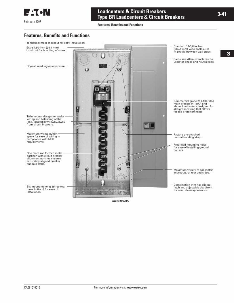
February 2007
CA08101001E For more information visit: www.eaton.com
3-41Loadcenters & Circuit Breakers
3
Type BR Loadcenters & Circuit BreakersFeatures, Benefits and Functions
Features, Benefits and Functions
BR4040B200
Drywall marking on enclosure.
Twin neutral design for easier wiring and balancing of the load, located in wireway, away from circuit breakers.
Maximum wiring gutter space for ease of wiring in compliance with NEC requirements.
One piece roll formed metal backpan with circuit breaker alignment notches ensures accurately aligned breaker and bus stabs.
Six mounting holes (three top, three bottom) for ease of installation.
Maximum variety of concentric knockouts, at rear and sides.
Predrilled mounting holes for ease of installing ground bar kits.
Commercial grade 25 kAIC rated main breaker in 150 A and above loadcenters designed for straight-in wiring that allows for top or bottom feed.
Same size Allen wrench can be used for phase and neutral lugs.
Standard 14-3/8 inches (365.1 mm) wide enclosures fit snugly between wall studs.
Extra 1.50-inch (38.1 mm) knockout for bundling of wires.
Combination trim has sliding latch and adjustable deadfront for neat, clean appearance.
Tangential main knockout for easy installation.
Factory pre-attached neutral bonding strap.
February 2007
3-42
For more information visit: www.eaton.com CA08101001E
Loadcenters & Circuit Breakers
3
Type BR Loadcenters & Circuit BreakersProduct Specifications
Product Specifications
GeneralA. The Contractor shall furnish and
install deadfront loadcenters incorporating circuit breakers of the number, rating and type as specified herein and as shown on the contract drawings.
B. The loadcenter and all components shall be designed, manufactured and tested in accordance with the latest applicable standards of UL, NEMA and NEC including:
1. UL 67 — Standards for Panelboards.
2. UL 50 — Standards for Cabinets and Boxes.
3. UL 489 — Standards for Molded Case Circuit Breakers.
4. UL 869 — Standards for Service Equipment.
5. Federal Specification W-C 375B — Circuit Breakers.
6. Federal Specification W-C P115b — Panel Power Distribution Type 1, Class 2.
QualificationsA. The manufacturer of the load-
center shall be the manufacturer of the circuit breaker within the loadcenter.
B. For the equipment specified herein, the manufacturer shall be ISO 9000 certified.
C. The manufacturer of this equip-ment shall have produced similar electrical equipment for a mini-mum period of seven (7) years.
ManufacturersA. Cutler-Hammer business.
RatingsA. Loadcenters shall be rated for
120/240 Vac and shall have short circuit ratings as shown on the drawings or as herein scheduled, but not less than 10,000 amperes rms symmetrical.
B. Circuit breakers shall be a mini-mum of 125 ampere frame. Circuit breakers 15 through 125 amperes trip size shall take up the same pole spacing.
C. Loadcenters shall be labeled with a UL short circuit rating. When series combination ratings are applied with integral or remote upstream devices, a label shall be provided. Series combination ratings shall cover all trip ratings of installed frames. It shall state the conditions of the UL series ratings including:
1. Size and type of upstream device.
2. Branch devices that can be used.
3. UL series short circuit rating.
ConstructionA. All interiors, with the exception of
the branch circuit breakers, shall be completely factory assembled with main breakers, main lugs, or no main device.
B. Interiors shall be designed so that circuit breakers can be replaced without disturbing adjacent units and without removing the main bus connectors and shall be designed so that circuits may be changed without machining, drilling, or tapping.
C. Physical means shall be provided to prevent the installation of more overcurrent devices than that number for which the enclosure was designed, rated and approved. Half-size breakers shall have a UL listed rejection tab over the line terminals. Loadcenter interiors must have notched stabs to accept these rejection tab class CTL breakers, if required and approved.
BusA. Bus bars for the main and cross
connectors shall be [tin-plated aluminum] [copper] in accordance with Underwriters Laboratories standards. Busing shall be braced throughout to conform to industry standard practice governing short circuit stresses in loadcenters.
Note: Note to spec writer — select one (copper available in limited ratings).
B. Neutral busing shall have a suit-able lug for each outgoing feeder requiring a neutral connection of same ampacity as branch.
Wiring/TerminationA. All wire connectors and terminals
shall be of the anti-turn solderless type and shall be suitable for copper or aluminum wire of the sizes indicated. All connectors must meet the “Requirements for Wire Connectors and Soldering Lugs” as stated in UL 486B.
B. All loadcenters where marked shall be suitable for use with 60°C or 75°C rated wire.
Circuit BreakersA. Circuit breakers shall be molded
case type. Circuit breakers shall have four-rivet construction (GFI Type — 5 rivets). Multipole circuit breakers shall be of a stack pole design to provide electrical phase isolation.
B. Each pole of the circuit breaker will provide inverse time delay overload and instantaneous short circuit protection by means of both thermal and magnetic sensors.
C. The circuit breaker calibration shall not be affected by environmental changes in relative humidity. The thermal bimetal element shall be welded to the steel frame and cali-bration shall be set independent of the molded case by computer controlled equipment.
D. All circuit breakers shall be oper-ated by a toggle-type handle and multipole circuit breakers shall have an internal common trip mechanism. The circuit breakers shall incorporate trip mechanisms that are mechanically trip-free from the handle. The handle position shall provide visual trip indication.
E. Contacts shall be of non-welding silver alloy.
F. All circuit breakers shall have the trip rating inscribed on the handle on each circuit breaker pole. Also, unique color-coded cases that indicate the UL listed 10 kA or 22 kA interrupting ratings. Breakers shall be able to be used as main or branch disconnect devices.
February 2007
CA08101001E For more information visit: www.eaton.com
3-43Loadcenters & Circuit Breakers
3
Type BR Loadcenters & Circuit BreakersProduct Specifications
G. Branch circuit breakers may also be used in the 1/2-inch (12.7 mm) per pole ratings that include 2-pole 1-inch (25.4 mm) wide modules and 4-pole 2-inch (50.8 mm) wide modules. 2-pole circuit breakers must incorporate a common trip mechanism. The exclusive CTL rejection tab feature shall be provided to limit the num-ber of branch devices for a load-center to 42, in compliance with NEC Article 384-15.
H. Circuit breakers shall be com-pletely enclosed in a molded case of thermoset material. No internal aluminum parts shall be used. All internal ferrous parts shall be plated to prevent corrosion.
I. All terminals shall be listed for use with copper or aluminum conduc-tors. Terminals shall be of the box lug or clamp type design. The terminals shall meet UL 486B requirements and shall be suitable for use with either 60°C or 75°C wire.
J. The calibrated bimetal assembly shall be mechanically isolated from the load terminal using a flexible braided copper shunt wire, such that movement of the terminals due to twisting and overtorquing does not affect breaker calibration.
K. Breakers shall be SWD rated and/or HACR rated as required.
L. Arc Fault Interrupting circuit breakers, (AFI), shall be provided on all 15 and 20 ampere single-phase 120/240 Vac circuits except those indicated as remote con-trolled breakers. AFI breakers shall be ”Classified for mitigating the effects of arcing faults,” or con-forming to UL Standard 1699 and as defined by Article 210-12 Section A of the 1999 NEC Code.
Surge Protection DevicesAll 120/240 Vac single-phase load-centers shall have surge protection provided by a CHSPULTRA.
A. The CHSPULTRA, Home Surge Protector shall be supplied in its own enclosure and must be suit-able for flush or surface mounting external of the loadcenter. The device shall provide surge protec-tion for the loadcenter as well as protection for: two incoming tele-phone lines and one incoming coaxial cable. The surge protector shall be installed in accordance to NEC Article 280 and be listed under UL 1449, (2nd Edition), and UL 497A. The units shall be CSA certified and be tested to meet ANSI/IEEE Category B3 and C3 levels. The surge protector shall incorporate a surge plane design to facilitate a common point of grounding for all connected power, telephone, and coaxial incoming conductors. The device shall provide, as a minimum, the following protection:
1. Up to 75 kA surge current pro-tection per phase for transients on the incoming ac line.
2. Up to 10 kA surge protection per pair for telephone lines.
3. Up to 5 kA line to shield (ground) protection for coaxial conductors.
– OR –
A. The surge protection device shall be capable of plugging onto a maximum of two adjacent spaces in a single-phase loadcenter. The device shall provide, as a mini-mum, up to 10 kA surge current protection per phase for transients on the incoming ac line.
B. Surge protection devices must be equipped with LEDs to indicate proper functioning of the internal electronics.
EnclosuresA. Loadcenter shall have NEMA
Type 1 general purpose or NEMA Type 3R rainproof enclosures as indicated on the drawings and shall be surface or combination flush/surface mounted except where noted.
B. Boxes shall be made from galva-nized sheet steel having multiple knockouts. Rainproof boxes shall use galvanized steel or an approved coating system which meets or exceeds standards for outdoor NEMA Type 3R enclo-sures. Boxes shall be of sufficient size to provide at least a minimum code gutter space on all sides.
C. The deadfront shall have an easy adjustment feature for flush applications.
D. Boxes shall be factory assembled into a single rigid structure.
E. Unless otherwise noted on drawings, hinged doors covering all circuit breaker handles shall be included in all trims. Trim doors shall not uncover any live parts in making the circuit breaker handles accessible. If key locks are required, all locks shall be keyed alike.
F. Combination trims for flush and surface panels shall be flat and shall overlap the box by at least 5/8-inch (15.9 mm) all around. Trims shall be mounted by a screwdriver without the need for special tools.
FinishA. Trims shall be bonderized and
finished with a light gray ANSI-61 enamel. The paint finish shall be of a type to which field applied paint will adhere.
Factory TestingA. The standard factory tests shall
be performed on the equipment provided under this section. All tests shall be in accordance with the latest version of UL and NEMA.
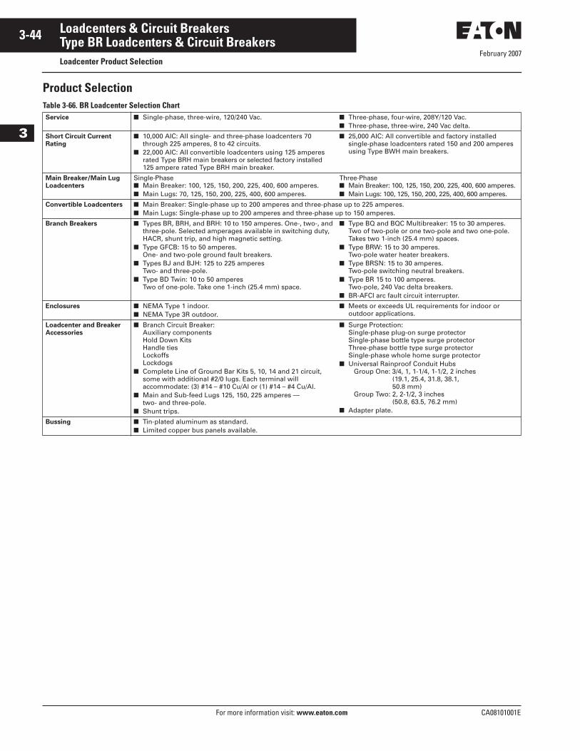
February 2007
3-44
For more information visit: www.eaton.com CA08101001E
Loadcenters & Circuit Breakers
3
Type BR Loadcenters & Circuit BreakersLoadcenter Product Selection
Product SelectionTable 3-66. BR Loadcenter Selection ChartService ■ Single-phase, three-wire, 120/240 Vac. ■ Three-phase, four-wire, 208Y/120 Vac.
■ Three-phase, three-wire, 240 Vac delta.
Short Circuit Current
Rating
■ 10,000 AIC: All single- and three-phase loadcenters 70 through 225 amperes, 8 to 42 circuits.
■ 22,000 AIC: All convertible loadcenters using 125 amperes rated Type BRH main breakers or selected factory installed 125 ampere rated Type BRH main breaker.
■ 25,000 AIC: All convertible and factory installed single-phase loadcenters rated 150 and 200 amperes using Type BWH main breakers.
Main Breaker/Main Lug
Loadcenters
Single-Phase■ Main Breaker: 100, 125, 150, 200, 225, 400, 600 amperes.■ Main Lugs: 70, 125, 150, 200, 225, 400, 600 amperes.
Three-Phase■ Main Breaker: 100, 125, 150, 200, 225, 400, 600 amperes.■ Main Lugs: 100, 125, 150, 200, 225, 400, 600 amperes.
Convertible Loadcenters ■ Main Breaker: Single-phase up to 200 amperes and three-phase up to 225 amperes.■ Main Lugs: Single-phase up to 200 amperes and three-phase up to 150 amperes.
Branch Breakers ■ Types BR, BRH, and BRH: 10 to 150 amperes. One-, two-, and three-pole. Selected amperages available in switching duty, HACR, shunt trip, and high magnetic setting.
■ Type GFCB: 15 to 50 amperes. One- and two-pole ground fault breakers.
■ Types BJ and BJH: 125 to 225 amperes Two- and three-pole.
■ Type BD Twin: 10 to 50 amperes Two of one-pole. Take one 1-inch (25.4 mm) space.
■ Type BQ and BQC Multibreaker: 15 to 30 amperes. Two of two-pole or one two-pole and two one-pole. Takes two 1-inch (25.4 mm) spaces.
■ Type BRW: 15 to 30 amperes.Two-pole water heater breakers.
■ Type BRSN: 15 to 30 amperes.Two-pole switching neutral breakers.
■ Type BR 15 to 100 amperes.Two-pole, 240 Vac delta breakers.
■ BR-AFCI arc fault circuit interrupter.
Enclosures ■ NEMA Type 1 indoor.■ NEMA Type 3R outdoor.
■ Meets or exceeds UL requirements for indoor or outdoor applications.
Loadcenter and Breaker
Accessories
■ Branch Circuit Breaker:Auxiliary componentsHold Down KitsHandle tiesLockoffsLockdogs
■ Complete Line of Ground Bar Kits 5, 10, 14 and 21 circuit, some with additional #2/0 lugs. Each terminal will accommodate: (3) #14 – #10 Cu/Al or (1) #14 – #4 Cu/Al.
■ Main and Sub-feed Lugs 125, 150, 225 amperes — two- and three-pole.
■ Shunt trips.
■ Surge Protection:Single-phase plug-on surge protectorSingle-phase bottle type surge protectorThree-phase bottle type surge protectorSingle-phase whole home surge protector
■ Universal Rainproof Conduit HubsGroup One: 3/4, 1, 1-1/4, 1-1/2, 2 inches
(19.1, 25.4, 31.8, 38.1, 50.8 mm)
Group Two: 2, 2-1/2, 3 inches(50.8, 63.5, 76.2 mm)
■ Adapter plate.
Bussing ■ Tin-plated aluminum as standard.■ Limited copper bus panels available.
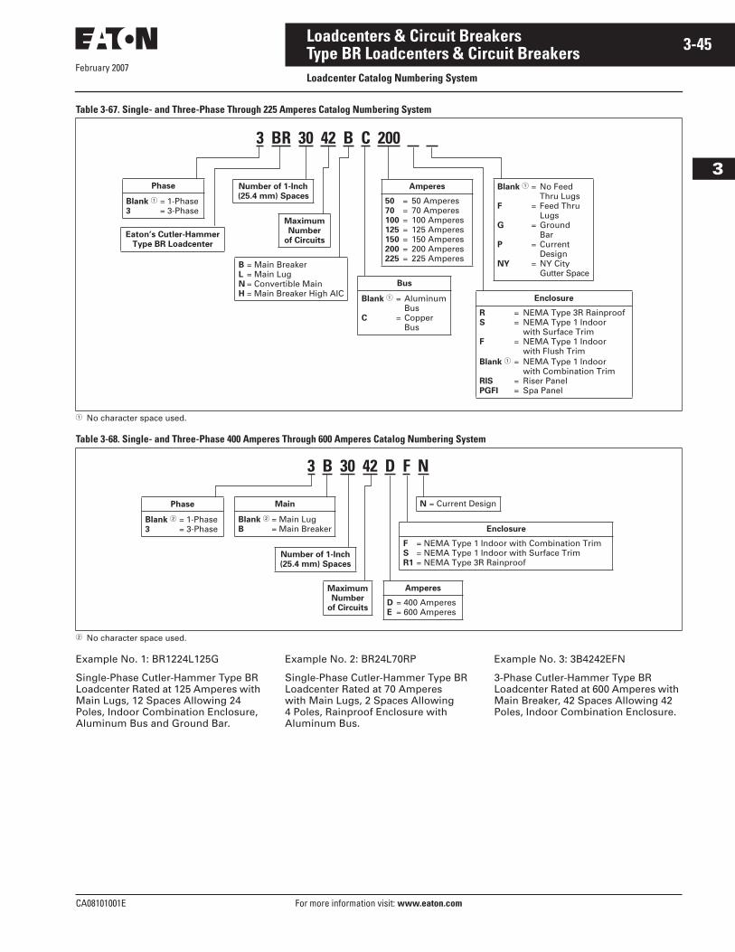
February 2007
CA08101001E For more information visit: www.eaton.com
3-45Loadcenters & Circuit Breakers
3
Type BR Loadcenters & Circuit BreakersLoadcenter Catalog Numbering System
Table 3-67. Single- and Three-Phase Through 225 Amperes Catalog Numbering System
� No character space used.
Table 3-68. Single- and Three-Phase 400 Amperes Through 600 Amperes Catalog Numbering System
� No character space used.
Example No. 1: BR1224L125G
Single-Phase Cutler-Hammer Type BR Loadcenter Rated at 125 Amperes with Main Lugs, 12 Spaces Allowing 24 Poles, Indoor Combination Enclosure, Aluminum Bus and Ground Bar.
Example No. 2: BR24L70RP
Single-Phase Cutler-Hammer Type BR Loadcenter Rated at 70 Amperes with Main Lugs, 2 Spaces Allowing 4 Poles, Rainproof Enclosure with Aluminum Bus.
Example No. 3: 3B4242EFN
3-Phase Cutler-Hammer Type BR Loadcenter Rated at 600 Amperes with Main Breaker, 42 Spaces Allowing 42 Poles, Indoor Combination Enclosure.
3 BR 30 42 B C 200
Bus
Blank � = Aluminum Bus
C = Copper Bus
Eaton’s Cutler-Hammer
Type BR Loadcenter
Phase
Blank � = 1-Phase 3 = 3-Phase
Amperes
50 = 50 Amperes 70 = 70 Amperes 100 = 100 Amperes125 = 125 Amperes150 = 150 Amperes200 = 200 Amperes225 = 225 Amperes
Enclosure
R = NEMA Type 3R Rainproof S = NEMA Type 1 Indoor
with Surface TrimF = NEMA Type 1 Indoor
with Flush Trim Blank � = NEMA Type 1 Indoor
with Combination TrimRIS = Riser PanelPGFI = Spa Panel
Maximum
Number
of Circuits
Number of 1-Inch
(25.4 mm) SpacesBlank � = No Feed
Thru Lugs F = Feed Thru
LugsG = Ground
BarP = Current
DesignNY = NY City
Gutter SpaceB = Main BreakerL = Main LugN = Convertible MainH = Main Breaker High AIC
3 B 30 42 D F N
Phase
Blank � = 1-Phase 3 = 3-Phase Enclosure
F = NEMA Type 1 Indoor with Combination TrimS = NEMA Type 1 Indoor with Surface TrimR1 = NEMA Type 3R Rainproof
Maximum
Number
of Circuits
Number of 1-Inch
(25.4 mm) Spaces
Main
Blank � = Main Lug B = Main Breaker
Amperes
D = 400 Amperes E = 600 Amperes
N = Current Design
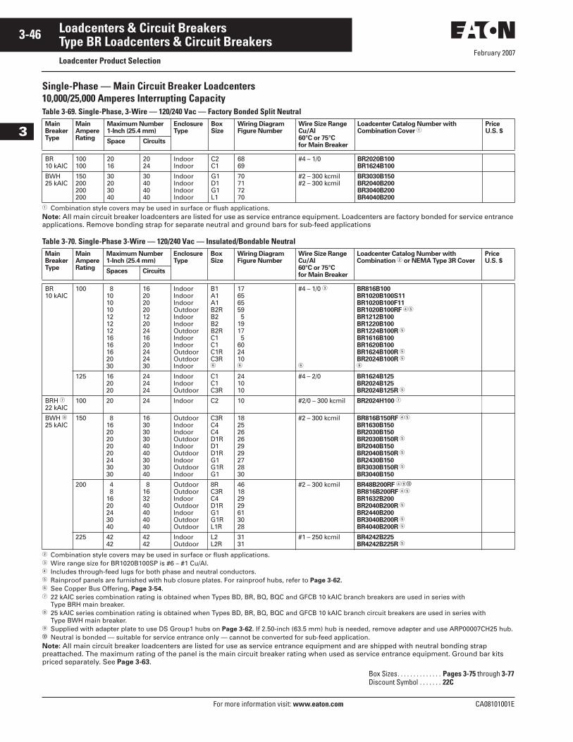
February 2007
3-46
For more information visit: www.eaton.com CA08101001E
Loadcenters & Circuit Breakers
3
Type BR Loadcenters & Circuit BreakersLoadcenter Product Selection
Single-Phase — Main Circuit Breaker Loadcenters10,000/25,000 Amperes Interrupting CapacityTable 3-69. Single-Phase, 3-Wire — 120/240 Vac — Factory Bonded Split Neutral
� Combination style covers may be used in surface or flush applications.Note: All main circuit breaker loadcenters are listed for use as service entrance equipment. Loadcenters are factory bonded for service entrance applications. Remove bonding strap for separate neutral and ground bars for sub-feed applications
Table 3-70. Single-Phase 3-Wire — 120/240 Vac — Insulated/Bondable Neutral
� Combination style covers may be used in surface or flush applications.� Wire range size for BR1020B100SP is #6 – #1 Cu/Al.� Includes through-feed lugs for both phase and neutral conductors.� Rainproof panels are furnished with hub closure plates. For rainproof hubs, refer to Page 3-62.� See Copper Bus Offering, Page 3-54.� 22 kAIC series combination rating is obtained when Types BD, BR, BQ, BQC and GFCB 10 kAIC branch breakers are used in series with
Type BRH main breaker. 25 kAIC series combination rating is obtained when Types BD, BR, BQ, BQC and GFCB 10 kAIC branch circuit breakers are used in series with
Type BWH main breaker. Supplied with adapter plate to use DS Group1 hubs on Page 3-62. If 2.50-inch (63.5 mm) hub is needed, remove adapter and use ARP00007CH25 hub.� Neutral is bonded — suitable for service entrance only — cannot be converted for sub-feed application.Note: All main circuit breaker loadcenters are listed for use as service entrance equipment and are shipped with neutral bonding strap preattached. The maximum rating of the panel is the main circuit breaker rating when used as service entrance equipment. Ground bar kits priced separately. See Page 3-63.
MainBreakerType
MainAmpereRating
Maximum Number1-Inch (25.4 mm)
EnclosureType
BoxSize
Wiring DiagramFigure Number
Wire Size RangeCu/Al60°C or 75°Cfor Main Breaker
Loadcenter Catalog Number withCombination Cover �
PriceU.S. $
Space Circuits
BR10 kAIC
100100
2016
2024
IndoorIndoor
C2C1
6869
#4 – 1/0 BR2020B100BR1624B100
BWH25 kAIC
150200200200
30203040
30404040
IndoorIndoorIndoorIndoor
G1D1G1L1
70717270
#2 – 300 kcmil#2 – 300 kcmil
BR3030B150BR2040B200BR3040B200BR4040B200
MainBreakerType
MainAmpereRating
Maximum Number1-Inch (25.4 mm)
EnclosureType
BoxSize
Wiring DiagramFigure Number
Wire Size RangeCu/Al60°C or 75°Cfor Main Breaker
Loadcenter Catalog Number withCombination � or NEMA Type 3R Cover
PriceU.S. $
Spaces Circuits
BR10 kAIC
100 81010101212121616162030
162020201220241620242430
IndoorIndoorIndoorOutdoorIndoorIndoorOutdoorIndoorIndoorOutdoorOutdoorIndoor
B1A1A1B2RB2B2B2RC1C1C1RC3R�
17656559 51917 5602410�
#4 – 1/0 �
�
BR816B100BR1020B100S11BR1020B100F11BR1020B100RF ��
BR1212B100BR1220B100BR1224B100R �
BR1616B100BR1620B100BR1624B100R �
BR2024B100R ��
125 162020
242424
IndoorIndoorOutdoor
C1C1C3R
241010
#4 – 2/0 BR1624B125BR2024B125BR2024B125R �
BRH �22 kAIC
100 20 24 Indoor C2 10 #2/0 – 300 kcmil BR2024H100 �
BWH 25 kAIC
150 81620202020243030
163030304040303040
OutdoorIndoorIndoorOutdoorIndoorOutdoorIndoorOutdoorIndoor
C3RC4C4D1RD1D1RG1G1RG1
182526262929272830
#2 – 300 kcmil BR816B150RF ��
BR1630B150BR2030B150BR2030B150R �
BR2040B150BR2040B150R �
BR2430B150BR3030B150R �
BR3040B150
200 4 81620243040
8163240404040
OutdoorOutdoorIndoorOutdoorIndoorOutdoorOutdoor
8RC3RC4D1RG1G1RL1R
46182929613028
#2 – 300 kcmil BR48B200RF ��
BR816B200RF ��
BR1632B200BR2040B200R �
BR2440B200BR3040B200R �
BR4040B200R �
225 4242
4242
IndoorOutdoor
L2L2R
3131
#1 – 250 kcmil BR4242B225BR4242B225R �
Box Sizes. . . . . . . . . . . . . . Pages 3-75 through 3-77Discount Symbol . . . . . . . 22C
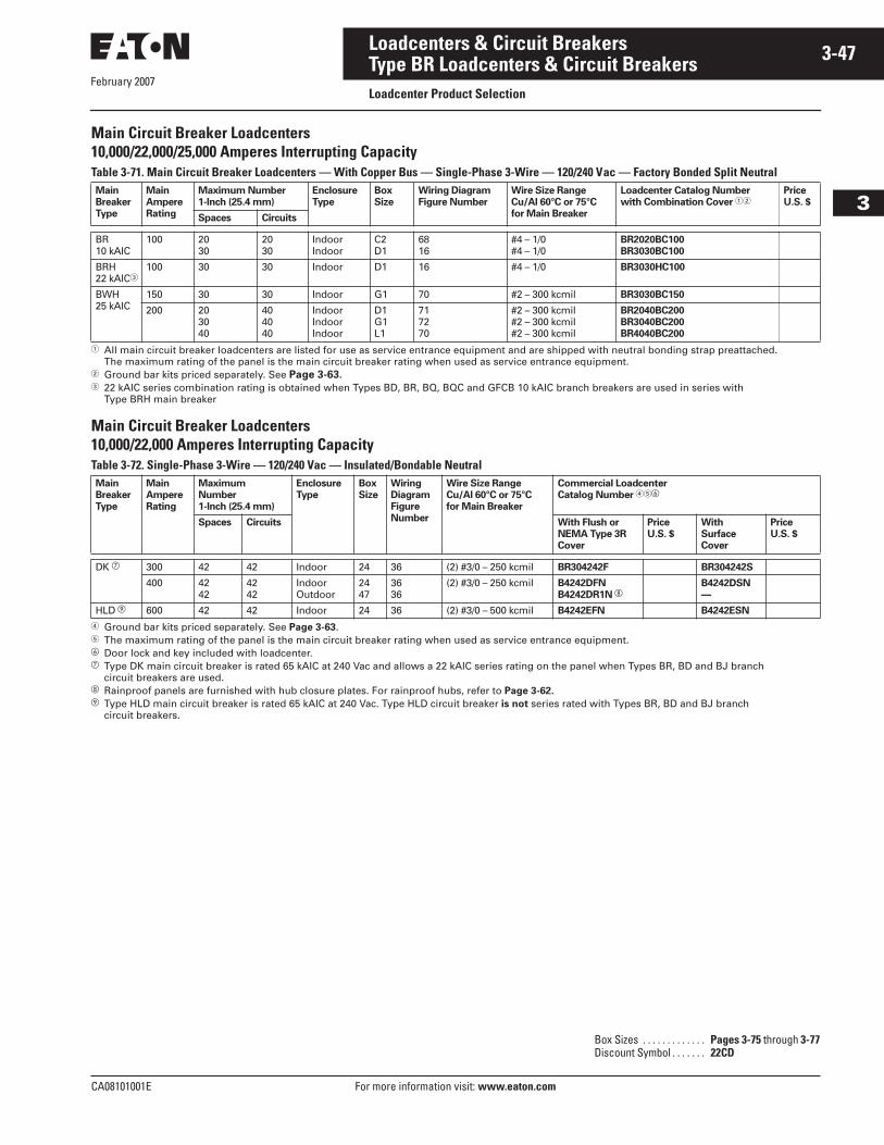
February 2007
CA08101001E For more information visit: www.eaton.com
3-47Loadcenters & Circuit Breakers
3
Type BR Loadcenters & Circuit BreakersLoadcenter Product Selection
Main Circuit Breaker Loadcenters10,000/22,000/25,000 Amperes Interrupting CapacityTable 3-71. Main Circuit Breaker Loadcenters — With Copper Bus — Single-Phase 3-Wire — 120/240 Vac — Factory Bonded Split Neutral
� All main circuit breaker loadcenters are listed for use as service entrance equipment and are shipped with neutral bonding strap preattached. The maximum rating of the panel is the main circuit breaker rating when used as service entrance equipment.
� Ground bar kits priced separately. See Page 3-63.� 22 kAIC series combination rating is obtained when Types BD, BR, BQ, BQC and GFCB 10 kAIC branch breakers are used in series with
Type BRH main breaker
Main Circuit Breaker Loadcenters10,000/22,000 Amperes Interrupting CapacityTable 3-72. Single-Phase 3-Wire — 120/240 Vac — Insulated/Bondable Neutral
� Ground bar kits priced separately. See Page 3-63.� The maximum rating of the panel is the main circuit breaker rating when used as service entrance equipment.� Door lock and key included with loadcenter. Type DK main circuit breaker is rated 65 kAIC at 240 Vac and allows a 22 kAIC series rating on the panel when Types BR, BD and BJ branch
circuit breakers are used. Rainproof panels are furnished with hub closure plates. For rainproof hubs, refer to Page 3-62.� Type HLD main circuit breaker is rated 65 kAIC at 240 Vac. Type HLD circuit breaker is not series rated with Types BR, BD and BJ branch
circuit breakers.
Main
Breaker
Type
Main
Ampere
Rating
Maximum Number
1-Inch (25.4 mm)
Enclosure
Type
Box
Size
Wiring Diagram
Figure Number
Wire Size Range
Cu/Al 60°C or 75°C
for Main Breaker
Loadcenter Catalog Number
with Combination Cover ��Price
U.S. $
Spaces Circuits
BR10 kAIC
100 2030
2030
IndoorIndoor
C2D1
6816
#4 – 1/0#4 – 1/0
BR2020BC100
BR3030BC100
BRH22 kAIC�
100 30 30 Indoor D1 16 #4 – 1/0 BR3030HC100
BWH25 kAIC
150 30 30 Indoor G1 70 #2 – 300 kcmil BR3030BC150
200 203040
404040
IndoorIndoorIndoor
D1G1L1
717270
#2 – 300 kcmil#2 – 300 kcmil#2 – 300 kcmil
BR2040BC200
BR3040BC200
BR4040BC200
Main
Breaker
Type
Main
Ampere
Rating
Maximum
Number
1-Inch (25.4 mm)
Enclosure
Type
Box
Size
Wiring
Diagram
Figure
Number
Wire Size Range
Cu/Al 60°C or 75°C
for Main Breaker
Commercial Loadcenter
Catalog Number ���
Spaces Circuits With Flush or
NEMA Type 3R
Cover
Price
U.S. $
With
Surface
Cover
Price
U.S. $
DK 300 42 42 Indoor 24 36 (2) #3/0 – 250 kcmil BR304242F BR304242S
400 4242
4242
IndoorOutdoor
2447
3636
(2) #3/0 – 250 kcmil B4242DFN
B4242DR1N B4242DSN
—
HLD � 600 42 42 Indoor 24 36 (2) #3/0 – 500 kcmil B4242EFN B4242ESN
Box Sizes . . . . . . . . . . . . . Pages 3-75 through 3-77Discount Symbol . . . . . . . 22CD
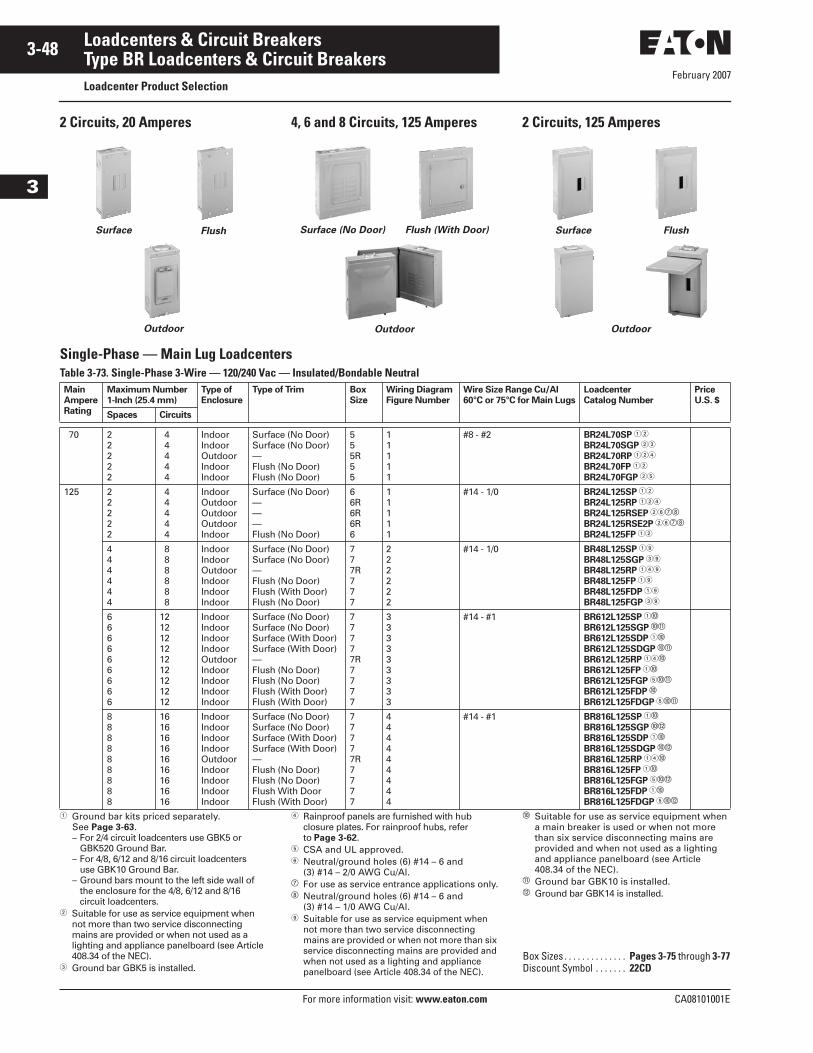
February 2007
3-48
For more information visit: www.eaton.com CA08101001E
Loadcenters & Circuit Breakers
3
Type BR Loadcenters & Circuit BreakersLoadcenter Product Selection
2 Circuits, 20 Amperes 4, 6 and 8 Circuits, 125 Amperes 2 Circuits, 125 Amperes
Single-Phase — Main Lug LoadcentersTable 3-73. Single-Phase 3-Wire — 120/240 Vac — Insulated/Bondable Neutral
� Ground bar kits priced separately. See Page 3-63.– For 2/4 circuit loadcenters use GBK5 or
GBK520 Ground Bar.– For 4/8, 6/12 and 8/16 circuit loadcenters
use GBK10 Ground Bar.– Ground bars mount to the left side wall of
the enclosure for the 4/8, 6/12 and 8/16 circuit loadcenters.
� Suitable for use as service equipment when not more than two service disconnecting mains are provided or when not used as a lighting and appliance panelboard (see Article 408.34 of the NEC).
� Ground bar GBK5 is installed.
� Rainproof panels are furnished with hubclosure plates. For rainproof hubs, referto Page 3-62.
� CSA and UL approved.� Neutral/ground holes (6) #14 – 6 and
(3) #14 – 2/0 AWG Cu/Al. For use as service entrance applications only. Neutral/ground holes (6) #14 – 6 and
(3) #14 – 1/0 AWG Cu/Al. Suitable for use as service equipment when
not more than two service disconnecting mains are provided or when not more than six service disconnecting mains are provided and when not used as a lighting and appliance panelboard (see Article 408.34 of the NEC).
� Suitable for use as service equipment when a main breaker is used or when not more than six service disconnecting mains are provided and when not used as a lighting and appliance panelboard (see Article 408.34 of the NEC).
� Ground bar GBK10 is installed.� Ground bar GBK14 is installed.
Surface Flush
Outdoor Outdoor
Surface (No Door) Flush (With Door) Surface Flush
Outdoor
Main
Ampere
Rating
Maximum Number
1-Inch (25.4 mm)
Type of
Enclosure
Type of Trim Box
Size
Wiring Diagram
Figure Number
Wire Size Range Cu/Al
60°C or 75°C for Main Lugs
Loadcenter
Catalog Number
Price
U.S. $
Spaces Circuits
70 22222
4 4 4 4 4
IndoorIndoorOutdoorIndoorIndoor
Surface (No Door)Surface (No Door)—Flush (No Door)Flush (No Door)
555R55
11111
#8 - #2 BR24L70SP ��
BR24L70SGP ��
BR24L70RP ���
BR24L70FP ��
BR24L70FGP ��
125 22222
4 4 4 4 4
IndoorOutdoorOutdoorOutdoorIndoor
Surface (No Door)———Flush (No Door)
66R6R6R6
11111
#14 - 1/0 BR24L125SP ��
BR24L125RP ���
BR24L125RSEP ��
BR24L125RSE2P ��
BR24L125FP ��
444444
8 8 8 8 8 8
IndoorIndoorOutdoorIndoorIndoorIndoor
Surface (No Door)Surface (No Door)—Flush (No Door)Flush (With Door)Flush (No Door)
777R777
222222
#14 - 1/0 BR48L125SP �
BR48L125SGP �
BR48L125RP ��
BR48L125FP �
BR48L125FDP �
BR48L125FGP �
666666666
121212121212121212
IndoorIndoorIndoorIndoorOutdoorIndoorIndoorIndoorIndoor
Surface (No Door)Surface (No Door)Surface (With Door)Surface (With Door)—Flush (No Door)Flush (No Door)Flush (With Door)Flush (With Door)
77777R7777
333333333
#14 - #1 BR612L125SP ��
BR612L125SGP ��
BR612L125SDP ��
BR612L125SDGP ��
BR612L125RP ���
BR612L125FP ��
BR612L125FGP ���
BR612L125FDP �
BR612L125FDGP ���
888888888
161616161616161616
IndoorIndoorIndoorIndoorOutdoorIndoorIndoorIndoorIndoor
Surface (No Door)Surface (No Door)Surface (With Door)Surface (With Door)—Flush (No Door)Flush (No Door)Flush With DoorFlush (With Door)
77777R7777
444444444
#14 - #1 BR816L125SP ��
BR816L125SGP ��
BR816L125SDP ��
BR816L125SDGP ��
BR816L125RP ���
BR816L125FP ��
BR816L125FGP ���
BR816L125FDP ��
BR816L125FDGP ���
Box Sizes . . . . . . . . . . . . . . Pages 3-75 through 3-77Discount Symbol . . . . . . . 22CD
February 2007
CA08101001E For more information visit: www.eaton.com
3-49Loadcenters & Circuit Breakers
3
Type BR Loadcenters & Circuit BreakersLoadcenter Product Selection
Single-Phase — Main Lug LoadcentersTable 3-73. Single-Phase 3-Wire — 120/240 Vac — Insulated/Bondable Neutral (Continued)
� Ground bar kits priced separately unless otherwise noted. See Page 3-63.� Has notch for BREQS125 hold-down kit.� Single, movable neutral is provided.� Combination cover style.� Suitable for use as service equipment when not more than six main disconnecting means are provided and when not used as a lighting and appliance
panelboard (see Article 408.34 of the NEC).� Ground bar GBK10 installed.� Ground bars GBK5 and GBK520 installed. Rainproof panels are furnished with hub closure plates. For rainproof hubs, refer to Page 3-62. Ground bar GBK1220 installed.� Has notch for BRHDK125 hold-down kit.� Includes through-feed lugs for both phase and neutral conductors.
Single-Phase — Main Lug Loadcenters, Non-MetallicTable 3-74. Single-Phase 3-Wire — 120/240 Vac — Insulated/Bondable Neutral
� Suitable for use as service equipment when not more than six main disconnecting means are provided and when not used as a lighting and appliance panelboard (see Article 408.34 of the NEC).
� This device has no main lugs. A Type BR or BD breaker is required to be backfed to supply power to branch breakers. This device is single-phase 120 Vac only. With the use of three Type BR breakers there are two branch circuits available. With the use of three Type BD breakers there are five branch circuits available.
� Includes GB4NM ground bar.� 2460 RNM uses the non-metrical ACD enclosure. See ACD Section for dimensions.
Main
Ampere
Rating
Maximum Number
1-Inch (25.4 mm)
Enclosure
Type
Box
Size
Wiring Diagram
Figure Number
Wire Size Range
Cu/Al 60°C or 75°C
for Main Lugs
Loadcenter Catalog Number
with Combination or
NEMA Type 3R Cover �
Price
U.S. $
Spaces Circuits
125 121212121216161616202020202424
122424242416242424202424242424
IndoorIndoorIndoorIndoorOutdoorIndoorIndoorIndoorOutdoorIndoorIndoorIndoorOutdoorIndoorIndoor
B1B1B1B1B1RB2B2B2B2RC1C1C1C1RC2C2
966665777588855
#6 – 2/0 BR1212L125 ����
BR1224L125 ���
BR1224L125G ����
BR1224L125DG ����
BR1224L125R ��
BR1616L125 ��
BR1624L125 ��
BR1624L125G ���
BR1624L125R �
BR2020L125 ��
BR2024L125 ��
BR2024L125G ��
BR2024L125R �
BR2424L125 ��
BR2424L125G ��
150 1620
3030
IndoorIndoor
C2C2
6211
#1 – 300 kcmil BR1630L150 ��
BR2030L150 ��
200 8121220202024303030404040
16242440404040404040404040
OutdoorIndoorOutdoorIndoorIndoorOutdoorIndoorIndoorIndoorOutdoorIndoorIndoorOutdoor
B2RB2B2RC2C2C3RC4D1D1D1RG1G1G1R
63121212121264151515555
#1 – 300 kcmil BR816L200RF ��
BR1224L200 ���
BR1224L200R ��
BR2040L200 ��
BR2040L200G ��
BR2040L200R �
BR2440L200 ��
BR3040L200 ��
BR3040L200G ��
BR3040L200R �
BR4040L200 ��
BR4040L200G ��
BR4040L200R �
225 4242
4242
IndoorOutdoor
L1L1R
2020
#1 – 300 kcmil BR4242L225
BR4242L225R
Main
Ampere
Rating
Maximum Number
1-Inch (25.4 mm)
Enclosure
Type
Type of Trim Box
Size
Wiring Diagram
Figure Number
Wire Size Range
Cu/Al 60°C or 75°C
for Main Lugs
Loadcenter
Catalog Number
Price
U.S. $
Spaces Circuits
40 � ��
��
IndoorIndoor
Flush No DoorSurface No Door
22
6666
� TT120FLGNM ��
TT120SLGNM ��
60 22222
44444
IndoorIndoorIndoorIndoorOutdoor
Flush No DoorSurface No DoorFlush No DoorSurface No Door—
2222�
11111
#14 – 2 2460FNM
2460SNM
2460FGNM �
2460SGNM �
2460RNM
Box Sizes . . . . . . . . . . . . . Pages 3-75 through 3-77Discount Symbol . . . . . . . 22CD
February 2007
3-50
For more information visit: www.eaton.com CA08101001E
Loadcenters & Circuit Breakers
3
Type BR Loadcenters & Circuit BreakersLoadcenter Product Selection
Single-Phase — Main Lug Loadcenters — 400 and 600 AmpereTable 3-75. Single-Phase 3-Wire — 120/240 Vac — Insulated/Bondable Neutral
� Ground bar kits priced separately unless otherwise noted. See Page 3-63.� Has notch for BRHDK125 hold-down kit.� Ground bar GBK8 installed.� Rainproof panels are furnished with hub closure plates. For rainproof hubs, refer to Page 3-62.� Suitable for use as service equipment when not more than six main disconnecting means are provided and when not used as a lighting and appliance
panelboard (see Article 408.34 of the NEC).
Table 3-76. Single-Phase 3-Wire — 120/240 Vac — Single Neutral with Copper Bus
Main
Ampere
Rating
Maximum Number
1-Inch (25.4 mm)
Enclosure
Type
Box
Size
Wiring Diagram
Figure Number
Wire Size Range
Cu/Al 60°C or 75°C
for Main Lugs
Commercial Loadcenter
Catalog Number ���
Spaces Circuits With Flush or NEMA
Type 3R Cover
Price
U.S. $
With Surface
Cover
Price
U.S. $
400 1212244242
2424424242
IndoorOutdoorIndoorIndoorOutdoor
1942202246
4444211414
(1) #4/0 – 750 kcmil or(2) #3/0 – 400 kcmil
—
1224DR1N ��
—
4242DFN
4242DR1N �
1224DSN �
—
2442DSN
4242DSN
—
600 42 42 Indoor 22 14 (2) #2 – 500 kcmil — 4242ESN
Main
Ampere
Rating
Maximum Number
1-Inch (25.4 mm)
Enclosure
Type
Type
of Trim
Box
Size
Wiring Diagram
Figure Number
Wire Size Range
Cu/Al 60°C or 75°C
for Main Lugs
Loadcenter
Catalog Number
Price
U.S. $
Spaces Circuits
125 88
1616
IndoorIndoor
Surface w/doorFlush w/door
77
77
#14 – 1 BR816LC125SDP
BR816LC125FDP
Box Sizes . . . . . . . . . . . . . . Pages 3-75 through 3-77Discount Symbol . . . . . . . 22CD
February 2007
CA08101001E For more information visit: www.eaton.com
3-51Loadcenters & Circuit Breakers
3
Type BR Loadcenters & Circuit BreakersLoadcenter Product Selection
3-Phase — Main Circuit Breaker Loadcenters10,000 Amperes Interrupting CapacityTable 3-77. 3-Phase 4-Wire — 208Y/120 Vac or 240 Vac Insulated/Bondable Neutral
� All main circuit breaker loadcenters are listed for use as service entrance equipment and are shipped with a neutral bonding strap pre-attached (commercial loadcenters do not have a pre-attached bonding strip). The maximum main rating of the panel is the main circuit breaker rating when used as service entrance equipment.
� Ground bar kits priced separately. See Page 3-63.� Rainproof loadcenters are furnished with hub closure plates. For rainproof hubs, refer to Page 3-62.
3-Phase — Main Circuit Breaker Loadcenters22,000/65,000 Amperes Interrupting CapacityTable 3-78. 3-Phase, 4-Wire — 208Y/120 Vac or 240 Vac Insulated/Bondable Neutral
� All main circuit breaker loadcenters are listed for use as service entrance equipment and are shipped with a neutral bonding strap pre-attached (commercial loadcenters do not have a pre-attached bonding strip). The maximum main rating of the panel is the main circuit breaker rating when used as service entrance equipment.
� Ground bar kits priced separately. See Page 3-63.� Door lock and key included with loadcenter. Type DK main circuit breaker is rated 65 kAIC at 240 Vac and allows a 22 kAIC series rating on the loadcenter when Types BR, BD and BJ branch circuit
breakers are used. Rainproof loadcenters are furnished with hub closure plates. For rainproof hubs, refer to Page 3-62. The LD main circuit breaker is rated 65 kAIC at 240 Vac. Type LD circuit breaker is not series rated with Types BR, BD and BJ branch circuit breakers.
3-Phase — High Interrupting Rated Main Circuit Breaker Loadcenters22,000/100,000 Amperes Interrupting CapacityTable 3-79. 3-Phase 4-Wire — 208Y/120 Vac or 240 Vac Insulated/Bondable Neutral
� All main circuit breaker loadcenters are listed for use as service entrance equipment and are shipped with a neutral bonding strap pre-attached.� Ground bar kits priced separately.� 22,000 AIC series combination rating is obtained when Types BD, BR, BQ, BQC and GFGB branch breakers are used with BRH main.� 100,000 AIC series combination rating is obtained when Types BD, BR, BQ, BQC and GFGB branch breakers are used with CHH main
Main
Breaker
Type
Main
Ampere
Rating
Maximum Number
1-Inch (25.4 mm)
Enclosure
Type
Box
Size
Wiring Diagram
Figure Number
Wire Size Range
Cu/Al 60°C or 75°C
for Main Breaker
Loadcenter Catalog Number ��
(With Combination or
NEMA Type 3R Cover)
Price
U.S. $
Spaces Circuits
BR10 kAIC
100 1212
2424
IndoorOutdoor
C1C1R
6565
#4 – 1/0 3BR1224B100
3BR1224B100R �
CC10 kAIC
150 3030
4242
IndoorOutdoor
L1L1R
4141
#1 – 3/0 3BR3042B150
3BR3042B150R �
200 30304242
42424242
IndoorOutdoorIndoorOutdoor
L1L1RL2L2R
41414343
#1 – 250 kcmil 3BR3042B200
3BR3042B200R �
3BR4242B200
3BR4242B200R �
225 4242
4242
IndoorOutdoor
L2L2R
4343
#1 – 300 kcmil 3BR4242B225
3BR4242B225R �
Main
Breaker
Type
Main
Ampere
Rating
Maximum Number
1-Inch (25.4 mm)
Enclosure
Type
Box
Size
Wiring Diagram
Figure Number
Wire Size Range
Cu/Al 60°C or 75°C
for Main Breaker
Commercial Loadcenter
Catalog Number ���Price
U.S. $
Spaces Circuits With Combination or
NEMA Type 3R Cover
DK 22 kAIC
400 4242
4242
IndoorOutdoor
2447
4242
(2) #3/0 – 250 kcmil 3B4242DFN
3B4242DR1N
LD 600 42 42 Indoor 24 42 (2) #3/0 – 500 kcmil 3B4242EFN
Main
Breaker
Type
Main
Ampere
Rating
Maximum Number
1-Inch (25.4 mm)
Enclosure
Type
Box
Size
Wire Size Range Cu/Al
60°C or 75°C for
Main Breaker
Loadcenter
Catalog Number ��
Spaces Poles with Combination Cover with Surface Cover
BRH 22 kAIC �
100 12 24 Indoor C1 #4 – 1/0 3BR1224H100 3BR1224H100S
CHH 100 kAIC �
150 30 42 Indoor L1 #1 – 250 kcmil 3BR3042H150 3BR3042H150S
CHH 100 kAIC �
200 3042
4242
IndoorIndoor
L1L2
#1 – 250 kcmil 3BR3042H200
3BR4242H200
3BR3042H200S
3BR4242H200S
Box Sizes . . . . . . . . . . . . Pages 3-75 through 3-77Discount Symbol . . . . . . 22CD
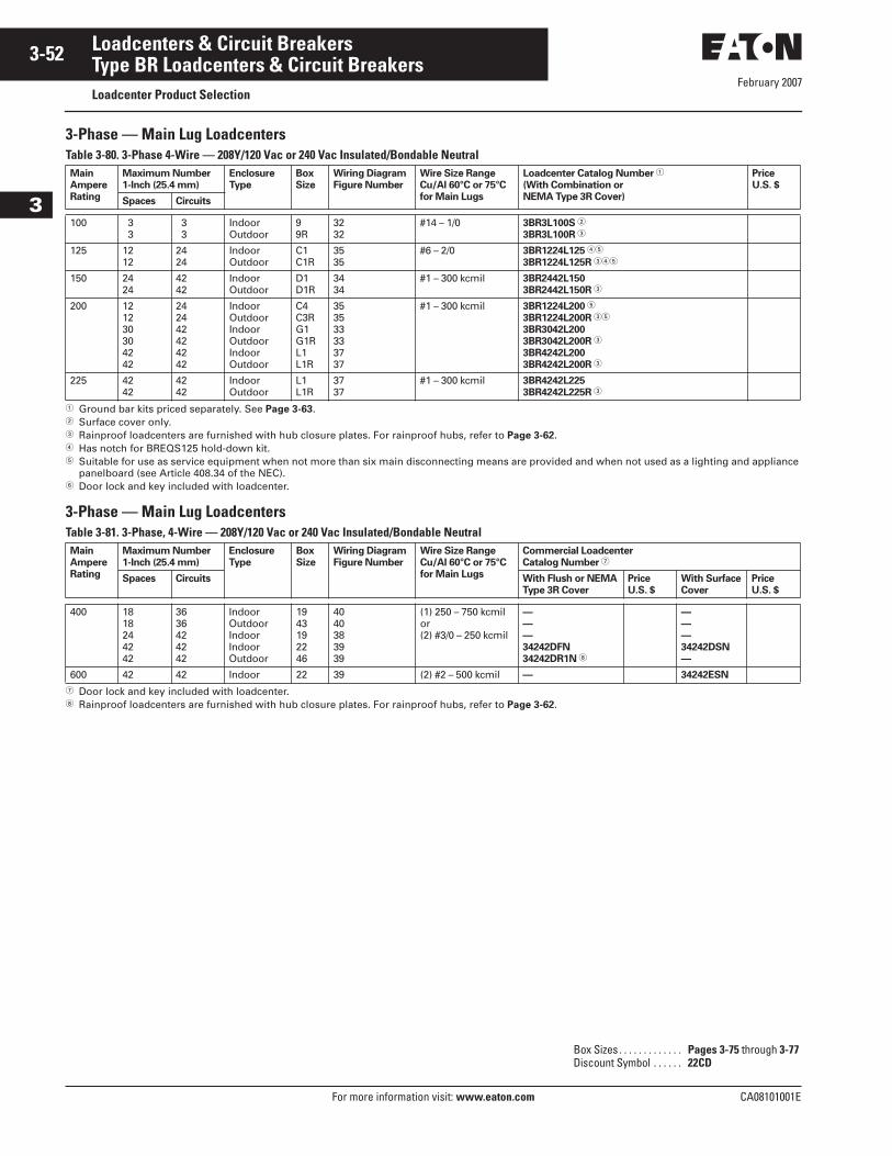
February 2007
3-52
For more information visit: www.eaton.com CA08101001E
Loadcenters & Circuit Breakers
3
Type BR Loadcenters & Circuit BreakersLoadcenter Product Selection
3-Phase — Main Lug LoadcentersTable 3-80. 3-Phase 4-Wire — 208Y/120 Vac or 240 Vac Insulated/Bondable Neutral
� Ground bar kits priced separately. See Page 3-63.� Surface cover only.� Rainproof loadcenters are furnished with hub closure plates. For rainproof hubs, refer to Page 3-62.� Has notch for BREQS125 hold-down kit.� Suitable for use as service equipment when not more than six main disconnecting means are provided and when not used as a lighting and appliance
panelboard (see Article 408.34 of the NEC).� Door lock and key included with loadcenter.
3-Phase — Main Lug LoadcentersTable 3-81. 3-Phase, 4-Wire — 208Y/120 Vac or 240 Vac Insulated/Bondable Neutral
� Door lock and key included with loadcenter. Rainproof loadcenters are furnished with hub closure plates. For rainproof hubs, refer to Page 3-62.
Main
Ampere
Rating
Maximum Number
1-Inch (25.4 mm)
Enclosure
Type
Box
Size
Wiring Diagram
Figure Number
Wire Size Range
Cu/Al 60°C or 75°C
for Main Lugs
Loadcenter Catalog Number �
(With Combination or
NEMA Type 3R Cover)
Price
U.S. $
Spaces Circuits
100 33
33
IndoorOutdoor
99R
3232
#14 – 1/0 3BR3L100S �
3BR3L100R �
125 1212
2424
IndoorOutdoor
C1C1R
3535
#6 – 2/0 3BR1224L125 ��
3BR1224L125R ���
150 2424
4242
IndoorOutdoor
D1D1R
3434
#1 – 300 kcmil 3BR2442L150
3BR2442L150R �
200 121230304242
242442424242
IndoorOutdoorIndoorOutdoorIndoorOutdoor
C4C3RG1G1RL1L1R
353533333737
#1 – 300 kcmil 3BR1224L200 �
3BR1224L200R ��
3BR3042L200
3BR3042L200R �
3BR4242L200
3BR4242L200R �
225 4242
4242
IndoorOutdoor
L1L1R
3737
#1 – 300 kcmil 3BR4242L225
3BR4242L225R �
Main
Ampere
Rating
Maximum Number
1-Inch (25.4 mm)
Enclosure
Type
Box
Size
Wiring Diagram
Figure Number
Wire Size Range
Cu/Al 60°C or 75°C
for Main Lugs
Commercial Loadcenter
Catalog Number �
Spaces Circuits With Flush or NEMA
Type 3R Cover
Price
U.S. $
With Surface
Cover
Price
U.S. $
400 1818244242
3636424242
IndoorOutdoorIndoorIndoorOutdoor
1943192246
4040383939
(1) 250 – 750 kcmilor(2) #3/0 – 250 kcmil
—
—
—
34242DFN
34242DR1N
—
—
—
34242DSN
—
600 42 42 Indoor 22 39 (2) #2 – 500 kcmil — 34242ESN
Box Sizes . . . . . . . . . . . . . Pages 3-75 through 3-77Discount Symbol . . . . . . 22CD
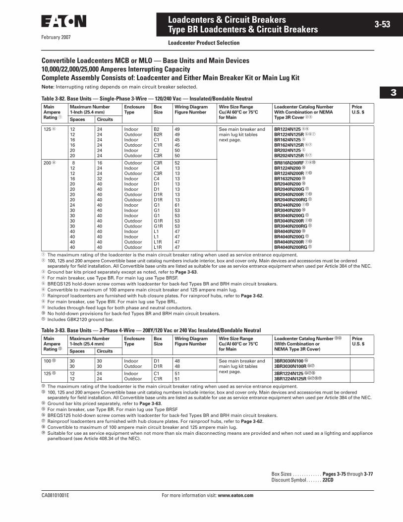
February 2007
CA08101001E For more information visit: www.eaton.com
3-53Loadcenters & Circuit Breakers
3
Type BR Loadcenters & Circuit BreakersLoadcenter Product Selection
Convertible Loadcenters MCB or MLO — Base Units and Main Devices10,000/22,000/25,000 Amperes Interrupting CapacityComplete Assembly Consists of: Loadcenter and Either Main Breaker Kit or Main Lug KitNote: Interrupting rating depends on main circuit breaker selected.
Table 3-82. Base Units — Single-Phase 3-Wire — 120/240 Vac — Insulated/Bondable Neutral
� The maximum rating of the loadcenter is the main circuit breaker rating when used as service entrance equipment.� 100, 125 and 200 ampere Convertible base unit catalog numbers include interior, box and cover only. Main devices and accessories must be ordered
separately for field installation. All Convertible base units are listed as suitable for use as service entrance equipment when used per Article 384 of the NEC.� Ground bar kits priced separately except as noted, refer to Page 3-63.� For main breaker, use Type BR. For main lug use Type BRSF.� BREQS125 hold-down screw comes with loadcenter for back-fed Types BR and BRH main circuit breakers.� Convertible to maximum of 100 ampere main circuit breaker and 125 ampere main lug.� Rainproof loadcenters are furnished with hub closure plates. For rainproof hubs, refer to Page 3-62. For main breaker, use Type BW. For main lug use Type BRL. Includes through-feed lugs for both phase and neutral conductors.� No hold-down provisions for back-fed Types BR and BRH main circuit breakers.� Includes GBK2120 ground bar.
Table 3-83. Base Units — 3-Phase 4-Wire — 208Y/120 Vac or 240 Vac Insulated/Bondable Neutral
� The maximum rating of the loadcenter is the main circuit breaker rating when used as service entrance equipment.� 100, 125 and 200 ampere Convertible base unit catalog numbers include interior, box and cover only. Main devices and accessories must be ordered
separately for field installation. All Convertible base units are listed as suitable for use as service entrance equipment when used per Article 384 of the NEC.� Ground bar kits priced separately, refer to Page 3-63.� For main breaker, use Type BR. For main lug use Type BRSF� BREQS125 hold-down screw comes with loadcenter for back-fed Types BR and BRH main circuit breakers. Rainproof loadcenters are furnished with hub closure plates. For rainproof hubs, refer to Page 3-62.� Convertible to maximum of 100 ampere main circuit breaker and 125 ampere main lug.� Suitable for use as service equipment when not more than six main disconnecting means are provided and when not used as a lighting and appliance
panelboard (see Article 408.34 of the NEC).
Main
Ampere
Rating �
Maximum Number
1-Inch (25.4 mm)
Enclosure
Type
Box
Size
Wiring Diagram
Figure Number
Wire Size Range
Cu/Al 60°C or 75°C
for Main
Loadcenter Catalog Number
With Combination or NEMA
Type 3R Cover ��
Price
U.S. $
Spaces Circuits
125 � 121216162020
242424242424
IndoorOutdoorIndoorOutdoorIndoorOutdoor
B2B2RC1C1RC2C3R
494945455050
See main breaker andmain lug kit tablesnext page.
BR1224N125 ��
BR1224N125R ���
BR1624N125 �
BR1624N125R ��
BR2024N125 �
BR2024N125R ��
200 812121620202020243030303040404040
1624243240404040404040404040404040
OutdoorIndoorOutdoorIndoorIndoorIndoorOutdoorOutdoorIndoorIndoorIndoorOutdoorOutdoorIndoorIndoorOutdoorOutdoor
C3RC4C3RC4D1D1D1RD1RG1G1G1G1RG1RL1L1L1RL1R
5213131313131313615353535347474747
BR816N200RF ��
BR1224N200 �
BR1224N200R ��
BR1632N200 �
BR2040N200 �
BR2040N200G �
BR2040N200R ��
BR2040N200RG �
BR2440N200 ��
BR3040N200 �
BR3040N200G �
BR3040N200R ��
BR3040N200RG �
BR4040N200 �
BR4040N200G �
BR4040N200R ��
BR4040N200RG �
Main
Ampere
Rating �
Maximum Number
1-Inch (25.4 mm)
Enclosure
Type
Box
Size
Wiring Diagram
Figure Number
Wire Size Range
Cu/Al 60°C or 75°C
for Main
Loadcenter Catalog Number ��
(With Combination or
NEMA Type 3R Cover)
Price
U.S. $
Spaces Circuits
100 � 3030
3030
IndoorOutdoor
D1D1R
4848
See main breaker andmain lug kit tablesnext page.
3BR3030N100 �
3BR3030N100R �
125 � 1212
2424
IndoorOutdoor
C1C1R
5151
3BR1224N125 � �
3BR1224N125R � ��
Box Sizes . . . . . . . . . . . . . Pages 3-75 through 3-77Discount Symbol. . . . . . . 22CD
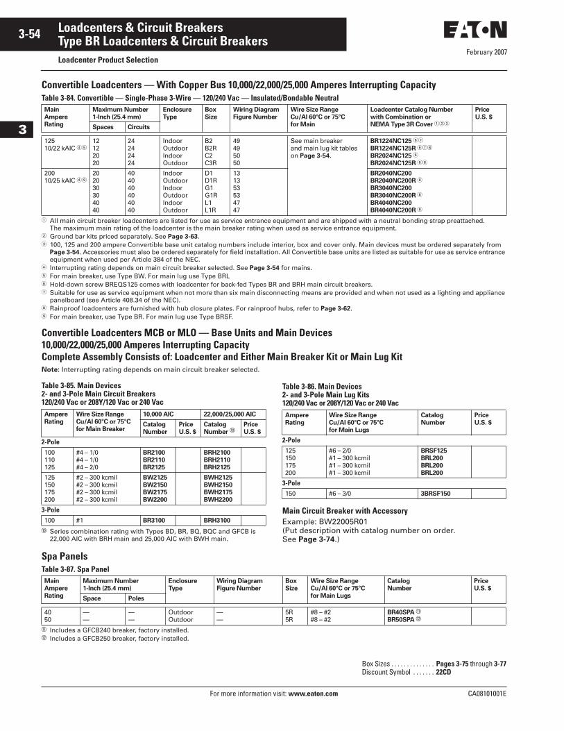
February 2007
3-54
For more information visit: www.eaton.com CA08101001E
Loadcenters & Circuit Breakers
3
Type BR Loadcenters & Circuit BreakersLoadcenter Product Selection
Convertible Loadcenters — With Copper Bus 10,000/22,000/25,000 Amperes Interrupting CapacityTable 3-84. Convertible — Single-Phase 3-Wire — 120/240 Vac — Insulated/Bondable Neutral
� All main circuit breaker loadcenters are listed for use as service entrance equipment and are shipped with a neutral bonding strap preattached. The maximum main rating of the loadcenter is the main breaker rating when used as service entrance equipment.
� Ground bar kits priced separately. See Page 3-63.� 100, 125 and 200 ampere Convertible base unit catalog numbers include interior, box and cover only. Main devices must be ordered separately from
Page 3-54. Accessories must also be ordered separately for field installation. All Convertible base units are listed as suitable for use as service entrance equipment when used per Article 384 of the NEC.
� Interrupting rating depends on main circuit breaker selected. See Page 3-54 for mains.� For main breaker, use Type BW. For main lug use Type BRL� Hold-down screw BREQS125 comes with loadcenter for back-fed Types BR and BRH main circuit breakers.� Suitable for use as service equipment when not more than six main disconnecting means are provided and when not used as a lighting and appliance
panelboard (see Article 408.34 of the NEC). Rainproof loadcenters are furnished with hub closure plates. For rainproof hubs, refer to Page 3-62. For main breaker, use Type BR. For main lug use Type BRSF.
Convertible Loadcenters MCB or MLO — Base Units and Main Devices10,000/22,000/25,000 Amperes Interrupting CapacityComplete Assembly Consists of: Loadcenter and Either Main Breaker Kit or Main Lug KitNote: Interrupting rating depends on main circuit breaker selected.
� Series combination rating with Types BD, BR, BQ, BQC and GFCB is 22,000 AIC with BRH main and 25,000 AIC with BWH main.
Main Circuit Breaker with AccessoryExample: BW22005R01(Put description with catalog number on order. See Page 3-74.)
Spa PanelsTable 3-87. Spa Panel
� Includes a GFCB240 breaker, factory installed.� Includes a GFCB250 breaker, factory installed.
Main
Ampere
Rating
Maximum Number
1-Inch (25.4 mm)
Enclosure
Type
Box
Size
Wiring Diagram
Figure Number
Wire Size Range
Cu/Al 60°C or 75°C
for Main
Loadcenter Catalog Number
with Combination or
NEMA Type 3R Cover ���
Price
U.S. $
Spaces Circuits
12510/22 kAIC ��
12122020
24242424
IndoorOutdoorIndoorOutdoor
B2B2RC2C3R
49495050
See main breaker and main lug kit tables on Page 3-54.
BR1224NC125 ��
BR1224NC125R ��
BR2024NC125 �
BR2024NC125R �
20010/25 kAIC �
202030304040
404040404040
IndoorOutdoorIndoorOutdoorIndoorOutdoor
D1D1RG1G1RL1L1R
131353534747
BR2040NC200
BR2040NC200R
BR3040NC200
BR3040NC200R
BR4040NC200
BR4040NC200R
Table 3-85. Main Devices2- and 3-Pole Main Circuit Breakers120/240 Vac or 208Y/120 Vac or 240 VacAmpere
Rating
Wire Size Range
Cu/Al 60°C or 75°C
for Main Breaker
10,000 AIC 22,000/25,000 AIC
Catalog
Number
Price
U.S. $
Catalog
Number �Price
U.S. $
2-Pole100110125
#4 – 1/0#4 – 1/0#4 – 2/0
BR2100
BR2110
BR2125
BRH2100
BRH2110
BRH2125
125150175200
#2 – 300 kcmil#2 – 300 kcmil#2 – 300 kcmil#2 – 300 kcmil
BW2125
BW2150
BW2175
BW2200
BWH2125
BWH2150
BWH2175
BWH2200
3-Pole100 #1 BR3100 BRH3100
Table 3-86. Main Devices2- and 3-Pole Main Lug Kits120/240 Vac or 208Y/120 Vac or 240 VacAmpere
Rating
Wire Size Range
Cu/Al 60°C or 75°C
for Main Lugs
Catalog
Number
Price
U.S. $
2-Pole125150175200
#6 – 2/0#1 – 300 kcmil#1 – 300 kcmil#1 – 300 kcmil
BRSF125
BRL200
BRL200
BRL200
3-Pole150 #6 – 3/0 3BRSF150
Main
Ampere
Rating
Maximum Number
1-Inch (25.4 mm)
Enclosure
Type
Wiring Diagram
Figure Number
Box
Size
Wire Size Range
Cu/Al 60°C or 75°C
for Main Lugs
Catalog
Number
Price
U.S. $
Space Poles
4050
——
——
OutdoorOutdoor
——
5R5R
#8 – #2#8 – #2
BR40SPA �
BR50SPA �
Box Sizes . . . . . . . . . . . . . . Pages 3-75 through 3-77Discount Symbol . . . . . . . 22CD
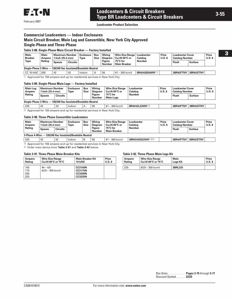
February 2007
CA08101001E For more information visit: www.eaton.com
3-55Loadcenters & Circuit Breakers
3
Type BR Loadcenters & Circuit BreakersLoadcenter Product Selection
Commercial Loadcenters — Indoor EnclosuresMain Circuit Breaker, Main Lug and Convertible, New York City ApprovedSingle-Phase and Three-PhaseTable 3-88. Single-Phase Main Circuit Breaker — Factory Installed
� Approved for 150 ampere and up for residential services in New York City.
Table 3-89. Single-Phase Main Lugs — Factory Installed
� Approved for 150 ampere and up for residential services in New York City.
Table 3-90. Three-Phase Convertible Loadcenters
� Approved for 150 ampere and up for residential services in New York City.� Order main device from Table 3-91 and Table 3-92 below.
Table 3-91. Three-Phase Main Breaker Kits Table 3-92. Three-Phase Main Lugs Kit
Main
Breaker
Type
Main
Ampere
Rating
Maximum Number
1-Inch (25.4 mm)
Enclosure
Type
Box
Size
Wiring
Diagram
Figure
Number
Wire Size Range
Cu/Al 60°C or
75°C for
Main Breaker
Loadcenter
Catalog
Number
Price
U.S. $
Loadcenter Cover
Catalog Number
Price
U.S. $
Spaces Circuits Flush Surface
Single-Phase 3-Wire — 120/240 Vac Insulated/Bondable NeutralCC 10 kAIC 200 42 42 Indoor A 56 #1 – 300 kcmil BR4242B200NY � 3BR42FTNY 3BR42STNY
Main Lug
Ampere
Rating
Maximum Number
1-Inch (25.4 mm)
Enclosure
Type
Box
Size
Wiring
Diagram
Figure
Number
Wire Size Range
Cu/Al 60°C or
75°C for
Main Lugs
Loadcenter
Catalog
Number
Price
U.S. $
Loadcenter Cover
Catalog Number
Price
U.S. $
Spaces Circuits Flush Surface
Single-Phase 3-Wire — 120/240 Vac Insulated/Bondable Neutral225 42 42 Indoor A 55 #1 – 300 kcmil BR4242L225NY � 3BR42FTNY 3BR42STNY
Main
Ampere
Rating
Maximum Number
1-Inch (25.4 mm)
Enclosure
Type
Box
Size
Wiring
Diagram
Figure
Number
Wire Size Range
Cu/Al 60°C or
75°C for
Main Breaker
Loadcenter
Catalog
Number
Price
U.S. $
Loadcenter Cover
Catalog Number
Price
U.S. $
Spaces Circuits Flush Surface
3-Phase 4-Wire — 120/240 Vac Insulated/Bondable Neutral225 42 42 Indoor B 56 #1 – 300 kcmil 3BR4242N225NY �� 3BR42FTNY 3BR42STNY
Ampere
Rating
Wire Size Range
Cu/Al 60°C or 75°C
Main Breaker Kit
10 kAIC
Price
U.S. $
150175200225
#4 – 4/0#2/0 – 300 kcmil
CC3150N
CC3175N
CC3200N
CC3225N
Ampere
Rating
Wire Size Range
Cu/Al 60°C or 75°C
Main
Lugs Kit
Price
U.S. $
225 #2/0 – 300 kcmil 3BRL225
Box Sizes . . . . . . . . . . . . . Pages 3-75 through 3-77Discount Symbol . . . . . . . 22CD
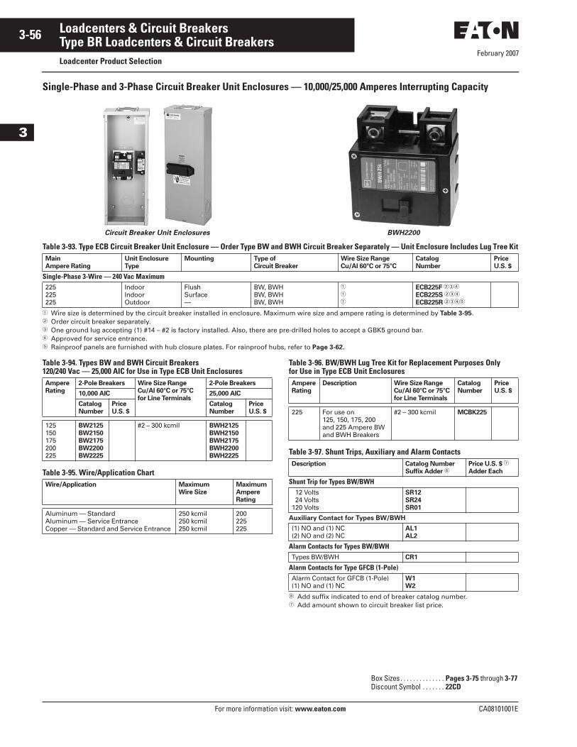
February 2007
3-56
For more information visit: www.eaton.com CA08101001E
Loadcenters & Circuit Breakers
3
Type BR Loadcenters & Circuit BreakersLoadcenter Product Selection
Single-Phase and 3-Phase Circuit Breaker Unit Enclosures — 10,000/25,000 Amperes Interrupting Capacity
Circuit Breaker Unit Enclosures BWH2200
Table 3-93. Type ECB Circuit Breaker Unit Enclosure — Order Type BW and BWH Circuit Breaker Separately — Unit Enclosure Includes Lug Tree Kit
� Wire size is determined by the circuit breaker installed in enclosure. Maximum wire size and ampere rating is determined by Table 3-95.� Order circuit breaker separately.� One ground lug accepting (1) #14 – #2 is factory installed. Also, there are pre-drilled holes to accept a GBK5 ground bar.� Approved for service entrance.� Rainproof panels are furnished with hub closure plates. For rainproof hubs, refer to Page 3-62.
Table 3-94. Types BW and BWH Circuit Breakers120/240 Vac — 25,000 AIC for Use in Type ECB Unit Enclosures
Table 3-95. Wire/Application Chart
Table 3-96. BW/BWH Lug Tree Kit for Replacement Purposes Onlyfor Use in Type ECB Unit Enclosures
Table 3-97. Shunt Trips, Auxiliary and Alarm Contacts
� Add suffix indicated to end of breaker catalog number.� Add amount shown to circuit breaker list price.
Main
Ampere Rating
Unit Enclosure
Type
Mounting Type of
Circuit Breaker
Wire Size Range
Cu/Al 60°C or 75°C
Catalog
Number
Price
U.S. $
Single-Phase 3-Wire — 240 Vac Maximum225225225
IndoorIndoorOutdoor
FlushSurface—
BW, BWHBW, BWHBW, BWH
�
�
�
ECB225F ���
ECB225S ���
ECB225R ����
Ampere
Rating
2-Pole Breakers Wire Size Range
Cu/Al 60°C or 75°C
for Line Terminals
2-Pole Breakers
10,000 AIC 25,000 AIC
Catalog
Number
Price
U.S. $
Catalog
Number
Price
U.S. $
125150175200225
BW2125
BW2150
BW2175
BW2200
BW2225
#2 – 300 kcmil BWH2125
BWH2150
BWH2175
BWH2200
BWH2225
Wire/Application Maximum
Wire Size
Maximum
Ampere
Rating
Aluminum — StandardAluminum — Service EntranceCopper — Standard and Service Entrance
250 kcmil250 kcmil250 kcmil
200225225
Ampere
Rating
Description Wire Size Range
Cu/Al 60°C or 75°C
for Line Terminals
Catalog
Number
Price
U.S. $
225 For use on125, 150, 175, 200and 225 Ampere BWand BWH Breakers
#2 – 300 kcmil MCBK225
Description Catalog Number
Suffix Adder �Price U.S. $ �
Adder Each
Shunt Trip for Types BW/BWH 12 Volts 24 Volts120 Volts
SR12
SR24
SR01
Auxiliary Contact for Types BW/BWH
(1) NO and (1) NC(2) NO and (2) NC
AL1
AL2
Alarm Contacts for Types BW/BWHTypes BW/BWH CR1
Alarm Contacts for Type GFCB (1-Pole)Alarm Contact for GFCB (1-Pole)(1) NO and (1) NC
W1
W2
Box Sizes . . . . . . . . . . . . . . Pages 3-75 through 3-77Discount Symbol . . . . . . . 22CD
February 2007
CA08101001E For more information visit: www.eaton.com
3-57Loadcenters & Circuit Breakers
3
Type BR Loadcenters & Circuit BreakersLoadcenter Product Selection
Single-Phase and 3-Phase Circuit Breaker Unit Enclosures — 10,000/25,000 Amperes Interrupting CapacityTable 3-98. Type ECC Circuit Breaker Unit Enclosure — Order Type CC Circuit Breaker Separately
� Order circuit breaker separately.� One ground lug accepting (1) #14 – #2 is factory installed. Also, there are pre-drilled holes to accept a GBK5 ground bar.� Approved for service entrance.� Rainproof panels are furnished with hub closures plates. For rainproof hubs, refer to Page 3-62.� Wire size is determined by the circuit breaker installed in enclosure. Maximum wire size and ampere rating is determined by Table 3-95.
Table 3-99. Type CC Circuit Breaker 240 Vac — 10 kAIC for Use in Type ECC Unit Enclosures Table 3-100. Wire/Application Chart
Table 3-101. Shunt Trips and Auxiliary Contacts
� Add suffix indicated to end of breaker catalog number.
Main Ampere
Rating
Unit Enclosure
Type
Type of
Mounting
Type of
Circuit Breaker
Wire Size Range
Cu/Al 60°C or 75°C
Catalog
Number
Price
U.S. $
Single-Phase 3-Wire — 240 Vac Maximum225225225
IndoorIndoorOutdoor
FlushSurface—
CCCCCC
�
�
�
ECC225F ���
ECC225S ���
ECC225R ����
Ampere
Rating
Wire Size
Range
Cu/Al 60°C
or 75°C for
Line Terminals
Type CC
10 kAIC
Catalog
Number
Price
U.S. $
2-Pole100125150
#4 – 4/0 CC2100
CC2125
CC2150
175200225
#2/0 – 300 kcmil CC2175
CC2200
CC2225
3-Pole100125150
#4 – 4/0 CC3100
CC3125
CC3150
175200225
#2/0 – 300 kcmil CC3175
CC3200
CC3225
Wire/Application Maximum
Wire Size
Maximum
Ampere Rating
Aluminum — StandardAluminum — Service EntranceCopper — Standard and Service Entrance
250 kcmil250 kcmil250 kcmil
200225225
Description Catalog Number
Suffix Adder �Price U.S. $
Adder EachType Volts
Shunt TripCCCC
12 dc 24 dc
SR12
SR24
CCCCCC
120 ac208 ac240 ac
SR01
SR08
SR02
Auxiliary ContactCC (1) NO and (1) NC — AL1
Box Sizes . . . . . . . . . . . . . Pages 3-75 through 3-77Discount Symbol . . . . . . . 22CD
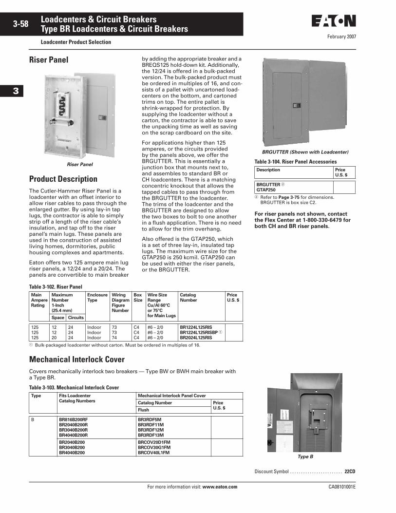
February 2007
3-58
For more information visit: www.eaton.com CA08101001E
Loadcenters & Circuit Breakers
3
Type BR Loadcenters & Circuit BreakersLoadcenter Product Selection
Riser Panel
Riser Panel
Product DescriptionThe Cutler-Hammer Riser Panel is a loadcenter with an offset interior to allow riser cables to pass through the enlarged gutter. By using lay-in tap lugs, the contractor is able to simply strip off a length of the riser cable’s insulation, and tap off to the riser panel’s main lugs. These panels are used in the construction of assisted living homes, dormitories, public housing complexes and apartments.
Eaton offers two 125 ampere main lug riser panels, a 12/24 and a 20/24. The panels are convertible to main breaker
by adding the appropriate breaker and a BREQS125 hold-down kit. Additionally, the 12/24 is offered in a bulk-packed version. The bulk-packed product must be ordered in multiples of 16, and con-sists of a pallet with uncartoned load-centers on the bottom, and cartoned trims on top. The entire pallet is shrink-wrapped for protection. By supplying the loadcenter without a carton, the contractor is able to save the unpacking time as well as saving on the scrap cardboard on the site.
For applications higher than 125 amperes, or the circuits provided by the panels above, we offer the BRGUTTER. This is essentially a junction box that mounts next to, and assembles to standard BR or CH loadcenters. There is a matching concentric knockout that allows the tapped cables to pass through from the BRGUTTER to the loadcenter. The trims of the loadcenter and the BRGUTTER are designed to allow the two boxes to bolt to one another in a flush application. There is no need to allow for the trim overhang.
Also offered is the GTAP250, which is a set of three lay-in, insulated tap lugs. The maximum wire size for the GTAP250 is 250 kcmil. GTAP250 can be used with either the riser panels, or the BRGUTTER.
Table 3-102. Riser Panel
� Bulk-packaged loadcenter without carton. Must be ordered in multiples of 16.
Mechanical Interlock CoverCovers mechanically interlock two breakers — Type BW or BWH main breaker with a Type BR.
Table 3-103. Mechanical Interlock Cover
Main
Ampere
Rating
Maximum
Number
1-Inch
(25.4 mm)
Enclosure
Type
Wiring
Diagram
Figure
Number
Box
Size Wire Size
Range
Cu/Al 60°C
or 75°C
for Main Lugs
Catalog
Number
Price
U.S. $
Space Circuits
125125125
121220
242424
IndoorIndoorIndoor
737374
C4C4C4
#6 – 2/0#6 – 2/0#6 – 2/0
BR1224L125RIS
BR1224L125RISBP �
BR2024L125RIS
Type Fits Loadcenter
Catalog Numbers
Mechanical Interlock Panel Cover
Catalog Number Price
U.S. $Flush
B BR816B200RF
BR2040B200R
BR3040B200R
BR4040B200R
BR3RDF5M
BR3RDF11M
BR3RDF12M
BR3RDF13M
BR2040B200
BR3040B200
BR4040B200
BRCOV20D1FM
BRCOV30G1FM
BRCOV40L1FM
BRGUTTER (Shown with Loadcenter)
Table 3-104. Riser Panel Accessories
� Refer to Page 3-75 for dimensions. BRGUTTER is box size C2.
For riser panels not shown, contact the Flex Center at 1-800-330-6479 for both CH and BR riser panels.
Type B
Description Price
U.S. $
BRGUTTER �
GTAP250
Discount Symbol . . . . . . . . . . . . . . . . . . . . . . . . 22CD
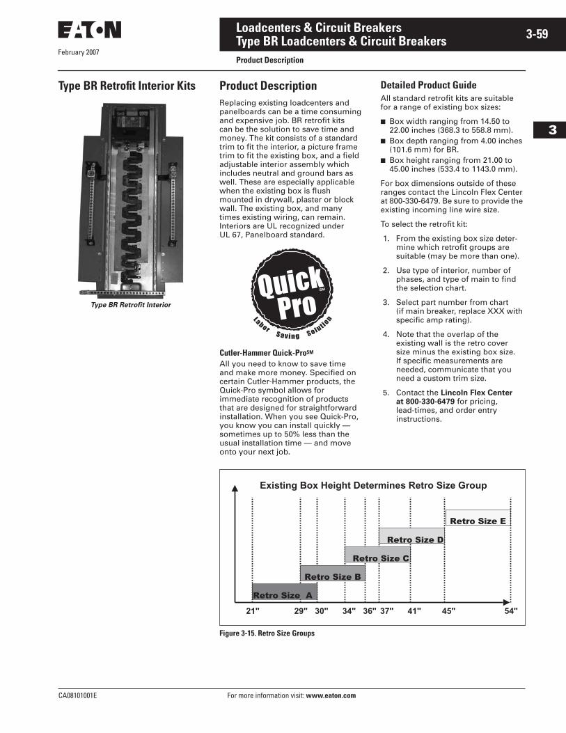
February 2007
CA08101001E For more information visit: www.eaton.com
3-59Loadcenters & Circuit Breakers
3
Type BR Loadcenters & Circuit BreakersProduct Description
Type BR Retrofit Interior Kits
Type BR Retrofit Interior
Product DescriptionReplacing existing loadcenters and panelboards can be a time consuming and expensive job. BR retrofit kits can be the solution to save time and money. The kit consists of a standard trim to fit the interior, a picture frame trim to fit the existing box, and a field adjustable interior assembly which includes neutral and ground bars as well. These are especially applicable when the existing box is flush mounted in drywall, plaster or block wall. The existing box, and many times existing wiring, can remain. Interiors are UL recognized under UL 67, Panelboard standard.
Detailed Product GuideAll standard retrofit kits are suitable for a range of existing box sizes:
■ Box width ranging from 14.50 to 22.00 inches (368.3 to 558.8 mm).
■ Box depth ranging from 4.00 inches (101.6 mm) for BR.
■ Box height ranging from 21.00 to 45.00 inches (533.4 to 1143.0 mm).
For box dimensions outside of these ranges contact the Lincoln Flex Center at 800-330-6479. Be sure to provide the existing incoming line wire size.
To select the retrofit kit:
1. From the existing box size deter-mine which retrofit groups are suitable (may be more than one).
2. Use type of interior, number of phases, and type of main to find the selection chart.
3. Select part number from chart (if main breaker, replace XXX with specific amp rating).
4. Note that the overlap of the existing wall is the retro cover size minus the existing box size.If specific measurements are needed, communicate that you need a custom trim size.
5. Contact the Lincoln Flex Center at 800-330-6479 for pricing, lead-times, and order entry instructions.
Figure 3-15. Retro Size Groups
Cutler-Hammer Quick-ProSM
All you need to know to save time and make more money. Specified on certain Cutler-Hammer products, the Quick-Pro symbol allows for immediate recognition of products that are designed for straightforward installation. When you see Quick-Pro, you know you can install quickly — sometimes up to 50% less than the usual installation time — and move onto your next job.
Existing Box Height Determines Retro Size Group
21" 29" 30" 34" 36" 37" 41" 45" 54"
Retro Size A
Retro Size B
Retro Size C
Retro Size D
Retro Size E
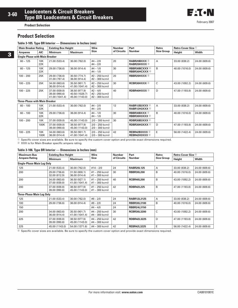
February 2007
3-60
For more information visit: www.eaton.com CA08101001E
Loadcenters & Circuit Breakers
3
Type BR Loadcenters & Circuit BreakersProduct Selection
Product SelectionTable 3-105. Type BR Interior — Dimensions in Inches (mm)
� Specific cover sizes are available. Be sure to specify the custom cover option and provide exact dimensions required.� XXX is for Main Breaker specific ampere rating.
Table 3-106. Type BR Interior — Dimensions in Inches (mm)
� Specific cover sizes are available. Be sure to specify the custom cover option and provide exact dimensions required.
Main Breaker Rating Existing Box Height Wire
Size
Number
of Circuits
Part
Number
Retro
Size Group
Retro Cover Size �
Amperes AIC Minimum Maximum Height Width
Single-Phase with Main Breaker 60 – 125 10K
22K21.00 (533.4) 30.00 (762.0) #4 – 2/0
#4 – 2/020 RABR20BXXX �
RABR20HXXX �A 33.00 (838.2) 24.00 (609.6)
60 – 125 10K22K
29.00 (736.6) 36.00 (914.4) #4 – 1/0#4 – 1/0
30 RBBR30BCXXX �
RBBR30HCXXX �B 40.00 (1016.0) 24.00 (609.6)
100 – 200 25K 29.00 (736.6)31.00 (787.4)
30.50 (774.7)36.00 (914.4)
#2 – 250 kcmil#2 – 300 kcmil
20 RBBR20HXXX �
100 – 225 25K 34.00 (863.6)36.00 (914.4)
35.50 (901.7)41.00 (1041.4)
#2 – 250 kcmil#2 – 300 kcmil
30 RCBR30HXXX � C 43.00 (1092.2) 24.00 (609.6)
100 – 225 25K 37.00 (939.8)39.00 (990.6)41.00 (1041.4)
38.50 (977.9)40.50 (1028.7)45.00 (1143.0)
#2 – 4/0#2 – 250 kcmil#2 – 300 kcmil
40 RDBR40HXXX � D 47.00 (1193.8) 24.00 (609.6)
Three-Phase with Main Breaker 60 – 100 10K
22K21.00 (533.4) 30.00 (762.0) #4 – 2/0
#4 – 2/012 RABR12B3XXX �
RABR12H3XXX �A 33.00 (838.2) 24.00 (609.6)
60 – 100 10K22K
29.00 (736.6) 36.00 (914.4) #4 – 1/0#4 – 1/0
30 RBBR30BXXX �
RBBR30H3XXX �B 40.00 (1016.0) 24.00 (609.6)
100 – 200 10K 37.00 (939.8) 45.00 (1143.0) 2/0 – 300 kcmil 30 RDBR30B3XXX �
100K 37.00 (939.8)39.00 (990.6)
38.50 (977.9)45.00 (1143.0)
2/0 – 250 kcmil2/0 – 300 kcmil
RDBR30H3XXX � D 47.00 (1193.8) 24.00 (609.6)
100 – 225 10K100K
34.00 (863.6)36.00 (914.4)
35.50 (901.7)41.00 (1041.4)
2/0 – 250 kcmil2/0 – 300 kcmil
42 REBR42B3XXX �
REBR42H3XXX �E 56.00 (1422.4) 24.00 (609.6)
Maximum Bus
Ampere Rating
Existing Box Height Wire
Size
Number
of Circuits
Part
Number
Retro
Size Group
Retro Cover Size �
Minimum Maximum Height Width
Single-Phase Main Lug Only125 21.00 (533.4) 30.00 (762.0) #14 – 2/0 24 RABR20L125 A 33.00 (838.2) 24.00 (609.6)
200 29.00 (736.6)32.00 (812.9)
31.50 (800.1)36.00 (914.4)
#1 – 250 kcmil#1 – 300 kcmil
30 RBBR30L200 B 40.00 (1016.0) 24.00 (609.6)
200 34.00 (863.6)37.00 (939.8)
36.50 (927.1)41.00 (1041.4)
#1 – 250 kcmil#1 – 300 kcmil
40 RCBR40L200 B 43.00 (1092.2) 24.00 (609.6)
200 37.00 (939.8)39.00 (990.6)
38.50 (977.9)45.00 (1143.0)
#1 – 250 kcmil#1 – 300 kcmil
42 RDBR42L225 B 47.00 (1193.8) 24.00 (609.6)
Three-Phase Main Lug Only125 21.00 (533.4) 30.00 (762.0) #8 – 2/0 24 RABR12L3125 A 33.00 (838.2) 24.00 (609.6)
100 29.00 (736.6) 36.00 (914.4) #8 – 2/0 24 RBBR30L3100 B 40.00 (1016.0) 24.00 (609.6)
150 #4 – 4/0 24 RBBR24L3150
200 34.00 (863.6)36.00 (914.4)
35.50 (901.7)41.00 (1041.4)
#4 – 250 kcmil#4 – 300 kcmil
30 RCBR30L3200 C 43.00 (1092.2) 24.00 (609.6)
225 37.00 (939.8)39.00 (990.6)
38.50 (977.9)45.00 (1143.0)
#4 – 250 kcmil#4 – 300 kcmil
42 RDBR42L3225 D 47.00 (1193.8) 24.00 (609.6)
225 45.00 (1143.0) 54.00 (1371.6) #4 – 300 kcmil 42 REBR42L3225 E 56.00 (1422.4) 24.00 (609.6)
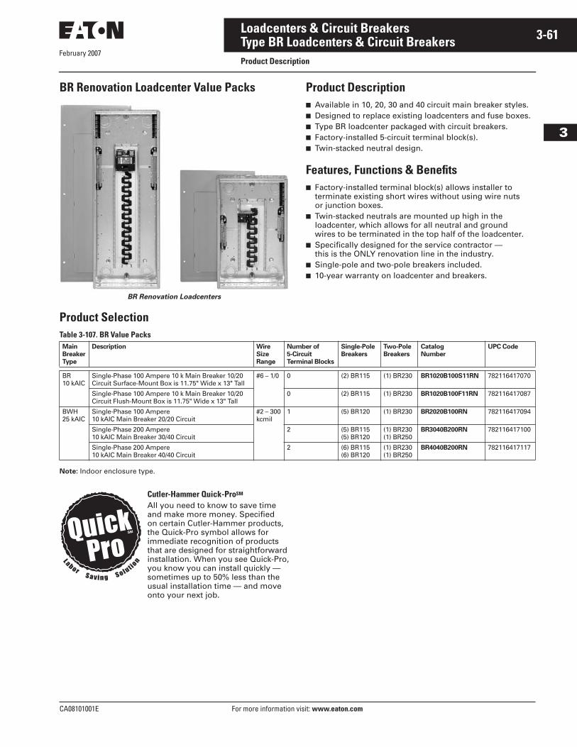
February 2007
CA08101001E For more information visit: www.eaton.com
3-61Loadcenters & Circuit Breakers
3
Type BR Loadcenters & Circuit BreakersProduct Description
BR Renovation Loadcenter Value Packs
BR Renovation Loadcenters
Product Description■ Available in 10, 20, 30 and 40 circuit main breaker styles.■ Designed to replace existing loadcenters and fuse boxes.■ Type BR loadcenter packaged with circuit breakers.■ Factory-installed 5-circuit terminal block(s).■ Twin-stacked neutral design.
Features, Functions & Benefits■ Factory-installed terminal block(s) allows installer to
terminate existing short wires without using wire nuts or junction boxes.
■ Twin-stacked neutrals are mounted up high in the loadcenter, which allows for all neutral and ground wires to be terminated in the top half of the loadcenter.
■ Specifically designed for the service contractor — this is the ONLY renovation line in the industry.
■ Single-pole and two-pole breakers included.■ 10-year warranty on loadcenter and breakers.
Product SelectionTable 3-107. BR Value Packs
Note: Indoor enclosure type.
Main
Breaker
Type
Description Wire
Size
Range
Number of
5-Circuit
Terminal Blocks
Single-Pole
Breakers
Two-Pole
Breakers
Catalog
Number
UPC Code
BR10 kAIC
Single-Phase 100 Ampere 10 k Main Breaker 10/20Circuit Surface-Mount Box is 11.75" Wide x 13" Tall
#6 – 1/0 0 (2) BR115 (1) BR230 BR1020B100S11RN 782116417070
Single-Phase 100 Ampere 10 k Main Breaker 10/20Circuit Flush-Mount Box is 11.75" Wide x 13" Tall
0 (2) BR115 (1) BR230 BR1020B100F11RN 782116417087
BWH25 kAIC
Single-Phase 100 Ampere 10 kAIC Main Breaker 20/20 Circuit
#2 – 300kcmil
1 (5) BR120 (1) BR230 BR2020B100RN 782116417094
Single-Phase 200 Ampere10 kAIC Main Breaker 30/40 Circuit
2 (5) BR115 (5) BR120
(1) BR230(1) BR250
BR3040B200RN 782116417100
Single-Phase 200 Ampere10 kAIC Main Breaker 40/40 Circuit
2 (6) BR115 (6) BR120
(1) BR230 (1) BR250
BR4040B200RN 782116417117
Cutler-Hammer Quick-ProSM
All you need to know to save time and make more money. Specified on certain Cutler-Hammer products, the Quick-Pro symbol allows for immediate recognition of products that are designed for straightforward installation. When you see Quick-Pro,you know you can install quickly — sometimes up to 50% less than the usual installation time — and move onto your next job.
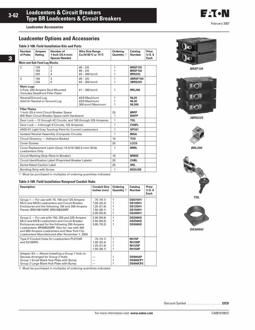
February 2007
3-62
For more information visit: www.eaton.com CA08101001E
Loadcenters & Circuit Breakers
3
Type BR Loadcenters & Circuit BreakersLoadcenter Accessories
Loadcenter Options and AccessoriesTable 3-108. Field Installation Kits and Parts
� Must be purchased in multiples of ordering quantities indicated.
Table 3-109. Field Installation Rainproof Conduit Hubs
� Must be purchased in multiples of ordering quantities indicated.
Number
of Poles
Ampere
Rating
Number of
1-Inch (25.4 mm)
Spaces Needed
Wire Size Range
Cu/Al 60°C or 75°C
Ordering
Quantity �Catalog
Number
Price
U.S. $
Each
Main and Sub-Feed Lug Blocks2 125
150225
224
#8 – 2/0#8 – 2/0#2 – 300 kcmil
111
BRSF125
BRSF150
BRS225
3 150225
36
#8 – 2/0#2 – 300 kcmil
11
3BRSF150
3BRS225
Main Lugs
2-Pole, 200 Ampere Stud Mounted (Includes Deadfront Filler Plate)
#1 – 300 kcmil 1 BRL200
Neutral/Ground LugAdd-On Neutral or Ground Lug
#2/0 Maximum#3/0 Maximum300 kcmil Maximum
111
NL20
NL30
NL300
Filler Plates
1-Inch (25.4 mm) Circuit Breaker SpaceBW Main Circuit Breaker Space (with Hardware)
251
BRFP
BWFP
Door Lock —12 through 42 Circuits, and 100 through 225 Amperes 1 TDL
Door Lock — 4 through 8 Circuits, 125 Amperes 1 CH9FL
ANSI-61 Light Gray Touchup Paint for Current Loadcenters 1 SPC61
Isolated Neutral Assembly (Computer Circuits) 1 BINA
Circuit Directory — Adhesive Backed 10 TCD
Cover Screws 25 LCCS
Cover Replacement Latch (Gray) 14-5/16 (363.5 mm) Wide Loadcenters Only
1 BRRL
Circuit Marking Strip (Next to Breaker) 10 BRMS
Circuit Identification Label (Preprinted Breaker Labels) 25 CHBL
Series Rated Caution Label 25 SRL
Bonding Strip with Screw 1 BSSUSE
Description Conduit Size
Inches (mm)
Ordering
Quantity �Catalog
Number
Price
U.S. $
Each
Group 1 — For use with 70, 100 and 125 Ampere MLO and MCB Loadcenters and Circuit Breaker Enclosures and the following 150 and 200 Ampere Panels: BR816B150RF, BR816B200RF
.75 (19.1)1.00 (25.4)1.25 (31.8)1.50 (38.1)2.00 (50.8)
11111
DS075H1
DS100H1
DS125H1
DS150H1
DS200H1
Group 2 — For use with 150, 200 and 225 Ampere MLO and MCB Loadcenters and Circuit Breaker Enclosures except for the following 200 AmpereLoadcenters: BR48B200RF. Also for use with 400 and 600 Ampere Loadcenters and New York City Loadcenters Manufactured after November 1, 2005
2.00 (50.8)2.50 (63.5)3.00 (76.2)
111
DS200H2
DS250H2
DS300H2
Type H Conduit Hubs for Loadcenters PL0724R and S3100RN
.75 (19.1)1.00 (25.4)1.25 (31.8)1.50 (38.1)
1111
RH75P
RH100P
RH125P
RH150P
Adapter Kit — Allows Installing a Group 1 Hub onDevices Arranged for Group 2 HubsGroup 1 Small Blank Hub Plate with BumpGroup 2 Large Blank Hub Plate with Bump
———
111
DS900AP
DS900CP1
DS900CP2
BRSF125
3BRS225
BRL200
TDL
DS300H2
Discount Symbol . . . . . . . . . . . . . . . . . . . . . . . . 22CD
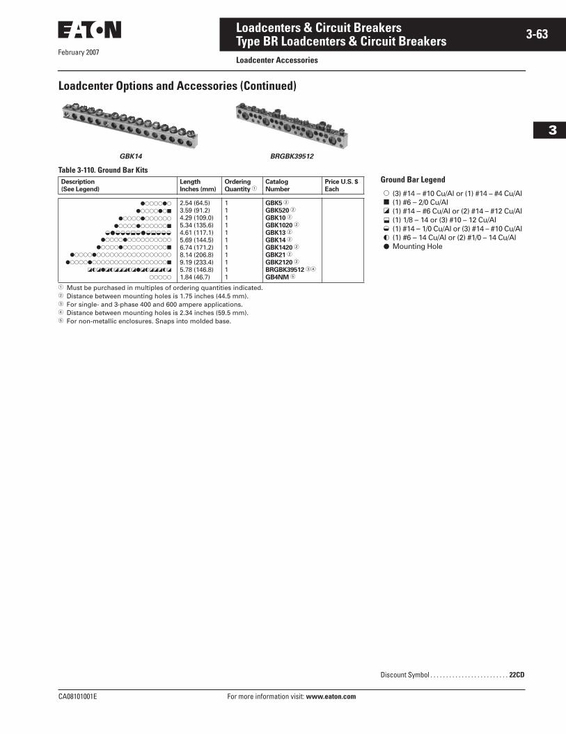
CA08101001E For more information visit: www.eaton.com
3-63Loadcenters & Circuit Breakers
February 2007
3
Type BR Loadcenters & Circuit BreakersLoadcenter Accessories
Loadcenter Options and Accessories (Continued)
GBK14 BRGBK39512
Table 3-110. Ground Bar Kits
� Must be purchased in multiples of ordering quantities indicated.� Distance between mounting holes is 1.75 inches (44.5 mm).� For single- and 3-phase 400 and 600 ampere applications.� Distance between mounting holes is 2.34 inches (59.5 mm).� For non-metallic enclosures. Snaps into molded base.
Description
(See Legend)
Length
Inches (mm)
Ordering
Quantity �Catalog
Number
Price U.S. $
Each
�������
��������
������������
�������������
����������������
�����������������
�����������������������
������������������������
�������������������
�����
2.54 (64.5)3.59 (91.2)4.29 (109.0)5.34 (135.6)4.61 (117.1)5.69 (144.5)6.74 (171.2)8.14 (206.8)9.19 (233.4)5.78 (146.8)1.84 (46.7)
11111111111
GBK5 �
GBK520 �
GBK10 �
GBK1020 �
GBK13 �
GBK14 �
GBK1420 �
GBK21 �
GBK2120 �
BRGBK39512 ��
GB4NM �
� � � � � � � � � � � � �
Ground Bar Legend
Discount Symbol . . . . . . . . . . . . . . . . . . . . . . . . . 22CD
�
�
�
�
�
(3) #14 – #10 Cu/Al or (1) #14 – #4 Cu/Al(1) #6 – 2/0 Cu/Al(1) #14 – #6 Cu/Al or (2) #14 – #12 Cu/Al(1) 1/8 – 14 or (3) #10 – 12 Cu/Al(1) #14 – 1/0 Cu/Al or (3) #14 – #10 Cu/Al(1) #6 – 14 Cu/Al or (2) #1/0 – 14 Cu/AlMounting Hole
��
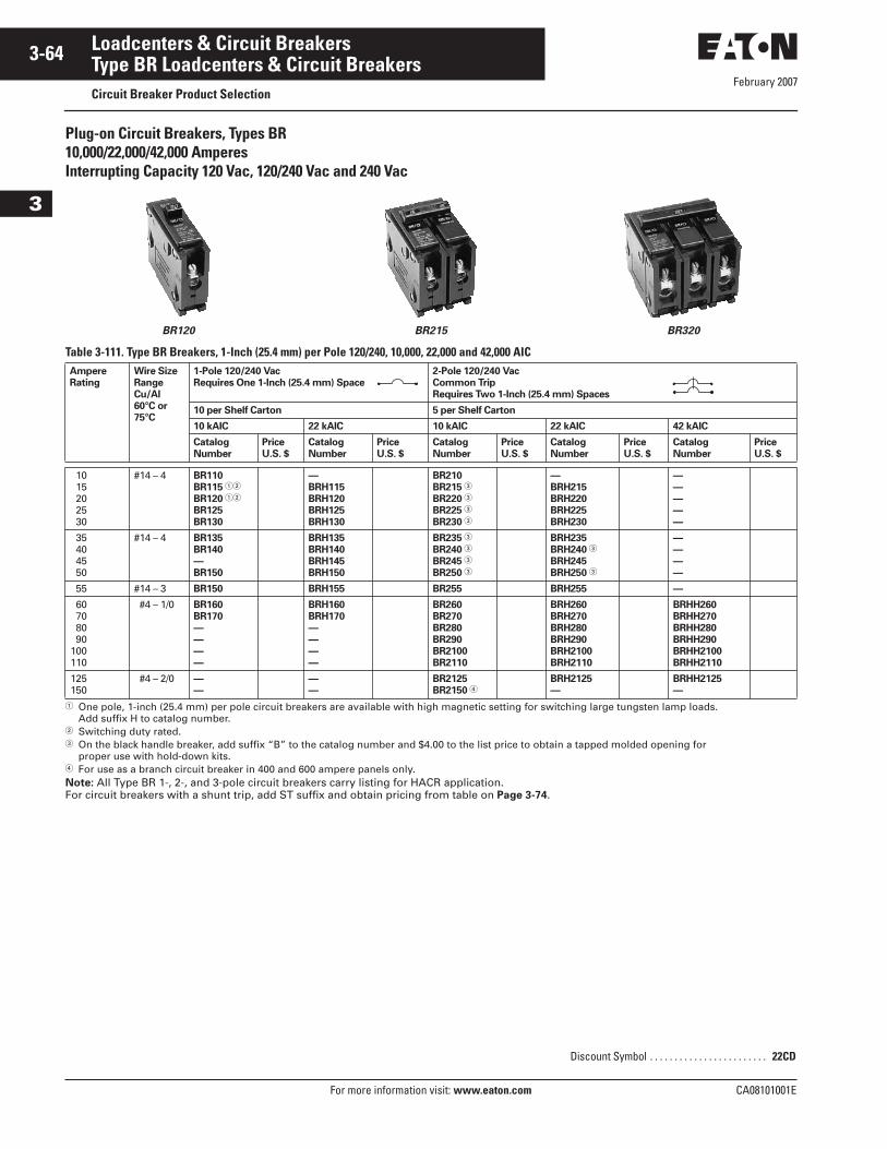
February 2007
3-64
For more information visit: www.eaton.com CA08101001E
Loadcenters & Circuit Breakers
3
Type BR Loadcenters & Circuit BreakersCircuit Breaker Product Selection
Plug-on Circuit Breakers, Types BR10,000/22,000/42,000 Amperes Interrupting Capacity 120 Vac, 120/240 Vac and 240 Vac
BR120 BR215 BR320
Table 3-111. Type BR Breakers, 1-Inch (25.4 mm) per Pole 120/240, 10,000, 22,000 and 42,000 AIC
� One pole, 1-inch (25.4 mm) per pole circuit breakers are available with high magnetic setting for switching large tungsten lamp loads. Add suffix H to catalog number.
� Switching duty rated.� On the black handle breaker, add suffix “B” to the catalog number and $4.00 to the list price to obtain a tapped molded opening for
proper use with hold-down kits.� For use as a branch circuit breaker in 400 and 600 ampere panels only.Note: All Type BR 1-, 2-, and 3-pole circuit breakers carry listing for HACR application. For circuit breakers with a shunt trip, add ST suffix and obtain pricing from table on Page 3-74.
Ampere
Rating
Wire Size
Range
Cu/Al
60°C or
75°C
1-Pole 120/240 Vac
Requires One 1-Inch (25.4 mm) Space
2-Pole 120/240 Vac
Common Trip
Requires Two 1-Inch (25.4 mm) Spaces
10 per Shelf Carton 5 per Shelf Carton
10 kAIC 22 kAIC 10 kAIC 22 kAIC 42 kAIC
Catalog
Number
Price
U.S. $
Catalog
Number
Price
U.S. $
Catalog
Number
Price
U.S. $
Catalog
Number
Price
U.S. $
Catalog
Number
Price
U.S. $
1015202530
#14 – 4 BR110
BR115 ��
BR120 ��
BR125
BR130
—
BRH115
BRH120
BRH125
BRH130
BR210
BR215 �
BR220 �
BR225 �
BR230 �
—
BRH215
BRH220
BRH225
BRH230
—
—
—
—
—
35404550
#14 – 4 BR135
BR140
—
BR150
BRH135
BRH140
BRH145
BRH150
BR235 �
BR240 �
BR245 �
BR250 �
BRH235
BRH240 �
BRH245
BRH250 �
—
—
—
—
55 #14 – 3 BR150 BRH155 BR255 BRH255 —
60708090
100110
#4 – 1/0 BR160
BR170
—
—
—
—
BRH160
BRH170
—
—
—
—
BR260
BR270
BR280
BR290
BR2100
BR2110
BRH260
BRH270
BRH280
BRH290
BRH2100
BRH2110
BRHH260
BRHH270
BRHH280
BRHH290
BRHH2100
BRHH2110
125150
#4 – 2/0 —
—
—
—
BR2125
BR2150 �BRH2125
—
BRHH2125
—
Discount Symbol . . . . . . . . . . . . . . . . . . . . . . . . 22CD
February 2007
CA08101001E For more information visit: www.eaton.com
3-65Loadcenters & Circuit Breakers
3
Type BR Loadcenters & Circuit BreakersCircuit Breaker Product Selection
Table 3-112. Type BR Breakers, 1-Inch (25.4 mm) per Pole 240 Vac, 10,000, 22,000 and 42,000 AIC
� One pole, 1-inch (25.4 mm) per pole circuit breakers are available with high magnetic setting for switching large tungsten lamp loads. Add suffix H to catalog number.
Note: All Type BR 1-, 2- and 3-pole circuit breakers carry listing for HACR application. For circuit breakers with a shunt trip, add ST suffix and obtain pricing from table on Page 3-74.
Ampere
Rating
Wire Size Range
Cu/Al 60°C or 75°C
3-Pole 240 Vac
Common Trip
Requires Three 1-Inch (25.4 mm) Spaces
5 per Shelf Carton
10 kAIC 22 kAIC
Catalog Number Price U.S. $ Catalog Number Price U.S. $
1015202530
#14 – 4 BR310
BR315 �
BR320 �
BR325
BR330
—
BRH315
BRH320
BRH325
BRH330
35404550
#14 – 4 BR335
BR340
BR345
BR350
BRH335
BRH340
BRH345
BRH350
55 #14 – 3 BR355 BRH355
60708090
100
#4 – 1/0 BR360
BR370
BR380
BR390
BR3100
BRH360
BRH370
BRH380
BRH390
BRH3100
Discount Symbol . . . . . . . . . . . . . . . . . . . . . . . . 22CD
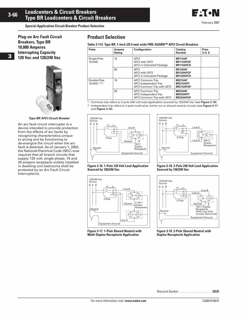
February 2007
3-66
For more information visit: www.eaton.com CA08101001E
Loadcenters & Circuit Breakers
3
Type BR Loadcenters & Circuit BreakersSpecial Application Circuit Breaker Product Selection
Plug-on Arc Fault Circuit Breakers, Type BR10,000 Amperes Interrupting Capacity120 Vac and 120/240 Vac
Type BR AFCI Circuit Breaker
An arc fault circuit interrupter is a device intended to provide protection from the effects of arc faults by recognizing characteristics unique to arcing and by functioning to de-energize the circuit when the arc fault is detected. As of January 1, 2002, the National Electrical Code (NEC) now requires that all branch circuits that supply 125 volt, single-phase, 15 and 20 ampere receptacle outlets installed in dwelling unit bedrooms shall be protected by an Arc Fault Circuit Interrupter(s).
Product SelectionTable 3-113. Type BR, 1-Inch (25.4 mm) wide FIRE-GUARD™ AFCI Circuit Breakers
� Common trip refers to 2-pole 240 volt load application sourced by 120/240 Vac (see Figure 3-18).� Independent trip refers to 2-pole multi-wire, home run or shared neutral circuits (see Figure 3-17
and Figure 3-19).
Figure 3-16. 1-Pole 120 Volt Load Application Sourced by 120/240 Vac
Figure 3-17. 1-Pole Shared Neutral with Multi-Duplex Receptacle Application
Figure 3-18. 2-Pole 240 Volt Load Application Sourced by 120/240 Vac
Figure 3-19. 2-Pole Shared Neutral with Duplex Receptacle Application
Poles Ampere
Rating
Configuration Catalog
Number
Price
U.S. $
Single-Pole10 kAIC
15 AFCI AFCI with GFCIAFCI in Clamshell Package
BR115AF
BR115AFGF
BR115AFCS
20 AFCI AFCI with GFCIAFCI in Clamshell Package
BR120AF
BR120AFGF
BR120AFCS
Double-Pole10 kAIC ��
15 AFCI Common TripAFCI Independent TripAFCI Common Trip with GFCI
BR215AF
BR215AFIT
BR215AFGF
20 AFCI Common TripAFCI Independent TripAFCI Common Trip with GFCI
BR220AF
BR220AFIT
BR220AFGF
N A B
120/240 VacSource
120 VDuplexReceptacle
1 Pole
Line B
Neutral
Neutral
Equipment Ground
N A B
120/240 VacSource
2-120 VDuplexReceptacles
2 Pole
Line B
Line A
Neutral
Neutral
Equipment Ground
Discount Symbol . . . . . . . . . . . . . . . . . . . . . . . . 22CD
Line B
N A B
120/240 VacSource
Line A 240 VDuplexReceptacle
2 Pole
Neutral
Equipment Ground
N A B
120/240 VacSource
Line A
120 V DuplexReceptacle(With Line SideJumper Removed)
2 Pole
Line B
Neutral
Neutral
Equipment Ground
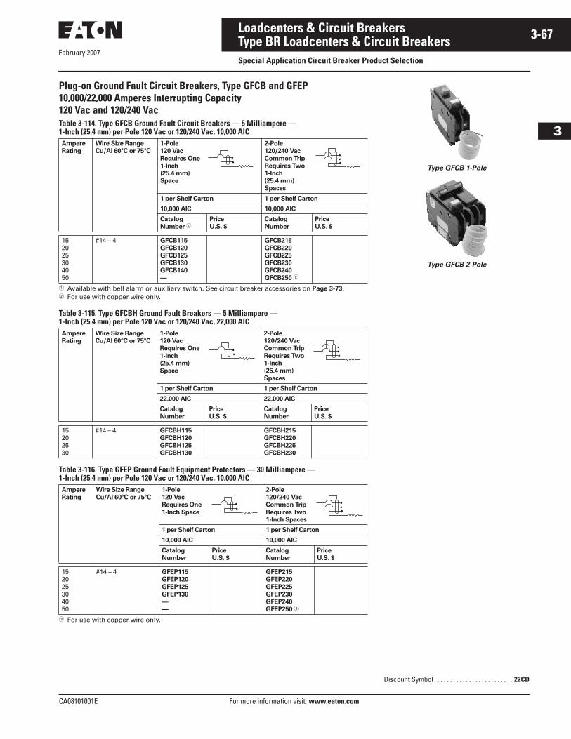
CA08101001E For more information visit: www.eaton.com
3-67Loadcenters & Circuit Breakers
February 2007
3
Type BR Loadcenters & Circuit BreakersSpecial Application Circuit Breaker Product Selection
Plug-on Ground Fault Circuit Breakers, Type GFCB and GFEP10,000/22,000 Amperes Interrupting Capacity120 Vac and 120/240 VacTable 3-114. Type GFCB Ground Fault Circuit Breakers — 5 Milliampere —1-Inch (25.4 mm) per Pole 120 Vac or 120/240 Vac, 10,000 AIC
� Available with bell alarm or auxiliary switch. See circuit breaker accessories on Page 3-73.� For use with copper wire only.
Table 3-115. Type GFCBH Ground Fault Breakers — 5 Milliampere —1-Inch (25.4 mm) per Pole 120 Vac or 120/240 Vac, 22,000 AIC
Table 3-116. Type GFEP Ground Fault Equipment Protectors — 30 Milliampere — 1-Inch (25.4 mm) per Pole 120 Vac or 120/240 Vac, 10,000 AIC
� For use with copper wire only.
Ampere
Rating
Wire Size Range
Cu/Al 60°C or 75°C
1-Pole
120 Vac
Requires One
1-Inch
(25.4 mm)
Space
2-Pole
120/240 Vac
Common Trip
Requires Two
1-Inch
(25.4 mm)
Spaces
1 per Shelf Carton 1 per Shelf Carton
10,000 AIC 10,000 AIC
Catalog
Number �Price
U.S. $
Catalog
Number
Price
U.S. $
152025304050
#14 – 4 GFCB115
GFCB120
GFCB125
GFCB130
GFCB140
—
GFCB215
GFCB220
GFCB225
GFCB230
GFCB240
GFCB250 �
Ampere
Rating
Wire Size Range
Cu/Al 60°C or 75°C
1-Pole
120 Vac
Requires One
1-Inch
(25.4 mm)
Space
2-Pole
120/240 Vac
Common Trip
Requires Two
1-Inch
(25.4 mm)
Spaces
1 per Shelf Carton 1 per Shelf Carton
22,000 AIC 22,000 AIC
Catalog
Number
Price
U.S. $
Catalog
Number
Price
U.S. $
15202530
#14 – 4 GFCBH115
GFCBH120
GFCBH125
GFCBH130
GFCBH215
GFCBH220
GFCBH225
GFCBH230
Ampere
Rating
Wire Size Range
Cu/Al 60°C or 75°C
1-Pole
120 Vac
Requires One
1-Inch Space
2-Pole
120/240 Vac
Common Trip
Requires Two
1-Inch Spaces
1 per Shelf Carton 1 per Shelf Carton
10,000 AIC 10,000 AIC
Catalog
Number
Price
U.S. $
Catalog
Number
Price
U.S. $
152025304050
#14 – 4 GFEP115
GFEP120
GFEP125
GFEP130
—
—
GFEP215
GFEP220
GFEP225
GFEP230
GFEP240
GFEP250 �
Type GFCB 1-Pole
Type GFCB 2-Pole
Discount Symbol . . . . . . . . . . . . . . . . . . . . . . . . . 22CD
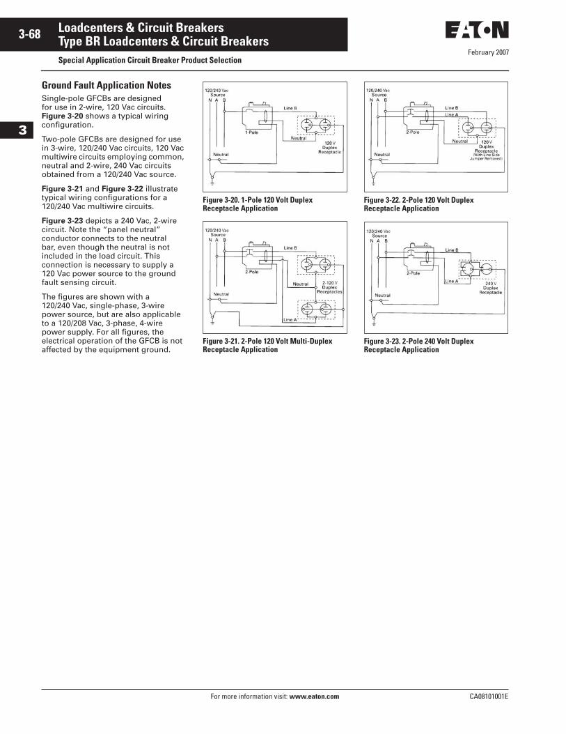
February 2007
3-68
For more information visit: www.eaton.com CA08101001E
Loadcenters & Circuit Breakers
3
Type BR Loadcenters & Circuit BreakersSpecial Application Circuit Breaker Product Selection
Ground Fault Application NotesSingle-pole GFCBs are designed for use in 2-wire, 120 Vac circuits. Figure 3-20 shows a typical wiring configuration.
Two-pole GFCBs are designed for use in 3-wire, 120/240 Vac circuits, 120 Vac multiwire circuits employing common, neutral and 2-wire, 240 Vac circuits obtained from a 120/240 Vac source.
Figure 3-21 and Figure 3-22 illustrate typical wiring configurations for a 120/240 Vac multiwire circuits.
Figure 3-23 depicts a 240 Vac, 2-wire circuit. Note the “panel neutral” conductor connects to the neutral bar, even though the neutral is not included in the load circuit. This connection is necessary to supply a 120 Vac power source to the ground fault sensing circuit.
The figures are shown with a 120/240 Vac, single-phase, 3-wire power source, but are also applicable to a 120/208 Vac, 3-phase, 4-wire power supply. For all figures, the electrical operation of the GFCB is not affected by the equipment ground.
Figure 3-20. 1-Pole 120 Volt Duplex Receptacle Application
Figure 3-21. 2-Pole 120 Volt Multi-Duplex Receptacle Application
Figure 3-22. 2-Pole 120 Volt Duplex Receptacle Application
Figure 3-23. 2-Pole 240 Volt Duplex Receptacle Application
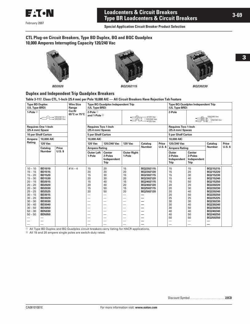
February 2007
CA08101001E For more information visit: www.eaton.com
3-69Loadcenters & Circuit Breakers
3
Type BR Loadcenters & Circuit BreakersSpecial Application Circuit Breaker Product Selection
CTL Plug-on Circuit Breakers, Type BD Duplex, BQ and BQC Quadplex10,000 Amperes Interrupting Capacity 120/240 Vac
BD2020 BQ2302115 BQ230230
Duplex and Independent Trip Quadplex BreakersTable 3-117. Class CTL, 1-Inch (25.4 mm) per Pole 10,000 AIC — All Circuit Breakers Have Rejection Tab Feature
� All Type BD Duplex and BQ Quadplex circuit breakers carry listing for HACR applications.� All 15 and 20 ampere single poles are switch-duty rated.
Type BD Duplex
(UL Type BRD)
Wire Size
Range
Cu/Al
65°C or 75°C
Type BQ Quadplex Independent Trip
(UL Type BRD)
Type BQ Quadplex Independent Trip
(UL Type BRD)
1-Pole � 2-Pole �
and 1-Pole �2-Pole
Requires One 1-Inch
(25.4 mm) Space
Requires Two 1-Inch
(25.4 mm) Spaces
Requires Two 1-Inch
(25.4 mm) Spaces
10 per Shelf Carton 5 per Shelf Carton 5 per Shelf Carton
Ampere
Rating
10,000 AIC 10,000 AIC 10,000 AIC
120 Vac 120 Vac 120/240 Vac 120 Vac Catalog
Number
Price
U.S. $
120/240 Vac Catalog
Number
Price
U.S. $Catalog
Number
Price
U.S. $
Ampere Rating Ampere Rating
Outer Left
1-Pole
Center
2-Poles
Independent
Trip
Outer Right
1-Pole
Outer
2-Poles
Independent
Trip
Center
2-Poles
Independent
Trip
10 – 1015 – 1515 – 2015 – 3020 – 1520 – 2020 – 3025 – 2530 – 1530 – 2030 – 3030 – 4030 – 5050 – 3050 – 50———
BD1010
BD1515
BD1520
BD1530
BD2015
BD2020
BD2030
BD2525
BD3015
BD3020
BD3030
BD3040
BD3050
BD5030
BD5050
———
#14 – 4 1520152015201520——————————
2020303040405050——————————
1520152015201520——————————
BQ2202115
BQ2202120
BQ2302115
BQ2302120
BQ2402115
BQ2402120
BQ2502115
BQ2502120
—
—
—
—
—
—
—
—
—
—
15151515152020202025303030404050——
15203040502030405025304050405050——
BQ215215
BQ215220
BQ215230
BQ215240
BQ215250
BQ220220
BQ220230
BQ220240
BQ220250
BQ225225
BQ230230
BQ230240
BQ230250
BQ240240
BQ240250
BQ250250
—
—
120/240 Vac120/240 Vac
120/240 Vac
Vac
Discount Symbol . . . . . . . . . . . . . . . . . . . . . . . . . 22CD
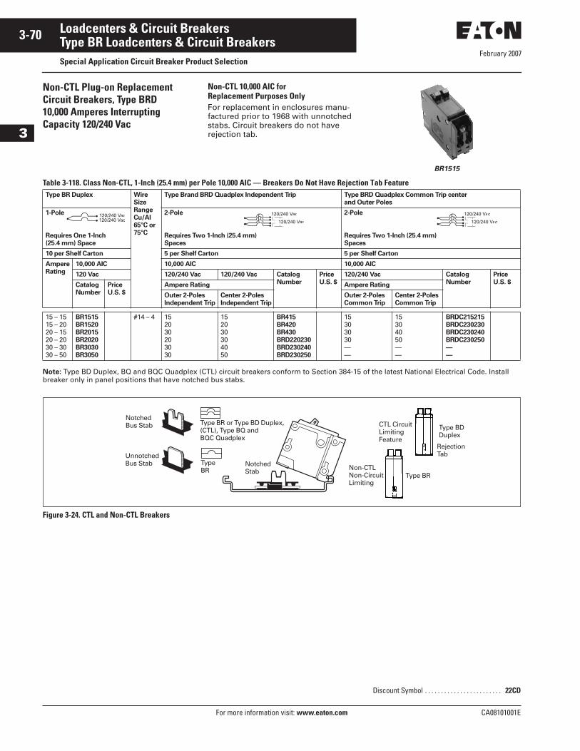
February 2007
3-70
For more information visit: www.eaton.com CA08101001E
Loadcenters & Circuit Breakers
3
Type BR Loadcenters & Circuit BreakersSpecial Application Circuit Breaker Product Selection
Non-CTL Plug-on ReplacementCircuit Breakers, Type BRD10,000 Amperes Interrupting Capacity 120/240 Vac
Non-CTL 10,000 AIC for Replacement Purposes OnlyFor replacement in enclosures manu-factured prior to 1968 with unnotched stabs. Circuit breakers do not have rejection tab.
BR1515
Table 3-118. Class Non-CTL, 1-Inch (25.4 mm) per Pole 10,000 AIC — Breakers Do Not Have Rejection Tab Feature
Note: Type BD Duplex, BQ and BQC Quadplex (CTL) circuit breakers conform to Section 384-15 of the latest National Electrical Code. Install breaker only in panel positions that have notched bus stabs.
Figure 3-24. CTL and Non-CTL Breakers
Type BR Duplex Wire
Size
Range
Cu/Al
65°C or
75°C
Type Brand BRD Quadplex Independent Trip Type BRD Quadplex Common Trip center
and Outer Poles
1-Pole
Requires One 1-Inch
(25.4 mm) Space
2-Pole
Requires Two 1-Inch (25.4 mm)
Spaces
2-Pole
Requires Two 1-Inch (25.4 mm)
Spaces
10 per Shelf Carton 5 per Shelf Carton 5 per Shelf Carton
Ampere
Rating
10,000 AIC 10,000 AIC 10,000 AIC
120 Vac 120/240 Vac 120/240 Vac Catalog
Number
Price
U.S. $
120/240 Vac Catalog
Number
Price
U.S. $Catalog
Number
Price
U.S. $
Ampere Rating Ampere Rating
Outer 2-Poles
Independent Trip
Center 2-Poles
Independent Trip
Outer 2-Poles
Common Trip
Center 2-Poles
Common Trip
15 – 1515 – 2020 – 1520 – 2030 – 3030 – 50
BR1515
BR1520
BR2015
BR2020
BR3030
BR3050
#14 – 4 152030203030
152030304050
BR415
BR420
BR430
BRD220230
BRD230240
BRD230250
15303030——
15304050——
BRDC215215
BRDC230230
BRDC230240
BRDC230250
—
—
120/240 Vac120/240 Vac
120/240 Vac
Vac
120/240 Vac
Vac
NotchedBus Stab
UnnotchedBus Stab
Type BR or Type BD Duplex, (CTL), Type BQ and BQC Quadplex
Type BR
Notched Stab Non-CTL
Non-CircuitLimiting
Type BR
Type BDDuplex
RejectionTab
CTL CircuitLimitingFeature
Discount Symbol . . . . . . . . . . . . . . . . . . . . . . . . 22CD
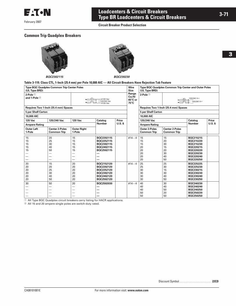
February 2007
CA08101001E For more information visit: www.eaton.com
3-71Loadcenters & Circuit Breakers
3
Type BR Loadcenters & Circuit BreakersCircuit Breaker Product Selection
Common Trip Quadplex Breakers
BQC2302115 BQC230230
Table 3-119. Class CTL, 1-Inch (25.4 mm) per Pole 10,000 AIC — All Circuit Breakers Have Rejection Tab Feature
� All Type BQC Quadplex circuit breakers carry listing for HACR applications.� All 15 and 20 ampere single poles are switch-duty rated.
Type BQC Quadplex Common Trip Center Poles
(UL Type BRD)
Wire
Size
Range
Cu/Al
65°C or
75°C
Type BQC Quadplex Common Trip Center and Outer Poles
(UL Type BRD)
2-Pole �
and 1-Pole �2-Pole �
Requires Two 1-Inch (25.4 mm) Spaces Requires Two 1-Inch (25.4 mm) Spaces
5 per Shelf Carton 5 per Shelf Carton
10,000 AIC 10,000 AIC
120 Vac 120/240 Vac 120 Vac Catalog
Number
Price
U.S. $
120/240 Vac Catalog
Number
Price
U.S. $Ampere Rating Ampere Rating
Outer Left
1-Pole
Center 2-Poles
Common Trip
Outer Right
1-Pole
Outer 2-Poles
Common Trip
Center 2-Poles
Common Trip
1515151515———
2025304050———
1515151515———
BQC2202115
BQC2252115
BQC2302115
BQC2402115
BQC2502115
—
—
—
#14 – 4 1515152020202020
1520301520304050
BQC215215
BQC215220
BQC215230
BQC220215
BQC220220
BQC220230
BQC220240
BQC220250
202020202020
152025304050
202020202020
BQC2152120
BQC2202120
BQC2252120
BQC2302120
BQC2402120
BQC2502120
#14 – 4 252530303030
253015304050
BQC225225
BQC225230
BQC230215
BQC230230
BQC230240
BQC230250
30————
50————
20————
BQC2502030
—
—
—
—
#14 – 4 4040405050
3040502050
BQC240230
BQC240240
BQC240250
BQC250220
BQC250250
120/240 Vac
Vac
Discount Symbol . . . . . . . . . . . . . . . . . . . . . . . . 22CD
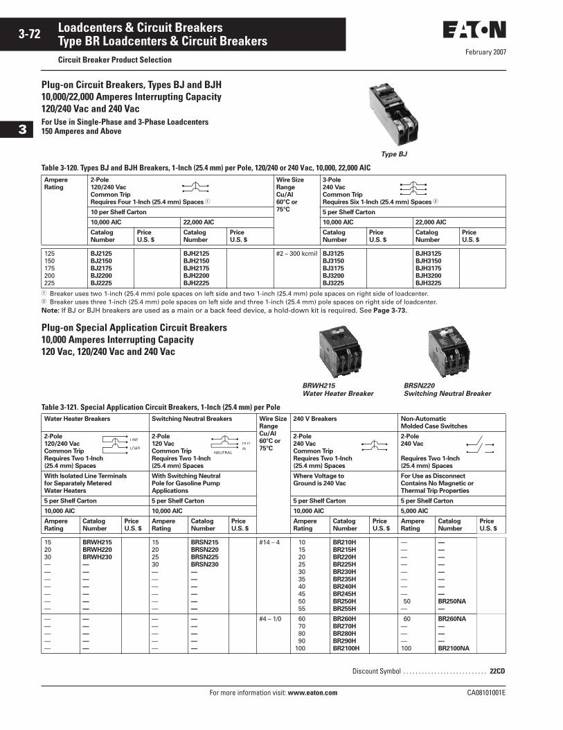
February 2007
3-72
For more information visit: www.eaton.com CA08101001E
Loadcenters & Circuit Breakers
3
Type BR Loadcenters & Circuit BreakersCircuit Breaker Product Selection
Plug-on Circuit Breakers, Types BJ and BJH10,000/22,000 Amperes Interrupting Capacity120/240 Vac and 240 VacFor Use in Single-Phase and 3-Phase Loadcenters150 Amperes and Above
Type BJ
Table 3-120. Types BJ and BJH Breakers, 1-Inch (25.4 mm) per Pole, 120/240 or 240 Vac, 10,000, 22,000 AIC
� Breaker uses two 1-inch (25.4 mm) pole spaces on left side and two 1-inch (25.4 mm) pole spaces on right side of loadcenter.� Breaker uses three 1-inch (25.4 mm) pole spaces on left side and three 1-inch (25.4 mm) pole spaces on right side of loadcenter.Note: If BJ or BJH breakers are used as a main or a back feed device, a hold-down kit is required. See Page 3-73.
Plug-on Special Application Circuit Breakers10,000 Amperes Interrupting Capacity120 Vac, 120/240 Vac and 240 Vac
BRWH215 BRSN220
Water Heater Breaker Switching Neutral Breaker
Table 3-121. Special Application Circuit Breakers, 1-Inch (25.4 mm) per Pole
Ampere
Rating
2-Pole
120/240 Vac
Common Trip
Requires Four 1-Inch (25.4 mm) Spaces �
Wire Size
Range
Cu/Al
60°C or
75°C
3-Pole
240 Vac
Common Trip
Requires Six 1-Inch (25.4 mm) Spaces �
10 per Shelf Carton 5 per Shelf Carton
10,000 AIC 22,000 AIC 10,000 AIC 22,000 AIC
Catalog
Number
Price
U.S. $
Catalog
Number
Price
U.S. $
Catalog
Number
Price
U.S. $
Catalog
Number
Price
U.S. $
125150175200225
BJ2125
BJ2150
BJ2175
BJ2200
BJ2225
BJH2125
BJH2150
BJH2175
BJH2200
BJH2225
#2 – 300 kcmil BJ3125
BJ3150
BJ3175
BJ3200
BJ3225
BJH3125
BJH3150
BJH3175
BJH3200
BJH3225
Water Heater Breakers Switching Neutral Breakers Wire Size
Range
Cu/Al
60°C or
75°C
240 V Breakers Non-Automatic
Molded Case Switches
2-Pole
120/240 Vac
Common Trip
Requires Two 1-Inch
(25.4 mm) Spaces
2-Pole
120 Vac
Common Trip
Requires Two 1-Inch
(25.4 mm) Spaces
2-Pole
240 Vac
Common Trip
Requires Two 1-Inch
(25.4 mm) Spaces
2-Pole
240 Vac
Requires Two 1-Inch
(25.4 mm) Spaces
With Isolated Line Terminals
for Separately Metered
Water Heaters
With Switching Neutral
Pole for Gasoline Pump
Applications
Where Voltage to
Ground is 240 Vac
For Use as Disconnect
Contains No Magnetic or
Thermal Trip Properties
5 per Shelf Carton 5 per Shelf Carton 5 per Shelf Carton 5 per Shelf Carton
10,000 AIC 10,000 AIC 10,000 AIC 5,000 AIC
Ampere
Rating
Catalog
Number
Price
U.S. $
Ampere
Rating
Catalog
Number
Price
U.S. $
Ampere
Rating
Catalog
Number
Price
U.S. $
Ampere
Rating
Catalog
Number
Price
U.S. $
152030———————
BRWH215
BRWH220
BRWH230
—
—
—
—
—
—
—
15202530——————
BRSN215
BRSN220
BRSN225
BRSN230
—
—
—
—
—
—
#14 – 4 10152025303540455055
BR210H
BR215H
BR220H
BR225H
BR230H
BR235H
BR240H
BR245H
BR250H
BR255H
————————50
—
—
—
—
—
—
—
—
—
BR250NA
—
—————
—
—
—
—
—
—————
—
—
—
—
—
#4 – 1/0 60708090
100
BR260H
BR270H
BR280H
BR290H
BR2100H
60———100
BR260NA
—
—
—
BR2100NA
Discount Symbol . . . . . . . . . . . . . . . . . . . . . . . . . . . 22CD
LINE
LOADOUTIN
NEUTRAL
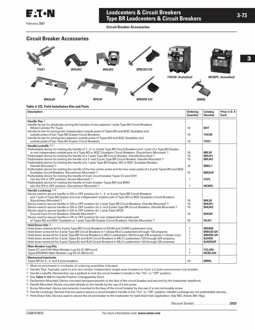
February 2007
CA08101001E For more information visit: www.eaton.com
3-73Loadcenters & Circuit Breakers
3
Type BR Loadcenters & Circuit BreakersCircuit Breaker Accessories
Circuit Breaker Accessories
Table 3-122. Field Installation Kits and Parts
� Must be purchased in multiples of ordering quantities indicated.� Handle Ties: Typically used to join two similar independent single-pole breakers to form a 2-pole noncommon trip breaker.� Handle Lockoffs: Devices that use a padlock to lock the circuit breaker’s handle in the “On” or “Off” position.� See Table 3-124 for Handle Position Changeability Chart.� Escutcheon Mounted: Device mounted semipermanently to the face of the circuit breaker and secured by the loadcenter deadfront.� Handle Mounted: Device mounted directly to the handle by the use of a set screw.� Screw Mounted: Device permanently mounted to the face of the circuit breaker by the use of a non-removable screw. Handle Lockdogs: Devices that are used to secure a circuit breaker’s handle in the “On” or “Off” position. Handle Lockdogs are not padlockable devices. Hold-Down Kits: Devices used to secure the circuit breaker to the loadcenter for back-feed main application. See NEC Article 384-16(g).
Description Ordering
Quantity �Catalog
Number
Price U.S. $
Each
Handle Ties �
Handle tie bar for physically joining the handles of two adjacent 1-pole Type BR Circuit Breakers. (Metal Cylinder Pin Type)
Handle tie bar for joining two independent outside poles of Types BQ and BQC Quadplex and outside poles of two Type BD Duplex Circuit Breakers.
Handle tie bar for joining two adjacent outside poles of Types BQ and BQC Quadplex and outside poles of two Type BD Duplex Circuit Breakers.
10
10
10
BHT
THOW
THS1
Handle Lockoffs ��
Padlockable device for locking the handle of 1-, 2- or 3-pole Type BR Circuit Breakers and 1-pole of a Type BD Duplex or one independent outside pole of a Type BQ or BQC Quadplex Circuit Breakers. (Escutcheon Mounted) �
Padlockable device for locking the handle of a 1-pole Type BR Circuit Breaker. (Handle Mounted) �Padlockable device for locking the handle of a 2- and 3-pole Type BR Circuit Breaker. (Handle Mounted) �Padlockable device for locking the handle of a 1-pole Type BD Duplex, BQ or BQC Quadplex Breaker.
(Handle Mounted) �Padlockable device for locking the handle of the two center poles and the two outer poles of a 2-pole Types BQ and BQC
Quadplex Circuit Breakers. (Escutcheon Mounted) �Padlockable device for locking the handle of main circuit breaker Types CC and CHH
into the ON or OFF position. (Screw Mounted) � Padlockable device for locking the handle of main breaker Types BW and BWH
into the ON or OFF position. (Escutcheon Mounted) �
101010
10
10
1
1
BRLW
BRLW1
BRLW2
BRDL1
BRQLW
CCPL
MCBPL
Handle Lockdogs �
Device used to secure handle in ON or OFF position for 1-, 2- or 3-pole Type BR Circuit Breakers and 1-pole of Type BD Duplex and one independent outside pole of Type BQ or BQC Quadplex Circuit Breakers. (Escutcheon Mounted) �
Device used to secure handle in ON or OFF position for 1-pole Type BR Circuit Breakers. (Handle Mounted) �Device used to secure handle in ON or OFF position for 2- and 3-pole Type BR Circuit Breakers. (Handle Mounted) �Device used to secure handle in ON or OFF position for 1-pole Type GFCB
Ground Fault Circuit Breakers. (Handle Mounted) �Device used to secure handle in ON or OFF position for one independent outside pole
of Types BQ and BQC Quadplex or 1-pole Type BD Duplex Circuit Breakers. (Handle Mounted) �
101010
10
10
BHLW
BHLW1
BHLW2
BHGW
HLW1
Hold-Down Kits
Hold-down retainer kit for 3-pole Type BR Circuit Breakers in S3100 and 3100R Loadcenters only.Hold-down screw kit for 2-pole Type BR Circuit Breakers in 1-phase MLO Loadcenters through 125 amperes.Hold-down screw kit for 2-pole Type BR Circuit Breakers in MLO Loadcenters 150 through 225 amperes (1-phase only).Hold-down screw kit for 2-pole Types BJ and BJH Circuit Breakers in MLO Loadcenters 125 through 225 amperes.Hold-down screw kit for 3-pole Types BJ and BJH Circuit Breakers in MLO Loadcenters 125 through 225 amperes.
11111
BRHDB
BREQS125
BRHDK125
BJHDS
BJHDS3P
Main Breaker Lug Kits
Types CC and CHH Main Breaker Lug Kit (2) 300 kcmil.Types BW/BWH Main Breaker Lug Kit (2) 300 kcmil.
11
CCL300
MCBL300
Mechanical Interlocks
Types BR for 2-, 3- and 4-pole breakers. 10 BRML
BREQS125BHLW2THS1 BRLW2
BHLWBRQLW BRHDK125
THOW (Installed) MCBPL (Installed)
BRML
Discount Symbol . . . . . . . . . . . . . . . . . . . . . . . . . 22CD
February 2007
3-74
For more information visit: www.eaton.com CA08101001E
Loadcenters & Circuit Breakers
3
Type BR Loadcenters & Circuit BreakersCircuit Breaker Accessories
Table 3-123. Shunt Trips, Auxiliary and Alarm Contacts
� Add suffix indicated to end of breaker catalog number.� Add amount shown to circuit breaker list price.
Table 3-124. Handle Position Changeability ChartDescription Catalog
Number �
Suffix Adder
Price U.S. $ �
Adder Each
Shunt Trip for Types BW/BWH12 Volts24 Volts
120 Volts
SR12
SR24
SR01
Shunt Trip for Types BR120 Volts ST
Auxiliary Contact for Types BW/BWH
(1) NO and (1) NC(2) NO and (2) NC
AL1
AL2
Alarm Contacts for Types BW/BWHTypes BW/BWH CR1
Alarm Contacts for Type GFCB (1-Pole)Alarm Contact for GFCB (1-Pole)(1) NO and (1) NC
W1
W2
Handle Lockoff and
Lockdog Types
To Change Handle Position from
“On to “Off,” or “Off” to “On”
You Must...
Remove
Padlock
Remove
Device
Remove
Loadcenter
Deadfront
Lockoff Escutcheon MountedLockoff Handle MountedLockoff Screw Mounted
RemoveRemoveRemove
—Remove—
———
Lockdog Escutcheon MountedLockdog Handle Mounted
N/AN/A
RemoveRemove
Remove—
Discount Symbol . . . . . . . . . . . . . . . . . . . . . . . . . 22CD
February 2007
CA08101001E For more information visit: www.eaton.com
3-75Loadcenters & Circuit Breakers
3
Type BR Loadcenters & Circuit BreakersTechnical Data and Specifications
Technical Data and Specifications
Residential/Commercial/New York City Loadcenters,Unit Enclosures — Box SizesNote: Box sizes do not include covers/fronts.
Table 3-125. Residential Loadcenters — NEMA Type 1 Indoor
Table 3-126. Residential Loadcenters — NEMA Type 3R Outdoor
Table 3-127. Commercial Loadcenters — NEMA Type 1 Indoor
Table 3-128. Commercial Loadcenters — NEMA Type 3R Outdoor
Table 3-129. New York City Loadcenters — NEMA Type 1 Indoor
Table 3-130. Types ECB and ECC Unit Enclosures — NEMA Type 1 Indoor
Table 3-131. Types ECB and ECC Unit Enclosures — NEMA Type 3R Outdoor
Box
Size
Dimensions in Inches Dimensions in mm
Height Width Depth Height Width Depth
A1B1B2C1C2C4D1G1L1L22345679
15.0016.7518.7521.0023.0027.0029.1334.1339.0045.00 8.63 9.4413.00 9.4412.0013.0014.50
11.2514.3114.3114.3114.3114.3114.3114.3114.3114.31 5.00 4.5011.00 4.50 6.8811.00 6.50
3.753.883.883.883.883.883.883.883.883.883.503.003.563.004.503.563.50
381.0425.5476.3533.4584.2685.8739.8866.8990.6
1143.0219.1239.7330.2239.7304.8330.2368.3
285.8363.5363.5363.5363.5363.5363.5363.5363.5363.5127.0114.3279.4114.3174.6279.4165.1
95.398.498.498.498.498.498.498.498.498.488.976.290.576.2
114.390.588.9
Box
Size
Dimensions in Inches Dimensions in mm
Height Width Depth Height Width Depth
B1RB2RC3RD1RG1RL1RL2R2R3R4R5R6R7R8R9RC1R
16.7518.7525.0029.1334.1339.0045.00 8.63 9.4413.00 9.4411.7513.0027.0014.2521.00
14.3114.3114.3114.3114.3114.3114.31 5.00 4.5011.00 4.50 6.5011.0010.50 6.5014.31
5.195.195.195.195.195.195.193.503.003.563.004.503.564.754.005.19
425.5476.3635.0739.8866.8990.6
1143.0219.1239.7330.2239.7298.5330.2685.8362.0533.4
363.5363.5363.5363.5363.5363.5363.5127.0114.3279.4114.3165.1279.4266.7165.1363.5
131.8131.8131.8131.8131.8131.8131.888.976.290.576.2
114.390.5
120.7101.6131.8
Box Size Dimensions in Inches Dimensions in mm
Height Width Depth Height Width Depth
19202224
44.0044.0054.0066.50
16.1616.1616.2216.22
6.256.256.316.31
1117.61117.61371.61689.1
410.4410.4412.0412.0
158.8158.8160.3160.3
Box Size Dimensions in Inches Dimensions in mm
Height Width Depth Height Width Depth
42434647
38.0044.0054.0066.56
16.3116.3116.3116.31
6.386.386.386.38
965.21117.61371.61690.7
414.3414.3414.3414.3
161.9161.9161.9161.9
Box
Size
Dimensions in Inches Dimensions in mm
Height Width Depth Height Width Depth
ABC
38.0044.0066.50
18.1318.1318.13
5.005.006.25
965.21117.61689.1
460.4460.4460.4
127.0127.0158.8
Dimensions in Inches Dimensions in mm
Height Width Depth Height Width Depth
23.25 8.88 4.50 590.6 225.4 114.3
Dimensions in Inches Dimensions in mm
Height Width Depth Height Width Depth
23.68 9.31 5.44 601.7 236.5 138.1
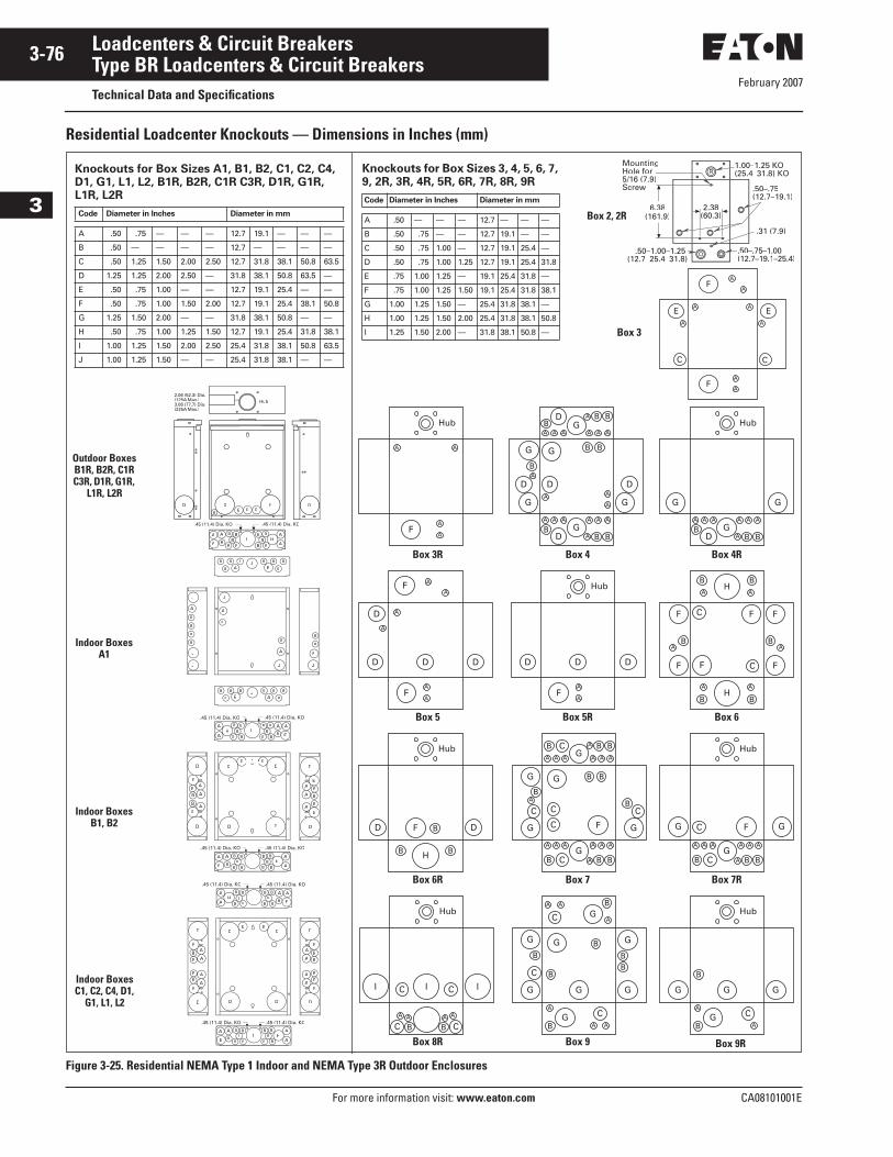
February 2007
3-76
For more information visit: www.eaton.com CA08101001E
Loadcenters & Circuit Breakers
3
Type BR Loadcenters & Circuit BreakersTechnical Data and Specifications
Residential Loadcenter Knockouts — Dimensions in Inches (mm)
Figure 3-25. Residential NEMA Type 1 Indoor and NEMA Type 3R Outdoor Enclosures
A
A
A
A
C
EA
A
C
E
F
A
AF
A
A
A A
F
Hub
A A A A
A
A A
BBBD
G
G G
Hub
J
E
B B B
AB
B B B
BE
JB B B
AB
B B B
BE
J
J
A
B
A
B
J
J
J
A
B
B
B
B
J
B
B
A
A
A A
A
A A A
A
A AB
BB
B
B
B
DG
A A A A
A
A A
BBBD
D D
G
G
G
D
G
G
Box 6R Box 7 Box 7R
Knockouts for Box Sizes A1, B1, B2, C1, C2, C4,
D1, G1, L1, L2, B1R, B2R, C1R C3R, D1R, G1R,
L1R, L2R
Code Diameter in Inches Diameter in mm
A .50 .75 — — — 12.7 19.1 — — —
B .50 — — — — 12.7 — — — —
C .50 1.25 1.50 2.00 2.50 12.7 31.8 38.1 50.8 63.5
D 1.25 1.25 2.00 2.50 — 31.8 38.1 50.8 63.5 —
E .50 .75 1.00 — — 12.7 19.1 25.4 — —
F .50 .75 1.00 1.50 2.00 12.7 19.1 25.4 38.1 50.8
G 1.25 1.50 2.00 — — 31.8 38.1 50.8 — —
H .50 .75 1.00 1.25 1.50 12.7 19.1 25.4 31.8 38.1
I 1.00 1.25 1.50 2.00 2.50 25.4 31.8 38.1 50.8 63.5
J 1.00 1.25 1.50 — — 25.4 31.8 38.1 — —
Box 8R Box 9 Box 9R
Outdoor BoxesB1R, B2R, C1R C3R, D1R, G1R,
L1R, L2R
Indoor BoxesB1, B2
Indoor BoxesC1, C2, C4, D1,
G1, L1, L2
.45 (11.4) Dia. KO
.45 (11.4) Dia. KO
A
D
E
A
A
BB
B
E
D
A
D
E
A
A
BB
B
E
D
D D
DD
E E
IA
AHB
B B
A
E B
IB B
BBB
A
AH
B BB
B
A
EB
.45 (11.4) Dia. KO
.45 (11.4) Dia. KO
A
D
E
A
A
BB
E
D
D D
DD
E E
A
BB
A
D
E
A
A
BB
B
E
D
A B
IB
BB B
A
AH
BB
B B
A
E B
IB
BBB
A
AH B
BB
A
EB
Box 5 Box 5R Box 6
Box 3R Box 4 Box 4R
Box 3
Knockouts for Box Sizes 3, 4, 5, 6, 7,
9, 2R, 3R, 4R, 5R, 6R, 7R, 8R, 9R
Code Diameter in Inches Diameter in mm
A .50 — — — 12.7 — — —
B .50 .75 — — 12.7 19.1 — —
C .50 .75 1.00 — 12.7 19.1 25.4 —
D .50 .75 1.00 1.25 12.7 19.1 25.4 31.8
E .75 1.00 1.25 — 19.1 25.4 31.8 —
F .75 1.00 1.25 1.50 19.1 25.4 31.8 38.1
G 1.00 1.25 1.50 — 25.4 31.8 38.1 —
H 1.00 1.25 1.50 2.00 25.4 31.8 38.1 50.8
I 1.25 1.50 2.00 — 31.8 38.1 50.8 —
Box 2, 2R
R–1.25 KO–31.8) KO
MountingHole for5/16 (7.9)Screw .50–.75
(12.7–19.1)2.38
(60.3)
.31 (7.9)
.50– –(12.7 19.1 25.4)
.50– –(12.7– –
6.3833(161.9)11
2.06 (52.3) Dia.(125A Max.)A3.06 (77.7) Dia.(225A Max.)A
Hub
IBB
BB B
A
AH
BBB
B B
A
E
A
B
D D D D
.45 (11.4) Dia. KO
E E EB
Indoor BoxesA1
A
A
A
A
A
A
D D D
D
F
F
A
A
D D D
F
Hub
A
A
BA
B
B
C
C
F F
FF
AB
F
F
H
A
B
A
BH
F
B B
B
H
Hub
D D
A
A
AA
A
AAA
AAA AAA
B B B
A B B
B
BB
B
C CC
C
C
B C
G
G
GG
G GF
AAA AAA
A B BB C
C
G
G GF
Hub
A A
BC
C
Hub
I
AA
B C
C II
A A
A
A
A A
B
B
B
B
B BB
C
C
C
G
GG
G
G
G G
G
A
A
B
B
C
GG
G
G
Hub
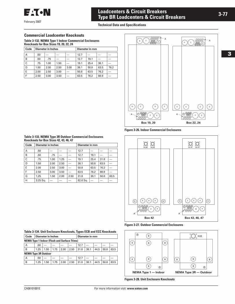
February 2007
CA08101001E For more information visit: www.eaton.com
3-77Loadcenters & Circuit Breakers
3
Type BR Loadcenters & Circuit BreakersTechnical Data and Specifications
Commercial Loadcenter KnockoutsTable 3-132. NEMA Type 1 Indoor Commercial EnclosuresKnockouts for Box Sizes 19, 20, 22, 24
Table 3-133. NEMA Type 3R Outdoor Commercial EnclosuresKnockouts for Box Sizes 42, 43, 46, 47
Table 3-134. Unit Enclosure Knockouts, Types ECB and ECC Knockouts
Figure 3-26. Indoor Commercial Enclosures
Figure 3-27. Outdoor Commercial Enclosures
Figure 3-28. Unit Enclosure Knockouts
Code Diameter in Inches Diameter in mm
A .50 — — — 12.7 — — —
B .50 .75 — — 12.7 19.1 — —
C .75 1.00 1.50 — 19.1 25.4 38.1 —
D 1.50 2.00 2.50 3.00 38.1 50.8 63.5 76.2
E 2.00 2.50 3.00 — 50.8 63.5 76.2 —
F 2.50 3.00 3.50 — 63.5 76.2 88.9 —
Code Diameter in Inches Diameter in mm
A .50 — — — 12.7 — — —
B .50 .75 — — 12.7 19.1 — —
C .75 1.00 1.25 — 19.1 25.4 31.8 —
D 1.50 2.00 2.50 — 38.1 50.8 63.5 —
E 2.00 2.50 3.00 — 50.8 63.5 76.2 —
F 2.50 3.00 3.50 — 63.5 76.2 88.9 —
G 1.25 1.50 2.00 2.50 31.8 38.1 50.8 63.5
H 3.25 Sq. — — — 82.6 Sq. — — —
Code Diameter in Inches Diameter in mm
NEMA Type 1 Indoor (Flush and Surface Trims)A .50 — — — — 12.7 — — — —
B 1.25 1.50 1.75 2.00 2.50 31.8 38.1 44.5 50.8 63.5
NEMA Type 3R OutdoorA .50 — — — — 12.7 — — — —
B 1.25 1.50 1.75 2.00 2.50 31.8 38.1 44.5 50.8 63.5
AH
EFA
C
D D D D
E
C BB
B
AH
C
E E E E
E
EFA C BB
B
Box 19, 20 Box 22, 24
G F
E E ED D
C B BB
B
A
HUB HUB
G F
F F FD D
C B BB
B
A
HUB HUB
Box 42 Box 43, 46, 47
B
B
B
B
AA
AA
B
B
B
B B
B AA
B B
HUB
NEMA Type 1 — Indoor NEMA Type 3R — Outdoor
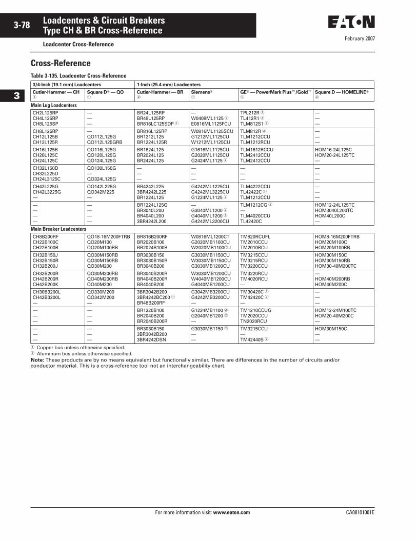
February 2007
3-78
For more information visit: www.eaton.com CA08101001E
Loadcenters & Circuit Breakers
3
Type CH & BR Cross-ReferenceLoadcenter Cross-Reference
Cross-ReferenceTable 3-135. Loadcenter Cross-Reference
� Copper bus unless otherwise specified.� Aluminum bus unless otherwise specified.Note: These products are by no means equivalent but functionally similar. There are differences in the number of circuits and/or conductor material. This is a cross-reference tool not an interchangeability chart.
3/4-Inch (19.1 mm) Loadcenters 1-Inch (25.4 mm) Loadcenters
Cutler-Hammer — CH�
Square D� — QO�
Cutler-Hammer — BR�
Siemens� �
GE� — PowerMark Plus�/Gold��
Square D — HOMELINE� �
Main Lug LoadcentersCH2L125RPCH4L125RPCH8L125SP
———
BR24L125RPBR48L125RPBR816LC125SDP �
—W0408ML1125 �E0816ML1125FCU
TPL212R �TL412R1 �TLM812S1 �
———
CH8L125RPCH12L125BCH12L125R
—QO112L125GQO112L125GRB
BR816L125RPBR1212L125BR1224L125R
W0816ML1125SCUG1212ML1125CUW1212ML1125CU
TLM812R �TLM1212CCUTLM1212RCU
———
CH16L125BCH20L125CCH24L125C
QO116L125GQO120L125GQO124L125G
BR1624L125BR2024L125BR2424L125
G1616ML1125CUG2020ML1125CUG2424ML1125 �
TLM1612RCCUTLM2412CCUTLM2412CCU
HOM16-24L125CHOM20-24L125TC—
CH32L150DCH32L225DCH24L3125C
QO130L150G—QO324L125G
———
———
———
———
CH42L225GCH42L3225G—
QO142L225GQO342M225—
BR4242L2253BR4242L225BR1224L125
G4242ML1225CUG4242ML3225CUG1224ML1125 �
TLM4222CCUTL42422C �TLM1212CCU
———
————
————
BR1224L125GBR3040L200BR4040L2003BR4242L200
—G3040ML1200 �G4040ML1200 �G4242ML3200CU
TLM1212CG �—TLM4020CCUTL42420C
HOM12-24L125TCHOM3040L200TCHOM40L200C—
Main Breaker LoadcentersCH8B200RFCH22B100CCH22B100R
QO18-16M200FTRBQO20M100QO20M100RB
BR816B200RFBR2020B100BR2024B100R
W0816ML1200CTG2020MB1100CUW2020MB1100CU
TM820RCUFLTM2010CCUTM2010RCU
HOM8-16M200FTRBHOM20M100CHOM20M100RB
CH32B150JCH32B150RCH32B200J
QO30M150RBQO30M150RBQO30M200
BR3030B150BR3030B150RBR3040B200
G3030MB1150CUW3030MB1150CUG3030MB1200CU
TM3215CCUTM3215RCUTM3220CCU
HOM30M150CHOM30M150RBHOM30-40M200TC
CH32B200RCH42B200RCH42B200K
QO30M200RBQO40M200RBQO40M200
BR3040B200RBR4040B200RBR4040B200
W3030MB1200CUW4040MB1200CUG4040MB1200CU
TM3220RCUTM4020RCU—
—HOM40M200RBHOM40M200C
CH30B3200LCH42B3200L—
QO330M200QO342M200—
3BR3042B2003BR4242BC200 �BR48B200RF
G3042MB3200CUG4242MB3200CU—
TM30420C �TM42420C �—
———
———
———
BR1220B100BR2040B200BR2040B200R
G1224MB1100 �G2040MB1200 �—
TM1210CCUGTM2020CCUTN2020RCU
HOM12-24M100TCHOM20-40M200C—
———
———
BR3030B1503BR3042B2003BR4242DSN
G3030MB1150 �——
TM3215CCU—TM42440S �
HOM30M150C——
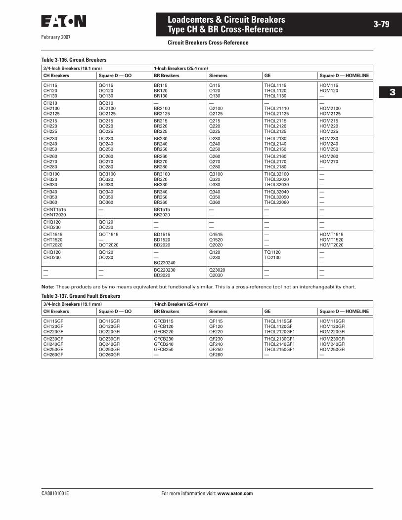
February 2007
CA08101001E For more information visit: www.eaton.com
3-79Loadcenters & Circuit Breakers
3
Type CH & BR Cross-ReferenceCircuit Breakers Cross-Reference
Table 3-136. Circuit Breakers
Note: These products are by no means equivalent but functionally similar. This is a cross-reference tool not an interchangeability chart.
Table 3-137. Ground Fault Breakers
3/4-Inch Breakers (19.1 mm) 1-Inch Breakers (25.4 mm)
CH Breakers Square D — QO BR Breakers Siemens GE Square D — HOMELINE
CH115CH120CH130
QO115QO120QO130
BR115BR120BR130
Q115Q120Q130
THQL1115THQL1120THQL1130
HOM115HOM120—
CH210CH2100CH2125
QO210QO2100QO2125
—BR2100BR2125
—Q2100Q2125
—THQL21110THQL21125
—HOM2100HOM2125
CH215CH220CH225
QO215QO220QO225
BR215BR220BR225
Q215Q220Q225
THQL2115THQL2120THQL2125
HOM215HOM220HOM225
CH230CH240CH250
QO230QO240QO250
BR230BR240BR250
Q230Q240Q250
THQL2130THQL2140THQL2150
HOM230HOM240HOM250
CH260CH270CH280
QO260QO270QO280
BR260BR270BR280
Q260Q270Q280
THQL2160THQL2170THQL2180
HOM260HOM270—
CH3100CH320CH330
QO3100QO320QO330
BR3100BR320BR330
Q3100Q320Q330
THQL32100THQL32020THQL32030
———
CH340CH350CH360
QO340QO350QO360
BR340BR350BR360
Q340Q350Q360
THQL32040THQL32050THQL32060
———
CHNT1515CHNT2020
——
BR1515BR2020
——
——
——
CHQ120CHQ230
QO120QO230
——
——
——
——
CHT1515CHT1520CHT2020
QOT1515—QOT2020
BD1515BD1520BD2020
Q1515Q1520Q2020
———
HOMT1515HOMT1520HOMT2020
CHQ120CHQ230—
QO120QO230—
——BQ230240
Q120Q230—
TQ1120TQ2130—
———
——
——
BQ220230BD3020
Q23020Q2030
——
——
3/4-Inch Breakers (19.1 mm) 1-Inch Breakers (25.4 mm)
CH Breakers Square D — QO BR Breakers Siemens GE Square D — HOMELINE
CH115GFCH120GFCH220GF
QO115GFIQO120GFIQO220GFI
GFCB115GFCB120GFCB220
QF115QF120QF220
THQL1115GFTHQL1120GFTHQL2120GF1
HOM115GFIHOM120GFIHOM220GFI
CH230GFCH240GFCH250GFCH260GF
QO230GFIQO240GFIQO250GFIQO260GFI
GFCB230GFCB240GFCB250—
QF230QF240QF250QF260
THQL2130GF1THQL2140GF1THQL2150GF1—
HOM230GFIHOM240GFIHOM250GFI—
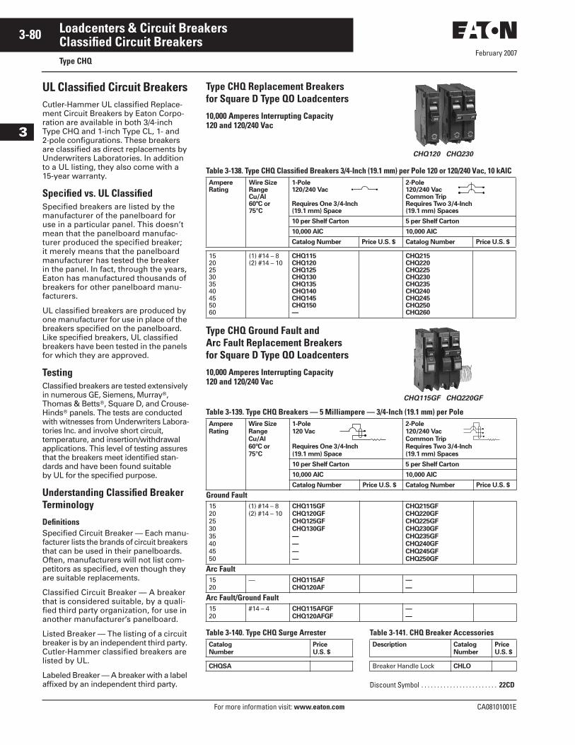
February 2007
3-80
For more information visit: www.eaton.com CA08101001E
Loadcenters & Circuit Breakers
3
Classified Circuit BreakersType CHQ
UL Classified Circuit BreakersCutler-Hammer UL classified Replace-ment Circuit Breakers by Eaton Corpo-ration are available in both 3/4-inch Type CHQ and 1-inch Type CL, 1- and 2-pole configurations. These breakers are classified as direct replacements by Underwriters Laboratories. In addition to a UL listing, they also come with a 15-year warranty.
Specified vs. UL ClassifiedSpecified breakers are listed by the manufacturer of the panelboard for use in a particular panel. This doesn’t mean that the panelboard manufac-turer produced the specified breaker; it merely means that the panelboard manufacturer has tested the breaker in the panel. In fact, through the years, Eaton has manufactured thousands of breakers for other panelboard manu-facturers.
UL classified breakers are produced by one manufacturer for use in place of the breakers specified on the panelboard. Like specified breakers, UL classified breakers have been tested in the panels for which they are approved.
TestingClassified breakers are tested extensively in numerous GE, Siemens, Murray�, Thomas & Betts�, Square D, and Crouse-Hinds� panels. The tests are conducted with witnesses from Underwriters Labora-tories Inc. and involve short circuit, temperature, and insertion/withdrawal applications. This level of testing assures that the breakers meet identified stan-dards and have been found suitable by UL for the specified purpose.
Understanding Classified Breaker Terminology
DefinitionsSpecified Circuit Breaker — Each manu-facturer lists the brands of circuit breakers that can be used in their panelboards. Often, manufacturers will not list com-petitors as specified, even though they are suitable replacements.
Classified Circuit Breaker — A breaker that is considered suitable, by a quali-fied third party organization, for use in another manufacturer’s panelboard.
Listed Breaker — The listing of a circuit breaker is by an independent third party. Cutler-Hammer classified breakers are listed by UL.
Labeled Breaker — A breaker with a label affixed by an independent third party.
Type CHQ Replacement Breakers for Square D Type QO Loadcenters
10,000 Amperes Interrupting Capacity120 and 120/240 Vac
CHQ120 CHQ230
Table 3-138. Type CHQ Classified Breakers 3/4-Inch (19.1 mm) per Pole 120 or 120/240 Vac, 10 kAIC
Type CHQ Ground Fault and Arc Fault Replacement Breakers for Square D Type QO Loadcenters
10,000 Amperes Interrupting Capacity120 and 120/240 Vac
CHQ115GF CHQ220GF
Table 3-139. Type CHQ Breakers — 5 Milliampere — 3/4-Inch (19.1 mm) per Pole
Table 3-140. Type CHQ Surge Arrester Table 3-141. CHQ Breaker Accessories
AmpereRating
Wire SizeRangeCu/Al60ºC or75°C
1-Pole120/240 Vac
Requires One 3/4-Inch (19.1 mm) Space
2-Pole120/240 VacCommon TripRequires Two 3/4-Inch (19.1 mm) Spaces
10 per Shelf Carton 5 per Shelf Carton
10,000 AIC 10,000 AIC
Catalog Number Price U.S. $ Catalog Number Price U.S. $
152025303540455060
(1) #14 – 8(2) #14 – 10
CHQ115CHQ120CHQ125CHQ130CHQ135CHQ140CHQ145CHQ150—
CHQ215CHQ220CHQ225CHQ230CHQ235CHQ240CHQ245CHQ250CHQ260
Ampere
Rating
Wire Size
Range
Cu/Al
60ºC or
75°C
1-Pole
120 Vac
Requires One 3/4-Inch
(19.1 mm) Space
2-Pole
120/240 Vac
Common Trip
Requires Two 3/4-Inch
(19.1 mm) Spaces
10 per Shelf Carton 5 per Shelf Carton
10,000 AIC 10,000 AIC
Catalog Number Price U.S. $ Catalog Number Price U.S. $
Ground Fault1520253035404550
(1) #14 – 8(2) #14 – 10
CHQ115GF
CHQ120GF
CHQ125GF
CHQ130GF
—
—
—
—
CHQ215GF
CHQ220GF
CHQ225GF
CHQ230GF
CHQ235GF
CHQ240GF
CHQ245GF
CHQ250GF
Arc Fault1520
— CHQ115AF
CHQ120AF
—
—
Arc Fault/Ground Fault1520
#14 – 4 CHQ115AFGF
CHQ120AFGF
—
—
Catalog
Number
Price
U.S. $
CHQSA
Description Catalog
Number
Price
U.S. $
Breaker Handle Lock CHLO
Discount Symbol . . . . . . . . . . . . . . . . . . . . . . . . 22CD
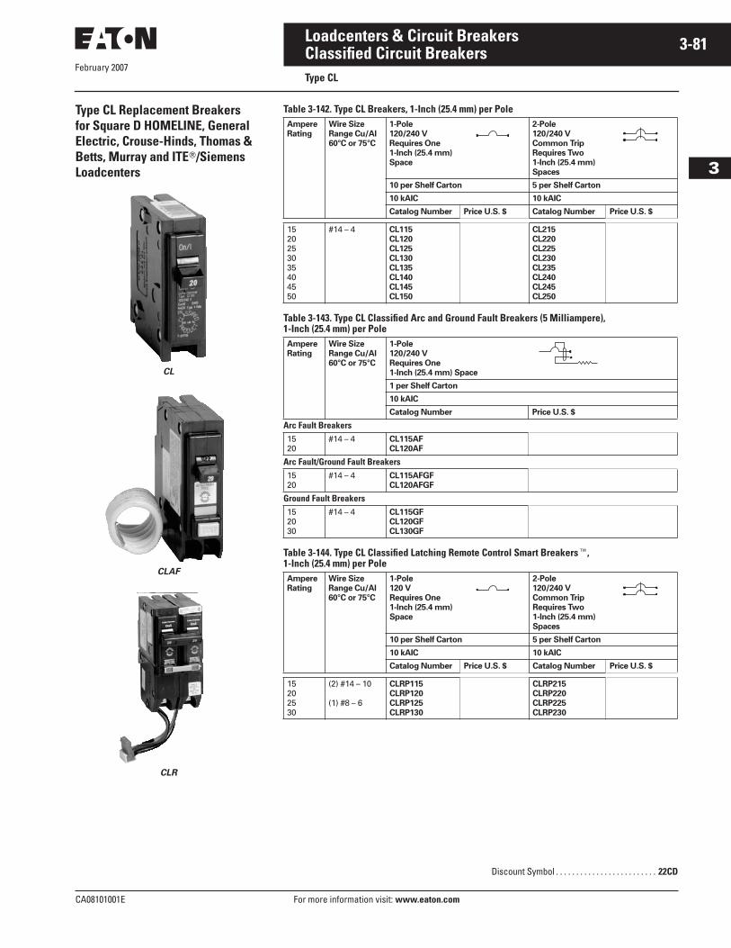
February 2007
CA08101001E For more information visit: www.eaton.com
3-81Loadcenters & Circuit Breakers
3
Classified Circuit BreakersType CL
Type CL Replacement Breakers for Square D HOMELINE, General Electric, Crouse-Hinds, Thomas & Betts, Murray and ITE�/Siemens Loadcenters
CL
CLAF
CLR
Table 3-142. Type CL Breakers, 1-Inch (25.4 mm) per Pole
Table 3-143. Type CL Classified Arc and Ground Fault Breakers (5 Milliampere), 1-Inch (25.4 mm) per Pole
Table 3-144. Type CL Classified Latching Remote Control Smart Breakers�, 1-Inch (25.4 mm) per Pole
Ampere
Rating
Wire Size
Range Cu/Al
60°C or 75°C
1-Pole
120/240 V
Requires One
1-Inch (25.4 mm)
Space
2-Pole
120/240 V
Common Trip
Requires Two
1-Inch (25.4 mm)
Spaces
10 per Shelf Carton 5 per Shelf Carton
10 kAIC 10 kAIC
Catalog Number Price U.S. $ Catalog Number Price U.S. $
1520253035404550
#14 – 4 CL115
CL120
CL125
CL130
CL135
CL140
CL145
CL150
CL215
CL220
CL225
CL230
CL235
CL240
CL245
CL250
Ampere
Rating
Wire Size
Range Cu/Al
60°C or 75°C
1-Pole
120/240 V
Requires One
1-Inch (25.4 mm) Space
1 per Shelf Carton
10 kAIC
Catalog Number Price U.S. $
Arc Fault Breakers1520
#14 – 4 CL115AF
CL120AF
Arc Fault/Ground Fault Breakers1520
#14 – 4 CL115AFGF
CL120AFGF
Ground Fault Breakers152030
#14 – 4 CL115GF
CL120GF
CL130GF
Ampere
Rating
Wire Size
Range Cu/Al
60°C or 75°C
1-Pole
120 V
Requires One
1-Inch (25.4 mm)
Space
2-Pole
120/240 V
Common Trip
Requires Two
1-Inch (25.4 mm)
Spaces
10 per Shelf Carton 5 per Shelf Carton
10 kAIC 10 kAIC
Catalog Number Price U.S. $ Catalog Number Price U.S. $
15202530
(2) #14 – 10
(1) #8 – 6
CLRP115
CLRP120
CLRP125
CLRP130
CLRP215
CLRP220
CLRP225
CLRP230
Discount Symbol . . . . . . . . . . . . . . . . . . . . . . . . . 22CD
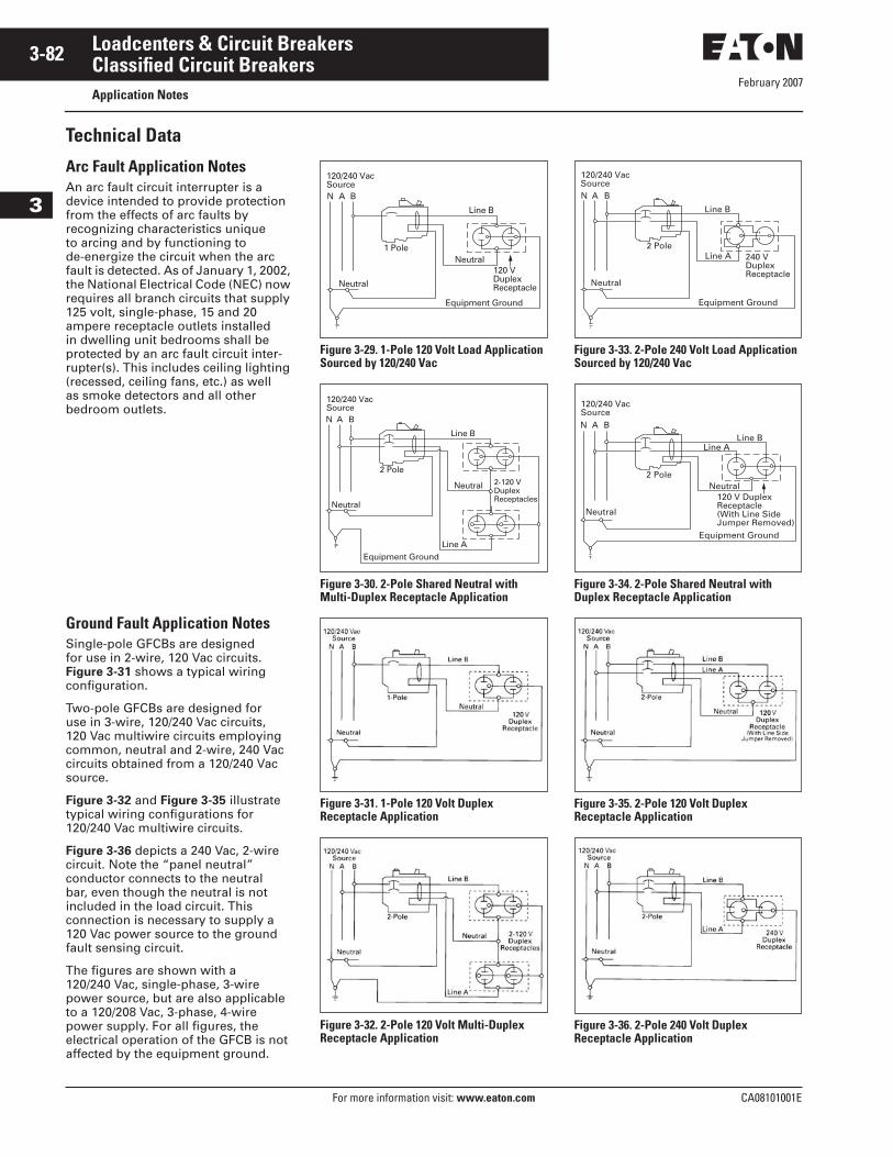
February 2007
3-82
For more information visit: www.eaton.com CA08101001E
Loadcenters & Circuit Breakers
3
Classified Circuit BreakersApplication Notes
Technical Data
Arc Fault Application NotesAn arc fault circuit interrupter is a device intended to provide protection from the effects of arc faults by recognizing characteristics unique to arcing and by functioning to de-energize the circuit when the arc fault is detected. As of January 1, 2002, the National Electrical Code (NEC) now requires all branch circuits that supply 125 volt, single-phase, 15 and 20 ampere receptacle outlets installed in dwelling unit bedrooms shall be protected by an arc fault circuit inter-rupter(s). This includes ceiling lighting (recessed, ceiling fans, etc.) as well as smoke detectors and all other bedroom outlets.
Ground Fault Application NotesSingle-pole GFCBs are designed for use in 2-wire, 120 Vac circuits. Figure 3-31 shows a typical wiring configuration.
Two-pole GFCBs are designed for use in 3-wire, 120/240 Vac circuits, 120 Vac multiwire circuits employing common, neutral and 2-wire, 240 Vac circuits obtained from a 120/240 Vac source.
Figure 3-32 and Figure 3-35 illustrate typical wiring configurations for 120/240 Vac multiwire circuits.
Figure 3-36 depicts a 240 Vac, 2-wire circuit. Note the “panel neutral” conductor connects to the neutral bar, even though the neutral is not included in the load circuit. This connection is necessary to supply a 120 Vac power source to the ground fault sensing circuit.
The figures are shown with a 120/240 Vac, single-phase, 3-wire power source, but are also applicable to a 120/208 Vac, 3-phase, 4-wire power supply. For all figures, the electrical operation of the GFCB is not affected by the equipment ground.
Figure 3-29. 1-Pole 120 Volt Load Application Sourced by 120/240 Vac
Figure 3-30. 2-Pole Shared Neutral with Multi-Duplex Receptacle Application
Figure 3-31. 1-Pole 120 Volt Duplex Receptacle Application
Figure 3-32. 2-Pole 120 Volt Multi-Duplex Receptacle Application
Figure 3-33. 2-Pole 240 Volt Load Application Sourced by 120/240 Vac
Figure 3-34. 2-Pole Shared Neutral with Duplex Receptacle Application
Figure 3-35. 2-Pole 120 Volt Duplex Receptacle Application
Figure 3-36. 2-Pole 240 Volt Duplex Receptacle Application
N A B
120/240 VacSource
120 VDuplexReceptacle
1 Pole
Line B
Neutral
Neutral
Equipment Ground
N A B
120/240 VacSource
2-120 VDuplexReceptacles
2 Pole
Line B
Line A
Neutral
Neutral
Equipment Ground
Line B
N A B
120/240 VacSource
Line A 240 VDuplexReceptacle
2 Pole
Neutral
Equipment Ground
N A B
120/240 VacSource
Line A
120 V DuplexReceptacle(With Line SideJumper Removed)
2 Pole
Line B
Neutral
Neutral
Equipment Ground
February 2007
CA08101001E For more information visit: www.eaton.com
3-83Loadcenters & Circuit Breakers
3
OEM Loadcenter InteriorsProduct Description
OEM Loadcenter Interiors
Product DescriptionAs a leader in the electrical distribution equipment business, Eaton has a unique product offering for equipment manu-facturers, panel builders and virtually any OEM that has a need for power distribution within their equipment. The OEM interior offering consists of a wide variety of power distribution options utilizing components from Cutler-Hammer CH and BR Loadcenter product lines. With high-volume, stan-dardized products, OEMs can expect to receive high-quality products covering configurations meeting virtually any power distribution need.
Coupled with Eaton’s expertise in circuit breaker design and manufacturing, our OEM interiors provide solid power distribution and circuit protection in a compact, easy-to-install package. Inte-riors are offered from 2 to 42 circuits and from 70 to 225 amperes.
QualityBuilt in our ISO 9002 certified manu-facturing facilities, customers can be assured of the process quality in place for the manufacture of these products. Utilizing the latest in com-puter-controlled plating, painting, molding, stamping and welding processes, our customers have come to expect consistent high-quality from shipment to shipment.
Two Products Offer Design FlexibilityAs a manufacturer of two lines of load-centers, we are in a unique position to offer the broadest range of interiors in the market. Each line has its own unique characteristics that appeal to various segments of the market. OEM interiors are UL recognized com-ponents and are listed in either of the following UL files: E8741 or E52977.
The CH interiors feature 100% copper bus and use the CH 3/4-inch (19.1 mm) wide circuit breaker, which minimizes panel space. Recognized by contrac-tors for its sturdy design, the CH interior will appeal to those customers seeking an industrial quality bolted bus bar and the space saving of 3/4-inch (19.1 mm) per bus stab. With a typical 12 circuit CH interior, this space savings amounts to an inch and a half savings over its 1-inch (25.4 mm) counterparts. The stab rating of the CH interiors is 140 amperes maximum meaning that the handle rating of breakers mounted across from one another may not exceed 140 amperes.
The BR interiors are manufactured of formed, plated aluminum or copper, and use the Cutler-Hammer Type BR 1-inch (25.4 mm) wide circuit breaker. This design affords customers the most circuit flexibility as many of these interi-ors allow the installation of standard 1- and 2-pole breakers as well duplex (2 poles in a 1-inch (25.4 mm) space) or quadplex (4 poles in a 2-inch (50.8 mm) space) breakers. The stab rating of the BR interiors is 200 amperes maximum, meaning that the handle rating of the breakers that are mounted across from one another may not exceed 200 amperes.
The interiors are designed for either horizontal (single-row breaker mount-ing), or vertical (double-row breaker mounting). To comply with National Electrical Code (NEC) requirements, if mounted horizontally, when the breaker is “ON,” the handle should be in the UP position. When mounted vertically, the handle toggles from left to right, so this is not a concern.
Standards and CertificationsClass CTLNational Electrical Code Paragraph 384-15 requires branch circuit panel-boards to be provided with physical means to prevent the installation of more overcurrent devices than that number of which the enclosure was designed, rated and approved. Class CTL Duplex, Quadplex and twin breakers (identified by a catalog number prefix BD, BQ, BQC and CHT) are equipped with a UL listed rejection tab over the line terminal. All OEM interiors have appropriately notched stabs to accept these rejection tab Class CTL breakers.
Duplex, Quadplex and twin breakers manufactured without the rejection tab (identified by a catalog number prefix BR, BRD and CHNT) are available for replacement purposes in older interiors.
Federal SpecificationsAll loadcenter enclosures meet Federal Specifications W-P-115b, Type 1, Class 2 requirements.
All 120/240 volt breakers, both 1-inch (25.4 mm), 1/2-inch (12.7 mm) and 3/4-inch (19.1 mm) per pole meet the requirement of Federal Specifications W-C 375B/Gen Type 1.
Canadian Standards Association ListingAll 1-pole and 2-pole, 120/240 volt breakers, both 1-inch (25.4 mm), 1/2-inch (12.7 mm) and 3/4-inch (19.1 mm) per pole, 225 ampere maximum, are listed as Certified by the Canadian Standards Association, Guide No. 69-11.19, Class 1432, File 18328.
Underwriters Laboratories ListingAll grounding bars manufactured comply with Underwriters Laboratories standards and are listed under Guide No. DHJR, File E31424, Volume W, Section 17.
All circuit breakers 10 amperes and larger comply with the Underwriters Laboratories “Standard for Branch Circuit and Service Circuit-Breakers” UL 489; Guide No. 60 10.2 File E31424, and “Requirements for Wire Connec-tors and Soldering Lugs,” UL 486B, Guide No. 461 10-C File E7830.
All Cutler-Hammer breakers where marked, are suitable for use with 60/75ºC rated wire, unless otherwise specified.
All devices comply with the 22 kAIC – 10 kAIC UL series connected compo-nents File DKSY2 of the Recognized Components Index.
Lighting and Appliance PanelboardsLighting and appliance branch circuit panelboards are defined in NEC (Article 384) as “One having more than 10 percent of its overcurrent devices rated 30 amperes or less for which neutral connections are provided.” Article 384 also limits the number of overcurrent devices (branch circuit poles) to a maximum of 42 in any one cabinet. When the 42 poles are exceeded, two or more separate panels are required.
For more details and engineering drawings, see BR.31.02.S.E.
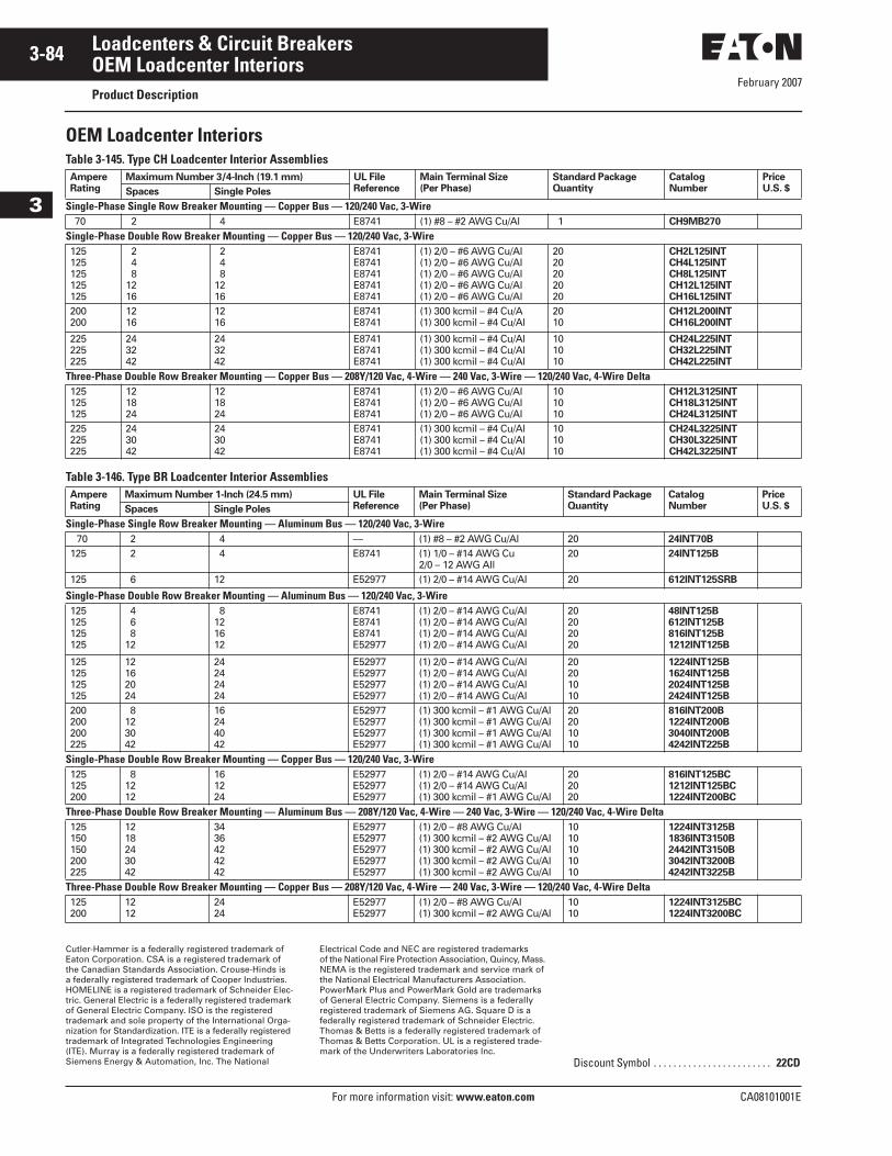
February 2007
3-84
For more information visit: www.eaton.com CA08101001E
Loadcenters & Circuit Breakers
3
OEM Loadcenter InteriorsProduct Description
OEM Loadcenter InteriorsTable 3-145. Type CH Loadcenter Interior Assemblies
Table 3-146. Type BR Loadcenter Interior Assemblies
Cutler-Hammer is a federally registered trademark of Eaton Corporation. CSA is a registered trademark of the Canadian Standards Association. Crouse-Hinds is a federally registered trademark of Cooper Industries. HOMELINE is a registered trademark of Schneider Elec-tric. General Electric is a federally registered trademark of General Electric Company. ISO is the registered trademark and sole property of the International Orga-nization for Standardization. ITE is a federally registered trademark of Integrated Technologies Engineering (ITE). Murray is a federally registered trademark of Siemens Energy & Automation, Inc. The National
Electrical Code and NEC are registered trademarks of the National Fire Protection Association, Quincy, Mass. NEMA is the registered trademark and service mark of the National Electrical Manufacturers Association. PowerMark Plus and PowerMark Gold are trademarks of General Electric Company. Siemens is a federally registered trademark of Siemens AG. Square D is a federally registered trademark of Schneider Electric. Thomas & Betts is a federally registered trademark of Thomas & Betts Corporation. UL is a registered trade-mark of the Underwriters Laboratories Inc.
AmpereRating
Maximum Number 3/4-Inch (19.1 mm) UL FileReference
Main Terminal Size(Per Phase)
Standard PackageQuantity
CatalogNumber
PriceU.S. $Spaces Single Poles
Single-Phase Single Row Breaker Mounting — Copper Bus — 120/240 Vac, 3-Wire70 2 4 E8741 (1) #8 – #2 AWG Cu/Al 1 CH9MB270
Single-Phase Double Row Breaker Mounting — Copper Bus — 120/240 Vac, 3-Wire125125125125125
248
1216
248
1216
E8741E8741E8741E8741E8741
(1) 2/0 – #6 AWG Cu/Al(1) 2/0 – #6 AWG Cu/Al(1) 2/0 – #6 AWG Cu/Al(1) 2/0 – #6 AWG Cu/Al(1) 2/0 – #6 AWG Cu/Al
2020202020
CH2L125INTCH4L125INTCH8L125INTCH12L125INTCH16L125INT
200200
1216
1216
E8741E8741
(1) 300 kcmil – #4 Cu/A(1) 300 kcmil – #4 Cu/Al
2010
CH12L200INTCH16L200INT
225225225
243242
243242
E8741E8741E8741
(1) 300 kcmil – #4 Cu/Al(1) 300 kcmil – #4 Cu/Al(1) 300 kcmil – #4 Cu/Al
101010
CH24L225INTCH32L225INTCH42L225INT
Three-Phase Double Row Breaker Mounting — Copper Bus — 208Y/120 Vac, 4-Wire — 240 Vac, 3-Wire — 120/240 Vac, 4-Wire Delta125125125
121824
121824
E8741E8741E8741
(1) 2/0 – #6 AWG Cu/Al(1) 2/0 – #6 AWG Cu/Al(1) 2/0 – #6 AWG Cu/Al
101010
CH12L3125INTCH18L3125INTCH24L3125INT
225225225
243042
243042
E8741E8741E8741
(1) 300 kcmil – #4 Cu/Al(1) 300 kcmil – #4 Cu/Al(1) 300 kcmil – #4 Cu/Al
101010
CH24L3225INTCH30L3225INTCH42L3225INT
AmpereRating
Maximum Number 1-Inch (24.5 mm) UL FileReference
Main Terminal Size(Per Phase)
Standard Package Quantity
Catalog Number
PriceU.S. $Spaces Single Poles
Single-Phase Single Row Breaker Mounting — Aluminum Bus — 120/240 Vac, 3-Wire70 2 4 — (1) #8 – #2 AWG Cu/Al 20 24INT70B
125 2 4 E8741 (1) 1/0 – #14 AWG Cu2/0 – 12 AWG All
20 24INT125B
125 6 12 E52977 (1) 2/0 – #14 AWG Cu/Al 20 612INT125SRB
Single-Phase Double Row Breaker Mounting — Aluminum Bus — 120/240 Vac, 3-Wire125125125125
468
12
8121612
E8741E8741E8741E52977
(1) 2/0 – #14 AWG Cu/Al(1) 2/0 – #14 AWG Cu/Al(1) 2/0 – #14 AWG Cu/Al(1) 2/0 – #14 AWG Cu/Al
20202020
48INT125B612INT125B816INT125B1212INT125B
125125125125
12162024
24242424
E52977E52977E52977E52977
(1) 2/0 – #14 AWG Cu/Al(1) 2/0 – #14 AWG Cu/Al(1) 2/0 – #14 AWG Cu/Al(1) 2/0 – #14 AWG Cu/Al
20201010
1224INT125B1624INT125B2024INT125B2424INT125B
200200200225
8123042
16244042
E52977E52977E52977E52977
(1) 300 kcmil – #1 AWG Cu/Al(1) 300 kcmil – #1 AWG Cu/Al(1) 300 kcmil – #1 AWG Cu/Al(1) 300 kcmil – #1 AWG Cu/Al
20201010
816INT200B1224INT200B3040INT200B4242INT225B
Single-Phase Double Row Breaker Mounting — Copper Bus — 120/240 Vac, 3-Wire125125200
81212
161224
E52977E52977E52977
(1) 2/0 – #14 AWG Cu/Al(1) 2/0 – #14 AWG Cu/Al(1) 300 kcmil – #1 AWG Cu/Al
202020
816INT125BC1212INT125BC1224INT200BC
Three-Phase Double Row Breaker Mounting — Aluminum Bus — 208Y/120 Vac, 4-Wire — 240 Vac, 3-Wire — 120/240 Vac, 4-Wire Delta125150150200225
1218243042
3436424242
E52977E52977E52977E52977E52977
(1) 2/0 – #8 AWG Cu/Al(1) 300 kcmil – #2 AWG Cu/Al(1) 300 kcmil – #2 AWG Cu/Al(1) 300 kcmil – #2 AWG Cu/Al(1) 300 kcmil – #2 AWG Cu/Al
1010101010
1224INT3125B1836INT3150B2442INT3150B3042INT3200B4242INT3225B
Three-Phase Double Row Breaker Mounting — Copper Bus — 208Y/120 Vac, 4-Wire — 240 Vac, 3-Wire — 120/240 Vac, 4-Wire Delta125200
1212
2424
E52977E52977
(1) 2/0 – #8 AWG Cu/Al(1) 300 kcmil – #2 AWG Cu/Al
1010
1224INT3125BC1224INT3200BC
Discount Symbol . . . . . . . . . . . . . . . . . . . . . . . . 22CD
Recommended