Working Group D-3, Line Protection Subcommittee
IEEE PES Power System Relaying Committee
Considerations in Choosing Directional Polarizing
Methods for Ground Overcurrent Elements in Line
Protection Applications
MAY 2014
Members, Working Group D-3 "Considerations in Choosing Directional Polarizing Methods for Ground
Overcurrent Elements in Line Protection Applications": John Appleyard, Jeffrey Barsch, Gabriel
Benmouyal, Art Buanno, Randy Crellin, Randy Cunico, Normann Fischer, Michael Fleck, Robert Frye,
Charles Henville, Meyer Kao (Chair), Shoukat Khan, Gary Kobet, Alex Lee, Don Lukach, Walter
McCannon, Joe Mooney, Jim Obrien, Cristian Paduraru, Suhag Patel, Russell Patterson, Frank Plumptre,
Elmo Price (Vice-chair), Ryland Revelle, Sinan Saygin, Mark Schroeder, Steve Turner
Table of Contents
1.0 Introduction ....................................................................................................................................... 4
2.0 Sequence Network for Ground Faults ............................................................................................. 4
3.0 Identify Different Methods of Polarizing for Ground Directional Elements ............................... 6
3.1 Zero Sequence Voltage ...............................................................................................................6
3.2 Negative Sequence Voltage .........................................................................................................8
3.3 Zero Sequence Current (Current Polarizing) ........................................................................10
3.3.1 Using the tertiary of an autotransformer for polarizing current ............................. 16
3.3.2 Specifying Polarizing CT Ratio .................................................................................... 20
3.4 Dual Polarizing, combination of zero sequence voltage and zero sequence current ..........20
3.5 Negative and Zero Sequence Impedance ................................................................................24
3.6 Virtual polarization ..................................................................................................................26
3.7 Voltage Compensation ..............................................................................................................26
4.0 Investigate Application of Different Methods ............................................................................... 29
4.1 Zero sequence mutually coupled lines.....................................................................................29
4.2 Evaluation of polarizing method considering line and source impedance, Z0 and Z2.......35
4.3 Combining multiple polarizing methods ................................................................................43
4.3.1 Dual zero-sequence polarizing ..................................................................................... 43
4.3.2 Both negative and zero-sequence polarizing (preferential based on sensitivity
thresholds) ...................................................................................................................... 43
5.0 Other Considerations ...................................................................................................................... 43
5.1 Installation and verification tests of the directional elements ..............................................43
5.2 Open pole conditions.................................................................................................................44
5.2.1 Single pole open condition affecting an adjacent line [7], [8] .................................... 44
5.3 Modeling of ground directional element in software .............................................................46
5.4 Special considerations for series compensated lines or lines near series compensated
lines and static var compensator .............................................................................................46
5.4.1 Impact of the sub-synchronous frequency component on the operation of
directional elements applied to series-compensated transmission lines ................... 47
5.5 Inherently directional; strong source impedance behind and weak forward source
impedance ..................................................................................................................................48
5.6 Mismatch of polarization methods on line terminals in communication assisted trip
scheme ........................................................................................................................................50
5.7 Current polarizing at stations with more than one transformer and split low-sides .........53
6.0 Providing Recommendation on Choosing Appropriate Method ................................................ 58
7.0 Summary .......................................................................................................................................... 59
8.0 Appendix - Examples of specific application where a particular method is inadequate .......... 59
8.1 Example 1 ..................................................................................................................................59
8.2 Example 2 ..................................................................................................................................61
8.3 Example 3 ..................................................................................................................................61
8.4 Example 4 ..................................................................................................................................64
8.5 Example 5 ..................................................................................................................................65
9.0 References and technical documents ............................................................................................. 66
4
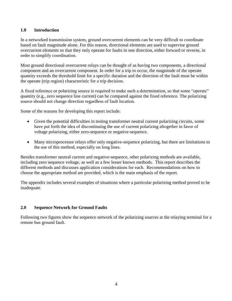
1.0 Introduction
In a networked transmission system, ground overcurrent elements can be very difficult to coordinate
based on fault magnitude alone. For this reason, directional elements are used to supervise ground
overcurrent elements so that they only operate for faults in one direction, either forward or reverse, in
order to simplify coordination.
Most ground directional overcurrent relays can be thought of as having two components, a directional
component and an overcurrent component. In order for a trip to occur, the magnitude of the operate
quantity exceeds the threshold limit for a specific duration and the direction of the fault must be within
the operate (trip region) characteristic for a trip decision.
A fixed reference or polarizing source is required to make such a determination, so that some “operate”
quantity (e.g., zero sequence line current) can be compared against the fixed reference. The polarizing
source should not change direction regardless of fault location.
Some of the reasons for developing this report include:
Given the potential difficulties in testing transformer neutral current polarizing circuits, some
have put forth the idea of discontinuing the use of current polarizing altogether in favor of
voltage polarizing, either zero-sequence or negative-sequence.
Many microprocessor relays offer only negative-sequence polarizing, but there are limitations to
the use of this method, especially on long lines.
Besides transformer neutral current and negative-sequence, other polarizing methods are available,
including zero sequence voltage, as well as a few lesser known methods. This report describes the
different methods and discusses application considerations for each. Recommendations on how to
choose the appropriate method are provided, which is the main emphasis of the report.
The appendix includes several examples of situations where a particular polarizing method proved to be
inadequate.
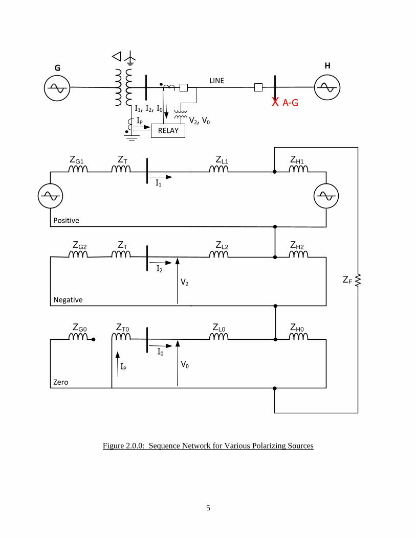
2.0 Sequence Network for Ground Faults
Following two figures show the sequence network of the polarizing sources at the relaying terminal for a
remote bus ground fault.
5
ZG1
ZG2
ZG0
ZT
ZT
ZT0
ZL1
Positive
Negative
Zero
ZH1
ZL2 ZH2
ZL0 ZH0
X A-G
G H
RELAY
I0
I1
I2
LINE
IP
V2, V0
I1, I2, I0
IP
V2
V0
ZF
Figure 2.0.0: Sequence Network for Various Polarizing Sources
6
ZG0 ZTH0
Zero
ZL0 ZH0
X A-G
G H
RELAY
I0
LINE
IP
V2, V0
I1, I2, I0
IP
V0
*
*Tertiary not loaded
ZTM0
ZTL0
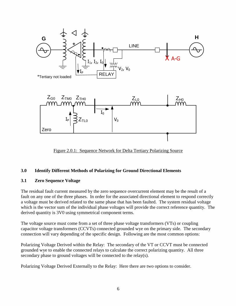
Figure 2.0.1: Sequence Network for Delta Tertiary Polarizing Source
3.0 Identify Different Methods of Polarizing for Ground Directional Elements
3.1 Zero Sequence Voltage
The residual fault current measured by the zero sequence overcurrent element may be the result of a
fault on any one of the three phases. In order for the associated directional element to respond correctly
a voltage must be derived related to the same phase that has been faulted. The system residual voltage
which is the vector sum of the individual phase voltages will provide the correct reference quantity. The
derived quantity is 3V0 using symmetrical component terms.
The voltage source must come from a set of three phase voltage transformers (VTs) or coupling
capacitor voltage transformers (CCVTs) connected grounded wye on the primary side. The secondary
connection will vary depending of the specific design. Following are the most common options:
Polarizing Voltage Derived within the Relay: The secondary of the VT or CCVT must be connected
grounded wye to enable the connected relays to calculate the correct polarizing quantity. All three
secondary phase to ground voltages will be connected to the relay(s).
Polarizing Voltage Derived Externally to the Relay: Here there are two options to consider.
7
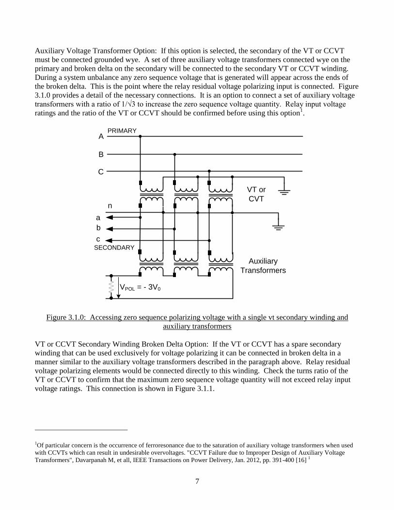
Auxiliary Voltage Transformer Option: If this option is selected, the secondary of the VT or CCVT
must be connected grounded wye. A set of three auxiliary voltage transformers connected wye on the
primary and broken delta on the secondary will be connected to the secondary VT or CCVT winding.
During a system unbalance any zero sequence voltage that is generated will appear across the ends of
the broken delta. This is the point where the relay residual voltage polarizing input is connected. Figure
3.1.0 provides a detail of the necessary connections. It is an option to connect a set of auxiliary voltage
transformers with a ratio of 1/√3 to increase the zero sequence voltage quantity. Relay input voltage
ratings and the ratio of the VT or CCVT should be confirmed before using this option1.
A
B
C
a
b
c
n
PRIMARY
SECONDARY
VPOL = - 3V0
VT or
CVT
Auxiliary
Transformers
Figure 3.1.0: Accessing zero sequence polarizing voltage with a single vt secondary winding and
auxiliary transformers
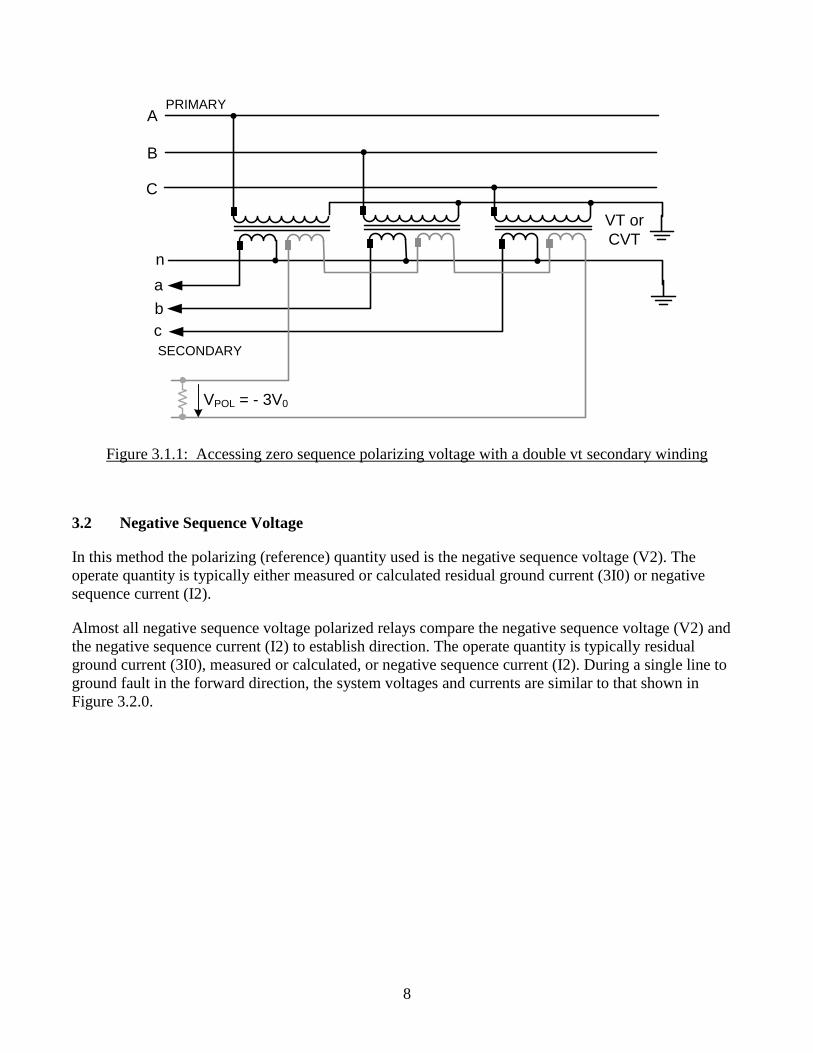
VT or CCVT Secondary Winding Broken Delta Option: If the VT or CCVT has a spare secondary
winding that can be used exclusively for voltage polarizing it can be connected in broken delta in a
manner similar to the auxiliary voltage transformers described in the paragraph above. Relay residual
voltage polarizing elements would be connected directly to this winding. Check the turns ratio of the
VT or CCVT to confirm that the maximum zero sequence voltage quantity will not exceed relay input
voltage ratings. This connection is shown in Figure 3.1.1.
1Of particular concern is the occurrence of ferroresonance due to the saturation of auxiliary voltage transformers when used
with CCVTs which can result in undesirable overvoltages. "CCVT Failure due to Improper Design of Auxiliary Voltage
Transformers", Davarpanah M, et all, IEEE Transactions on Power Delivery, Jan. 2012, pp. 391-400 [16] 1
8
A
B
C
a
b
c
n
PRIMARY
SECONDARY
VPOL = - 3V0
VT or
CVT
Figure 3.1.1: Accessing zero sequence polarizing voltage with a double vt secondary winding
3.2 Negative Sequence Voltage
In this method the polarizing (reference) quantity used is the negative sequence voltage (V2). The
operate quantity is typically either measured or calculated residual ground current (3I0) or negative
sequence current (I2).
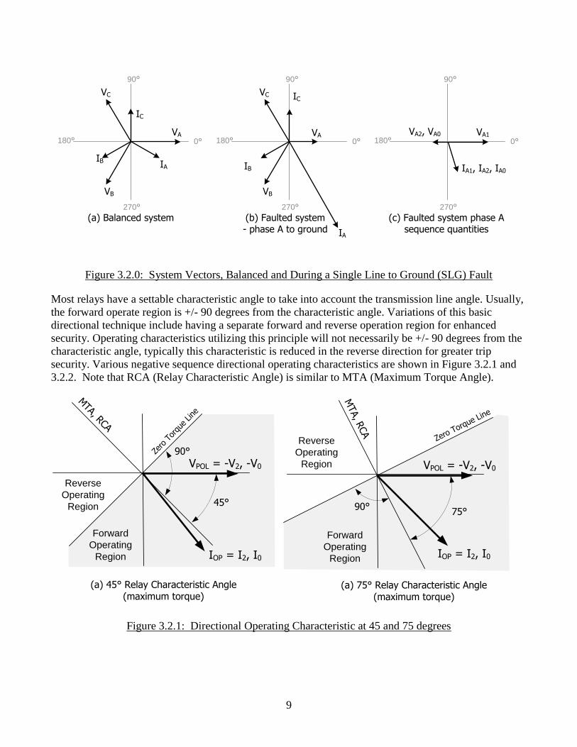
Almost all negative sequence voltage polarized relays compare the negative sequence voltage (V2) and
the negative sequence current (I2) to establish direction. The operate quantity is typically residual
ground current (3I0), measured or calculated, or negative sequence current (I2). During a single line to
ground fault in the forward direction, the system voltages and currents are similar to that shown in
Figure 3.2.0.
9
0°
90°
180°
270°
VA
VB
VC
IAIB
IC
0°
90°
180°
270°
VA
VB
VC
IA
IB
IC
0°
90°
180°
270°
VA1VA2, VA0
IA1, IA2, IA0
(a) Balanced system (b) Faulted system- phase A to ground
(c) Faulted system phase A sequence quantities
Figure 3.2.0: System Vectors, Balanced and During a Single Line to Ground (SLG) Fault
Most relays have a settable characteristic angle to take into account the transmission line angle. Usually,
the forward operate region is +/- 90 degrees from the characteristic angle. Variations of this basic
directional technique include having a separate forward and reverse operation region for enhanced
security. Operating characteristics utilizing this principle will not necessarily be +/- 90 degrees from the
characteristic angle, typically this characteristic is reduced in the reverse direction for greater trip
security. Various negative sequence directional operating characteristics are shown in Figure 3.2.1 and
3.2.2. Note that RCA (Relay Characteristic Angle) is similar to MTA (Maximum Torque Angle).
VPOL = -V2, -V0
IOP = I2, I0
Forward
Operating
Region
Zero
Tor
que Line
45°
Reverse
Operating
Region
MTA, R
CA
VPOL = -V2, -V0
IOP = I2, I0
Forward
Operating
Region
75°
Reverse
Operating
Region
MTA, RCA
(a) 45° Relay Characteristic Angle (maximum torque)
(a) 75° Relay Characteristic Angle (maximum torque)
Zero Torque Line
90°
90°
Figure 3.2.1: Directional Operating Characteristic at 45 and 75 degrees
10
RCA
Controlled by minimum
IOP and VPOL
Forward
Operating
Region
MTA, R
CA
Zero Torque L
ine
Reverse
Operating
RegionNo
Operation
Region
No
Operation
Region
VPOL = -V2, -V0
IOP = I2, I0
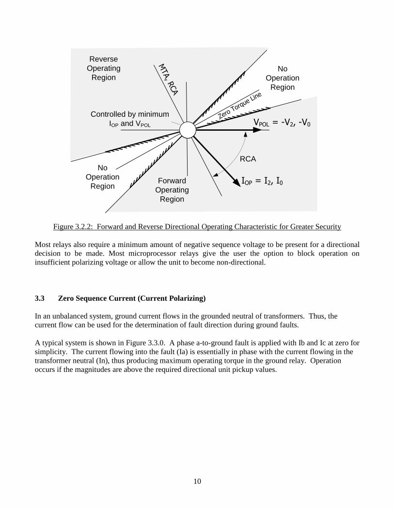
Figure 3.2.2: Forward and Reverse Directional Operating Characteristic for Greater Security
Most relays also require a minimum amount of negative sequence voltage to be present for a directional
decision to be made. Most microprocessor relays give the user the option to block operation on
insufficient polarizing voltage or allow the unit to become non-directional.
3.3 Zero Sequence Current (Current Polarizing)
In an unbalanced system, ground current flows in the grounded neutral of transformers. Thus, the
current flow can be used for the determination of fault direction during ground faults.
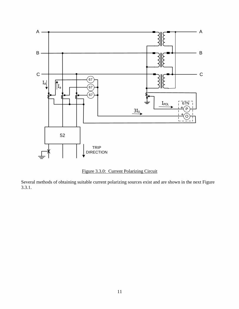
A typical system is shown in Figure 3.3.0. A phase a-to-ground fault is applied with Ib and Ic at zero for
simplicity. The current flowing into the fault (Ia) is essentially in phase with the current flowing in the
transformer neutral (In), thus producing maximum operating torque in the ground relay. Operation
occurs if the magnitudes are above the required directional unit pickup values.
11
67
67
67
P+
O+
67N
Ia
IA
3I0
52
TRIP
DIRECTIONX
A
B
C
A
B
C
IPOL
Figure 3.3.0: Current Polarizing Circuit
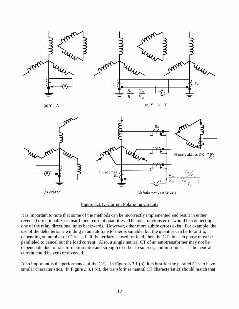
Several methods of obtaining suitable current polarizing sources exist and are shown in the next Figure
3.3.1.
12
P+
+P
+P
(a) U - D (b) U – D - U
(c) Zig-zag
+
(d) Auto – with D tertiary
P
RMRH
M
H
H
M
V
V
R
R
RM
RN
1-
M
H
M
H
N
M
VV
VV
R
R
+PVirtually always OK
OK at times
Figure 3.3.1: Current Polarizing Circuits
It is important to note that some of the methods can be incorrectly implemented and result in either
reversed directionality or insufficient current quantities. The most obvious error would be connecting
one of the relay directional units backwards. However, other more subtle errors exist. For example, the
use of the delta tertiary winding in an autotransformer is suitable, but the quantity can be Io or 3Io,
depending on number of CTs used. If the tertiary is used for load, then the CTs in each phase must be
paralleled to cancel out the load current. Also, a single neutral CT of an autotransformer may not be
dependable due to transformation ratio and strength of other Io sources, and in some cases the neutral
current could be zero or reversed.
Also important is the performance of the CTs. In Figure 3.3.1 (b), it is best for the parallel CTs to have
similar characteristics. In Figure 3.3.1 (d), the transformer neutral CT characteristics should match that
13
of the phase CTs. All CTs should have adequate accuracy rating where the effect of CT saturation is
minimized.
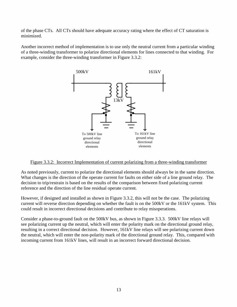
Another incorrect method of implementation is to use only the neutral current from a particular winding
of a three-winding transformer to polarize directional elements for lines connected to that winding. For
example, consider the three-winding transformer in Figure 3.3.2:
To 500kV line
ground relay
directional
elements
To 161kV line
ground relay
directional
elements
500kV 161kV
13kV
Figure 3.3.2: Incorrect Implementation of current polarizing from a three-winding transformer
As noted previously, current to polarize the directional elements should always be in the same direction.
What changes is the direction of the operate current for faults on either side of a line ground relay. The
decision to trip/restrain is based on the results of the comparison between fixed polarizing current
reference and the direction of the line residual operate current.
However, if designed and installed as shown in Figure 3.3.2, this will not be the case. The polarizing
current will reverse direction depending on whether the fault is on the 500kV or the 161kV system. This
could result in incorrect directional decisions and contribute to relay misoperations.
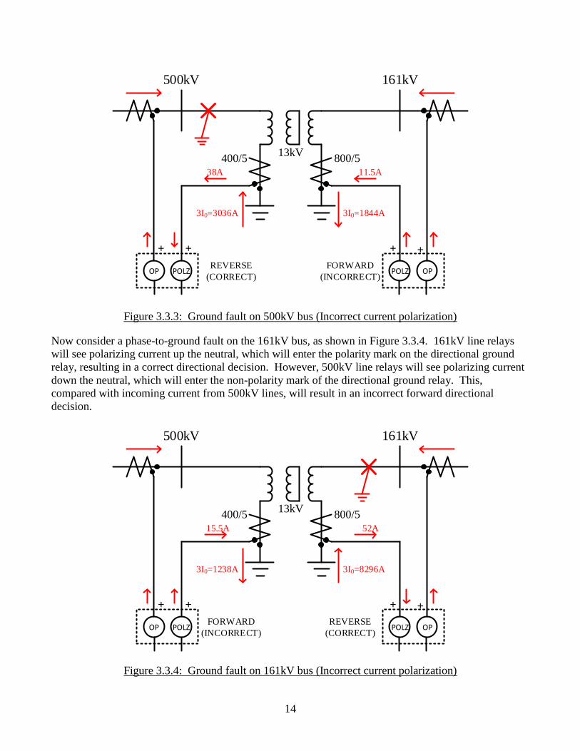
Consider a phase-to-ground fault on the 500kV bus, as shown in Figure 3.3.3. 500kV line relays will
see polarizing current up the neutral, which will enter the polarity mark on the directional ground relay,
resulting in a correct directional decision. However, 161kV line relays will see polarizing current down
the neutral, which will enter the non-polarity mark of the directional ground relay. This, compared with
incoming current from 161kV lines, will result in an incorrect forward directional decision.
14
REVERSE
(CORRECT)
500kV 161kV
OP POLZFORWARD
(INCORRECT)OPPOLZ
3I0=3036A 3I0=1844A
38A 11.5A
+ + + +
13kV800/5400/5
Figure 3.3.3: Ground fault on 500kV bus (Incorrect current polarization)
Now consider a phase-to-ground fault on the 161kV bus, as shown in Figure 3.3.4. 161kV line relays
will see polarizing current up the neutral, which will enter the polarity mark on the directional ground
relay, resulting in a correct directional decision. However, 500kV line relays will see polarizing current
down the neutral, which will enter the non-polarity mark of the directional ground relay. This,
compared with incoming current from 500kV lines, will result in an incorrect forward directional
decision.
REVERSE
(CORRECT)
500kV 161kV
OP POLZFORWARD
(INCORRECT)OPPOLZ
3I0=1238A 3I0=8296A
15.5A 52A
+ + + +
13kV800/5400/5
Figure 3.3.4: Ground fault on 161kV bus (Incorrect current polarization)
15
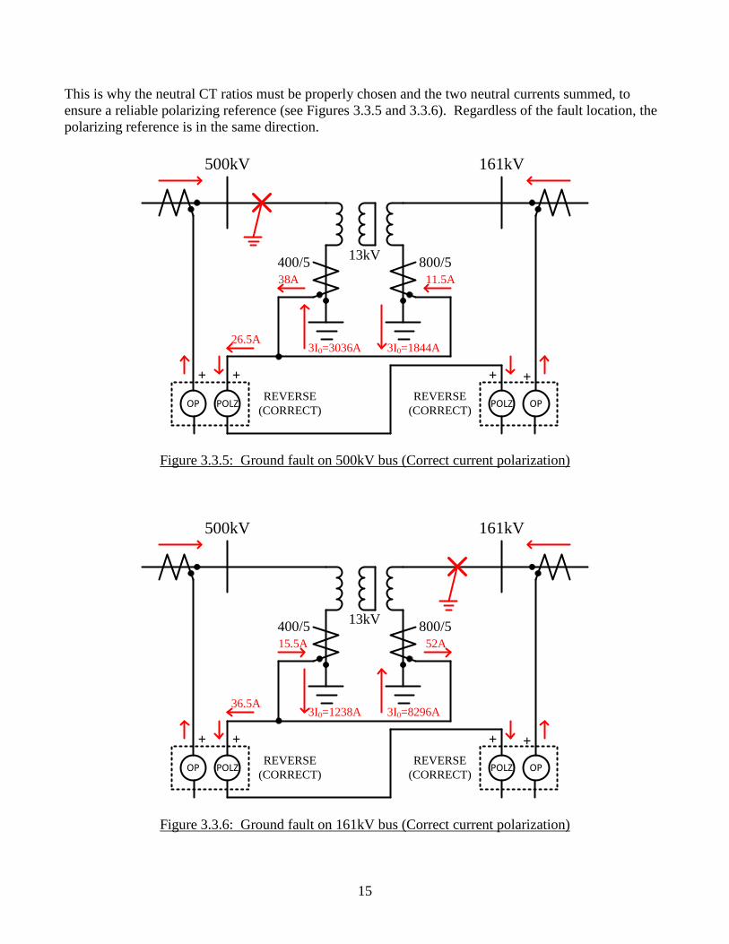
This is why the neutral CT ratios must be properly chosen and the two neutral currents summed, to
ensure a reliable polarizing reference (see Figures 3.3.5 and 3.3.6). Regardless of the fault location, the
polarizing reference is in the same direction.
REVERSE
(CORRECT)
500kV 161kV
OP POLZ OPPOLZ
3I0=3036A 3I0=1844A
38A 11.5A
+ + + +
13kV800/5400/5
26.5A
REVERSE
(CORRECT)
Figure 3.3.5: Ground fault on 500kV bus (Correct current polarization)
REVERSE
(CORRECT)
500kV 161kV
OP POLZ OPPOLZ
3I0=1238A 3I0=8296A
15.5A 52A
+ + + +
13kV800/5400/5
36.5A
REVERSE
(CORRECT)
Figure 3.3.6: Ground fault on 161kV bus (Correct current polarization)
16
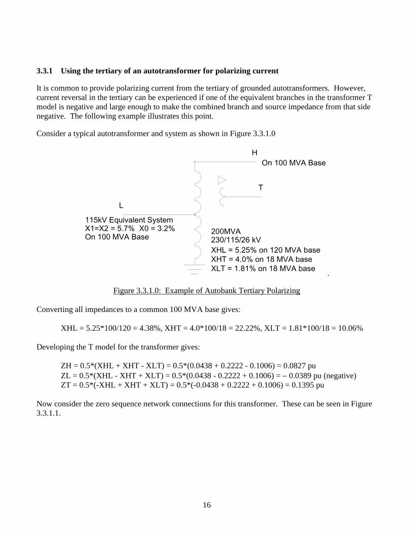
3.3.1 Using the tertiary of an autotransformer for polarizing current
It is common to provide polarizing current from the tertiary of grounded autotransformers. However,
current reversal in the tertiary can be experienced if one of the equivalent branches in the transformer T
model is negative and large enough to make the combined branch and source impedance from that side
negative. The following example illustrates this point.
Consider a typical autotransformer and system as shown in Figure 3.3.1.0
.
Figure 3.3.1.0: Example of Autobank Tertiary Polarizing
Converting all impedances to a common 100 MVA base gives:
XHL = 5.25*100/120 = 4.38%, XHT = 4.0*100/18 = 22.22%, XLT = 1.81*100/18 = 10.06%
Developing the T model for the transformer gives:
ZH = 0.5*(XHL + XHT - XLT) = 0.5*(0.0438 + 0.2222 - 0.1006) = 0.0827 pu
ZL = 0.5*(XHL - XHT + XLT) = 0.5*(0.0438 - 0.2222 + 0.1006) = - 0.0389 pu (negative)
ZT = 0.5*(-XHL + XHT + XLT) = 0.5*(-0.0438 + 0.2222 + 0.1006) = 0.1395 pu
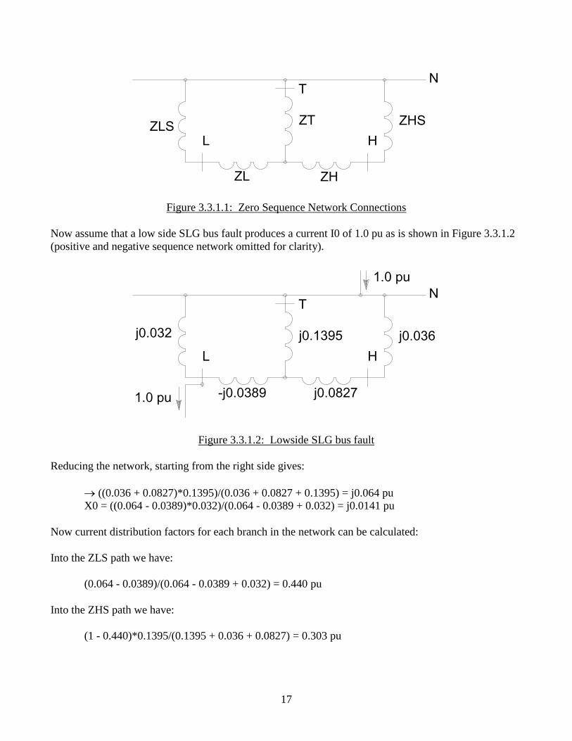
Now consider the zero sequence network connections for this transformer. These can be seen in Figure
3.3.1.1.
L
H
T
115kV Equivalent SystemX1=X2 = 5.7% X0 = 3.2%On 100 MVA Base
On 100 MVA Base
200MVA230/115/26 kV
XHL = 5.25% on 120 MVA base
XHT = 4.0% on 18 MVA base
XLT = 1.81% on 18 MVA base
17
Figure 3.3.1.1: Zero Sequence Network Connections
Now assume that a low side SLG bus fault produces a current I0 of 1.0 pu as is shown in Figure 3.3.1.2
(positive and negative sequence network omitted for clarity).
Figure 3.3.1.2: Lowside SLG bus fault
Reducing the network, starting from the right side gives:
((0.036 + 0.0827)*0.1395)/(0.036 + 0.0827 + 0.1395) = j0.064 pu
X0 = ((0.064 - 0.0389)*0.032)/(0.064 - 0.0389 + 0.032) = j0.0141 pu
Now current distribution factors for each branch in the network can be calculated:
Into the ZLS path we have:
(0.064 - 0.0389)/(0.064 - 0.0389 + 0.032) = 0.440 pu
Into the ZHS path we have:
(1 - 0.440)*0.1395/(0.1395 + 0.036 + 0.0827) = 0.303 pu
L H
TN
ZH
ZHS
ZL
ZLS ZT
L H
TN
j0.0827
j0.036
-j0.0389
j0.032
1.0 pu
1.0 pu
j0.1395
18
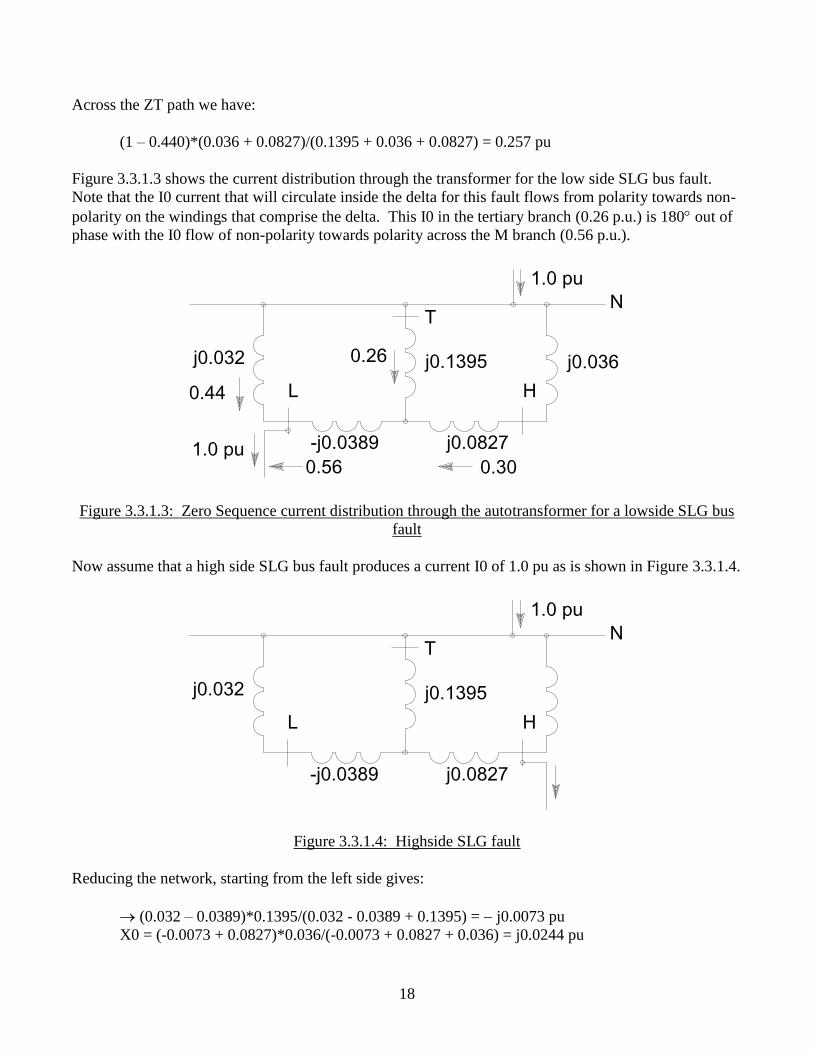
Across the ZT path we have:
(1 – 0.440)*(0.036 + 0.0827)/(0.1395 + 0.036 + 0.0827) = 0.257 pu
Figure 3.3.1.3 shows the current distribution through the transformer for the low side SLG bus fault.
Note that the I0 current that will circulate inside the delta for this fault flows from polarity towards non-
polarity on the windings that comprise the delta. This I0 in the tertiary branch (0.26 p.u.) is 180 out of
phase with the I0 flow of non-polarity towards polarity across the M branch (0.56 p.u.).
Figure 3.3.1.3: Zero Sequence current distribution through the autotransformer for a lowside SLG bus
fault
Now assume that a high side SLG bus fault produces a current I0 of 1.0 pu as is shown in Figure 3.3.1.4.
Figure 3.3.1.4: Highside SLG fault
Reducing the network, starting from the left side gives:
(0.032 – 0.0389)*0.1395/(0.032 - 0.0389 + 0.1395) = - j0.0073 pu
X0 = (-0.0073 + 0.0827)*0.036/(-0.0073 + 0.0827 + 0.036) = j0.0244 pu
L H
TN
j0.0827
j0.036
-j0.0389
j0.032
1.0 pu
1.0 pu
j0.1395
0.300.56
0.26
0.44
L H
TN
j0.0827-j0.0389
j0.032
1.0 pu
j0.1395
19
Now current distribution factors for each branch in the network can be calculated:
Into the ZHS path we have:
(-0.0073 + 0.0827)/(-0.0073 + 0.0827 + 0.036) = 0.677 pu
Into the ZLS path we have:
(1-0.677)*0.1395/(0.1395 + 0.032 - 0.0389) = 0.340 pu
Across the ZT path we have:
(1-0.677)*(0.032 - 0.0389)/(0.1395 + 0.032 - 0.0389) = - 0.0168 pu
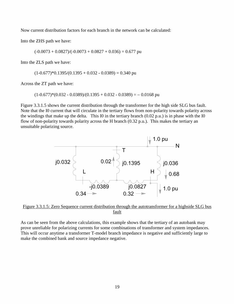
Figure 3.3.1.5 shows the current distribution through the transformer for the high side SLG bus fault.
Note that the I0 current that will circulate in the tertiary flows from non-polarity towards polarity across
the windings that make up the delta. This I0 in the tertiary branch (0.02 p.u.) is in phase with the I0
flow of non-polarity towards polarity across the H branch (0.32 p.u.). This makes the tertiary an
unsuitable polarizing source.
Figure 3.3.1.5: Zero Sequence current distribution through the autotransformer for a highside SLG bus
fault
As can be seen from the above calculations, this example shows that the tertiary of an autobank may
prove unreliable for polarizing currents for some combinations of transformer and system impedances.
This will occur anytime a transformer T-model branch impedance is negative and sufficiently large to
make the combined bank and source impedance negative.
L H
TN
j0.0827
j0.036
-j0.0389
j0.032
1.0 pu
1.0 pu
j0.1395
0.320.34
0.02
0.68
20
3.3.2 Specifying Polarizing CT Ratio
Current transformer ratios are selected to provide adequate current to operate the connected relays under
minimum conditions, supply the complete circuit burden, and not allow excessive currents for a
maximum fault. Where two or more current polarizing sources are used, the CT ratios should be
selected to provide approximately equal secondary currents from each source (not all identical CT
ratios) so that when one transformer is out of service the remaining polarizing current is adequate.
Typical steps for specifying CT used for polarizing are:
I. Find fault currents:
a. Minimum Remote end fault current I (min) under different contingencies at local
substation.
b. Maximum fault current I(max) under different contingencies at local substation
II. CT ratio selection:
a. Single CT source such as delta-wye transformer, autotransformer (neutral or tertiary
winding)
i. Select CT ratio such that minimum CT secondary current is equal or greater than
the relay minimum pickup (typically 0.5 amps), and also make sure that CT does
not saturate for I (max) fault current.
b. Two CTs such as wye-wye-delta transformer
i. The LV and HV CT neutral ratio should be inversely proportional to transformer
winding ratio
ii. Select the HV CT neutral (CTHvn) or LV CT neutral (CTLvn) ratio such that
minimum CT secondary current is equal or greater than the relay minimum
pickup (typically 0.5 amps), and also make sure that CT does not saturate for I
(max) fault current
3.4 Dual Polarizing, combination of zero sequence voltage and zero sequence current
Dual polarizing describes the application where the residual ground current 3I0 measured at the relay is
polarized by zero sequence voltage, -3V0, measured at the relay and a zero sequence current, IPol,
measured at a grounding transformer. This application is desirable because polarizing current, IPol, from
the transformer, if measured correctly (refer to Section 3.3), generally provides much more sensitivity to
remote faults than does polarizing voltage, -3V0. Polarizing voltage is adaptively used in the event
when the transformer providing the polarizing current is removed from service, i.e. IPol = 0.
21
Zero Sequence Voltage Polarized
Directional Ground Fault Function
-3V0 (Polarizing)
a = Maximum Torque Angle
Forward Operating
Region
Reverse Operating
Region
90°- a
Zero Torque Line
Max T
orq
ue L
ine
Operating Sensitivity Minimum Levels Non-operating
Region
3I0 (Operating)
Transformer Zero Sequence Current Polarized
Directional Ground Fault Function
Forward Operating
Region
Reverse Operating
Region
Zero Torque Line
Max T
orq
ue L
ine
Operating Sensitivity Minimum Levels
3I0 (Operating)
Ipol (Polarizing)
Non-operating
Region
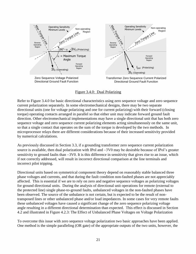
Figure 3.4.0: Dual Polarizing
Refer to Figure 3.4.0 for basic directional characteristics using zero sequence voltage and zero sequence
current polarization separately. In some electromechanical designs, there may be two separate
directional units (one for voltage polarizing and one for current polarizing) with their forward (closing
torque) operating contacts arranged in parallel so that either unit may indicate forward ground fault
direction. Other electromechanical implementations may have a single directional unit that has both zero
sequence voltage and zero sequence current polarizing elements acting simultaneously on the same unit,
so that a single contact that operates on the sum of the torque is developed by the two methods. In
microprocessor relays there are different considerations because of their increased sensitivity provided
by numerical calculations.
As previously discussed in Section 3.3, if a grounding transformer zero sequence current polarization
source is available, then dual polarization with IPol and -3V0 may be desirable because of IPol’s greater
sensitivity to ground faults than -3V0. It is this difference in sensitivity that gives rise to an issue, which
if not correctly addressed, will result in incorrect directional comparison at the line terminals and
incorrect pilot tripping.
Directional units based on symmetrical component theory depend on reasonably stable balanced three
phase voltages and currents, and that during the fault condition non-faulted phases are not appreciably
affected. This is essential if we are to rely on zero and negative sequence voltages as polarizing voltages
for ground directional units. During the analysis of directional unit operations for remote (external to
the protected line) single phase-to-ground faults, unbalanced voltages in the non-faulted phases have
been observed. The source of the unbalance is not certain, but is expected to be the result of non-
transposed lines or other unbalanced phase and/or load impedances. In some cases for very remote faults
these unbalanced voltages have caused a significant change of the zero sequence polarizing voltage
angle resulting in a different directional determination than expected. This effect is discussed in Section
4.2 and illustrated in Figure 4.2.3: The Effect of Unbalanced Phase Voltages on Voltage Polarization
To overcome this issue with zero sequence voltage polarization two basic approaches have been applied.
One method is the simple paralleling (OR gate) of the appropriate outputs of the two units, however, the
22
voltage polarizing unit is blocked if polarizing current is available. The voltage unit will only operate if
polarizing current is not available, which is generally determined by setting and indicates that the
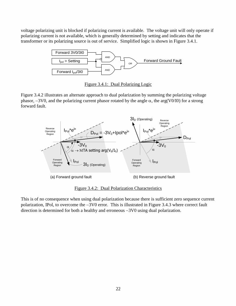
transformer or its polarizing source is out of service. Simplified logic is shown in Figure 3.4.1.
Forward 3V0/3I0
Forward Ipol/3I0
Ipol > Setting Forward Ground FaultAND
OR
AND
Figure 3.4.1: Dual Polarizing Logic
Figure 3.4.2 illustrates an alternate approach to dual polarization by summing the polarizing voltage
phasor, -3V0, and the polarizing current phasor rotated by the angle a, the arg(V0/I0) for a strong
forward fault.
(a) Forward ground fault (b) Reverse ground fault
DPol = -3V0+Ipol*ejα
-3V0
a MTA setting arg(V0/I0)
3I0 (Operating)IPol
IPol*ejα
a
Forward
Operating
Region
Reverse
Operating
Region
DPol
-3V0a
3I0 (Operating)
IPol
IPol*ejα
Forward
Operating
Region
Reverse
Operating
Region
Figure 3.4.2: Dual Polarization Characteristics
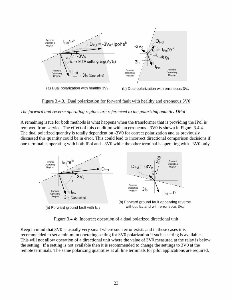
This is of no consequence when using dual polarization because there is sufficient zero sequence current
polarization, IPol, to overcome the -3V0 error. This is illustrated in Figure 3.4.3 where correct fault
direction is determined for both a healthy and erroneous -3V0 using dual polarization.
23
DPol = -3V0+Ipol*ejα
-3V0
a MTA setting arg(V0/I0)
3I0 (Operating)IPol
IPol*ejα
a
DPol
-3V0
3I0IPol
IPol*ejα
a
(a) Dual polarization with healthy 3V0
Forward
Operating
Region
(b) Dual polarization with erroneous 3V0
MTA
Reverse
Operating
Region
Forward
Operating
Region
Reverse
Operating
Region
Figure 3.4.3. Dual polarization for forward fault with healthy and erroneous 3V0
The forward and reverse operating regions are referenced to the polarizing quantity DPol
A remaining issue for both methods is what happens when the transformer that is providing the IPol is
removed from service. The effect of this condition with an erroneous -3V0 is shown in Figure 3.4.4.
The dual polarized quantity is totally dependent on -3V0 for correct polarization and as previously
discussed this quantity could be in error. This could lead to incorrect directional comparison decisions if
one terminal is operating with both IPol and -3V0 while the other terminal is operating with -3V0 only.
(a) Forward ground fault with IPol
DPol
-3V0a
3I0 (Operating)
IPol
IPol*ejα
Forward
Operating
Region
Reverse
Operating
Region DPol = -3V0
3I0IPol = 0
a
(b) Forward ground fault appearing reverse
without IPol and with erroneous 3V0
MT
AForward
Operating
Region
Reverse
Operating
Region
Figure 3.4.4: Incorrect operation of a dual polarized directional unit
Keep in mind that 3V0 is usually very small where such error exists and in these cases it is
recommended to set a minimum operating setting for 3V0 polarization if such a setting is available.
This will not allow operation of a directional unit where the value of 3V0 measured at the relay is below
the setting. If a setting is not available then it is recommended to change the settings to 3V0 at the
remote terminals. The same polarizing quantities at all line terminals for pilot applications are required.
24
3.5 Negative and Zero Sequence Impedance
A traditional compensated negative sequence directional element has a torque equation as shown in
equation 1 below.
Eq. 1
Where: V2 = Negative sequence voltage
I2 = Negative sequence current
ZLine2 = Negative sequence line impedance
= Compensation factor
* = Conjugate
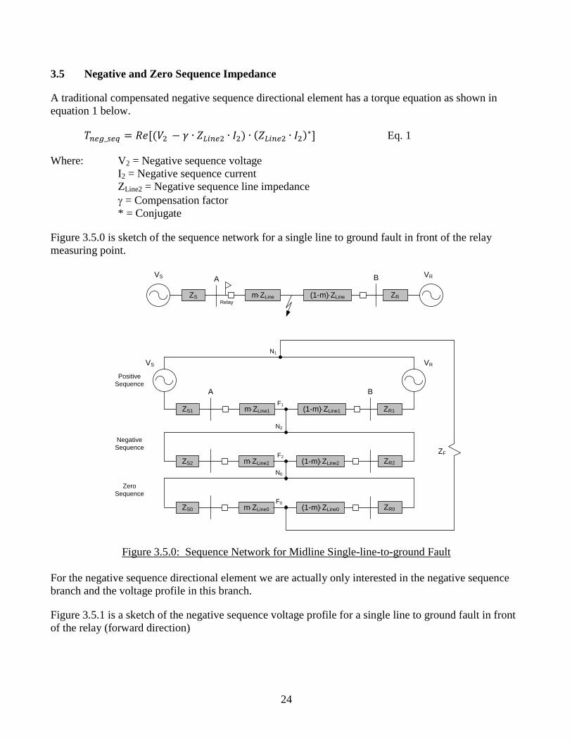
Figure 3.5.0 is sketch of the sequence network for a single line to ground fault in front of the relay
measuring point.
A B
ZS
VS
m×ZLine (1-m)×ZLine
VR
ZR
A B
ZS1
VS
m×ZLine1 (1-m)×ZLine1
VR
ZR1
ZS2 m×ZLine2 (1-m)×ZLine2 ZR2
ZS0 m×ZLine0 (1-m)×ZLine0 ZR0
N1
F1
F2
N2
N0
F0
Positive
Sequence
Negative
Sequence
Zero
Sequence
Relay
ZF
Figure 3.5.0: Sequence Network for Midline Single-line-to-ground Fault
For the negative sequence directional element we are actually only interested in the negative sequence
branch and the voltage profile in this branch.
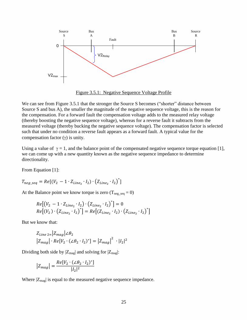
Figure 3.5.1 is a sketch of the negative sequence voltage profile for a single line to ground fault in front
of the relay (forward direction)
25
V2max
Source
S
Source
R
Bus
A
Bus
B
V2Relay
Fault
0
Figure 3.5.1: Negative Sequence Voltage Profile
We can see from Figure 3.5.1 that the stronger the Source S becomes (“shorter” distance between
Source S and bus A), the smaller the magnitude of the negative sequence voltage, this is the reason for
the compensation. For a forward fault the compensation voltage adds to the measured relay voltage
(thereby boosting the negative sequence voltage), whereas for a reverse fault it subtracts from the
measured voltage (thereby bucking the negative sequence voltage). The compensation factor is selected
such that under no condition a reverse fault appears as a forward fault. A typical value for the
compensation factor () is unity.
Using a value of = 1, and the balance point of the compensated negative sequence torque equation [1],
we can come up with a new quantity known as the negative sequence impedance to determine
directionality.
From Equation [1]:
(
)
At the Balance point we know torque is zero (Tneg_seq = 0)
[( ) (
) ]
[ ( )
] [
( )
]
But we know that:
| |
| | | |
| |
Dividing both side by |Zmag| and solving for |Zmag|:
| |
| |
Where |Zmag| is equal to the measured negative sequence impedance.
26
Note, zero sequence impedance is obtained similarly, utilizing the zero sequence components and the
zero sequence line impedance.
3.6 Virtual polarization
A ground fault protection scheme requires that a local residual current is compared to a local polarizing
voltage, and depending on the relative angular displacement of the two vectors, a forward or reverse
decision can be made. The ground fault relay operation is only reliable if there is a sufficient polarizing
quantity that is greater than that which could be generated by equipment tolerances or load unbalance.
This is difficult to guarantee when ground fault protection by its nature is applied to detect high
resistance faults of 50 to100’s of ohms. This will often generate negligible sequence component
quantities that are used by traditional relays.
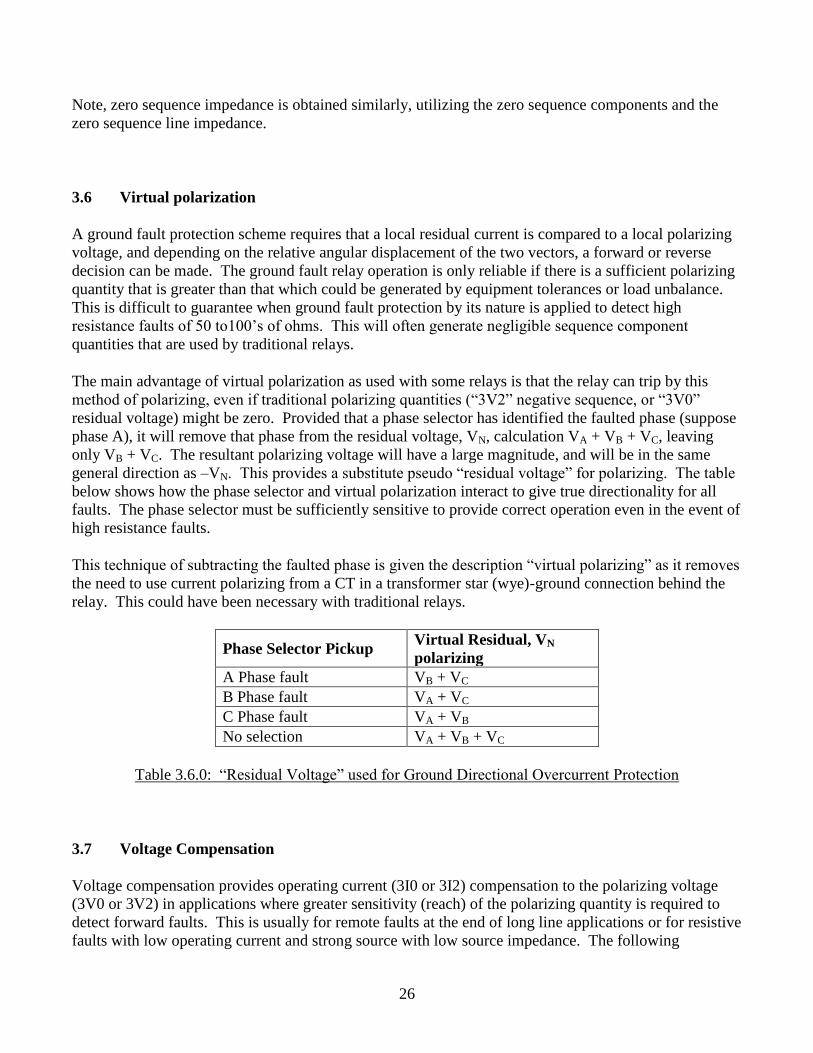
The main advantage of virtual polarization as used with some relays is that the relay can trip by this
method of polarizing, even if traditional polarizing quantities (“3V2” negative sequence, or “3V0”
residual voltage) might be zero. Provided that a phase selector has identified the faulted phase (suppose
phase A), it will remove that phase from the residual voltage, VN, calculation VA + VB + VC, leaving
only VB + VC. The resultant polarizing voltage will have a large magnitude, and will be in the same
general direction as –VN. This provides a substitute pseudo “residual voltage” for polarizing. The table
below shows how the phase selector and virtual polarization interact to give true directionality for all
faults. The phase selector must be sufficiently sensitive to provide correct operation even in the event of
high resistance faults.
This technique of subtracting the faulted phase is given the description “virtual polarizing” as it removes
the need to use current polarizing from a CT in a transformer star (wye)-ground connection behind the
relay. This could have been necessary with traditional relays.
Phase Selector Pickup Virtual Residual, VN
polarizing
A Phase fault VB + VC
B Phase fault VA + VC
C Phase fault VA + VB
No selection VA + VB + VC
Table 3.6.0: “Residual Voltage” used for Ground Directional Overcurrent Protection
3.7 Voltage Compensation
Voltage compensation provides operating current (3I0 or 3I2) compensation to the polarizing voltage
(3V0 or 3V2) in applications where greater sensitivity (reach) of the polarizing quantity is required to
detect forward faults. This is usually for remote faults at the end of long line applications or for resistive
faults with low operating current and strong source with low source impedance. The following
27
discussion focuses on zero-sequence polarizing, but can be similarly applied to negative sequence
polarized directional relays.
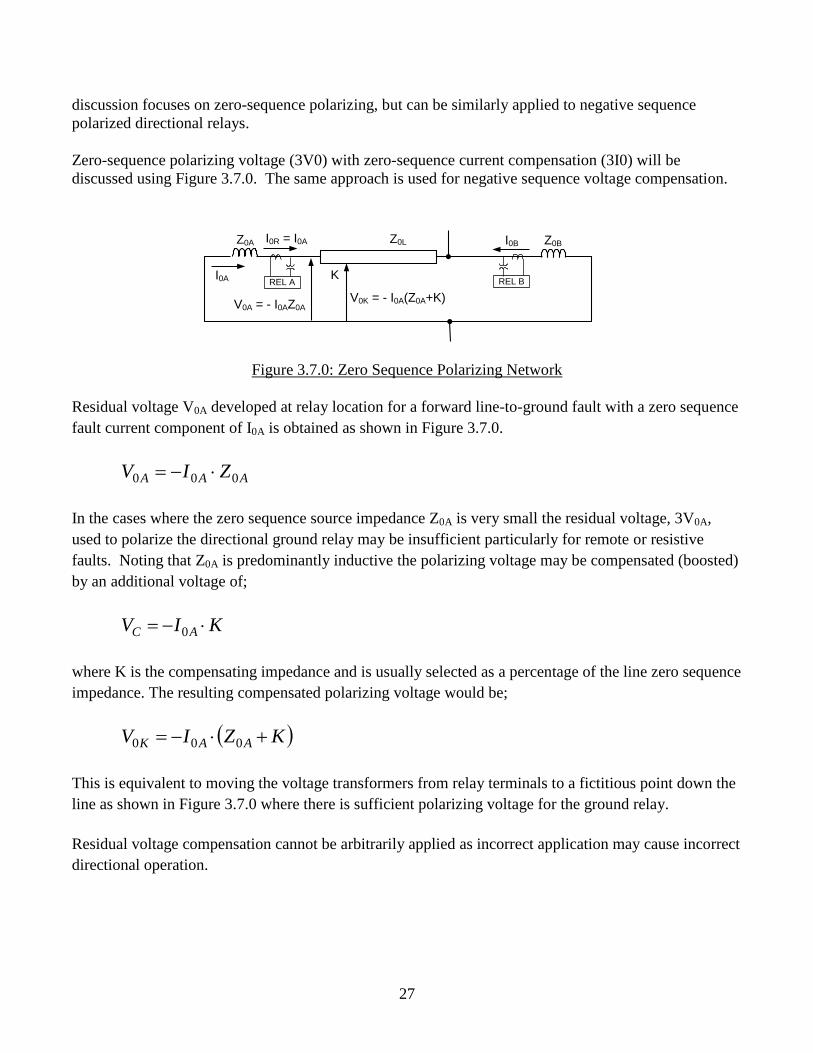
Zero-sequence polarizing voltage (3V0) with zero-sequence current compensation (3I0) will be
discussed using Figure 3.7.0. The same approach is used for negative sequence voltage compensation.
Z0LZ0A
REL A
Z0B
V0A = - I0AZ0A
REL B
I0BI0R = I0A
I0A
V0K = - I0A(Z0A+K)
K
Figure 3.7.0: Zero Sequence Polarizing Network
Residual voltage V0A developed at relay location for a forward line-to-ground fault with a zero sequence
fault current component of I0A is obtained as shown in Figure 3.7.0.
AAA ZIV 000 ×-
In the cases where the zero sequence source impedance Z0A is very small the residual voltage, 3V0A,
used to polarize the directional ground relay may be insufficient particularly for remote or resistive
faults. Noting that Z0A is predominantly inductive the polarizing voltage may be compensated (boosted)
by an additional voltage of;
KIV AC ×- 0
where K is the compensating impedance and is usually selected as a percentage of the line zero sequence
impedance. The resulting compensated polarizing voltage would be;
KZIV AAK ×- 000
This is equivalent to moving the voltage transformers from relay terminals to a fictitious point down the
line as shown in Figure 3.7.0 where there is sufficient polarizing voltage for the ground relay.
Residual voltage compensation cannot be arbitrarily applied as incorrect application may cause incorrect
directional operation.
28
Z0LZ0A
(a) Forward Fault
REL A
Z0B
V0A = - I0AZ0A
REL B
I0B
V0B
Z0LZ0A
(b) Reverse Fault
REL A
Z0B
V0A = - I0AZ0A
REL B
I0B
V0B
I0A
I0R = - I0B
I0R = I0A
I0A
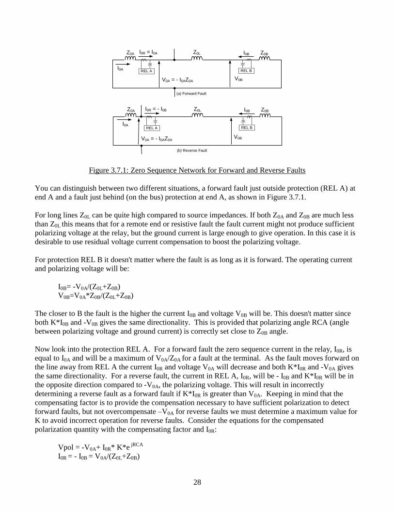
Figure 3.7.1: Zero Sequence Network for Forward and Reverse Faults
You can distinguish between two different situations, a forward fault just outside protection (REL A) at
end A and a fault just behind (on the bus) protection at end A, as shown in Figure 3.7.1.
For long lines Z0L can be quite high compared to source impedances. If both Z0A and Z0B are much less
than Z0L this means that for a remote end or resistive fault the fault current might not produce sufficient
polarizing voltage at the relay, but the ground current is large enough to give operation. In this case it is
desirable to use residual voltage current compensation to boost the polarizing voltage.
For protection REL B it doesn't matter where the fault is as long as it is forward. The operating current
and polarizing voltage will be:
I0B= -V0A/(Z0L+Z0B)
V0B=V0A*Z0B/(Z0L+Z0B)
The closer to B the fault is the higher the current I0B and voltage V0B will be. This doesn't matter since
both K*I0B and -V0B gives the same directionality. This is provided that polarizing angle RCA (angle
between polarizing voltage and ground current) is correctly set close to Z0B angle.
Now look into the protection REL A. For a forward fault the zero sequence current in the relay, I0R, is
equal to I0A and will be a maximum of V0A/Z0A for a fault at the terminal. As the fault moves forward on
the line away from REL A the current I0R and voltage V0A will decrease and both K*I0R and -V0A gives
the same directionality. For a reverse fault, the current in REL A, I0R, will be - I0B and K*I0R will be in
the opposite direction compared to -V0A, the polarizing voltage. This will result in incorrectly
determining a reverse fault as a forward fault if K*I0R is greater than V0A. Keeping in mind that the
compensating factor is to provide the compensation necessary to have sufficient polarization to detect
forward faults, but not overcompensate –V0A for reverse faults we must determine a maximum value for
K to avoid incorrect operation for reverse faults. Consider the equations for the compensated
polarization quantity with the compensating factor and I0R:
Vpol = -V0A+ I0R* K*e jRCA
I0R = - I0B = V0A/(Z0L+Z0B)
29
Combining the equations we get:
Vpol = -V0A+K*[ V0A/(Z0L+Z0B)]*e jRCA
Vpol = -V0A[1-K/(Z0L+Z0B)]e jRCA
In order to get correct directionality with the compensation factor for a reverse fault, K must be less than
(Z0L+Z0B), not considering the angle error. The source impedance Z0B might vary so the smallest value
provides best reliability. If Z0L is much greater than Z0B then the relation can be simplified into K<Z0L.
Considering that the reverse looking element may need to be more sensitive than a compensated relay at
the remote terminal, a common setting is K<0.4Z0L.
4.0 Investigate Application of Different Methods
4.1 Zero sequence mutually coupled lines
Recalling Basis of Zero Sequence Voltage Polarization
In an effectively grounded power system, the zero sequence voltage magnitude is highest at the point of
a single-line-to-ground fault and decreases as it is measured at points farther from the fault location. The
zero sequence fault current, normally defined as flowing from low V0 to high V0, will, therefore, be
defined as flowing in the direction of the single-line-to-ground fault. In a typical transmission system,
the angles of the impedance elements, representing the lines and transformers connecting the buses of
the zero sequence network do not vary a great deal, and can be collectively referred to in terms of a
characteristic angle " ". Assuming that a bolted, single-line-to-ground fault occurs somewhere on this
"typical" system, and any mutual induction between network connections can be neglected (or at least
minimized) the following generalities will tend to hold true:
The single-line-to-ground, zero sequence voltage (V0), at each of the buses in the network, will
be in the same phase angle vicinity with that existing at all the other buses; hence, the zero
sequence voltage can serve as a reference for establishing direction.
The zero sequence line current flow (3I0) in each impedance connection between the buses (each
defined as flowing from low V0 to high V0) will likewise be in the same phase angle vicinity
with that flowing in all the other connections.
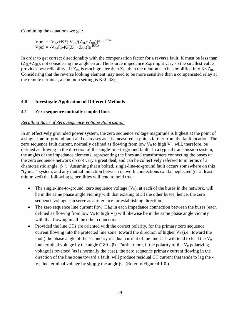
Provided the line CTs are oriented with the correct polarity, for the primary zero sequence
current flowing into the protected line zone, toward the direction of higher V0 (i.e., toward the
fault) the phase angle of the secondary residual current of the line CTs will tend to lead the V0
line terminal voltage by the angle (180 - β). Furthermore, if the polarity of the V0 polarizing
voltage is reversed (as is normally the case), the zero sequence primary current flowing in the
direction of the line zone toward a fault, will produce residual CT current that tends to lag the -
V0 line terminal voltage by simply the angle . (Refer to Figure 4.1.0.)
30
Figure 4.1.0: Zero Sequence Directional Characteristic
Recalling Basis of Zero Sequence Current Polarization
In most cases, zero sequence current sources, often available at the electrical nodes of transmission line
terminals, can be used as references for directional determination. This was described in detail in
Section 3.3. The section also warned that under certain circumstances, the I0 circulating in the tertiary
windings of certain autotransformers may not provide a reliable phasor reference.
Regardless of where a ground fault occurs on the "typical transmission system" (described previously in
the first paragraph of this Section 4.1), the phase angles of these zero sequence current source flows will
change very little, while the phase angle of the residual current received from the line CT's will differ by
approximately 180 for primary current flows toward faults on one side versus the other side of the CTs.
Recall that the zero sequence line current flows in each impedance connection of this "typical
transmission system" (when all are defined as flowing from low V0 to high V0) will be approximately
"in-phase" with one another. The polarity of both the line and the polarizing source CTs is normally
positioned so as to enable relay operation for fault current flows in the direction of the protected line
section. When this is the case, the phase angle of the residual current provided by the line CTs for
primary zero sequence current flows, that are toward faults in the direction of the line section, will be
very close to being "in-phase" with the polarizing current by small angles that are in the vicinity of 5 to
15.
Ramifications of Zero Sequence Mutual Coupling
90 °
0 ° 180 °
270 °
3I 0 (Toward Fault)
+
ABC
- V 0 (Polarizing)
V 0 (Polarizing)
180 ° - Reference Angle: Generator EMFs
31
As the effects of zero sequence mutual induction between the lines of a three phase, AC power system
network become more significant, the generalizations supporting both voltage and current, zero
sequence polarization (outlined above) become less reliable for ascertaining proper directionality. A
discussion of mutual induction is necessary in understanding why this is the case.
Mutual induction refers to the voltages that appear on the conductors of one circuit line due to the
currents flowing in the conductors of another. The ratio of the induced voltage in one line to the
inducing current of the other is defined as the mutual impedance between the two lines. Due to the angle
displacement characteristic of the positive and negative sequence phase currents, the associated
magnetic fields among the three phases experience a heavy cancelling effect, causing any positive or
negative sequence mutual coupling between circuits to be quite minimal (with total mutual impedance
values typically well less than 10% of the total line impedance). For this reason, mutual induction is
normally neglected for the positive and negative sequence components of current. The “in-phase” nature
of the zero sequence component of the phase currents, conversely produces a reinforcing magnetic
coupling effect, where the total mutual impedance can approach values as high as 50 to 70% of the total
line impedance. If two or more transmission lines share the same right-of-way for any significant length
of their total runs (whether they share the same tower structures, or not), they will likely have a
significant zero sequence mutual coupling. A set of zero sequence fault currents flowing in one line will
induce a set of zero sequence voltages within the other(s), and vice versa. Assuming the mutually
coupled lines are within the same electrical network, the mutually induced zero sequence voltage, in any
line, introduces a modification to the “network” solution of the current flow. (The “network” solution
refers to the voltage and current solution for the faulted system that does not account for any mutual
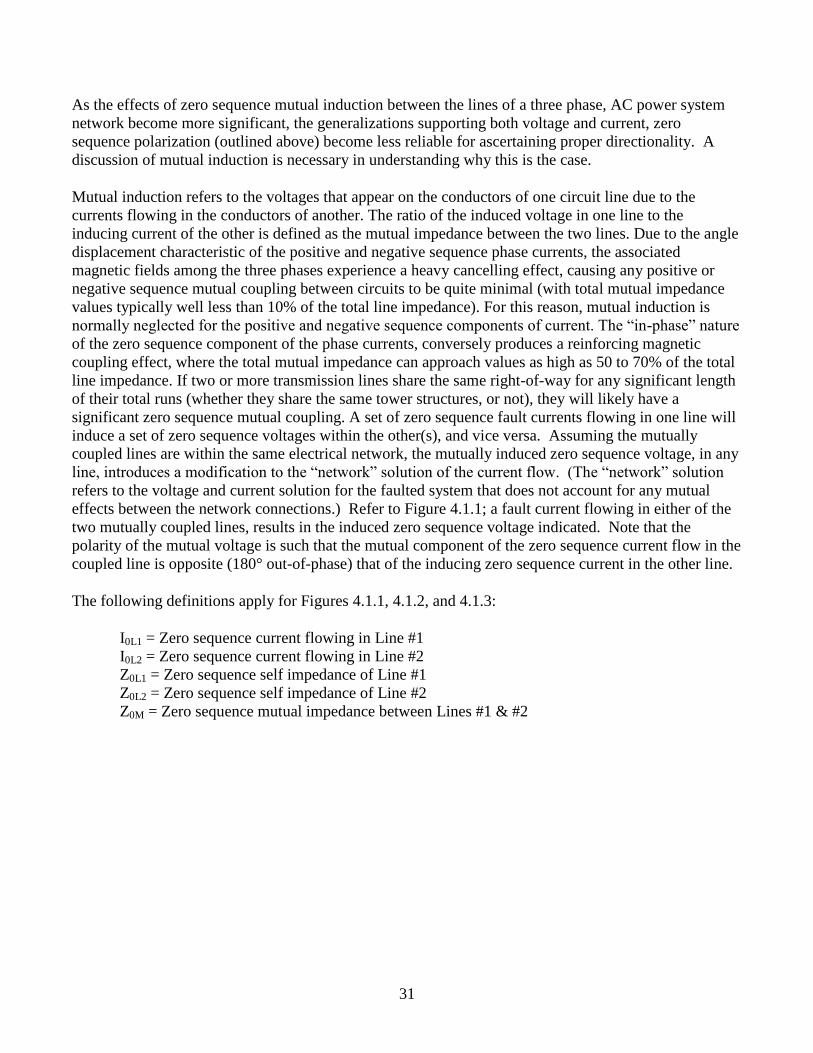
effects between the network connections.) Refer to Figure 4.1.1; a fault current flowing in either of the
two mutually coupled lines, results in the induced zero sequence voltage indicated. Note that the
polarity of the mutual voltage is such that the mutual component of the zero sequence current flow in the
coupled line is opposite (180° out-of-phase) that of the inducing zero sequence current in the other line.
The following definitions apply for Figures 4.1.1, 4.1.2, and 4.1.3:
I0L1 = Zero sequence current flowing in Line #1
I0L2 = Zero sequence current flowing in Line #2
Z0L1 = Zero sequence self impedance of Line #1
Z0L2 = Zero sequence self impedance of Line #2
Z0M = Zero sequence mutual impedance between Lines #1 & #2
32
Figure 4.1.1 Simple Representation for Zero-sequence Mutually Coupled Lines
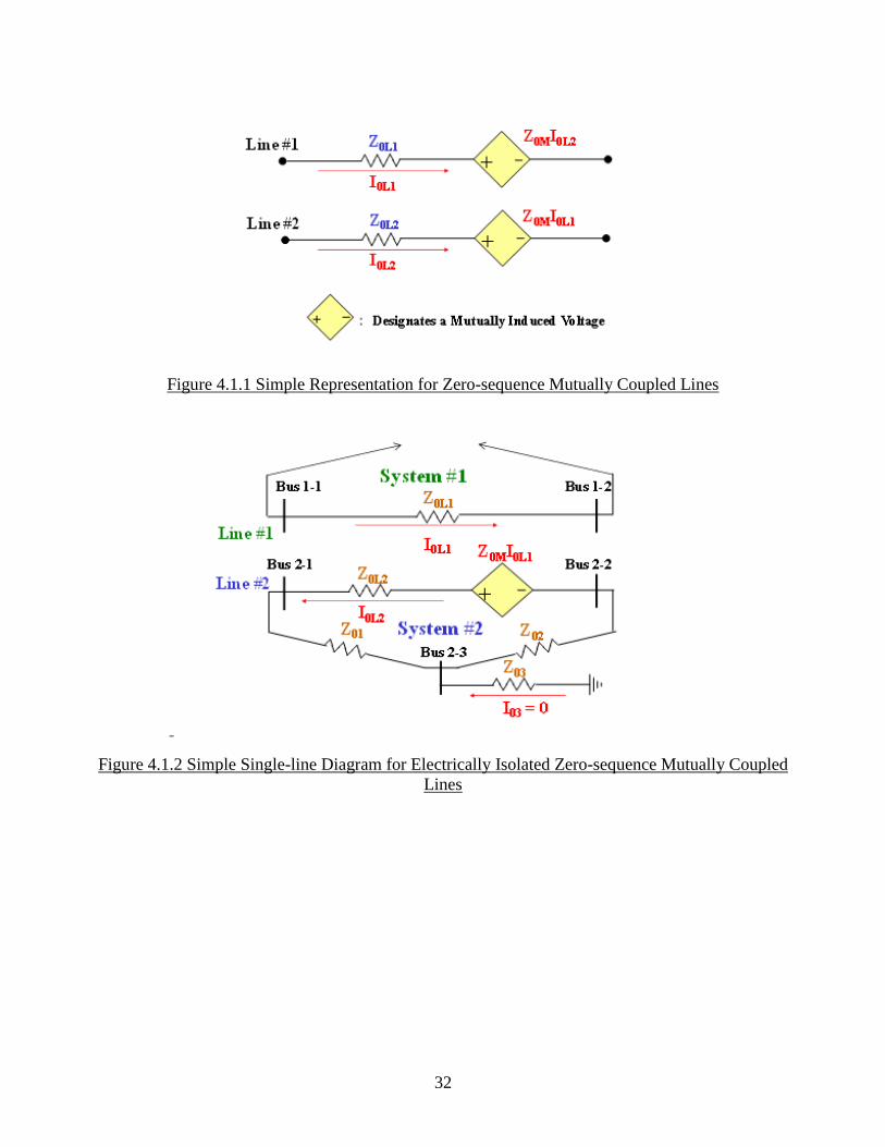
Figure 4.1.2 Simple Single-line Diagram for Electrically Isolated Zero-sequence Mutually Coupled
Lines
33
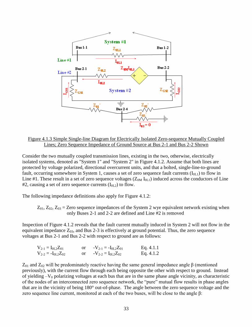
Figure 4.1.3 Simple Single-line Diagram for Electrically Isolated Zero-sequence Mutually Coupled
Lines; Zero Sequence Impedance of Ground Source at Bus 2-1 and Bus 2-2 Shown
Consider the two mutually coupled transmission lines, existing in the two, otherwise, electrically
isolated systems, denoted as "System 1" and "System 2" in Figure 4.1.2. Assume that both lines are
protected by voltage polarized, directional overcurrent units, and that a bolted, single-line-to-ground
fault, occurring somewhere in System 1, causes a set of zero sequence fault currents (I0L1) to flow in
Line #1. These result in a set of zero sequence voltages (Z0M I0L1) induced across the conductors of Line
#2, causing a set of zero sequence currents (I0L2) to flow.
The following impedance definitions also apply for Figure 4.1.2:
Z01, Z02, Z03 = Zero sequence impedances of the System 2 wye equivalent network existing when
only Buses 2-1 and 2-2 are defined and Line #2 is removed
Inspection of Figure 4.1.2 reveals that the fault current mutually induced in System 2 will not flow in the
equivalent impedance Z03, and Bus 2-3 is effectively at ground potential. Thus, the zero sequence
voltages at Bus 2-1 and Bus 2-2 with respect to ground are as follows:
V2-1 = I0L2Z01 or -V2-1 = -I0L2Z01 Eq. 4.1.1
V2-2 = -I0L2Z02 or -V2-2 = I0L2Z02 Eq. 4.1.2
Z01 and Z02 will be predominately reactive having the same general impedance angle β (mentioned
previously), with the current flow through each being opposite the other with respect to ground. Instead
of yielding –V0 polarizing voltages at each bus that are in the same phase angle vicinity, as characteristic
of the nodes of an interconnected zero sequence network, the “pure” mutual flow results in phase angles
that are in the vicinity of being 180° out-of-phase. The angle between the zero sequence voltage and the
zero sequence line current, monitored at each of the two buses, will be close to the angle β:
34
(-V2-1) - (I0L2) β Eq. 4.1.3
(-V2-2) - (-I0L2) β Eq. 4.1.4
Examination of equations 4.1.3 and 4.1.4 reveals that the voltage polarized, directional units at both
buses will indicate a fault within Line #2; with the Bus 2-1 unit determining a false direction, in this
case. A directional comparison protection scheme applied on Line #2 will, thus, undesirably operate for
a fault in the magnetically coupled System 1, provided the input quantities supplied to the directional
units have sufficient magnitude.
Now consider the mutually coupled transmission lines of the, otherwise, electrically isolated Systems 1
and 2, shown in Figure 4.1.3. Assume that the lines are now protected using current polarized,
directional overcurrent units, and the polarizing currents are obtained from Ground Sources #1 and #2,
located at buses 2-1 and 2-2, respectively.
These additional definitions apply for Figure 4.1.3
ZGS1 = Zero sequence impedance of Ground Source #1
ZGS2 = Zero sequence impedance of Ground Source #2
Z01', Z02', Z03' = Zero sequence impedances of the System 2 wye equivalent network existing
when only Buses 2-1 and 2-2 are defined and Line #2, Ground Source #1, and
Ground Source #2 are removed
Again, a bolted, single-phase-to-ground fault, occurring somewhere in System 1, causes a set of zero
sequence fault currents (I0L1) to flow in Line #1. A set of zero sequence voltages (Z0MI0L1) is again
induced across the conductors of line #2, causing a set of zero sequence currents (I0L2) to flow in Line
#2. As before, no current will flow in the equivalent impedance Z03', and Bus 2-4 will, effectively, be at
ground potential. Using current division, the following can be derived:
IGS1 = -I0L2Z01' / (Z01' + ZGS1) Eq. 4.1.5
IGS2 = I0L2Z02' / (Z02' + ZGS2) Eq. 4.1.6
As in the previous example, Z01, Z02, ZGS1, and ZGS2 will be predominately reactive having the same
general impedance angle β, with the current flow through each ground source being opposite the other.
Instead of yielding I0 polarizing currents at each ground source that are in the same phase angle vicinity,
as characteristic of those ground sources connected to the nodes of an interconnected zero sequence
network, this “pure” mutually induced flow results in phase angles that are in the vicinity of being 180°
out-of-phase. The ground source zero sequence current and the zero sequence line current, monitored at
each of the two buses, will be close to being in-phase:
( IGS1) (-I0L2) Eq. 4.1.7
( IGS2) (I0L2) Eq. 4.1.8
Equations 4.1.7 and 4.1.8 reveal that the current polarized, directional units at both buses will indicate a
fault within Line #2; with the Bus 2-1 unit determining a false direction, in this case. A directional
comparison protection scheme applied on Line #2 will, thus, undesirably operate for a fault in the
35
magnetically coupled System 1, provided the input quantities supplied to the directional units have
sufficient magnitude.
Summary
The previous examples illustrate the worst case situation for mutually coupled transmission lines: When
the fault current flowing through the directional comparison zone of a particular transmission line (for
an external fault) is due solely to the current induced by zero sequence mutual coupling, both the voltage
and current polarized directional units associated with the scheme will easily indicate a false direction -
resulting in an undesirable line trip. In an actual transmission system, however, lines are rarely both
completely mutually coupled and electrically isolated at the same time. Generally, the component of
zero sequence current flow in a magnetically coupled line that is actually due to the mutually induced
voltage has a much smaller effect on the resultant line zero sequence current than the electrical network
flows. (The normal network flows, recall, harmonize with the generalities supporting zero sequence
polarizing.) System configurations can exist, however, where mutual effects can detrimentally alter the
network flow enough to result in a false directional determination. As a precaution, when zero sequence
polarization is employed, false trip checks should be done for all lines which are mutually coupled with
other lines. If setting changes that would remedy the situation cannot be applied without violating the
normal protection, a different method of directional determination (such as negative sequence
polarizing) should be considered.
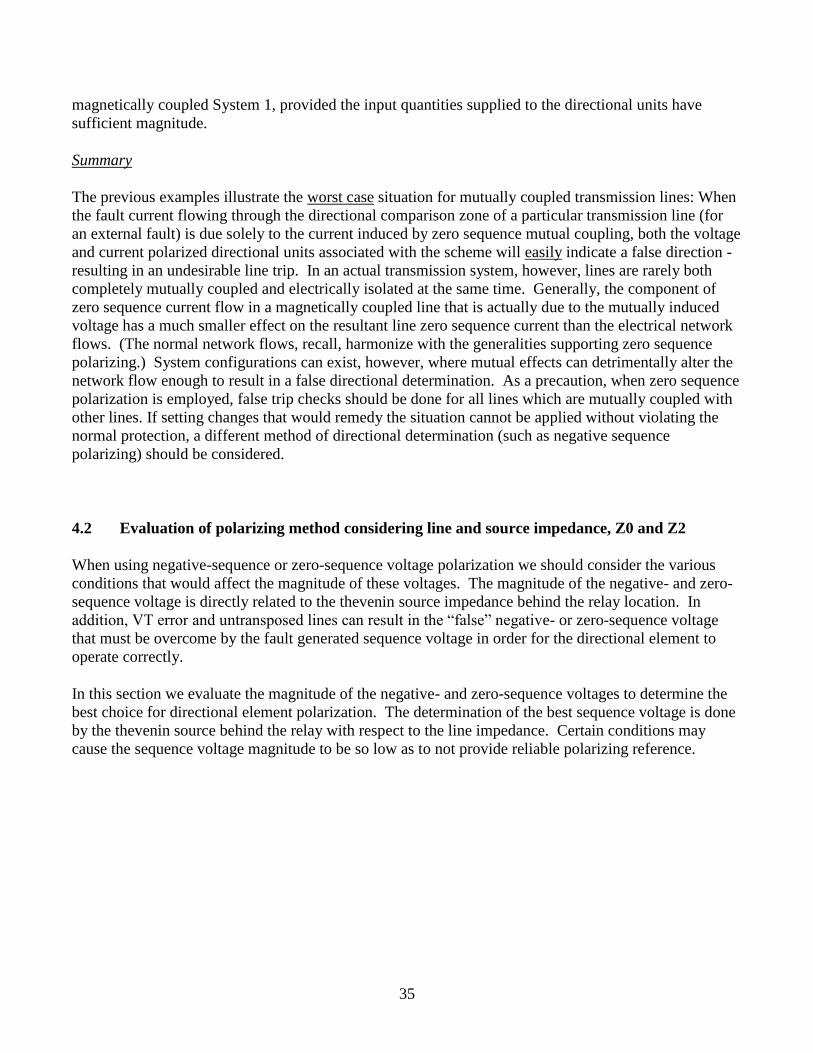
4.2 Evaluation of polarizing method considering line and source impedance, Z0 and Z2
When using negative-sequence or zero-sequence voltage polarization we should consider the various
conditions that would affect the magnitude of these voltages. The magnitude of the negative- and zero-
sequence voltage is directly related to the thevenin source impedance behind the relay location. In
addition, VT error and untransposed lines can result in the “false” negative- or zero-sequence voltage
that must be overcome by the fault generated sequence voltage in order for the directional element to
operate correctly.
In this section we evaluate the magnitude of the negative- and zero-sequence voltages to determine the
best choice for directional element polarization. The determination of the best sequence voltage is done
by the thevenin source behind the relay with respect to the line impedance. Certain conditions may
cause the sequence voltage magnitude to be so low as to not provide reliable polarizing reference.
36
RELAY
Z1S nZ1L Z1U(1-n)Z1L
VA1
IA1S
RELAY
Z2S nZ2L Z2U(1-n)Z2L
VA2
IA2S
RELAY
Z0S nZ0L Z0U(1-n)Z0L
VA0
IA0S
F
F
F
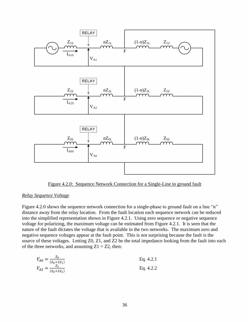
Figure 4.2.0: Sequence Network Connection for a Single-Line to ground fault
Relay Sequence Voltage
Figure 4.2.0 shows the sequence network connection for a single-phase to ground fault on a line “n”
distance away from the relay location. From the fault location each sequence network can be reduced
into the simplified representation shown in Figure 4.2.1. Using zero sequence or negative sequence
voltage for polarizing, the maximum voltage can be estimated from Figure 4.2.1. It is seen that the
nature of the fault dictates the voltage that is available in the two networks. The maximum zero and
negative sequence voltages appear at the fault point. This is not surprising because the fault is the
source of these voltages. Letting Z0, Z1, and Z2 be the total impedance looking from the fault into each
of the three networks, and assuming Z1 = Z2, then:
Eq. 4.2.1
Eq. 4.2.2
37
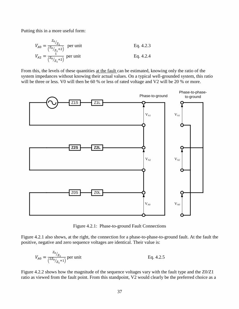
Putting this in a more useful form:
⁄
(
⁄ )
per unit Eq. 4.2.3
(
⁄ )
per unit Eq. 4.2.4
From this, the levels of these quantities at the fault can be estimated, knowing only the ratio of the
system impedances without knowing their actual values. On a typical well-grounded system, this ratio
will be three or less. V0 will then be 60 % or less of rated voltage and V2 will be 20 % or more.
Z1S Z1L
Z2S Z2L
Z0S Z0L
VA1
VA2
VA0
Phase-to-ground
VA1
VA2
VA0
Phase-to-phase-
to-ground
Figure 4.2.1: Phase-to-ground Fault Connections
Figure 4.2.1 also shows, at the right, the connection for a phase-to-phase-to-ground fault. At the fault the
positive, negative and zero sequence voltages are identical. Their value is:
⁄
(
⁄ )
per unit Eq. 4.2.5
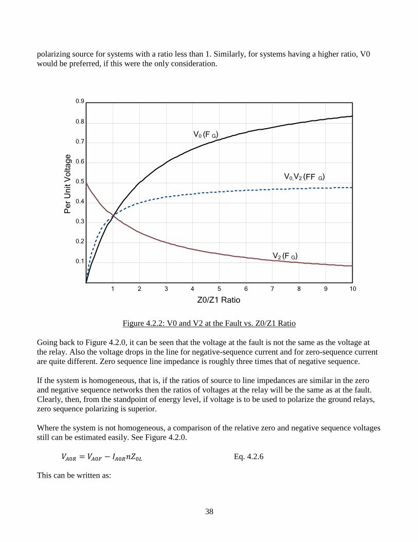
Figure 4.2.2 shows how the magnitude of the sequence voltages vary with the fault type and the Z0/Z1
ratio as viewed from the fault point. From this standpoint, V2 would clearly be the preferred choice as a
38
polarizing source for systems with a ratio less than 1. Similarly, for systems having a higher ratio, V0
would be preferred, if this were the only consideration.
1 2 3 4 5 6 7 8 9 10
0.1
0.2
0.3
0.4
0.5
0.6
0.7
0.8
0.9
Z0/Z1 Ratio
Pe
r U
nit V
olta
ge
V0 ( G)F
V2 ( G)F
V0,V2 ( G)FF
Figure 4.2.2: V0 and V2 at the Fault vs. Z0/Z1 Ratio
Going back to Figure 4.2.0, it can be seen that the voltage at the fault is not the same as the voltage at
the relay. Also the voltage drops in the line for negative-sequence current and for zero-sequence current
are quite different. Zero sequence line impedance is roughly three times that of negative sequence.
If the system is homogeneous, that is, if the ratios of source to line impedances are similar in the zero
and negative sequence networks then the ratios of voltages at the relay will be the same as at the fault.
Clearly, then, from the standpoint of energy level, if voltage is to be used to polarize the ground relays,
zero sequence polarizing is superior.
Where the system is not homogeneous, a comparison of the relative zero and negative sequence voltages
still can be estimated easily. See Figure 4.2.0.
Eq. 4.2.6
This can be written as:
39
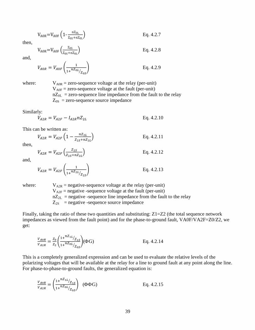
( -
) Eq. 4.2.7
then,
(
) Eq. 4.2.8
and,
(
⁄
) Eq. 4.2.9
where: VA0R = zero-sequence voltage at the relay (per-unit)
VA0F = zero-sequence voltage at the fault (per-unit)
nZ0L = zero-sequence line impedance from the fault to the relay
Z0S = zero-sequence source impedance
Similarly:
Eq. 4.2.10
This can be written as:
(
) Eq. 4.2.11
then,
(
) Eq. 4.2.12
and,
(
⁄
) Eq. 4.2.13
where: VA2R = negative-sequence voltage at the relay (per-unit)
VA2F = negative -sequence voltage at the fault (per-unit)
nZ2L = negative -sequence line impedance from the fault to the relay
Z2S = negative -sequence source impedance
Finally, taking the ratio of these two quantities and substituting: Z1=Z2 (the total sequence network
impedances as viewed from the fault point) and for the phase-to-ground fault, VA0F/VA2F=Z0/Z2, we
get:
(
⁄
⁄
)(G) Eq. 4.2.14
This is a completely generalized expression and can be used to evaluate the relative levels of the
polarizing voltages that will be available at the relay for a line to ground fault at any point along the line.
For phase-to-phase-to-ground faults, the generalized equation is:
(
⁄
⁄
) (G) Eq. 4.2.15
40
Note that these two equations apply, irrespective of what system components exist to the right of the
fault point and irrespective of the relative sequence-current distribution factors. Those other system
components will, of course, influence the total Z0 and Z1 values, but their ratio will not vary greatly.
From these two expressions above, it can be seen for long line applications that polarizing voltage level,
as a criterion, may favor zero-sequence voltage polarizing, because Z0L usually exceeds Z1L.
For short-line applications, the ratio of the sequence voltages at the relay will be more nearly that which
exists at the fault, thus favoring the use of zero-sequence voltage polarizing.
Polarizing Voltage Magnitude
Referring to Figure 4.2.0, it can be seen that the magnitude of the negative- or zero-sequence voltages
are directly proportional to the current and the source impedance behind the relay location. Therefore, it
can be seen that given a long line with a strong source behind the relay (Z2L >> Z2S or Z0L >> Z0S) the
negative or zero-sequence voltage at the relay location can be relatively small. Although the previous
analysis indicated that zero-sequence is a better choice for long line applications, we can see that it is
also dependent upon the strength of the source behind the relay.
When evaluating the choice of negative or zero-sequence voltage polarization for long lines there are
two factors that will influence the decision; the magnitude of the negative- or zero-sequence voltage at
the fault and the ratio of the negative- or zero-sequence lines impedance to the respective source
impedance behind the relay location. The magnitude of the sequence voltage at the fault can be
determined using Eq. 4.2.3 and Eq. 4.2.4 for the respective sequence voltage. The magnitude of the
voltage at the relay location can be determined from Eq. 4.2.9 and Eq. 4.2.13. Combing these equations
and recognizing that the critical fault location is going to be at the remote end of the line where n = 1
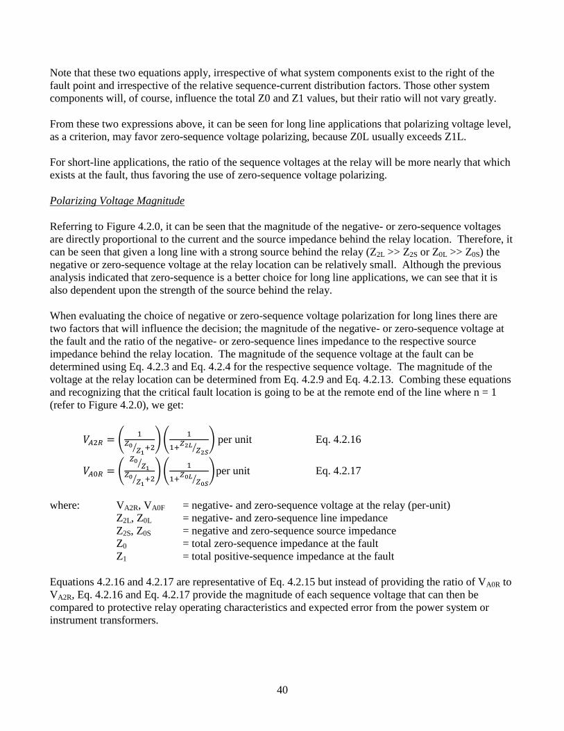
(refer to Figure 4.2.0), we get:
(
⁄ )(
⁄
) per unit Eq. 4.2.16
(
⁄
⁄ )(
⁄
) per unit Eq. 4.2.17
where: VA2R, VA0F = negative- and zero-sequence voltage at the relay (per-unit)
Z2L, Z0L = negative- and zero-sequence line impedance
Z2S, Z0S = negative and zero-sequence source impedance
Z0 = total zero-sequence impedance at the fault
Z1 = total positive-sequence impedance at the fault
Equations 4.2.16 and 4.2.17 are representative of Eq. 4.2.15 but instead of providing the ratio of VA0R to
VA2R, Eq. 4.2.16 and Eq. 4.2.17 provide the magnitude of each sequence voltage that can then be
compared to protective relay operating characteristics and expected error from the power system or
instrument transformers.
41
For example, if a protective relay requires a minimum negative-sequence voltage of 1V secondary, we
can check the magnitude of VA2R using Eq. 4.2.16 against this threshold from data obtained from a fault
study and the line parameters. If the voltage obtained from Eq. 4.2.16 is less than 1V secondary, then
negative-sequence polarization would not be a good choice for this application.
Sources of Error in calculating V2 and V0 – Untransposed Lines
Errors caused by untransposed lines can result in an erroneous negative- or zero-sequence voltage during
steady-state conditions. If these error voltages are greater than the fault generated voltages, then the
polarizing voltage could reverse resulting in an incorrect directional decision.
Lack of transpositions on long transmission lines causes the phase impedances to be unequal. Thus a
three-phase fault, for example, will generate zero and negative-sequence voltage drops. This, in turn,
causes zero and negative-sequence current flow that may be of sufficient magnitude to produce
undesirable operation of directional ground overcurrent relays. It is reasonable to attribute the following
problem to unequal phase impedances.
Directional units based on symmetrical component theory depend on reasonably stable balanced three
phase voltages and that during the fault condition, non-faulted phases are not appreciably affected. This
is essential if we are to rely on zero and negative sequence voltages as polarizing voltages for ground
directional units. During the analysis of directional unit operations for single phase-to-ground faults
unbalances in the non-faulted phases have been observed. The source of the unbalance is not certain, but
is expected to be the result of unbalanced phase impedances and loading. In some cases of low
sensitivity (very remote faults) these unbalanced voltages have caused a reversal of the polarizing
voltage resulting in incorrect directional sensing. This effect is illustrated in Figure 4.2.3.
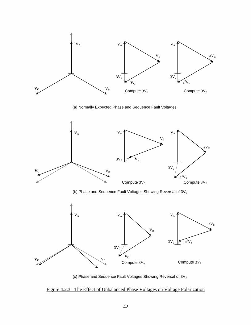
Figure 4.2.3(a) shows the expected phase and sequence voltages for a phase AG fault. The negative- and
zero-sequence voltages are graphically computed using the symmetrical component equations:
42
(a) Normally Expected Phase and Sequence Fault Voltages
(b) Phase and Sequence Fault Voltages Showing Reversal of 3V0
(c) Phase and Sequence Fault Voltages Showing Reversal of 3V2
VA
VBVC
VA VA
VA VA VA
VA VA VA
VC
VC
VC
VC
VC
VB
VB
VB
VB
VB
a2Vb
a2Vb
a2Vb
aVC
aVC
aVC
3V0
3V0
3V0
3V2
3V2
3V2
Compute 3V2
Compute 3V2
Compute 3V2Compute 3V0
Compute 3V0
Compute 3V0
Figure 4.2.3: The Effect of Unbalanced Phase Voltages on Voltage Polarization
43
Figure 4.2.3(b) shows the direction reversal of 3V0 where the phase angle between the unfaulted phases
is greater than 120. Figure 4.2.3(c) shows the direction reversal of 3V2 where the phase angle between
the unfaulted phases less than 120. This unbalance, although small, introduces enough effect on the
“expected" sequence voltage angle at these small values causing the incorrect directional sensing.
4.3 Combining multiple polarizing methods
Several methods exist for combining polarizing methods:
4.3.1 Dual zero-sequence polarizing
Both zero-sequence voltage and zero-sequence current are used. Different ways of implementing this
include:
Sum of torque developed using each method
If zero-sequence polarizing current is above a certain threshold (e.g., 0.5A secondary), only zero-
sequence current polarizing is used, neglecting any decision made or torque developed by the
zero-sequence voltage element. If the zero-sequence current is below the threshold, then the
zero-sequence voltage element is used.
4.3.2 Both negative and zero-sequence polarizing (preferential based on sensitivity thresholds)
Some relays have the capability of implementing zero-sequence voltage, zero-sequence current, and
negative sequence polarizing, giving preference to any order of the three, based on meeting sensitivity
thresholds.
Caution should be used when implementing such a scheme. If zero-sequence polarizing is an inadequate
method (say, due to mutual coupling), it generally should not be combined with negative-sequence
polarizing even if the relay provides that capability.
5.0 Other Considerations
5.1 Installation and verification tests of the directional elements
To avoid misoperation of ground relaying, polarizing circuits should be checked before the relays are
placed in service. Many utilities have testing guidelines on how to verify the polarizing methods.
Guidance can also be obtained from IEEE Std. C37.103 Guide for Differential and Polarizing Relay
Circuit Testing.
44
With the advent of microprocessor relays with digital oscillographic capability, another option may be
considered for polarizing methods using dual zero-sequence polarizing. It would be possible to initially
place a relay in-service with voltage polarizing only (zero or negative sequence), then examine the first
oscillographic record taken for a nearby phase-ground fault (in-service polarizing test). Since voltage
polarizing is determined internally, it should operate properly. Current polarizing connections to the
relay could be determined by examining the relay record and corrected if necessary. Then current
polarizing could be enabled. This method has been used in practice in a few locations due to the
difficulty in performing current polarizing tests, particularly at large generating stations.
5.2 Open pole conditions
5.2.1 Single pole open condition affecting an adjacent line [7], [8]
While the effects of a pole open are most noticeable on the line with the pole open it also presents a
concern for adjacent lines. Transmission lines using single-pole tripping invariably have pilot protection
schemes that allow both ends to know of the open pole condition. This allows those relays to disable
elements that may be susceptible to misoperation during the open pole condition. Relays on adjacent
lines do not have this luxury; as a result careful consideration should be given to the operation of
directional elements on these adjacent lines. Factors such as load flow, directional sensitivity, and
target resistive coverage will effect implementation. Due to the complexity of the problem some
solutions may be ineffective under different system conditions and desensitizing fault detectors to avoid
misoperation on the open-pole may reduce the resistive coverage to the point that these elements aren’t
particularly useful in the first place.
With modern communications capabilities it may be possible to allow traditional sensitive directional
ground TOC elements to remain operational, only being disabled when commanded from a local or
remote relay. This of course adds complexity which must be weighed against the perceived benefits.
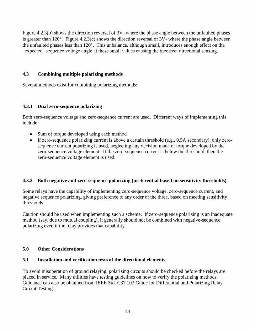
Below is an example of polarizing quantity under a single pole open condition for a SLG fault depicted
in the figures below:
Figure: 5.2.0: A Phase Pole Open; B Phase Single-Line-to-Ground at the Remote Bus
45
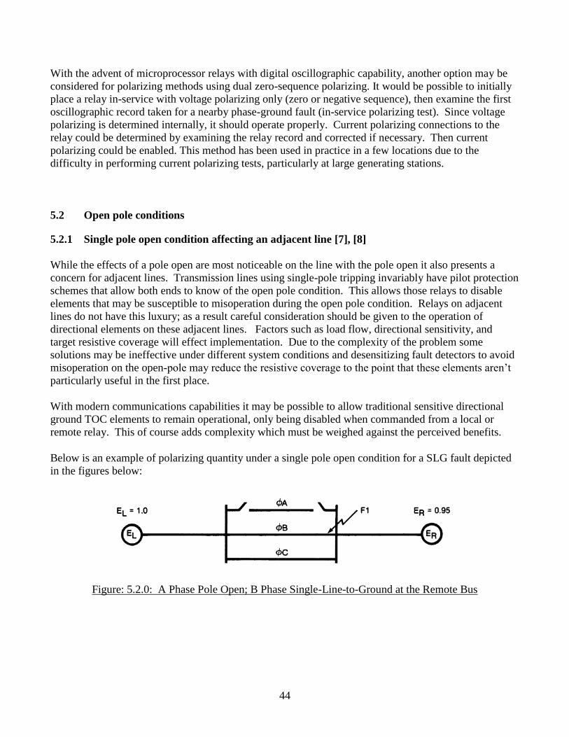
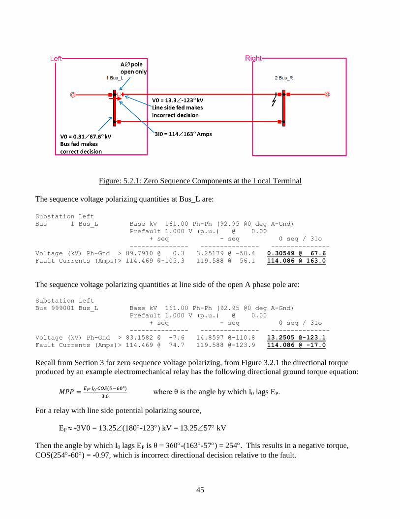
Figure: 5.2.1: Zero Sequence Components at the Local Terminal
The sequence voltage polarizing quantities at Bus_L are:
Substation Left
Bus 1 Bus_L Base kV 161.00 Ph-Ph (92.95 @0 deg A-Gnd)
Prefault 1.000 V (p.u.) @ 0.00
+ seq - seq 0 seq / 3Io
--------------- --------------- ---------------
Voltage (kV) Ph-Gnd > 89.7910 @ 0.3 3.25179 @ -50.4 0.30549 @ 67.6
Fault Currents (Amps)> 114.469 @-105.3 119.588 @ 56.1 114.086 @ 163.0
The sequence voltage polarizing quantities at line side of the open A phase pole are:
Substation Left
Bus 999001 Bus_L Base kV 161.00 Ph-Ph (92.95 @0 deg A-Gnd)
Prefault 1.000 V (p.u.) @ 0.00
+ seq - seq 0 seq / 3Io
--------------- --------------- ---------------
Voltage (kV) Ph-Gnd > 83.1582 @ -7.6 14.8597 @-110.8 13.2505 @-123.1
Fault Currents (Amps)> 114.469 @ 74.7 119.588 @-123.9 114.086 @ -17.0
Recall from Section 3 for zero sequence voltage polarizing, from Figure 3.2.1 the directional torque
produced by an example electromechanical relay has the following directional ground torque equation:
where θ is the angle by which I0 lags EP.
For a relay with line side potential polarizing source,
EP -3V0 = 13.25(180-123) kV = 13.2557 kV
Then the angle by which I0 lags EP is θ = 360-(163-57) = 254. This results in a negative torque,
COS(254-60) = -0.97, which is incorrect directional decision relative to the fault.
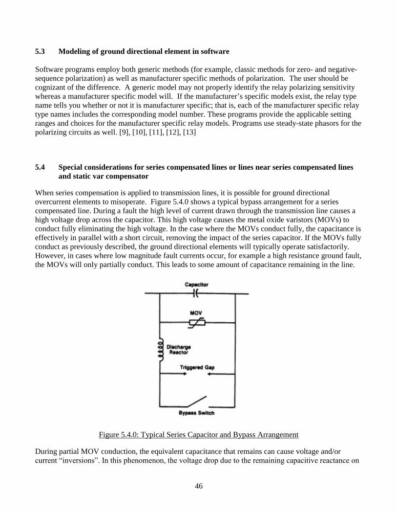
46
5.3 Modeling of ground directional element in software
Software programs employ both generic methods (for example, classic methods for zero- and negative-
sequence polarization) as well as manufacturer specific methods of polarization. The user should be
cognizant of the difference. A generic model may not properly identify the relay polarizing sensitivity
whereas a manufacturer specific model will. If the manufacturer’s specific models exist, the relay type
name tells you whether or not it is manufacturer specific; that is, each of the manufacturer specific relay
type names includes the corresponding model number. These programs provide the applicable setting
ranges and choices for the manufacturer specific relay models. Programs use steady-state phasors for the
polarizing circuits as well. [9], [10], [11], [12], [13]
5.4 Special considerations for series compensated lines or lines near series compensated lines
and static var compensator
When series compensation is applied to transmission lines, it is possible for ground directional
overcurrent elements to misoperate. Figure 5.4.0 shows a typical bypass arrangement for a series
compensated line. During a fault the high level of current drawn through the transmission line causes a
high voltage drop across the capacitor. This high voltage causes the metal oxide varistors (MOVs) to
conduct fully eliminating the high voltage. In the case where the MOVs conduct fully, the capacitance is
effectively in parallel with a short circuit, removing the impact of the series capacitor. If the MOVs fully
conduct as previously described, the ground directional elements will typically operate satisfactorily.
However, in cases where low magnitude fault currents occur, for example a high resistance ground fault,
the MOVs will only partially conduct. This leads to some amount of capacitance remaining in the line.
Figure 5.4.0: Typical Series Capacitor and Bypass Arrangement
During partial MOV conduction, the equivalent capacitance that remains can cause voltage and/or
current “inversions”. In this phenomenon, the voltage drop due to the remaining capacitive reactance on
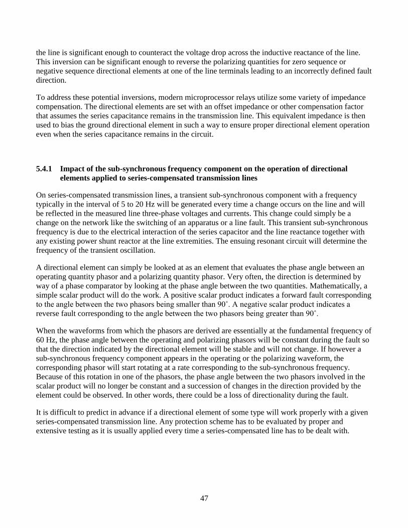
47
the line is significant enough to counteract the voltage drop across the inductive reactance of the line.
This inversion can be significant enough to reverse the polarizing quantities for zero sequence or
negative sequence directional elements at one of the line terminals leading to an incorrectly defined fault
direction.
To address these potential inversions, modern microprocessor relays utilize some variety of impedance
compensation. The directional elements are set with an offset impedance or other compensation factor
that assumes the series capacitance remains in the transmission line. This equivalent impedance is then
used to bias the ground directional element in such a way to ensure proper directional element operation
even when the series capacitance remains in the circuit.
5.4.1 Impact of the sub-synchronous frequency component on the operation of directional
elements applied to series-compensated transmission lines
On series-compensated transmission lines, a transient sub-synchronous component with a frequency
typically in the interval of 5 to 20 Hz will be generated every time a change occurs on the line and will
be reflected in the measured line three-phase voltages and currents. This change could simply be a
change on the network like the switching of an apparatus or a line fault. This transient sub-synchronous
frequency is due to the electrical interaction of the series capacitor and the line reactance together with
any existing power shunt reactor at the line extremities. The ensuing resonant circuit will determine the
frequency of the transient oscillation.
A directional element can simply be looked at as an element that evaluates the phase angle between an
operating quantity phasor and a polarizing quantity phasor. Very often, the direction is determined by
way of a phase comparator by looking at the phase angle between the two quantities. Mathematically, a
simple scalar product will do the work. A positive scalar product indicates a forward fault corresponding
to the angle between the two phasors being smaller than 90˚. A negative scalar product indicates a
reverse fault corresponding to the angle between the two phasors being greater than 90˚.
When the waveforms from which the phasors are derived are essentially at the fundamental frequency of
60 Hz, the phase angle between the operating and polarizing phasors will be constant during the fault so
that the direction indicated by the directional element will be stable and will not change. If however a
sub-synchronous frequency component appears in the operating or the polarizing waveform, the
corresponding phasor will start rotating at a rate corresponding to the sub-synchronous frequency.
Because of this rotation in one of the phasors, the phase angle between the two phasors involved in the
scalar product will no longer be constant and a succession of changes in the direction provided by the
element could be observed. In other words, there could be a loss of directionality during the fault.
It is difficult to predict in advance if a directional element of some type will work properly with a given
series-compensated transmission line. Any protection scheme has to be evaluated by proper and
extensive testing as it is usually applied every time a series-compensated line has to be dealt with.
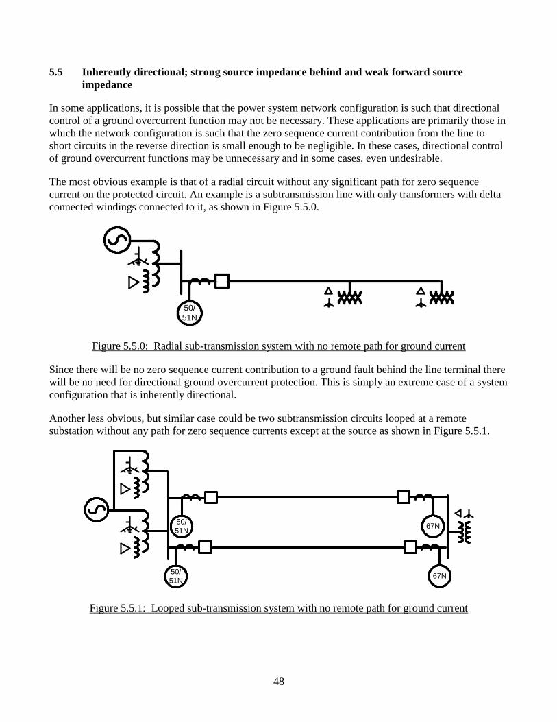
48
5.5 Inherently directional; strong source impedance behind and weak forward source
impedance
In some applications, it is possible that the power system network configuration is such that directional
control of a ground overcurrent function may not be necessary. These applications are primarily those in
which the network configuration is such that the zero sequence current contribution from the line to
short circuits in the reverse direction is small enough to be negligible. In these cases, directional control
of ground overcurrent functions may be unnecessary and in some cases, even undesirable.
The most obvious example is that of a radial circuit without any significant path for zero sequence
current on the protected circuit. An example is a subtransmission line with only transformers with delta
connected windings connected to it, as shown in Figure 5.5.0.
50/
51N
Figure 5.5.0: Radial sub-transmission system with no remote path for ground current
Since there will be no zero sequence current contribution to a ground fault behind the line terminal there
will be no need for directional ground overcurrent protection. This is simply an extreme case of a system
configuration that is inherently directional.
Another less obvious, but similar case could be two subtransmission circuits looped at a remote
substation without any path for zero sequence currents except at the source as shown in Figure 5.5.1.
50/
51N67N
50/
51N67N
Figure 5.5.1: Looped sub-transmission system with no remote path for ground current
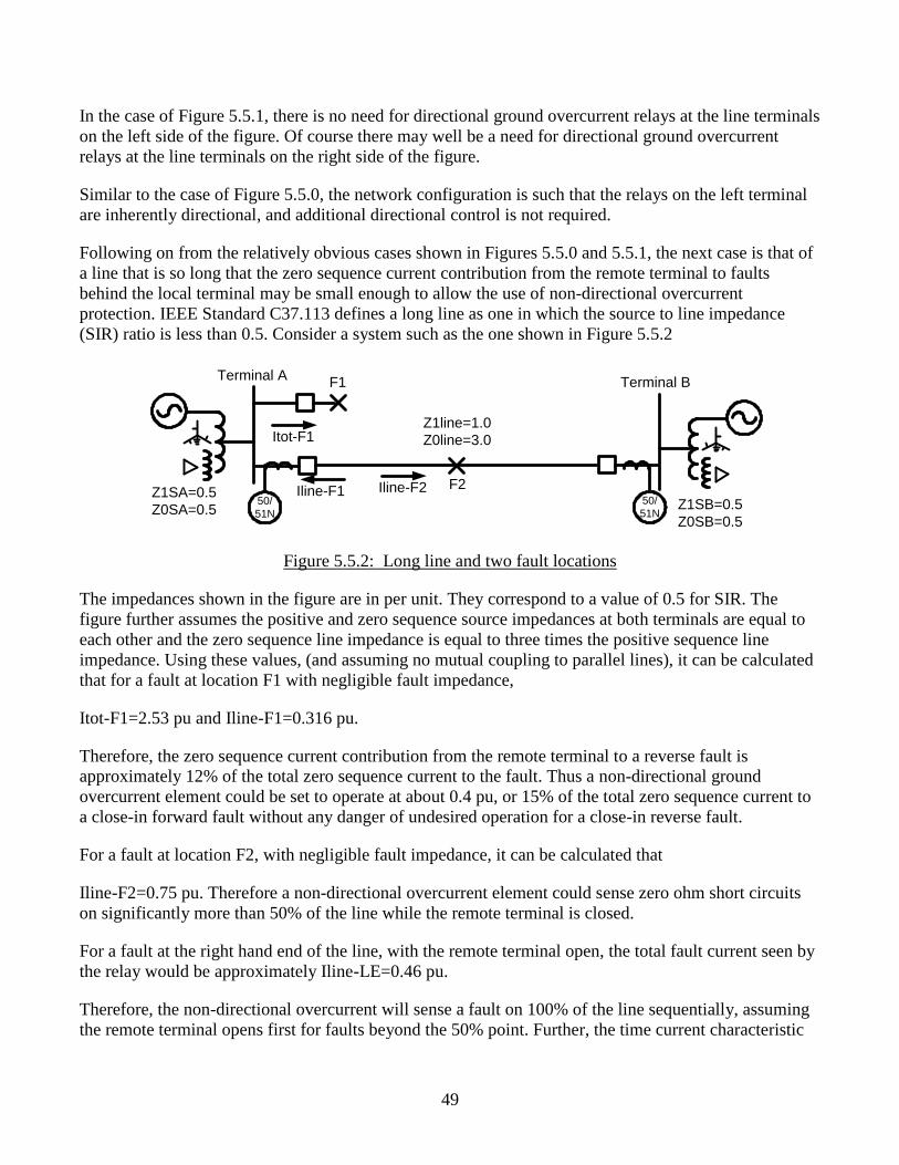
49
In the case of Figure 5.5.1, there is no need for directional ground overcurrent relays at the line terminals
on the left side of the figure. Of course there may well be a need for directional ground overcurrent
relays at the line terminals on the right side of the figure.
Similar to the case of Figure 5.5.0, the network configuration is such that the relays on the left terminal
are inherently directional, and additional directional control is not required.
Following on from the relatively obvious cases shown in Figures 5.5.0 and 5.5.1, the next case is that of
a line that is so long that the zero sequence current contribution from the remote terminal to faults
behind the local terminal may be small enough to allow the use of non-directional overcurrent
protection. IEEE Standard C37.113 defines a long line as one in which the source to line impedance
(SIR) ratio is less than 0.5. Consider a system such as the one shown in Figure 5.5.2
50/
51N
50/
51N
Terminal ATerminal B
Z1SA=0.5
Z0SA=0.5
Z1line=1.0
Z0line=3.0
Z1SB=0.5
Z0SB=0.5
F1
F2
Itot-F1
Iline-F2Iline-F1
Figure 5.5.2: Long line and two fault locations
The impedances shown in the figure are in per unit. They correspond to a value of 0.5 for SIR. The
figure further assumes the positive and zero sequence source impedances at both terminals are equal to
each other and the zero sequence line impedance is equal to three times the positive sequence line
impedance. Using these values, (and assuming no mutual coupling to parallel lines), it can be calculated
that for a fault at location F1 with negligible fault impedance,
Itot-F1=2.53 pu and Iline-F1=0.316 pu.
Therefore, the zero sequence current contribution from the remote terminal to a reverse fault is
approximately 12% of the total zero sequence current to the fault. Thus a non-directional ground
overcurrent element could be set to operate at about 0.4 pu, or 15% of the total zero sequence current to
a close-in forward fault without any danger of undesired operation for a close-in reverse fault.
For a fault at location F2, with negligible fault impedance, it can be calculated that
Iline-F2=0.75 pu. Therefore a non-directional overcurrent element could sense zero ohm short circuits
on significantly more than 50% of the line while the remote terminal is closed.
For a fault at the right hand end of the line, with the remote terminal open, the total fault current seen by
the relay would be approximately Iline-LE=0.46 pu.
Therefore, the non-directional overcurrent will sense a fault on 100% of the line sequentially, assuming
the remote terminal opens first for faults beyond the 50% point. Further, the time current characteristic
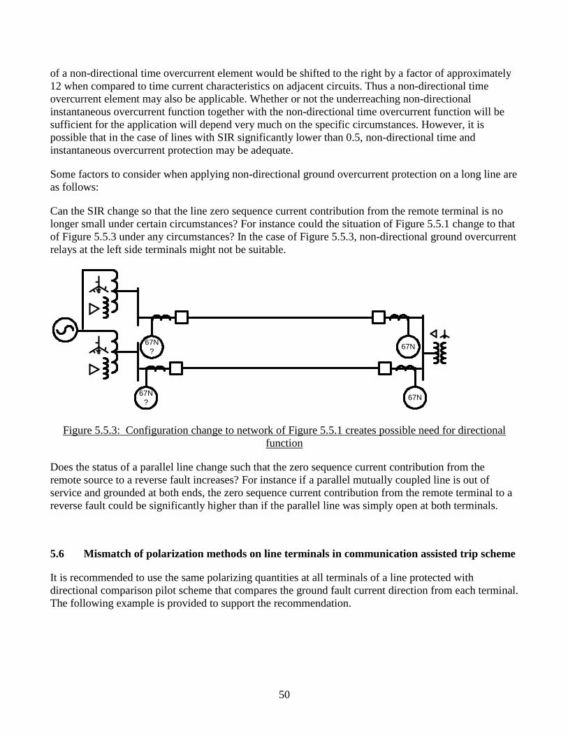
50
of a non-directional time overcurrent element would be shifted to the right by a factor of approximately
12 when compared to time current characteristics on adjacent circuits. Thus a non-directional time
overcurrent element may also be applicable. Whether or not the underreaching non-directional
instantaneous overcurrent function together with the non-directional time overcurrent function will be
sufficient for the application will depend very much on the specific circumstances. However, it is
possible that in the case of lines with SIR significantly lower than 0.5, non-directional time and
instantaneous overcurrent protection may be adequate.
Some factors to consider when applying non-directional ground overcurrent protection on a long line are
as follows:
Can the SIR change so that the line zero sequence current contribution from the remote terminal is no
longer small under certain circumstances? For instance could the situation of Figure 5.5.1 change to that
of Figure 5.5.3 under any circumstances? In the case of Figure 5.5.3, non-directional ground overcurrent
relays at the left side terminals might not be suitable.
67N
?67N
67N
?67N
Figure 5.5.3: Configuration change to network of Figure 5.5.1 creates possible need for directional
function
Does the status of a parallel line change such that the zero sequence current contribution from the
remote source to a reverse fault increases? For instance if a parallel mutually coupled line is out of
service and grounded at both ends, the zero sequence current contribution from the remote terminal to a
reverse fault could be significantly higher than if the parallel line was simply open at both terminals.
5.6 Mismatch of polarization methods on line terminals in communication assisted trip scheme
It is recommended to use the same polarizing quantities at all terminals of a line protected with
directional comparison pilot scheme that compares the ground fault current direction from each terminal.
The following example is provided to support the recommendation.
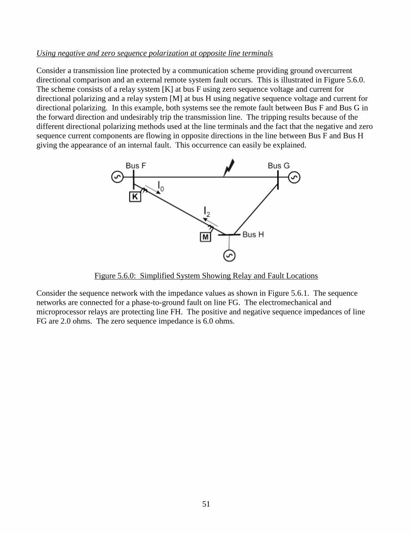
51
Using negative and zero sequence polarization at opposite line terminals
Consider a transmission line protected by a communication scheme providing ground overcurrent
directional comparison and an external remote system fault occurs. This is illustrated in Figure 5.6.0.
The scheme consists of a relay system [K] at bus F using zero sequence voltage and current for
directional polarizing and a relay system [M] at bus H using negative sequence voltage and current for
directional polarizing. In this example, both systems see the remote fault between Bus F and Bus G in
the forward direction and undesirably trip the transmission line. The tripping results because of the
different directional polarizing methods used at the line terminals and the fact that the negative and zero
sequence current components are flowing in opposite directions in the line between Bus F and Bus H
giving the appearance of an internal fault. This occurrence can easily be explained.
Figure 5.6.0: Simplified System Showing Relay and Fault Locations
Consider the sequence network with the impedance values as shown in Figure 5.6.1. The sequence
networks are connected for a phase-to-ground fault on line FG. The electromechanical and
microprocessor relays are protecting line FH. The positive and negative sequence impedances of line
FG are 2.0 ohms. The zero sequence impedance is 6.0 ohms.
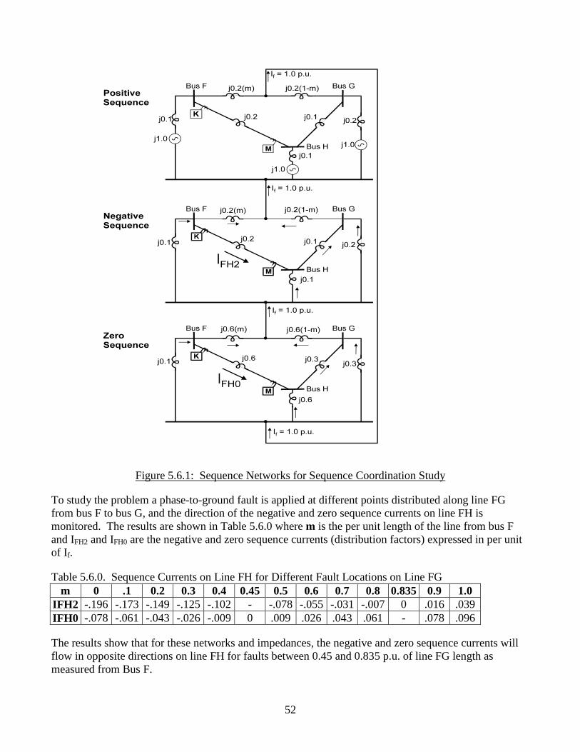
52
Figure 5.6.1: Sequence Networks for Sequence Coordination Study
To study the problem a phase-to-ground fault is applied at different points distributed along line FG
from bus F to bus G, and the direction of the negative and zero sequence currents on line FH is
monitored. The results are shown in Table 5.6.0 where m is the per unit length of the line from bus F
and IFH2 and IFH0 are the negative and zero sequence currents (distribution factors) expressed in per unit
of If.
Table 5.6.0. Sequence Currents on Line FH for Different Fault Locations on Line FG
m 0 .1 0.2 0.3 0.4 0.45 0.5 0.6 0.7 0.8 0.835 0.9 1.0
IFH2 -.196 -.173 -.149 -.125 -.102 - -.078 -.055 -.031 -.007 0 .016 .039
IFH0 -.078 -.061 -.043 -.026 -.009 0 .009 .026 .043 .061 - .078 .096
The results show that for these networks and impedances, the negative and zero sequence currents will
flow in opposite directions on line FH for faults between 0.45 and 0.835 p.u. of line FG length as
measured from Bus F.
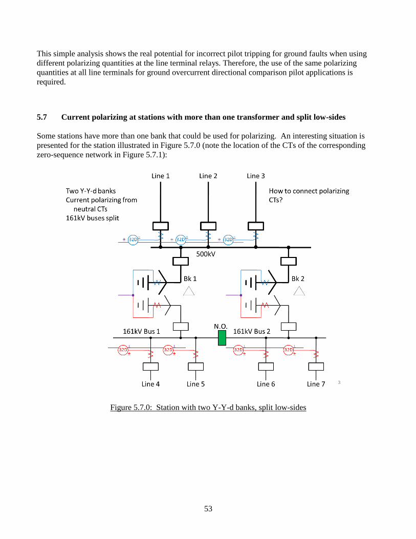
53
This simple analysis shows the real potential for incorrect pilot tripping for ground faults when using
different polarizing quantities at the line terminal relays. Therefore, the use of the same polarizing
quantities at all line terminals for ground overcurrent directional comparison pilot applications is
required.
5.7 Current polarizing at stations with more than one transformer and split low-sides
Some stations have more than one bank that could be used for polarizing. An interesting situation is
presented for the station illustrated in Figure 5.7.0 (note the location of the CTs of the corresponding
zero-sequence network in Figure 5.7.1):
Figure 5.7.0: Station with two Y-Y-d banks, split low-sides
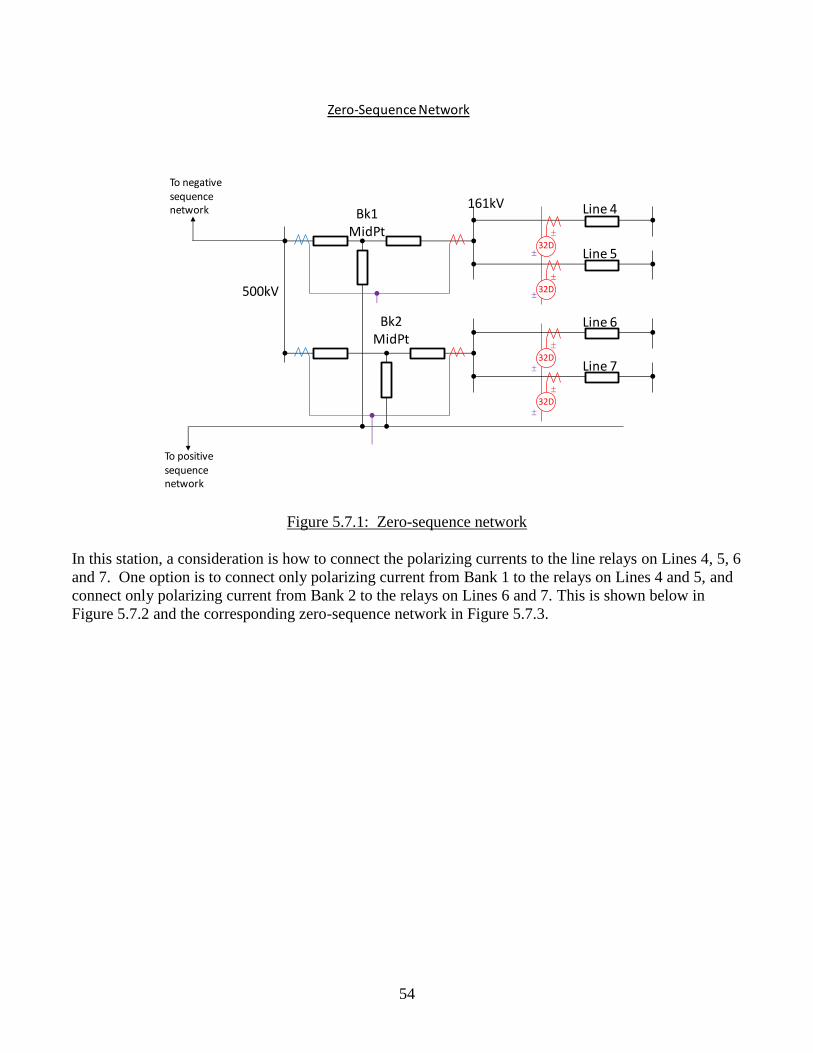
54
Figure 5.7.1: Zero-sequence network
In this station, a consideration is how to connect the polarizing currents to the line relays on Lines 4, 5, 6
and 7. One option is to connect only polarizing current from Bank 1 to the relays on Lines 4 and 5, and
connect only polarizing current from Bank 2 to the relays on Lines 6 and 7. This is shown below in
Figure 5.7.2 and the corresponding zero-sequence network in Figure 5.7.3.
To negative sequence network
To positive sequence network
500kV
Bk1 MidPt
161kV
Bk2 MidPt
Line 4
Line 5
Line 6
Line 7
32D
32D
32D
32D
Zero-Sequence Network
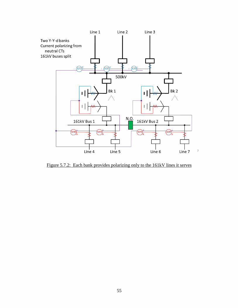
55
Figure 5.7.2: Each bank provides polarizing only to the 161kV lines it serves
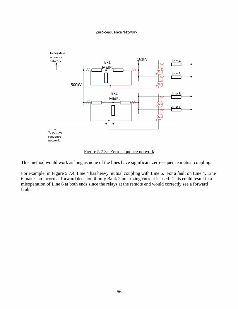
56
Figure 5.7.3: Zero-sequence network
This method would work as long as none of the lines have significant zero-sequence mutual coupling.
For example, in Figure 5.7.4, Line 4 has heavy mutual coupling with Line 6. For a fault on Line 4, Line
6 makes an incorrect forward decision if only Bank 2 polarizing current is used. This could result in a
misoperation of Line 6 at both ends since the relays at the remote end would correctly see a forward
fault.
To negative sequence network
To positive sequence network
500kV
Bk1 MidPt
161kV
Bk2 MidPt
Line 4
Line 5
Line 6
Line 7
32D
32D
32D
32D
Zero-Sequence Network
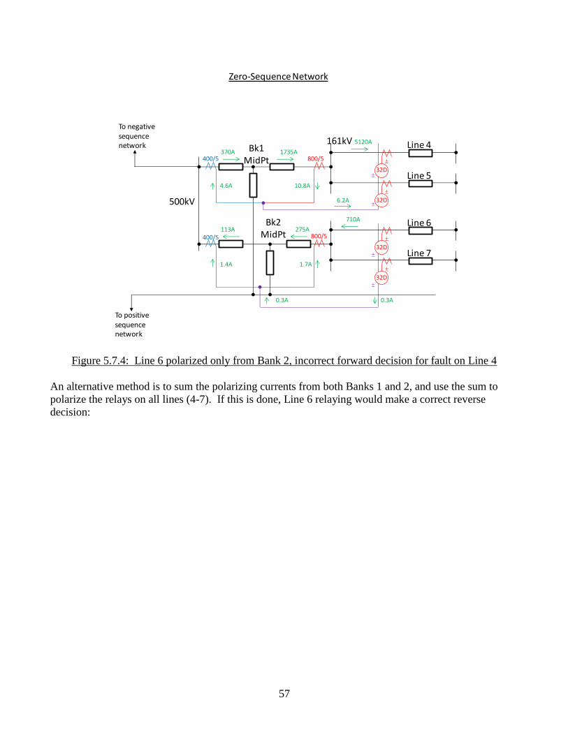
57
Figure 5.7.4: Line 6 polarized only from Bank 2, incorrect forward decision for fault on Line 4
An alternative method is to sum the polarizing currents from both Banks 1 and 2, and use the sum to
polarize the relays on all lines (4-7). If this is done, Line 6 relaying would make a correct reverse
decision:
To negative sequence network
To positive sequence network
500kV
Bk1 MidPt
161kV
Bk2 MidPt
Line 4
Line 5
Line 6
Line 7
32D
32D
32D
32D
Zero-Sequence Network
1735A370A
275A113A
710A
5120A
6.2A
0.3A 0.3A
400/5
400/5
800/5
800/5
10.8A4.6A
1.4A 1.7A
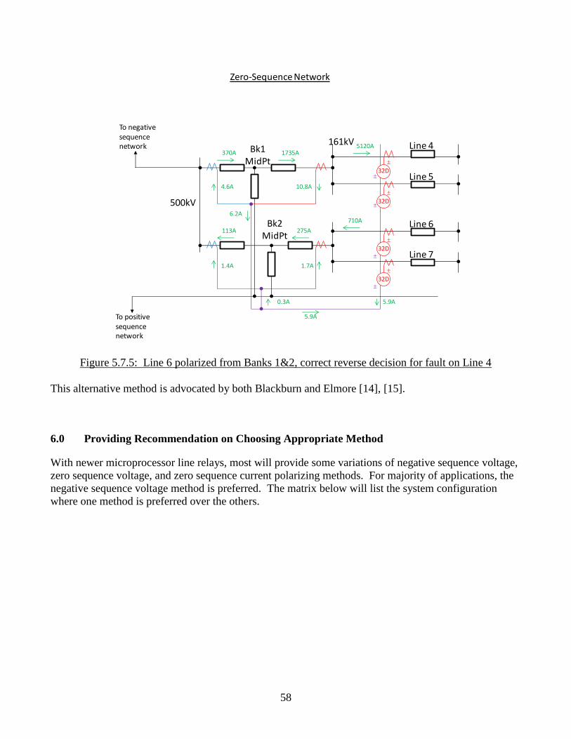
58
Figure 5.7.5: Line 6 polarized from Banks 1&2, correct reverse decision for fault on Line 4
This alternative method is advocated by both Blackburn and Elmore [14], [15].
6.0 Providing Recommendation on Choosing Appropriate Method
With newer microprocessor line relays, most will provide some variations of negative sequence voltage,
zero sequence voltage, and zero sequence current polarizing methods. For majority of applications, the
negative sequence voltage method is preferred. The matrix below will list the system configuration
where one method is preferred over the others.
To negative sequence network
To positive sequence network
500kV
Bk1 MidPt
161kV
Bk2 MidPt
Line 4
Line 5
Line 6
Line 7
32D
32D
32D
32D
Zero-Sequence Network
1735A370A
275A113A
710A
5120A
6.2A
0.3A
5.9A
10.8A4.6A
1.4A 1.7A
5.9A
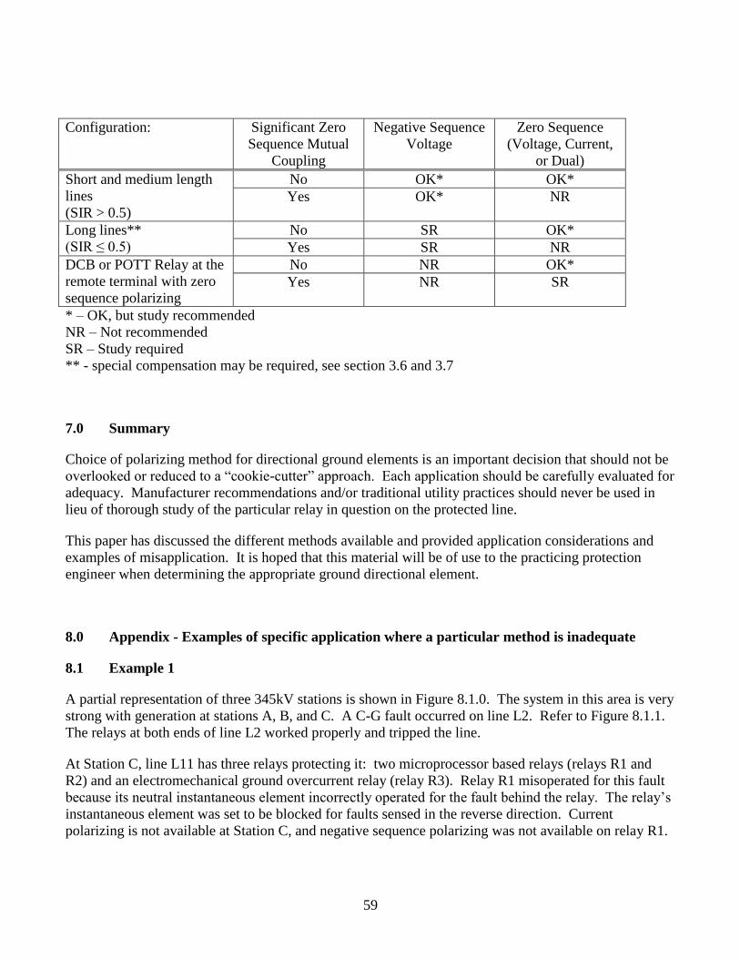
59
Configuration: Significant Zero
Sequence Mutual
Coupling
Negative Sequence
Voltage
Zero Sequence
(Voltage, Current,
or Dual)
Short and medium length
lines
(SIR > 0.5)
No OK* OK*
Yes OK* NR
Long lines**
(SIR ≤ 0.5)
No SR OK*
Yes SR NR
DCB or POTT Relay at the
remote terminal with zero
sequence polarizing
No NR OK*
Yes NR SR
* – OK, but study recommended
NR – Not recommended
SR – Study required
** - special compensation may be required, see section 3.6 and 3.7
7.0 Summary
Choice of polarizing method for directional ground elements is an important decision that should not be
overlooked or reduced to a “cookie-cutter” approach. Each application should be carefully evaluated for
adequacy. Manufacturer recommendations and/or traditional utility practices should never be used in
lieu of thorough study of the particular relay in question on the protected line.
This paper has discussed the different methods available and provided application considerations and
examples of misapplication. It is hoped that this material will be of use to the practicing protection
engineer when determining the appropriate ground directional element.
8.0 Appendix - Examples of specific application where a particular method is inadequate
8.1 Example 1
A partial representation of three 345kV stations is shown in Figure 8.1.0. The system in this area is very
strong with generation at stations A, B, and C. A C-G fault occurred on line L2. Refer to Figure 8.1.1.
The relays at both ends of line L2 worked properly and tripped the line.
At Station C, line L11 has three relays protecting it: two microprocessor based relays (relays R1 and
R2) and an electromechanical ground overcurrent relay (relay R3). Relay R1 misoperated for this fault
because its neutral instantaneous element incorrectly operated for the fault behind the relay. The relay’s
instantaneous element was set to be blocked for faults sensed in the reverse direction. Current
polarizing is not available at Station C, and negative sequence polarizing was not available on relay R1.
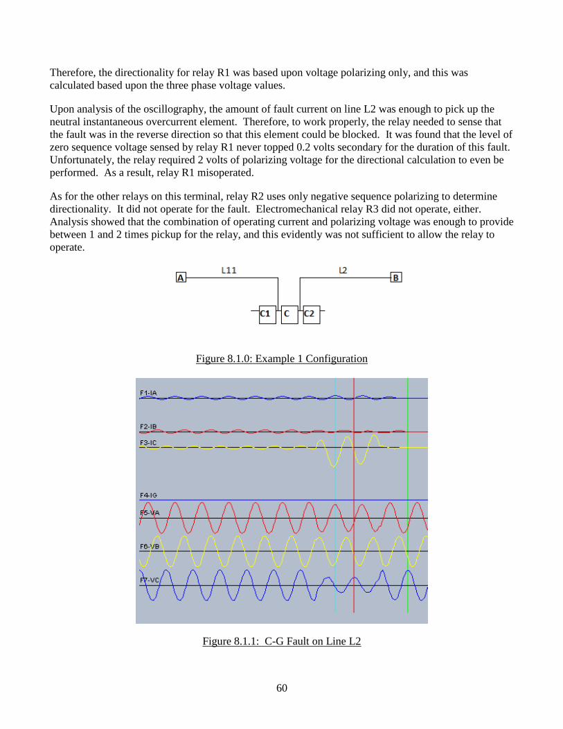
60
Therefore, the directionality for relay R1 was based upon voltage polarizing only, and this was
calculated based upon the three phase voltage values.
Upon analysis of the oscillography, the amount of fault current on line L2 was enough to pick up the
neutral instantaneous overcurrent element. Therefore, to work properly, the relay needed to sense that
the fault was in the reverse direction so that this element could be blocked. It was found that the level of
zero sequence voltage sensed by relay R1 never topped 0.2 volts secondary for the duration of this fault.
Unfortunately, the relay required 2 volts of polarizing voltage for the directional calculation to even be
performed. As a result, relay R1 misoperated.
As for the other relays on this terminal, relay R2 uses only negative sequence polarizing to determine
directionality. It did not operate for the fault. Electromechanical relay R3 did not operate, either.
Analysis showed that the combination of operating current and polarizing voltage was enough to provide
between 1 and 2 times pickup for the relay, and this evidently was not sufficient to allow the relay to
operate.
Figure 8.1.0: Example 1 Configuration
Figure 8.1.1: C-G Fault on Line L2
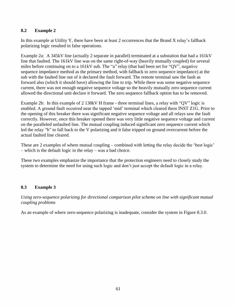
61
8.2 Example 2
In this example at Utility Y, there have been at least 2 occurrences that the Brand X relay’s fallback
polarizing logic resulted in false operations.
Example 2a: A 345kV line (actually 2 separate in parallel) terminated at a substation that had a 161kV
line that faulted. The 161kV line was on the same right-of-way (heavily mutually coupled) for several
miles before continuing on to a 161kV sub. The “a” relay (that had been set for “QV”, negative
sequence impedance method as the primary method, with fallback to zero sequence impedance) at the
sub with the faulted line out of it declared the fault forward. The remote terminal saw the fault as
forward also (which it should have) allowing the line to trip. While there was some negative sequence
current, there was not enough negative sequence voltage so the heavily mutually zero sequence current
allowed the directional unit declare it forward. The zero sequence fallback option has to be removed.
Example 2b: In this example of 2 138kV H frame - three terminal lines, a relay with “QV” logic is
enabled. A ground fault occurred near the tapped ‘mid’ terminal which cleared there INST Z1G. Prior to
the opening of this breaker there was significant negative sequence voltage and all relays saw the fault
correctly. However, once this breaker opened there was very little negative sequence voltage and current
on the paralleled unfaulted line. The mutual coupling induced significant zero sequence current which
led the relay “b” to fall back to the V polarizing and it false tripped on ground overcurrent before the
actual faulted line cleared.
These are 2 examples of where mutual coupling – combined with letting the relay decide the ‘best logic’
– which is the default logic in the relay – was a bad choice.
These two examples emphasize the importance that the protection engineers need to closely study the
system to determine the need for using such logic and don’t just accept the default logic in a relay.
8.3 Example 3
Using zero-sequence polarizing for directional comparison pilot scheme on line with significant mutual
coupling problems
As an example of where zero-sequence polarizing is inadequate, consider the system in Figure 8.3.0.
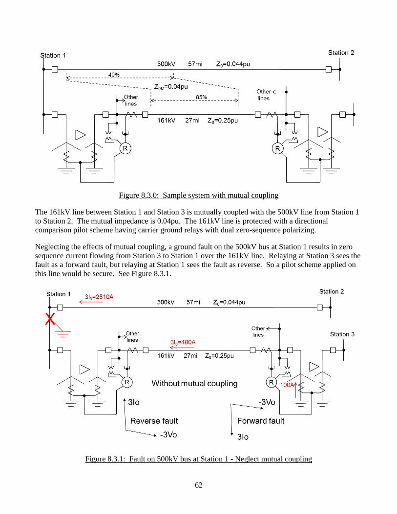
62
Figure 8.3.0: Sample system with mutual coupling
The 161kV line between Station 1 and Station 3 is mutually coupled with the 500kV line from Station 1
to Station 2. The mutual impedance is 0.04pu. The 161kV line is protected with a directional
comparison pilot scheme having carrier ground relays with dual zero-sequence polarizing.
Neglecting the effects of mutual coupling, a ground fault on the 500kV bus at Station 1 results in zero
sequence current flowing from Station 3 to Station 1 over the 161kV line. Relaying at Station 3 sees the
fault as a forward fault, but relaying at Station 1 sees the fault as reverse. So a pilot scheme applied on
this line would be secure. See Figure 8.3.1.
Figure 8.3.1: Fault on 500kV bus at Station 1 - Neglect mutual coupling
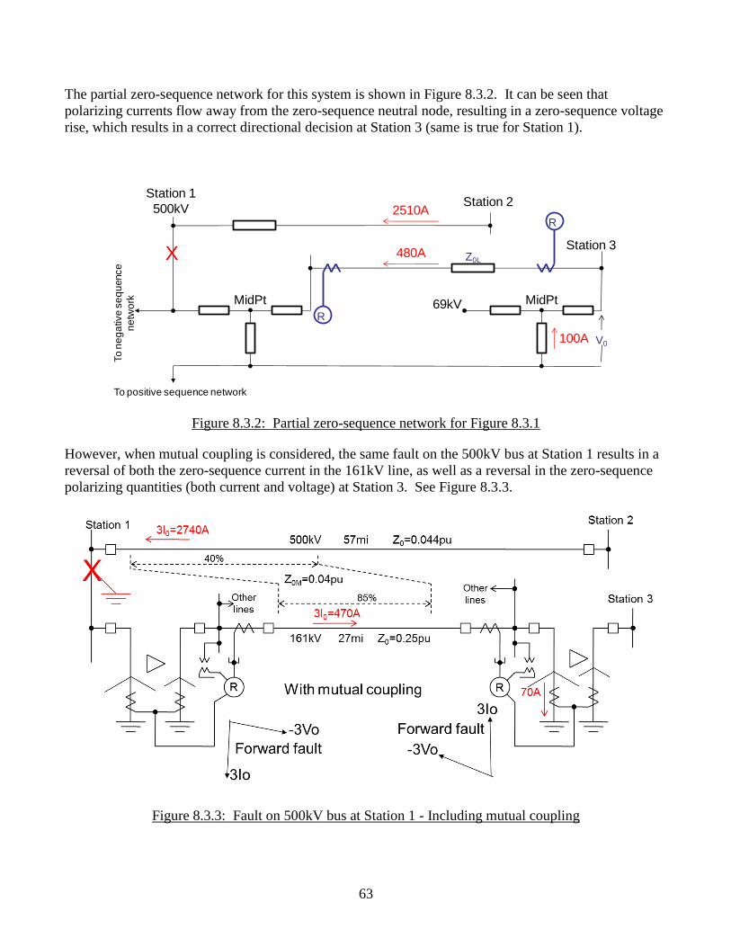
63
The partial zero-sequence network for this system is shown in Figure 8.3.2. It can be seen that
polarizing currents flow away from the zero-sequence neutral node, resulting in a zero-sequence voltage
rise, which results in a correct directional decision at Station 3 (same is true for Station 1).
Figure 8.3.2: Partial zero-sequence network for Figure 8.3.1
However, when mutual coupling is considered, the same fault on the 500kV bus at Station 1 results in a
reversal of both the zero-sequence current in the 161kV line, as well as a reversal in the zero-sequence
polarizing quantities (both current and voltage) at Station 3. See Figure 8.3.3.
Figure 8.3.3: Fault on 500kV bus at Station 1 - Including mutual coupling
Station 3
69kV
Station 1
500kV
MidPt MidPt
To positive sequence network
To
ne
ga
tive
se
qu
ence
ne
two
rk
Station 2
R
R
V0
Z0LX
2510A
480A
100A
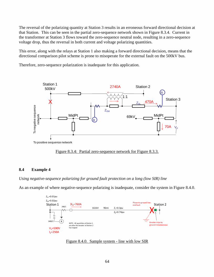
64
The reversal of the polarizing quantity at Station 3 results in an erroneous forward directional decision at
that Station. This can be seen in the partial zero-sequence network shown in Figure 8.3.4. Current in
the transformer at Station 3 flows toward the zero-sequence neutral node, resulting in a zero-sequence
voltage drop, thus the reversal in both current and voltage polarizing quantities.
This error, along with the relays at Station 1 also making a forward directional decision, means that the
directional comparison pilot scheme is prone to misoperate for the external fault on the 500kV bus.
Therefore, zero-sequence polarization is inadequate for this application.
Figure 8.3.4: Partial zero-sequence network for Figure 8.3.3.
8.4 Example 4
Using negative-sequence polarizing for ground fault protection on a long (low SIR) line
As an example of where negative-sequence polarizing is inadequate, consider the system in Figure 8.4.0.
Figure 8.4.0. Sample system - line with low SIR
Station 3
69kV
Station 1
500kV
MidPt MidPt
To positive sequence network
To
ne
ga
tive
se
qu
ence
ne
two
rk
Station 2
R
R
V0
Z0LX
Z0M
1:1
2740A
470A
70A
161kV
Station 1 Station 2
R
96mi Z+=0.3pu
Z0=0.74pu
ZS+=0.01pu
ZS0=0.02pu
XPhase-to-ground line-end fault3I0=760A
V2=590VI2=250A
240/1
1400/1Breaker trips by ground instantaneous
NOTE: All quantities at Station 1 are after the breaker at Station 2 has tripped
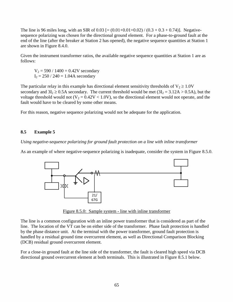
65
The line is 96 miles long, with an SIR of 0.03 [= (0.01+0.01+0.02) / (0.3 + 0.3 + 0.74)]. Negative-
sequence polarizing was chosen for the directional ground element. For a phase-to-ground fault at the
end of the line (after the breaker at Station 2 has opened), the negative sequence quantities at Station 1
are shown in Figure 8.4.0.
Given the instrument transformer ratios, the available negative sequence quantities at Station 1 are as
follows:
V2 = 590 / 1400 = 0.42V secondary
I2 = 250 / 240 = 1.04A secondary
The particular relay in this example has directional element sensitivity thresholds of V2 1.0V
secondary and 3I2 0.5A secondary. The current threshold would be met (3I2 = 3.12A > 0.5A), but the
voltage threshold would not (V2 = 0.42V < 1.0V), so the directional element would not operate, and the
fault would have to be cleared by some other means.
For this reason, negative sequence polarizing would not be adequate for the application.
8.5 Example 5
Using negative-sequence polarizing for ground fault protection on a line with inline transformer
As an example of where negative-sequence polarizing is inadequate, consider the system in Figure 8.5.0.
Figure 8.5.0: Sample system - line with inline transformer
The line is a common configuration with an inline power transformer that is considered as part of the
line. The location of the VT can be on either side of the transformer. Phase fault protection is handled
by the phase distance unit. At the terminal with the power transformer, ground fault protection is
handled by a residual ground time overcurrent element, as well as Directional Comparison Blocking
(DCB) residual ground overcurrent element.
For a close-in ground fault at the line side of the transformer, the fault is cleared high speed via DCB
directional ground overcurrent element at both terminals. This is illustrated in Figure 8.5.1 below.
21/67G
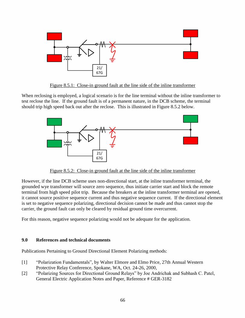
66
Figure 8.5.1: Close-in ground fault at the line side of the inline transformer
When reclosing is employed, a logical scenario is for the line terminal without the inline transformer to
test reclose the line. If the ground fault is of a permanent nature, in the DCB scheme, the terminal
should trip high speed back out after the reclose. This is illustrated in Figure 8.5.2 below.
Figure 8.5.2: Close-in ground fault at the line side of the inline transformer
However, if the line DCB scheme uses non-directional start, at the inline transformer terminal, the
grounded wye transformer will source zero sequence, thus initiate carrier start and block the remote
terminal from high speed pilot trip. Because the breakers at the inline transformer terminal are opened,
it cannot source positive sequence current and thus negative sequence current. If the directional element
is set to negative sequence polarizing, directional decision cannot be made and thus cannot stop the
carrier, the ground fault can only be cleared by residual ground time overcurrent.
For this reason, negative sequence polarizing would not be adequate for the application.
9.0 References and technical documents
Publications Pertaining to Ground Directional Element Polarizing methods:
[1] “Polarization Fundamentals”, by Walter Elmore and Elmo Price, 27th Annual Western
Protective Relay Conference, Spokane, WA, Oct. 24-26, 2000,
[2] “Polarizing Sources for Directional Ground Relays” by Joe Andrichak and Subhash C. Patel,
General Electric Application Notes and Paper, Reference # GER-3182
21/67G
21/67G
67
[3] “Comparing Ground Directional Element Performance Using Field Data” by Karl Zimmerman
and Joe Mooney, Schweitzer Engineering Laboratories, Inc., Technical paper date code
19930401
[4] “Ground Fault Relay Protection of Transmission Lines” by J.L. Blackburn, AIEE Transaction
Part III, Vol 71, pg 685-691, Aug 1952
[5] “Ground Relay Polarization” by J.L. Blackburn, AIEE Transaction Part III, Vol 71, pg 1088-
1093, Dec 1952
[6] “The Art and Science of Protective Relaying”, Chapter 13 Line Protection with Overcurrent
Relays, Section: Polarizing the Directional Units of Ground Relays, Section: Negative-phase-
sequence directional Units for Ground-fault Relaying, by C. Russell Mason,
[7] “Effect of Load Flow on Relay Performance”, General Electric Application Notes and Paper,
Reference # GER-3743
[8] “Advanced Application Guidelines for Ground Fault Protection”, by Joe Mooney, 28th Annual
Western Protective Relay Conference, Spokane, WA, Oct. 23-25, 2001
[9] "Arrows in One-Line Displays in the Computer-Aided Protection Engineering System (CAPE),"
Prepared for CAPE Users' Group, Electrocon International, Inc., Ann Arbor MI; June 20-21,
2006
[10] "Setting SEL-321 Relays," Electrocon International, Inc., Ann Arbor MI; November 11, 2008
[11] "Generic Distance Relay UTP-100#WPSC1," Electrocon International, Inc., Ann Arbor MI;
August 24, 1998
[12] "Automatic Relay Setting", by Donald M. MacGregor, A. T. ("Tony") Giuliante, and Russell W.
Patterson, presented at 56th Annual Georgia Tech Protective Relaying Conference, Atlanta,
Georgia; May 1-3, 2002, and at 55th Annual Conference for Protective Relay Engineers, Texas
A&M University, College Station, Texas; April 9-11, 2002
[13] "Line Differential Relays," Electrocon International, Inc., Ann Arbor MI; June 24-25, 2008
[14] “Protective Relaying – Principles and Applications”, 3rd
edition, J.L. Blackburn, Chapter 12,
Section 12.24, pp 460-461
[15] “ABB Protective Relaying Theory and Applications”, 2nd
edition, Revised and Expanded, W. A.
Elmore, Chapter 12, Section 3. 4, pp 243-244
[16] "CCVT Failure due to Improper Design of Auxiliary Voltage Transformers", Davarpanah M, et
all, IEEE Transactions on Power Delivery, Jan. 2012, pp. 391-400
Recommended