Unit – II/Computer Networking Truba College of Science & Tenhnology, Bhopal
Prepared By:- Ms. Nandini Sharma(CSE Deptt.) Page 1
Introduction
Data Link Layer transform the physical layer, a raw transmission facility, to a link
responsible for node-to-node communication. Specific responsibility of DLL include
framing, addressing, flow control, error control and media access control.
Data Link Layer Design Issues The DLL has a number of specific functions it can carry
out. These functions include:
1. Providing a well-defined service interface to the network layer.
2. Dealing with transmission errors.
3. Regulating the flow of data so that slow receivers are not swamped by fast senders.
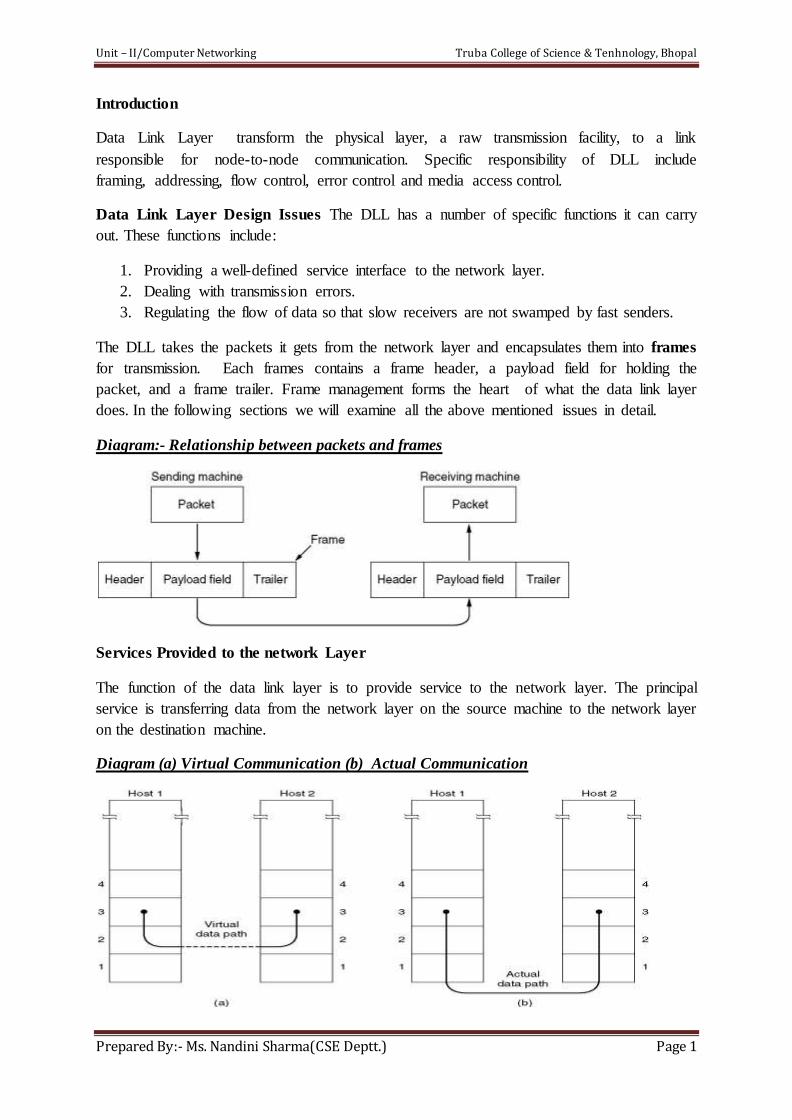
The DLL takes the packets it gets from the network layer and encapsulates them into frames
for transmission. Each frames contains a frame header, a payload field for holding the
packet, and a frame trailer. Frame management forms the heart of what the data link layer
does. In the following sections we will examine all the above mentioned issues in detail.
Diagram:- Relationship between packets and frames
Services Provided to the network Layer
The function of the data link layer is to provide service to the network layer. The principal
service is transferring data from the network layer on the source machine to the network layer
on the destination machine.
Diagram (a) Virtual Communication (b) Actual Communication
Unit – II/Computer Networking Truba College of Science & Tenhnology, Bhopal
Prepared By:- Ms. Nandini Sharma(CSE Deptt.) Page 2
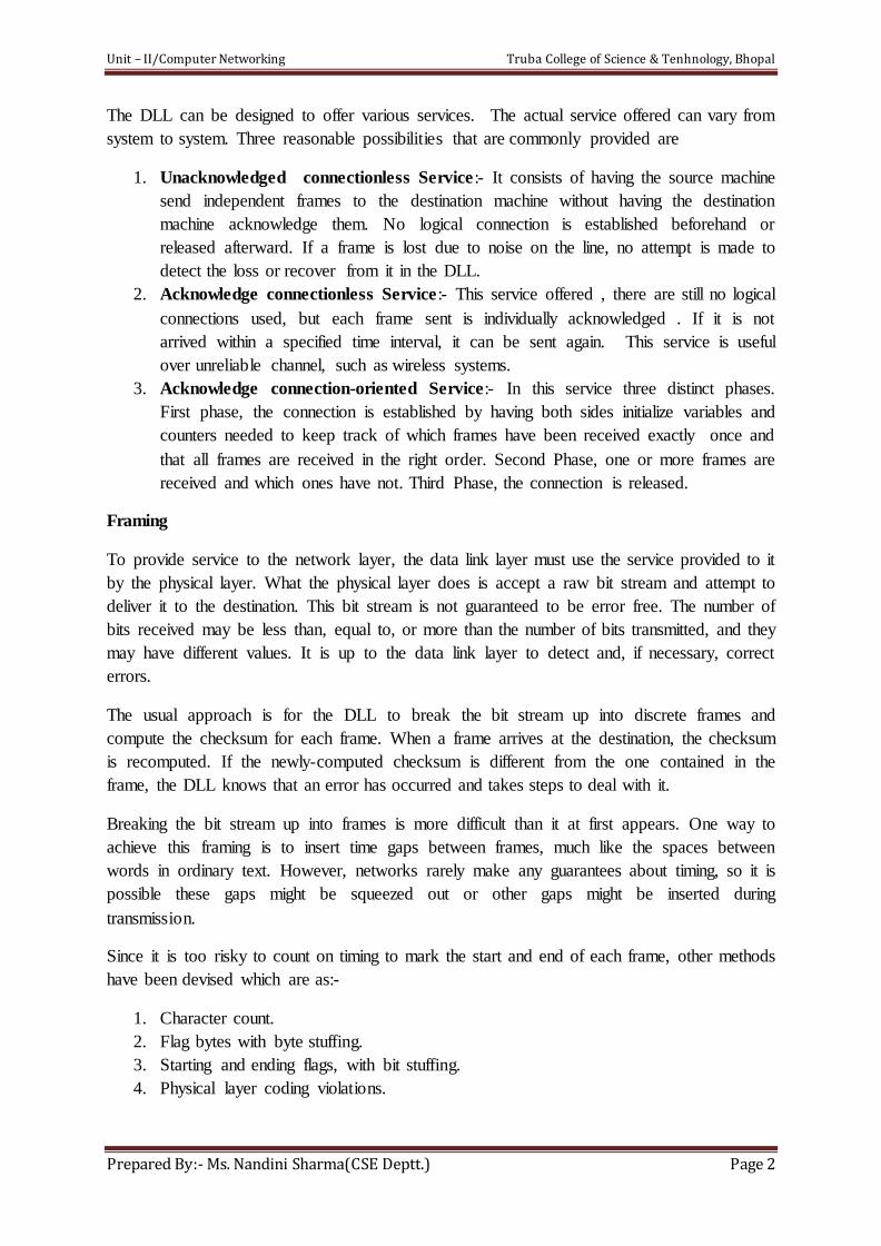
The DLL can be designed to offer various services. The actual service offered can vary from
system to system. Three reasonable possibilities that are commonly provided are
1. Unacknowledged connectionless Service:- It consists of having the source machine
send independent frames to the destination machine without having the destination
machine acknowledge them. No logical connection is established beforehand or
released afterward. If a frame is lost due to noise on the line, no attempt is made to
detect the loss or recover from it in the DLL.
2. Acknowledge connectionless Service:- This service offered , there are still no logical
connections used, but each frame sent is individually acknowledged . If it is not
arrived within a specified time interval, it can be sent again. This service is useful
over unreliable channel, such as wireless systems.
3. Acknowledge connection-oriented Service:- In this service three distinct phases.
First phase, the connection is established by having both sides initialize variables and
counters needed to keep track of which frames have been received exactly once and
that all frames are received in the right order. Second Phase, one or more frames are
received and which ones have not. Third Phase, the connection is released.
Framing
To provide service to the network layer, the data link layer must use the service provided to it
by the physical layer. What the physical layer does is accept a raw bit stream and attempt to
deliver it to the destination. This bit stream is not guaranteed to be error free. The number of
bits received may be less than, equal to, or more than the number of bits transmitted, and they
may have different values. It is up to the data link layer to detect and, if necessary, correct
errors.
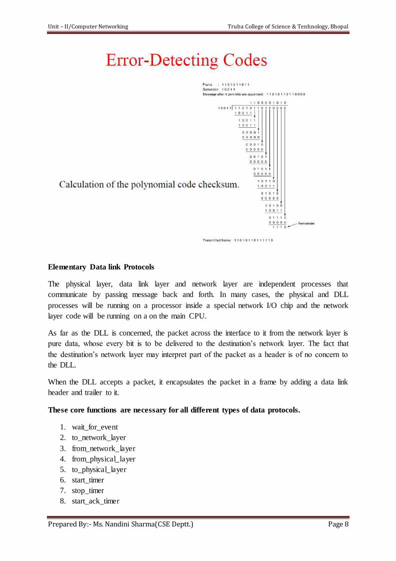
The usual approach is for the DLL to break the bit stream up into discrete frames and
compute the checksum for each frame. When a frame arrives at the destination, the checksum
is recomputed. If the newly-computed checksum is different from the one contained in the
frame, the DLL knows that an error has occurred and takes steps to deal with it.
Breaking the bit stream up into frames is more difficult than it at first appears. One way to
achieve this framing is to insert time gaps between frames, much like the spaces between
words in ordinary text. However, networks rarely make any guarantees about timing, so it is
possible these gaps might be squeezed out or other gaps might be inserted during
transmission.
Since it is too risky to count on timing to mark the start and end of each frame, other methods
have been devised which are as:-
1. Character count.
2. Flag bytes with byte stuffing.
3. Starting and ending flags, with bit stuffing.
4. Physical layer coding violations.
Unit – II/Computer Networking Truba College of Science & Tenhnology, Bhopal
Prepared By:- Ms. Nandini Sharma(CSE Deptt.) Page 3
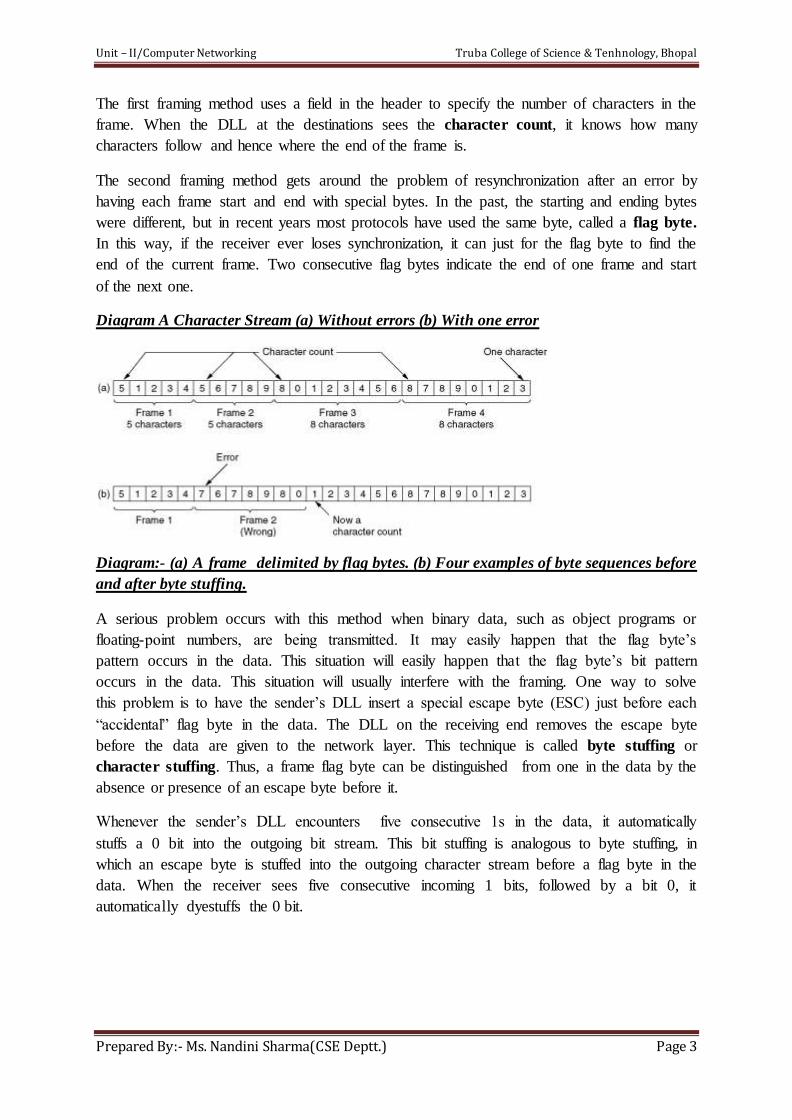
The first framing method uses a field in the header to specify the number of characters in the
frame. When the DLL at the destinations sees the character count, it knows how many
characters follow and hence where the end of the frame is.
The second framing method gets around the problem of resynchronization after an error by
having each frame start and end with special bytes. In the past, the starting and ending bytes
were different, but in recent years most protocols have used the same byte, called a flag byte.
In this way, if the receiver ever loses synchronization, it can just for the flag byte to find the
end of the current frame. Two consecutive flag bytes indicate the end of one frame and start
of the next one.
Diagram A Character Stream (a) Without errors (b) With one error
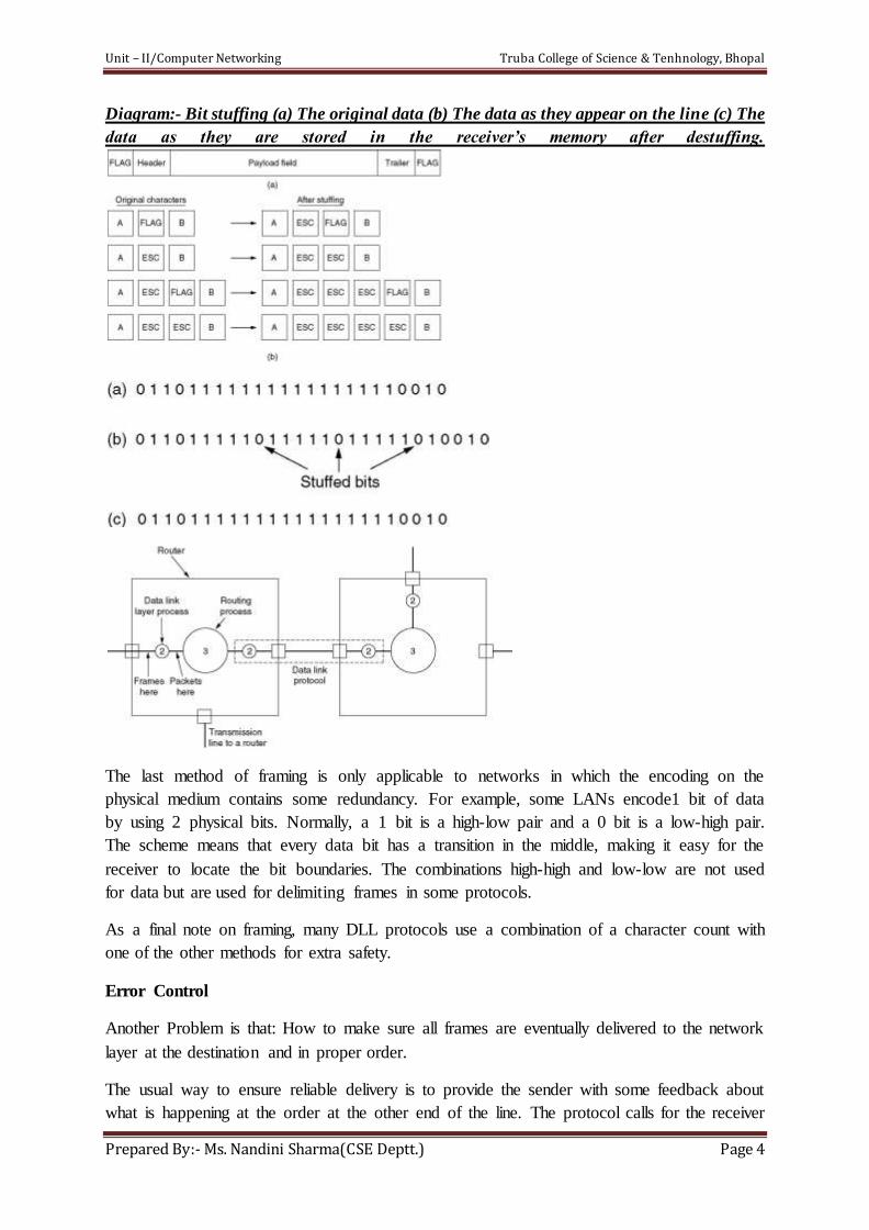
Diagram:- (a) A frame delimited by flag bytes. (b) Four examples of byte sequences before
and after byte stuffing.
A serious problem occurs with this method when binary data, such as object programs or
floating-point numbers, are being transmitted. It may easily happen that the flag byte’s
pattern occurs in the data. This situation will easily happen that the flag byte’s bit pattern
occurs in the data. This situation will usually interfere with the framing. One way to solve
this problem is to have the sender’s DLL insert a special escape byte (ESC) just before each
“accidental” flag byte in the data. The DLL on the receiving end removes the escape byte
before the data are given to the network layer. This technique is called byte stuffing or
character stuffing. Thus, a frame flag byte can be distinguished from one in the data by the
absence or presence of an escape byte before it.
Whenever the sender’s DLL encounters five consecutive 1s in the data, it automatically
stuffs a 0 bit into the outgoing bit stream. This bit stuffing is analogous to byte stuffing, in
which an escape byte is stuffed into the outgoing character stream before a flag byte in the
data. When the receiver sees five consecutive incoming 1 bits, followed by a bit 0, it
automatically dyestuffs the 0 bit.
Unit – II/Computer Networking Truba College of Science & Tenhnology, Bhopal
Prepared By:- Ms. Nandini Sharma(CSE Deptt.) Page 4
Diagram:- Bit stuffing (a) The original data (b) The data as they appear on the line (c) The
data as they are stored in the receiver’s memory after destuffing.
The last method of framing is only applicable to networks in which the encoding on the
physical medium contains some redundancy. For example, some LANs encode1 bit of data
by using 2 physical bits. Normally, a 1 bit is a high-low pair and a 0 bit is a low-high pair.
The scheme means that every data bit has a transition in the middle, making it easy for the
receiver to locate the bit boundaries. The combinations high-high and low-low are not used
for data but are used for delimiting frames in some protocols.
As a final note on framing, many DLL protocols use a combination of a character count with
one of the other methods for extra safety.
Error Control
Another Problem is that: How to make sure all frames are eventually delivered to the network
layer at the destination and in proper order.
The usual way to ensure reliable delivery is to provide the sender with some feedback about
what is happening at the order at the other end of the line. The protocol calls for the receiver
Unit – II/Computer Networking Truba College of Science & Tenhnology, Bhopal
Prepared By:- Ms. Nandini Sharma(CSE Deptt.) Page 5
to send feedback special control frames bearing +ve and –ve acknowledgement about the
incoming frames. If the sender receive a +ve acknowledgement about a frame, it knows the
frame has arrived safely.
On the other hand, a –ve acknowledgement means that something has gone wrong, and the
frame must be transmitted again.( In some cases the receiver will not react in hardware
troubles, which may cause a frame to vanish completely.)
This possibility is dealt with by introducing timers into the DLL. When the sender transmits a
frame, it generally also starts a timer. The timer is set to expire after an interval long enough
for the frame to reach the destination, be processed there, and have the acknowledgement will
get back before the timer runs out, in which case the timer will be cancelled.
However, if the timer the frame or the acknowledgement is lost, the timer will go off, alerting
the sender to a potential problem. The obvious solution is to just transmit the frame again.
When frames may be transmitted multiple times there is a danger that the receiver will accept
the same frame two or more times and pass it to the network layer more than once. To
prevent this from happening, it is generally necessary to assign sequence number to outgoing
frames, so that the receiver can distinguish retransmission from originals.
The whole issues of managing the timers and sequence numbers so as to ensures that each
frame is ultimately passed to the network layer at the destination exactly once, no more and
no less, is an important part of the DLL’s duties.
Flow Control
Another Important issues that occurs in the DLL is what to do with a sender that
systematically wants to transmit frames faster than the receiver can accept them. This
situation can easily occur computer and the receiver is running on a slow machine. The
sender keeps pumping the frames out at a high rate until the receiver is completely swamped.
Even if the transmission is error free, at a certain point the receiver will simply e unable to
handle the frames as they arrive and will start to lose. Clearly, something has to be done to
prevent this situations.
Two approaches are commonly used. In the first one, feedback-based flow control, the
receiver sends back information to the sender giving it permission to send more data or at
least telling the sender how the receiver is doing. In the second one, rate-based flow control,
the protocol has a built-in mechanism that limits the rate at which senders may transit data,
without using feedback from the receiver.
Various feedback-based flow control schemes are known, but most of them use the same
basic principles. The protocol contains well-defined rules about when a sender may transmit
the next frame. These rules often prohibit frames from being sent until the receiver has
guaranteed permission, either implicitly or explicitly.
Unit – II/Computer Networking Truba College of Science & Tenhnology, Bhopal
Prepared By:- Ms. Nandini Sharma(CSE Deptt.) Page 6
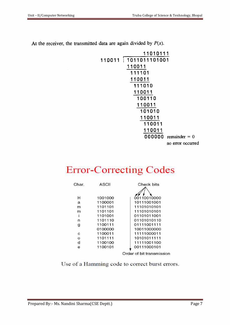
Unit – II/Computer Networking Truba College of Science & Tenhnology, Bhopal
Prepared By:- Ms. Nandini Sharma(CSE Deptt.) Page 7
Unit – II/Computer Networking Truba College of Science & Tenhnology, Bhopal
Prepared By:- Ms. Nandini Sharma(CSE Deptt.) Page 8
Elementary Data link Protocols
The physical layer, data link layer and network layer are independent processes that
communicate by passing message back and forth. In many cases, the physical and DLL
processes will be running on a processor inside a special network I/O chip and the network
layer code will be running on a on the main CPU.
As far as the DLL is concerned, the packet across the interface to it from the network layer is
pure data, whose every bit is to be delivered to the destination’s network layer. The fact that
the destination’s network layer may interpret part of the packet as a header is of no concern to
the DLL.
When the DLL accepts a packet, it encapsulates the packet in a frame by adding a data link
header and trailer to it.
These core functions are necessary for all different types of data protocols.
1. wait_for_event
2. to_network_layer
3. from_network_layer
4. from_physical_layer
5. to_physical_layer
6. start_timer
7. stop_timer
8. start_ack_timer
Unit – II/Computer Networking Truba College of Science & Tenhnology, Bhopal
Prepared By:- Ms. Nandini Sharma(CSE Deptt.) Page 9
9. stop_ack_timer
10. void
11. Kind
Elementary Data Link Protocols
1. An Unrestricted Simplex Protocol : This is an ideal situation. In this simple protocol
the sender keeps sending frames and the receiver keeps receiving frames. No errors ever occur; no re-transmissions are ever needed.
Assumption:
1. Data transmission in one direction only (simplex) 2. No errors take place on the physical channel 3. The sender/receiver can generate/consume an infinite amount of data
4. Always ready for sending/receiving
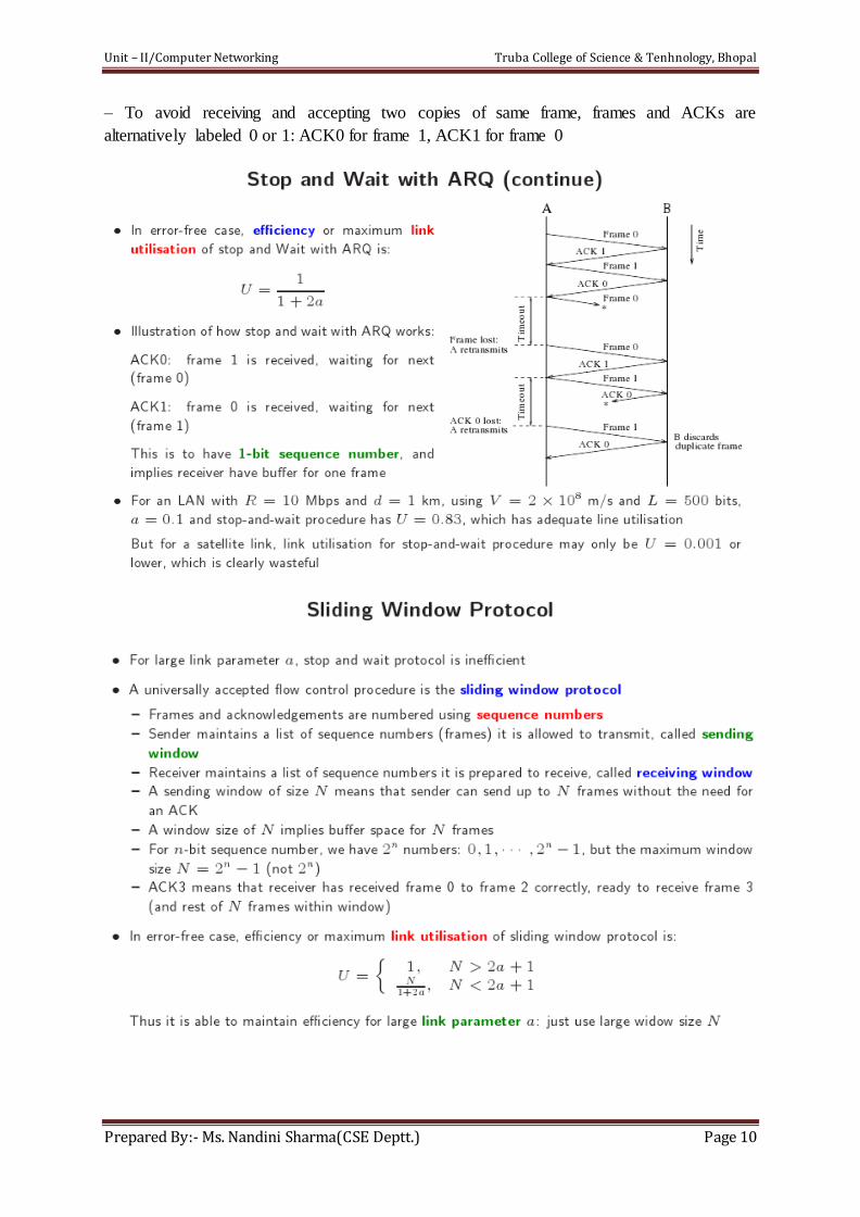
2. A Simplex Stop-and-Wait Protocol: Flow control deals with problem that sender
transmits frames faster than receiver can accept, and solution is to limit sender into
sending no faster than receiver can handle.
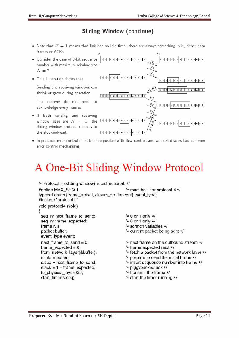
• Consider the simplex case: data is transmitted in one direction (Note although data frames
are transmitted in one direction, frames are going in both directions, i.e. link is duplex) sender
sends
• Stop and wait : one data frame, waits for acknowledgement (ACK) from receiver before
proceeding to transmit next frame
– This simple flow control will breakdown if ACK gets lost or errorsoccur → sender may
wait for ACK that never arrives.
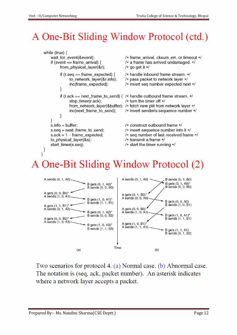
Simplex Stop and Wait with ARQ
• For noisy link, pure stop and wait protocol will break down, and solution is to incorporate
some error control mechanism
• Stop and wait with ARQ: Automatic Repeat reQuest (ARQ), an error control method, is
incorporated with stop and wait flow control protocol
– If error is detected by receiver, it discards the frame and send a negative ACK (NAK),
causing sender to re-send the frame
– In case a frame never got to receiver, sender has a timer: each time a frame is sent, timer is
set
→ If no ACK or NAK is received during timeout period, it re-sends the frame
– Timer introduces a problem: Suppose timeout and sender retransmits a frame but receiver
actually received the previous transmission → receiver has duplicated copies
Unit – II/Computer Networking Truba College of Science & Tenhnology, Bhopal
Prepared By:- Ms. Nandini Sharma(CSE Deptt.) Page 10
– To avoid receiving and accepting two copies of same frame, frames and ACKs are
alternatively labeled 0 or 1: ACK0 for frame 1, ACK1 for frame 0
Unit – II/Computer Networking Truba College of Science & Tenhnology, Bhopal
Prepared By:- Ms. Nandini Sharma(CSE Deptt.) Page 11
Unit – II/Computer Networking Truba College of Science & Tenhnology, Bhopal
Prepared By:- Ms. Nandini Sharma(CSE Deptt.) Page 12
Unit – II/Computer Networking Truba College of Science & Tenhnology, Bhopal
Prepared By:- Ms. Nandini Sharma(CSE Deptt.) Page 13
Unit – II/Computer Networking Truba College of Science & Tenhnology, Bhopal
Prepared By:- Ms. Nandini Sharma(CSE Deptt.) Page 14
Unit – II/Computer Networking Truba College of Science & Tenhnology, Bhopal
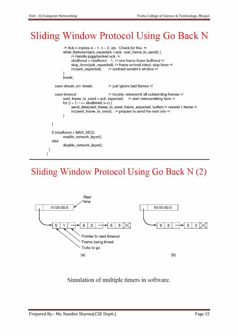
Prepared By:- Ms. Nandini Sharma(CSE Deptt.) Page 15
Unit – II/Computer Networking Truba College of Science & Tenhnology, Bhopal
Prepared By:- Ms. Nandini Sharma(CSE Deptt.) Page 16
Protocol Verification
1. Finite State Machine Models
2. Petri Net Models
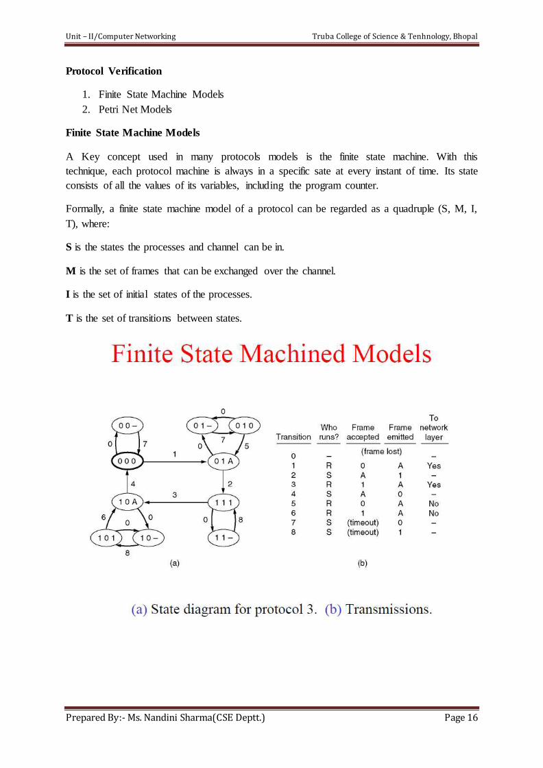
Finite State Machine Models
A Key concept used in many protocols models is the finite state machine. With this
technique, each protocol machine is always in a specific sate at every instant of time. Its state
consists of all the values of its variables, including the program counter.
Formally, a finite state machine model of a protocol can be regarded as a quadruple (S, M, I,
T), where:
S is the states the processes and channel can be in.
M is the set of frames that can be exchanged over the channel.
I is the set of initial states of the processes.
T is the set of transitions between states.
Unit – II/Computer Networking Truba College of Science & Tenhnology, Bhopal
Prepared By:- Ms. Nandini Sharma(CSE Deptt.) Page 17
Unit – II/Computer Networking Truba College of Science & Tenhnology, Bhopal
Prepared By:- Ms. Nandini Sharma(CSE Deptt.) Page 18
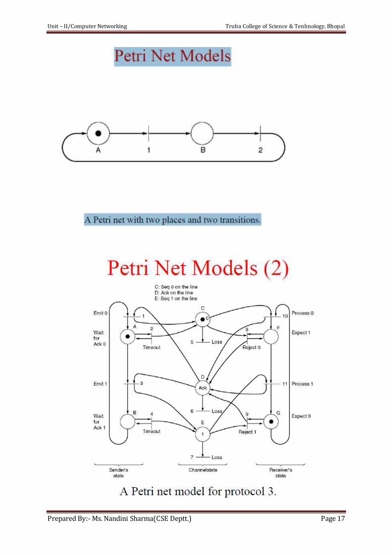
The finite state machine is not the only technique for formally specifying protocols. A Petri
net has four basic elements: places, transitions, arcs, and tokens. A place represents a state
which of the system may be in a figure a Petri net with two places, A and B, both shown as
circles. The system is currently in state A, indicated by the token in place A. A transition is
indicated by a horizontal or vertical bar. Each transitions has zero or more input arcs coming
from its input places, and zero or more output arcs, going to its places.
Unlike the finite state machine model, there are no composite sates here; the sender’s state,
channel state, and receiver’s state are represented separately. Transitions 1 and 2 correspond
to transmission of frame 0 by the sender, normally, and on a timeout respectively. Transitions
3 and 4 are analogous for frame 1. Transitions 5, 6 and 7 correspond to the loss of frame 0, an
acknowledgement, and frame 1, respectively. Transitions 8 and 9 occur when a data frame
with the wrong sequence number arrives at the receiver. Transitions 10 and 11 represent the
arrival at the receiver of the next frame in sequence and its delivery to the network layer.
Petri net can be used to detect protocol failures in a way similar to use of finite state machine.
It can be represented in convenient algebraic form resembling a grammar. The concept of a
deadlock in a Petri net is similar to its finite sate machine counterpart.
Example of Data Link Protocols
1. HDLC- High Level Data Link Control
2. The Data Link Layer in the Internet
High Level Data Link Control
DLL protocol first used in the IBM mainframe world: SDLC (Synchronous Data Link
Control) protocol. After developing SDLC, IBM submitted it to ANSI and ISO for
acceptance as U.S. and international standards, resp. ANSI modified it to become ADCCP
(Advanced Data Communication Control Procedure). CCITT then adopted and modified
HDLC for its LAP (Link Access Procedure) as part of the X.25 network interface standard
but later modified it again to LAPB, to make it more compatible.
The original "normal response mode" is a master-slave mode where the computer
(or primary terminal/Command ) gives each peripheral (secondary terminal/ Response) permission to speak in turn. Because all communication is either to or from the primary
terminal, frames include only one address, that of the secondary terminal; the primary terminal is not assigned an address. There is also a strong distinction between commandssent by the primary to a secondary, and responses sent by a secondary to the primary. Commands
and responses are in fact indistinguishable; the only difference is the direction in which they are transmitted.
Normal response mode allows operation over half-duplex communication links, as long as the primary is aware that it may not transmit when it has given permission to a secondary.
Asynchronous response mode is an HDLC addition for use over full-duplex links. While
retaining the primary/secondary distinction, it allows the secondary to transmit at any time.
Asynchronous balanced mode added the concept of a combined terminal which can act as
both a primary and a secondary. There are some subtleties about this mode of operation;
Unit – II/Computer Networking Truba College of Science & Tenhnology, Bhopal
Prepared By:- Ms. Nandini Sharma(CSE Deptt.) Page 19
while many features of the protocol do not care whether they are in a command or response frame, some do, and the address field of a received frame must be examined to determine
whether it contains a command (the address received is ours) or a response (the address received is that of the other terminal).
Some HDLC variants extend the address field to include both source and destination addresses, or an explicit command/response bit.
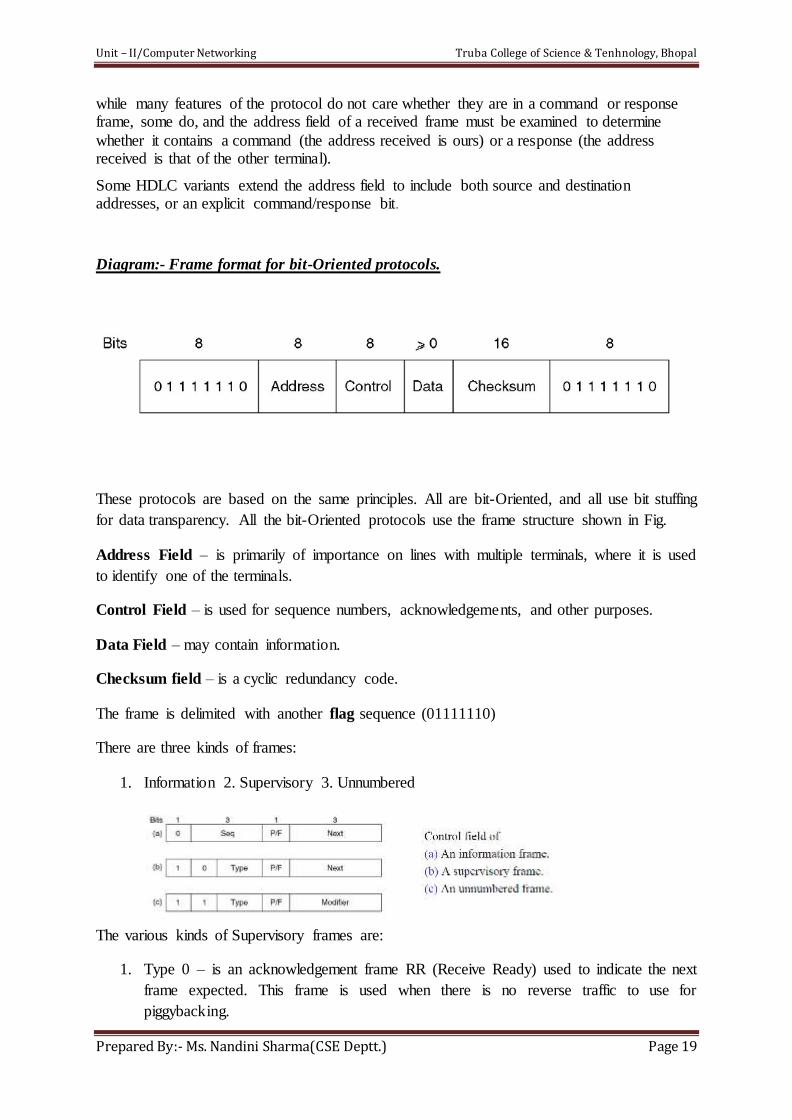
Diagram:- Frame format for bit-Oriented protocols.
These protocols are based on the same principles. All are bit-Oriented, and all use bit stuffing
for data transparency. All the bit-Oriented protocols use the frame structure shown in Fig.
Address Field – is primarily of importance on lines with multiple terminals, where it is used
to identify one of the terminals.
Control Field – is used for sequence numbers, acknowledgements, and other purposes.
Data Field – may contain information.
Checksum field – is a cyclic redundancy code.
The frame is delimited with another flag sequence (01111110)
There are three kinds of frames:
1. Information 2. Supervisory 3. Unnumbered
The various kinds of Supervisory frames are:
1. Type 0 – is an acknowledgement frame RR (Receive Ready) used to indicate the next
frame expected. This frame is used when there is no reverse traffic to use for
piggybacking.
Unit – II/Computer Networking Truba College of Science & Tenhnology, Bhopal
Prepared By:- Ms. Nandini Sharma(CSE Deptt.) Page 20
2. Type 1 – is a –ve acknowledgement frame (Reject). It is used to indicate that a
transmission error has been detected.
3. Type 2 – is Receive Not Ready. It acknowledgement frame up to but not including
Next.
4. Type 3 – is the Selective Reject. It calls for transmission of only the frame specified.
The Data Link Layer in the Internet
The internet consists of individual machines and the communication infrastructures that
connect them. In practice, point-to-point communication is primarily used in two
communications.
First, thousands of organizations have one or more LANs, each with some number of hosts
along with a router. Often, the routers are interconnected by LAN. Typically, all connections
to the outside world go through one or two routers that have point-to-point leased lines to
distant routers.
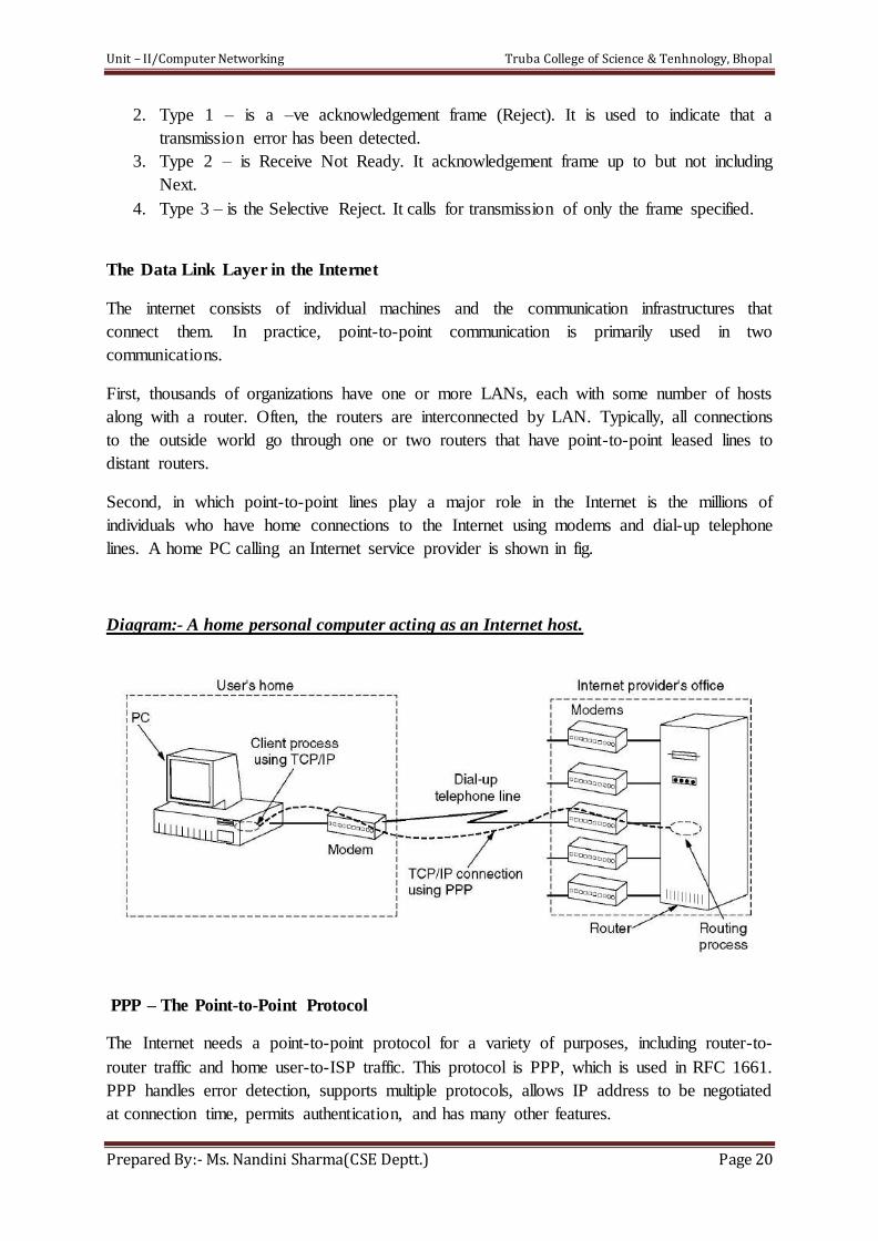
Second, in which point-to-point lines play a major role in the Internet is the millions of
individuals who have home connections to the Internet using modems and dial-up telephone
lines. A home PC calling an Internet service provider is shown in fig.
Diagram:- A home personal computer acting as an Internet host.
PPP – The Point-to-Point Protocol
The Internet needs a point-to-point protocol for a variety of purposes, including router-to-
router traffic and home user-to-ISP traffic. This protocol is PPP, which is used in RFC 1661.
PPP handles error detection, supports multiple protocols, allows IP address to be negotiated
at connection time, permits authentication, and has many other features.
Unit – II/Computer Networking Truba College of Science & Tenhnology, Bhopal
Prepared By:- Ms. Nandini Sharma(CSE Deptt.) Page 21
1. A framing method that unambiguously delineates the end of one frame and the start of
the next one. The frame also handles error detection.
2. A link control protocol for bringing lines up, testing them, negotiating options and
bringing them down again gracefully when they are no longer needed. This protocol is
called LCP (Link Control Protocol). It supports synchronous and asynchronous
circuits and byte-oriented and bit-oriented encodings.
3. A way to negotiate network-layer options in a way that is independent of the network
layer protocol to be used. The method chosen is to have a different NCP (Network
Control Protocol) for each network layer supported.
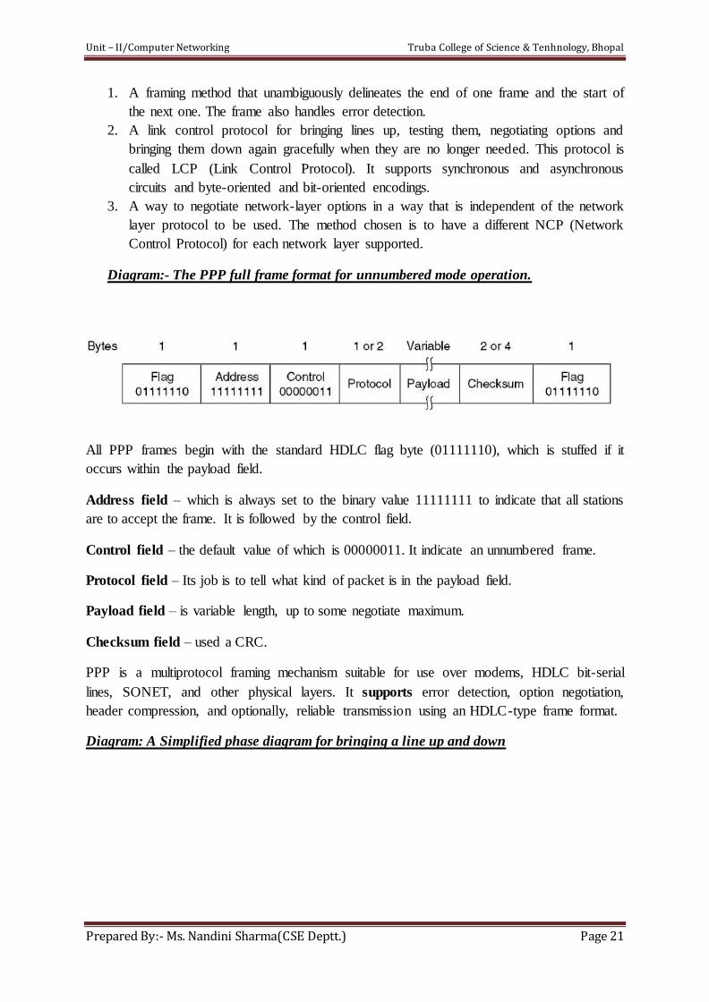
Diagram:- The PPP full frame format for unnumbered mode operation.
All PPP frames begin with the standard HDLC flag byte (01111110), which is stuffed if it
occurs within the payload field.
Address field – which is always set to the binary value 11111111 to indicate that all stations
are to accept the frame. It is followed by the control field.
Control field – the default value of which is 00000011. It indicate an unnumbered frame.
Protocol field – Its job is to tell what kind of packet is in the payload field.
Payload field – is variable length, up to some negotiate maximum.
Checksum field – used a CRC.
PPP is a multiprotocol framing mechanism suitable for use over modems, HDLC bit-serial
lines, SONET, and other physical layers. It supports error detection, option negotiation,
header compression, and optionally, reliable transmission using an HDLC-type frame format.
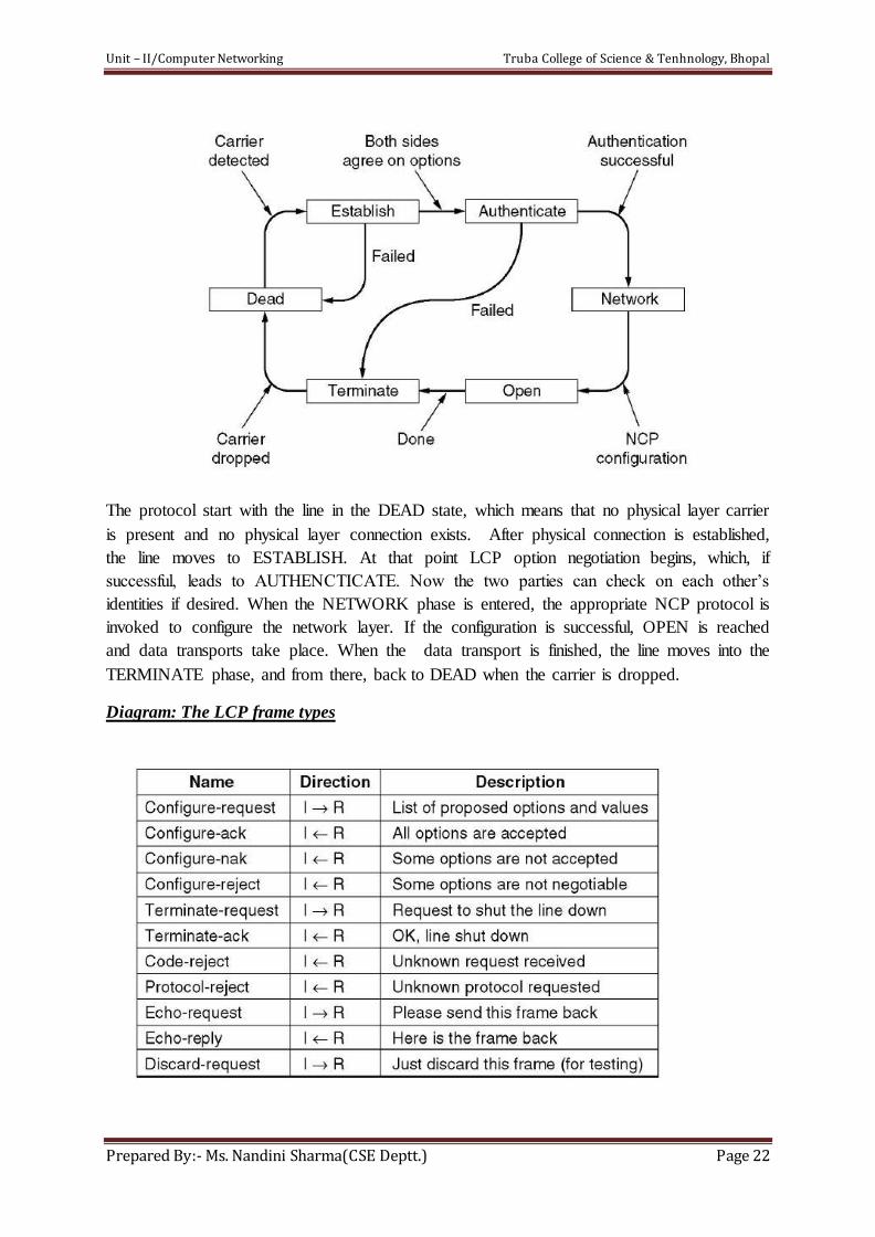
Diagram: A Simplified phase diagram for bringing a line up and down
Unit – II/Computer Networking Truba College of Science & Tenhnology, Bhopal
Prepared By:- Ms. Nandini Sharma(CSE Deptt.) Page 22
The protocol start with the line in the DEAD state, which means that no physical layer carrier
is present and no physical layer connection exists. After physical connection is established,
the line moves to ESTABLISH. At that point LCP option negotiation begins, which, if
successful, leads to AUTHENCTICATE. Now the two parties can check on each other’s
identities if desired. When the NETWORK phase is entered, the appropriate NCP protocol is
invoked to configure the network layer. If the configuration is successful, OPEN is reached
and data transports take place. When the data transport is finished, the line moves into the
TERMINATE phase, and from there, back to DEAD when the carrier is dropped.
Diagram: The LCP frame types
Unit – II/Computer Networking Truba College of Science & Tenhnology, Bhopal
Prepared By:- Ms. Nandini Sharma(CSE Deptt.) Page 23
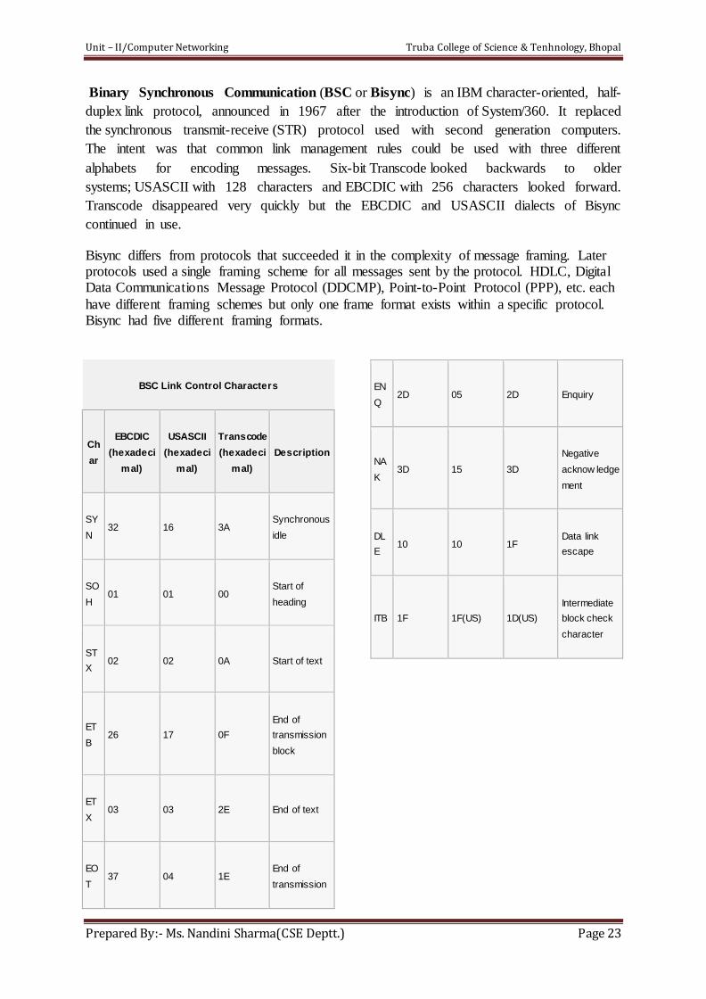
Binary Synchronous Communication (BSC or Bisync) is an IBM character-oriented, half-
duplex link protocol, announced in 1967 after the introduction of System/360. It replaced
the synchronous transmit-receive (STR) protocol used with second generation computers.
The intent was that common link management rules could be used with three different
alphabets for encoding messages. Six-bit Transcode looked backwards to older
systems; USASCII with 128 characters and EBCDIC with 256 characters looked forward.
Transcode disappeared very quickly but the EBCDIC and USASCII dialects of Bisync
continued in use.
Bisync differs from protocols that succeeded it in the complexity of message framing. Later protocols used a single framing scheme for all messages sent by the protocol. HDLC, Digital Data Communications Message Protocol (DDCMP), Point-to-Point Protocol (PPP), etc. each
have different framing schemes but only one frame format exists within a specific protocol. Bisync had five different framing formats.
BSC Link Control Characters
Ch
ar
EBCDIC
(hexadeci
mal)
USASCII
(hexadeci
mal)
Transcode
(hexadeci
mal)
Description
SY
N 32 16 3A
Synchronous
idle
SO
H 01 01 00
Start of
heading
ST
X 02 02 0A Start of text
ET
B 26 17 0F
End of
transmission
block
ET
X 03 03 2E End of text
EO
T 37 04 1E
End of
transmission
EN
Q 2D 05 2D Enquiry
NA
K 3D 15 3D
Negative
acknow ledge
ment
DL
E 10 10 1F
Data link
escape
ITB 1F 1F(US) 1D(US)
Intermediate
block check
character
Unit – II/Computer Networking Truba College of Science & Tenhnology, Bhopal
Prepared By:- Ms. Nandini Sharma(CSE Deptt.) Page 24
Bridges
A network bridge connects multiple network segments at the data link layer (layer 2) of the OSI model. Bridges broadcast to all ports except the port on which the broadcast was received. However, bridges do not promiscuously copy traffic to all ports, as hubs do, but learn which MAC addresses are reachable through specific ports. Once the bridge associates a port and an address, it will send traffic for that address to that port only.
Bridges learn the association of ports and addresses by examining the source address of frames that it sees on various ports. Once a frame arrives through a port, its source address is stored and the bridge assumes that MAC address is associated with that port. The first time that a previously unknown destination address is seen, the bridge will forward the frame to all ports other than the one on which the frame arrived.
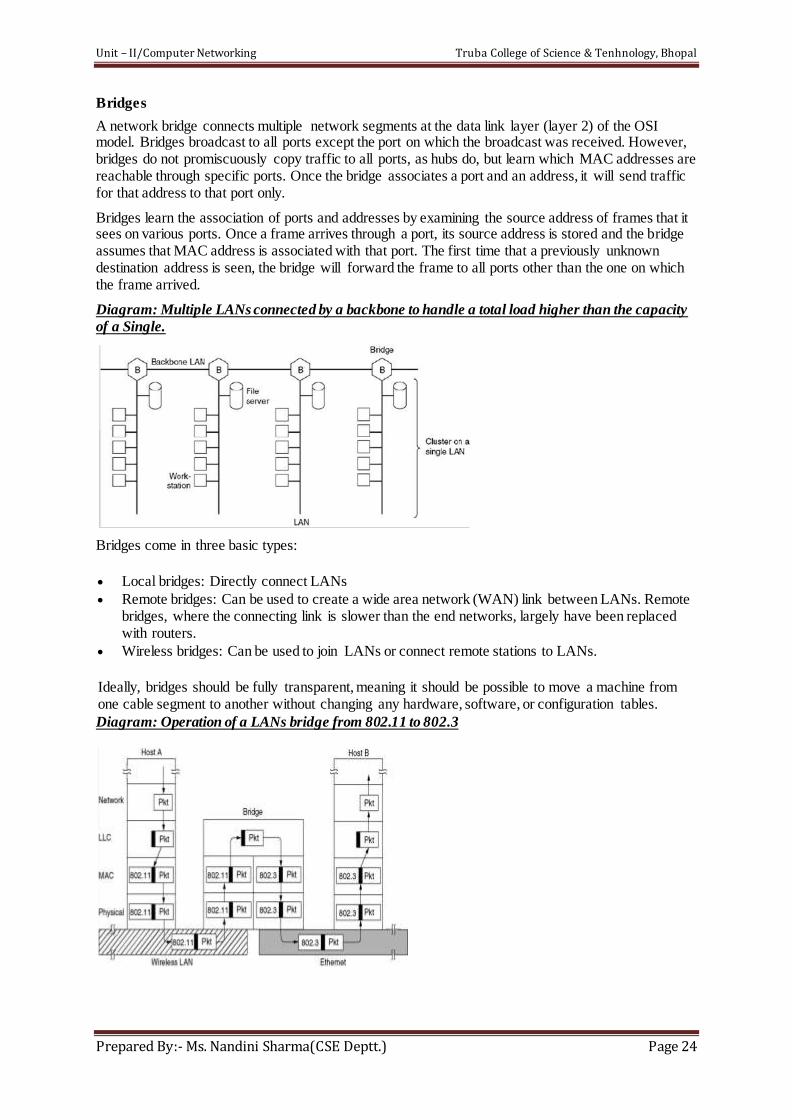
Diagram: Multiple LANs connected by a backbone to handle a total load higher than the capacity
of a Single.
Bridges come in three basic types:
Local bridges: Directly connect LANs
Remote bridges: Can be used to create a wide area network (WAN) link between LANs. Remote bridges, where the connecting link is slower than the end networks, largely have been replaced with routers.
Wireless bridges: Can be used to join LANs or connect remote stations to LANs.
Ideally, bridges should be fully transparent, meaning it should be possible to move a machine from one cable segment to another without changing any hardware, software, or configuration tables.
Diagram: Operation of a LANs bridge from 802.11 to 802.3
Unit – II/Computer Networking Truba College of Science & Tenhnology, Bhopal
Prepared By:- Ms. Nandini Sharma(CSE Deptt.) Page 25
Local Internetworking
In large organizations with many LANs, just interconnecting them all raises a variety of issues, even
if they are all just ethernet. Ideally, it should be possible to go out and buy bridges designed to the
IEEE standard, plug the connectors into the bridges, and evrything should work perfectly, instantly.
There should be no hardware and software changes required. In other words, the bridges should be
completely transparent. v
The routing procedure for an incoming frame depends on the LAN it arrives on (the source LAN) and
the LAN its destination is on (the destination LAN) as follows:
1. If destiantion and source LANs are the same, discard the frame.
2. If destiantion and source LANs are the different, forward the frame.
3. If destiantion LANs is unknown, use flooding.
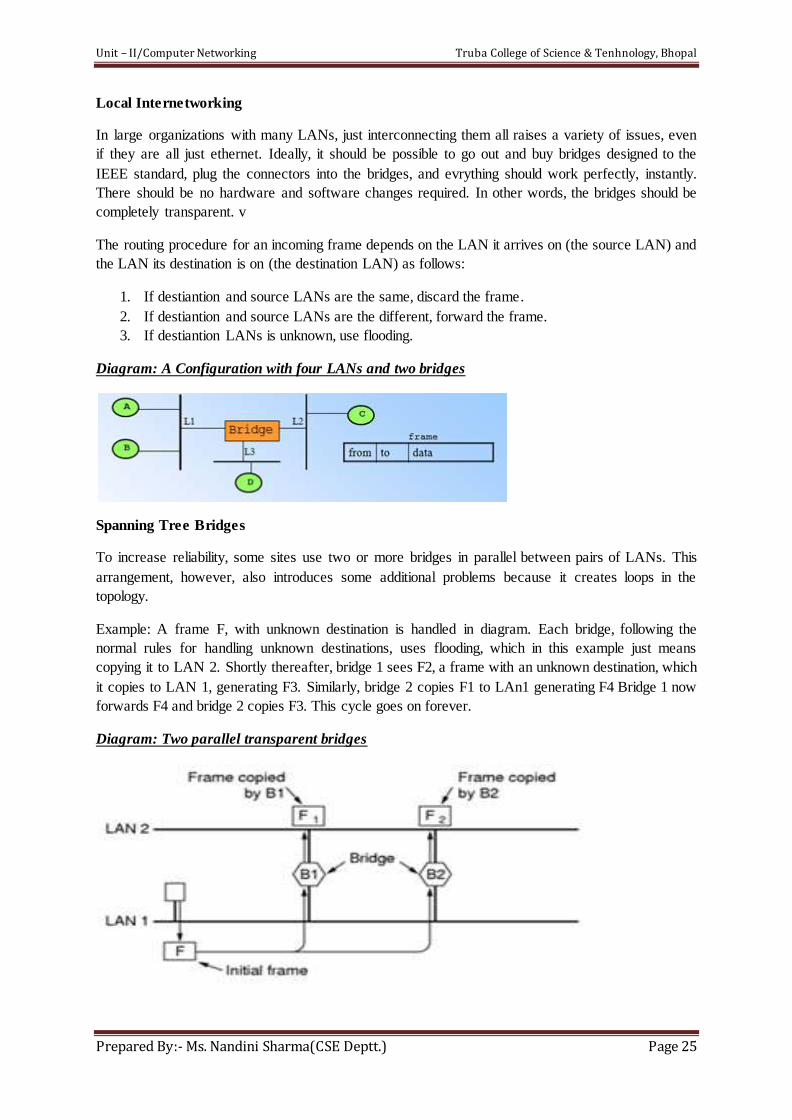
Diagram: A Configuration with four LANs and two bridges
Spanning Tree Bridges
To increase reliability, some sites use two or more bridges in parallel between pairs of LANs. This
arrangement, however, also introduces some additional problems because it creates loops in the
topology.
Example: A frame F, with unknown destination is handled in diagram. Each bridge, following the
normal rules for handling unknown destinations, uses flooding, which in this example just means
copying it to LAN 2. Shortly thereafter, bridge 1 sees F2, a frame with an unknown destination, which
it copies to LAN 1, generating F3. Similarly, bridge 2 copies F1 to LAn1 generating F4 Bridge 1 now
forwards F4 and bridge 2 copies F3. This cycle goes on forever.
Diagram: Two parallel transparent bridges
Unit – II/Computer Networking Truba College of Science & Tenhnology, Bhopal
Prepared By:- Ms. Nandini Sharma(CSE Deptt.) Page 26
The Solution to this difficulty is for the bridges to communicate with each other and overlay the actual
topology with a spanning tree that reaches every interests of constructing a fictitious loop-free
topology.
The result of this algorithm is that a unique path is established from every LAN to the root and thus to
every other LAN.
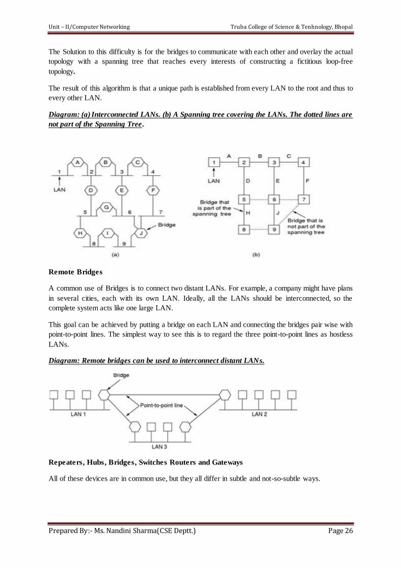
Diagram: (a) Interconnected LANs. (b) A Spanning tree covering the LANs. The dotted lines are
not part of the Spanning Tree.
Remote Bridges
A common use of Bridges is to connect two distant LANs. For example, a company might have plans
in several cities, each with its own LAN. Ideally, all the LANs should be interconnected, so the
complete system acts like one large LAN.
This goal can be achieved by putting a bridge on each LAN and connecting the bridges pair wise with
point-to-point lines. The simplest way to see this is to regard the three point-to-point lines as hostless
LANs.
Diagram: Remote bridges can be used to interconnect distant LANs.
Repeaters, Hubs, Bridges, Switches Routers and Gateways
All of these devices are in common use, but they all differ in subtle and not-so-subtle ways.

Unit – II/Computer Networking Truba College of Science & Tenhnology, Bhopal
Prepared By:- Ms. Nandini Sharma(CSE Deptt.) Page 27
The layer matters because different devices use different pieces of information to decide how to
switch. In a typical scenario, the user generates some data to be sent to a remote machine. Those data
are passed to the transport layer, with then adds a header.
Diagram: (a) Which device is in which layer (b) Frames, packets and headers
Diagram: (a)A Hub (b) A Bridge (c) A Switch
Recommended


![COMPUTER NETWORK UNIT-I - rgpvonline.com · COMPUTER NETWORK UNIT-I Lecture-1 Computer Network: Definitions [RGPV June 2013] A computer network or data network is a …](https://img.pdfslide.us/doc/110x75/5b0418927f8b9a0a548d0f9a/computer-network-unit-i-network-unit-i-lecture-1-computer-network-definitions.jpg)

![Defining Open Authority: Museum Computer Network 2013 [NOTES]](https://img.pdfslide.us/doc/110x75/5554329fb4c905987e8b5179/defining-open-authority-museum-computer-network-2013-notes.jpg)