THIRUMALAI ENGINEERING COLLEGE
KILAMBI, KANCHIPURAM-631551
DEPARTMENT OF COMPUTER SCIENCE AND ENGINEERING
COMPUTER GRAPHICS LAB(CS 2405)
NAME : _________________________________
REG. NUMBER : _________________________________
SEMESTER : _________________________________
YEAR : ___________________________________

THIRUMALAI ENGINEERING COLLEGE
KILAMBI, KANCHIPURAM-631551
DEPARTMENT OF COMPUTER SCIENCE AND ENGINEERING
BONAFIDE CERTIFICATE
This is to certify that this is a bonafide work done by
Mr./Miss.______________________________ Reg.No._____________________
For the CS 2405 – Computer Graphics Lab as a part of B.E., Computer Science
and Engineering course in Thirumalai Engineering College, Kanchipuram during
the year of 2013-2014. The Record is found to be completed and satisfactory.
Head of the Department Staff In-Charge
Submitted for the Practical Examination held on ________________
Internal Examiner External Examiner

S.NO.
DATE NAME OF THE EXPERIMENTPAGE
NOSIGN
1.IMPLEMENTATION OF BRESENHAMS LINE,
CIRCLE AND ELLIPSE DRAWING ALGORITHM
2.IMPLEMENTATION OF LINE, CIRCLE AND
ELLIPSE ATTRIBUTES
3.IMPLEMENTATION OF TWO DIMENSIONAL
TRANSFORMATIONS
4.IMPLEMENTATION OF COMPOSITE TWO
DIMENSIONAL TRANSFORMATIONS
5.IMPLEMENTATION OF COHEN
SUTHERLAND TWO DIMENSIONAL LINE CLIPPING
6.IMPLEMENTATION OF SUTHERLAND
HODGEMAN POLYGON CLIPPING
7.IMPLEMENTATION OF THREE
DIMENSIONAL TRANSFORMATIONS
8.IMPLEMENTATION OF COMPOSITE THREE
DIMENSIONAL TRANSFORMATIONS
9.(a) DRAWING THREE DIMENSIONAL OBJECTS
9.(b) DRAWING THREE DIMENSIONAL SCENES
10. FRACTALS
LIST OF EXPERIMENTS
EX.NO:IMPLEMENTATION OF BRESENHAMS LINE DRAWING
ALGORITHMDATE:
AIM: To write a program for implementation of Bresenhams line Drawing Algorithm.
ALGORITHM:
Start the program
Include the graphics header file and obtain graphics mode and driver.
Get the co-ordinates of two end points of a line (x1,y1) & (x2,y2) and store left end point in (X1,
y1).
Load (x1, y1) into frame buffer that means plot the first point.
Calculate constants dx, dy, 2dy, 2dy-2dx and obtain value for decision parameter p=2dy-dx.
At each x along the line perform the test if p<0, next point to plot is (x+1,y) and p+1=p+2dy
Otherwise (x+1, y+1) & p+1=p+2dy-2dx
Repeat steps dx times.
Display a BresenHam’s Line Drawing
Stop the program.
PROGRAM:
#include<stdio.h>#include<conio.h>#include<graphics.h>#include<math.h>#include<stdlib.h>#include<dos.h>void bres(int,int,int,int);void main(){int x1,y1,x2,y2;initgraph(&gd,&gm,"d:\\tc\\BGI");clrscr();printf("\nEnter the string and encoding coordinates:");scanf("%d%d%d%d",&x1,&y1,&x2,&y2);
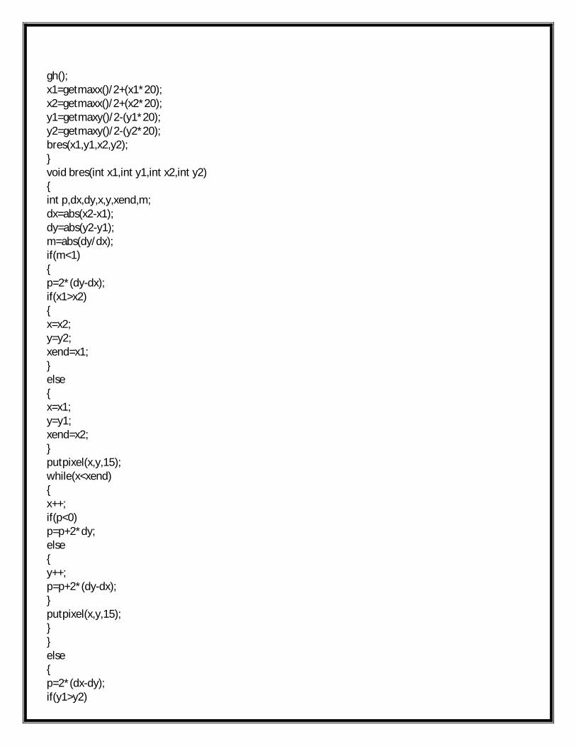
gh();x1=getmaxx()/2+(x1*20);x2=getmaxx()/2+(x2*20);y1=getmaxy()/2-(y1*20);y2=getmaxy()/2-(y2*20);bres(x1,y1,x2,y2);}void bres(int x1,int y1,int x2,int y2){int p,dx,dy,x,y,xend,m;dx=abs(x2-x1);dy=abs(y2-y1);m=abs(dy/dx);if(m<1){p=2*(dy-dx);if(x1>x2){x=x2;y=y2;xend=x1;}else{x=x1;y=y1;xend=x2;}putpixel(x,y,15);while(x<xend){x++;if(p<0)p=p+2*dy;else{y++;p=p+2*(dy-dx);}putpixel(x,y,15);}}else{p=2*(dx-dy);if(y1>y2)
{x=x2;
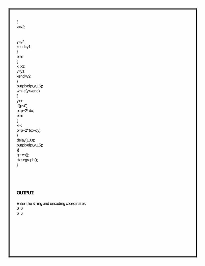
y=y2;xend=y1;}else{x=x1;y=y1;xend=y2;}putpixel(x,y,15);while(y<xend){y++;if(p<0)p=p+2*dx;else{x--;p=p+2*(dx-dy);}delay(100);putpixel(x,y,15);}}getch();closegraph();}
OUTPUT:
Enter the string and encoding coordinates:0 06 6
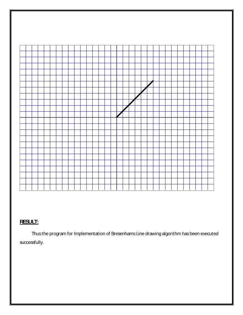
RESULT: Thus the program for Implementation of Bresenhams Line drawing algorithm has been executed
successfully.

EX.NO:IMPLEMENTATION OF BRESENHAMS CIRCLE DRAWING
ALGORITHMDATE:
AIM: To write a program for implementation of Bresenhams Circle Drawing Algorithm.
ALGORITHM:
Start the program
Include the graphics header file and obtain graphics mode and driver.
Get the center point (x,y) and radius(r) of a circle.
Initialize the variables
Select f the following in circle, ddsym and Flower
Plot the pixel to display the circle using put pixel function.
Display the BRESENHAM’S CIRCLE DRAWING ALGORITHM
Stop the program
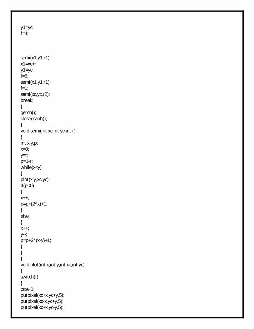
PROGRAM:
#include<stdio.h>#include<conio.h>#include<math.h>#include<graphics.h>void plot(int,int,int,int);int f;void main(){int ch,r,xc,yc,x,y,x1,y1,x2,y2,r1,r2;float p;initgraph(&gd,&gm,"d:\\tc\\BGI");void plot(int x,int y,int xc,int yc);void semi(int xc,int yc,int r);printf("\nEnter the Center and radius:");printf("\nXcenter:");scanf("%d",&xc);printf("Ycenter:");scanf("%d",&yc);printf("Radius:");
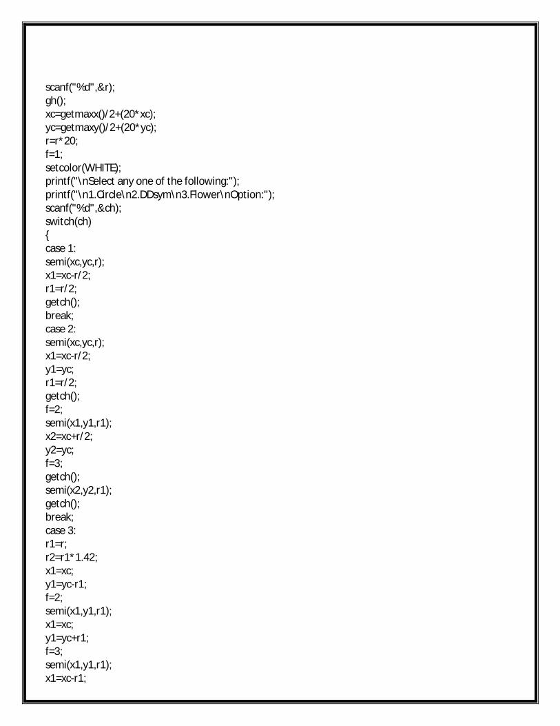
scanf("%d",&r);gh();xc=getmaxx()/2+(20*xc);yc=getmaxy()/2+(20*yc);r=r*20;f=1;setcolor(WHITE);printf("\nSelect any one of the following:");printf("\n1.Circle\n2.DDsym\n3.Flower\nOption:");scanf("%d",&ch);switch(ch){case 1:semi(xc,yc,r);x1=xc-r/2;r1=r/2;getch();break;case 2:semi(xc,yc,r);x1=xc-r/2;y1=yc;r1=r/2;getch();f=2;semi(x1,y1,r1);x2=xc+r/2;y2=yc;f=3;getch();semi(x2,y2,r1);getch();break;case 3:r1=r;r2=r1*1.42;x1=xc;y1=yc-r1;f=2;semi(x1,y1,r1);x1=xc;y1=yc+r1;f=3;semi(x1,y1,r1);x1=xc-r1;
y1=yc;f=4;
semi(x1,y1,r1);x1=xc+r;y1=yc;f=5;semi(x1,y1,r1);f=1;semi(xc,yc,r2);break;}getch();closegraph();}void semi(int xc,int yc,int r){int x,y,p;x=0;y=r;p=1-r;while(x<y){plot(x,y,xc,yc);if(p<0){x++;p=p+(2*x)+1;}else{x++;y--;p=p+2*(x-y)+1;}}}void plot(int x,int y,int xc,int yc){switch(f){case 1:putpixel(xc+x,yc+y,5);putpixel(xc-x,yc+y,5);putpixel(xc+x,yc-y,5);
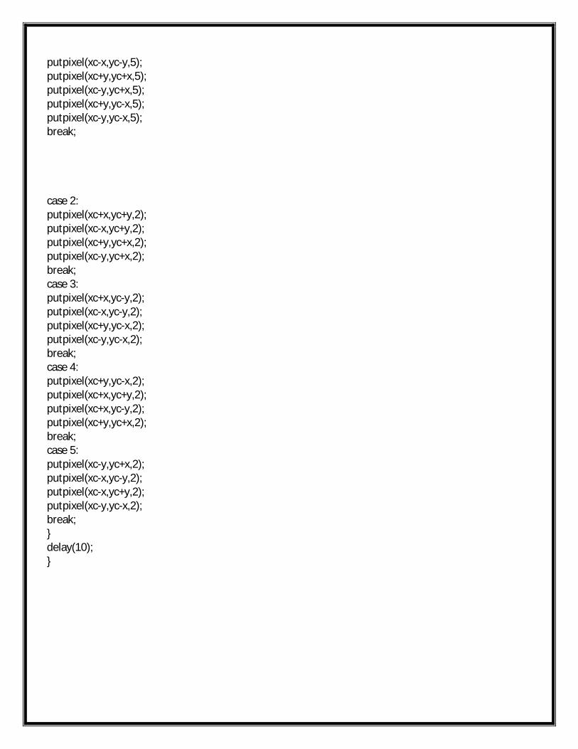
putpixel(xc-x,yc-y,5);putpixel(xc+y,yc+x,5);putpixel(xc-y,yc+x,5);putpixel(xc+y,yc-x,5);putpixel(xc-y,yc-x,5);break;
case 2:putpixel(xc+x,yc+y,2);putpixel(xc-x,yc+y,2);putpixel(xc+y,yc+x,2);putpixel(xc-y,yc+x,2);break;case 3:putpixel(xc+x,yc-y,2);putpixel(xc-x,yc-y,2);putpixel(xc+y,yc-x,2);putpixel(xc-y,yc-x,2);break;case 4:putpixel(xc+y,yc-x,2);putpixel(xc+x,yc+y,2);putpixel(xc+x,yc-y,2);putpixel(xc+y,yc+x,2);break;case 5:putpixel(xc-y,yc+x,2);putpixel(xc-x,yc-y,2);putpixel(xc-x,yc+y,2);putpixel(xc-y,yc-x,2);break;}delay(10);}
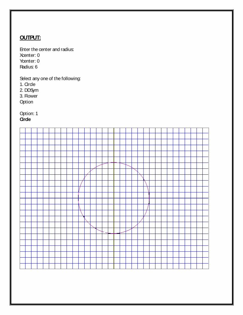
OUTPUT:
Enter the center and radius:Xcenter: 0Ycenter: 0Radius: 6
Select any one of the following:1. Circle2. DDSym3. FlowerOption
Option: 1Circle
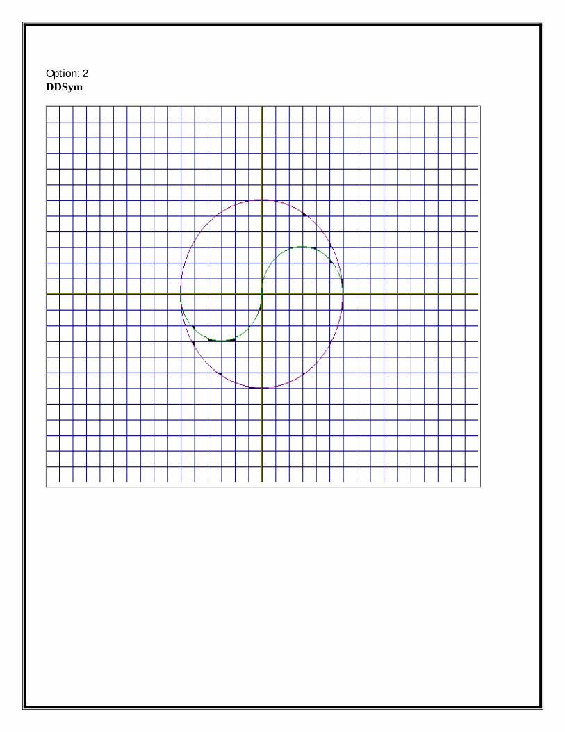
Option: 2DDSym
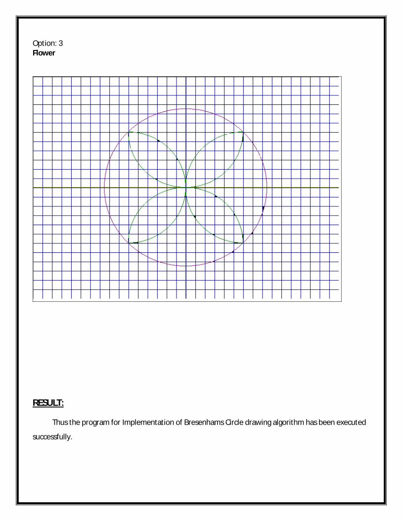
Option: 3Flower
RESULT: Thus the program for Implementation of Bresenhams Circle drawing algorithm has been executed
successfully.
EX.NO:IMPLEMENTATION OF BRESENHAMS ELLIPSE DRAWING
ALGORITHMDATE:
AIM:
To write the program for implementation of Bresenhams Ellipse Drawing Algorithm.
ALGORITHM:
Start the program
Include graphics header file and obtain the graphics mode and driver
Get the radius and center point of the ellipse
Initialize the variables
Calculate the value for d1=rysq-rxsq*ry+(0.25*rxsq)
Plot the pixel to display the ellipse by using put pixel function
Calculate the value for d2, if the value d2>0 then calculate d2=d2-dy+rxsq else d2=d2+dx-dy+rxsq
Close the graph function
Stop the program
PROGRAM:
#include<stdio.h>#include<graphics.h>#include<math.h>void main(){long d1,d2;int i,gd,gm,x,y,x0,y0;long rx,ry,rxsq,rysq,tworxsq,tworysq,dx,dy;initgraph(&gd,&gm,"d:\\tc\\BGI");clrscr();printf("Enter the X radius and Y radius of the ellipse:\n");scanf("%ld%ld",&rx,&ry);printf("\nEnter the center (x,y) of the ellipse:\n");scanf("%d%d",&x0,&y0);detectgraph(&gd,&gm);initgraph(&gd,&gm,"d:\\tc\\BGI");cleardevice();
rxsq=rx*rx;rysq=ry*ry;tworxsq=2*rxsq;tworysq=2*rysq;x=0;y=ry;d1=rysq-rxsq*ry+(0.25*rxsq);dx=tworysq*x;dy=tworxsq*y;do{putpixel(x0+x,y0+y,15);putpixel(x0-x,y0-y,15);putpixel(x0+x,y0-y,15);putpixel(x0-x,y0+y,15);if(d1<0){x=x+1;y=y;dx=dx+tworysq;d1=d1+dx+rysq;}else{x=x+1;y=y-1;dx=dx+tworysq;dy=dy-tworxsq;d1=d1+dx-dy+rysq;}delay(10);}while(dx<dy);d2=rysq*(x+0.5)*(x+0.5)+rxsq*(y-1)*(y-1)-(rxsq*rysq);do{putpixel(x0+x,y0+y,15);putpixel(x0-x,y0-y,15);putpixel(x0+x,y0-y,15);putpixel(x0-x,y0+y,15);if(d2>0){x=x;y=y-1;
dy=dy-tworxsq;d2=d2-dy+rxsq;}else{x=x+1;y=y-1;dx=dx+tworysq;dy=dy-tworxsq;d2=d2+dx-dy+rxsq;}}while(y>0);getch();closegraph();}
OUTPUT:
Enter the X radius and Y radius of the ellipse:7550
Enter the center (x, y) of the ellipse:300300
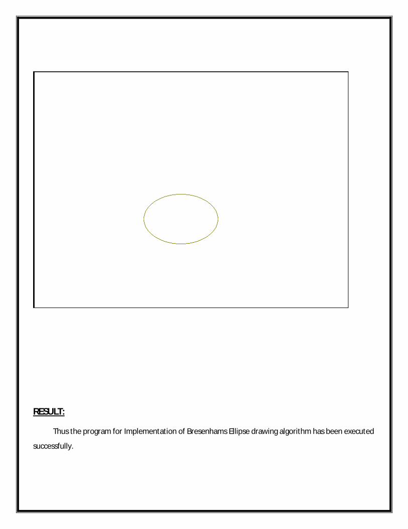
RESULT: Thus the program for Implementation of Bresenhams Ellipse drawing algorithm has been executed
successfully.
EX.NO:IMPLEMENTATION OF LINE, CIRCLE AND ELLIPSE
ATTRIBUTESDATE:
AIM:
To write a program for implementation of Line, Circle and Ellipse Attributes.
ALGORITHM:
Start the program
Create the program for graph.c
Include the graphics header file and get the graphics mode and driver
Create the function gh()
Include the file graph.c in attribute program
Initialize the array variables
Get the values for rectangle by using rectangle function
Get the values for polygon by using drawpoly() function
Get the values for circle and using pieslice() function
Draw star and star flower with using pieslice() function
Stop the program
PROGRAM:
#include<stdio.h>#include<graphics.h>void main(){int x1,y1,a,b;int r[15],r1[19];int poly[]={105,380,155,380,180,330,130,280,80,330,105,380};int r2[]={260,225,380,225,280,300,320,180,360,300,260,225};int r3[]={320,340,420,190,220,190,320,340};int r4[]={220,290,420,290,320,140,220,290};int r5[]={285,190,355,190,385,240,355,290,285,290,255,240};
int r6[]={305,225,335,225,345,255,320,270,295,255,305,225};int r7[]={500,160,540,120,500,80,460,120,500,160};
//RECTANGLErectangle(50,180,200,90);setfillstyle(HATCH_FILL,11);bar(50,180,200,90);getch();//SQUAREsetcolor(GREEN);rectangle(440,180,560,60);setfillstyle(CLOSE_DOT_FILL,GREEN);bar(440,180,560,60);setcolor(16);line(440,180,560,60);line(440,60,560,180);a=(int)(560-440)/3;r[0]=440+a;r[1]=180;r[2]=440;r[3]=180-a;r[4]=560-a;r[5]=60;r[6]=560;r[7]=60+a;r[8]=440+a;r[9]=180;setcolor(BROWN);drawpoly(5,r);setfillstyle(CLOSE_DOT_FILL,BROWN);fillpoly(5,r);r1[0]=560-a;r1[1]=180;r1[2]=560;r1[3]=180-a;r1[4]=440+a;r1[5]=60;r1[6]=440;r1[7]=60+a;r1[8]=560-a;r1[9]=180;setcolor(15);drawpoly(5,r1);setfillstyle(CLOSE_DOT_FILL,15);fillpoly(5,r1);
setfillstyle(HATCH_FILL,RED);fillpoly(5,r7);getch();//POLYGONsetcolor(YELLOW);drawpoly(6,poly);setfillstyle(1,RED);fillpoly(6,poly);line(130,380,130,280);line(130,380,180,330);line(130,380,80,330);line(130,380,105,305);line(130,380,155,305);line(130,380,93,355);line(130,380,168,355);getch();//CIRCLEsetfillstyle(9,DARKGRAY);setcolor(BROWN);pieslice(500,330,0,360,66);setcolor(5);rectangle(480,268,520,393);rectangle(460,278,540,382);rectangle(438,350,562,310);rectangle(448,370,552,290);rectangle(500,395,500,265);rectangle(435,330,565,330);getch();//STARsetfillstyle(1,10);drawpoly(6,r2);fillpoly(6,r2);setfillstyle(9,4);fillpoly(5,r6);setcolor(BLACK);line(180,225,260,225);getch();//STAR FLOWERdrawpoly(4,r3);setfillstyle(1,9);setcolor(9);fillpoly(4,r3);drawpoly(4,r4);setfillstyle(1,GREEN);setcolor(GREEN);
fillpoly(4,r4);setfillstyle(1,5);setcolor(5);pieslice(285,190,55,180,65);setfillstyle(1,6);setcolor(6);pieslice(355,190,0,123,65);setfillstyle(1,5);setcolor(5);pieslice(385,240,303,360,65);pieslice(385,240,0,55,65);setcolor(5);line(385,240,449,240);setfillstyle(1,5);setcolor(5);pieslice(355,290,236,360,65);setfillstyle(1,5);setcolor(5);pieslice(285,290,180,305,65);setfillstyle(1,6);setcolor(6);pieslice(255,240,125,235,65);setfillstyle(9,RED);setcolor(RED);fillpoly(6,r5);getch();}
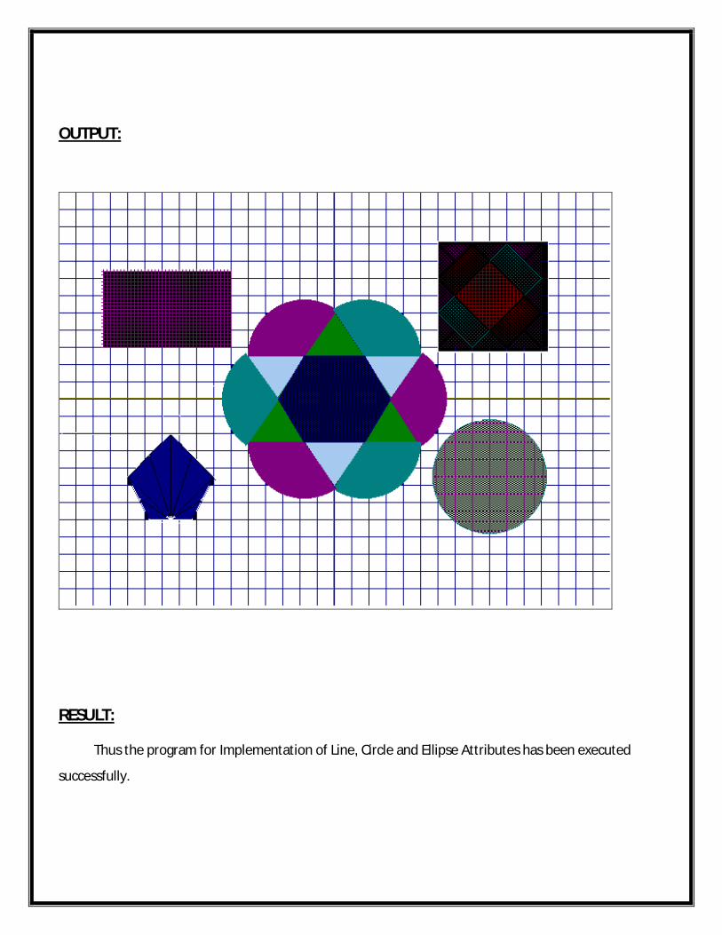
OUTPUT:
RESULT: Thus the program for Implementation of Line, Circle and Ellipse Attributes has been executed
successfully.
EX.NO:IMPLEMENTATION OF TWO DIMENSIONAL
TRANSFORMATIONSDATE:
AIM:
To write a program for implementation of Two Dimensional Transformations.
ALGORITHM:
Start the program.
Include the graphics header file in 2D Transformation.
Declare the function for input, output, shearing, reflection and translation, scaling, rotation.
Initialize the values and get the graphics mode and driver.
In input function get the co-ordinates point.
In translation function get the translation vector tx,ty .
In rotation function get the angle and pivot point fx,fy for rotation.
Get the scaling factor sx,sy in scaling function and also for shearing.
Define the function for reflection.
Stop the program.
PROGRAM:
#include<stdio.h>#include<conio.h>#include<graphics.h>#include<dos.h>#include<math.h>#include<stdlib.h>void menu();void input();void output();void shearing();void reflection();void translation();void scaling();void rotation();

int a[10][2],i,x,option,temp,angle,tx,ty,fx,fy,sh,k,n,axis,y;float sx,sy;void main(){int gd=DETECT,gm;initgraph(&gd,&gm," ");menu();getch();}void menu(){printf("Menu\n");printf("1.Translation\n2.Rotation\n3.Scaling\n4.Shearing\n5.Reflection\n6.Exit\nEnter your choice:");scanf("%d",&option);switch(option){case 1:input();translation();break;case 2:input();rotation();break;case 3:input();scaling();break;case 4:input();shearing();break;case 5:input();reflection();break;case 6:exit(0);break;}}void input(){printf("\nEnter the number of vertices:");scanf("%d",&n);
for(i=0;i<n;i++){printf("Enter the co-ordinates:");scanf("%d%d%d%d",&a[i][0],&a[i][1],&a[i+1][0],&a[i+1][1]);}}void output(){cleardevice();for(i=0;i<n;i++){line(a[i][0],a[i][1],a[i+1][0],a[i+1][1]);}}void translation(){output();printf("Enter the translation vertex tx,ty:\n");scanf("%d%d",&tx,&ty);for(i=0;i<=n;i++){a[i][0]=a[i][0]+tx;a[i][1]=a[i][1]+ty;}output();delay(10);menu();}void rotation(){output();printf("Enter the rotation angle:\n");scanf("%d",&y);printf("Enter the pivot points:");scanf("%d%d",&fx,&fy);k=(y*3.14)/180;for(i=0;i<=n;i++){a[i][0]=fx+(a[i][0]-fx)*cos(k)-(a[i][1]-fy)*sin(k);a[i][1]=fy+(a[i][0]-fx)*sin(k)-(a[i][1]-fy)*cos(k);}output();delay(10);menu();}
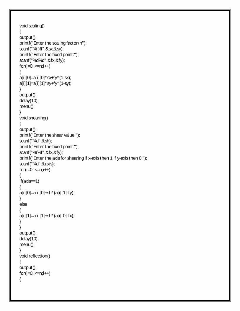
void scaling(){output();printf("Enter the scaling factor\n");scanf("%f%f",&sx,&sy);printf("Enter the fixed point:");scanf("%d%d",&fx,&fy);for(i=0;i<=n;i++){a[i][0]=a[i][0]*sx+fy*(1-sx);a[i][1]=a[i][1]*sy+fy*(1-sy);}output();delay(10);menu();}void shearing(){output();printf("Enter the shear value:");scanf("%d",&sh);printf("Enter the fixed point:");scanf("%f%f",&fx,&fy);printf("Enter the axis for shearing if x-axis then 1,if y-axis then 0:");scanf("%d",&axis);for(i=0;i<=n;i++){if(axis==1){a[i][0]=a[i][0]+sh*(a[i][1]-fy);}else{a[i][1]=a[i][1]+sh*(a[i][0]-fx);}}output();delay(10);menu();}void reflection(){output();for(i=0;i<=n;i++){
temp=a[i][0];a[i][0]=a[i][1];a[i][1]=temp;}output();delay(10);menu();}
OUTPUT:
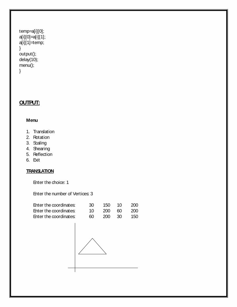
Menu
1. Translation2. Rotation3. Scaling4. Shearing5. Reflection6. Exit
TRANSLATION
Enter the choice: 1
Enter the number of Vertices: 3
Enter the coordinates: 30 150 10 200Enter the coordinates: 10 200 60 200Enter the coordinates: 60 200 30 150
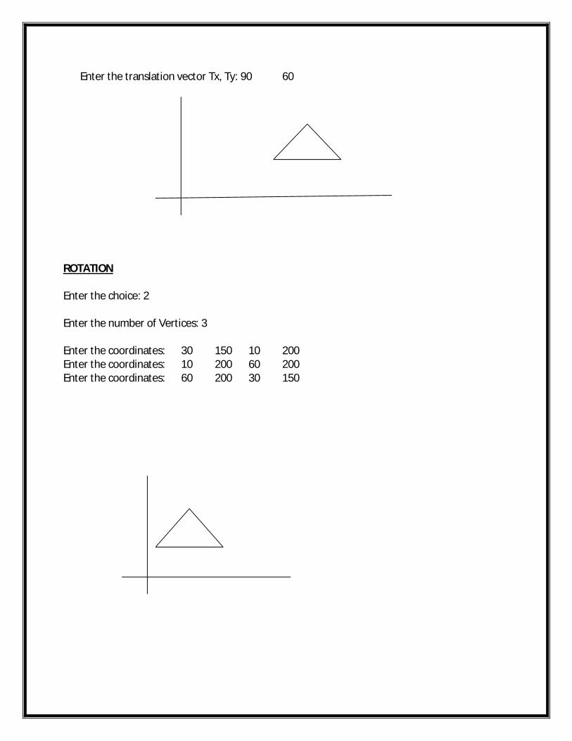
Enter the translation vector Tx, Ty: 90 60
ROTATION
Enter the choice: 2
Enter the number of Vertices: 3
Enter the coordinates: 30 150 10 200Enter the coordinates: 10 200 60 200Enter the coordinates: 60 200 30 150
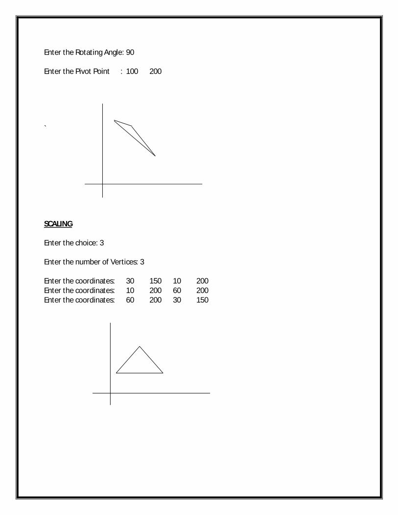
Enter the Rotating Angle: 90
Enter the Pivot Point : 100 200
`
SCALING
Enter the choice: 3
Enter the number of Vertices: 3
Enter the coordinates: 30 150 10 200Enter the coordinates: 10 200 60 200Enter the coordinates: 60 200 30 150
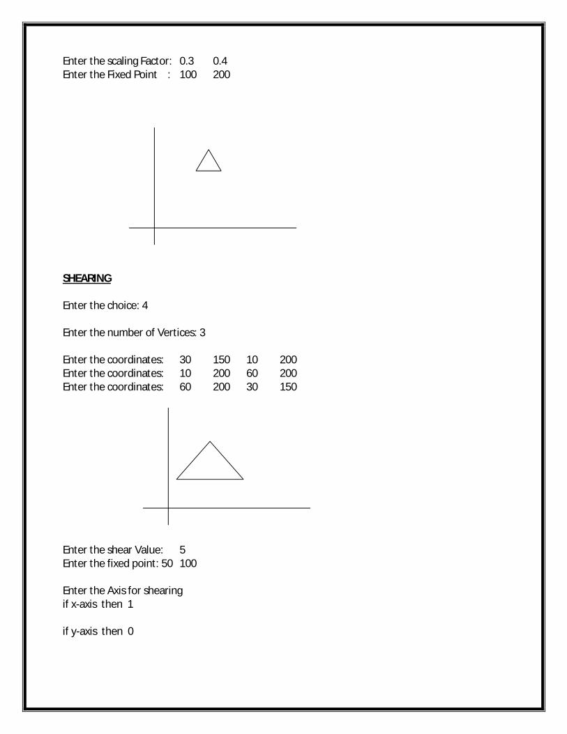
Enter the scaling Factor: 0.3 0.4Enter the Fixed Point : 100 200
SHEARING
Enter the choice: 4
Enter the number of Vertices: 3
Enter the coordinates: 30 150 10 200Enter the coordinates: 10 200 60 200Enter the coordinates: 60 200 30 150
Enter the shear Value: 5Enter the fixed point: 50 100
Enter the Axis for shearing if x-axis then 1 if y-axis then 0
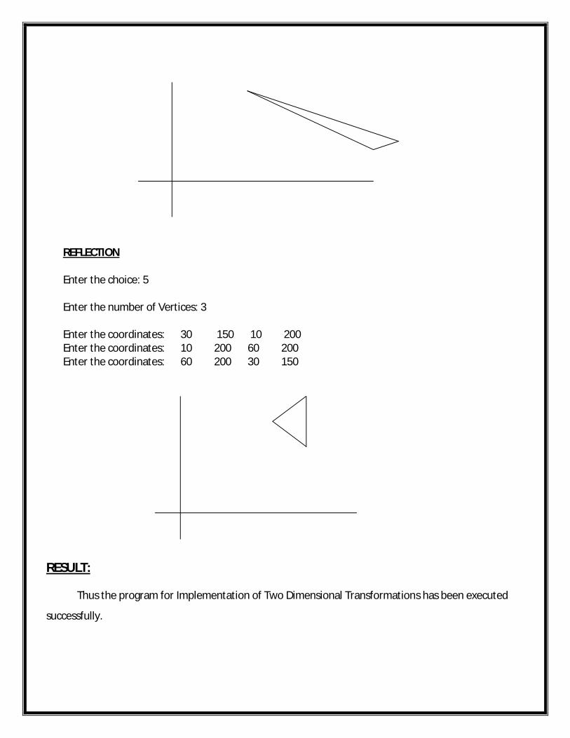
REFLECTION
Enter the choice: 5
Enter the number of Vertices: 3
Enter the coordinates: 30 150 10 200Enter the coordinates: 10 200 60 200Enter the coordinates: 60 200 30 150
RESULT: Thus the program for Implementation of Two Dimensional Transformations has been executed
successfully.
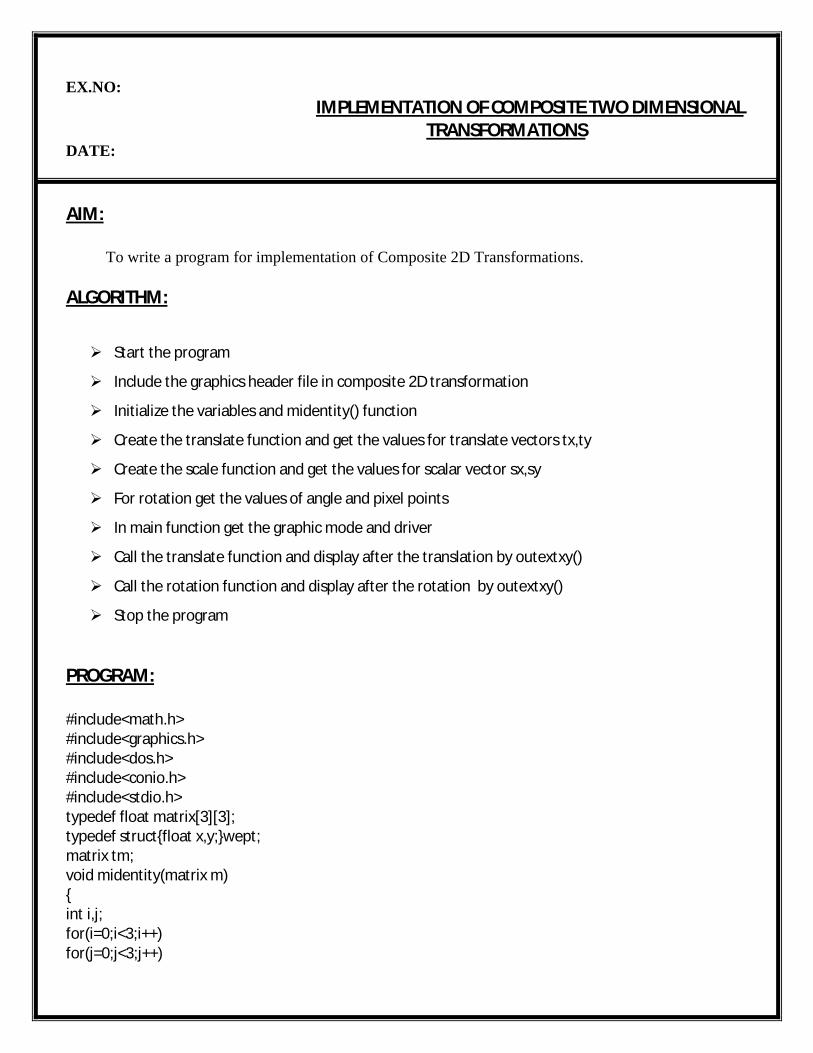
EX.NO:IMPLEMENTATION OF COMPOSITE TWO DIMENSIONAL
TRANSFORMATIONSDATE:
AIM:
To write a program for implementation of Composite 2D Transformations.
ALGORITHM:
Start the program
Include the graphics header file in composite 2D transformation
Initialize the variables and midentity() function
Create the translate function and get the values for translate vectors tx,ty
Create the scale function and get the values for scalar vector sx,sy
For rotation get the values of angle and pixel points
In main function get the graphic mode and driver
Call the translate function and display after the translation by outextxy()
Call the rotation function and display after the rotation by outextxy()
Stop the program
PROGRAM:
#include<math.h>#include<graphics.h>#include<dos.h>#include<conio.h>#include<stdio.h>typedef float matrix[3][3];typedef struct{float x,y;}wept;matrix tm;void midentity(matrix m){int i,j;for(i=0;i<3;i++)for(j=0;j<3;j++)
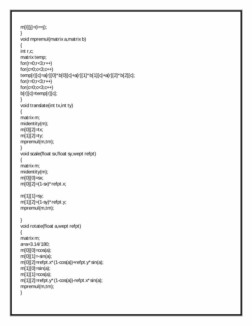
m[i][j]=(i==j);}void mpremul(matrix a,matrix b){int r,c;matrix temp;for(r=0;r<3;r++)for(c=0;c<3;c++)temp[r][c]=a[r][0]*b[0][c]+a[r][1]*b[1][c]+a[r][2]*b[2][c];for(r=0;r<3;r++)for(c=0;c<3;c++)b[r][c]=temp[r][c];}void translate(int tx,int ty){matrix m;midentity(m);m[0][2]=tx;m[1][2]=ty;mpremul(m,tm);}void scale(float sx,float sy,wept refpt){matrix m;midentity(m);m[0][0]=sx;m[0][2]=(1-sx)*refpt.x;
m[1][1]=sy;m[1][2]=(1-sy)*refpt.y;mpremul(m,tm);
}void rotate(float a,wept refpt){matrix m;a=a+3.14/180;m[0][0]=cos(a);m[0][1]=-sin(a);m[0][2]=refpt.x*(1-cos(a))+refpt.y*sin(a);m[1][0]=sin(a);m[1][1]=cos(a);m[1][2]=refpt.y*(1-cos(a))-refpt.x*sin(a);mpremul(m,tm);}
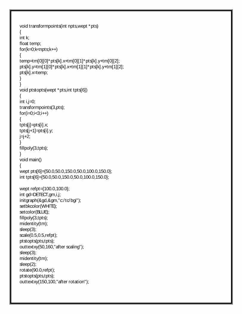
void transformpoints(int npts,wept *pts){int k;float temp;for(k=0;k<npts;k++){temp=tm[0][0]*pts[k].x+tm[0][1]*pts[k].y+tm[0][2];pts[k].y=tm[1][0]*pts[k].x+tm[1][1]*pts[k].y+tm[1][2];pts[k].x=temp;}}void ptstopts(wept *pts,int tpts[6]){int i,j=0;transformpoints(3,pts);for(i=0;i<3;i++){tpts[j]=pts[i].x;tpts[j+1]=pts[i].y;j=j+2;}fillpoly(3,tpts);}void main(){wept pts[6]={50.0,50.0,150.0,50.0,100.0,150.0};int tpts[6]={50.0,50.0,150.0,50.0,100.0,150.0};
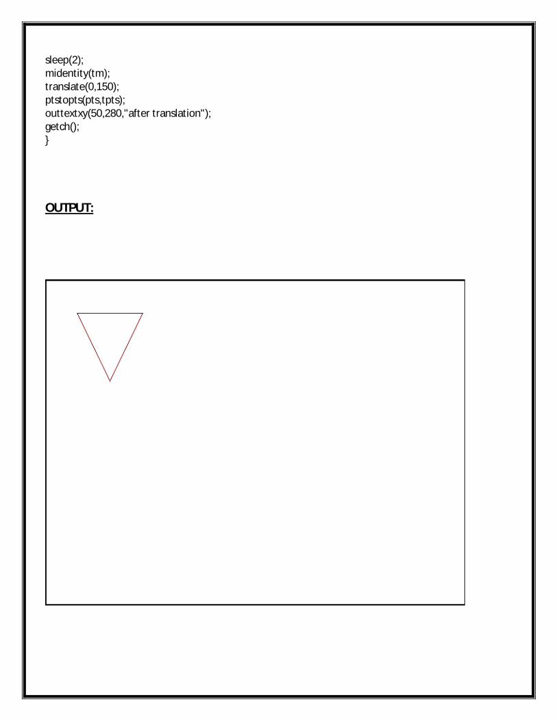
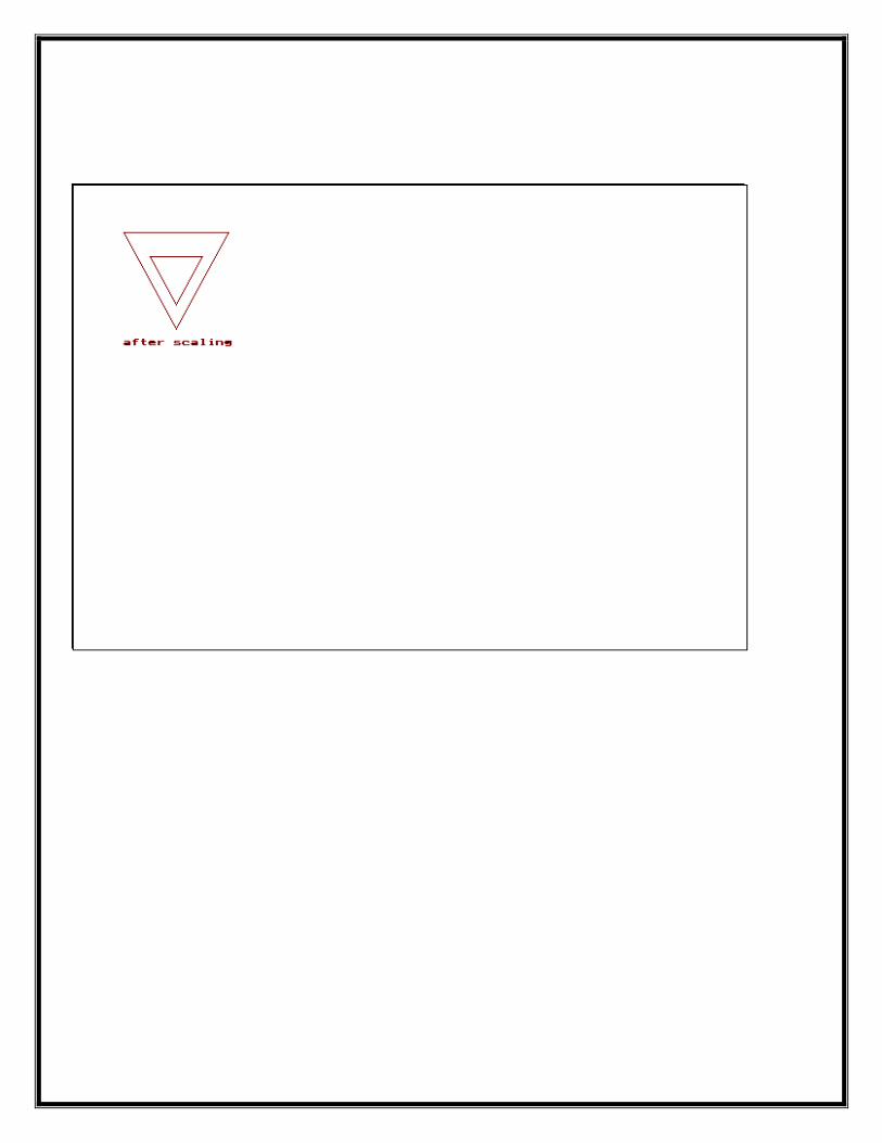
wept refpt={100.0,100.0};int gd=DETECT,gm,i,j;initgraph(&gd,&gm,"c:/tc/bgi");setbkcolor(WHITE);setcolor(BLUE);fillpoly(3,tpts);midentity(tm);sleep(3);scale(0.5,0.5,refpt);ptstopts(pts,tpts);outtextxy(50,160,"after scaling");sleep(3);midentity(tm);sleep(2);rotate(90.0,refpt);ptstopts(pts,tpts);outtextxy(150,100,"after rotation");
sleep(2);midentity(tm);translate(0,150);ptstopts(pts,tpts);outtextxy(50,280,"after translation");getch();}
OUTPUT:
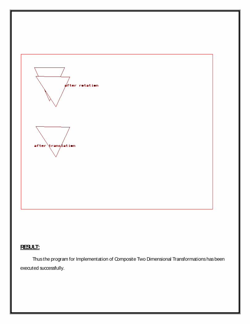
RESULT: Thus the program for Implementation of Composite Two Dimensional Transformations has been
executed successfully.
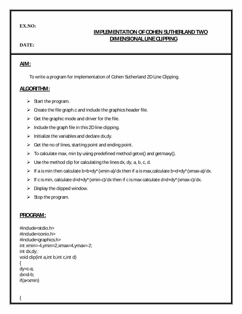
EX.NO:IMPLEMENTATION OF COHEN SUTHERLAND TWO
DIMENSIONAL LINE CLIPPINGDATE:
AIM:
To write a program for implementation of Cohen Sutherland 2D Line Clipping.
ALGORITHM:
Start the program.
Create the file graph.c and include the graphics header file.
Get the graphic mode and driver for the file.
Include the graph file in this 2D line clipping.
Initialize the variables and declare dx,dy.
Get the no of lines, starting point and ending point.
To calculate max, min by using predefined method getxx() and getmaxy().
Use the method clip for calculating the lines dx, dy, a, b, c, d.
If a is min then calculate b=b+dy*(xmin-a)/dx then if a is max,calculate b=d+dy*(xmax-a)/dx.
If c is min, calculate d=d+dy*(xmin-c)/dx then if c is max calculate d=d+dy*(xmax-c)/dx.
Display the clipped window.
Stop the program.
PROGRAM:
#include<stdio.h>#include<conio.h>#include<graphics.h>int xmin=-4,ymin=2,xmax=4,ymax=-2;int dx,dy;void clip(int a,int b,int c,int d){dy=c-a;dx=d-b;if(a<xmin)
{
b=b+dy*(xmin-a)/dx;a=xmin;}if(a>xmax){b=b+dy*(xmax-a)/dx;a=xmax;}if(c<xmin){d=d+dx*(xmin-c)/dy;c=xmin;}if(c>xmax){d=d+dx*(xmax-c)/dy;c=xmax;}if(b<ymin){a=a+dx*(ymin-b)/dy;b=ymin;}if(b>ymax){a=a+dx*(xmax-b)/dy;b=ymax;}if(d<ymin){c=c+dx*(ymin-d)/dy;d=ymin;}if(d>ymax){c=c+dx*(ymax-d)/dy;d=ymax;}setcolor(WHITE);line(a,b,c,d);}void main(){int x1[50],y1[5],x2[50],y2[50],x[50],y[50];
int i,n;
int gd=DETECT,gm;initgraph(&gd,&gm,"d:\\tc\\BGI");printf("Enter the number of lines");scanf("%d",&n);for(i=1;i<=n;i++){printf("Enter the starting point");scanf("%d%d",&x1[i],&y1[i]);printf("Enter the ending point");scanf("%d%d",&x2[i],&y2[i]);}xmin=getmaxx()/2+(20*xmin);xmax=getmaxx()/2+(20*xmax);ymin=getmaxy()/2-(20*ymin);ymax=getmaxy()/2-(20*ymax);setcolor(RED);rectangle(xmin,ymax,xmax,ymin);gotoxy(34,20);printf("Original lines");getch();for(i=1;i<=n;i++){x1[i]=getmaxx()/2+(20*x1[i]);x2[i]=getmaxx()/2+(20*x2[i]);y1[i]=getmaxy()/2-(20*y1[i]);y2[i]=getmaxy()/2-(20*y2[i]);setcolor(3);line(x1[i],y1[i],x2[i],y2[i]);getch();}cleardevice();setcolor(WHITE);rectangle(xmin,ymax,xmax,ymin);gotoxy(34,20);printf("Clipped Lines");getch();for(i=1;i<=n;i++){clip(x1[i],y1[i],x2[i],y2[i]);getch();}}
OUTPUT:
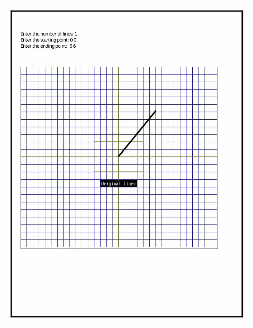
Enter the number of lines: 1Enter the starting point: 0 0Enter the ending point: 6 6
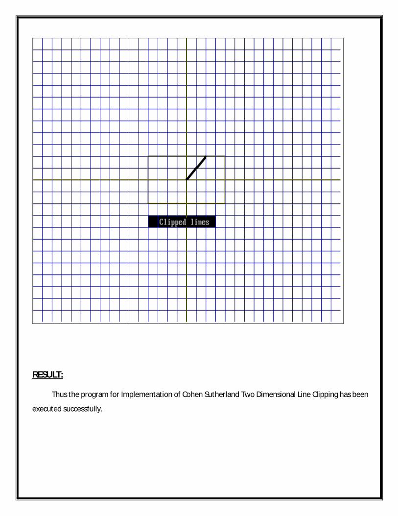
RESULT: Thus the program for Implementation of Cohen Sutherland Two Dimensional Line Clipping has been
executed successfully.
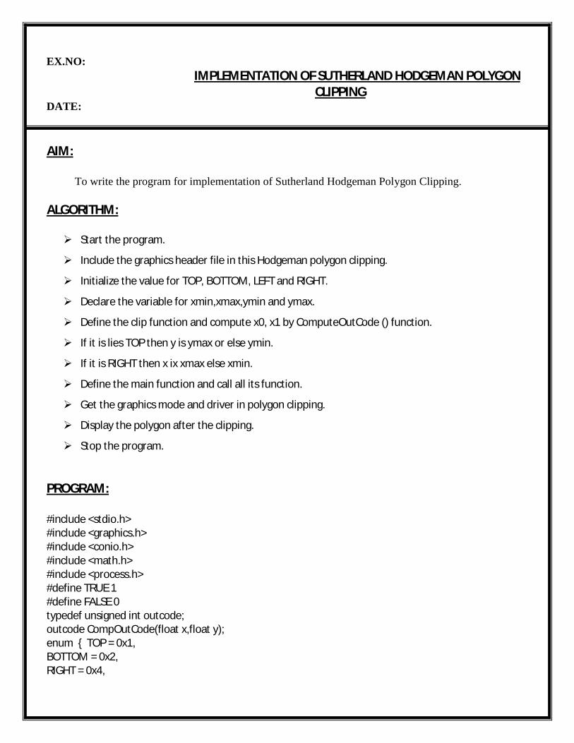
EX.NO:IMPLEMENTATION OF SUTHERLAND HODGEMAN POLYGON
CLIPPINGDATE:
AIM:
To write the program for implementation of Sutherland Hodgeman Polygon Clipping.
ALGORITHM:
Start the program.
Include the graphics header file in this Hodgeman polygon clipping.
Initialize the value for TOP, BOTTOM, LEFT and RIGHT.
Declare the variable for xmin,xmax,ymin and ymax.
Define the clip function and compute x0, x1 by ComputeOutCode () function.
If it is lies TOP then y is ymax or else ymin.
If it is RIGHT then x ix xmax else xmin.
Define the main function and call all its function.
Get the graphics mode and driver in polygon clipping.
Display the polygon after the clipping.
Stop the program.
PROGRAM:
#include <stdio.h>#include <graphics.h>#include <conio.h>#include <math.h>#include <process.h>#define TRUE 1#define FALSE 0typedef unsigned int outcode;outcode CompOutCode(float x,float y);enum { TOP = 0x1,BOTTOM = 0x2,RIGHT = 0x4,
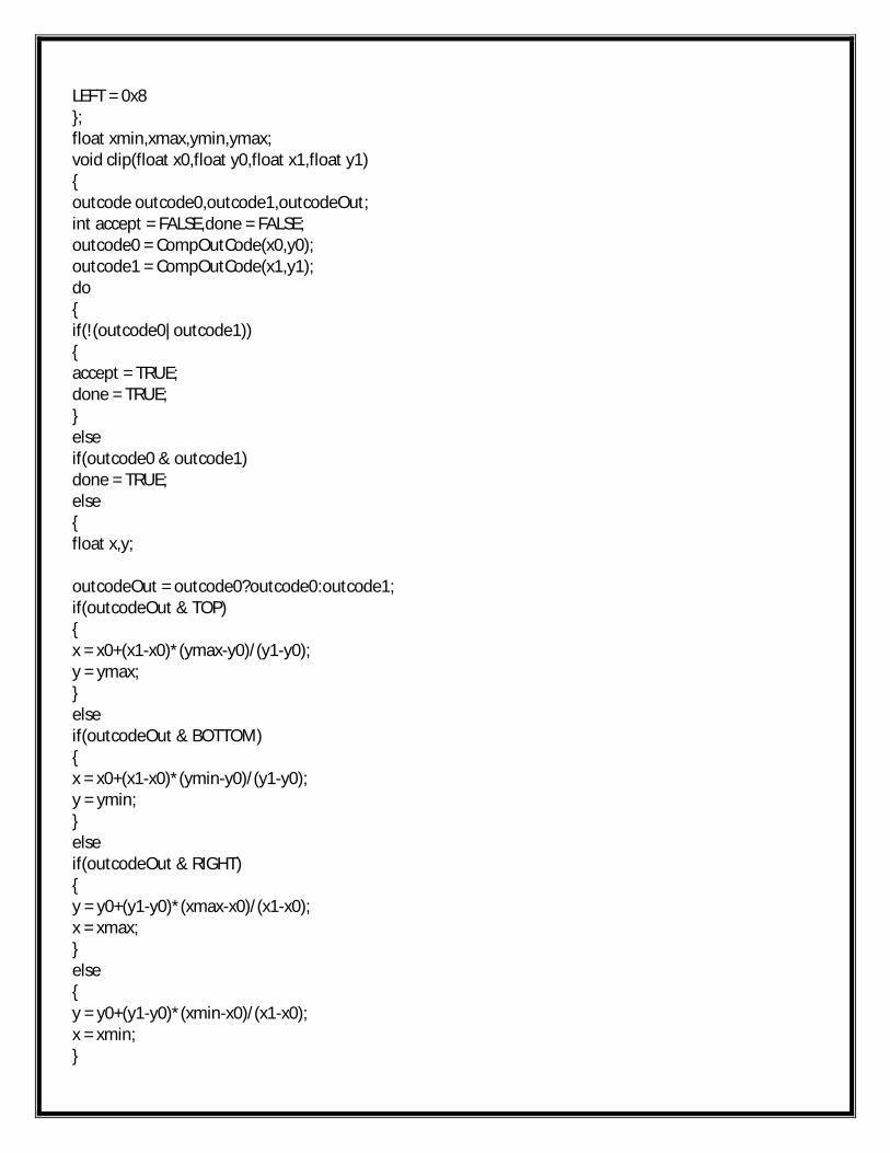
LEFT = 0x8};float xmin,xmax,ymin,ymax;void clip(float x0,float y0,float x1,float y1){outcode outcode0,outcode1,outcodeOut;int accept = FALSE,done = FALSE;outcode0 = CompOutCode(x0,y0);outcode1 = CompOutCode(x1,y1);do{if(!(outcode0|outcode1)){accept = TRUE;done = TRUE;}elseif(outcode0 & outcode1)done = TRUE;else{float x,y;
outcodeOut = outcode0?outcode0:outcode1;if(outcodeOut & TOP){x = x0+(x1-x0)*(ymax-y0)/(y1-y0);y = ymax;}elseif(outcodeOut & BOTTOM){x = x0+(x1-x0)*(ymin-y0)/(y1-y0);y = ymin;}elseif(outcodeOut & RIGHT){y = y0+(y1-y0)*(xmax-x0)/(x1-x0);x = xmax;}else{y = y0+(y1-y0)*(xmin-x0)/(x1-x0);x = xmin;}
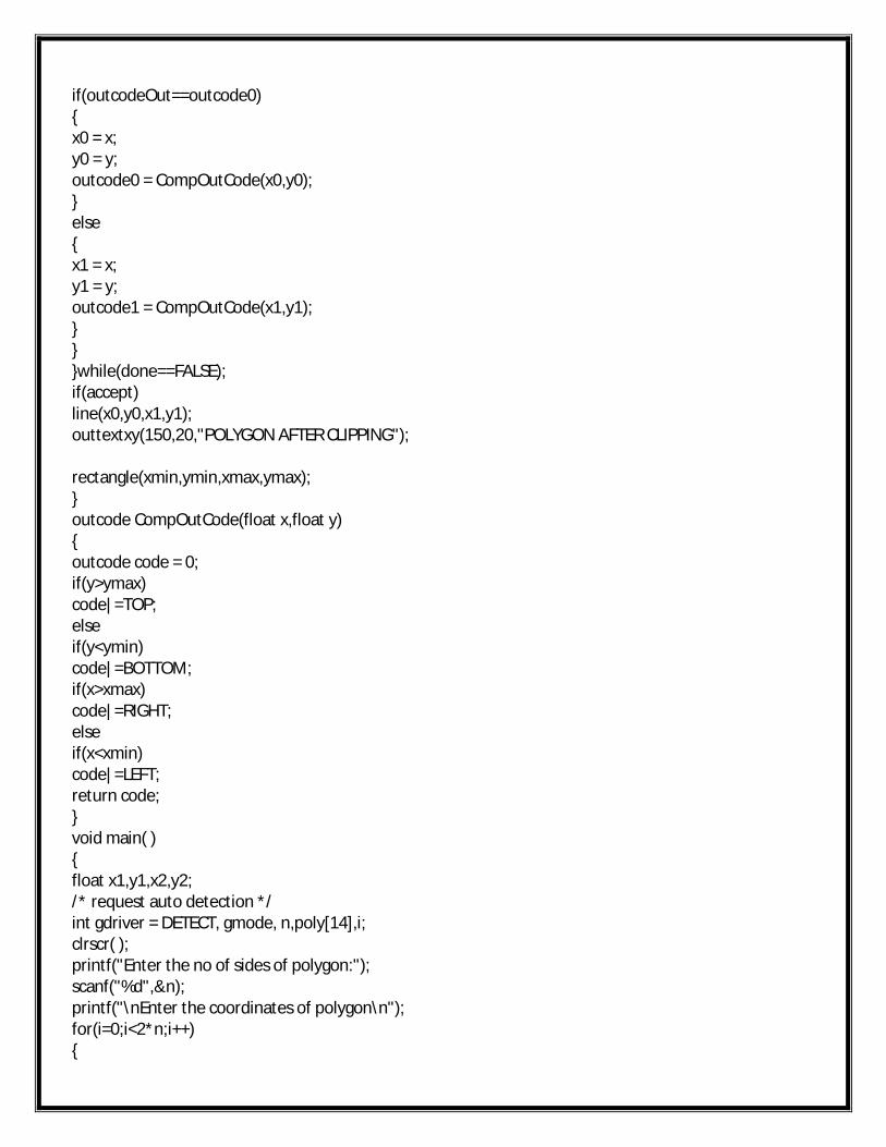
if(outcodeOut==outcode0){x0 = x;y0 = y;outcode0 = CompOutCode(x0,y0);}else{x1 = x;y1 = y;outcode1 = CompOutCode(x1,y1);}}}while(done==FALSE);if(accept)line(x0,y0,x1,y1);outtextxy(150,20,"POLYGON AFTER CLIPPING");
rectangle(xmin,ymin,xmax,ymax);}outcode CompOutCode(float x,float y){outcode code = 0;if(y>ymax)code|=TOP;elseif(y<ymin)code|=BOTTOM;if(x>xmax)code|=RIGHT;elseif(x<xmin)code|=LEFT;return code;}void main( ){float x1,y1,x2,y2;/* request auto detection */int gdriver = DETECT, gmode, n,poly[14],i;clrscr( );printf("Enter the no of sides of polygon:");scanf("%d",&n);printf("\nEnter the coordinates of polygon\n");for(i=0;i<2*n;i++){
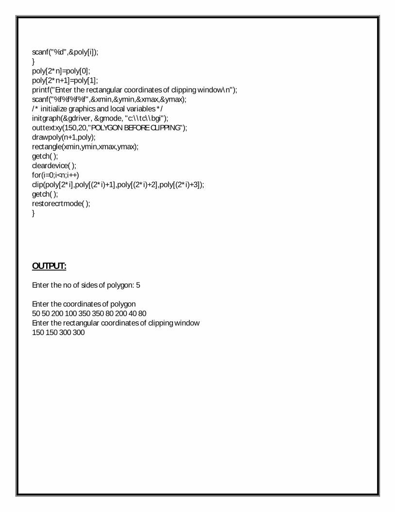
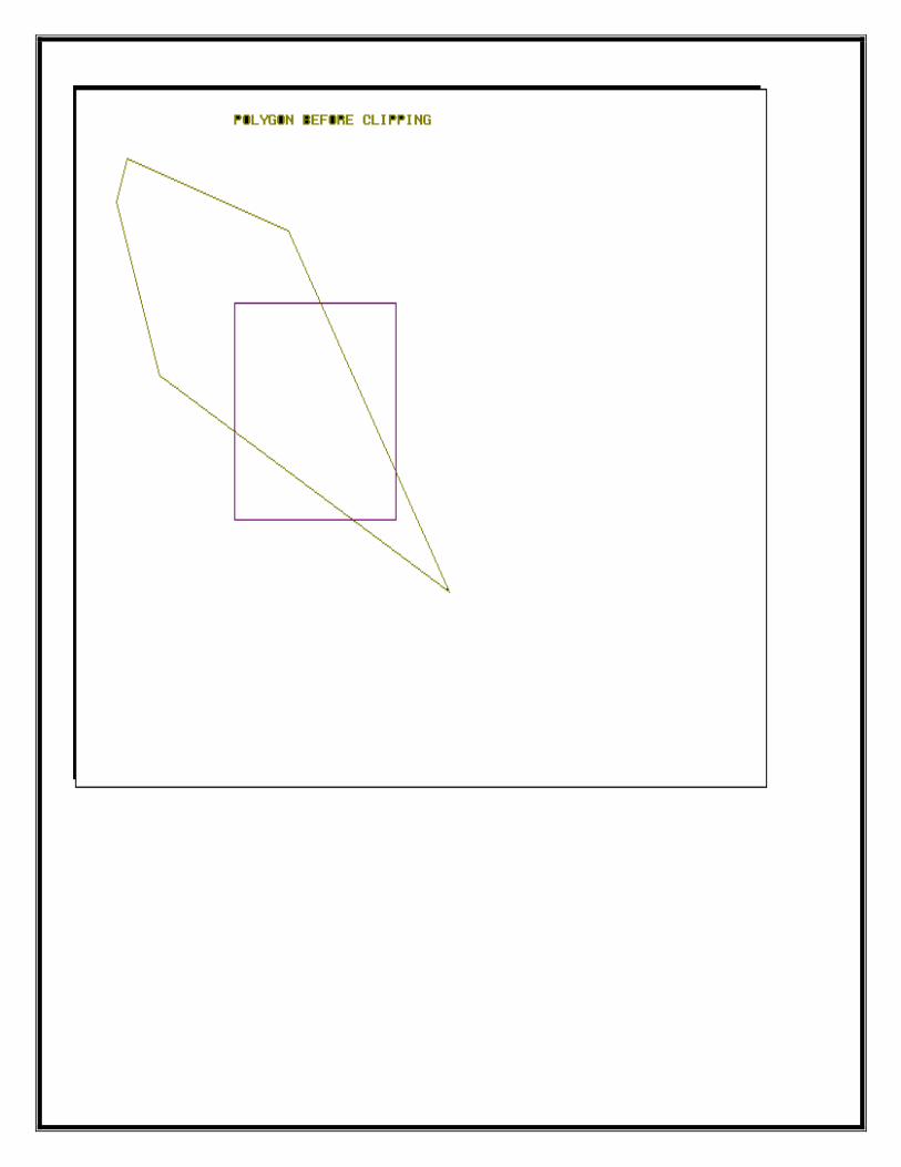
scanf("%d",&poly[i]);}poly[2*n]=poly[0];poly[2*n+1]=poly[1];printf("Enter the rectangular coordinates of clipping window\n");scanf("%f%f%f%f",&xmin,&ymin,&xmax,&ymax);/* initialize graphics and local variables */initgraph(&gdriver, &gmode, "c:\\tc\\bgi");outtextxy(150,20,"POLYGON BEFORE CLIPPING");drawpoly(n+1,poly);rectangle(xmin,ymin,xmax,ymax);getch( );cleardevice( );for(i=0;i<n;i++)clip(poly[2*i],poly[(2*i)+1],poly[(2*i)+2],poly[(2*i)+3]);getch( );restorecrtmode( );}
OUTPUT:
Enter the no of sides of polygon: 5
Enter the coordinates of polygon50 50 200 100 350 350 80 200 40 80Enter the rectangular coordinates of clipping window150 150 300 300
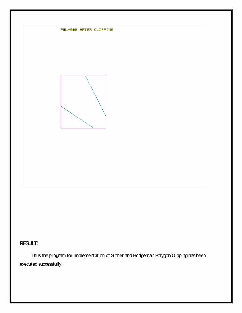
RESULT: Thus the program for Implementation of Sutherland Hodgeman Polygon Clipping has been
executed successfully.
EX.NO:IMPLEMENTATION OF THREE DIMENSIONAL
TRANSFORMATIONSDATE:
AIM:
To write the program for implementation of three dimensional transformations.
ALGORITHM:
Start the program.
Initialize the variables maxx,maxy,midx,midy.
Assign the variables gd,gm,x,y,z,o,x1,x2,y1,y2 in main method.
Assign getmaxx() to maxx variable and getmaxy() to maxy variable.
The method bar3d () is initialized.
Enter the Translation, Scaling & Rotation factor in printf() method.
Calculate x1, x2, y1, y2 and display results in respective co-ordinates.
Display the results after performing Translation, Rotation &Scaling.
Stop the program.
PROGRAM:
#include<stdio.h>#include<conio.h>#include<graphics.h>#include<math.h>int maxx,maxy,midx,midy;void axis(){getch();cleardevice();line(midx,0,midx,maxy);line(0,midy,maxx,midy);}void main(){int gd,gm,x,y,z,o,x1,x2,y1,y2;
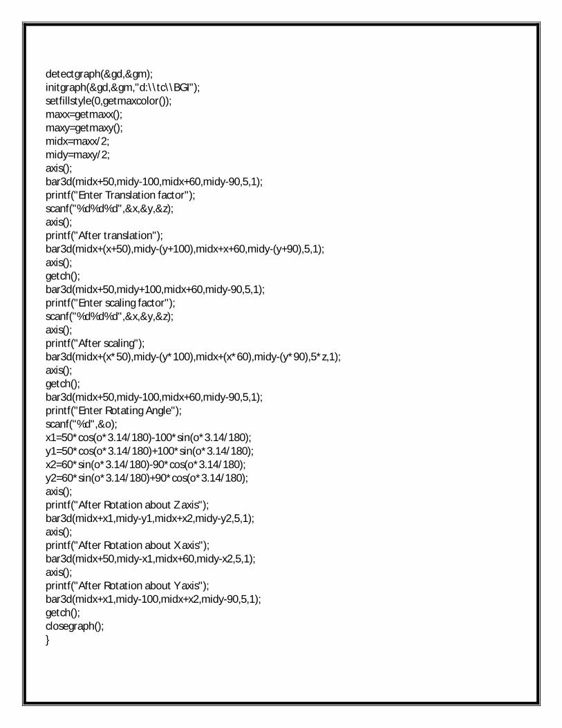
detectgraph(&gd,&gm);initgraph(&gd,&gm,"d:\\tc\\BGI");setfillstyle(0,getmaxcolor());maxx=getmaxx();maxy=getmaxy();midx=maxx/2;midy=maxy/2;axis();bar3d(midx+50,midy-100,midx+60,midy-90,5,1);printf("Enter Translation factor");scanf("%d%d%d",&x,&y,&z);axis();printf("After translation");bar3d(midx+(x+50),midy-(y+100),midx+x+60,midy-(y+90),5,1);axis();getch();bar3d(midx+50,midy+100,midx+60,midy-90,5,1);printf("Enter scaling factor");scanf("%d%d%d",&x,&y,&z);axis();printf("After scaling");bar3d(midx+(x*50),midy-(y*100),midx+(x*60),midy-(y*90),5*z,1);axis();getch();bar3d(midx+50,midy-100,midx+60,midy-90,5,1);printf("Enter Rotating Angle");scanf("%d",&o);x1=50*cos(o*3.14/180)-100*sin(o*3.14/180);y1=50*cos(o*3.14/180)+100*sin(o*3.14/180);x2=60*sin(o*3.14/180)-90*cos(o*3.14/180);y2=60*sin(o*3.14/180)+90*cos(o*3.14/180);axis();printf("After Rotation about Z axis");bar3d(midx+x1,midy-y1,midx+x2,midy-y2,5,1);axis();printf("After Rotation about X axis");bar3d(midx+50,midy-x1,midx+60,midy-x2,5,1);axis();printf("After Rotation about Y axis");bar3d(midx+x1,midy-100,midx+x2,midy-90,5,1);getch();closegraph();}
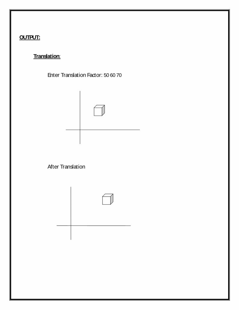
OUTPUT:
Translation:
Enter Translation Factor: 50 60 70
After Translation
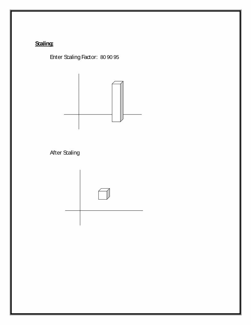
Scaling:
Enter Scaling Factor: 80 90 95
After Scaling
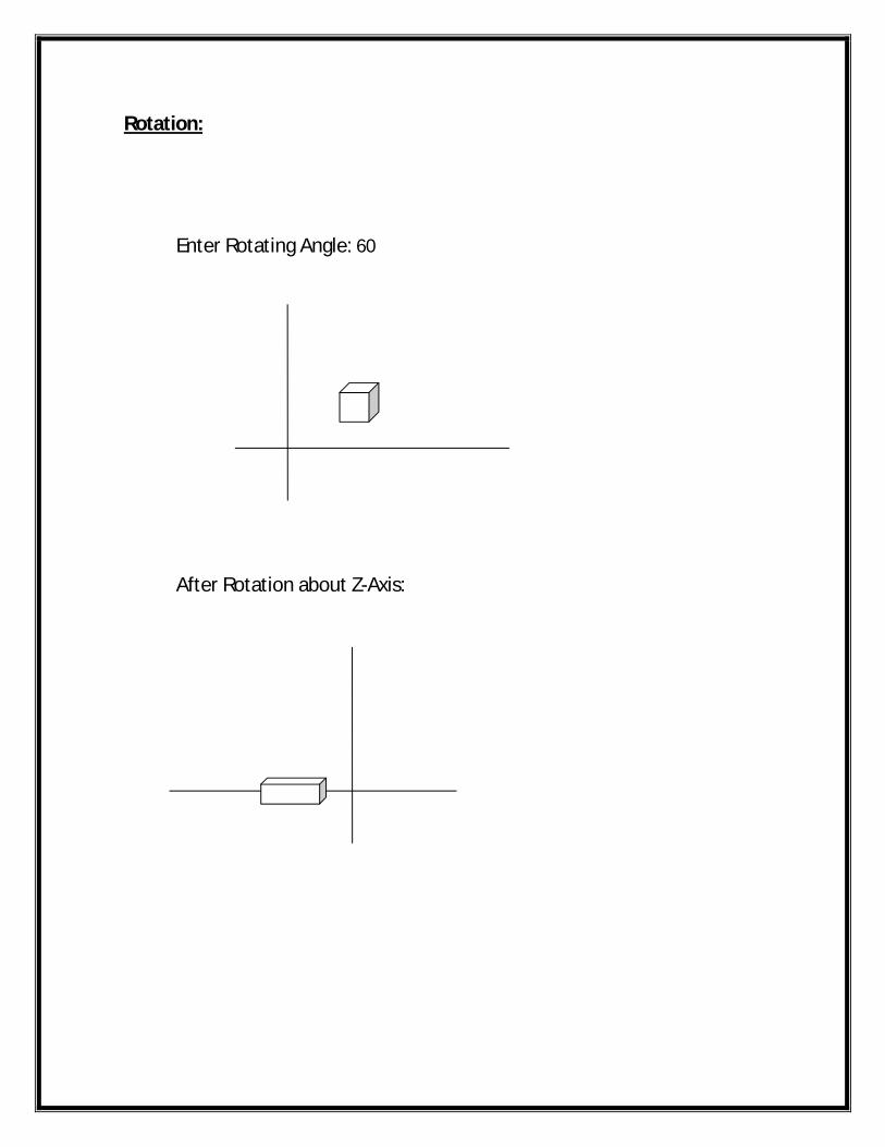
Rotation:
Enter Rotating Angle: 60
After Rotation about Z-Axis:
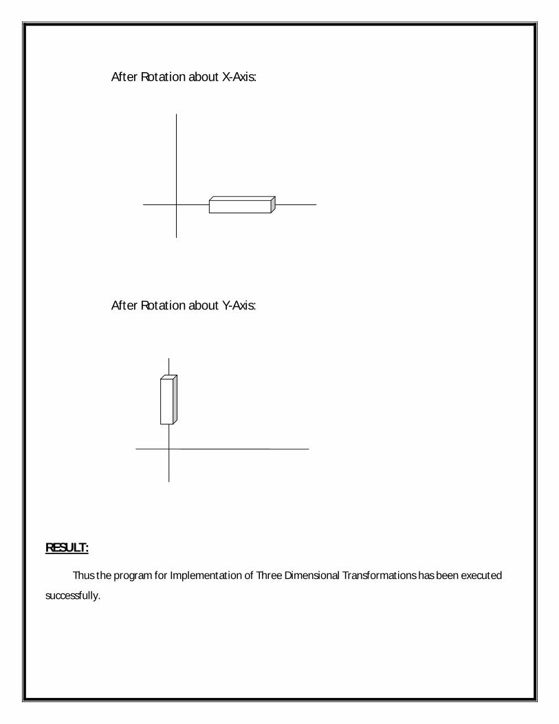
After Rotation about X-Axis:
After Rotation about Y-Axis:
RESULT: Thus the program for Implementation of Three Dimensional Transformations has been executed
successfully.
EX.NO:IMPLEMENTATION OF COMPOSITE THREE DIMENSIONAL
TRANSFORMATIONSDATE:
AIM:
To write a program for implementation of composite three dimensional transformations.
ALGORITHM:
Start the program
Define all necessary headers for three dimensional transformations.
Declare the variables i,j,k,temp in MultiMatrix() method.
Using malloc the memory can be allocated for column size.
Using for loop to instantiate row and column.
In ResetMatrix () method the matrix are represented in three dimensional form.
The methods movto2 (), lineto2 (), outtextxy (), Draw (), Rotate (), Move () are defined.
Initialize the graphic interface.
In switch statement the values are checked in each case.
Display the output in composite three dimensional transformations.
Stop the program.
PROGRAM:
#include<process.h>#include <stdio.h>#include <graphics.h>#include<conio.h>#include <stdlib.h>#include <math.h>#define ROTATE_X 0#define ROTATE_Y 1#define ROTATE_Z 2#define R_STEP 2.0double CAMERA_D =800;double CAMERA_Z =1000;
#define KEY_PAGEUP 73#define KEY_PAGEDOWN 81#define KEY_UP 72#define KEY_DOWN 80#define KEY_LEFT 75#define KEY_RIGHT 77#define KEY_ESC 27double house[28][4]={0,0,0,1,0,0,0,1,-20,0,100,1,20,0,100,1,20,-100,-100,1,-20,-100,-100,1,-20,100,-100,1,20,100,-100,1,0,0,0, 1,0,0,0,1,0,0,0,1,0,0,0,1,0,0,0,1,0,0,0,1,0,0,0,1,0,0,0,1,
20,0,-100,1,-20,0,-100,1,0,0,0,1,0,0,0,1,
20,-100,100,1,-20,-100,100,1,-20,100,100,1,20,100,100,1,
0, 0, 0, 1, /* center row=24 */100, 0, 0, 1, /* x axis */0, 100, 0, 1, /* y axis */0, 0, 100, 1, /* z axis */};
void MultiMatrix(double mat1[],double mat2[][4],int row,int col){int i,j,k;double *temp;temp=(double*)malloc(col*sizeof(double));for(i=0;i<row;i++){for(j=0;j<col;j++)
{temp[j]=0;for(k=0;k<col;k++)temp[j]=temp[j]+mat1[i*col+k]*mat2[k][j];}for(j=0;j<col;j++)
mat1[i*col+j]=temp[j];}free(temp);
}void ResetMatrix(double Matrix[4][4]){
Matrix[0][0]=1.0; Matrix[0][1]=0.0; Matrix[0][2]=0.0; Matrix[0][3]=0.0;Matrix[1][0]=0.0; Matrix[1][1]=1.0; Matrix[1][2]=0.0; Matrix[1][3]=0.0;Matrix[2][0]=0.0; Matrix[2][1]=0.0; Matrix[2][2]=1.0; Matrix[2][3]=0.0;Matrix[3][0]=0.0; Matrix[3][1]=0.0; Matrix[3][2]=0.0; Matrix[3][3]=1.0;}void lineto2(double x,double y,double z){z+=CAMERA_Z; if (z<0.000001) z=0.000001;x=(double)CAMERA_D*x/z;y=(double)CAMERA_D*y/z; lineto(320+(int)x,240-(int)y);}void moveto2(double x,double y,double z){z+=CAMERA_Z;if (z<0.000001) z=0.000001;x=(double)CAMERA_D*x/z;y=(double)CAMERA_D*y/z;moveto(320+(int)x,240-(int)y);}void outtextxy2(double x,double y,double z,char *str){z+=CAMERA_Z;if (z<0.000001) z=0.000001;x=(double)CAMERA_D*x/z;y=(double)CAMERA_D*y/z;outtextxy(320+(int)x,240-(int)y,str);}void Draw(double house[28][4],int Color,int DispAxis){double x0,y0,z0,x1,y1,z1,x2,y2,z2,x3,y3,z3;int nface=0;setcolor(Color);setlinestyle(SOLID_LINE,0,3);for(nface=0;nface<6;nface++){moveto2(house[nface*4][0],house[nface*4][1],house[nface*4][2]);lineto2(house[nface*4+1][0],house[nface*4+1][1],house[nface*4+1][2]);lineto2(house[nface*4+2][0],house[nface*4+2][1],house[nface*4+2][2]);lineto2(house[nface*4+3][0],house[nface*4+3][1],house[nface*4+3][2]);lineto2(house[nface*4][0],house[nface*4][1],house[nface*4][2]);}if(DispAxis){
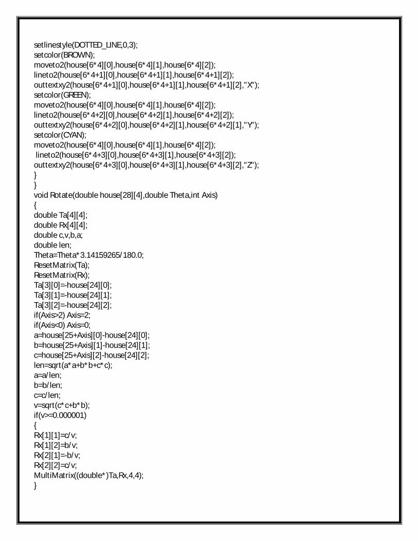
setlinestyle(DOTTED_LINE,0,3);setcolor(BROWN);moveto2(house[6*4][0],house[6*4][1],house[6*4][2]);lineto2(house[6*4+1][0],house[6*4+1][1],house[6*4+1][2]);outtextxy2(house[6*4+1][0],house[6*4+1][1],house[6*4+1][2],"X");setcolor(GREEN);moveto2(house[6*4][0],house[6*4][1],house[6*4][2]);lineto2(house[6*4+2][0],house[6*4+2][1],house[6*4+2][2]);outtextxy2(house[6*4+2][0],house[6*4+2][1],house[6*4+2][1],"Y");setcolor(CYAN);moveto2(house[6*4][0],house[6*4][1],house[6*4][2]);lineto2(house[6*4+3][0],house[6*4+3][1],house[6*4+3][2]);
outtextxy2(house[6*4+3][0],house[6*4+3][1],house[6*4+3][2],"Z");}}void Rotate(double house[28][4],double Theta,int Axis){double Ta[4][4];double Rx[4][4];double c,v,b,a;double len;Theta=Theta*3.14159265/180.0;ResetMatrix(Ta);ResetMatrix(Rx);Ta[3][0]=-house[24][0];Ta[3][1]=-house[24][1];Ta[3][2]=-house[24][2];if(Axis>2) Axis=2;if(Axis<0) Axis=0; a=house[25+Axis][0]-house[24][0];b=house[25+Axis][1]-house[24][1];c=house[25+Axis][2]-house[24][2];len=sqrt(a*a+b*b+c*c);a=a/len;b=b/len;c=c/len;v=sqrt(c*c+b*b);if(v>=0.000001){Rx[1][1]=c/v;Rx[1][2]=b/v;Rx[2][1]=-b/v;Rx[2][2]=c/v;MultiMatrix((double*)Ta,Rx,4,4);}
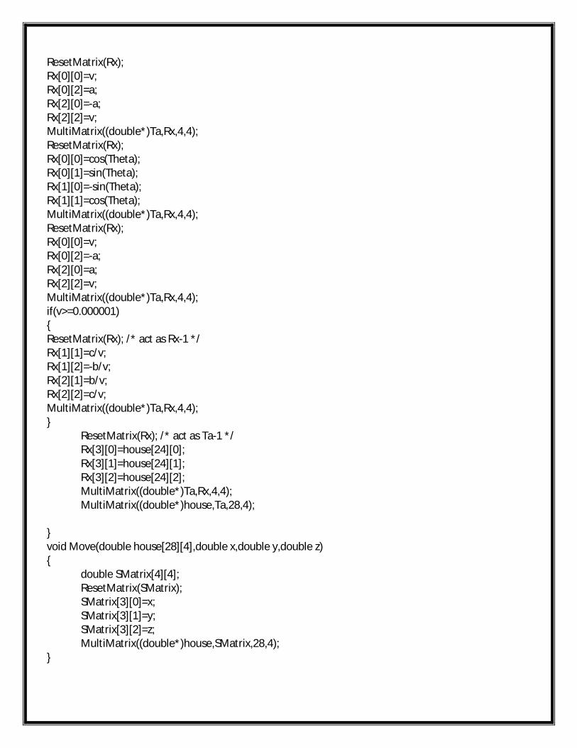
ResetMatrix(Rx); Rx[0][0]=v;Rx[0][2]=a;Rx[2][0]=-a;Rx[2][2]=v;MultiMatrix((double*)Ta,Rx,4,4);ResetMatrix(Rx); Rx[0][0]=cos(Theta);Rx[0][1]=sin(Theta);Rx[1][0]=-sin(Theta);Rx[1][1]=cos(Theta);MultiMatrix((double*)Ta,Rx,4,4);ResetMatrix(Rx); Rx[0][0]=v;Rx[0][2]=-a;Rx[2][0]=a;Rx[2][2]=v;MultiMatrix((double*)Ta,Rx,4,4);if(v>=0.000001){ResetMatrix(Rx); /* act as Rx-1 */Rx[1][1]=c/v;Rx[1][2]=-b/v;Rx[2][1]=b/v;Rx[2][2]=c/v;MultiMatrix((double*)Ta,Rx,4,4);}
ResetMatrix(Rx); /* act as Ta-1 */Rx[3][0]=house[24][0];Rx[3][1]=house[24][1];Rx[3][2]=house[24][2];MultiMatrix((double*)Ta,Rx,4,4);MultiMatrix((double*)house,Ta,28,4);
}void Move(double house[28][4],double x,double y,double z){
double SMatrix[4][4];ResetMatrix(SMatrix);SMatrix[3][0]=x;SMatrix[3][1]=y;SMatrix[3][2]=z;MultiMatrix((double*)house,SMatrix,28,4);
}
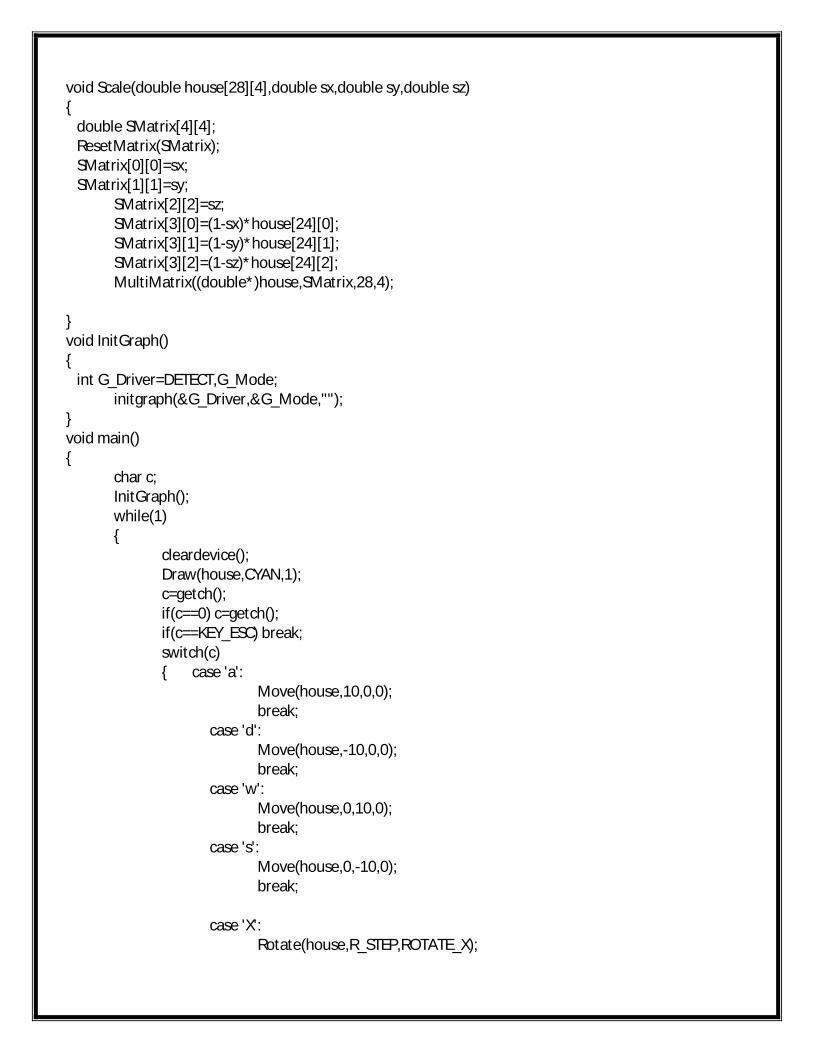
void Scale(double house[28][4],double sx,double sy,double sz){ double SMatrix[4][4]; ResetMatrix(SMatrix); SMatrix[0][0]=sx; SMatrix[1][1]=sy;
SMatrix[2][2]=sz;SMatrix[3][0]=(1-sx)*house[24][0];SMatrix[3][1]=(1-sy)*house[24][1];SMatrix[3][2]=(1-sz)*house[24][2];MultiMatrix((double*)house,SMatrix,28,4);
}void InitGraph(){ int G_Driver=DETECT,G_Mode;
initgraph(&G_Driver,&G_Mode,"");}void main(){
char c;InitGraph();while(1){
cleardevice();Draw(house,CYAN,1);c=getch();if(c==0) c=getch();if(c==KEY_ESC) break;switch(c){ case 'a':
Move(house,10,0,0);break;
case 'd':Move(house,-10,0,0);break;
case 'w':Move(house,0,10,0);break;
case 's':Move(house,0,-10,0);break;
case 'X':Rotate(house,R_STEP,ROTATE_X);
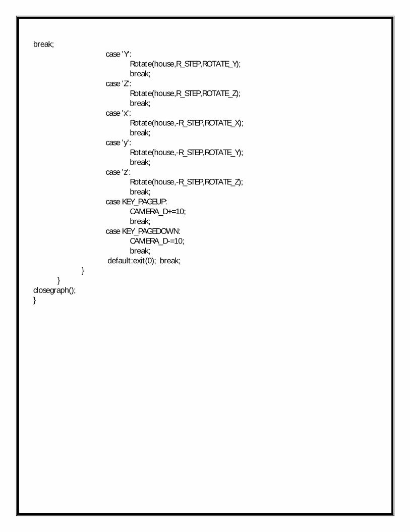
break;case 'Y':
Rotate(house,R_STEP,ROTATE_Y);break;
case 'Z':Rotate(house,R_STEP,ROTATE_Z);break;
case 'x':Rotate(house,-R_STEP,ROTATE_X);break;
case 'y':Rotate(house,-R_STEP,ROTATE_Y);break;
case 'z':Rotate(house,-R_STEP,ROTATE_Z);break;
case KEY_PAGEUP:CAMERA_D+=10;break;
case KEY_PAGEDOWN:CAMERA_D-=10;break;
default:exit(0); break;}
}closegraph();}
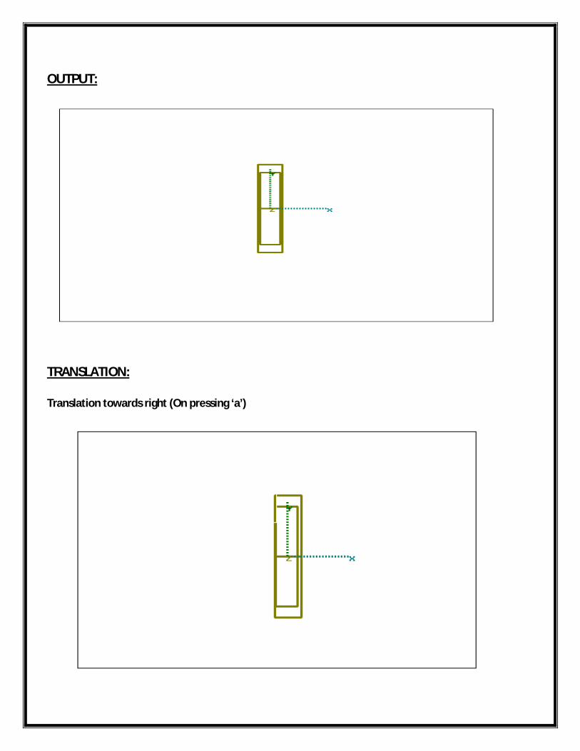
OUTPUT:
TRANSLATION:
Translation towards right (On pressing ‘a’)
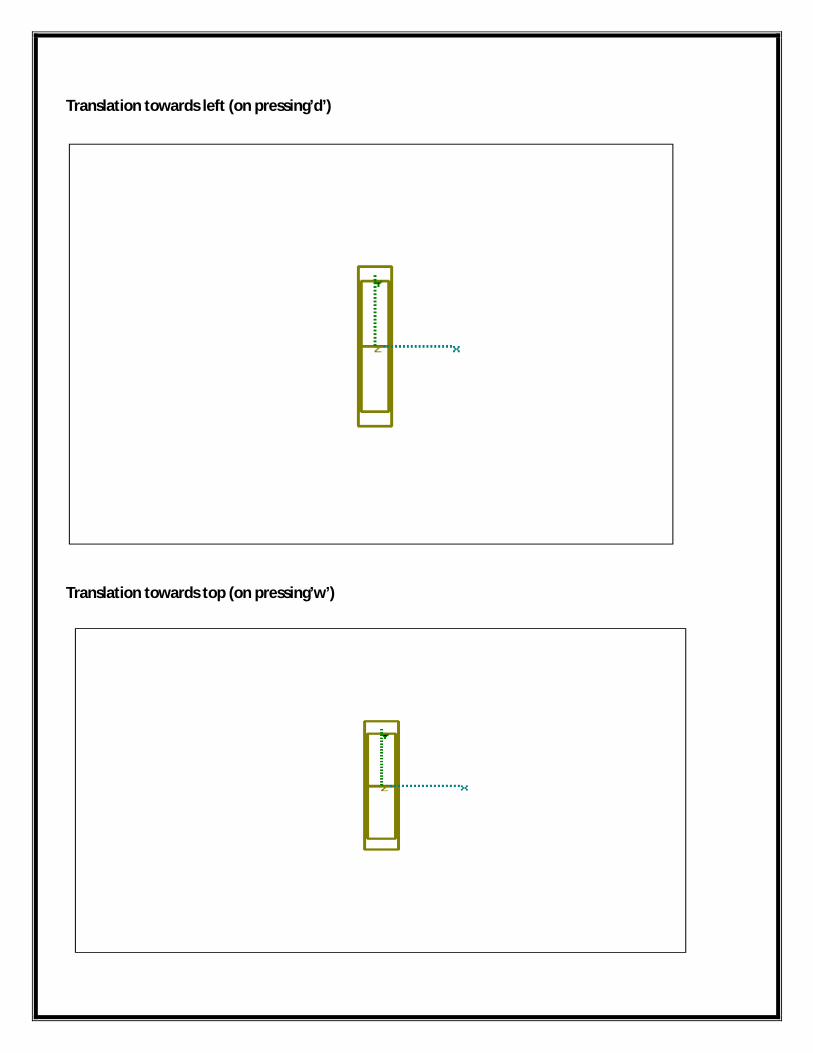
Translation towards left (on pressing’d’)
Translation towards top (on pressing’w’)
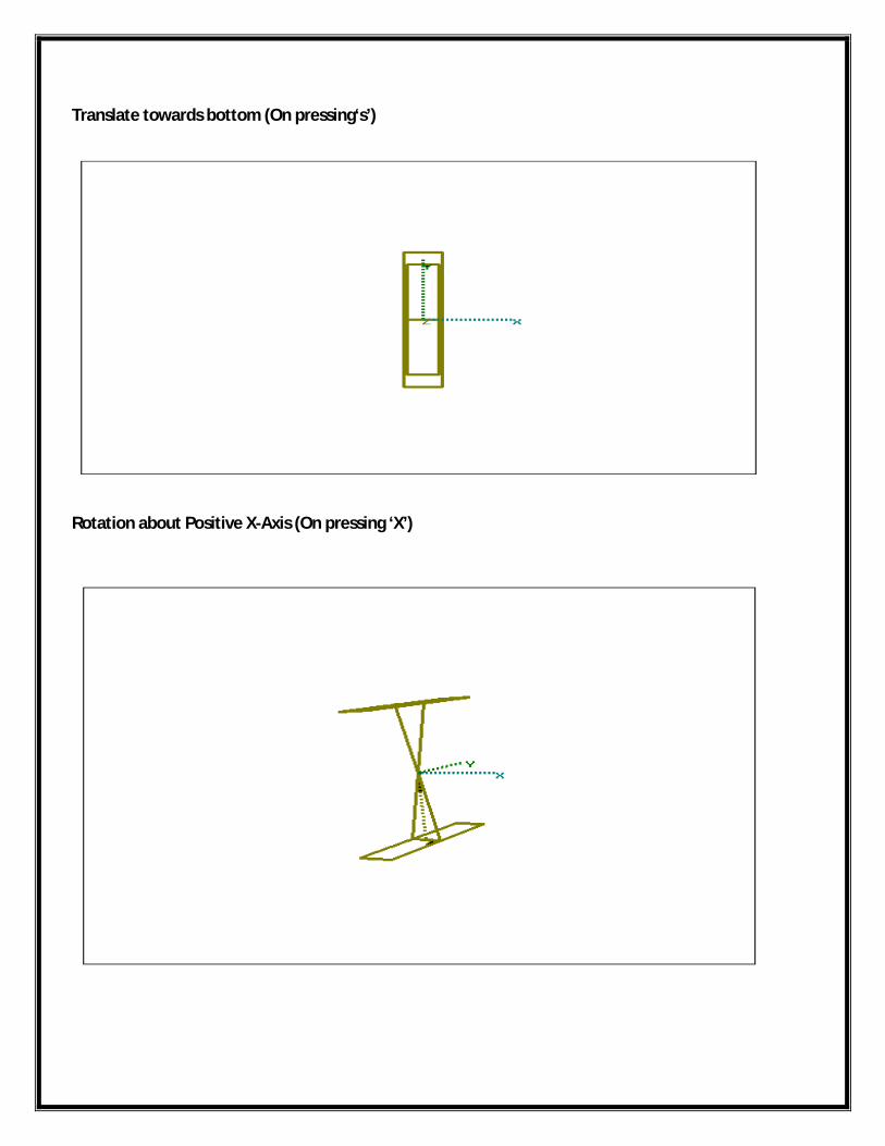
Translate towards bottom (On pressing‘s’)
Rotation about Positive X-Axis (On pressing ‘X’)
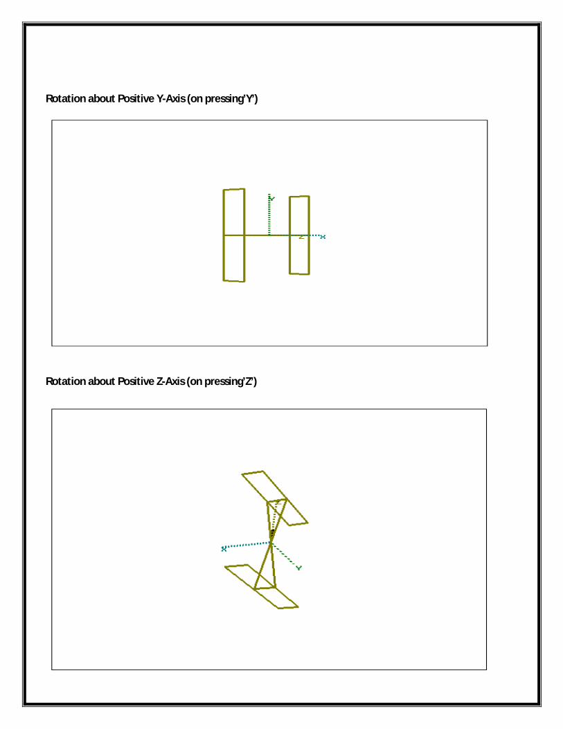
Rotation about Positive Y-Axis (on pressing’Y’)
Rotation about Positive Z-Axis (on pressing’Z’)
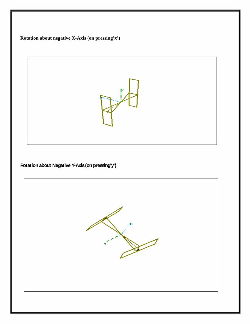
Rotation about negative X-Axis (on pressing’x’)
Rotation about Negative Y-Axis (on pressing’y’)
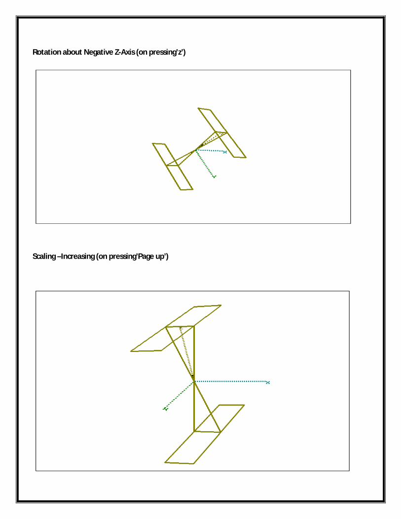
Rotation about Negative Z-Axis (on pressing’z’)
Scaling –Increasing (on pressing’Page up’)
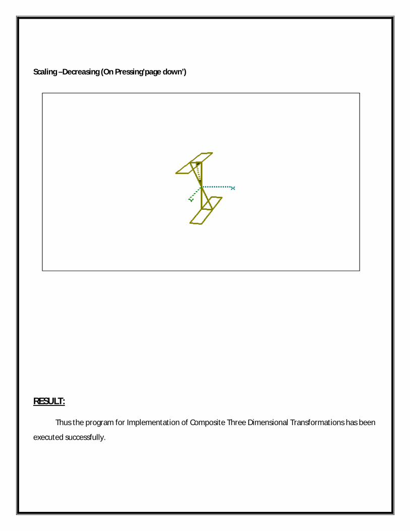
Scaling –Decreasing (On Pressing’page down’)
RESULT: Thus the program for Implementation of Composite Three Dimensional Transformations has been
executed successfully.

EX.NO:DRAWING THREE DIMENSIONAL OBJECTS
DATE:
AIM:
To write a program for drawing three dimensional objects.
ALGORITHM: Start the program.
Initialize the graphics interface.
Assign values to rectangle () & lines ().
Using the methods setcolor () & setfillstyle () to fill colors in bar chart.
Assign values to bar3d () method to draw bar chart.
The methods settextstyle () & setlinestyle () are used to represent line style and text style.
Display the bar chart in 3d view.
Stop the program.
PROGRAM:
#include<graphics.h>#include<conio.h>int main(){int gd=DETECT,gm;initgraph(&gd,&gm,"d:\\tc\\BGI");setcolor(YELLOW);rectangle(0,30,639,450);settextstyle(SANS_SERIF_FONT,HORIZ_DIR,2);setcolor(WHITE);outtextxy(275,0,"Bar Chart");setlinestyle(SOLID_LINE,0,2);line(100,420,100,60);line(100,420,600,420);line(90,70,100,60);line(110,70,100,60);line(590,410,600,420);line(590,430,600,420);

outtextxy(95,35,"Y");outtextxy(610,405,"X");outtextxy(85,415,"O");setfillstyle(LINE_FILL,BLUE);bar3d(150,100,200,419,12,1);setfillstyle(XHATCH_FILL,RED);bar3d(225,150,275,419,12,1);setfillstyle(WIDE_DOT_FILL,GREEN);bar3d(300,200,350,419,12,1);setfillstyle(INTERLEAVE_FILL,MAGENTA);bar3d(375,125,425,419,12,1);setfillstyle(HATCH_FILL,BROWN);bar3d(450,175,500,419,12,1);getch();return(0);}
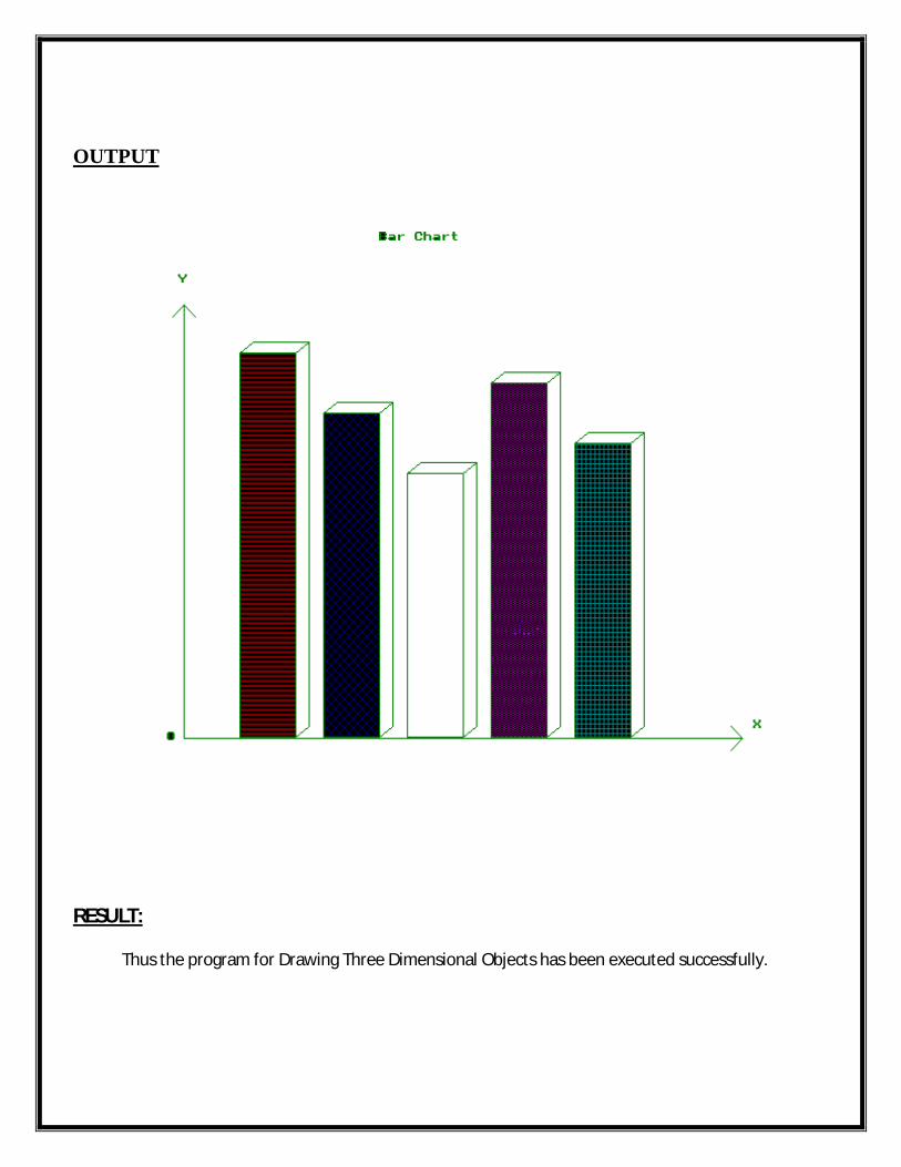
OUTPUT
RESULT: Thus the program for Drawing Three Dimensional Objects has been executed successfully.
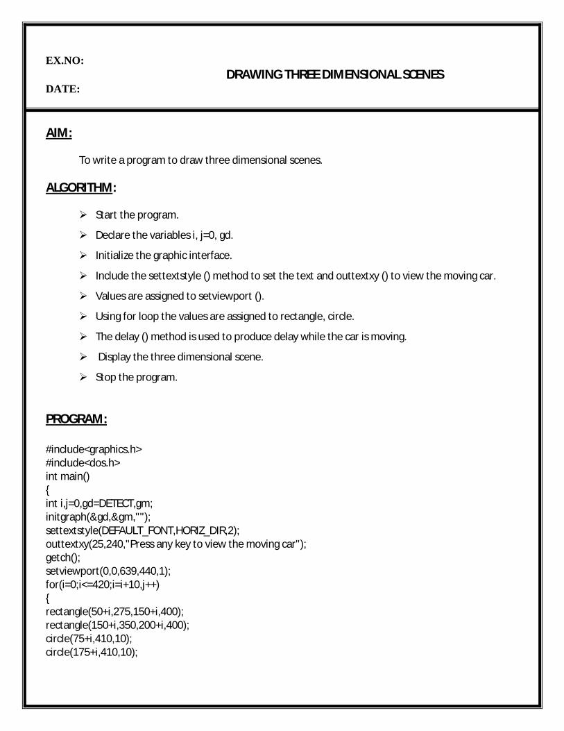
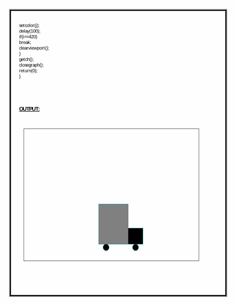
EX.NO:DRAWING THREE DIMENSIONAL SCENES
DATE:
AIM:
To write a program to draw three dimensional scenes.
ALGORITHM:
Start the program.
Declare the variables i, j=0, gd.
Initialize the graphic interface.
Include the settextstyle () method to set the text and outtextxy () to view the moving car.
Values are assigned to setviewport ().
Using for loop the values are assigned to rectangle, circle.
The delay () method is used to produce delay while the car is moving.
Display the three dimensional scene.
Stop the program.
PROGRAM:
#include<graphics.h>#include<dos.h>int main(){int i,j=0,gd=DETECT,gm;initgraph(&gd,&gm,"");settextstyle(DEFAULT_FONT,HORIZ_DIR,2);outtextxy(25,240,"Press any key to view the moving car");getch();setviewport(0,0,639,440,1);for(i=0;i<=420;i=i+10,j++){rectangle(50+i,275,150+i,400);rectangle(150+i,350,200+i,400);circle(75+i,410,10);circle(175+i,410,10);
setcolor(j);delay(100);if(i==420)break;clearviewport();}getch();closegraph();return(0);}
OUTPUT:
RESULT: Thus the program for Drawing Three Dimensional Scenes has been executed successfully.
EX.NO:FRACTALS
DATE:
AIM:
To write a program to generate fractal images
ALGORITHM:
Start the program.
Initialize the method drawsierpinski ().
Assign the values VGA & VGAHI to the variables gd, gm.
Declare the variables direct, iterate, x1, x2, y1, y2.
In the for loop the fractal image points are calculated using x1=x2=320 and y1=y2=0.
Check the direct values 0, 1, 2 using if statement.
Display the fractal image.
Stop the program.
PROGRAM:
#include<stdio.h>#include<conio.h>#include<stdlib.h>#include<math.h>#include<graphics.h>void drawsierpinski(void);void main(void){int gd=VGA;int gm=VGAHI;initgraph(&gd,&gm,"d:\\tc\\BGI");drawsierpinski();getch();}void drawsierpinski(void){char direct;int iterate;unsigned int x1,y1,x2,y2;
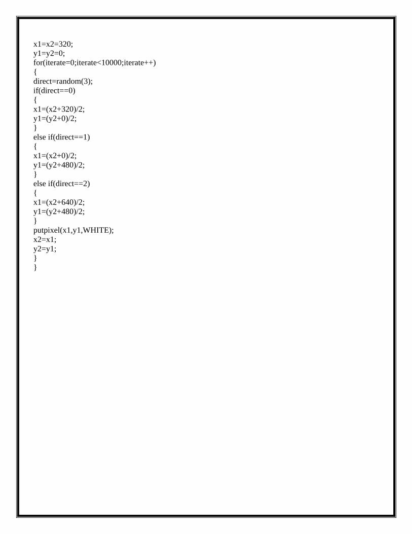
x1=x2=320;y1=y2=0;for(iterate=0;iterate<10000;iterate++){direct=random(3);if(direct==0){x1=(x2+320)/2;y1=(y2+0)/2;}else if(direct==1){x1=(x2+0)/2;y1=(y2+480)/2;}else if(direct==2){x1=(x2+640)/2;y1=(y2+480)/2;}putpixel(x1,y1,WHITE);x2=x1;y2=y1;}}
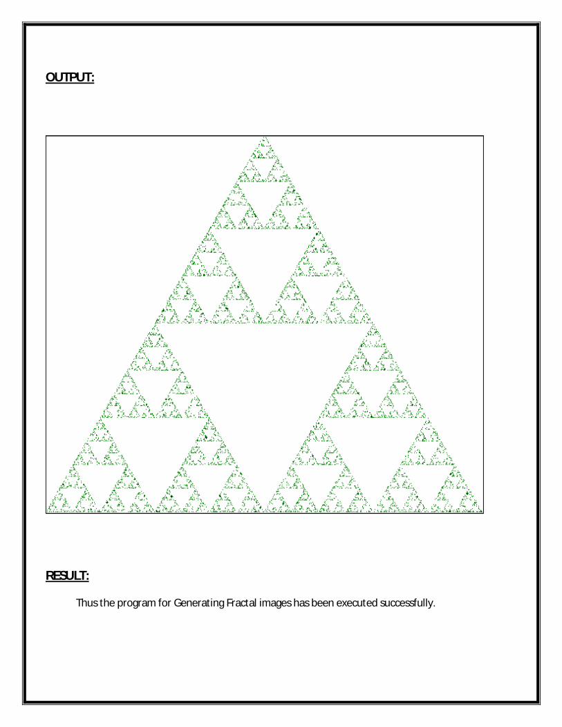
OUTPUT:
RESULT: Thus the program for Generating Fractal images has been executed successfully.
Recommended


![Scheme of INSTRUCTION and EVALUATION [Semester wise] · PDF fileScheme of INSTRUCTION and EVALUATION [Semester wise] FIRST SEMESTER: ... Theory Practical ... DDA algorithm, Bresenham’s](https://img.pdfslide.us/doc/110x75/5a9e448f7f8b9a75458ccf4e/scheme-of-instruction-and-evaluation-semester-wise-of-instruction-and-evaluation.jpg)