http://journals.cambridge.org Downloaded: 13 May 2014 IP address: 131.215.10.13
Compressive response of vertically aligned carbon nanotube filmsgleaned from in situ flat-punch indentations
Siddhartha Pathaka) and Nisha MohanMaterials Science, California Institute of Technology (Caltech), Pasadena, California 91125
Parisa Pour Shahid Saeed AbadiGeorge W. Woodruff School of Mechanical Engineering, Georgia Institute of Technology, Atlanta, Georgia 30332
Samuel Graham and Baratunde A. ColaGeorge W. Woodruff School of Mechanical Engineering, Georgia Institute of Technology, Atlanta, Georgia 30332;and School of Materials Science and Engineering, Georgia Institute of Technology, Atlanta, Georgia 30332
Julia R. GreerMaterials Science, California Institute of Technology (Caltech), Pasadena, California 91125
(Received 31 March 2012; accepted 28 September 2012)
We report the mechanical behavior of vertically aligned carbon nanotube films, grown on Sisubstrates using atmospheric pressure chemical vapor deposition, subjected to in situ largedisplacement (up to 70 lm) flat-punch indentations. We observed three distinct regimes in theirindentation stress–strain curves: (i) a short elastic regime, followed by (ii) a sudden instability,which resulted in a substantial rapid displacement burst manifested by an instantaneous verticalshearing of the material directly underneath the indenter tip by as much as 30 lm, and(iii) a positively sloped plateau for displacements between 10 and 70 lm. In situ nanomechanicalindentation experiments revealed that the shear strain was accommodated by an array of coiledcarbon nanotube “microrollers,” providing a low-friction path for the vertical displacement.Mechanical response and concurrent deformation morphologies are discussed in the foam-likedeformation framework with a particular emphasis on boundary conditions.
I. INTRODUCTION
Considerable efforts have been dedicated to explorethe deformation mechanisms of vertically aligned carbonnanotube (VACNT) forests, in part motivated by theirwide range of potential applications in areas such asenergy dissipation devices, electrical interconnects, ther-mal interface materials, microelectromechanical systems,and microelectronics.1–6 To date, instrumented indenta-tion has been a commonmethod for testing the mechanicalbehavior of VACNT films on substrates. However, due tothe limitations of the displacement actuators, most of theexisting studies are limited to shallow indentation depths(and strains), varying from a few hundred nanometers toseveral micrometers. Additionally, while VACNT forestfilms may have millimeter-sized lateral and verticaldimensions, they are composed of individual nanotubeswith diameters in the nanometer range, which drivestheir mechanical response to be distinct from monolithicmaterials. Hence, the accurate estimation of the contactarea between the VACNT film and the commonly usedparabolic7,8 and pyramidal7 indenter tip geometries,
necessary for indentation data analysis, poses a significantchallenge.
In this work, we utilize flat-punch diamond indentertips, resulting in a constant contact area with the sample,to conduct large displacement indentations into VACNTfilms grown using atmospheric pressure chemical vapordeposition (APCVD). Using both on-edge in situ and in-bulk ex situ flat-punch indentations, we examine thecombined quantitative information (load–displacement)along with the concomitant morphological changes. Toexplore the effect of lateral boundary constraints, thesefindings are compared with our previous report9 on uni-axial compressions of the same APCVD-grown VACNTspatterned into cylindrical bundles.
Mechanical response of VACNTs is a complex phe-nomenon occurring across multiple length scales due toits hierarchical structure. The collective behavior of thesematerials is expected to rely heavily on the properties ofthe individual carbon nanotubes (CNTs), as well as onthe variations in the collective intertube interactions andinherent property gradients of the microstructure, whichin turn are dictated by their synthesis techniques.10–12
A wide range of mechanical behavior has been reported inVACNTs as a result of such variations in their micro-structure. These include modulus and buckling strengthsranging from sub-MPa13,14 to tens of MPa15–17 to GPa,8,18
a)Address all correspondence to this author.e-mail: [email protected], [email protected]
DOI: 10.1557/jmr.2012.366
J. Mater. Res., Vol. 28, No. 7, Apr 14, 2013 �Materials Research Society 2012984
http://journals.cambridge.org Downloaded: 13 May 2014 IP address: 131.215.10.13
as well as a complete gamut of recoverability—from nearly100% recovery even after large deformations5,9,13,19,20 topermanent distortion even at modest strains.2,11,17,21,22
Such drastic differences in properties make it impracticalto compare VACNTs synthesized by nonidentical growthtechniques. In this work we focus on VACNTs grown byAPCVD technique23 and describe their response underindentation. These results are contrasted with our pre-vious work on uniaxial compressions of 30 lm diameter�30 lm tall cylindrical bundles.9 The APCVD VACNTbundles are known to exhibit three distinct regimes in theircompressive stress–strain curves: (i) a short initial elasticsection, followed by (ii) a sloped plateau with character-istic wavy features corresponding to localized buckleformation, and (iii) a densification characterized by a rapidstress increase—all of which liken their deformation tothat of a typical foam.5,9,11 Unlike foams, however, thecompressive strain in VACNTs is accommodated entirelyvia the formation of localized folds or buckles formingprogressively along their lengths.5,11,16,22,24,25 Duringcompression of our particular APCVD VACNT system,such localized buckles fully recovered upon load releaseeven from relatively large strains of 60–80% (i.e., theonset of densification) under fast displacement rates of1000 nm/s. In addition, repeated cycling also revealeda distinctive hysteresis behavior for the VACNT bundle incompression, suggesting energy dissipation in everycycle.9 However, since these properties were mainlydocumented for short height APCVD VACNTs underuniaxial compression, it is still largely unknown whetherthey demonstrate similar lucrative mechanical propertiesunder different loading and boundary conditions.
In this work, we focus on the deformation response of142-lm-tall APCVD-grown VACNT films under largedisplacement flat-punch indentations and compare it withthat of uniaxial compressions of ;30 � 30 lm (height �diameter) cylindrical pillars patterned into the samestarting material. Thus, we directly compare the influenceof the boundary conditions posed by the presence orabsence of the external matrix. We use both an in situnanoindentation methodology to observe the on-edgedeformation in real time using a custom-built in situnanomechanical deformation instrument, SEMentor,26 aswell as more traditional ex situ indentation methods.Recent work by our group9,11,23 and others16,24 showedthe efficacy of conducting in situ compressions inside thescanning electron microscope (SEM), which allows foruninterrupted observation of the real-time evolution ofdeformation morphology while simultaneously recordingload versus displacement data. Unlike compressionexperiments, where the indenter tip applies an axial loadto an individual structure readily visible in SEM, in situindentation experiments have to be conducted on theedge of the sample, as opposed to in bulk, to facilitateuninhibited inspection of the material cross section.23
Although boundary conditions and constraints associatedwith such on-edge tests are different from those duringin-bulk indentations, they are instrumental in providinguseful information on morphological evolution in deform-ing VACNTs, not easily obtainable by other methods.
II. MATERIALS AND METHODS
A. CNT growth
VACNT films with thicknesses between 25 and 142 lmwere grown using APCVD technique in a commercialchemical vapor deposition (CVD) system (Black MagicPro 40; Aixtron SE, Herzogenrath, Germany) as describedin detail in Ref. 23. A trilayer catalyst of Ti (30 nm)/Al(10 nm)/Fe (3 nm) was deposited by electron beamevaporation on Si substrates to seed the growth of theVACNT films. A gas mixture of 160/100/7500 sccm ofC2H2/H2/N2 was used to maintain the chamber pressure at750 mbar during growth, which occurred at ;750 °C.Multiwall CNTs, with an average diameter of 8.86 2.1 nm(average 6 standard deviation) and average mass density(CNT mass divided by volume) of ;80 mg/cm3, wereproduced by this process.23
B. Ex situ indentation tests
Two different VACNT films with thicknesses of ;142and 25 lm were selected for large displacement cyclicindentation tests. The indentation experiments were per-formed using the XP module of Agilent’s nanoindenterG200 (Santa Clara, CA) with adjustable software controlmethods as described in Ref. 11. Tests were performed inair using a custom-made cylindrical diamond flat punchwith ;120 lm diameter and ;80 lm height. For the142-lm-thick VACNT sample, indentations were performedunder a constant displacement control to varying indentationdepths up to a maximum penetration depth of around 70 lm(restricted by the height limitations of the diamond flatpunch). For the thinner samples, the maximum depth waslimited to 90% of the film thickness. Tests were conducted inthe interior of the samples (i.e., away from the sample edge)at three different constant displacement rates: 10, 100, and1000 nm/s. Typically, five unload–reload cycles wereperformed at each displacement level. No hold time wasapplied at themaximum loads tomaintain the cyclic nature ofthe tests. Minimum of 10 tests were conducted at eachdisplacement rate. The indents were spaced at least 500 lmapart to eliminate any possible proximity effects.
C. In situ SEM indentation experiments
To visualize the morphological changes in the VACNTsamples during indentation and correlate them with theconcurrent load–displacement data, in situ tests wereconducted in a custom-built mechanical deformation in-strument, SEMentor,26 composed of a nanomechanical
S. Pathak et al.: Compressive response of VACNT films gleaned from in situ flat-punch indentations
J. Mater. Res., Vol. 28, No. 7, Apr 14, 2013 985
http://journals.cambridge.org Downloaded: 13 May 2014 IP address: 131.215.10.13
dynamic contact module (Agilent Corp., Santa Clara, CA)inside a SEM (Quanta 200; FEI, Hillsboro, OR). Tests inSEMentor were conducted with a conductive diamond flatpunch with a rectangular flat cross section of ;60 � 80lm. The loading axis in SEMentor is inclined at ;86°with respect to the electron beam, thus allowing contin-uous observation of the deformation morphology of theVACNT film cross section during the on-edge in situexperiments. Importantly, the outer constraints in on-edgeindentations are different from those during in-bulk tests,and therefore, their stress–strain behavior is expected to bedifferent, as well. SEM observations were recorded asa video file at 30 frames/s capture rate and synchronizedwith the indentation data to provide a real-time correlationbetween each video frame and the corresponding positionon the load–displacement curve (see video files S1 and S2,shown at 15 and 10 times their original speeds, respec-tively, in the supporting online material). SEMentor testswere conducted to a maximum penetration depth of 30 lm(instrument limit). In addition, while nominally the experi-ments performed in both G200 and SEMentor are identi-cal, one notable difference is that SEMentor tests areconducted in a vacuum environment while those in G200are conducted in air. Further, in SEMentor experiments,the samples are constantly exposed to the electron beam,and they are oriented horizontally such that gravity is actingperpendicularly to the compression axis. Due to these subtledifferences between the two instruments, the SEMentor-generated results were used only for visualization purposesin this study, while all data analyseswere performed on testsconducted in air in the G200 nanoindenter.
D. Data analysis
The applied load, P, and measured displacement, h,were corrected for machine compliance following theprocedure outlined in detail in Ref. 11. We assumednegligible friction between the indenter sidewalls andthe VACNT matrix—a reasonable approximation basedon previous reports.27,28 The initial loading portion ina typical flat-punch indentation experiment often suffersfrom misalignment issues between the indenter tip andthe sample surface requiring special care in reliable extrac-tion of useful properties. On the other hand, applying theHertzian contact model to the initial unloading segmentof the measured load–displacement curve permits a rea-sonable estimation of the Young’s modulus29,30:
Eeff ¼ffiffiffip
p2
SffiffiffiA
p ¼ S
2a;
1Eeff
¼ 1� m2sEs
þ 1� m2iEi
;
ð1Þwhere Eeff denotes the effective modulus of the combinedindenter–specimen system, S(5dP/dh) is the stiffnessmeasured from the slope of the initial 30% of the
unloading load–displacement curve, v and E are thePoisson’s ratio and the Young’s modulus, respectively,and the subscripts s and i refer to the specimen and theindenter, respectively. Following the common nanoinden-tation protocols, we chose the modulus of 1041 GPa andPoisson’s ratio of 0.07 for the diamond indenter tip. Sincethe APCVD-grown VACNT bundles have been shown toexhibit foam-like deformation with minimal lateral expan-sion under compressive load,9 we assume a vanishingPoisson’s ratio of v5 0 for the VACNTs as has also beensuggested previously.31 We note that this choice may bean approximation since the deformation in VACNTs ishighly localized. However, the error introduced is notexpected to be significant since the accuracy of Es dependsonly weakly on v [see Eq. (1)]; e.g., a change in v from0 to 0.3 causes only a 5.3% error in Es.
We also note that Eq. (1) treats the overall materialbehavior as that of an isotropic continuum medium,according to the inherent assumptions of the Hertz’s theory.VACNTs, on the other hand, demonstrate varying degreesof anisotropy at each level of its hierarchical microstructure(see Fig. 1), rendering our calculations of indentationmoduli an approximation rather than an exact value.Nevertheless, isotropic continuum framework has beenpreviously utilized in developing the constitutive relationsin VACNTs11 and foams31 and appears to have accuratelycaptured the qualitative features of outer deformation pro-file and the stress–strain curves. Despite the discreteconstituents and apparent vertical alignment at low magni-fication, the continuum foundation was motivated by thenearly isotropic network of CNTs as revealed by images ator above magnifications of 240,000x [Fig. 1(c)] and above.
We define the percentage recovery (R) as the displace-ment recovered at the end of each cycle with respect to themaximum displacement, i.e., R ¼ hmax�hunload
hmax, where hmax is
the maximum displacement at the end of loading andhunload is the displacement after unloading to 10% of themaximum load in each cycle.
The loss coefficient, g (a dimensionless quantity),measures the degree to which a material dissipates energyand is calculated as32:
g ¼ DUi
2pU1; U ¼
Zrmax
0
rinddeind � 12r2max
Es;
DU ¼I
rinddeind ; ð2Þ
where U1 is the elastic energy stored in the material whenit is loaded elastically to a stress rmax in the 1st cycle andDUi is the energy dissipated in the ith load–unload cycle[see Fig. 5(d)].
To compare the indentation response of VACNTs to itsstress–strain behavior under compression, we define the
S. Pathak et al.: Compressive response of VACNT films gleaned from in situ flat-punch indentations
J. Mater. Res., Vol. 28, No. 7, Apr 14, 2013986
http://journals.cambridge.org Downloaded: 13 May 2014 IP address: 131.215.10.13
average indentation stress (rind) and strain (eind) under aflat-punch cylindrical indenter of contact diameter 2a andcontact area A as given below.33 In Eq. (3), the indentationresponse is assumed to free of any substrate effects:
rind ¼ P
A¼ P
pa2; eind ¼ h
2a: ð3Þ
E. Viscoelastic characterization
The viscoelastic properties of the VACNT film weremeasured following the procedure outlined in Ref. 11. Inthis method, the indenter is loaded into the sample in air ata constant displacement rate of 100 nm/s up to a specifiedindentation depth where the indenter head is oscillated at;8 nm amplitude across a range of frequencies from 1 to50 Hz. The cutoff frequency of 50 Hz is dictated by theinstrumental limit, as detailed in Refs. 11 and 34. Theprocedure was repeated at seven different constant in-dentation depths: from 5 to 70 lm.
Viscoelastic materials are commonly characterized bytheir storage (E9) and loss (E0) moduli, where the formerrepresents the stored energy or the elastic response and thelatter corresponds to the amount of energy dissipated, orthe viscous response, as well as their ratio—tand. Assum-ing linear viscoelastic behavior, these terms can becomputed following the calculations described in Refs.34–37 as follows:
E9 ¼ k9
ffiffiffip
p2b
1� m2sffiffiffiA
p ; k9 ¼ F0
u0
�������� cosu� F0
u0
��������air
cosuair;
E0 ¼ k0
ffiffiffip
p2b
1� m2sffiffiffiA
p ; k0 ¼ F0
u0
�������� sinu� F0
u0
��������air
sinuair ;
tan d ¼ E0
E9: ð4Þ
Here, k9 and k0 are the storage and loss stiffnesses of thesample, obtained by finding the real and complex parts,respectively, of the stiffness differences between oscillat-ing the indenter head on the sample at a fixed displacementand in air at the same raw displacement, and b is a constant(51 for a flat-punch indenter). F0 and u0 are the load anddisplacement oscillation amplitudes, respectively, andu isthe phase angle between the load and displacementoscillations. We note that the accuracy in the values ofE9 and E0 in Eq. (4) can be affected by several factors:uncertainties in Poisson’s ratio, since it may be frequencydependent, and ambiguity in contact area, especially atshallower indentation depths, where full contact may nothave been established. On the other hand, calculation oftand is independent of the contact area and thus is ideallysuited as a measure of the viscoelasticity of the indentedmaterial.8,38
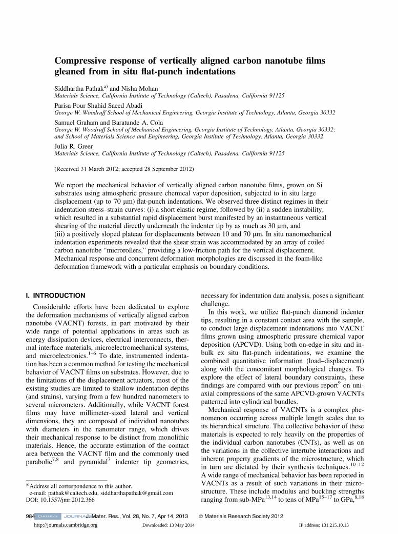
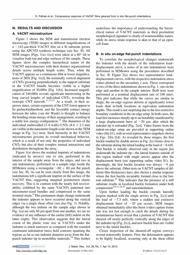
FIG. 1. SEM images reveal the hierarchical morphology of the(a) 141.5-lm-thick VACNT films (magnification 260x), which consistof (b) nominally vertical aligned CNTs visible at a lower magnificationof 30kx, and (c) a complex intertwined network seen at highermagnifications of 240kx. SEM pictures are taken at a 60° tilt angle.(c inset) Individual multiwalled CNTs of outer diameter 8.8 6 2.1 nm(average 6 standard deviation) are visible in the TEM image.
S. Pathak et al.: Compressive response of VACNT films gleaned from in situ flat-punch indentations
J. Mater. Res., Vol. 28, No. 7, Apr 14, 2013 987
http://journals.cambridge.org Downloaded: 13 May 2014 IP address: 131.215.10.13
III. RESULTS AND DISCUSSION
A. VACNT microstructure
Figure 1 shows the SEM and transmission electronmicroscopy (TEM) images at different magnifications ofa ;142-lm-thick VACNT film on a Si substrate grownusing the APCVD synthesis technique (see Sec. II). AllSEM images [Figs. 1(a)–1(c)] were taken at a 60° tilt tovisualize both top and edge surfaces of the sample. Thesefigures show the complex hierarchical nature of theVACNT microstructure with their distinct organizationaldetails across multiple length scales. Thus, while theVACNT appears as a continuous film at lower magnifica-tions of 260x [Fig. 1(a)], the nominally vertical alignmentof CNTs growing perpendicularly to the support substratein the VACNT bundle becomes visible at a highermagnification of 30,000x [Fig. 1(b)]. Increased magnifi-cation of 240,000x reveals significant intertwining in thelong curved lengths of individual CNTs, revealing theisotropic CNT network.11,12,31 As a result, in their as-grown states, certain segments of the CNT forest appear tobe prebuckled/prebent, and the favorable contact energybetween the tubes (van der Waals) is thought to balancethe bending strain energy of their arrangement, resulting ina stable low energy configuration.15 The diameters of theindividual multiwalled (3–6 walls) CNTs (8.8 6 2.1 nm)are visible at the nanometer length scale shown in the TEMimage in Fig. 1(c) inset. Such hierarchy in the VACNTmicrostructure governs its overall mechanical behavior,which is a result of not only the properties of individualCNTs but also of their complex mutual interactions anddistribution throughout the array.
Figure 1(a) shows the residual imprints of indentations(indicated by arrows): one ex situ, performed in theinterior of the sample away from the edges, and two insitu indentations, performed on a sample edge inside theSEMentor using a rectangular ;60 � 80 lm flat punch(see Sec. II). As can be seen clearly from this image, theindentations left a significant imprint on the surface of theVACNT film, suggesting marginal postmortem elasticrecovery. This is in contrast with the nearly full recover-ability exhibited by the same VACNTs patterned intomicrometer-sized bundles and compressed to the samenominal strain.9 This permanent shape change underneaththe indenter appears to have occurred along the verticaledges via a single shear offset (see also Fig. 3). Notably,although the two indents on the sample edge shown inFig. 1(a) are only 60 lm apart from one another, we see noevidence of any influence of the earlier (left) indent on thelatter (right). This observation suggests that the lateralextent of the plastic zone size in VACNTs under theindenter is much narrower as compared with the roundedcontinuum indentation stress field contours spanning theregions as far as one indenter diameter away from the flat-punch indenter tip in monolithic materials.39 This further
underlines the importance of understanding the hierar-chical nature of VACNT materials as their postindentmorphological signature is clearly of nonmonolithic nature,while its stress–strain response is akin to that of an open-cell foam.
B. In situ on-edge flat-punch indentations
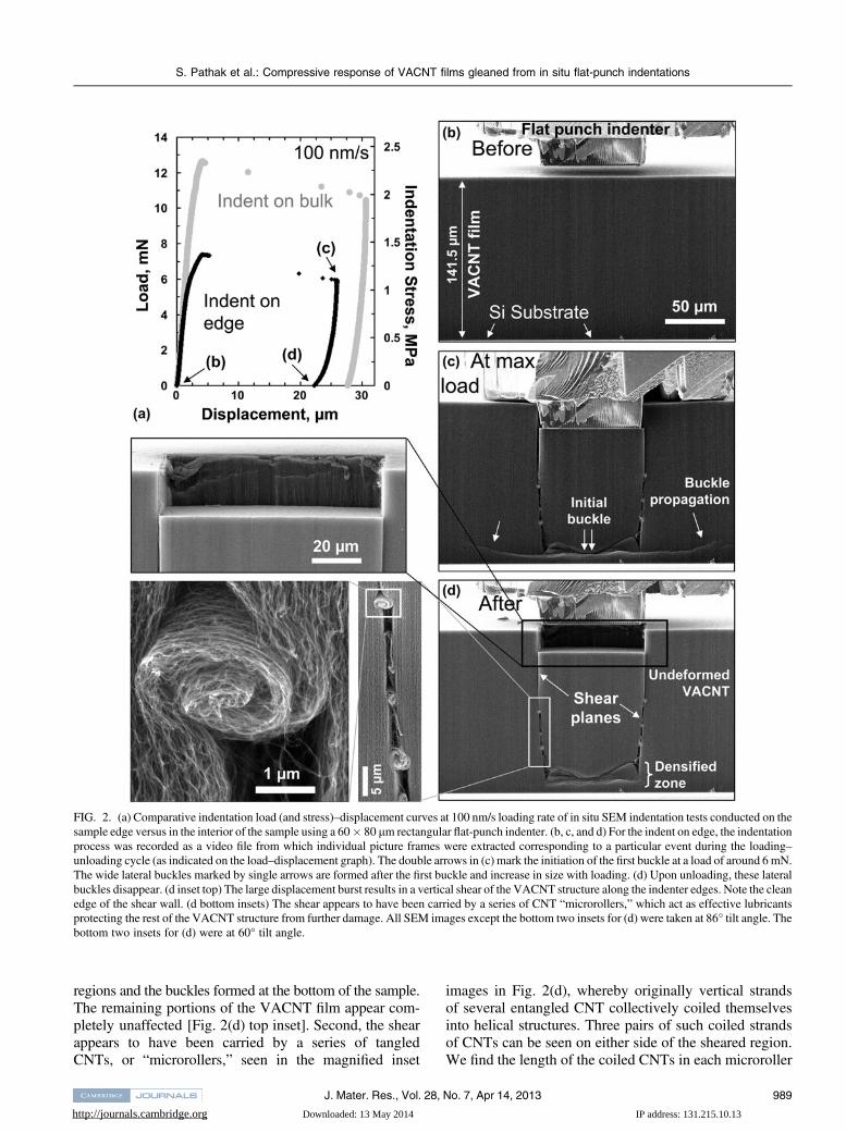
To correlate the morphological changes underneaththe indenter with the details of the indentation load–displacement curve, a series of in situ indentations wereperformed in SEMentor using the procedures describedin Sec. II. Figure 2(a) shows two representative load–displacement curves, with the respective indentation stressvalues plotted on the secondary y axis. These correspondto two of the three indentations shown in Fig. 1: one on theedge and another in the sample interior. Both tests wereperformed at a nominal displacement rate of 100 nm/s.This plot indicates that while the curves are similar inshape, the on-edge regions deform at significantly lowerloads than in-bulk locations at equivalent indentationdepths. This result is not surprising due to the less restrictiveboundary conditions in the on-edge setup. In both cases, theload first increases steeply up to an instability manifested bya large displacement burst of ;20 lm, after which theindenter tip is unloaded [Fig. 2(a)]. Video frames from theindent-on-edge setup are provided in supporting onlinevideo (file S1), with several representative snapshots shownin Figs. 2(b)–2(d). As revealed by these images, the firstbuckle marked by double arrows in Fig. 2(c) forms close tothe substrate during the initial loading at the load of;6mN.This buckle is initially observed only in the region justunderneath the indenter tip—the lateral features outside ofthis region marked with single arrows appear after thedisplacement burst (see supporting online video S1). In-terestingly, the first buckle location was always ;9 lmabove the substrate. Other tests on VACNT samples of dif-ferent film thicknesses have also shown a similar responsewhere the first buckle invariably formed close to the bot-tom substrate.23 This indicates that the presence of a stiffsubstrate results in localized buckle formation under bothcompression5,9,11,16,22 and nanoindentation.
Upon further loading the buckle extends laterally[region marked with the single arrows in Fig. 2(c)] untilthe load of ;7.3 mN, where a sudden and extensivedisplacement burst of ;20 lm occurs. SEM imagesobtained immediately after this burst (video capture framerate was not fast enough to catch the details during theinstantaneous burst) reveal that a portion of VACNT filmsheared off nearly perfectly vertically along the edges ofthe indenter tip [Fig. 2(c)], and new buckle lines are visiblenext to the initial buckles.
Closer inspection of the sheared-off region conveysseveral noteworthy features. First, the deformation appearsto be highly localized, occurring only at the shear offset
S. Pathak et al.: Compressive response of VACNT films gleaned from in situ flat-punch indentations
J. Mater. Res., Vol. 28, No. 7, Apr 14, 2013988
http://journals.cambridge.org Downloaded: 13 May 2014 IP address: 131.215.10.13
regions and the buckles formed at the bottom of the sample.The remaining portions of the VACNT film appear com-pletely unaffected [Fig. 2(d) top inset]. Second, the shearappears to have been carried by a series of tangledCNTs, or “microrollers,” seen in the magnified inset
images in Fig. 2(d), whereby originally vertical strandsof several entangled CNT collectively coiled themselvesinto helical structures. Three pairs of such coiled strandsof CNTs can be seen on either side of the sheared region.We find the length of the coiled CNTs in each microroller
FIG. 2. (a) Comparative indentation load (and stress)–displacement curves at 100 nm/s loading rate of in situ SEM indentation tests conducted on thesample edge versus in the interior of the sample using a 60� 80 lm rectangular flat-punch indenter. (b, c, and d) For the indent on edge, the indentationprocess was recorded as a video file from which individual picture frames were extracted corresponding to a particular event during the loading–unloading cycle (as indicated on the load–displacement graph). The double arrows in (c) mark the initiation of the first buckle at a load of around 6mN.The wide lateral buckles marked by single arrows are formed after the first buckle and increase in size with loading. (d) Upon unloading, these lateralbuckles disappear. (d inset top) The large displacement burst results in a vertical shear of the VACNT structure along the indenter edges. Note the cleanedge of the shear wall. (d bottom insets) The shear appears to have been carried by a series of CNT “microrollers,” which act as effective lubricantsprotecting the rest of the VACNT structure from further damage. All SEM images except the bottom two insets for (d) were taken at 86° tilt angle. Thebottom two insets for (d) were at 60° tilt angle.
S. Pathak et al.: Compressive response of VACNT films gleaned from in situ flat-punch indentations
J. Mater. Res., Vol. 28, No. 7, Apr 14, 2013 989
http://journals.cambridge.org Downloaded: 13 May 2014 IP address: 131.215.10.13
to be ;6 lm, and thus, the total displacement carried bythe rollers is ;18 lm. This distance is in reasonableagreement with the displacement burst extent of ;20 lmshown in Fig. 2(a). We hypothesize that these microrollersprovide a low-friction path during the shear process.
The shear event and the formation of the CNT micro-rollers [Figs. 2(c) and 2(d)] are unique characteristics seenonly in the intertwined VACNT systems. Neitherfoams,40,41 where the deformation is confined only toregions directly beneath the indenter, nor noninteractingVACNTs,42 where such shear would propagate withoutany microroller formation, show the unique features seenin Fig. 2. As shown before in Fig. 1, the hierarchical designof these materials results in considerable interlinkingbetween the individual struts. Thus, in spite of theirnominally vertical structure, the CNTs along the shearplane of the VACNT film can perform as highly efficientlubricants by collectively coiling themselves and therebycarrying the shear strain in response to axial loading. Theeffectiveness of this “lubrication process” is evidenced bythe very rapid nature of the burst and the resulting shearevent under the indenter. Comparing SEM images atmaximum load and after unload [Figs. 2(c) and 2(d)]shows that this shear event caused permanent damage tothe material structure, as unloading the indenter tip resultsin minimal recovery. Upon unloading, the CNT micro-rollers did not uncoil, and the only observed difference inthe morphology of the before and after deformationmaterial was that the buckle contours, which extendedlaterally beyond the sheared block, disappeared uponunloading.
C. Ex situ in-bulk large displacement indentations
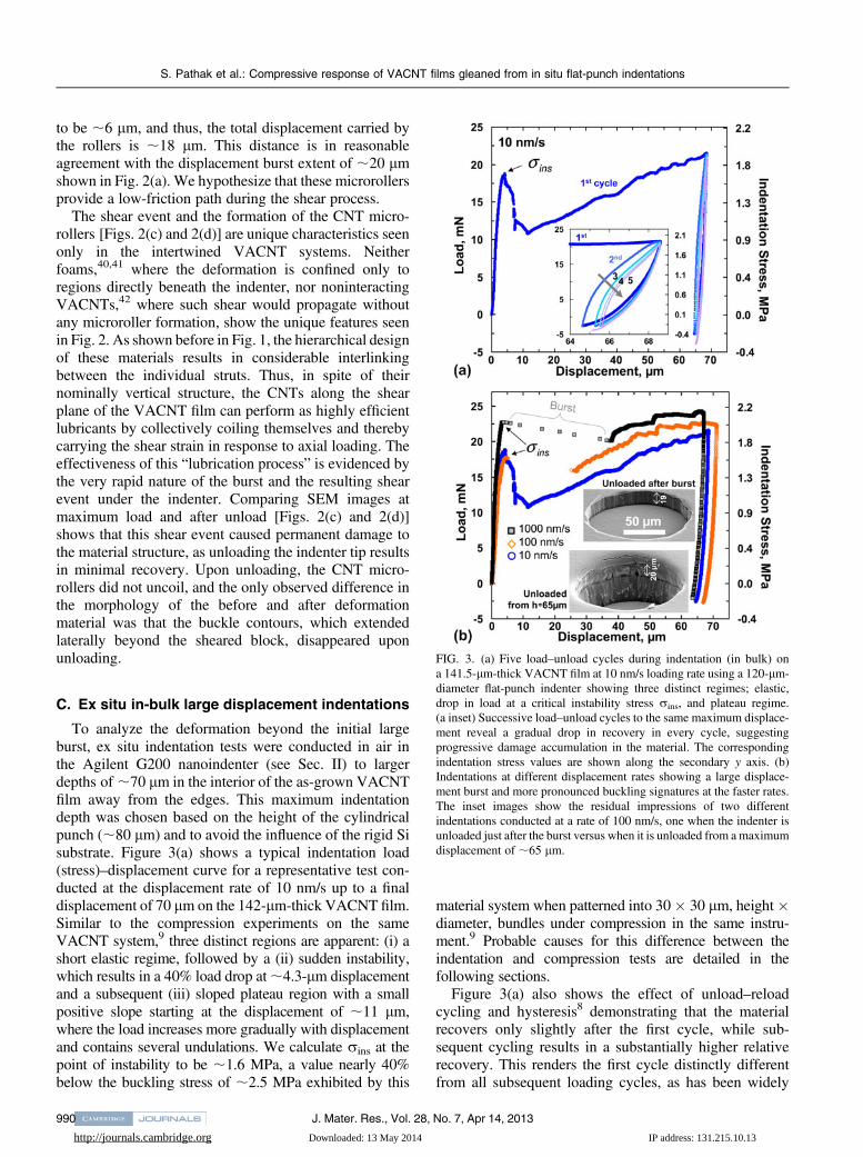
To analyze the deformation beyond the initial largeburst, ex situ indentation tests were conducted in air inthe Agilent G200 nanoindenter (see Sec. II) to largerdepths of ;70 lm in the interior of the as-grown VACNTfilm away from the edges. This maximum indentationdepth was chosen based on the height of the cylindricalpunch (;80 lm) and to avoid the influence of the rigid Sisubstrate. Figure 3(a) shows a typical indentation load(stress)–displacement curve for a representative test con-ducted at the displacement rate of 10 nm/s up to a finaldisplacement of 70 lm on the 142-lm-thick VACNT film.Similar to the compression experiments on the sameVACNT system,9 three distinct regions are apparent: (i) ashort elastic regime, followed by a (ii) sudden instability,which results in a 40% load drop at;4.3-lm displacementand a subsequent (iii) sloped plateau region with a smallpositive slope starting at the displacement of ;11 lm,where the load increases more gradually with displacementand contains several undulations. We calculate rins at thepoint of instability to be ;1.6 MPa, a value nearly 40%below the buckling stress of ;2.5 MPa exhibited by this
material system when patterned into 30� 30 lm, height�diameter, bundles under compression in the same instru-ment.9 Probable causes for this difference between theindentation and compression tests are detailed in thefollowing sections.
Figure 3(a) also shows the effect of unload–reloadcycling and hysteresis8 demonstrating that the materialrecovers only slightly after the first cycle, while sub-sequent cycling results in a substantially higher relativerecovery. This renders the first cycle distinctly differentfrom all subsequent loading cycles, as has been widely
FIG. 3. (a) Five load–unload cycles during indentation (in bulk) ona 141.5-lm-thick VACNT film at 10 nm/s loading rate using a 120-lm-diameter flat-punch indenter showing three distinct regimes; elastic,drop in load at a critical instability stress rins, and plateau regime.(a inset) Successive load–unload cycles to the same maximum displace-ment reveal a gradual drop in recovery in every cycle, suggestingprogressive damage accumulation in the material. The correspondingindentation stress values are shown along the secondary y axis. (b)Indentations at different displacement rates showing a large displace-ment burst and more pronounced buckling signatures at the faster rates.The inset images show the residual impressions of two differentindentations conducted at a rate of 100 nm/s, one when the indenter isunloaded just after the burst versus when it is unloaded from amaximumdisplacement of ;65 lm.
S. Pathak et al.: Compressive response of VACNT films gleaned from in situ flat-punch indentations
J. Mater. Res., Vol. 28, No. 7, Apr 14, 2013990
http://journals.cambridge.org Downloaded: 13 May 2014 IP address: 131.215.10.13
observed for CNT foams.4,5,9 The inset in Fig. 3(a) showsthe zoomed-in load–unload segments during cycling andindicates that both the amount of hysteresis, correspondingto the energy dissipated per cycle, and the recovereddisplacement after unloading diminish with each sub-sequent cycle. Although each cycle was specified to beunloaded to only 10% of the maximum load from theprevious cycle, in some cases, the applied loads weremeasured as slightly negative, likely due to the adhesionbetween the VACNT tips and the diamond indenter.12,15
Several indentation load (and stress)–displacementcurves for three different displacement rates are shownin Fig. 3(b). Although the general behavior across thedifferent rates is similar in appearance, several importantdistinctions can be made. For example, at the fasterloading rates of 100 and 1000 nm/s, there appears to bea rapid extensive displacement burst of ;20 lm or largerimmediately upon attaining rins, resulting in a temporaryloss of contact between the sample and the indenter tip.The burst size appears to increase with loading rate. This isin contrast to the gradual load removal, where contact ismaintained at all times, shown in the tests conducted at theslowest rate of 10 nm/s. Based on the in situ indentationtests described in Fig. 2, it appears that the burst may becaused by a rapid vertical shearing of the material directlyunderneath the indenter tip along the indenter edges.Indeed, when the test was stopped at the moment of theburst [top SEM image in Fig. 3(b) at 100 nm/s], weobserve the formation of a large imprint of depth;19 lmmirroring the shape of the indenter, with the residual depthequivalent to the displacement burst. Closer inspection ofthe imprints indicates that the material directly underneaththe indenter is mostly unperturbed, with all deformation—again—appearing to have been localized in the verticalshear region along the rim of contact between the sampleand the indenter tip.
Further loading beyond the first burst is characterizedby the reappearance of the sloped plateau. Such slopedplateau regions have been observed previously9,11 andwere attributed to an inherent property gradient in theVACNT microstructure along its height. Current authorshave reported a similar gradient to be present in APCVDVACNT films where both the CNT number and massdensities were found to vary as a function of the filmheight.23 It is, therefore, reasonable to assume that asimilar density variation is present in the samples de-scribed here, resulting in the indenter punch encounteringa denser, and hence stiffer, material in the deeper regions.This requires the application of a higher stress to form eachsuccessive buckle, leading to an increasing global slopein the plateau region. While the slopes of the plateauregion appear to be similar among all three rates shown inFig. 3(b), samples deformed at the faster rates sustainhigher stresses, a behavior considered typical for visco-elastic solids.43
The plateau region is composed of several undulationsor kinks for all three loading rates. Such features havebeen observed previously during in situ compressionexperiments of 60-lm-tall VACNT bundles11 and in exsitu tests,5,11,16,22,24,25 as well as more recently by thepresent authors for in situ compressions of 30 � 30 lmheight � diameter VACNT micropillars made from thesame APCVD process.9 The in situ compression studiesof Hutchens et al.11 revealed that the formation of eachundulation corresponded to the formation of localizedfolds or buckles along the pillar height, with the faster ratesshowing drops of larger amplitude.9,11 While—unlike incompression experiments—direct observation of buckleformation is not possible during indentation in the interiorof the sample, it is reasonable to assume that a simi-lar deformation mechanism operates during flat-punchindentations. Thus, the series of load drops in the load–displacement curves likely correspond to the coordinatedsequential lateral collapse events somewhere below theindenter, with the force required to cause them being muchsmaller than that of the initial instability.
Unloading from a depth of ;65–70 lm results in verylittle recovery as shown by the residual imprint in thebottom SEM image of Fig. 3(b) inset. The imprint alsoshows the remnant of the first large burst, which is seen asa shear line at a depth of ;20 lm along the walls of thecrater. The vertical walls of the indent imprint indicate aclear shearing of the VACNTs along the rim of theindenter.
D. Effect of substrate on buckle formation
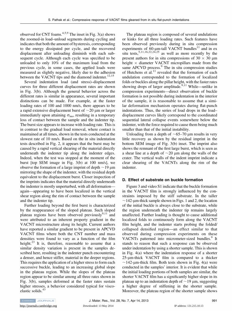
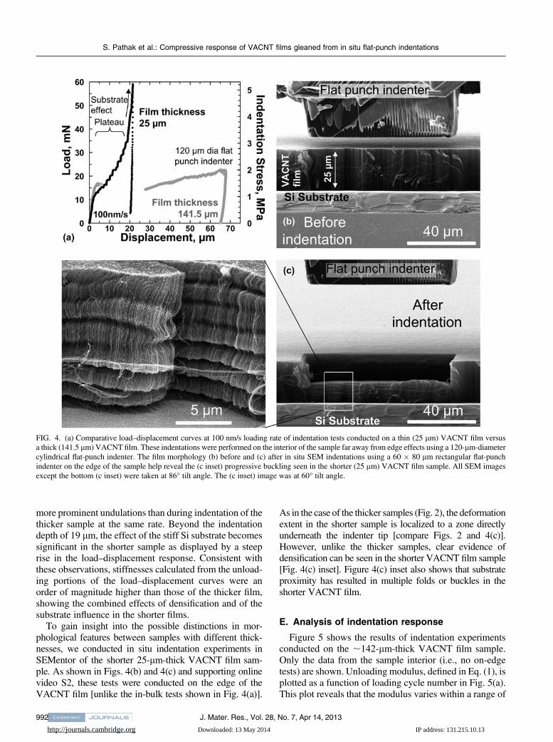
Figure 3 and video S1 indicate that the buckle formationin the VACNT film is strongly influenced by the con-straints imposed by the stiff substrate. In the taller;142-lm-thick sample shown in Figs. 1 and 2, the locationof the initial buckle is always close to the substrate, whilethe region underneath the indenter tip remains largelyunaffected. Further loading is thought to cause additionallocalized folds to continuously form along the VACNTfilm height, and the indenter starts probing the folded/collapsed densified region—an effect similar to thatobserved during compression experiments on theseVACNTs patterned into micrometer-sized bundles.9 Itstands to reason that such a response can be observedunder indentation by using a shorter sample. This is shownin Fig. 4(a) where the indentation response of a shorter25-lm-thick VACNT film is compared to a thicker;142-lm-thick film. Both tests shown in Fig. 4(a) wereconducted in the samples’ interior. It is evident that whilethe initial loading portions of both samples are similar, theshorter VACNT film has a significantly higher slope in itsplateau up to an indentation depth of;19 lm, suggestinga higher degree of stiffening in the shorter sample.Moreover, the plateau region of the shorter sample shows
S. Pathak et al.: Compressive response of VACNT films gleaned from in situ flat-punch indentations
J. Mater. Res., Vol. 28, No. 7, Apr 14, 2013 991
http://journals.cambridge.org Downloaded: 13 May 2014 IP address: 131.215.10.13
more prominent undulations than during indentation of thethicker sample at the same rate. Beyond the indentationdepth of 19 lm, the effect of the stiff Si substrate becomessignificant in the shorter sample as displayed by a steeprise in the load–displacement response. Consistent withthese observations, stiffnesses calculated from the unload-ing portions of the load–displacement curves were anorder of magnitude higher than those of the thicker film,showing the combined effects of densification and of thesubstrate influence in the shorter films.
To gain insight into the possible distinctions in mor-phological features between samples with different thick-nesses, we conducted in situ indentation experiments inSEMentor of the shorter 25-lm-thick VACNT film sam-ple. As shown in Figs. 4(b) and 4(c) and supporting onlinevideo S2, these tests were conducted on the edge of theVACNT film [unlike the in-bulk tests shown in Fig. 4(a)].
As in the case of the thicker samples (Fig. 2), the deformationextent in the shorter sample is localized to a zone directlyunderneath the indenter tip [compare Figs. 2 and 4(c)].However, unlike the thicker samples, clear evidence ofdensification can be seen in the shorter VACNT film sample[Fig. 4(c) inset]. Figure 4(c) inset also shows that substrateproximity has resulted in multiple folds or buckles in theshorter VACNT film.
E. Analysis of indentation response
Figure 5 shows the results of indentation experimentsconducted on the ;142-lm-thick VACNT film sample.Only the data from the sample interior (i.e., no on-edgetests) are shown. Unloading modulus, defined in Eq. (1), isplotted as a function of loading cycle number in Fig. 5(a).This plot reveals that the modulus varies within a range of
FIG. 4. (a) Comparative load–displacement curves at 100 nm/s loading rate of indentation tests conducted on a thin (25 lm) VACNT film versusa thick (141.5 lm) VACNT film. These indentations were performed on the interior of the sample far away from edge effects using a 120-lm-diametercylindrical flat-punch indenter. The film morphology (b) before and (c) after in situ SEM indentations using a 60 � 80 lm rectangular flat-punchindenter on the edge of the sample help reveal the (c inset) progressive buckling seen in the shorter (25 lm) VACNT film sample. All SEM imagesexcept the bottom (c inset) were taken at 86° tilt angle. The (c inset) image was at 60° tilt angle.
S. Pathak et al.: Compressive response of VACNT films gleaned from in situ flat-punch indentations
J. Mater. Res., Vol. 28, No. 7, Apr 14, 2013992
http://journals.cambridge.org Downloaded: 13 May 2014 IP address: 131.215.10.13
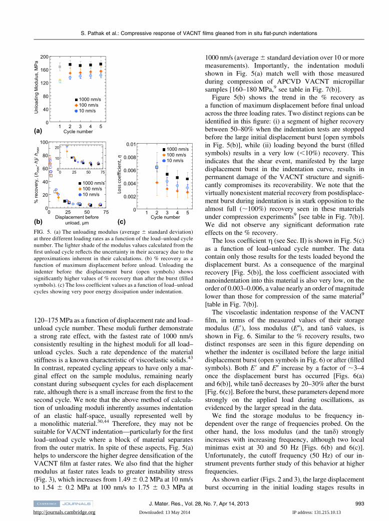
120–175MPa as a function of displacement rate and load–unload cycle number. These moduli further demonstratea strong rate effect, with the fastest rate of 1000 nm/sconsistently resulting in the highest moduli for all load–unload cycles. Such a rate dependence of the materialstiffness is a known characteristic of viscoelastic solids.43
In contrast, repeated cycling appears to have only a mar-ginal effect on the sample modulus, remaining nearlyconstant during subsequent cycles for each displacementrate, although there is a small increase from the first to thesecond cycle. We note that the above method of calcula-tion of unloading moduli inherently assumes indentationof an elastic half-space, usually represented well bya monolithic material.30,44 Therefore, they may not besuitable for VACNT indentation—particularly for the firstload–unload cycle where a block of material separatesfrom the outer matrix. In spite of these aspects, Fig. 5(a)helps to underscore the higher degree densification of theVACNT film at faster rates. We also find that the highermodulus at faster rates leads to greater instability stress(Fig. 3), which increases from 1.496 0.2 MPa at 10 nm/sto 1.54 6 0.2 MPa at 100 nm/s to 1.75 6 0.3 MPa at
1000 nm/s (average6 standard deviation over 10 or moremeasurements). Importantly, the indentation modulishown in Fig. 5(a) match well with those measuredduring compression of APCVD VACNT micropillarsamples [160–180 MPa,9 see table in Fig. 7(b)].
Figure 5(b) shows the trend in the % recovery asa function of maximum displacement before final unloadacross the three loading rates. Two distinct regions can beidentified in this figure: (i) a segment of higher recoverybetween 50–80% when the indentation tests are stoppedbefore the large initial displacement burst [open symbolsin Fig. 5(b)], while (ii) loading beyond the burst (filledsymbols) results in a very low (,10%) recovery. Thisindicates that the shear event, manifested by the largedisplacement burst in the indentation curve, results inpermanent damage of the VACNT structure and signifi-cantly compromises its recoverability. We note that thevirtually nonexistent material recovery from postdisplace-ment burst during indentation is in stark opposition to thealmost full (;100%) recovery seen in these materialsunder compression experiments9 [see table in Fig. 7(b)].We did not observe any significant deformation rateeffects on the % recovery.
The loss coefficient g (see Sec. II) is shown in Fig. 5(c)as a function of load–unload cycle number. The datacontain only those results for the tests loaded beyond thedisplacement burst. As a consequence of the marginalrecovery [Fig. 5(b)], the loss coefficient associated withnanoindentation into this material is also very low, on theorder of 0.003–0.006, a value nearly an order of magnitudelower than those for compression of the same material9
[table in Fig. 7(b)].The viscoelastic indentation response of the VACNT
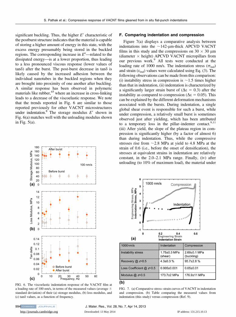
film, in terms of the measured values of their storagemodulus (E9), loss modulus (E0), and tand values, isshown in Fig. 6. Similar to the % recovery results, twodistinct responses are seen in this figure depending onwhether the indenter is oscillated before the large initialdisplacement burst (open symbols in Fig. 6) or after (filledsymbols). Both E9 and E0 increase by a factor of ;3–4once the displacement burst has occurred [Figs. 6(a)and 6(b)], while tand decreases by 20–30% after the burst[Fig. 6(c)]. Before the burst, these parameters dependmorestrongly on the applied load during oscillations, asevidenced by the larger spread in the data.
We find the storage modulus to be frequency in-dependent over the range of frequencies probed. On theother hand, the loss modulus (and the tand) stronglyincreases with increasing frequency, although two localminimas exist at 30 and 50 Hz [Figs. 6(b) and 6(c)].Unfortunately, the cutoff frequency (50 Hz) of our in-strument prevents further study of this behavior at higherfrequencies.
As shown earlier (Figs. 2 and 3), the large displacementburst occurring in the initial loading stages results in
FIG. 5. (a) The unloading modulus (average 6 standard deviation)at three different loading rates as a function of the load–unload cyclenumber. The lighter shade of the modulus values calculated from thefirst unload cycle reflects the uncertainty in their accuracy due to theapproximations inherent in their calculations. (b) % recovery as afunction of maximum displacement before unload. Unloading theindenter before the displacement burst (open symbols) showssignificantly higher values of % recovery than after the burst (filledsymbols). (c) The loss coefficient values as a function of load–unloadcycles showing very poor energy dissipation under indentation.
S. Pathak et al.: Compressive response of VACNT films gleaned from in situ flat-punch indentations
J. Mater. Res., Vol. 28, No. 7, Apr 14, 2013 993
http://journals.cambridge.org Downloaded: 13 May 2014 IP address: 131.215.10.13
significant buckling. Thus, the higher E9 characteristic ofthe postburst structure indicates that the material is capableof storing a higher amount of energy in this state, with theexcess energy presumably being stored in the buckledregions. The corresponding increase in E0—related to thedissipated energy—is at a lower proportion, thus leadingto a less pronounced viscous response (lower values oftand) after the burst. The post-burst decrease in tand islikely caused by the increased adhesion between theindividual nanotubes in the buckled regions when theyare brought into proximity of one another after buckling.A similar response has been observed in polymericmaterials like rubber,45 where an increase in cross-linkingleads to a decrease of the viscoelastic response. We notethat the trends reported in Fig. 6 are similar to thosereported previously for other VACNT microstructuresunder indentation.8 The storage modulus E9 shown inFig. 6(a) matches well with the unloading modulus shownin Fig. 5(a).
F. Comparing indentation and compression
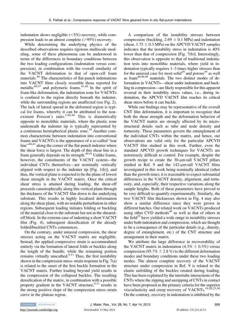
Figure 7(a) displays a comparative analysis betweenindentations into the ;142-lm-thick APCVD VACNTfilms in this study and the compressions on 30 � 30 lm(diameter � height) APCVD VACNT micropillars fromour previous work.9 All tests were conducted at theloading rate of 1000 nm/s. The indentation stress (rind)and strain (eind) values were calculated using Eq. (3). Thefollowing observations can be made from this comparison:(i) instability stress in compression is ;1.5 times higherthan that in indentation, (ii) indentation is characterized bya significantly larger strain burst of (De 5 0.3) after theinstability as compared to compression (De 5 0.05). Thiscan be explained by the different deformation mechanismsassociated with the bursts. During indentation, a singleglobal shear event is responsible for such a burst, whileunder compression, a relatively small burst is sometimesobserved just after yielding, which has been attributedto a temporary loss in the pillar–indenter contact.9,11
(iii) After yield, the slope of the plateau region in com-pression is significantly higher (by a factor of almost 6)than during indentation. Thus, while the compressivestresses rise from ;2.8 MPa at yield to 4.8 MPa at thestrain of 0.6 (i.e., before the onset of densification), thestresses at equivalent strains in indentation are relativelyconstant, in the 2.0–2.1 MPa range. Finally, (iv) afterunloading (to 10% of maximum load), the material under
FIG. 6. The viscoelastic indentation response of the VACNT film ata loading rate of 100 nm/s, in terms of the measured values (average 6standard deviation) of their (a) storage modulus, (b) loss modulus, and(c) tand values, as a function of frequency.
FIG. 7. (a) Comparative stress–strain curves of VACNT in indentationand compression. (b) Table comparing the measured values fromindentation (this study) versus compression (Ref. 9).
S. Pathak et al.: Compressive response of VACNT films gleaned from in situ flat-punch indentations
J. Mater. Res., Vol. 28, No. 7, Apr 14, 2013994
http://journals.cambridge.org Downloaded: 13 May 2014 IP address: 131.215.10.13
indentation shows negligible (,5%) recovery, while com-pression leads to an almost complete (.95%) recovery.
While determining the underlying physics of thedescribed observations requires rigorous multiscale mod-eling, some of these phenomena can be understood interms of the differences in boundary conditions betweenthe two loading configurations (indentation versus com-pression), in combination with the overall similarity ofthe VACNT deformation to that of open-cell foammaterials.46 The characteristics of flat-punch indentationsinto VACNT films closely resemble those reported formetallic40,47 and polymeric foams.41,46 In the spirit offoam-like deformation, the indentation zone for VACNTsis confined to the region directly beneath the indenter,while the surrounding regions are unaffected (see Fig. 2).The lack of lateral spread in the deformed region is typi-cal for foams, whereby it can be attributed to the non-existent Poisson’s ratio.2,40,46 This is diametricallyopposite to monolithic materials, where the plastic zoneunderneath the indenter tip is typically represented bya continuous hemispherical plastic zone.39 Another com-mon characteristic between indentation into conventionalfoams and VACNTs is the appearance of a so-called “tearline”40,41 along the corner of the flat-punch indenter wherethe shear force is largest. The depth of this shear line in afoam generally depends on its strength.40,41 Unlike foams,however, the constituents of the VACNT system—theindividual CNTs themselves—are nominally verticallyaligned with respect to the indenter tip [Fig. 1(b)], andthus, the vertical plane is expected to be the plane of lowestshear strength in the VACNT matrix. Once the criticalshear stress is attained during loading, the shear-offproceeds catastrophically along this vertical plane throughthe thickness of the VACNT film down to the underlyingsubstrate. This results in highly localized deformationalong the shear plane, with no notable perturbation in otherregions. Subsequent loading initiates folding or bucklingof the material close to the substrate but not in the sheared-off block. In the extreme case of indenting a short VACNTfilm (Fig. 4), subsequent densification of the alreadyfolded/buckled CNTs commences.
On the contrary, under uniaxial compression, the shearstresses acting on the VACNT matrix are negligible.Instead, the applied compressive strain is accommodatedentirely via the formation of lateral folds or buckles alongthe length of the bundle, while the remaining portionremains virtually unscathed.9,11 Thus, the first instabilityshown in the compression stress–strain response in Fig. 7(a)is related to the onset of the first buckle formation in theVACNT matrix. Further loading beyond yield results inthe compression of the collapsed buckles. The resultingdensification of the matrix, in combination with a possibleproperty gradient in the VACNT structure,9,11 results inthe strong positive slope of the compression stress–straincurve in the plateau region.
A comparison of the instability stresses betweencompression (buckling, 2.69 6 0.1 MPa) and indentation(shear, 1.756 0.3 MPa) on the APCVD VACNT samplesindicates that the instability stress in indentation is 40%lower than that of compression [Fig. 7(b)]. Interestingly,this observation is opposite to that of traditional indenta-tion tests into monolithic materials, where yield in in-dentation typically requires 1–3 times higher stresses thanfor the uniaxial case for most solid29 and porous39 as wellas foam40,46,48 materials. The two distinct modes of de-formation in VACNTs—shear under indentation and buck-ling in compression—are likely responsible for this apparentreversal in their instability stress values, i.e., during in-dentation, the APCVD VACNT film reaches its criticalshear stress before it can buckle.
While our findings may be representative of the overallCNT film deformation, it is important to recognize thatboth the shear strength and the deformation behavior ofthe VACNT matrix are strongly affected by its micro-structural details such as tube and node density andtortuosity. These parameters govern the entanglement ofthe individual CNTs within the matrix, and hence, ourobservations are valid only for the particular APCVDVACNT film studied in this work. Further, even thestandard APCVD growth techniques for VACNTs arenotoriously difficult to control. For example, despite thegrowth recipe to create the 30-lm-tall VACNT pillarsstudied in Ref. 9 and the 142-lm-tall VACNT filmsinvestigated in this work being nominally identical (otherthan the growth time), it is reasonable to expect substantialdifferences in the VACNT density, alignment, and tortu-osity, and, especially, their respective variations along thesample heights. Both of these parameters have proved tobe very difficult to quantify experimentally. Similarly, thetwo VACNT film thicknesses shown in Fig. 4 may alsoshow a similar difference since they were grown indifferent batches. Our related work on VACNTs producedusing other CVD methods49 as well as that of others inthe field25 have yielded a wide range in instability stressesunder both indentation and compression, which are thoughtto be a consequence of the particular details (e.g., density,degree of entanglement, etc.) of the CNT structure andarrangement in their matrix.
We attribute the large difference in recoverability ofthe VACNT matrix in indentation (4.3% 6 0.3%) versuscompression (95.7%6 2.8 %) to the different deformationmodes and boundary conditions under these two loadingmodes. The almost complete recovery of the VACNTstructure under compression in Ref. 9 is related to theelastic unfolding of the buckles created during loading.This has been explained by the intertube interactions of theCNTs where the zipping and unzipping of CNTs in contacthave been proposed as the primary criteria for the superiorviscoelasticity and creep recovery of VACNTs.19,20,25,50
On the contrary, recovery in indentation is inhibited by the
S. Pathak et al.: Compressive response of VACNT films gleaned from in situ flat-punch indentations
J. Mater. Res., Vol. 28, No. 7, Apr 14, 2013 995
http://journals.cambridge.org Downloaded: 13 May 2014 IP address: 131.215.10.13
additional constraints of the surrounding VACNT material.Thus, even at lower strains (before the large shear burst),the recovery under indentation is still lower [50–80%,Fig. 5(b)] than that in compression. After the displace-ment burst, recovery of the VACNTs in indentation isfurther compromised by the permanent nature of thedamage caused by the shearing of a large block of thematerial from the matrix.
Similarly, the viscoelastic properties of the VACNTmatrix are also different in indentation (Fig. 6) versuscompression (Ref. 9). While the frequency dependenceof tand is similar in both cases, the values of tand inindentation (as measured after burst) were 20–30% lowerthan those in compression, suggesting a lower viscousresponse.
IV. CONCLUSIONS
In summary, we demonstrate that under large displace-ment indentations, APCVD-grown VACNT films deformby a single vertical catastrophic shear-off event alongthe rim of the indenter tip, manifested by an exten-sive ;20–40-lm-long displacement burst in the load–displacement curve. Similarly, to foam materials withnegligible Poisson’s ratios, the indentation in VACNTs isalso exclusively confined to regions directly beneath theindenter. Through in situ nanomechanical indentationexperiments, we show that the axial strain during thecatastrophic shearing event is accommodated by rolling ofseveral coiled-up CNT sections, or “microrollers.” Wehypothesize that such coiling provides a low-friction pathfor deformation, which may explain the lower stressesassociated with indentation. Loading beyond the initialshear event causes a 20–30% decrease in the material’sviscous response. We also find progressive buckling in theVACNT structure, with the buckles forming primarilynear the stiff underlying substrate. Comparison of in-dentation versus compression experiments indicates thatAPCVD-grown VACNT films reach their critical shearstress before buckling in indentation, which results in thecatastrophic shear formation in their microstructure. Asa result, these materials demonstrate negligible recoveryin indentation, as compared to their almost perfect re-coverability under compression.
ACKNOWLEDGMENTS
The authors acknowledge S. Hutchens and A. Needlemanfor helpful insights and guidance, E. Lim for data analysis,financial support from the Georgia Institute of TechnologyFoundation through the Joseph Anderer Faculty Fellow-ship, and the Institute for Collaborative Biotechnologies(ICB) for financial support through Grant No. W911NF-09-0001 from the U.S. Army Research Office. The contentof the information does not necessarily reflect the position
or the policy of the Government, and no official endorse-ment should be inferred. S.P. gratefully acknowledgessupport from the W.M. Keck Institute for Space StudiesPostdoctoral Fellowship program for this work. Wegratefully acknowledge critical support and infrastructureprovided for this work by the Kavli Nanoscience Instituteat Caltech.
REFERENCES
1. C.M. McCarter, R.F. Richards, S.D. Mesarovic, C.D. Richards,D.F. Bahr, D. McClain, and J. Jiao: Mechanical compliance ofphotolithographically defined vertically aligned carbon nanotubeturf. J. Mater. Sci. 41, 7872 (2006).
2. A.A. Zbib, S.D. Mesarovic, E.T. Lilleodden, D. McClain, J. Jiao,and D.F. Bahr: The coordinated buckling of carbon nanotube turfsunder uniform compression. Nanotechnology 19, 175704 (2008).
3. B.A. Cola, J. Xu, and T.S. Fisher: Contact mechanics and thermalconductance of carbon nanotube array interfaces. Int. J. Heat MassTransfer 52, 3490 (2009).
4. A. Misra, J.R. Greer, and C. Daraio: Strain rate effects in themechanical response of polymer-anchored carbon nanotube foams.Adv. Mater. 20, 1 (2008).
5. A.Y. Cao, P.L. Dickrell, W.G. Sawyer, M.N. Ghasemi-Nejhad, andP.M. Ajayan: Super-compressible foamlike carbon nanotube films.Science 310, 1307 (2005).
6. J. Cho, C. Richards, D. Bahr, J. Jiao, and R. Richards: Evaluation ofcontacts for a MEMS thermal switch. J. Micromech. Microeng. 18(105012), 1–6 (2008).
7. J.F. Waters, P.R. Guduru, M. Jouzi, J.M. Xu, T. Hanlon, andS. Suresh: Shell buckling of individual multiwalled carbon nano-tubes using nanoindentation. Appl. Phys. Lett. 87, 103109 (2005).
8. S. Pathak, Z.G. Cambaz, S.R. Kalidindi, J.G. Swadener, andY. Gogotsi: Viscoelasticity and high buckling stress of densecarbon nanotube brushes. Carbon 47, 1969 (2009).
9. S. Pathak, E.J. Lim, P. Pour Shahid Saeed Abadi, S. Graham,B.A. Cola, and J.R. Greer: Higher recovery and better energydissipation at faster strain rates in carbon nanotube bundles: An insitu study. ACS Nano 6(3), 2189–2197 (2012).
10. M. Kumar and Y. Ando: Chemical vapor deposition of carbonnanotubes: A review on growth mechanism and mass production.J. Nanosci. Nanotechnol. 10, 3739 (2010).
11. S.B. Hutchens, L.J. Hall, and J.R. Greer: In situ mechanical testingreveals periodic buckle nucleation and propagation in carbonnanotube bundles. Adv. Funct. Mater. 20, 2338 (2010).
12. S.B. Hutchens, A. Needleman, and J.R. Greer: Analysis of uniaxialcompression of vertically aligned carbon nanotubes. J. Mech. Phys.Solids 59, 2227 (2011).
13. J. Suhr, P. Victor, L.C.S. Sreekala, X. Zhang, O. Nalamasu, andP.M. Ajayan: Fatigue resistance of aligned carbon nanotube arraysunder cyclic compression. Nat. Nanotechnol. 2, 417 (2007).
14. T. Tong, Y. Zhao, L. Delzeit, A. Kashani, M. Meyyappan, andA. Majumdar: Height independent compressive modulus of verti-cally aligned carbon nanotube arrays. Nano Lett. 8, 511 (2008).
15. S.D. Mesarovic, C.M. McCarter, D.F. Bahr, H. Radhakrishnan,R.F. Richards, C.D. Richards, D. McClain, and J. Jiao: Mechanicalbehavior of a carbon nanotube turf. Scr. Mater. 56, 157 (2007).
16. A. Qiu, D.F. Bahr, A.A. Zbib, A. Bellou, S.D. Mesarovic,D. McClain, W. Hudson, J. Jiao, D. Kiener, and M.J. Cordill:Local and non-local behavior and coordinated buckling of CNTturfs. Carbon 49, 1430 (2011).
17. Q. Zhang, Y.C. Lu, F. Du, L. Dai, J. Baur, and D.C. Foster:Viscoelastic creep of vertically aligned carbon nanotubes. J. Phys.D: Appl. Phys. 43, 315401 (2010).
S. Pathak et al.: Compressive response of VACNT films gleaned from in situ flat-punch indentations
J. Mater. Res., Vol. 28, No. 7, Apr 14, 2013996
http://journals.cambridge.org Downloaded: 13 May 2014 IP address: 131.215.10.13
18. C.P. Deck, J. Flowers, G.S.B. McKee, and K. Vecchio: Mechanicalbehavior of ultralong multiwalled carbon nanotube mats. J. Appl.Phys. 101, 23512 (2007).
19. M. Xu, D.N. Futaba, T. Yamada, M. Yumura, and K. Hata: Carbonnanotubes with temperature-invariant viscoelasticity from-196degrees to 1000 degrees C. Science 330, 1364 (2010).
20. M. Xu, D.N. Futaba, M. Yumura, and K. Hata: Carbon nanotubeswith temperature-invariant creep and creep-recovery from �190 to970 °C. Adv. Mater. 23, 3686 (2011).
21. C. Cao, A. Reiner, C. Chung, S-H. Chang, I. Kao, R.V. Kukta, andC.S. Korach: Buckling initiation and displacement dependence incompression of vertically aligned carbon nanotube arrays. Carbon49, 3190 (2011).
22. M.R. Maschmann, Z. Qiuhong, D. Feng, D. Liming, and J. Baur:Length dependent foam-like mechanical response of axially indentedvertically oriented carbon nanotube arrays. Carbon 49, 386 (2011).
23. P. Pour Shahid Saeed Abadi, S. Hutchens, J.H. Taphouse,J.R. Greer, B.A. Cola, and S. Graham: The effect of morphologyon the micro-compression response of carbon nanotube forests.Nanoscale 4(11), 3373–3380 (2012).
24. M.R. Maschmann, Q. Zhang, R. Wheeler, F. Du, L. Dai, andJ. Baur: In situ SEMobservation of column-like and foam-like CNTarray nanoindentation. ACS Appl. Mater. Interfaces 3, 648 (2011).
25. P.D. Bradford, X. Wang, H. Zhao, and Y.T. Zhu: Tuning thecompressive mechanical properties of carbon nanotube foam.Carbon 49, 2834 (2011).
26. J-Y. Kim and J.R. Greer: Tensile and compressive behavior ofgold and molybdenum single crystals at the nano-scale. Acta Mater.57, 5245 (2009).
27. J.P. Tu, C.X. Jiang, S.Y. Guo, and M.F. Fu: Micro-frictioncharacteristics of aligned carbon nanotube film on an anodicaluminum oxide template. Mater. Lett. 58, 1646 (2004).
28. J.P. Tu, L.P. Zhu, K. Hou, and S.Y. Guo: Synthesis and frictionalproperties of array film of amorphous carbon nanofibers on anodicaluminum oxide. Carbon 41, 1257 (2003).
29. K.L. Johnson: Contact Mechanics (Cambridge University Press,Cambridge, 1987).
30. W.C. Oliver and G.M. Pharr: Improved technique for determininghardness and elastic modulus using load and displacement sensingindentation experiments. J. Mater. Res. 7, 1564 (1992).
31. V.S. Deshpande and N.A. Fleck: Isotropic constitutive models formetallic foams. J. Mech. Phys. Solids 48, 1253 (2000).
32. M.F. Ashby: Materials Selection in Mechanical Design, 3rd ed.(Butterworth-Heinemann, Oxford, 2005).
33. R. Hill: The Mathematical Theory of Plasticity (Oxford UniversityPress, Oxford, 1950).
34. E.G. Herbert, W.C. Oliver, and G.M. Pharr: Nanoindentation andthe dynamic characterization of viscoelastic solids. J. Phys.D: Appl. Phys. 41, 074021 (2008).
35. E.G. Herbert, W.C. Oliver, A. Lumsdaine, and G.M. Pharr:Measuring the constitutive behavior of viscoelastic solids in thetime and frequency domain using flat punch nanoindentation.J. Mater. Res. 24, 626 (2009).
36. W.J. Wright, A.R. Maloney, and W.D. Nix: An improved analysisfor viscoelastic damping in dynamic nanoindentation. Int. J. Surf.Sci. Eng. 1, 274 (2007).
37. W.J. Wright andW.D. Nix: Storage and loss stiffnesses and modulias determined by dynamic nanoindentation. J. Mater. Res. 24(3),863 (2009).
38. S. Pathak, J. Gregory Swadener, S.R. Kalidindi, H-W. Courtland,K.J. Jepsen, and H.M. Goldman: Measuring the dynamic mechan-ical response of hydrated mouse bone by nanoindentation. J. Mech.Behav. Biomed. Mater. 4, 34 (2011).
39. N.A. Fleck, H. Otoyo, and A. Needleman: Indentation of poroussolids. Int. J. Solids Struct. 29, 1613 (1992).
40. P. Sudheer Kumar, S. Ramchandra, and U. Ramamurty: Effect ofdisplacement-rate on the indentation behavior of an aluminumfoam. Mater. Sci. Eng., A 347, 330 (2003).
41. E.A. Flores-Johnson and Q.M. Li: Indentation into polymericfoams. Int. J. Solids Struct. 47, 1987 (2010).
42. A. Pantano, D.M. Parks, andM.C. Boyce:Mechanics of deformationof single- and multi-wall carbon nanotubes. J. Mech. Phys. Solids 52,789 (2004).
43. R.S. Lakes: Viscoelastic Solids (CRC Press, Boca Raton, FL, 1998).44. M.F. Doerner andW.D. Nix: A method for interpreting the data from
depth-sensing indentation instruments. J. Mater. Res. 1, 601 (1986).45. I.M. Ward and J. Sweeney: An Introduction to the Mechanical
Properties of Solid Polymers, 2nd ed. (Wiley, West Sussex, UK,2004).
46. L.J. Gibson and M.F. Ashby: Cellular Solids: Structure andProperties (Cambridge University Press, Cambridge, UK, 1999).
47. E.W. Andrews, L.J. Gibson, and M.F. Ashby: The creep of cellularsolids. Acta Mater. 47, 2853 (1999).
48. E.W. Andrews, G. Gioux, P. Onck, and L.J. Gibson: Size effects inductile cellular solids. Part II: Experimental results. Int. J. Mech.Sci. 43, 701 (2001).
49. S. Pathak, N. Mohan, E. Decolvenaere, A. Needleman, M. Bedewy,A.J. Hart, and J.R. Greer: Effect of density gradients on thedeformation of carbon nanotube pillars: An in-situ study.(2012, submitted).
50. Y. Gogotsi: High-temperature rubber made from carbon nanotubes.Science 330, 1332 (2010).
Supplementary Material
Supplementary material can be viewed in this issue of the Journal of Materials Research by visitinghttp://journals.cambridge.org/jmr.
S. Pathak et al.: Compressive response of VACNT films gleaned from in situ flat-punch indentations
J. Mater. Res., Vol. 28, No. 7, Apr 14, 2013 997
Recommended