© 2011 ANSYS, Inc. March 19, 20121
Composites Seminar 2012 - Seattle
Sean Harvey
March 16, 2012
© 2011 ANSYS, Inc. March 19, 20122
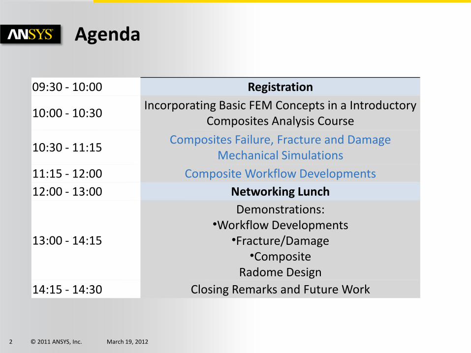
Agenda
09:30 - 10:00 Registration
10:00 - 10:30Incorporating Basic FEM Concepts in a Introductory
Composites Analysis Course
10:30 - 11:15Composites Failure, Fracture and Damage
Mechanical Simulations
11:15 - 12:00 Composite Workflow Developments
12:00 - 13:00 Networking Lunch
13:00 - 14:15
Demonstrations:•Workflow Developments
•Fracture/Damage•Composite
Radome Design
14:15 - 14:30 Closing Remarks and Future Work

© 2011 ANSYS, Inc. March 19, 20123
• Presenter: Sean Harvey
• Senior Technical Services Engineer
• Part of Aerospace and Defense Team
• Background in Composites, Non Linearity and Biomedical
• Composites is a very broad topic, and impossible to cover all aspects in this seminar
• Today’s focus is on laminated composites and the enhanced workflow at ANSYS R14
• Delamination, damage, and fracture will also be discussed.
Introduction

© 2011 ANSYS, Inc. March 19, 20124
Simulation-Driven Product Development
Democratize Simulation
Process Automation
Enable Best Practices
Focus on Engineering
Complete Systems
Simulated Environments
Multiphysics
Fluids Dynamics
Structural Mechanics
Explicit Dynamics
Low-Frequency Electromagnetics
High-Frequency Electromagnetics
Thermal Mechanics
Acoustics
Span Organizational and Geographic Silos
Share Engineering Insights
Better Decisions Faster
Our Strategy

© 2011 ANSYS, Inc. March 19, 20125
Composites in our World
Application Areas
• Aerospace
• Wind Energy
• Sports & Recreation
• Motorsport
• Construction
• Automotive
• Marine
• Defense
• Biomedical
• … and more

© 2011 ANSYS, Inc. March 19, 20126
Composite Progressive Damage and Fracture
What happens beyond first ply failure?
•Progressive Damage
How to model delamination and debonding?
•Cohesive Zone Model (CZM)•Virtual Crack Closure Technique (VCCT)
© 2011 ANSYS, Inc. March 19, 20127
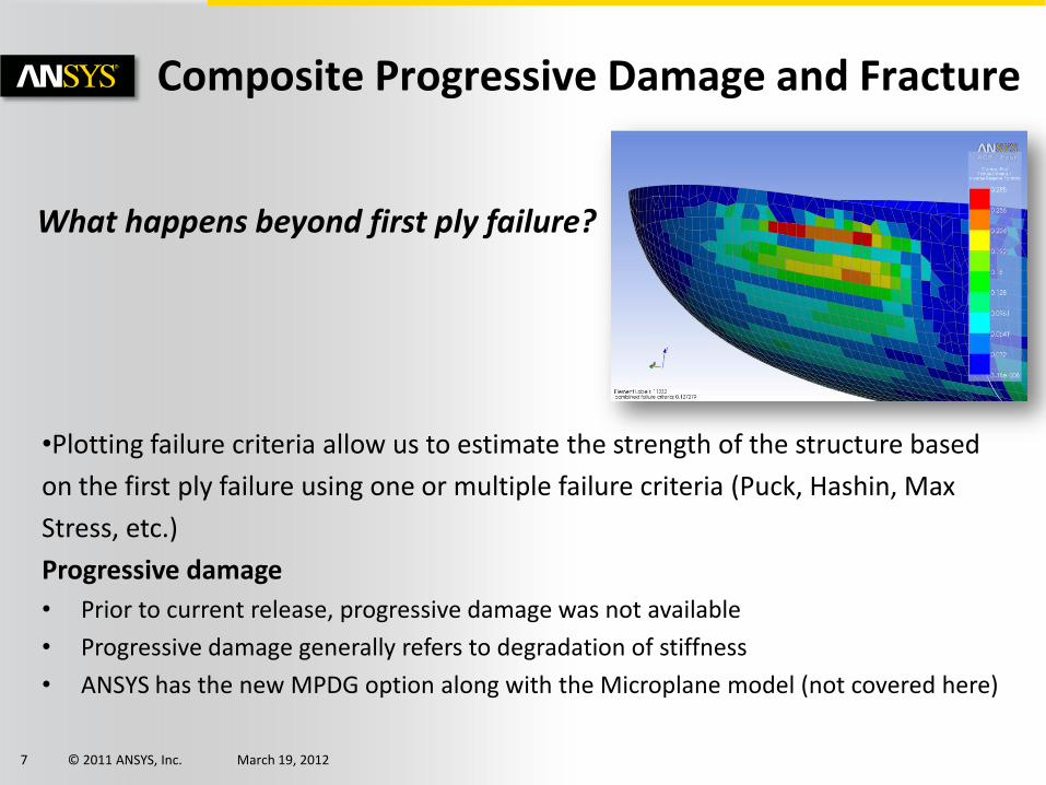
Composite Progressive Damage and Fracture
What happens beyond first ply failure?
•Plotting failure criteria allow us to estimate the strength of the structure based
on the first ply failure using one or multiple failure criteria (Puck, Hashin, Max
Stress, etc.)
Progressive damage
• Prior to current release, progressive damage was not available
• Progressive damage generally refers to degradation of stiffness
• ANSYS has the new MPDG option along with the Microplane model (not covered here)

© 2011 ANSYS, Inc. March 19, 20128
Composite Progressive Damage and Fracture
What happens beyond first ply failure?
Progressive Damage MPDG Model•The damage initiation and propagation in fiber-reinforced composites can be simulated with a nonlinear solution process. •The new capability allows you to estimate ultimate composite strength under complex stress states. •The difference between first ply failure and ultimate is very dependent on the layup and loading. For some layups, the difference can be just a few percent, while with others, it can be much greater
•Damage Initiation Criteria - This defines the criteria type for determining the onset of the material damage under loading. The available failure criteria are as follows: •Maximum strain, Maximum stress, Puck, Hashin, LaRc03, LaRc04, User-defined•Damage Evolution Law - This defines the way material degrades following the initiation of damage

© 2011 ANSYS, Inc. March 19, 20129
• Desire to correlate ANSYS R14 Damage capability TB,DMGI & TB,DMGE WITH published work of Camanho and Matthews to showcase the new ANSYS R14 capabilities to the Aerospace/Defense industry as well as other industries performing simulations and strength predictions of composite structures.
• Paper Title:
Progressive Damage
Journal of Composite Materials December 1999 33: 2248-2280,

© 2011 ANSYS, Inc. March 19, 201210
• In this work, the Authors have experimental Load/Disp curves of composite coupons of Pin Loaded Net Tension, Shear-Out, and Bearing failure modes.
• Authors are using Abaqus Explicit with reduced integration and hourglass control.
• Hashin Failure on [0/90/-45/45]2s laminate made of T300/914.
• Simulation model is solid with one element per ply.
• Net Tension Failure experimental and Abaqus results shown below.
Progressive Damage

© 2011 ANSYS, Inc. March 19, 201211
• ANSYS model built in Workbench Mechanical.
• Composite Setup in ACP.
• Failure and damage commands added manually to .dat file and solved.
• Layered composite SHELL181 with pin as rigid contact.
• Damage Evolution stiffness reduction per the cited paper
Progressive Damage
! Specify Hashin strength termsTB,FCLI,my_mat_num,1,20,1TBTEMP,71.6TBDATA,1,1439.,-1318.,98.,-125.,98.,-125.TBDATA,7,79.,79.,79.
! Specify damage initiation HashinTB,DMGI,my_mat_num,1,4,FCRTTBTEMP,71.6TBDATA,1,4,4,4,4
! Specify damage evolution Hashin
TB,DMGE,my_mat_num,1,4,MPDGTBTEMP,71.6TBDATA,1,.93,.86,.8,.6

© 2011 ANSYS, Inc. March 19, 201212
• Specimen held ALL DOF at left edge, and at pin.
• Specimen displaced 1.2mm on right edge.
• Coupon dimension specified in this case to generate net tension failure, with some local bearing failure.
• Pin Contact is Normal Lagrange
Progressive Damage
© 2011 ANSYS, Inc. March 19, 201213
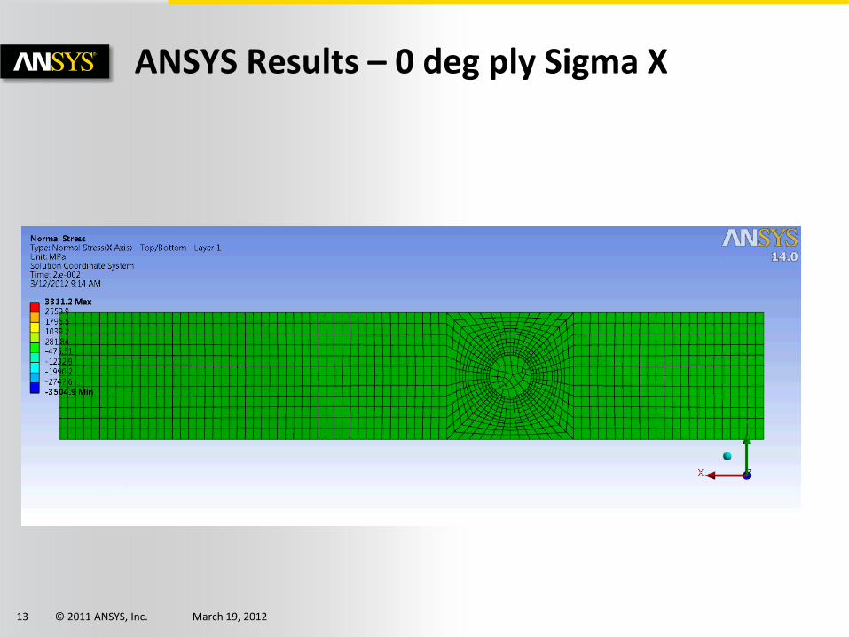
ANSYS Results – 0 deg ply Sigma X

© 2011 ANSYS, Inc. March 19, 201214
ANSYS Results – Damage Animation
© 2011 ANSYS, Inc. March 19, 201215
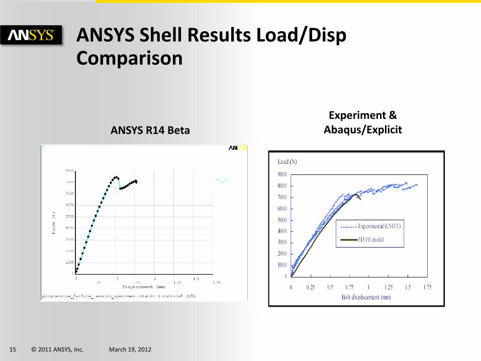
ANSYS Shell Results Load/DispComparison
ANSYS R14 Beta
Experiment & Abaqus/Explicit

© 2011 ANSYS, Inc. March 19, 201216
ANSYS Load Comparison
ANSYS R14 beta
Max Load (N)
Error (%)
-- --
8468 5.6
-- --
Abaqus

© 2011 ANSYS, Inc. March 19, 201217
Composite Progressive Damage and Fracture
How to model delamination and debonding?
Cohesive Zone Model - CZM is typically used to simulate:•Interface delamination of composite structures•Separation of adhesive joints •Fracture process in a homogenous medium
•This approach introduces failure mechanisms by using the hardening-softening relationships between the separations and incorporating the corresponding forces across the interface
•An interface delamination and failure simulation is performed by first separating the model into two components or groups of elements. A cohesive zone is then defined between these two groups. ANSYS offers two options to model the interface:•Interface elements with CZM model•Bonded Contact elements & CZM model
Interface Elements
© 2011 ANSYS, Inc. March 19, 201218
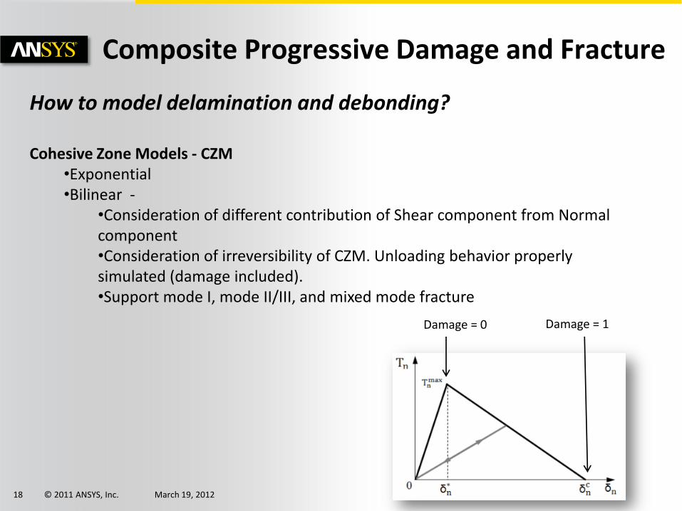
Composite Progressive Damage and Fracture
How to model delamination and debonding?
Cohesive Zone Models - CZM•Exponential•Bilinear -
•Consideration of different contribution of Shear component from Normal component•Consideration of irreversibility of CZM. Unloading behavior properly simulated (damage included).•Support mode I, mode II/III, and mixed mode fracture
Damage = 0 Damage = 1

© 2011 ANSYS, Inc. March 19, 201219
Composite Progressive Damage and Fracture
CZM Examples
Load Deflection CurveTwo bonded strips
© 2011 ANSYS, Inc. March 19, 201220
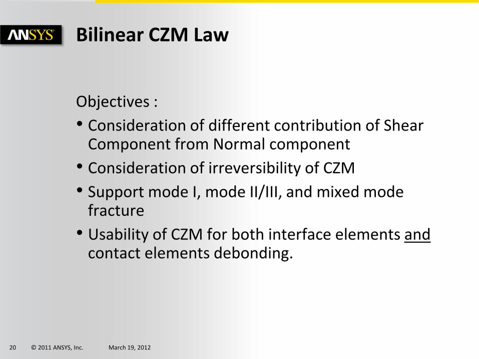
Bilinear CZM Law
Objectives :
• Consideration of different contribution of Shear Component from Normal component
• Consideration of irreversibility of CZM
• Support mode I, mode II/III, and mixed mode fracture
• Usability of CZM for both interface elements andcontact elements debonding.

© 2011 ANSYS, Inc. March 19, 201222
Bilinear Cohesive Zone Modeling using Contact
•The bilinear cohesive zone material is based on the model proposed by Alfano and Crisfield•Area Under the curve is the Normal Critical Fracture Energy Gcn (units Energy/Area)•Mode II/III Failure follows the same•Debonding is complete when this equation is satisfied
•Options to specifyCBDD -- Bilinear material behavior with linear softening characterized by maximum traction and maximum separation (valid for contact elements only). CBDE -- Bilinear material behavior with linear softening characterized by maximum traction and critical energy release rate (valid for contact elements only).
•User can specify normal, shear, or both

© 2011 ANSYS, Inc. March 19, 201223
Bilinear Cohesive Zone Modeling Example – Skin -Stringer
© 2011 ANSYS, Inc. March 19, 201224
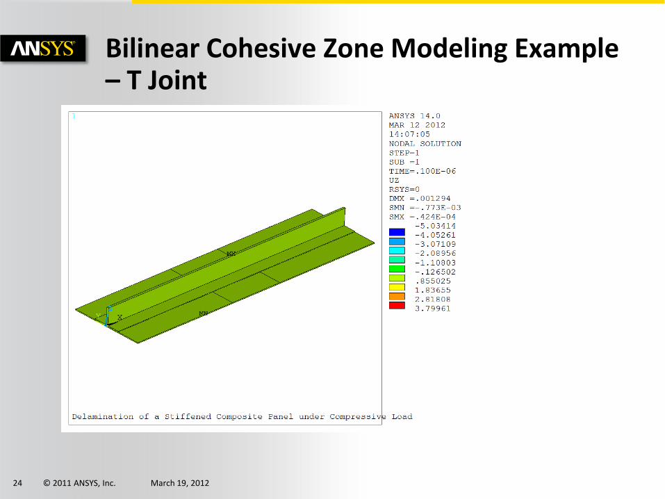
Bilinear Cohesive Zone Modeling Example – T Joint
© 2011 ANSYS, Inc. March 19, 201225
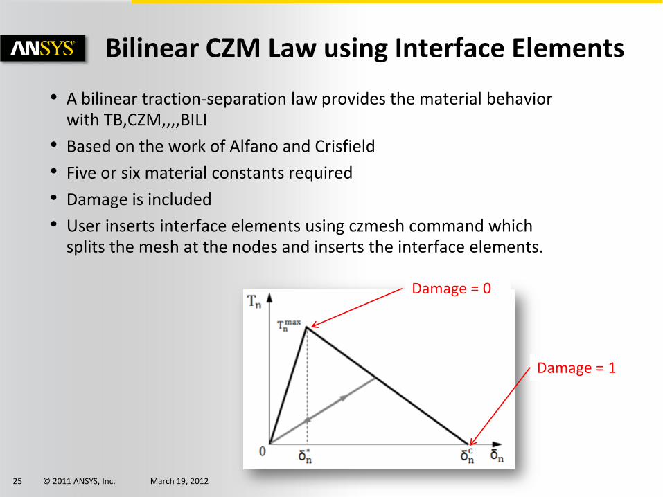
Bilinear CZM Law using Interface Elements
• A bilinear traction-separation law provides the material behavior with TB,CZM,,,,BILI
• Based on the work of Alfano and Crisfield
• Five or six material constants required
• Damage is included
• User inserts interface elements using czmesh command which splits the mesh at the nodes and inserts the interface elements.
Damage = 0
Damage = 1
© 2011 ANSYS, Inc. March 19, 201235
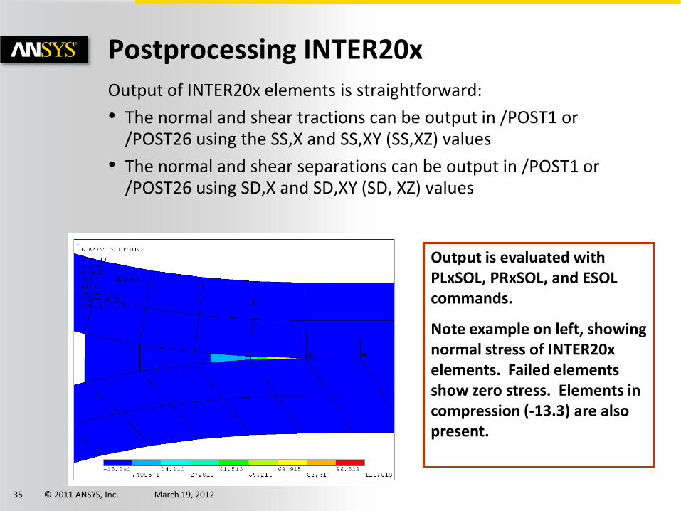
Postprocessing INTER20xOutput of INTER20x elements is straightforward:
• The normal and shear tractions can be output in /POST1 or /POST26 using the SS,X and SS,XY (SS,XZ) values
• The normal and shear separations can be output in /POST1 or /POST26 using SD,X and SD,XY (SD, XZ) values
Output is evaluated with PLxSOL, PRxSOL, and ESOL commands.
Note example on left, showing normal stress of INTER20x elements. Failed elements show zero stress. Elements in compression (-13.3) are also present.

© 2011 ANSYS, Inc. March 19, 201236
Composite Progressive Damage and Fracture
How to model delamination and debonding?
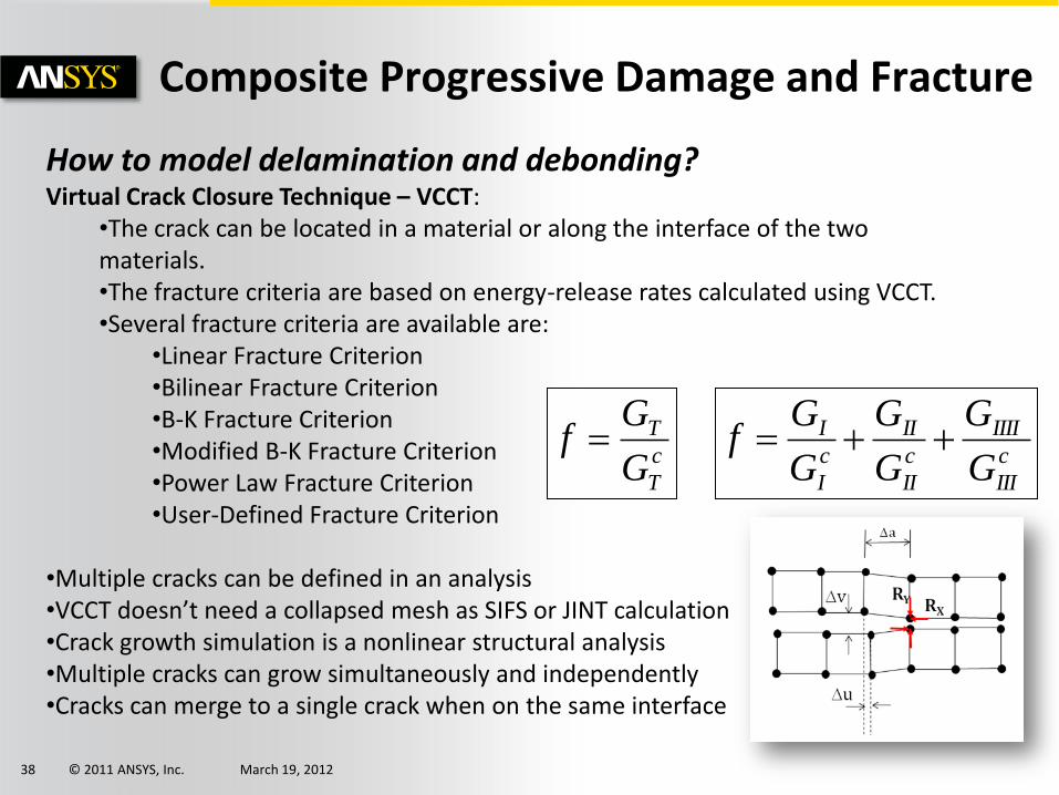
Virtual Crack Closure Technique – VCCT:
•Most commonly employed fracture mechanics approach to compute the debonding of composites structures•Based on the assumption that the energy needed to separate a surface is the same as the energy needed to close the same surface•VCCT was initially developed to calculate the energy-release rates of a cracked body and has been extended to crack propagation using interface elements•Crack growth occurs along a predefined crack path•The path is defined via interface elements.•The analysis is quasi-static and does not account for transient effects.•The material is linear elastic and can be isotropic, orthotropic or anisotropic.

© 2011 ANSYS, Inc. March 19, 201237
Composite Progressive Damage and Fracture
How is G (strain energy release rate) computed for 3D VCCT?
© 2011 ANSYS, Inc. March 19, 201238
Composite Progressive Damage and Fracture
How to model delamination and debonding?Virtual Crack Closure Technique – VCCT:
•The crack can be located in a material or along the interface of the two materials. •The fracture criteria are based on energy-release rates calculated using VCCT. •Several fracture criteria are available are:
•Linear Fracture Criterion •Bilinear Fracture Criterion •B-K Fracture Criterion •Modified B-K Fracture Criterion •Power Law Fracture Criterion •User-Defined Fracture Criterion
•Multiple cracks can be defined in an analysis•VCCT doesn’t need a collapsed mesh as SIFS or JINT calculation•Crack growth simulation is a nonlinear structural analysis•Multiple cracks can grow simultaneously and independently•Cracks can merge to a single crack when on the same interface
c
T
T
G
Gf
c
III
IIII
c
II
II
c
I
I
G
G
G
G
G
Gf

© 2011 ANSYS, Inc. March 19, 201239
VCCT-Based Crack Growth Simulation
ia
How to model delamination and debonding?Virtual Crack Closure Technique – VCCT:
•Fracture occurs when the fracture criterion index is met, expressed as
•In a crack growth simulation, a quantity of interest is the amount of crack extension. VCCT measures the crack extension based on the length of the interface elements that have opened, as expressed by the following equation and in the subsequent figure:
cff
© 2011 ANSYS, Inc. March 19, 201240
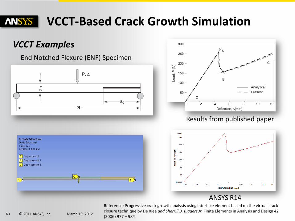
VCCT-Based Crack Growth Simulation
VCCT Examples
Results from published paper
ANSYS R14
End Notched Flexure (ENF) Specimen
Reference: Progressive crack growth analysis using interface element based on the virtual crack closure technique by De Xiea and Sherrill B. Biggers Jr. Finite Elements in Analysis and Design 42 (2006) 977 – 984
© 2011 ANSYS, Inc. March 19, 201241
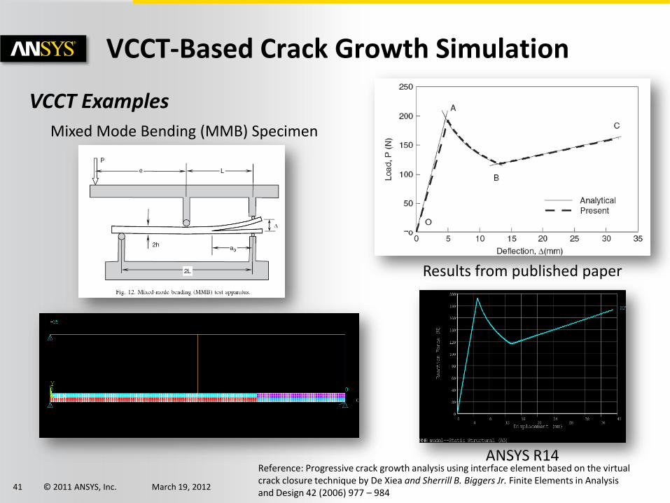
VCCT-Based Crack Growth Simulation
VCCT Examples
Results from published paper
ANSYS R14
Mixed Mode Bending (MMB) Specimen
Reference: Progressive crack growth analysis using interface element based on the virtual crack closure technique by De Xiea and Sherrill B. Biggers Jr. Finite Elements in Analysis and Design 42 (2006) 977 – 984

© 2011 ANSYS, Inc. March 19, 201242
VCCT-Based Crack Growth Simulation
VCCT Examples
Mixed Mode Bending (MMB) Specimen
Reference: Progressive crack growth analysis using interface element based on the virtual crack closure technique by De Xiea and Sherrill B. Biggers Jr. Finite Elements in Analysis and Design 42 (2006) 977 – 984
© 2011 ANSYS, Inc. March 19, 201243
Composite Workflow Developments

© 2011 ANSYS, Inc. March 19, 201244
Layered composites simulation requires:
• Orthotropic material stiffness terms (E’s, G’s, nu’s)
• Lamina (ply) thickness
• Fiber Orientation – draping
• Understanding of stacking sequence implications (ABD matrix coupling, bending and twisting during cure)
• Orthotropic strengths
• Understanding of numerous potential modes of failure and the various failure theories
Modeling Layered Composites Efficiently
What makes composites analysis challenging?

© 2011 ANSYS, Inc. March 19, 201245
Modeling Layered Composites Efficiently
Solid-ShellLayered Solid
Shell
Discrete/Smeared Reinforcement
ANSYS is not new to modeling composites:• Layered shell and solid elements for more than 2 decades
• Multi-material beams, with support for multiple layers and multiple section integrations
• Temp-Dep ortho material props with structural temps at each layer
• Composite PrepPost adds ease of use and results evaluation
• Integration into Workbench allows for rapid design studies
• VCCT and CZM, to characterize delamination and debonding for 7 years.
• Recent addition of progressive damage to characterize post first ply failure
Where does ANSYS stand with composite capabilities?

© 2011 ANSYS, Inc. March 19, 201246
Modeling Layered Composites Efficiently
What are some of the numerical approaches?
• Micro-Scale Approach – Detailed fiber matrix
interactions
• Meso-Scale (Laminate Level)
Approach – Layered Shells and Solids, extract
displacements, modes, overall stiffness behavior,
and detailed stresses and strains
• Macro-Scale Approach – Smeared or homogenous
shell/solid, with no detailed ply stresses nor strains

© 2011 ANSYS, Inc. March 19, 201247
Highlight several focus area for this discussion:
• Allow for geometric design changes to model
• Make changes to layup, ply locations, and orientations
• Incorporate fluid/thermal loading directly from CFD
• Incorporate loading from external data or other simulations
• Solve structural simulations all off the same unified model
• Static (linear & non-linear)
• Buckling (linear & non-linear)
• Transient Dynamic
• Linear Dynamics
• Explicit (Bird Strike, Drop Test, Crash and Impact, etc.)
• Ease of post-processing of composite results
Modeling Layered Composites Efficiently
What do we mean by Modeling Layered Composites Efficiently?
© 2011 ANSYS, Inc. March 19, 201248
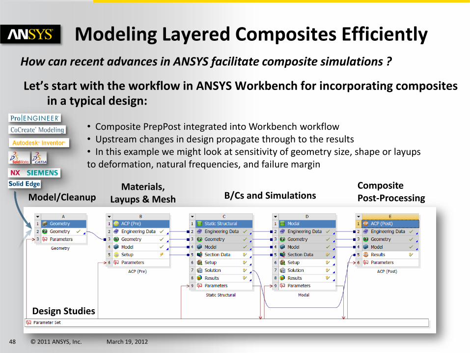
Let’s start with the workflow in ANSYS Workbench for incorporating composites in a typical design:
Modeling Layered Composites EfficientlyHow can recent advances in ANSYS facilitate composite simulations ?
Materials, Layups & Mesh B/Cs and Simulations
Composite Post-ProcessingModel/Cleanup
Design Studies
• Composite PrepPost integrated into Workbench workflow• Upstream changes in design propagate through to the results• In this example we might look at sensitivity of geometry size, shape or layups to deformation, natural frequencies, and failure margin

© 2011 ANSYS, Inc. March 19, 201249
Modeling Layered Composites Efficiently
Composites PrepPost is used to define the layup. Here we see the part thickness, cross-sections, and fiber orientations

© 2011 ANSYS, Inc. March 19, 201250
LayupMaterial Data
Fabrics/Stackups
Oriented
Element Sets
Layup Area
Layup Direction
Reference Direction
Modeling Layered Composites EfficientlyDefining the layup with PrepPost

© 2011 ANSYS, Inc. March 19, 201251
Modeling Layered Composites Efficiently
Make changes to layup, ply locations, orientationsHere we change the width of the doubler shown in red

© 2011 ANSYS, Inc. March 19, 201252
Modeling Layered Composites EfficientlyMake parametric changes to ply dimensions

© 2011 ANSYS, Inc. March 19, 201253
Modeling Layered Composites Efficiently
Fiber orientation prediction and modification
• Use internal draping calculations
• Interface with Vistagy’s FiberSim
• Modify the fiber orientation to something that is actually observed on the manufacturing floor.
• For this we use multiple rosettes (local coordinate systems) specifying the angle to match the measured at known locations, and let PrepPost interpolate in between.
Green – parallel to rosette, Blue– draped prediction
© 2011 ANSYS, Inc. March 19, 201254
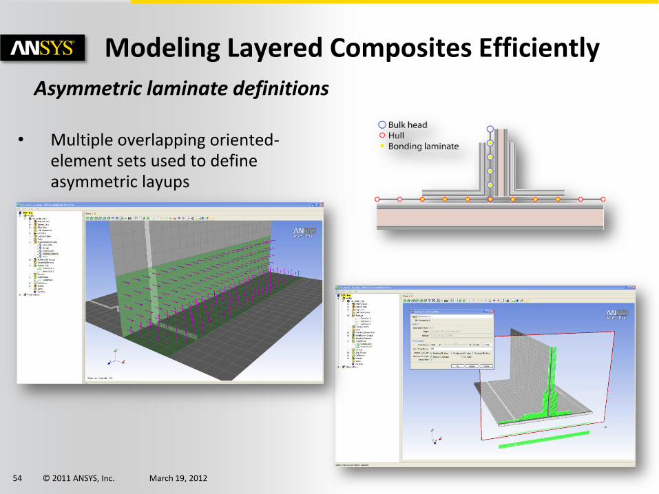
Modeling Layered Composites Efficiently
Asymmetric laminate definitions
• Multiple overlapping oriented-element sets used to define asymmetric layups
© 2011 ANSYS, Inc. March 19, 201255
Modeling Layered Composites Efficiently
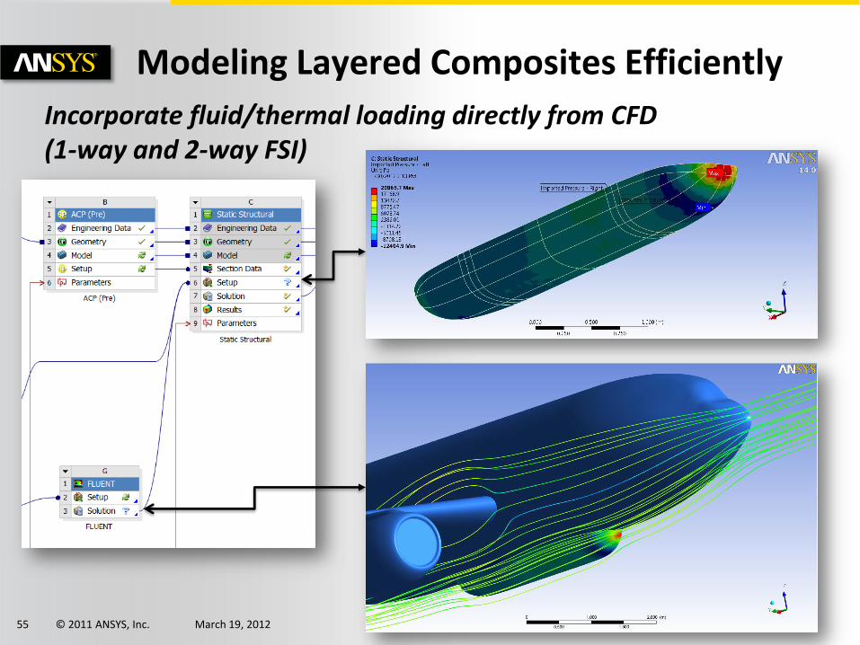
Incorporate fluid/thermal loading directly from CFD (1-way and 2-way FSI)

© 2011 ANSYS, Inc. March 19, 201256
Modeling Layered Composites Efficiently
Incorporate, transform, and validate loading from other simulations
Data Mapping•Pressure•Temperature•Heat Transfer•Thickness•Displacements

© 2011 ANSYS, Inc. March 19, 201257
Modeling Layered Composites Efficiently
Solve structural simulations all off the same unified modelPressure loading, modal, and non-linear buckling example

© 2011 ANSYS, Inc. March 19, 201258
Modeling Layered Composites Efficiently
Solve structural simulations all off the same unified modelPressure loading, modal, and tip load non-linear buckling
•Change spar chord location, wing taper, rib position, add stiffener plies to skin•Geometry, mesh, orientations, draping, properties, and results all updated
IRF - Distributed Pressure 2nd Natural Freq = 174 Hz IRF – 4” Tip Displacement
IRF - Distributed Pressure 2nd Natural Freq = 241 Hz IRF – 4” Tip Displacement

© 2011 ANSYS, Inc. March 19, 201259
Modeling Layered Composites Efficiently
Perform what-if studiesHere we look at how the tip deflection and 2nd natural frequency change with the 1st rib spanwise location.
Create response surfaces for optimization
© 2011 ANSYS, Inc. March 19, 201260
Modeling Layered Composites Efficiently
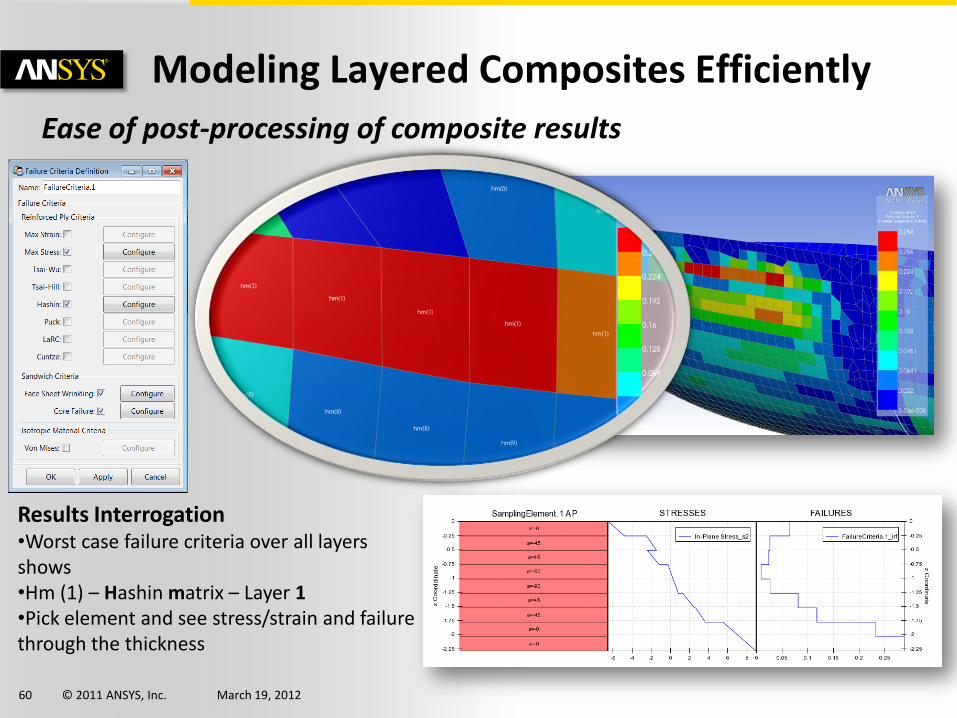
Ease of post-processing of composite results
Results Interrogation•Worst case failure criteria over all layers shows•Hm (1) – Hashin matrix – Layer 1•Pick element and see stress/strain and failure through the thickness

© 2011 ANSYS, Inc. March 19, 201261
Modeling Layered Composites Efficiently
Ease of post-processing of composite results
Thru-Thickness Stress Plots – Solids
Thru-Thickness Stress Plots – Shells
Make Thru-Thickness Stress Plots and account for Interlaminar normal stresses with shells•Below we look at the stress through the thickness in the bend•Traditional shell approaches can not account for interlaminar normal stress (shown in blue curve)•ANSYS Composite PrepPost can predict these base on the work of Roos, Kress & Ermanni•Make more accurate assessments without the need for large 3D models

© 2011 ANSYS, Inc. March 19, 201262
Modeling Layered Composites Efficiently
Ease of post-processing of composite results
Wrinkling
• Local buckling of a face sheet under compression
• Failure indicator available using shell modeling of sandwich
Core Failure
• Local failure of core in shear or tensile loading
• Failure indicator available using shell modeling of sandwich

© 2011 ANSYS, Inc. March 19, 201263
Modeling Layered Composites Efficiently
Even more..
•3D Models from shell models
•3D Curves used to guide fiber orientation
•Flat pattern prediction
•Right click suppress parts or plies
•Map composite thickness from 3D CAD
•Build complex assemblies including contact
•Include mechanisms
•Customize layups using scripts and tables
(Filament winding)
•2-Way FSI with composites

© 2011 ANSYS, Inc. March 19, 201264
Modeling Layered Composites Efficiently
Explicit dynamic model uses same composite setup
•Bird-Strike, Drop Test, Crash and Impact, etc.
•Simple setup for Eulerian mesh

© 2011 ANSYS, Inc. March 19, 201265
Modeling Layered Composites Efficiently
Radome Case Study
Connections
Deformations from FSI
Failure Criteria

© 2011 ANSYS, Inc. March 19, 201266
Modeling Layered Composites Efficiently
Radome Case Study – Bird Strike

© 2011 ANSYS, Inc. March 19, 201267
Beam Modeling – Advanced Capabilities
•User Defined Sections•Composite Sections•Tapering•Results (Disp, Strain, Stress) shown on Beam

© 2011 ANSYS, Inc. March 19, 201268
Features for upcoming release
• PrepPost parameters available in Workbench
• Layup definition as input parameters
• Failure criteria as output parameters
• Will allow for geometric and ply orientation design studies and even optimization
• Delamination/Interface layer defined as a named selection and automatically created in PrepPost when user picks solid model
• More integrated workflow for solid composites
• Fracture integrated into Mechanical
• XFEM at R15
• CDM based progressive damage
• Acoustic Simulation for Delamination Detection

© 2011 ANSYS, Inc. March 19, 201269
Summary
• Composites simulations with ANSYS
• Setup model one time, make changes to examine what if
• Look at sensitivities of design changes
• Investigate damage tolerance to flaws
• Investigate post first ply failure
• Simple “Drag-and-Drop” Multiphysics
• Easily incorporate thermal, fluids, and pressures
• Additional capability to import 3rd party data
• Improve design fidelity by optimization
• One single framework – ANSYS Workbench

© 2011 ANSYS, Inc. March 19, 201270
Thank You!
Recommended