Models AD1C51 AD2C51 AS1C51 AS2C51 AD1C5112 AD2C5112 AS1C5112 AS2C5112 AD1C71 AD2C71 AS1C71 AS2C71 AD1C7112 AD2C7112 AS1C7112 AS2C7112 AU1C7112 AU2C7112
Circle the model of your cooler and record the serial number below.
Read Carefully All Of This Manual Before Installing The Unit
Encierrre con un circulo el modelo de su enfriador y escribe el número de série abajo.
Lea Con Cuidado Todo Este Manual Antes De Instalar La Unidad
Serial #Número De Série
Safety Rules1. Read instructions carefully.2. Electrical hook up should be done by a qualifi ed electrician, so
that all electrical wiring will conform to your local standards.3. Always DISCONNECT POWER and UNPLUG motor and
pump inside the cooler before installing or performing any maintenance.
4. Motor and pump have a grounded, molded plug and an automatic thermal overload switch which will shut motor off when it overheats. The motor will restart automatically when it cools down.WARNING: To reduce the risk of fi re or electric shock, do not
use this fan with any “solid-state fan speed control device.”
Read And Save These Instructions
Vea el Español en el interior.
110498-3 5-07www.championcooler.com
Table Of Contents
Safety Instructions .......................................................................1Installation Instructions ............................................................ 2-3Electrical Wiring Diagram ...........................................................3Operation .................................................................................. 3-4Maintenance Section ....................................................................4Troubleshooting ...........................................................................5
Warranty .......................................................................................5Parts List (Down Discharge Units) .......................................... 6-7Parts List (Side Discharge Units) ............................................. 8-9Parts List (Up Discharge Units) ........................................... 10-11Specifi cation Tables (Tablas de Especifi caciones) .....................12Instrucciones en Español ..................................................... 12-16
Evaporative CoolingEvaporative cooling is nature’s way of cooling. When air is moved over a wet surface, water is evaporated and heat is absorbed. When stepping out of swimming pool with the wind blowing, evaporative cooling makes you feel cool, even though the air may be warm.
This unit works on the same principle. Air is drawn across wet fi lter pads where the air is cooled by evaporation and then circulated throughout the building. It is this combination of cooled air and the movement of air over the skin which makes it feel cool.
Unlike refrigeration systems which recirculate the air, an evaporative cooler continually brings in fresh air while exhausting old air. You are completely replacing the air every 2 to 4 minutes by opening windows or doors or a combination of both. The air is always fresh, not stale, laden with smoke and odors as happens with refrigerated air conditioning.
C O M P L E T E

2 110498-3
Cooler InstallationCAUTION: Make sure that the mounting surface is strong
enough to support the operating weight of the cooler when in use. (For operating weight, see Specifi cation Table.)
CAUTION: Never start cooler until installation is complete and unit has been tested for rigidity.
CAUTION: Do not screw or drill within 5 inches of the bottom of the wet module. You could puncture the reservoir.
NOTE: For ease of installation you can separate the wet module from the blower module by removing the 4 bolts from the wet module side (Fig. 1). Remember to unplug the pump and drain pump before separating the modules.
Water Connection• Install overfl ow assembly. Remove
nut and place nipple through the hole in the pan, with the rubber washer be-tween the pan and the head of the drain nipple (Fig. 2). Screw on nut and draw up tight against bottom of pan. Insert overfl ow into nipple to retain water. The overfl ow pipe comes from the fac-tory connected to the dump pump hose. The overfl ow pipe may be removed to drain pan when necessary. A garden hose may be screwed on the drain nipple to drain water away from your unit.
• Connect water supply line. Install a sillcock and water valve on faucet as shown by fi gure 3. Place the nut and ferrule on the tubing and tighten the nut until water tight. NOTE: Do not connect the water supply to any soft water applications.
• Install fl oat valve and fi ll pan. Refer to Fig. 4. Remove items 1, 2, 3, and 4. Insert fl oat body (5) through hole in back post panel as shown. Install washer (1) and nut (2). Tighten to keep fl oat from turn-ing. Place nut (4) and ferrule (3) on water supply line. Connect to fl oat fi tting and tighten until water tight. Bend rod (6) to adjust fl oat until water level is about 1 inch below the top of the overfl ow pipe. Slide fl oat shield (7) over fl oat body (5) until it snaps into place.
We recommend using a 20 Amp breaker for 120V supply or a 15Amp breaker for 230V supply. Note: Electrical installation should be performed by a qualifi ed electrician. Be sure to follow all National and Local Electrical Codes when installing this cooler.
• Install weatherproof switch box. Located inside the unit in a plastic bag is a switch box and cover, a chase nipple, a seal ring and a toggle switch. Remove the electrical junction box (Fig. 5) which is mounted on the inside of the center panel. From inside the unit, insert the chase nipple through the electrical access hole. Slide the seal ring over the chase nipple. Mount the switch box to the outside of the unit by threading the chase nip-ple into the switch box. Run the three switch leads through the nipple and into the switch box and reinstall the junction box. Connect the green ground lead to the ground screw in the switch box.
• Supply power to unit. Run power to the external switch box and connect to the two poles of the toggle switch. Connect the gray and white leads from the cooler electrical box to the two poles of the toggle switch. Refer to the appropriate wiring diagram to complete the electrical installation of your cooler. Secure the switch into the switch box and install the gasket and switch cover.
CAUTION: All openings in the external switch box must be sealed to prevent water from entering the switch box.
CAUTION: Pump receptacles are for grounded evaporative cooler pumps only. Do not plug anything else into receptacle.
WARNING: Make sure that cooler cabinet is properly grounded to a suitable ground connection for maximum safety.
Thermostat Installation1) Find a suitable location for the wall thermostat (away from sources
of heat, sunlight, or ventilation, and between 4 and 6 feet from the fl oor). The thermostat may be mounted to a standard electrical box.
2) Route an insulated four-conductor thermostat cable (or similar) from the Control Box inside the cooler to the thermostat electrical box. This cable is not supplied. WARNING: The thermostat cable should not be routed next to or enter the cabinet through the same inlet as the power supply wire.
3) Connect the thermostat wires to the terminals on the back of the wall control and to the terminals located on the left side of the control box in the unit. Make sure to follow the color code found next to each terminal.
Electrical InstallationWARNING: Disconnect all electrical service that will be used
for this unit before you begin the installation and leave it discon-nected until the installation is complete.
The control box is factory wired and installed for either 120V or 230V operation depending on the model you purchased. The supply power should be adequately protected against overloads and short circuits.
Amperage Draw And Belt TensionThis unit is equipped with an adjustable motor drive sheave for adjusting the blower wheel speed to the proper loading on different duct systems. It is important that the motor drive pulley is adjusted to correct size to assure maximum air delivery without damage to the motor. Be sure to follow these instructions carefully.
• Adjust drive pulley. After the unit is completely installed, adjust the drive pulley to the least diameter and adjust belt tension. See the maintenance section for adjusting belt tension.
• Start cooler. Install both inspection panels, start pump, and allow to operate until pads are wet.
Wet Module
Fig. 1
Mounting Bolts
Faucet
Wat
er S
uppl
y Va
lve
Sillcock
Ferr
ule
Nut
Fig. 3
12
34
5
6
7
Fig. 4
Rubber Washer
Overfl ow Pipe
Nipple
Bottom PanNut
Fig. 2
Drain Pump Hose
Fig. 5
ElectricalBox
Seal RingJunction
BoxChase Nipple

3110498-3
During automatic operation, the control performs a 90 second water dump cycle every 8 or 12 hours of pump operation. This interval can be toggled between 8 or 12 hours by simultaneously holding the ‘Cool’ and ‘Fan’ buttons for 5 seconds. The selected interval is displayed for a short time. This action also starts a manual dump cycle.
Ventilation Operation (Fan Mode)The fan speed is set by the user, the water pump is turned off.
This mode is activated by pressing the ‘Fan’ button. A green LED is illuminated, and the LCD indicates fan speed. Pressing the ‘Fan’ button again deselects this mode.
Pressing the ‘Up’ button selects maximum Fan speed, and ‘Hi’ is displayed in the LCD; pressing the ‘Down’ button selects minimum Fan speed, and ‘Lo’ is displayed in the LCD.
Time Delay Operation (Timer Mode)Delayed start or fi nish in ‘Cool’ or ‘Fan’ mode.
The ‘Timer’ button is used to set a delay period of 2, 4 or 8 hours, depending on how many times the button is pressed.
If the cooler is operating in ‘Cool’ or ‘Fan’ modes when the ‘Timer’ button is pressed, the delay period determines when the cooler will switch off. If the cooler is Off when the ‘Timer’ button is pressed, the delay period determines when the cooler switches on.
The starting mode is indicated by a fl ashing LED. You can change this mode by pressing the appropriate button (‘Cool’ or ‘Fan’).
You can cancel the Timer function at any time by pressing the ‘Timer’ button until all the timer LED’s go out.
In The Event Of A Power OutageIf the cooler is operating in ‘Cool’ or ‘Fan’ mode when power is interrupted, the cooler will resume in the same mode of operation when the power is restored.
If the cooler was in any ‘Timer’ mode at the time of a power interruption, the cooler will remain off when power is restored.
Wiring Diagrams
Thermostat OperationAutomatic Operation (Cool Mode)The fan and water pump are controlled automatically to achieve the desired comfort level.
This mode is activated by pressing the ‘Cool’ button. A blue LED is illuminated, and for a few seconds the LCD will display the ‘Set’ temperature. Pressing the ‘Cool’ button again deactivates this mode.
The Set temperature (the target temperature for control) may be altered by repeatedly pressing or holding the ‘Up’ and ‘Down’ buttons. The LCD will display ‘Set’ rather than ‘Room’ temperature for a short time after pressing the ‘Up’ or ‘Down’ button.
On starting, if the pads in the cooler are too dry, the fan may be delayed from starting until the pads have absorbed some water. This is called Pre-wet and lasts for 2 minutes, indicated by a fl ashing blue LED. Selecting ‘Fan’ and then ‘Cool’ will bypass the pre-wet and cause the fan and pump to start immediately. (If cooling is required).
• Check amperage. With pads wet and unit started, check amperage draw with an amperage meter.
• Adjust pulley if necessary. If amperage draw is less than motor rating, turn off electrical power and remove inspection panels. Unplug motor inside cooler, this will protect you from someone turning on unit while you are working inside. This should be done for your safety. Adjust pulley to a larger diameter and readjust belt tension, plug motor in, install inspection panels, and retest amperage draw. Repeat this process until correct amperage draw is at-tained. Increasing motor pulley diameter increases amperage draw. Decreasing motor pulley diameter decreases amper-age draw (see Fig. 6).CAUTION: Do not operate cooler with larger amperage draw
than specifi ed on motor plate.
120 Volt 240 Volt
Decrease Amperage
Fig. 6
FAN MOTOR
THERMOSTAT
RECEPTACLE
RECEPTACLECIRCULATING PUMP
RECEPTACLEDRAIN PUMP
120 VAC
WHITE
RED
COOLER TERMINAL BOX
WHITEGREEN
BLACK
GREENWHITEBLUE
=WIRE NUT
SWITCH LEADS
VIOLETBLUE
YELLOW
GRAYBLACK
RED
GREENWHITEGRAY
GROUND
TOGGLE SWITCH
(11)
FLoFH
iFC
om
LINK L1 N
NLink
PP
PC
om DP
DC
om
DUMPPUMPFAN PWR. SUPPLY
ORANGE
ORANGEBROWN
BROWNORANGE
BLUEWHITEGREEN
SWITCH LEADS
=WIRE NUT
WHITEGREEN
BLACK
GREENWHITE
COOLER TERMINAL BOX
RED
BLUE
GREENWHITEBLUE
ORANGEBROWN
BROWNORANGE
ORANGE
WHITE
240 VAC
DRAIN PUMPRECEPTACLE
CIRCULATING PUMPRECEPTACLE
RECEPTACLE
THERMOSTAT
FAN MOTOR
PWR. SUPPLYFAN PUMP DUMP
DC
omDP
PC
omPP
NLinkNL1
LINK
FComFH
iFLo
(11)
TOGGLE SWITCH
GROUND
GRAYWHITEGREEN
REDBLACKGRAY
YELLOWBLUE
VIOLET

4 110498-3
MaintenanceWARNING : Before doing any maintenance be sure power
is off. At the time you remove either inspection panel be sure to unplug motor and pumps. This is for your safety.
Spring Start-Up• Clean pads. A clean pad is more absorbent, effi cient and will give
more cool air. Annually, or when required, using a garden hose with nozzle, back wash to clean out the openings, then clean off the inlet face any scale or other obstruction to the passages. Slight scraping may be required to remove hardened scale.
• Change pads if necessary. The pads should be replaced after 5 years or if necessary. To change pads, remove top access panel, remove grill, and disconnect water delivery tube. Remove water distributor holder and lift out media sections. Replace with the same type media. You can purchase them from your dealer.
IMPORTANT: In order to get the best performance from your cooling pads, they must be installed properly. If you have pur-chased a pad with two equal angles, the following instructions can be disregarded. Pads must always be installed with the steeper fl ute angle sloping down towards the air entering side (Fig. 7). The reason is simple. The steeper angle puts more water on the hot, dry, dirty side of the pad where it is needed most. It also counteracts the tendency of the air to push the water toward the back of the pad.
• Check belt tension. A 3 lb. force
should defl ect the belt 3/4 inches (see Fig. 8). Readjust belt if needed.
• Oil bearings. The blower bearings and cooler motor in this unit should be oiled with a few drops of non-detergent 20/30 weight oil once each year. The motor does not need oil if it has no oil lines for oiling. Motors that have no oil lines are lifetime oiled at the factory and require no further oiling for the life of the unit.CAUTION: Do not over oil. Over oiling can cause motor burn
out, due to excessive oil getting into motor winding.
• Clean water pump and dump pump. Cleaning both pumps is necessary once a year at start-up. For your safety, turn unit off and unplug motor and pumps. Remove the pump from the mount slot. Remove the base of the pump as shown in Fig. 9. Clean the pump and turn the impeller to ensure free operation. Remove the pump spout and check for any blockage. After cleaning, reinstall the base onto the pump. Press fi rmly to make sure it is secure. Reattach the pump to the mount in the cooler using the plastic retainer to ensure that the pump will not overturn. Do not forget to replace the spout and water delivery tube onto the pump outlet.
Winter Shut-Down• Drain water. Always drain all of the water out of the cooler and
water supply line when not in use for prolonged periods, and par-ticularly at the end of the season. Keep the water line disconnected from both the unit and water supply so that it does not freeze.
• Unplug motor and pumps. When cooler is not used for extended periods unplug the motor and pumps from inside cooler.
• Cover unit. To protect the life of the fi nish, a cover for the unit is suggested in extended periods of non use.
By following the operating, installation, and maintenance suggestions as outlined, you can get many years of efficient and satisfactory service from your cooler. In the event additional information is desired, your dealer will be more than glad to assist you in every possible way.
Required Exhaust OpeningsAn often misunderstood concept of evaporative cooling is the amount of air that should be exhausted. How much should you open your windows? The fact is that most people do not open their windows enough. The following two methods will help you determine the amount to open your windows.
First MethodYou should allow an opening of at least 2 square feet (288 square inches) for each 1000 CFM rating of your unit. Example: At 3790 CFM, model AD1C51 (3/4 hp) requires 7.6 square feet (1094 square inches) of opening (3790/1000 * 2 = 7.6). Multiply the number of windows by window width in inches and divide this into the number of square inches required for your size unit. This will give you the height to open windows. In this example, four 36 inch wide windows should be opened 7.6 inches each.
Champion Air Balancing Method1. Take a piece of tissue paper and cut it lengthwise into 3 equal
strips.2. Turn your cooler on high cool.3. Open one window at least six inches wide in each room that you
want to cool.4. Take the piece of tissue paper and put it up against the screen of
the open window furthest from the cooler discharge opening. Let go of it. It will do one of three things.
IF It falls down.THEN CLOSE all of the windows one inch and try step 4 again.
IF It plasters itself to the screen.THEN OPEN all of the windows one inch and try step 4 again.
IF It stays on the screen lightly.THEN PERFECT. You are done. Enjoy your cooler.
NOTES:• When switching to low cool, you must rebalance your home. Repeat
step 4.• Once you balance your home you can cool some areas more than
others by opening those windows more and closing the others by the same amount. Repeat step 4 to make sure your home is still air balanced.
45°
15°
Entering Air Leaving Air
Fig. 7
Fig. 8
3 Lb.3/4 Inches
Impeller
RemoveBase
Fig. 9

5110498-3
Limited WarrantyThis warranty is extended to the original purchaser of an evaporative cooler installed and used under normal conditions. It does not cover damages in-curred through accident, neglect, or abuse by the owner. We do not authorize any person or representative to assume for us any other or different liability in connection with this product.
Terms And Conditions Of WarrantyLifetime Limited Coverage on water reservoir against any leakage due to defects in material. From date of purchase, if any original component part provided by Champion Cooler fails due to defect in material or factory workmanship only, we will provide the replacement part as follows:
One year on the cabinet components. Five years on the evaporative media. Two years on the original blower motor if furnished by Champion Cooler.
Exclusions From The WarrantyWe are not responsible for any incidental or consequential damage resulting from any malfunction.
We are not responsible for any damage received from the use of water softeners, chemicals, descale material, plastic wrap, or if a motor of a higher horsepower than what is shown on the serial plate is used in the unit.
We are not responsible for the cost of service calls to diagnose cause of trouble, or labor charge to repair and/or replace parts.
How To Obtain Service Under This WarrantyContact the Dealer where you purchased the evaporative cooler. If for any reason you are not satisfi ed with the response from the dealer, contact the Customer Service Department: Champion Cooler, 5800 Murray Street, Little Rock, Arkansas 72209. 1-800-643-8341. E-mail: [email protected].
This limited warranty applies to original purchaser only.
Problem Possible Cause RemedyFailure to start or no air delivery/ No LCD display
Inadequate air delivery with cooler running
1. No electrical power to unit
• Fuse blown • Circuit breaker tripped2. Motor overheated • Belt too tight • Blower bearings dry • Motor pulley diameter
too large3. Motor locked4. Fuse blown in unit
control box5. Incorrect wiring be-
tween wall thermostat and cooler
6. Poor connection to Fan motor terminals
7. Unit control board or wall thermostat faulty
1. Insuffi cient air exhaust
2. Belt too loose
3. Pads plugged4. Motor underloaded
1. Check power
• Replace fuse • Re-set breaker2. Determine cause • Adjust belt tension • Oil blower bearings • Adjust pulley to correct
diameter3. Replace motor4. Replace Fuse
5. Check that wiring is correct and secured to terminals
6. Check connections to termi-nal
7. Supply power to control box and check DC voltage at wall thermostat
• If voltage between Black & Red terminals is close to 3.5VDC and LCD is blank - wall thermostat is faulty
• If voltage is much less than 3.5VDC, remove red wire from terminal. If voltage rises to 3.5VDC - thermostat is faulty. If voltage remains low - unit control board is faulty.
1. Open windows or doors to increase air fl ow
2. Adjust belt tension or replace if needed
3. Clean pads4. Adjust pulley
Troubleshooting Guide
Problem Possible Cause Remedy1. Float arm not adjusted
properly2. Overfl ow assembly
leaking
1. Stale or stagnate water in cooler
1. Low voltage2. Excessive belt tension3. Blower shaft tight or
locked4. Bearings dry5. Motor pulley diameter
too large causing motor overload
1. Bearings dry2. Wheel rubbing blower
housing3. Loose parts
1. Inadequate exhaust in house
2. Pads not wet
• Pads plugged • Dist. tube holes clogged • Pump not working prop-
erly3. Poor connection to Pump
terminals on Control Board
1. Insuffi cient air exhaust
1. Adjust fl oat
2. Tighten nut and overfl ow pipe
1. Drain pan and clean pads
1. Check voltage2. Adjust belt tension3. Oil or replace bearings
(Unplug unit)4. Oil bearings5. Adjust pulley so full load
ampere rating of motor is not exceeded
1. Oil bearings2. Inspect and realign (Un-
plug unit)3. Tighten loose parts
1. Open windows or doors to increase air fl ow
2. Check water distribution system
• Clean pads • Clean • Replace or clean pump
(Unplug unit)3. Check connections
1. Open doors or windows
Water drain-ing onto roof
Musty or unpleasant odor
Motor cycles on and off
Noisy
Inadequate cooling
Excessive humidity in house
Register your product online at www.championcooler.com/eac/onlineregistration-eac.htm

6 110498-3
No. AD1C51 AD1C5112 AD1C71 AD1C7112N° Description / Descripción AD2C51 AD2C5112 AD2C71 AD2C71121. Top, Cabinet / Tapa De La Caja ................................................................................222130-070 222130-070 222140-053 222140-0532. Top Access Panel / Panel Superior De Acceso ...........................................................222130-074 222130-075 222130-074 222130-0753. Bottom, Blower Section / Base De La Sección De La Rueda ....................................322130-068 322130-068 322140-051 322140-0514. Bottom, Wet Module / Base De La Sección De Agua ................................................222130-072 222130-073 222130-072 222130-0735. Front Panel / Panel Del Frente ...................................................................................222130-076 222130-076 222140-055 222140-0556. Inspection Panel / Panel De Inspección .....................................................................224130-002 224130-002 224140-002 224140-0027. Center Post, Right / Poste Central, Derecho ..............................................................222130-062 222130-062 222140-045 222140-0458. Center Post, Left / Poste Central, Izquierdo ...............................................................222130-063 222130-063 222140-046 222140-0469. Back Post, Right / Poste Trasero, Derecho ................................................................222130-064 222130-066 222140-047 222140-04910. Back Post, Left / Poste Trasero, Izquierdo .................................................................222130-065 222130-067 222140-048 222140-05011. Blower Housing / Caja De La Rueda .........................................................................324130-202 324130-202 324140-202 324140-20212. Cut-Off Plate / Placa Externa .....................................................................................224003-015 224003-015 224004-003 224004-00313. Blower Housing Supports / Soporte Para La Caja De La Rueda ..............................218001-034 218001-034 218001-037 218001-03714. Grill / Parrilla .............................................................................................................222130-078 222130-078 222140-057 222140-05715. Electrical Junction Box / Caja De Empalme ..............................................................322009-001 322009-001 322009-001 322009-00116. Motor Mount / Montura Del Motor ............................................................................314003-011 314003-011 314003-012 314003-01217. Motor Mount Clips / Seguros Para Montar Motor ....................................................314005-001 314005-001 314005-001 314005-00118. Motor / Motor .............................................................................................................* * * *19. Pulley, Motor / Polea Del Motor ................................................................................110279-004 110279-004 110279-003 110279-00320. Electrical Cord, Motor (115V) / Cable Eléctrico Del Motor (115V) ..........................110372 110372 110372 11037220. Electrical Cord, Motor (230V) / Cable Eléctrico Del Motor (230V) .........................110372-2 110372-2 110372-2 110372-221. Shaft, Blower Wheel / Eje De La Rueda ....................................................................110183 110183 110183 11018322. Blower Wheel / Rueda ................................................................................................16BW 16BW 20BW 20BW23. Pulley, Blower Wheel / Polea De La Rueda ...............................................................110275 110275 110276 11027624. Drive Belt / Correa .....................................................................................................110229 110229 110230 11023025. Bearings, Blower Wheel Shaft / Cojinetes Del Eje De La Rueda ..............................110351 110351 110351 11035126. Receptacle, Motor / Toma De Corriente Del Motor ...................................................110393 110393 110393 11039327. Receptacle, Pump / Toma De Corriente De La Bomba ..............................................110361 110361 110361 11036128. Media Shield Right / Protector Para El Medio Evaporativo, Direcho ......................281043-002 281045-002 281044-002 281046-00229. Media Shield Left / Protector Para El Medio Evaporativo, Izquierdo ......................281043-001 281045-001 281044-001 281046-00130. Water Distributor Housing / Caja Del Distribuidor De Agua ....................................281038-001 281033-001 281038-001 281033-00131. Water Distributor Tube / Tubo Del Distribuidor De Agua .........................................3D-23 3D-23 3D-23 3D-2332. Evaporative Media / Medio Evaporativo ....................................................................310117-001 310118-001 310117-002 310118-00233. Distributor Filter Pad / Filtro Del Distribuidor ..........................................................110120 110120 110120 11012034. Water Reservoir / Bandeja Acumuladora De Agua ....................................................281041 281042 281041 28104235. Tube, Water Delivery / Tubo De Agua ........................................................................310716 310716 310716 31071636. Over Flow Assembly / Montaje De Desagüe .............................................................310571-2 310571-2 310571-2 310571-237. Float Valve / Flotador .................................................................................................FL-C FL-C FL-C FL-C38. Float Shield / Salpicadero Del Flotador .....................................................................281006 281006 281006 28100639. Pump / Bomba.............................................................................................................** ** ** **40. Pump Screen / Malla Para La Bomba ........................................................................281001-001 281001-001 281001-001 281001-00141. Pump Mount / Montura De La Bomba .......................................................................218002-012 218002-012 218002-012 218002-01242. Pump Retainer / Sujetador De La Bomba...................................................................110714 110714 110714 11071443. Anti-Flattening Coil / Espiral Protectora ...................................................................110847 110847 110847 11084744. Dump Pump Bracket / Bomba ....................................................................................220101-011 220101-011 220101-011 220101-01145. Thermostat Mounting Bracket / Soporte Del Termostato ...........................................220101-010 220101-010 220101-010 220101-01046. T’Stat Thermostat Controls / Controles De Termostato .............................................110423 110423 110423 11042347. Switch Box / Caja De Interuptor................................................................................110821 110821 110821 11082148. Toggle Switch / Interuptor De Palanca ......................................................................110419 110419 110419 11041949. Switchbox Cover & Gasket / Cubierta y Junta De La Caja Del Interruptor .............110821-1 110821-1 110821-1 110821-150. Liquidtight Conduit / Conduit Flexible ......................................................................110816 110816 110816 11081651. Liquidtight Connectors / Conectores Para Conduit Flexible .....................................110817 110817 110817 11081752. Chase Nipple / Niple Roscado ....................................................................................110812 110812 110812 110812
* See the motor specifi cation table on page 12. / Vea la tabla de especifi caciones del motor en la página 12.** Pump for 115V units - #110436, Pump for 230V units - #C60P-240 / Bomba de 115V - #110436, Bomba de 230V - #C60P-240NOTE: Standard hardware items may be purchased from your local hardware store.NOTA: Artículos de uso corriente pueden comprarse en la ferretería de su localidad.
Replacement Parts List / Lista De Piezas De RepuestoWhen ordering parts, please be sure to furnish the following information on all orders. Failure to do so may delay your order. /Al pedir piezas, incluya toda la información siquiente con su pedido. El no proporcionar toda esta información resultará en una demora.
1. Cooler model number / El modelo de su enfriador 2. Cooler serial number / Número de serie de la unidad 3. Description and part number / Descripción y número de pieza 4. Date of purchase / Fecha de compra

7110498-3
Replacement Parts / Piezas De Repuesto
AD1C51, AD2C51, AD1C5112, AD2C5112, AD1C71, AD2C71, AD1C7112, AD2C7112

8 110498-3
No. AS1C51 AS1C5112 AS1C71 AS1C7112N° Description / Descripción AS2C51 AS2C5112 AS2C71 AS2C71121. Top, Cabinet / Tapa De La Caja ................................................................................222130-070 222130-070 222140-053 222140-0532. Top Access Panel / Panel Superior De Acceso ...........................................................222130-074 222130-075 222130-074 222130-0753. Bottom, Blower Section / Base De La Sección De La Rueda ....................................222130-069 222130-069 222140-052 222140-0524. Bottom, Wet Module / Base De La Sección De Agua ................................................222130-072 222130-073 222130-072 222130-0735. Front Panel / Panel Del Frente ...................................................................................322130-077 322130-077 322140-056 322140-0566. Inspection Panel / Panel De Inspección .....................................................................224130-002 224130-002 224140-002 224140-0027. Center Post, Right / Poste Central, Derecho ..............................................................222130-062 222130-062 222140-045 222140-0458. Center Post, Left / Poste Central, Izquierdo ...............................................................222130-063 222130-063 222140-046 222140-0469. Back Post, Right / Poste Trasero, Derecho ................................................................222130-064 222130-066 222140-047 222140-04910. Back Post, Left / Poste Trasero, Izquierdo .................................................................222130-065 222130-067 222140-048 222140-05011. Blower Housing / Caja De La Rueda .........................................................................324130-203 324130-203 324140-203 324140-20312. Cut-Off Plate / Placa Externa .....................................................................................224003-015 224003-015 224004-003 224004-00313a. Blower Housing Support, Right / Soporte Para La Caja De La Rueda, Derecho .....218001-035 218001-035 218001-038 218002-03813b. Blower Housing Support, Left / Soporte Para La Caja De La Rueda, Izquierdo ......218001-036 218001-036 218001-038 218002-03814. Grill / Parrilla .............................................................................................................222130-078 222130-078 222140-057 222140-05715. Electrical Junction Box / Caja De Empalme ..............................................................322009-001 322009-001 322009-001 322009-00116. Motor Mount / Montura Del Motor ............................................................................314003-011 314003-011 314003-012 314003-01217. Motor Mount Clips / Seguros Para Montar Motor ....................................................314005-001 314005-001 314005-001 314005-00118. Motor / Motor .............................................................................................................* * * *19. Pulley, Motor / Polea Del Motor ................................................................................110279-004 110279-004 110279-003 110279-00320. Electrical Cord, Motor (115V) / Cable Eléctrico Del Motor (115V) ..........................110372 110372 110372 11037220. Electrical Cord, Motor (230V) / Cable Eléctrico Del Motor (230V) .........................110372-2 110372-2 110372-2 110372-221. Shaft, Blower Wheel / Eje De La Rueda ....................................................................110183 110183 110183 11018322. Blower Wheel / Rueda ................................................................................................16BW 16BW 20BW 20BW23. Pulley, Blower Wheel / Polea De La Rueda ...............................................................110275 110275 110276 11027624. Drive Belt / Correa .....................................................................................................110212 110212 110213 11021325. Bearings, Blower Wheel Shaft / Cojinetes Del Eje De La Rueda ..............................110351 110351 110351 11035126. Receptacle, Motor / Toma De Corriente Del Motor ...................................................110393 110393 110393 11039327. Receptacle, Pump / Toma De Corriente De La Bomba ..............................................110361 110361 110361 11036128. Media Shield, Right / Protector Para El Medio Evaporativo, Direcho .....................281043-002 281045-002 281044-002 281046-00229. Media Shield, Left / Protector Para El Medio Evaporativo, Izquierdo .....................281043-001 281045-001 281044-001 281046-00130. Water Distributor Housing / Caja Del Distribuidor De Agua ....................................281038-001 281033-001 281038-001 281033-00131. Water Distributor Tube / Tubo Del Distribuidor De Agua .........................................3D-23 3D-23 3D-23 3D-2332. Evaporative Media / Medio Evaporativo ....................................................................310117-001 310118-001 310117-002 310118-00233. Distributor Filter Pad / Filtro Del Distribuidor ..........................................................110120 110120 110120 11012034. Water Reservoir / Bandeja Acumuladora De Agua ....................................................281041 281042 281041 28104235. Tube, Water Delivery / Tubo De Agua ........................................................................310716 310716 310716 31071636. Over Flow Assembly / Montaje De Desagüe .............................................................310571-2 310571-2 310571-2 310571-237. Float Valve / Flotador .................................................................................................FL-C FL-C FL-C FL-C38. Float Shield / Salpicadero Del Flotador .....................................................................281006 281006 281006 28100639. Pump Assembly / Bomba ............................................................................................** ** ** **40. Pump Screen / Malla Para La Bomba ........................................................................281001-001 281001-001 281001-001 281001-00141. Pump Mount / Montura De La Bomba .......................................................................218002-012 218002-012 218002-012 218002-01242. Pump Retainer / Sujetador De La Bomba...................................................................110714 110714 110714 11071443. Anti-Flattening Coil / Espiral Protectora ...................................................................110847 110847 110847 11084744. Dump Pump Bracket / Bomba ....................................................................................220101-011 220101-011 220101-011 220101-01145. Thermostat Mounting Bracket / Soporte Del Termostato ...........................................220101-010 220101-010 220101-010 220101-01046. T’Stat Thermostat Controls / Controles De Termostato .............................................110423 110423 110423 11042347. Switch Box / Caja De Interuptor................................................................................110821 110821 110821 11082148. Toggle Switch / Interuptor De Palanca ......................................................................110419 110419 110419 11041949. Switchbox Cover & Gasket / Cuberta y Junta De La Caja Del Interruptor ..............110821-1 110821-1 110821-1 110821-150. Liquidtight Conduit / Conduit Flexible ......................................................................110816 110816 110816 11081651. Liquidtight Connectors / Conectores Del Conduit Flexible .......................................110817 110817 110817 11081752. Chase Nipple / Niple Roscado ....................................................................................110812 110812 110812 110812
* See the motor specifi cation table on page 12. / Vea la tabla de especifi caciones del motor en la página 12.** Pump for 115V units - #110436, Pump for 230V units - #C60P-240 / Bomba de 115V - #110436, Bomba de 230V - #C60P-240NOTE: Standard hardware items may be purchased from your local hardware store.NOTA: Artículos de uso corriente pueden comprarse en la ferretería de su localidad.
Replacement Parts List / Lista De Piezas De RepuestoWhen ordering parts, please be sure to furnish the following information on all orders. Failure to do so may delay your order. /Al pedir piezas, incluya toda la información siquiente con su pedido. El no proporcionar toda esta información resultará en una demora.
1. Cooler model number / El modelo de su enfriador 2. Cooler serial number / Número de serie de la unidad 3. Description and part number / Descripción y número de pieza 4. Date of purchase / Fecha de compra

9110498-3
Replacement Parts / Piezas De Repuesto
AS1C51, AS2C51, AS1C5112, AS2C5112 AS1C71, AS2C71, AS1C7112, AS2C7112
10 110498-3
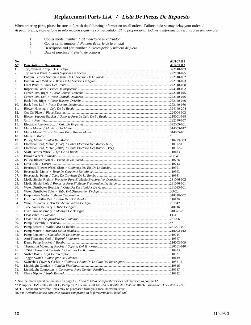
No. AU1C7112N° Description / Descripción AU2C71121. Top, Cabinet / Tapa De La Caja ...........................................................................................................................322140-0532. Top Access Panel / Panel Superior De Acceso ......................................................................................................222130-0753. Bottom, Blower Section / Base De La Sección De La Rueda ...............................................................................222140-0524. Bottom, Wet Module / Base De La Sección De Agua ...........................................................................................222130-0735. Front Panel / Panel Del Frente ..............................................................................................................................222140-0586. Inspection Panel / Panel De Inspección ................................................................................................................224140-0027. Center Post, Right / Poste Central, Derecho .........................................................................................................222140-0458. Center Post, Left / Poste Central, Izquierdo ..........................................................................................................222140-0469. Back Post, Right / Poste Trasero, Derecho ...........................................................................................................222140-04910. Back Post, Left / Poste Trasero, Izquierdo ............................................................................................................222140-05011. Blower Housing / Caja De La Rueda ....................................................................................................................324140-20412. Cut-Off Plate / Placa Externa ................................................................................................................................224004-00313. Blower Support Bracket / Soporte Para La Caja De La Rueda ............................................................................218001-03814. Grill / Parrilla ........................................................................................................................................................222140-05715. Electrical Junction Box / Caja De Empalme .........................................................................................................322009-00116. Motor Mount / Montura Del Motor .......................................................................................................................314003-01217. Motor Mount Clips / Seguros Para Montar Motor ...............................................................................................314005-00118. Motor / Motor ........................................................................................................................................................*19. Pulley, Motor / Polea Del Motor ...........................................................................................................................110279-00320. Electrical Cord, Motor (115V) / Cable Eléctrico Del Motor (115V) .....................................................................110372-120. Electrical Cord, Motor (230V) / Cable Eléctrico Del Motor (230V) ....................................................................110372-221. Shaft, Blower Wheel / Eje De La Rueda ...............................................................................................................11018322. Blower Wheel / Rueda ...........................................................................................................................................20BW23. Pulley, Blower Wheel / Polea De La Rueda ..........................................................................................................11027624. Drive Belt / Correa ................................................................................................................................................11021325. Bearings, Blower Wheel Shaft / Cojinetes Del Eje De La Rueda .........................................................................11035126. Receptacle, Motor / Toma De Corriente Del Motor ..............................................................................................11039327. Receptacle, Pump / Toma De Corriente De La Bomba .........................................................................................11036128. Media Shield, Right / Protector Para El Medio Evaporativo, Derecho................................................................281046-00229. Media Shield, Left / Protector Para El Medio Evaporativo, Izquierdo ................................................................281046-00130. Water Distributor Housing / Caja Del Distribuidor De Agua ...............................................................................281033-00131. Water Distributor Tube / Tubo Del Distribuidor De Agua ....................................................................................3D-2332. Evaporative Media / Medio Evaporativo ...............................................................................................................310118-00233. Distributor Filter Pad / Filtro Del Distribuidor .....................................................................................................11012034. Water Reservoir / Bandeja Acumuladora De Agua ...............................................................................................28104235. Tube, Water Delivery / Tubo De Agua ...................................................................................................................31071636. Over Flow Assembly / Montaje De Desagüe ........................................................................................................310571-237. Float Valve / Flotador ............................................................................................................................................FL-C38. Float Shield / Salpicadero Del Flotador ................................................................................................................28100639. Pump Assembly / Bomba .......................................................................................................................................**40. Pump Screen / Malla Para La Bomba ...................................................................................................................281001-00141. Pump Mount / Montura De La Bomba ..................................................................................................................218002-01242. Pump Retainer / Sujetador De La Bomba..............................................................................................................11071443. Anti-Flattening Coil / Espiral Protectora ..............................................................................................................11084744. Dump Pump Bracket / Bomba ...............................................................................................................................216003-00945. Thermostat Mounting Bracket / Soporte Del Termostato ......................................................................................220101-01046. T’Stat Thermostat Controls / Controles De Termostato ........................................................................................11042347. Switch Box / Caja De Interuptor...........................................................................................................................11082148. Toggle Switch / Interuptor De Palanca .................................................................................................................11041949. Switchbox Cover & Gasket / Cubierta y Junta De La Caja Del Interruptor ........................................................110821-150. Liquidtight Conduit / Conduit Flexible .................................................................................................................11081651. Liquidtight Connectors / Conectores Para Conduit Flexible ................................................................................11081752. Chase Nipple / Niple Roscado ...............................................................................................................................110812
* See the motor specifi cation table on page 12. / Vea la tabla de especifi caciones del motor en la página 12.** Pump for 115V units - #110436, Pump for 230V units - #C60P-240 / Bomba de 115V - #110436, Bomba de 230V - #C60P-240NOTE: Standard hardware items may be purchased from your local hardware store.NOTA: Artículos de uso corriente pueden comprarse en la ferretería de su localidad.
Replacement Parts List / Lista De Piezas De RepuestoWhen ordering parts, please be sure to furnish the following information on all orders. Failure to do so may delay your order. /Al pedir piezas, incluya toda la información siquiente con su pedido. El no proporcionar toda esta información resultará en una demora.
1. Cooler model number / El modelo de su enfriador 2. Cooler serial number / Número de serie de la unidad 3. Description and part number / Descripción y número de pieza 4. Date of purchase / Fecha de compra

11110498-3
Replacement Parts / Piezas De Repuesto
AU1C7112, AU2C7112

12 110498-3
Lea Y Conserve Estas Instrucciones
Reglas De Seguridad1. Lea las instrucciones con cuidado.
2. Las conexiones eléctricas deben ser hechas por un electricista com-petente, para que todo el cableado eléctrico cumpla con los requisitos establecidos en su localidad.
3. Siempre CORTE LA CORRIENTE y DESCONECTE el motor y la bomba en el interior del aparato antes de instalar o realizar cualquier labor de mantenimiento.
4. El motor y la bomba están provistos de clavijas moldeadas, con toma de tierra, y se apagarán automáticamente en caso de sobrecalentamiento. Los motores volverán a funcionar cuando se enfrían.ADVERTENCIA: Para reducir el riesgo de incendio o toques
eléctricos, no use este ventilador con ningún “dispositivo de estado sólido para controlar la velocidad del ventilador.”
Enfriamiento Por EvaporaciónEl enfriamiento por medio de evaporación es la manera de la naturaleza de refrescarse. Cuando el aire se mueve sobre una superfi cie mojada, se evapora el agua y se absorbe el calor. Al salir de una piscina con el viento que sopla usted se siente fresco, aunque el aire puede ser caliente. El cuerpo humano sí mismo es refrescado principalmente por la evapo-ración del sudor.
Este enfriador funciona usando el mismo principio. El aire se traza a través de los fi ltros mojados donde el aire se enfría por medio de evapo-ración y después circula a través del edifi cio. Se hace frío de la sensación cuando tiene esta combinación del aire enfriado y del movimiento del aire sobre la piel.
A diferencia de los acondicionadores de aire que recirculan el aire, un enfriador evaporativo trae continuamente por dentro el aire fresco mientras agota el aire viejo. Se reemplaza completamente el aire cada 2 a 4 minutos, abriendo las ventanas o las puertas o una combinación de ambas. El aire es siempre fresco, no es viciado, cargado de humo y olores como ocurre con los sistemas de aire acondicionado a base de refrigeración.
Motor Specifi cations / Especifi caciones Del Motor
General Specifi cations / Especifi caciones Generales
ModelsModelos
Weight (lbs.)Peso (libras)
Cabinet Dimensions (in.)Dimensiones De La Caja (pulgadas)
Duct Opening (in.)Abertura De Ducto (pulgadas)
DrySeco
OperatingLleno
HeightAltura
WidthAnchura
DepthProfundidad
WidthAnchura
HeightAltura
AD1C51, AD2C51, AS1C51,AS2C51
183 233 28 42 45 17 3/4 17 3/4
AD1C5112, AD2C5112,AS1C5112, AS2C5112
196 263 28 42 49 17 3/4 17 3/4
AD1C71, AD2C71,AS1C71, AS2C71
219 269 34 5/8 42 48 19 3/4 19 3/4
AD1C7112, AD2C7112,AS1C7112, AS2C7112,AU1C7112, AU2C712
239 306 34 5/8 42 52 19 3/4 19 3/4
ModelsModelos
HPC.V.
Motor #Motor-N°
SpeedVelocidad
VoltsVoltios
*AmpsAmperaje
Motor Pulley #Polea Del Motor-N°
ModelModelo
Drive Belt Part #Correa - N°
AD1C51,AD1C5112,
AS1C51,AS1C5112
3/4 110449 2 115 10.5 110279-004
AD1C51,AD1C5112
110229 (4L-530)
AS1C51,AS1C5112
110212 (4L-570)
AD2C51,AD2C5112,
AS2C51,AS2C5112
3/4 110480 2 230 5.1 110279-004
AD2C51,AD2C5112
110229 (4L-530)
AS2C51,AS2C5112
110212 (4L-570)
AD1C71,AD1C7112,
AS1C71,AS1C7112,AU1C7112
1 110471 2 115 12.3 110279-003
AD1C71,AD1C7112
110230 (4L-640)
AS1C71,AS1C7112
110213 (4L-670)
AU1C7112 110213 (4L-670)
AD2C71,AD2C7112,
AS2C71,AS2C7112,AU2C7112
1 110458 2 230 6.2 110279-003
AD2C71,AD2C7112
110230 (4L-640)
AS2C71,AS2C7112
110213 (4L-670)
AU2C7112 110213 (4L-670)
* Motor amperage shown is for high speed. / El amperaje listado es para la velocidad alta.

13110498-3
Conectar El Agua• Instale el montaje de desagüe. Quite la
tuerca y pase la boquilla por el agujero de la bandeja, colocando la arandela de goma entre la bandeja y la cabeza de la boquilla (véase fi g. 2). Coloque la tuerca en la boquilla y atorníllela hasta que quede apretada contra la parte inferior de la bandeja. Inserte el tubo de desagüe en la boquilla para retener el agua. El tubo de desagüe viene de la fábrica conectado a la manguera de la bomba de desagüe. El tubo de desagüe se puede quitar para desaguar el agua de la bandeja cuando sea necesario. Se puede conectar una mangue-ra de jardín a la boquilla para desaguar el agua hacia otra parte.
• Conecte el tubo de abastecimiento de agua. Instale la llave de paso y la válvula de agua en el grifo según indica la fi gura 3. Coloque la tuerca y la férula en el tubo y apriete bien la tuerca para impedir que gotee el agua. NOTA: No conecte el abas-tecimiento de agua con ninguna aplicación de agua blanda.
• Instale la válvula del fl otador y llene la bandeja con agua. Véase la fi gura 4. Remueve los partes 1, 2, 3 y 4. Inserte el cuerpo del fl otador (5) por el agujero en el poste trasero segun lo indicado. Instale la arandela (1) y la tuerca (2). Apriete la tuerca para que el fl otador no de vuelta. Ponga la tuerca (4) y la férula (3) en la línea de abastecimiento de agua. Conecte la línea al fl otador y apriete la tuerca hasta que no salga agua. Doble la varilla (6) para ajustar el fl otador hasta que el nivel del agua esté a una altura de 1 pulgada por debajo de la tapa del tubo de des-agüe. Ponga el salpicadero del fl otador (7) sobre el cuerpo del fl otador hasta que se agarre.
Instalación Del EnfriadorPRECAUCIÓN: La superfi cie en que ha de colocarse el en-
friador deberá aguantar el peso completo de la unidad cuando ésta está en funcionamiento. (Para saber este peso, vea la tabla de especifi caciones.)
PRECAUCIÓN: No conecte el enfriador hasta que la instala-ción esté completa y se haya comprobado la estabilidad del mismo.
PRECAUCIÓN: No atornille ni taladre a 5 pulgadas del fondo de la sección de agua. Usted podría pinchar la bandeja acumuladora de agua.
NOTA: Para una instalación más fácil, puede separar la sección de agua de la sección de la rueda quitando los cuatro pestillos del lado de la sección de agua (fi g. 1). Desenchufe las dos bombas antes de separar las secciones.
alimentación eléctrica se debe proteger adecuadamente contra sobrecargas y circuitos cortos. Recomendamos el uso de un cortacircuito de 20 amperios para la alimentación de 120V o un cortacircuito de 15 amperios para la ali-mentación de 230V. Nota: La instalación eléctrica se debe realizar por un electricista cualifi cado. Siga todos los códigos eléctricos nacionales y locales al instalar este enfriador.
• Instale la caja de interruptor. Dentro de la unidad está un bolso plástico que contiene la caja y cubierta del interruptor, una niple roscada, un anillo de estanquidad y un interruptor de palanca. Quite la caja de empalme eléctrica que se encuentra en el interior del panel central (véase Fig 5). Por dentro de la unidad, inserte la niple roscada a través del agujero de acceso eléctrico. Resbale el anillo de estanquidad sobre la niple roscada. Instale la caja del interruptor al exterior de la unidad atornillando la niple roscada en la caja del interruptor. Inserte los tres conductores del interruptor a tra-vés de la niple roscada y en la caja del interruptor y reinstale la caja de empalme. Conecte el conductor a tierra verde al tornillo de puesta a tierra en la caja del interruptor.
• Suministre electricidad a la unidad. Tienda cables de alimentación hasta la caja del interruptor externo y conéctelos con los dos polos del interruptor de palanca. Conecte los conductores gris y blanco de la caja eléctrica de enfriador con los dos polos del interruptor de palanca. Refi era al diagrama eléctrico apropiado para terminar la instalación eléctrica de su enfriador. Coloque el interruptor en la caja del interruptor e instale la junta y la cubierta de la caja de interruptor.
PRECAUCIÓN: Todas las aberturas de la caja externa de interruptor se deben sellar para evitar la entrada del agua.
PRECAUCIÓN: Los enchufes de la bomba están para las bombas puestas a tierra del enfriador evaporativo solamente. No enchufe cualquier otra cosa en los enchufes.
ADVERTENCIA: Compruebe que la caja del enfriador tenga la debida conexión a tierra para proveer máxima seguridad.
Instalación Del Termostato1) Localice una localización apropiada para el termostato de pared (lejos de
fuentes del calor, de la luz del sol, o de la ventilación, y entre 4 y 6 pies del piso). El termostato se puede montar a una caja eléctrica estándar.
2) Tienda un cable aislado de termostato con cuatro conductores (o similar) desde la caja de control dentro del enfriador hasta la caja eléctrica del termostato. Este cable no está provisto. ADVERTENCIA: El cable de termostato no debe ser encaminado al lado de o entrar el enfriador a través de la misma entrada del cable de alimentación.
3) Conecte los conductores del cable de termostato a los terminales por detrás del control de pared y a los terminales localizados en el lado izquierdo de la caja de control dentro de la unidad. Siga el código de color encontrado al lado de cada terminal.
Instalación EléctricaADVERTENCIA: Desconecte todos los servicios eléctricos que
serán usados en esta unidad antes de instalar el enfriador y queda desconectada hasta que la instalación es completa.
La caja de control es instalado y atado con alambre en la fábrica para el alimentación de 120V o de 230V, dependiendo del modelo comprado. La
Amperio Y Tensión De La CorreaEsta unidad viene equipada de una polea ajustable que permite ajustar la velocidad del ventilador según la capacidad del motor en sistemas diferentes de conductos. Es importante que la polea del motor sea ajustada al tamaño correcto, para asegurar el máximo rendimiento sin dañar el motor. Siga cuidadosamente estas instrucciones.
• Ajuste la polea del motor. Después de instalar el enfriador completo, ajuste la polea al diámetro mínimo y ajuste la tensión de la correa. Vea la sección de mantenimiento para ajustar la correa.
Sección De Agua
Fig. 1
Pestillos
Grifo
Valv
ula
De A
gua
Llave De Paso
Feru
laTu
erca
Fig. 3
12
34
5
6
7
Fig. 4
Arandela De Goma
Tubo De Desagüe
Boquilla Roscada
BandejaTuerca
Fig. 2
Manguera De La Bomba de Desagüe
Fig. 5
Caja Eléctrica
Anillo De Estanquidad
Caja De Empalme
Niple Roscada

14 110498-3
• Poner en marcha la unidad. Instale los paneles de inspección, prenda la bomba y permita que siga funcionando hasta que todos los fi ltros estén mojados.
• Revise el amperio. Con los fi ltros mojados y la unidad en funciona-miento, revise el amperio del motor con un medidor de amperio.
• Ajuste la polea si es necessario. Si la lectura de amperio es menos del valor especifi cado del motor, apague la unidad y quite el panel de inspección (la tapa para modelos ADA35 y ASA35). Desconecte el motor dentro de la caja para protegerse en caso de que alguien intente poner en marcha el aparato mientras usted está trabajando. Esto hay que hacerlo por su pro-pia seguridad. Ajuste la polea a un diámetro mas grande y vuelva a ajustar la tensión de la correa. Conecte el motor, coloque el panel y compruebe de nuevo el amperio. Repita estos pasos hasta obtener la lectura de amperio co-rrecta. El incrementar el diámetro de la polea, incrementa también el amperio; el disminuir el diámetro de la polea, disminuye también el amperio (véase fi g. 6).PRECAUCIÓN: No permita que funcione esta unidad si toma
mas amperio del que se indica la placa del motor.
NOTA: No se debe intentar la instalación completa de esta unidad sin la ayuda de un electricista o alguien que sepa medir el amperio. Si usted no sigue esta instrucción, podrá ser anulada su garantía.
Wet’ y comenzará el ventilador y la bomba inmediatamente. (Si se requiere refrescarse).
Durante el funcionamiento automático, el control realiza un ciclo de la descarga de agua que dura 90 segundos cada 8 o 12 horas del funcionamiento de la bomba. Este intervalo se puede cambiar entre 8 o 12 horas simultáneamente sosteniendo los botones ‘Fan’ y ‘Cool’ por 5 segundos. El intervalo seleccio-nado se indica por un tiempo corto. Esta acción también comienza un ciclo manual de la descarga de agua.
Funcionamiento Del Ventilador (Modo de Ventilador)La velocidad del ventilador es determinado por el usuario, la bomba de agua está apagada.
Este modo es activado presionando el botón ‘Fan’. Un diodo LED verde está iluminado y el LCD indica la velocidad del ventilador. Al presionar el botón ‘Fan’ otra vez desactiva este modo.
Al presionar el botón ‘Arriba’ selecciona la velocidad máxima del ventilador y el LCD indica ‘Hi’. Al presionar el botón ‘Abajo’ selecciona la velocidad mínima del ventilador y el LCD indica ‘Lo’.
Funcionamiento Retardado (Modo de Temporizador)Retardo del empieza o fi n en el modo ‘Cool’ o ‘Fan’
El botón ‘Timer’ (temporizador) está utilizado para determinar un retardo de 2, 4 o 8 horas, dependiendo en las veces que presione el botón.
Si el enfriador está funcionando en el modo ‘Cool’ o ‘Fan’ cuando presiona el botón ‘Timer’, el periodo de retraso se determina cuando el enfriador apagará. Si el enfriador está apagada cuando presiona el botón ‘Timer’, el período de retraso se determina cuando arranque el enfriador.
El modo de empezar se indica por un diodo LED que destella. Se puede cambiar este modo presionando el botón apropiado (‘Cool’ o ‘Fan’).
Se puede cancelar la función del temporizador en cualquier momento pre-sionando el botón ‘Timer’ hasta no ilumina ninguno de los diodos LED de temporizador.
En Caso de una Interrupción de la EnergíaSi el enfriador está funcionando en el modo ‘Cool’ o ‘Fan’ cuando se inte-rrumpe la energía, el enfriador reasumirá en el mismo modo cuando restaura la energía.
Si el enfriador estaba en cualquier modo del temporizador cuando interrumpe la energía, el enfriador será apagada cuando restaura la energía.
Esquemas Del Cableado120 Voltios 240 Voltios
Funcionamiento Del Termostato
Funcionamiento Automático (Modo de Enfriador)El ventilador y la bomba de agua se controlan automáticamente para alcanzar el nivel deseado de la comodidad.
Este modo es activado presionando el botón ‘Cool’. Un diodo LED de azul está iluminado, y por algunos segundos el LCD exhibirá la temperatura ‘Objetiva’. Presionar el botón “Cool” otra vez desactiva este modo.
La temperatura ‘Objetiva’ (la temperatura objetiva para el control) se puede cambiar presionando o sosteniendo el botón ‘Arriba’ o ‘Abajo’. El LCD indicará la temperatura ‘Objeto’ en vez de la temperatura del ‘Cuarto’ por un tiempo corto después de presionar el botón ‘Arriba’ o ‘Abajo’.
Al funcionar, si los fi ltros en el enfriador son demasiado secos, el ventilador se puede retrasar de comenzar hasta que los fi ltros han absorbido un poco de agua. Esto se llama ‘Pre-Wet’ y dura por 2 minutos, indicado por un LED azul que destella. Seleccionar ‘Fan’ y después ‘Cool’ evitará el ciclo ‘Pre-
Disminuir Amperio
Fig. 6
VIOLETAAZUL
AMARILLO
GRISNEGROROJO
VERDEBLANCO
GRIS
TIERRA
INTERRUPTOR DE PALANCA
(11)
FLoFH
iFC
om
LINK L1 N
NLink
PP
PC
om DP
DC
om
DUMPPUMPFAN PWR. SUPPLY
ENCHUFE DEL
TERMOSTATO
MOTOR
DE AGUAENCHUFE DE BOMBA
BOMBA DE DESAGÜEENCHUFE DE
120 VAC
BLANCO
NARANJA
NARANJAMARRÓN
MARRÓNNARANJA
AZULBLANCOVERDE
CONDUCTORESDEL INTERRUPTOR
ROJO
CAJA DE EMPALME DEL ENFRIADOR
BLANCOVERDE
NEGRO
VERDEBLANCO
AZUL
=EMPALME PLÁSTICO
VERDEBLANCO
AZULNARANJAMARRÓN
MARRÓNNARANJA
NARANJA
BLANCO
240 VAC
ENCHUFE DE LABOMBA DE DESAGÜE
ENCHUFE DE LABOMBA DE AGUA
MOTOR
THERMOSTATO
ENCHUFE DEL
PWR. SUPPLYFAN PUMP DUMP
DC
omDP
PC
omPP
NLinkNL1
LINK
FComFH
iFLo
(11)
INTERRUPTOR DE PALANCA
TIERRA
GRISBLANCOVERDE
ROJONEGRO
GRIS
AMARILLOAZUL
VIOLETA
=EMPALME PLÁSTICO
BLANCOVERDE
NEGRO
VERDEBLANCO
CAJA DE EMPALME DEL ENFRIADOR
ROJO
AZUL
CONDUCTORESDEL INTERRUPTOR

15110498-3
IMPORTANTE: Para que el enfriador funcione lo mejor, debe instalar el medio evaporativo correctamente. Si usted ha comprado fi ltros con dos ángulos iguales, las instrucciones siguientes no serán provechosas para usted. Los fi ltros deben ser instalados con el ángulo más escar-pado inclinándose por la entrada del aire (véase fi g. 7). La razón es que el ángulo más escarpado le ayuda a poner más agua en el lado seco y caliente donde lo necesita más. También le ayuda a contrarrestar la tendencia del aire a empujar el agua hasta atrás de los fi ltros.
• Limpie la bomba. Es necesario limpiar la bomba una vez al principio de cada año. Por su propia seguridad, apague la unidad y desconecte el motor y la bomba. Quite el sujetador de plástico de la montura y quite la bomba, deslizándola hacia usted. Quite la base de la bomba según se muestra en la fi gura 8. Limpie la bomba. Dé le vuelta a la hélice para verifi car que se mueve libremente. Quite el pico de la bomba y vea si está obstruido. Después de limpiar, reinstale la base en la bomba. Presione fi rmemente para asegurarse de que es segura. Vuelva a colocar la bomba en la unidad y fíjela en la montura con el sujetador de plástico. Esto impedirá que se caiga la bomba al agua, lo que dañaría el motor. No se olvide de volver a conectar el tubo de agua a la bomba.
• Compruebe la tensión de la correa. Una fuerza de 3 libras debe desviar la correa 3/4 pulgadas (véase fi g. 9). Ajuste la correa si es necesario.
• Lubrique los cojinetes. Los cojinetes de la rueda y el motor del ventilador deben ser lubricados usando unas gotas de un aceite no detergente de densidad 20/30 una vez al año. No obstante, los motores sin tuberías para aceite no necesitan ser lubricados. Estos motores son lubricados en la fábrica de por vida y no requieren nunca ninguna lubricación. PRECAUCIÓN: No lubrique demás. El agregar demasiado aceite
puede ocasionar que se queme el motor, a causa del aceite entrando al interior del motor.
• Compruebe la válvula de desahogo para verifi car que no esté obs-truida.
Preparar La Unidad Para El Invierno• Drene el agua. Drene siempre toda el agua de la unidad y del tubo de
abastecimiento de agua cuando no use el enfriador durante períodos pro-longados, especialmente al fi n de la temporada. El tubo debe quedarse desconectado del enfriador y del abastecimiento de agua para que no lo congele.
• Desconecte el motor y la bomba dentro del enfriador cuando no se utiliza el enfriador por períodos extendidos.
• Cubra la unidad. Para proteger y alargar la vida útil del acabado, se sugiere cubrir el enfriador durante períodos largos cuando no sea utili-zado.
Si usted sigue estas sugerencias en cuanto a instalación, operación y mante-nimiento, podrá disfrutar de muchos años de servicio efi ciente y satisfactorio de este enfriador. Si desea más información, su concesionario tendrá mucho gusto en ayudarle con respecto a cualquier duda o pregunta.
¿Cuanto Debe Abrir Las Ventanas?Un concepto a menudo entendido mal de enfriamiento por evaporación es la cantidad de aire que debe ser agotada. Cuánto debe usted abrir sus ventanas? El hecho es que la mayoría de la gente no abre sus ventanas bastante. Los dos métodos siguientes le ayudarán.
El Método PrimeroUsted debe dejar una abertura de dos pies cuadrados por cada 1000 P.C.M. (pies cúbicos por minuto), según la capacidad de su modelo. Ejemplo: Un Modelo AD1C51 (3/4 c.v.) de 3790 P.C.M. requiere 7,6 pies cuadrados (1094 pulgadas cuadradas) de abertura (3790/1000 * 2 = 7,6). Ahora, multiplique el número de las ventanas por el ancho de las mismas; luego divida esta can-tidad entre el número de pulgadas cuadradas requeridas para su unidad. El resultado le dice hasta qué altura hay que abrir las ventanas. En este ejemplo, cuatro ventanas que miden 36 pulgadas (0,9 m) de ancha se deben abrir 7,6 pulgadas por cada una.
El Método De Equilibrar El Aire1. Tome un pedazo de papel de seda y córtelo a lo largo en 3 tiras igua-
les. 2. Ponga en marcha a su enfriador a “High-Cool”. 3. Abra una ventana por lo menos seis pulgadas de ancho en cada sitio
que usted desee refrescar. 4. Tome un pedazo de papel de seda y póngalo contra la pantalla de la
ventana abierta más lejos de la apertura del enfriador. Suéltalo al papel de seda. Hará una de tres cosas:
SI: Se caiga.ENTONCES: CIERRE todas las ventanas una pulgada e intente el
paso 4 otra vez.
SI: Se queda contra la pantalla con fuerza.ENTONCES: ABRA todas las ventanas una pulgada e intente el paso
4 otra vez.
SI: Se queda ligeramente contra la pantalla.ENTONCES: PERFECTO. Se ha acabado. Goce del aire refrescan-
te.Notas: • Al poner el enfriador a “low-cool”, usted debe reequilibrar el aire de
su hogar. Repita el paso 4. • Al equilibrar el aire de su hogar usted puede refrescar algunas áreas
más que otras abriendo esas ventanas más y cerrando las otras por la misma cantidad. Repita el paso 4. Asegurarse de que el aire de su hogar sea equilibrado.
MantenimientoADVERTENCIA: Antes de hacer cualquier mantenimiento,
compruebe que la corriente esté apagada. Al quitar un panel de inspección, desconecte el motor y la bomba dentro de la caja. Esto es por su seguridad.
Puesta En Marcha En La Primavera• Limpie el medio evaporativo. Un fi ltro limpio es más absorbente
y efi ciente y producirá un mayor volumen de aire frío. Cada año o cuando sea necesario, limpie con una manguera de jardín las aberturas. Luego limpie el lado de adentro de cualquier escama u otra obstrucción a las aberturas. Si requiere, raspe ligeramente para remover escama endurecida.
• Cambie el medio evaporativo después de 5 años o cuando sea ne-cessario. El cambiar el medio evaporativo, remueva el panel superior de acceso, remueva la parrilla y desconecte el tubo del distribuidor de agua. Quite la caja del distribuidor de agua y saque el medio evapora-tivo. Reemplace con los fi ltros de mismo tipo lo que puede encontrar de su comerciante.
45°
15°
Entrada Del Aire
Salida Del Aire
Fig. 7
Fig. 9
3 Libras3/4 Pulgadas
hélice
QuiteLa Base
Fig. 8
16 110498-3
1. No llega corriente • Fusible fundido • Cortacircuito desactiva-
do2. Motor recalentado • Correa muy apretada
• Cojinetes de la rueda están secos
• Diámetro de la polea del motor demasiado grande
3. Motor parado4. Fusible fundido en la caja
de control5. Cableado incorrecto entre
el termostato de pared y el enfriador
6. Conexiones malas a las terminales del motor
7. Tarjeta controladora de la unidad o termostato de pared defectuoso
1. Agua estancado en la unidad
1. Revise la corriente • Cambie el fusible • Restablecer el cortacircui-
to2. Determine la causa • Ajuste la tensión de la
correa • Lubrique los cojinetes
• Ajústela al diámetro correcto
3. Cambie el motor4. Cambie el fusible
5. Revise que el cableado es correcto y seguro
6. Revise las conexiones
7. Revise el voltaje DC al termostato de pared
• Si el voltaje entre los terminales negro y rojo está cerca de 3.5VDC y el LCD está en blanco - el termostato de pared es defectuoso
• Si el voltaje es mucho menos de 3.5VDC, quite el conductor rojo del terminal. Si el voltaje incrementa hasta 3.5VDC - el termostato de pared es defectuoso. Si el voltaje sigue siendo bajo - la tarjeta controladora es defectuosa
1. Desagüe y limpie el medio evaporativo
1. Abra ventanas o puertas para aumentar fl ujo de aire
2. Ajuste la tensión o cam-bie la correa
3. Limpie los fi ltros4. Ajuste la polea
1. Lubrique los cojinetes2. Inspeccione y alinee
(Desconecte la unidad)3. Apriételas
1. Compruebe el voltaje2. Ajuste la tensión de la
correa3. Lubrique o cambie los
cojinetes (Desconecte la unidad)
4. Lubrique los cojinetes5. Ajústela para no exceder
el grado a carga plena del amperio del motor
1. Abra más las ventanas o puertas
2. Revise la distribución de agua
• Limpie los fi ltros • Límpielos
• Cámbiela o límpiela (Desconecte la unidad)
1. Abra puertas o ventanas
1. Insufi ciente abertura para que salga el aire
2. Poca tensión en la correa
3. Filtros obstruidos4. Motor no se carga
1. Cojinetes secos2. Rueda roza contra caja de
la rueda3. Partes sueltas
1. Voltaje defi ciente2. Demasiada tensión en la
correa3. Eje del ventilador atorado
4. Cojinetes secos5. Diámetro demasiado
grande de la polea del motor dando por resulta-do sobrecarga del motor
1. Insufi ciente abertura para que salga aire
2. El medio evaporativo no está mojado
• Filtros obstruidos • Agujeros del tubo obs-
truidos • Bomba no funciona
1. Insufi ciente salida de aire
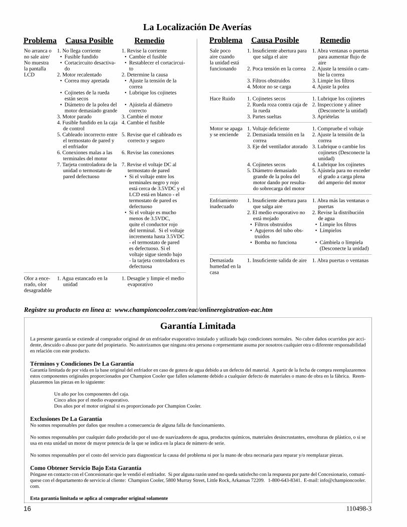
Problema Causa Posible Remedio Problema Causa Posible RemedioLa Localización De Averías
No arranca o no sale aire/ No muestra la pantalla LCD
Olor a ence-rrado, olor desagradable
Sale poco aire cuando la unidad está funcionando
Hace Ruido
Motor se apaga y se enciende
Enfriamiento inadecuado
Demasiada humedad en la casa
Garantía LimitadaLa presente garantía se extiende al comprador original de un enfriador evaporativo instalado y utilizado bajo condiciones normales. No cubre daños ocurridos por acci-dente, descuido o abuso por parte del propietario. No autorizamos que ninguna otra persona o representante asuma por nosotros cualquier otra o diferente responsabilidad en relación con este producto.
Términos y Condiciones De La GarantíaGarantía limitada de por vida en la base original del enfriador en caso de gotera de agua debido a un defecto del material. A partir de la fecha de compra reemplazaremos estos componentes originales proporcionados por Champion Cooler que fallen solamente debido a cualquier defecto de materiales o mano de obra en la fábrica. Reem-plazaremos las piezas en lo siguiente:
Un año por los componentes del caja. Cinco años por el medio evaporativo. Dos años por el motor original si es proporcionado por Champion Cooler.
Exclusiones De La GarantíaNo somos responsables por daños que resulten a consecuencia de alguna falla de funcionamiento.
No somos responsables por cualquier daño producido por el uso de suavizadores de agua, productos químicos, materiales desincrustantes, envolturas de plástico, o si se usa en esta unidad un motor de mayor potencia de la que se indica en la placa de número de serie.
No somos responsables por el costo del servicio para diagnosticar la causa del problema ni por la mano de obra necesaria para reparar y/o reemplazar piezas.
Como Obtener Servicio Bajo Esta GarantíaPóngase en contacto con el Concesionario que le vendió el enfriador. Si por alguna razón usted no queda satisfecho con la respuesta por parte del Concesionario, comuní-quese con el departamento de servicio al cliente: Champion Cooler, 5800 Murray Street, Little Rock, Arkansas 72209. 1-800-643-8341. E-mail: [email protected].
Esta garantía limitada se aplica al comprador original solamente
Registre su producto en línea a: www.championcooler.com/eac/onlineregistration-eac.htm
Recommended