NIST GCR 12-917-18
Comparison of U.S. and Chilean Building Code
Requirements and Seismic Design Practice
1985–2010
NEHRP Consultants Joint Venture A partnership of the Applied Technology Council and the
Consortium of Universities for Research in Earthquake Engineering
Disclaimers
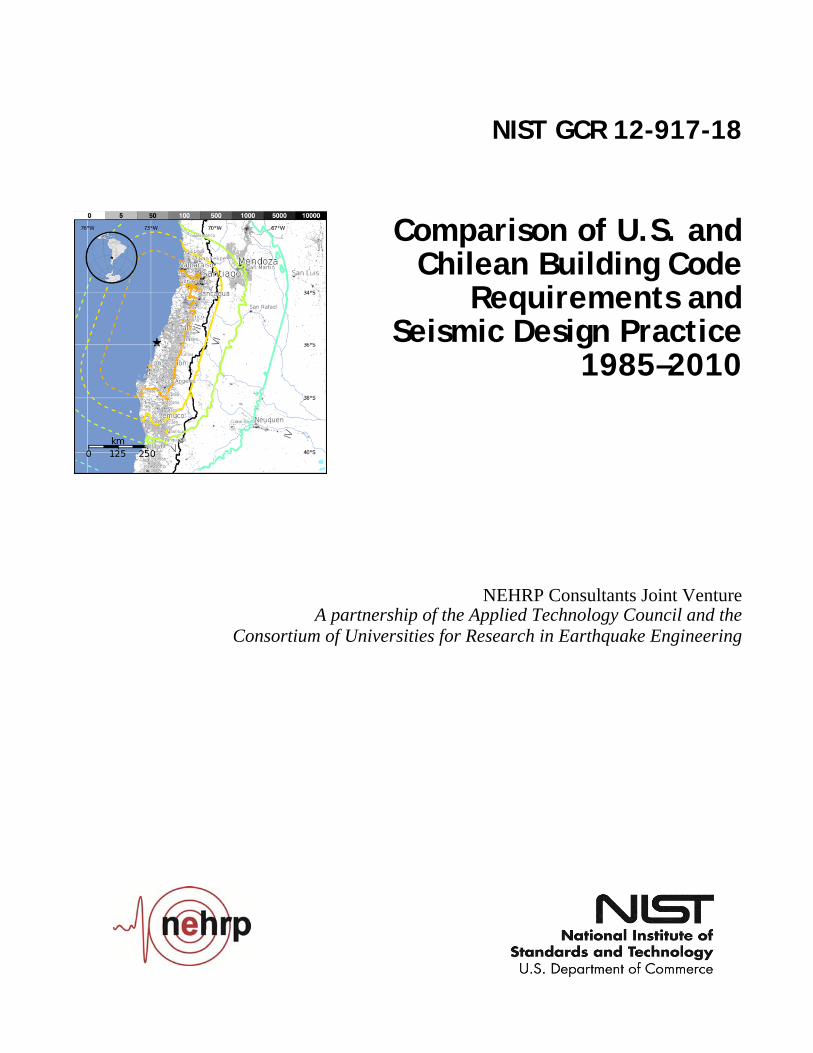
This report was prepared for the Engineering Laboratory of the National Institute of Standards and Technology (NIST) under the National Earthquake Hazards Reduction Program (NEHRP) Earthquake Structural and Engineering Research Contract SB134107CQ0019, Task Order 10279. The contents of this publication do not necessarily reflect the views and policies of NIST or the U.S. Government. This report was produced by the NEHRP Consultants Joint Venture, a joint venture of the Applied Technology Council (ATC) and the Consortium of Universities for Research in Earthquake Engineering (CUREE). While endeavoring to provide practical and accurate information, the NEHRP Consultants Joint Venture, the authors, and the reviewers assume no liability for, nor express or imply any warranty with regard to, the information contained herein. Users of information contained in this report assume all liability arising from such use. Unless otherwise noted, photos, figures, and data presented in this report have been developed or provided by NEHRP Consultants Joint Venture staff or consultants engaged under contract to provide information as works for hire. Any similarity with other published information is coincidental. Photos and figures cited from outside sources have been reproduced in this report with permission. Any other use requires additional permission from the copyright holders. Certain commercial software, equipment, instruments, or materials may have been used in the preparation of information contributing to this report. Identification in this report is not intended to imply recommendation or endorsement by NIST, nor is it intended to imply that such software, equipment, instruments, or materials are necessarily the best available for the purpose. NIST policy is to use the International System of Units (metric units) in all its publications. In this report, however, information is presented in U.S. Customary Units (inch-pound), as this is the preferred system of units in the U.S. earthquake engineering industry. Cover photo – Isoseismal Map, February 27, 2010, Maule earthquake (United States Geological Survey, 2011)
NIST GCR 12-917-18
Comparison of U.S. and Chilean Building Code Requirements and
Seismic Design Practice 1985–2010
Prepared for U.S. Department of Commerce
National Institute of Standards and Technology Engineering Laboratory
Gaithersburg, MD 20899
By NEHRP Consultants Joint Venture
A partnership of the Applied Technology Council and the Consortium of Universities for Research in Earthquake Engineering
October 2012
U.S. Department of Commerce
Rebecca M. Blank, Acting Secretary
National Institute of Standards and Technology Patrick D. Gallagher, Under Secretary of Commerce
for Standards and Technology, and Director


Participants National Institute of Standards and Technology
John (Jack) R. Hayes, Jr., Director, National Earthquake Hazards Reduction Program Steven L. McCabe, Deputy Director, National Earthquake Hazards Reduction Program
NEHRP Consultants Joint Venture
Applied Technology Council 201 Redwood Shores Parkway, Suite 240 Redwood City, California 94065 www.ATCouncil.org
Consortium of Universities for Research in Earthquake Engineering 1301 S. 46th Street, Building 420 Richmond, California 94804 www.CUREE.org
Joint Venture Management Committee
James R. Harris Robert Reitherman Christopher Rojahn Andrew Whittaker
Joint Venture Program Committee
Jon A. Heintz (Program Manager) Michael Constantinou C.B. Crouse James R. Harris William T. Holmes Jack Moehle Andrew Whittaker
Project Technical Committee
Ronald O. Hamburger (Project Director) Patricio Bonelli Rene Lagos Loring A. Wyllie, Jr.
Working Group Members
Ady Aviram Jose A. Flores Ruiz
NIST GCR 12-917-18

GCR 12-917-18 Preface iii
Preface
The NEHRP Consultants Joint Venture is a partnership between the Applied
Technology Council (ATC) and the Consortium of Universities for Research in
Earthquake Engineering (CUREE). In 2007, the National Institute of Standards and
Technology (NIST) awarded a National Earthquake Hazards Reduction Program
(NEHRP) “Earthquake Structural and Engineering Research” contract (SB1341-07-
CQ-0019) to the NEHRP Consultants Joint Venture to conduct a variety of tasks,
including Task Order 10279 entitled “Comparison of Present Chilean and U.S. Model
Building Code Seismic Provisions and Seismic Design Practices.”
This work is part of a series of investigations into the performance of engineered
construction during the February 27, 2010, Maule earthquake in Chile. It is intended
to provide an understanding of the similarities and differences between U.S. and
Chilean seismic design codes and practices so that meaningful conclusions can be
drawn from the observed performance of buildings in Chile, and that seismic-
resistant construction can be improved in the United States.
The NEHRP Consultants Joint Venture is indebted to the leadership of Ron
Hamburger, Project Director, and to the members of the Project Technical
Committee, consisting of Loring Wyllie, Patricio Bonelli, and Rene Lagos, who
identified and compared relevant code provisions and seismic design practices, and
developed the resulting observations and conclusions. Working groups, consisting of
Ady Aviram and Jose Flores Ruiz, provided translation services and performed
comparative design studies. A special debt of gratitude is owed to our Chilean
partners who collected and generously shared seismic design provisions, material
design standards, ground motions, comparative studies, and other information that
was instrumental in performing this work. The names and affiliations of all who
contributed to this report are provided in the list of Project Participants.
The NEHRP Consultants Joint Venture also gratefully acknowledges Jack Hayes
(NEHRP Director) and Steve McCabe (NEHRP Deputy Director) for their input and
guidance in the preparation of this report, and Peter N. Mork for ATC report
production services.
Jon A. Heintz
Program Manager

GCR 12-917-18 Table of Contents v
Table of Contents
Preface ................................................................................. iii
List of Figures ....................................................................... vii
List of Tables .......................................................................... xi
1. Introduction ................................................................ 1-1 1.1 Objectives and Scope ...................................................................... 1-1 1.2 Background Information ................................................................. 1-3
1.2.1 Geography, Population, and Industry ................................ 1-3 1.2.2 Regional Seismicity ........................................................... 1-4 1.2.3 Construction Practice ......................................................... 1-4
1.3 The Maule Earthquake of February 27, 2010 ................................. 1-5 1.4 Report Organization and Content ................................................. 1-10
2. Chilean Practice ........................................................... 2-1 2.1 Operative Codes .............................................................................. 2-1
2.1.1 NCh433 Loading Standard ................................................ 2-1 2.1.2 NCh430 Concrete Design Standard ................................... 2-3
2.2 Typical Chilean Design Practice ..................................................... 2-4 2.2.1 Seismic Design of Nonstructural Components ................ 2-10
2.3 Chilean Design Criteria ................................................................ 2-11 2.3.1 Seismic Zonation ............................................................. 2-11 2.3.2 Site Class ......................................................................... 2-12 2.3.3 Occupancy Categories ..................................................... 2-13 2.3.4 Load Combinations .......................................................... 2-13 2.3.5 Structural Systems ........................................................... 2-13 2.3.6 Analysis Procedures ......................................................... 2-14 2.3.7 Static Analysis ................................................................. 2-14 2.3.8 Modal Response Spectrum Analysis ............................... 2-17
3. U.S. Practice ............................................................... 3-1 3.1 Evolution of U.S. Seismic Design Codes ....................................... 3-1 3.2 Operative Codes .............................................................................. 3-3
3.2.1 ASCE 7 Loading Standard ................................................. 3-3 3.2.2 ACI 318 Concrete Design Standard ................................... 3-4
3.3 Typical U.S. Design Practice .......................................................... 3-4 3.4 U.S. Design Criteria ........................................................................ 3-8
3.4.1 Maximum Considered Earthquake Shaking ...................... 3-8 3.4.2 Site Class ......................................................................... 3-11 3.4.3 Design Earthquake Shaking ............................................. 3-12 3.4.4 Risk Category .................................................................. 3-13 3.4.5 Seismic Design Category ................................................. 3-13 3.4.6 Load Combinations .......................................................... 3-14 3.4.7 Structural Systems ........................................................... 3-16
vi Table of Contents GCR 12-917-18
3.4.8 Irregularities ..................................................................... 3-17 3.4.9 Analysis Procedures ......................................................... 3-18 3.4.10 Equivalent Lateral Force Procedure ................................. 3-19 3.4.11 Modal Response Spectrum Analysis ................................ 3-23
4. Comparison of U.S. and Chilean Seismic Design Requirements .............................................................. 4-1 4.1 Seismic Design Loading .................................................................. 4-1 4.2 Reinforced Concrete Seismic Design Provisions ............................ 4-2 4.3 Observations and Conclusions on U.S. and Chilean Seismic
Design Requirements ...................................................................... 4-3
5. Comparison of U.S. and Chilean Seismic Design Practice ......... 5-1 5.1 Building Description ....................................................................... 5-1 5.2 Observed Earthquake Damage ........................................................ 5-3 5.3 Analysis of Chilean Configuration .................................................. 5-6
5.3.1 Site Response Spectra ........................................................ 5-7 5.3.2 Drift Response .................................................................... 5-9 5.3.3 Design Forces ................................................................... 5-15
5.4 Design and Analysis of U.S. Configuration .................................. 5-19 5.4.1 Drift Response .................................................................. 5-21 5.4.2 Design Forces ................................................................... 5-23
5.5 Observations and Conclusions on U.S. and Chilean Seismic Design Practice .............................................................................. 5-25
References .......................................................................... A-1
Project Participants ................................................................ B-1
GCR 12-917-18 List of Figures vii
List of Figures
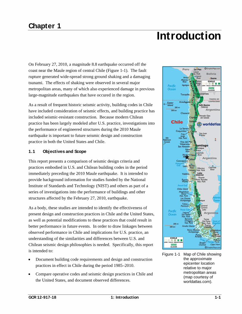
Figure 1-1 Map of Chile showing the approximate epicenter location relative to major metropolitan areas ................................................ 1-1
Figure 1-2 Partial collapse in the upper stories of the O’Higgins building in Concepción, Chile ....................................................................... 1-2
Figure 1-3 Collapse of the Alto Rio building in Concepción, Chile ................ 1-3
Figure 1-4 Isoseismal map of the 2010 Maule earthquake ............................... 1-6
Figure 1-5 Acceleration response spectra from all recording stations .............. 1-8
Figure 1-6 Acceleration response spectra from Santiago – Centro .................. 1-8
Figure 1-7 Acceleration response spectra from Viña del Mar – Centro ........... 1-9
Figure 1-8 Acceleration response spectra from Constitución ........................... 1-9
Figure 2-1 Typical mid-rise and high-rise buildings in Santiago ..................... 2-6
Figure 2-2 Typical mid-rise and high-rise buildings in Viña del Mar .............. 2-6
Figure 2-3 Typical floor plan of high-rise residential building in Chile .......... 2-7
Figure 2-4 Typical cross-section of mid-rise residential building in Chile ...... 2-7
Figure 2-5 Shallow lintel showing nominal reinforcement and lack of confinement in a residential building that was damaged in the 2010 Maule earthquake ................................................................... 2-8
Figure 2-6 Typical unconfined shear wall boundary zone detail permitted in NCh430 ....................................................................................... 2-9
Figure 2-7 Damage to typical unconfined shear wall boundary zone observed in the 2010 Maule earthquake ......................................... 2-9
Figure 2-8 Typical partially confined shear wall boundary zone details used by some Chilean engineers ............................................................. 2-9
Figure 2-9 Typical floor plan of high-rise office building in Chile ................ 2-10
Figure 2-10 Seismic zonation maps for northern, central, and southern Chile contained in NCh433 ........................................................... 2-11
Figure 2-11 Variation in seismic coefficient, C, as a function of period, T*, in Zone 3, assuming R=7 .............................................................. 2-16
Figure 2-12 Story force distribution as a fraction of base shear, for a hypothetical 10-story structure ..................................................... 2-17
viii List of Figures GCR 12-917-18
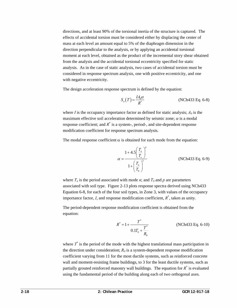
Figure 2-13 Acceleration response spectra in Zone 3, with R* and importance factor, I, taken as unity ............................................... 2-19
Figure 2-14 Variation in response modification coefficient, R*, as a function of site class and structural period, using NCh433 Equation 6-10, assuming R0 =11 ............................................................................ 2-19
Figure 2-15 Variation in response modification coefficient, R*, as a function of site class and number of stories, N, using NCh433 Equation 6-11, assuming R0 =11 ................................................................... 2-20
Figure 3-1 Typical floor plan of high-rise residential construction in the United States ................................................................................... 3-5
Figure 3-2 Alternative floor plan typically associated with mid-rise residential construction in the United States ................................... 3-5
Figure 3-3 Typical coupled shear wall elevation in the United States .............. 3-6
Figure 3-4 Ductile detailing for reinforcement of flexure-controlled coupling beams ................................................................................ 3-6
Figure 3-5 Ductile detailing for reinforcement of shear-controlled coupling beams ............................................................................................... 3-7
Figure 3-6 Alternative detailing for reinforcement of shear-controlled coupling beams permitted by ACI 318-11 ...................................... 3-7
Figure 3-7 Typical confined shear wall boundary zone .................................... 3-8
Figure 3-8 Risk-Adjusted Maximum Considered Earthquake (MCER) SS contour map for the Western United States ................................... 3-10
Figure 3-9 Risk-Adjusted Maximum Considered Earthquake (MCER) S1 contour map for the Western United States ................................... 3-11
Figure 3-10 Variation in base shear coefficient, CS, as a function of period, T, for Risk Category II, special reinforced concrete bearing wall structures located in regions of high seismicity ............................ 3-21
Figure 3-11 Story force distribution as a fraction of base shear, for a hypothetical 10-story structure with T=1 second .......................... 3-22
Figure 3-12 Generalized design response spectra for various site classes, with R and Ie taken as unity ........................................................... 3-24
Figure 5-1 Typical floor plan, Chilean case study building .............................. 5-2
Figure 5-2 Transverse wall elevations, Chilean case study building ................ 5-2
Figure 5-3 Transverse elevation of the case study building showing differential vertical displacements following the 2010 Maule earthquake ....................................................................................... 5-3
Figure 5-4 Overall damage sustained in the first-story transverse shear walls of the case study building ................................................................ 5-4
GCR 12-917-18 List of Figures ix
Figure 5-5 Cracking, spalling, crushing, and bar buckling in the transverse shear wall on Line 9 ........................................................................ 5-4
Figure 5-6 Cracking, spalling, crushing, and bar buckling in the transverse shear wall on Line 5 ........................................................................ 5-5
Figure 5-7 Crushing and bar buckling in the transverse shear wall on Line 1 resulting in significant differential vertical displacement ............... 5-5
Figure 5-8 Three-dimensional ETABS model of the Chilean configuration of the case study building ............................................................... 5-6
Figure 5-9 Comparison of design response spectra for Viña del Mar, per NCh433.Of96, and San Francisco, California, per ASCE/SEI 7-05 ............................................................................... 5-8
Figure 5-10 Variation in response modification coefficient, R*, as a function of period .......................................................................................... 5-9
Figure 5-11 Spectral acceleration ordinates for the Viña del Mar site divided by the value of R* at each period .................................................. 5-10
Figure 5-12 Maximum story drift ratios in the longitudinal direction at the center of mass, calculated per NCh433.Of96 ............................... 5-11
Figure 5-13 Maximum story drift ratios in the longitudinal direction at an extreme corner, calculated per NCh433.Of96 .............................. 5-11
Figure 5-14 Maximum story drift ratios in the transverse direction at the center of mass, calculated per NCh433.Of96 ............................... 5-12
Figure 5-15 Maximum story drift ratios in the transverse direction at an extreme corner, calculated per NCh433.Of96 .............................. 5-12
Figure 5-16 Maximum story drift ratios in the longitudinal direction at the center of mass, calculated per ASCE/SEI 7-05 ............................. 5-13
Figure 5-17 Maximum story drift ratios in the longitudinal direction at an extreme corner, calculated per ASCE/SEI 7-05 ............................ 5-13
Figure 5-18 Maximum story drift ratios in the transverse direction at the center of mass, calculated per ASCE/SEI 7-05 ............................. 5-14
Figure 5-19 Maximum story drift ratios in the transverse direction at an extreme corner, calculated per ASCE/SEI 7-05 ............................ 5-14
Figure 5-20 Design story shears in the transverse direction, per NCh433.Of96 (at strength level) and ASCE/SEI 7-05 (including redundancy factor) ............................................................................................ 5-17
Figure 5-21 Design overturning moments in the transverse direction, per NCh433.Of96 (at strength level) and ASCE/SEI 7-05 (including redundancy factor) ........................................................................ 5-17
x List of Figures GCR 12-917-18
Figure 5-22 Shear wall boundary element detailing for the case study building: (a) Chilean detailing; and (b) ACI 318 detailing for confinement ................................................................................... 5-18
Figure 5-23 Strain distribution and confined boundary element for “T-shaped” wall configurations, per ACI 318 .................................................. 5-18
Figure 5-24 Comparison of U.S. configuration with Chilean shear wall layout ............................................................................................. 5-19
Figure 5-25 Comparison of typical transverse wall elevations: (a) Chilean configuration; and (b) U.S. configuration ..................................... 5-20
Figure 5-26 Three-dimensional ETABS model of the U.S. building configuration ................................................................................. 5-21
Figure 5-27 Maximum story drift ratios in the transverse direction for the U.S. building configuration, calculated per ASCE/SEI 7-05 ........ 5-22
Figure 5-28 Comparison of normalized story drift ratios for the U.S. configuration and the Chilean configuration, in the transverse direction at the center of mass ....................................................... 5-22
Figure 5-29 Comparison of normalized displacements for the U.S. configuration and the Chilean configuration, in the transverse direction at the center of mass ....................................................... 5-23
Figure 5-30 Design story shears for the U.S. configuration in the transverse direction, per ASCE/SEI 7-05 ....................................................... 5-24
Figure 5-31 Design overturning moments for the U.S. configuration in the transverse direction, per ASCE/SEI 7-05 ...................................... 5-24
Figure 5-32 Shear wall boundary element detailing for the U.S. configuration ................................................................................. 5-25
GCR 12-917-18 List of Tables xi
List of Tables
Table 1-1 Summary of Ground Motion Recordings from the 2010 Maule Earthquake ...................................................................................... 1-7
Table 2-1 Maximum Values of Seismic Coefficient, Cmax, based on R ........ 2-15
Table 4-1 Comparison of NCh433.Of96 and ASCE/SEI 7-10 Seismic Design Requirements ...................................................................... 4-4
Table 5-1 Chilean Configuration Periods of Vibration ................................... 5-7
Table 5-2 Seismic Design Parameters used to Develop Site Response Spectra per NCh433.Of96 and ASCE/SEI 7-05 ............................. 5-8
Table 5-3 Design Base Shear Parameters for Scaling of Response Spectrum Analysis Results per NCh433.Of96 and ASCE/SEI 7-05 ............................................................................. 5-16
Table 5-4 U.S. Configuration Periods of Vibration ...................................... 5-21

GCR 12-917-18 1: Introduction 1-1
Chapter 1
Introduction
On February 27, 2010, a magnitude 8.8 earthquake occurred off the
coast near the Maule region of central Chile (Figure 1-1). The fault
rupture generated wide-spread strong ground shaking and a damaging
tsunami. The effects of shaking were observed in several major
metropolitan areas, many of which also experienced damage in previous
large-magnitude earthquakes that have occured in the region.
As a result of frequent historic seismic activity, building codes in Chile
have included consideration of seismic effects, and building practice has
included seismic-resistant construction. Because modern Chilean
practice has been largely modeled after U.S. practice, investigations into
the performance of engineered structures during the 2010 Maule
earthquake is important to future seismic design and construction
practice in both the United States and Chile.
1.1 Objectives and Scope
This report presents a comparison of seismic design criteria and
practices embodied in U.S. and Chilean building codes in the period
immediately preceding the 2010 Maule earthquake. It is intended to
provide background information for studies funded by the National
Institute of Standards and Technology (NIST) and others as part of a
series of investigations into the performance of buildings and other
structures affected by the February 27, 2010, earthquake.
As a body, these studies are intended to identify the effectiveness of
present design and construction practices in Chile and the United States,
as well as potential modifications to these practices that could result in
better performance in future events. In order to draw linkages between
observed performance in Chile and implications for U.S. practice, an
understanding of the similarities and differences between U.S. and
Chilean seismic design philosophies is needed. Specifically, this report
is intended to:
Document building code requirements and design and construction
practices in effect in Chile during the period 1985–2010.
Compare operative codes and seismic design practices in Chile and
the United States, and document observed differences.
Figure 1-1 Map of Chile showing the approximate epicenter location relative to major metropolitan areas (map courtesy of worldatlas.com).
1-2 1: Introduction GCR 12-917-18
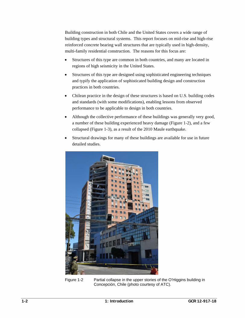
Building construction in both Chile and the United States covers a wide range of
building types and structural systems. This report focuses on mid-rise and high-rise
reinforced concrete bearing wall structures that are typically used in high-density,
multi-family residential construction. The reasons for this focus are:
Structures of this type are common in both countries, and many are located in
regions of high seismicity in the United States.
Structures of this type are designed using sophisticated engineering techniques
and typify the application of sophisticated building design and construction
practices in both countries.
Chilean practice in the design of these structures is based on U.S. building codes
and standards (with some modifications), enabling lessons from observed
performance to be applicable to design in both countries.
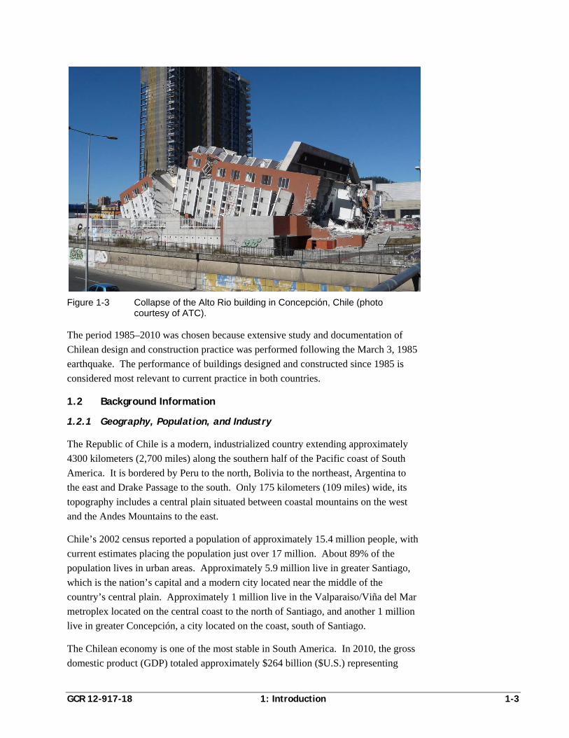
Although the collective performance of these buildings was generally very good,
a number of these building experienced heavy damage (Figure 1-2), and a few
collapsed (Figure 1-3), as a result of the 2010 Maule earthquake.
Structural drawings for many of these buildings are available for use in future
detailed studies.
Figure 1-2 Partial collapse in the upper stories of the O’Higgins building in
Concepción, Chile (photo courtesy of ATC).
GCR 12-917-18 1: Introduction 1-3
Figure 1-3 Collapse of the Alto Rio building in Concepción, Chile (photo courtesy of ATC).
The period 1985–2010 was chosen because extensive study and documentation of
Chilean design and construction practice was performed following the March 3, 1985
earthquake. The performance of buildings designed and constructed since 1985 is
considered most relevant to current practice in both countries.
1.2 Background Information
1.2.1 Geography, Population, and Industry
The Republic of Chile is a modern, industrialized country extending approximately
4300 kilometers (2,700 miles) along the southern half of the Pacific coast of South
America. It is bordered by Peru to the north, Bolivia to the northeast, Argentina to
the east and Drake Passage to the south. Only 175 kilometers (109 miles) wide, its
topography includes a central plain situated between coastal mountains on the west
and the Andes Mountains to the east.
Chile’s 2002 census reported a population of approximately 15.4 million people, with
current estimates placing the population just over 17 million. About 89% of the
population lives in urban areas. Approximately 5.9 million live in greater Santiago,
which is the nation’s capital and a modern city located near the middle of the
country’s central plain. Approximately 1 million live in the Valparaiso/Viña del Mar
metroplex located on the central coast to the north of Santiago, and another 1 million
live in greater Concepción, a city located on the coast, south of Santiago.
The Chilean economy is one of the most stable in South America. In 2010, the gross
domestic product (GDP) totaled approximately $264 billion ($U.S.) representing
1-4 1: Introduction GCR 12-917-18
approximately $15,300 ($U.S.) per capita. The GDP is composed of industry,
including mineral production such as copper (42%); agriculture, including beef, fish,
and wine (5%); and services/tourism (53%). [Data from The World Factbook (CIA,
2012).]
1.2.2 Regional Seismicity
The entire length of the Chile lies along a major subduction zone constituting the
southwest rim of the Pacific Ring of Fire. In this region, the Nazca Plate is being
subducted beneath the South American plate resulting in the uplift and volcanism of
the Andes Mountains and frequent, large-magnitude earthquakes. The two plates are
converging at approximately 7 meters (22 feet) per century. The United States
Geological Survey (USGS) lists approximately 25 major earthquakes that have
occurred within the country’s borders since 1730. More than 20 of these events are
estimated to have exceeded magnitude 7.0, eight have exceeded magnitude 8.0, and
two have exceeded magnitude 9.0.
Prior to the 2010 Maule earthquake, notable historic events in the vicinity included
the magnitude 7.5 earthquake in the Valparaiso region on July 8, 1971, and the
magnitude 7.8 earthquake offshore of Valparaiso on March 3, 1985, which affected
areas including Santiago, Valparaiso, and Viña del Mar. A magnitude 9.5 earthquake
occurred in the Valdivia region on May 22, 1960. It affected areas including
Concepción, and is regarded as the largest earthquake known to have occurred in the
20th Century. Together, these earthquakes produced strong ground shaking and
widespread damage in areas that were also affected by the 2010 Maule earthquake,
and resulted in a total of nearly 2000 fatalities. [Data from Historic World
Earthquakes (USGS, 2009).]
1.2.3 Construction Practice
Urban centers include many tall residential and commercial structures constructed of
reinforced concrete bearing wall systems. Low-rise residential, commercial, and
institutional construction is typically cast-in-place concrete or confined masonry
construction. The southern portion of the country, which has extensive forestation,
includes some wood frame construction. Structural steel construction is typically
limited to industrial facilities and long-span applications such as airport terminals and
stadiums. The Chilean economy experienced major growth during the period 1990–
2010 and, as a result, extensive building development occurred during this time
period.
In 1985, Chilean seismic design requirements governing the strength and stiffness of
buildings were similar to the requirements contained in Section 2312 of the Uniform
Building Code (ICBO, 1982) then in use in the United States. Design and detailing
provisions for concrete buildings were based on the German standard, DIN 1045,
GCR 12-917-18 1: Introduction 1-5
Concrete and Reinforced Concrete (DIN, 1953), and had not been substantially
changed for more than 20 years. As such, they did not contain modern seismic
detailing provisions intended to provide ductile behavior. Many Chilean engineers at
the time used ACI 318, Building Code Requirements for Reinforced Concrete (ACI,
1983) in lieu of requirements based on the German standard.
Although damage was extensive in the 1985 earthquake, taller concrete buildings in
Valparaiso and Viña del Mar generally performed well. Floor plates in these
buildings had dense shear wall patterns, and ratios of wall area to floor area were in
the range of 5% to 10% at a typical floor. These buildings generally lacked special
seismic detailing, but had enough strength and redundancy to perform well without
extensive damage. There were, of course, some exceptions. More detailed
information on building performance in the 1985 earthquake can be found in
Earthquake Spectra (EERI, 1986).
Following the 1985 earthquake, engineers updated Chilean seismic design provisions
based on contemporary Uniform Building Code requirements, and formally adopted
ACI 318 (with modifications) as the basis for detailing of concrete structures. In the
time leading up to the 2010 Maule earthquake, U.S. design concepts were embodied
in Chilean seismic design practice in NCh433.Of96, Earthquake Resistant Design of
Buildings (INN, 1996), and NCh430.Of2008, Reinforced Concrete Design and
Analysis Requirements (INN, 2008). As a result, the 2010 Maule earthquake
represents a unique opportunity to study the behavior of modern engineered
reinforced concrete construction, similar to that present in the United States, in
response to severe earthquake shaking.
1.3 The Maule Earthquake of February 27, 2010
The USGS reports that the Maule earthquake occurred at 3:34 am local time on
February 27, 2010, in the Bio-Bio/Maule region of Central Chile. The earthquake
had a moment magnitude, Mw, of 8.8, with an epicenter located at 35.909º South
latitude, 72.733º West longitude, or approximately 105 kilometers (65 miles) north-
northeast of Concepción, and 335 kilometers (210 miles) southwest of Santiago. The
focal depth was estimated to be 35 kilometers (22 miles). The approximate location
of the epicenter is shown in Figure 1-1.
The earthquake occurred along the subduction fault between the Nazca plate and the
South American plate. The fault ruptured largely offshore, spreading westward,
northward, and southward, extending 100 km (62 miles) in width and nearly 500 km
(300 miles) in length. The fault slip generated wide-spread, severe ground shaking
that was felt in cities including Santiago, Valparaiso, Viña del Mar, Talca,
Concepción, Temuco, and Valdivia. Deformations in the ocean floor generated a
tsunami that was severe in the cities of Constitución and Talcahuano near the fault-
1-6 1: Introduction GCR 12-917-18
rupture zone, and had measurable effects across the Pacific in portions of Mexico,
New Zealand, Japan, Canada, and the United States (including Hawaii, Alaska, and
the West Coast).
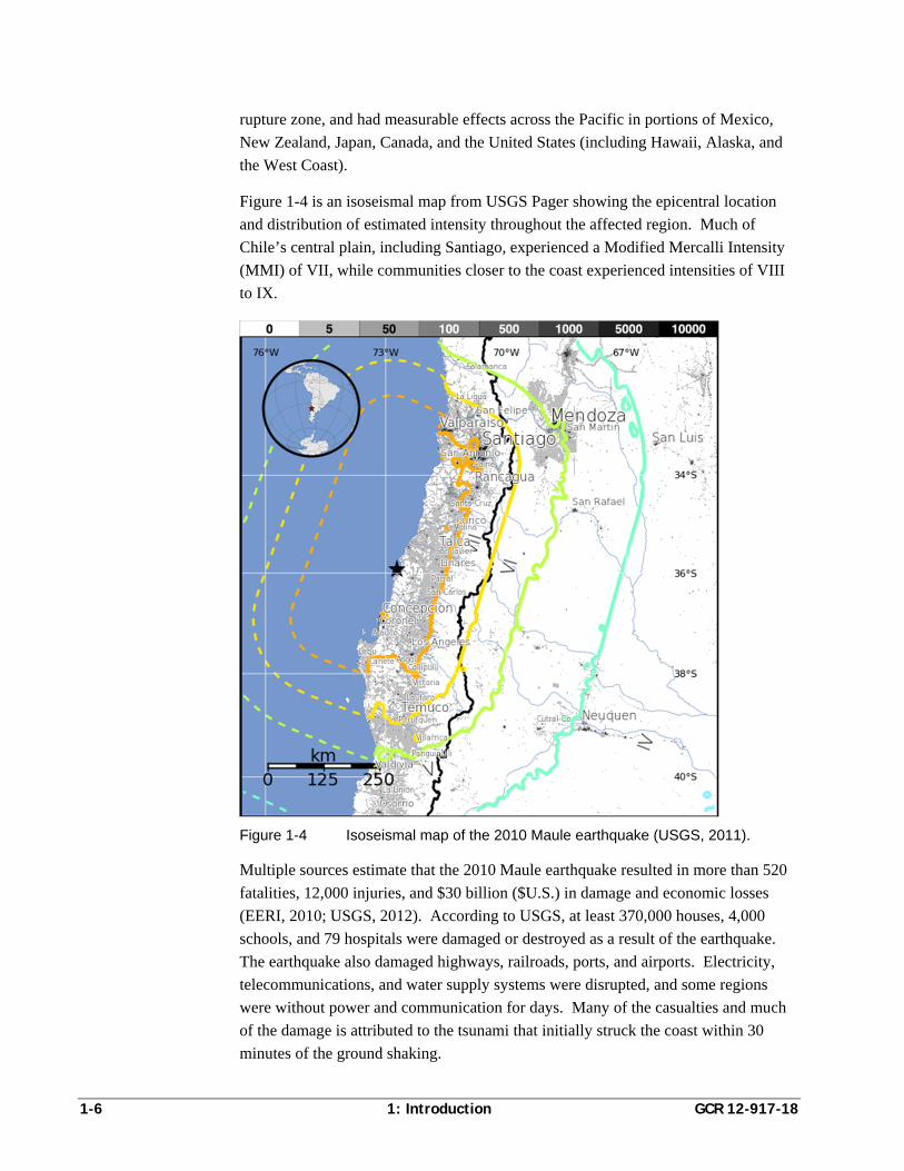
Figure 1-4 is an isoseismal map from USGS Pager showing the epicentral location
and distribution of estimated intensity throughout the affected region. Much of
Chile’s central plain, including Santiago, experienced a Modified Mercalli Intensity
(MMI) of VII, while communities closer to the coast experienced intensities of VIII
to IX.
Figure 1-4 Isoseismal map of the 2010 Maule earthquake (USGS, 2011).
Multiple sources estimate that the 2010 Maule earthquake resulted in more than 520
fatalities, 12,000 injuries, and $30 billion ($U.S.) in damage and economic losses
(EERI, 2010; USGS, 2012). According to USGS, at least 370,000 houses, 4,000
schools, and 79 hospitals were damaged or destroyed as a result of the earthquake.
The earthquake also damaged highways, railroads, ports, and airports. Electricity,
telecommunications, and water supply systems were disrupted, and some regions
were without power and communication for days. Many of the casualties and much
of the damage is attributed to the tsunami that initially struck the coast within 30
minutes of the ground shaking.
GCR 12-917-18 1: Introduction 1-7
Modern engineered buildings generally performed very well, with only a few cases of
collapse noted. EERI (2010) reported that approximately 50 multi-story reinforced
concrete buildings were severely damaged, and four experienced partial or total
collapse. Based on building surveys in the metropolitan region, the Engineers
Association of Chile (2010) estimated that approximately 2% of engineered buildings
experienced severe damage or collapse; 12% were damaged such that they were not
useable until repaired; and 86% were useable immediately following the earthquake.
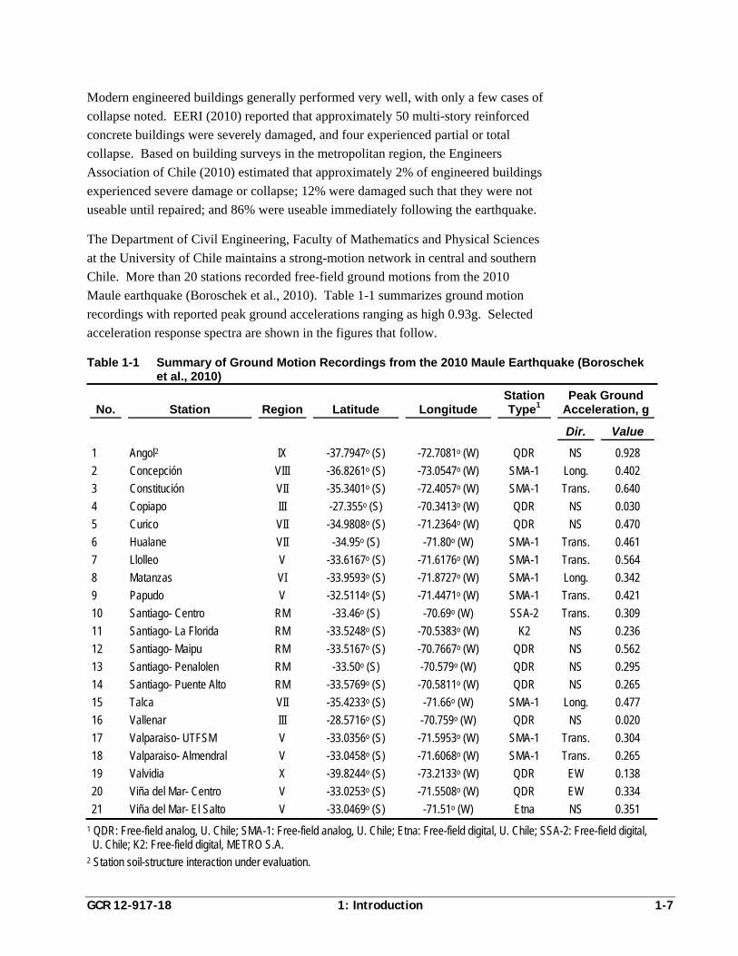
The Department of Civil Engineering, Faculty of Mathematics and Physical Sciences
at the University of Chile maintains a strong-motion network in central and southern
Chile. More than 20 stations recorded free-field ground motions from the 2010
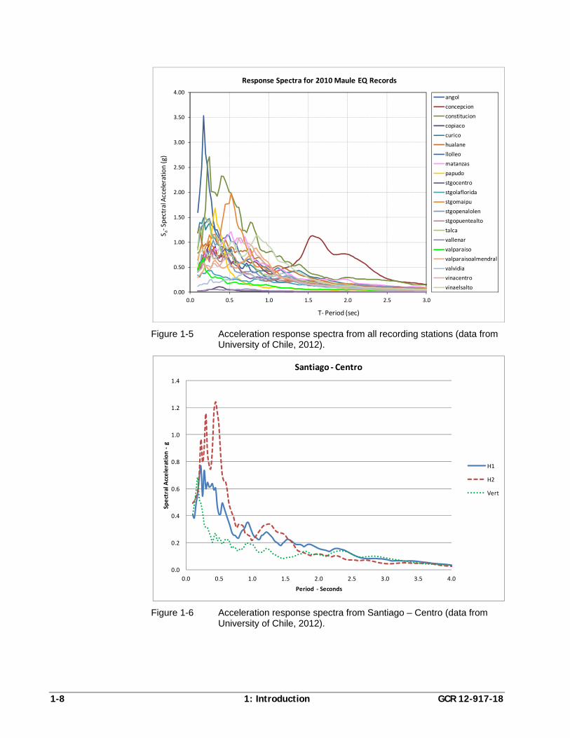
Maule earthquake (Boroschek et al., 2010). Table 1-1 summarizes ground motion
recordings with reported peak ground accelerations ranging as high 0.93g. Selected
acceleration response spectra are shown in the figures that follow.
Table 1-1 Summary of Ground Motion Recordings from the 2010 Maule Earthquake (Boroschek et al., 2010)
No. Station Region Latitude Longitude Station Type1
Peak Ground Acceleration, g
Dir. Value
1 Angol2 IX -37.7947o (S) -72.7081o (W) QDR NS 0.928
2 Concepción VIII -36.8261o (S) -73.0547o (W) SMA-1 Long. 0.402
3 Constitución VII -35.3401o (S) -72.4057o (W) SMA-1 Trans. 0.640
4 Copiapo III -27.355o (S) -70.3413o (W) QDR NS 0.030
5 Curico VII -34.9808o (S) -71.2364o (W) QDR NS 0.470
6 Hualane VII -34.95o (S) -71.80o (W) SMA-1 Trans. 0.461
7 Llolleo V -33.6167o (S) -71.6176o (W) SMA-1 Trans. 0.564
8 Matanzas VI -33.9593o (S) -71.8727o (W) SMA-1 Long. 0.342
9 Papudo V -32.5114o (S) -71.4471o (W) SMA-1 Trans. 0.421
10 Santiago- Centro RM -33.46o (S) -70.69o (W) SSA-2 Trans. 0.309
11 Santiago- La Florida RM -33.5248o (S) -70.5383o (W) K2 NS 0.236
12 Santiago- Maipu RM -33.5167o (S) -70.7667o (W) QDR NS 0.562
13 Santiago- Penalolen RM -33.50o (S) -70.579o (W) QDR NS 0.295
14 Santiago- Puente Alto RM -33.5769o (S) -70.5811o (W) QDR NS 0.265
15 Talca VII -35.4233o (S) -71.66o (W) SMA-1 Long. 0.477
16 Vallenar III -28.5716o (S) -70.759o (W) QDR NS 0.020
17 Valparaiso- UTFSM V -33.0356o (S) -71.5953o (W) SMA-1 Trans. 0.304
18 Valparaiso- Almendral V -33.0458o (S) -71.6068o (W) SMA-1 Trans. 0.265
19 Valvidia X -39.8244o (S) -73.2133o (W) QDR EW 0.138
20 Viña del Mar- Centro V -33.0253o (S) -71.5508o (W) QDR EW 0.334
21 Viña del Mar- El Salto V -33.0469o (S) -71.51o (W) Etna NS 0.351
1 QDR: Free-field analog, U. Chile; SMA-1: Free-field analog, U. Chile; Etna: Free-field digital, U. Chile; SSA-2: Free-field digital, U. Chile; K2: Free-field digital, METRO S.A.
2 Station soil-structure interaction under evaluation.
1-8 1: Introduction GCR 12-917-18
Figure 1-5 Acceleration response spectra from all recording stations (data from University of Chile, 2012).
Figure 1-6 Acceleration response spectra from Santiago – Centro (data from
University of Chile, 2012).
0.00
0.50
1.00
1.50
2.00
2.50
3.00
3.50
4.00
0.0 0.5 1.0 1.5 2.0 2.5 3.0
S a‐Spectral Acceleration (g)
T‐ Period (sec)
Response Spectra for 2010 Maule EQ Records
angol
concepcion
constitucion
copiaco
curico
hualane
llolleo
matanzas
papudo
stgocentro
stgolaflorida
stgomaipu
stgopenalolen
stgopuentealto
talca
vallenar
valparaiso
valparaisoalmendral
valvidia
vinacentro
vinaelsalto
0.0
0.2
0.4
0.6
0.8
1.0
1.2
1.4
0.0 0.5 1.0 1.5 2.0 2.5 3.0 3.5 4.0
Spectral A
cceleration ‐g
Period ‐ Seconds
Santiago ‐ Centro
H1
H2
Vert
GCR 12-917-18 1: Introduction 1-9
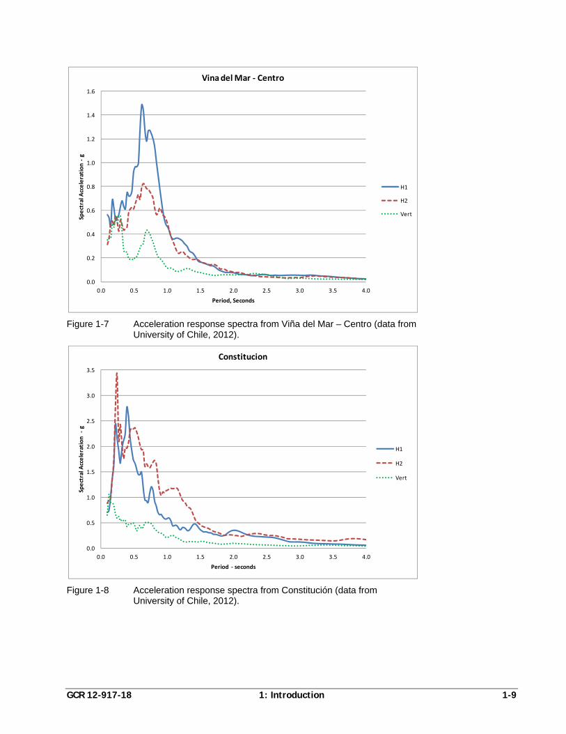
Figure 1-7 Acceleration response spectra from Viña del Mar – Centro (data from
University of Chile, 2012).
Figure 1-8 Acceleration response spectra from Constitución (data from
University of Chile, 2012).
0.0
0.2
0.4
0.6
0.8
1.0
1.2
1.4
1.6
0.0 0.5 1.0 1.5 2.0 2.5 3.0 3.5 4.0
Spectral A
cceleration ‐g
Period, Seconds
Vina del Mar ‐ Centro
H1
H2
Vert
0.0
0.5
1.0
1.5
2.0
2.5
3.0
3.5
0.0 0.5 1.0 1.5 2.0 2.5 3.0 3.5 4.0
Spectral A
cceleration ‐g
Period ‐ seconds
Constitucion
H1
H2
Vert
1-10 1: Introduction GCR 12-917-18
1.4 Report Organization and Content
This report summarizes building code requirements and design and construction
practices in effect in Chile during the period 1985–2010, presents a similar summary
for U.S. codes and practices, and documents the similarities and differences between
the two.
Chapter 2 provides an overview of Chilean design practice during the period 1985–
2010, reviews operative codes and standards and their detailed requirements, and
discusses the typical configuration of mid-rise and high-rise concrete residential
construction during this era.
Chapter 3 describes the evolution of U.S. seismic design provisions, provides an
overview of past and present U.S. codes and design practice, and summarizes U.S.
reinforced concrete design provisions that are not included in Chilean practice.
Chapter 4 presents a side-by-side comparison of design requirements in the United
States and Chile, identifies similarities, and contrasts differences.
Chapter 5 compares design practice in the United States and Chile through a
comparative evaluation considering both Chilean and U.S. design provisions applied
to a typical Chilean building configuration and a similarly sized U.S. building
configuration designed in accordance with U.S. practice.
GCR 12-917-18 2: Chilean Practice 2-1
Chapter 2
Chilean Practice
2.1 Operative Codes
Building codes in Chile are developed and published by the Instituto Nacional de
Normalización (National Standards Institute), or INN, which is the Chilean member
organization of the International Organization for Standardization (ISO). INN
publishes design criteria in the form of individual Normas (Standards). Two primary
standards govern seismic-resistant design of reinforced concrete structures in Chile:
NCh433 – Earthquake Resistant Design of Buildings
NCh430 – Reinforced Concrete Design and Analysis Requirements
NCh433 encompasses requirements for calculating seismic loads for design of
structures, comparable to Chapters 11 through 22 of ASCE/SEI 7, Minimum Design
Loads for Buildings and Other Structures, in the United States. NCh430 sets the
criteria for design and detailing of reinforced concrete structures, comparable to
ACI 318, Building Code Requirements for Structural Concrete, in the United States.
2.1.1 NCh433 Loading Standard
Initial development of the NCh433 Chilean loading standard occurred in 1986 with
the appointment of the Comité Coordinador de Normas Sismorresistentes
(Committee on Standards for Seismic Resistance) by the INN. The initial document
was submitted for public review in July 1989. After review and comment, it was
adopted in 1993. Following publication as NCh433.Of93, INN established a series of
working groups to review the use of the standard in practice, and to make
recommendations for future updates. In 1996, a slightly modified version of the
standard was published as NCh433.Of96, Earthquake Resistant Design of Buildings
(INN, 1996), which was the version in effect at the time of the 2010 Maule
earthquake.
NCh433.Of96 is closely related to seismic design requirements contained in various
editions of the Uniform Building Code, which were used throughout the Western
United States during the period 1988–2000. Both NCh433 and the Uniform Building
Code of that era (ICBO, 1994) utilized seismic design requirements based on
ATC 3-06, Tentative Provisions for the Development of Seismic Regulations for
Buildings (ATC, 1978).
2-2 2: Chilean Practice GCR 12-917-18
The requirements in NCh433.Of96 include a number of revisions to the procedures
contained in the Uniform Building Code from which they were derived. Significant
differences include:
Adoption of seismic zonation maps particular to the seismic hazard in Chile.
Adoption of site factors and spectral shapes appropriate to the characteristics of
earthquake shaking associated with large magnitude subduction zone
earthquakes.
Specification of structural systems and corresponding design parameters
appropriate to Chilean construction practices.
In the United States, the ATC 3-06 report served as the basis for seismic design
provisions known as the NEHRP Recommended Provisions for the Development of
Seismic Regulations for New Buildings (BSSC, 1985). Since their initial publication,
the NEHRP Provisions have been further developed and continuously updated on a
3-year cycle. The International Building Code (ICC, 2000), successor to the Uniform
Building Code, adopted seismic design criteria based on the 1997 edition of the
NEHRP Provisions (BSSC, 1998), and beginning in 2006, adopted seismic design
requirements by reference to ASCE/SEI 7-05, Minimum Design Loads for Buildings
and Other Structures (ASCE, 2006). Important differences that have evolved between
the seismic design provisions contained in the present International Building Code
and those contained in the earlier Uniform Building Code include:
Use of a revised definition of design earthquake shaking.
Replacement of the concept of seismic zones with Seismic Design Categories
based on consideration of site seismic hazard and building occupancy.
Use of revised design parameters, including the response modification coefficient
(R factor), the system overstrength factor (), and deflection amplification
factor (Cd).
Addition of requirements to consider redundancy of the seismic force-resisting
system in determining seismic loads.
An expanded list of permissible structural systems.
Specification of system detailing requirements independent of seismic zone.
Although the starting point was the same, the details of present seismic design
loading requirements in each country have diverged as a result of the above-noted
differences in the evolution and modification of Uniform Building Code
requirements. NCh433 requirements are described in more detail in Section 2.3,
contemporary U.S. requirements are described in Chapter 3, and similarities and
differences are compared in Chapter 4.
GCR 12-917-18 2: Chilean Practice 2-3
2.1.2 NCh430 Concrete Design Standard
For many years, the Chilean standard for reinforced concrete was NCh429.Of1957,
Reinforced Concrete – Part I, and NCh430.Of1961, Reinforced Concrete – Part II,
based on the German standard, DIN 1045, Concrete and Reinforced Concrete (DIN,
1953). These provisions were not substantially changed for more than 20 years until
1983, when engineers selected ACI 318-83, Building Code Requirements for
Reinforced Concrete (ACI, 1983) as the new Chilean standard for reinforced concrete
design.
In 1993, after many years of unofficial use, the Chilean loading standard
NCh433.Of93 formally adopted ACI 318-89 for the design of reinforced concrete
structures. In 1996, the updated loading standard, NCh433.Of96, updated the
reference to ACI 318-95 as the basis for reinforced concrete construction. Based on
Chilean experience using ACI 318, it became apparent that additional modifications
were necessary to better adapt the requirements to Chilean practice. These
modifications are contained in NCh430.Of2008, Reinforced Concrete Design and
Analysis Requirements (INN, 2008), which adopted ACI 318-05 as its fundamental
basis, and annotated Chilean exceptions. This version was in effect for design of
reinforced concrete structures at the time of the 2010 Maule earthquake.
Important exceptions to ACI 318-05 contained in NCh430.Of2008 include:
Omission of requirements for confined boundary elements in reinforced concrete
shear walls.
Permissive use of the detailing requirements for Intermediate Moment Frames
(ACI 318, Section 21.12) when primary lateral resistance is provided by walls
with the strength to resist 75% of the specified seismic design forces, even in
regions of high seismic risk in which special detailing criteria would typically
apply.
Replacement of references to ASTM material standards with appropriate
references to Chilean Normas.
Permissive use of concrete cubes rather than cylinders for testing concrete
strength in production.
Adoption of reduced cover requirements relative U.S. requirements for protection
of reinforcement in various exposure conditions.
Use of gross section properties, neglecting reinforcement, when calculating the
distribution of internal forces within a structure, except in cases where P-delta
stability effects are significant.
Modification of load factors in load combinations, utilizing a factor of 1.4 on
earthquake loads in lieu of 1.0, as specified in ACI 318.
2-4 2: Chilean Practice GCR 12-917-18
Modification of requirements for tension splices in reinforcement.
Reasons for these exceptions are based on differences in Chilean earthquake
experience and evolution from historic practices. For example, concrete cubes are
used for strength testing in lieu of concrete cylinders because Chilean practice
evolved from European practices embodied in DIN 1045, which specified the use of
cubes. When ACI 318 was adopted, Chile maintained this practice because Chilean
testing agencies were familiar with the use of cubes. In recent years, concrete quality
assurance testing for larger buildings has sometimes adopted the use of cylinders, as
practiced in the United States.
The use of reduced concrete cover in Chile is also a result of historic precedent and
practice embodied in DIN 1045. Past experience in Chile has resulted in few
problems with corrosion of reinforcement in buildings, so when ACI 318 was
adopted, historic cover requirements were maintained.
The permissive use of Intermediate Moment Frame detailing in buildings with
primary lateral resistance provided by shear walls is based on judgment. Chilean
engineers expect these buildings to be very stiff, that significant ductility demands on
the frame elements in such systems will be unlikely, and that ductile detailing
associated with Special Moment Frames will not be necessary.
Exclusion of provisions for confined boundary elements in reinforced concrete shear
walls is a direct result of studies of buildings without confined boundaries that
performed well in the 1985 earthquake. Investigations supporting this conclusion
have been documented in reports by U.S. researchers, including Wood (1991) and
Wood et al. (1987).
2.2 Typical Chilean Design Practice
Although building codes in the United States and Chile are similar, the typical
configuration of structural systems in buildings of similar size and occupancy tend to
be quite different. This can be attributed to several factors, including:
The portion of the total construction cost associated with labor in Chile is
significantly smaller than in the United States.
Structural engineers in Chile are typically employed directly by the project
developer, while structural engineers in the United States typically work as a
subconsultant to the architect.
Typical building configurations in use in Chile have generally provided good
performance in past large-magnitude earthquakes.
The relatively low cost of construction labor relative to materials in Chile favors the
use of distributed structural systems in which many elements provide lateral
resistance. In contrast, the relatively high cost of labor in the United States drives
GCR 12-917-18 2: Chilean Practice 2-5
engineers towards designs that minimize the number of elements, reducing the
amount of redundancy provided in structural systems. In Chile, buildings are
typically designed using shorter spans, more vertical load resisting elements, and
smaller structural elements with lighter reinforcement than comparable buildings in
the United States.
Low-rise construction has traditionally consisted of masonry or concrete bearing wall
buildings with relatively short spans and many walls. As building practices evolved,
and mid-rise and high-rise construction became more prevalent, engineers continued
these same practices, employing relatively short spans in floor systems and providing
many load-bearing walls for both gravity and seismic force resistance. As a rule of
thumb, Chilean engineers generally knew that they needed to provide shear walls
with a cross sectional area equal to approximately 1% of the gross floor area above
the first story. Based on past experience, they believed that special ductile detailing
of these walls was not necessary. Building performance in past earthquakes,
including events in 1971 and 1985, generally confirmed that these practices provided
good performance.
The direct reporting relationship between the structural engineer and the developer
gives Chilean engineers the ability to advocate sound structural design practice and
caution against the risks associated with compromising structural design for the sake
of architectural appearance. This relationship has contributed to the ongoing ability
of Chilean engineers to produce designs with distributed seismic force-resisting
elements and high levels of redundancy. This practice is in stark contrast to U.S.
practice in which many engineers feel constrained in their ability to influence
architectural design to accommodate favorable structural configurations. Even under
this advantageous teaming relationship, however, Chilean engineers have reported
that pressure to reduce system redundancy and consider more irregular configurations
is increasing.
Typical Chilean mid-rise and high-rise construction favors reinforced concrete
bearing wall construction. Concrete strengths typically range from 20 MPa (3 ksi) to
30 MPa (4.5 ksi). Reinforcing steel typically conforms to grade A630-420H in
NCh204, Reinforcing Steel – Hot-Rolled Rebar for Reinforced Concrete (INN, 2006),
with a yield strength of 420 MPa (60 ksi) and ultimate strength of 630 MPa (90 ksi).
Mid-rise and high-rise building configurations are mostly rectangular in plan, though
more inventive forms can be found. High-rise construction often has extensive
glazing with few exterior walls. Setbacks in building elevation occur, but are
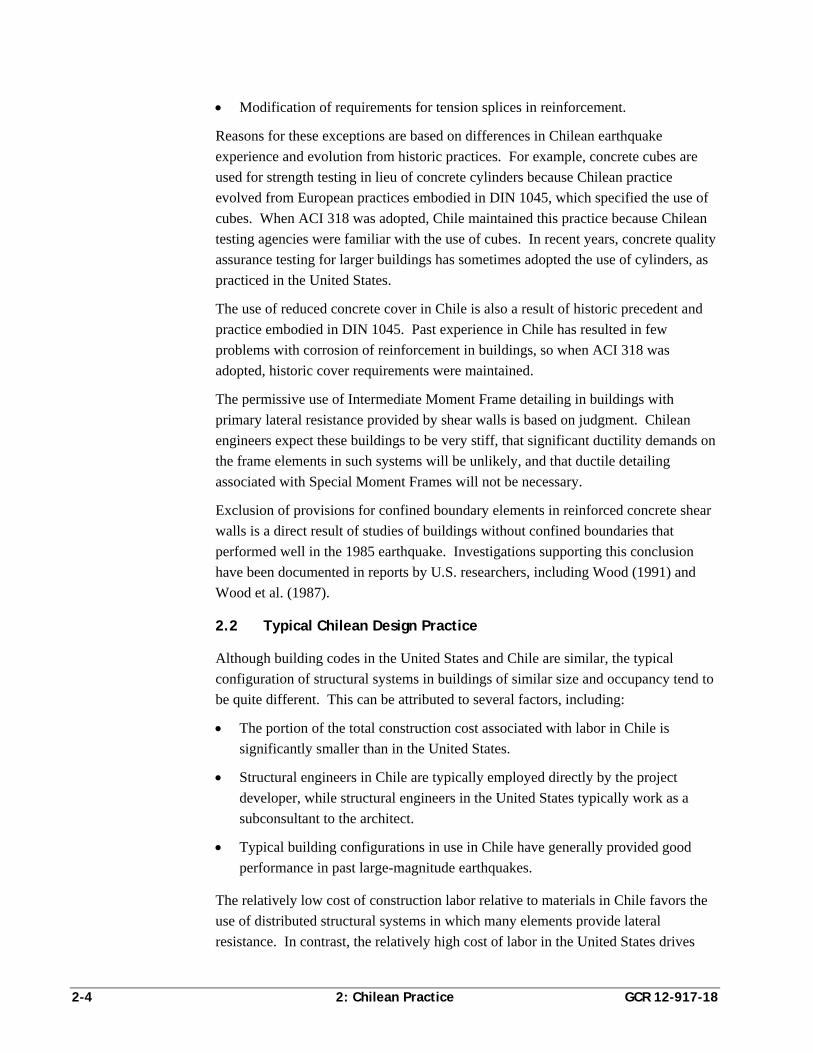
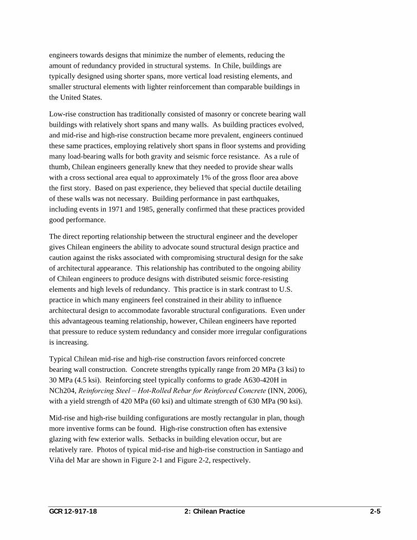
relatively rare. Photos of typical mid-rise and high-rise construction in Santiago and
Viña del Mar are shown in Figure 2-1 and Figure 2-2, respectively.
2-6 2: Chilean Practice GCR 12-917-18
Figure 2-1 Typical mid-rise and high-rise buildings in Santiago (photo
courtesy of Rene Lagos).
Figure 2-2 Typical mid-rise and high-rise buildings in Viña del Mar (photo courtesy of ASCE).
A sample floor plan for a typical Chilean high-rise residential building is shown in
Figure 2-3. A cross-section of a typical mid-rise Chilean residential building is
shown in Figure 2-4.
GCR 12-917-18 2: Chilean Practice 2-7
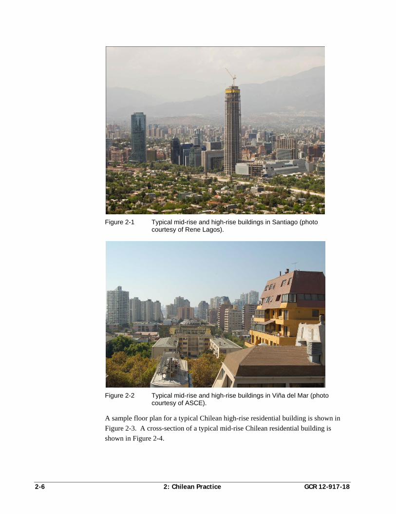
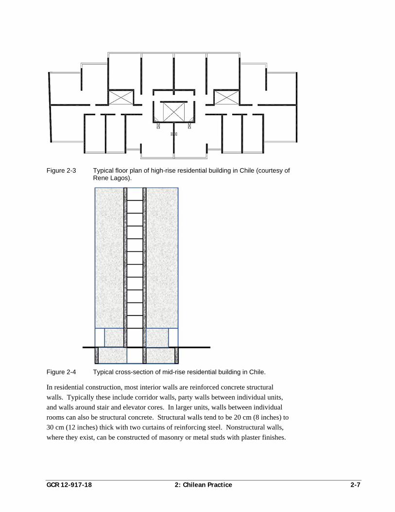
Figure 2-3 Typical floor plan of high-rise residential building in Chile (courtesy of Rene Lagos).
Figure 2-4 Typical cross-section of mid-rise residential building in Chile.
In residential construction, most interior walls are reinforced concrete structural
walls. Typically these include corridor walls, party walls between individual units,
and walls around stair and elevator cores. In larger units, walls between individual
rooms can also be structural concrete. Structural walls tend to be 20 cm (8 inches) to
30 cm (12 inches) thick with two curtains of reinforcing steel. Nonstructural walls,
where they exist, can be constructed of masonry or metal studs with plaster finishes.

2-8 2: Chilean Practice GCR 12-917-18
Floors typically consist of flat slab construction with spans on the order of 6 to 8
meters. Floor heights are typically on the order of 3 meters or less. Doorways in
structural walls occupy most of the story height leaving little room for coupling
beams. Typically, a shallow lintel with nominal reinforcement spans over such
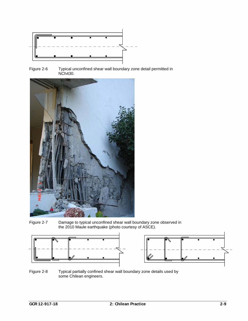
doorways, as shown in Figure 2-5.
Figure 2-5 Shallow lintel showing nominal reinforcement and lack of confinement in a residential building that was damaged in the 2010 Maule earthquake (photo courtesy of ASCE).
Walls are typically reinforced with two curtains of small diameter bars (10 to 14 mm)
arranged at uniform vertical and horizontal spacing. Engineers cluster larger
diameter bars ranging from 20 mm (No. 7) to 32 mm (No. 11) at the ends of walls to
resist computed flexural demands. Horizontal bars typically terminate with a 90º
hook around the outer layer of boundary bars, as shown in Figure 2-6. In the 2010
Maule earthquake, this detailing practice resulted in the damage shown in Figure 2-7.
Although unconfined boundary elements are permitted in NCh430, not all Chilean
engineers have universally implemented this in practice. Some engineers report that
partial confinement of boundary zones is routinely provided using cross ties with
alternating 90º and 135º hooks on every other vertical bar, as illustrated in Figure 2-8.
The area of cross ties provided is generally not sufficient to fully satisfy ACI 318
criteria for confinement, but it is reported that buildings incorporating this type of
detailing did not experience the type of damage shown in Figure 2-7.
GCR 12-917-18 2: Chilean Practice 2-9
Figure 2-6 Typical unconfined shear wall boundary zone detail permitted in
NCh430.
Figure 2-7 Damage to typical unconfined shear wall boundary zone observed in
the 2010 Maule earthquake (photo courtesy of ASCE).
Figure 2-8 Typical partially confined shear wall boundary zone details used by
some Chilean engineers.
2-10 2: Chilean Practice GCR 12-917-18
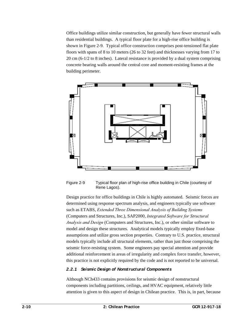
Office buildings utilize similar construction, but generally have fewer structural walls
than residential buildings. A typical floor plate for a high-rise office building is
shown in Figure 2-9. Typical office construction comprises post-tensioned flat plate
floors with spans of 8 to 10 meters (26 to 32 feet) and thicknesses varying from 17 to
20 cm (6-1/2 to 8 inches). Lateral resistance is provided by a dual system comprising
concrete bearing walls around the central core and moment-resisting frames at the
building perimeter.
Figure 2-9 Typical floor plan of high-rise office building in Chile (courtesy of Rene Lagos).
Design practice for office buildings in Chile is highly automated. Seismic forces are
determined using response spectrum analysis, and engineers typically use software
such as ETABS, Extended Three Dimensional Analysis of Building Systems
(Computers and Structures, Inc.), SAP2000, Integrated Software for Structural
Analysis and Design (Computers and Structures, Inc.), or other similar software to
model and design these structures. Analytical models typically employ fixed-base
assumptions and utilize gross section properties. Contrary to U.S. practice, structural
models typically include all structural elements, rather than just those comprising the
seismic force-resisting system. Some engineers pay special attention and provide
additional reinforcement in areas of irregularity and complex force transfer, however,
this practice is not explicitly required by the code and is not reported to be universal.
2.2.1 Seismic Design of Nonstructural Components
Although NCh433 contains provisions for seismic design of nonstructural
components including partitions, ceilings, and HVAC equipment, relatively little
attention is given to this aspect of design in Chilean practice. This is, in part, because
GCR 12-917-18 2: Chilean Practice 2-11
structural engineers have not perceived that design of bracing and anchorage for
nonstructural components is within their provenance. Other design professionals are
not familiar enough with seismic design requirements to be concerned about bracing
and anchorage of nonstructural components, and therefore, this aspect of seismic
design has been frequently neglected.
2.3 Chilean Design Criteria
2.3.1 Seismic Zonation
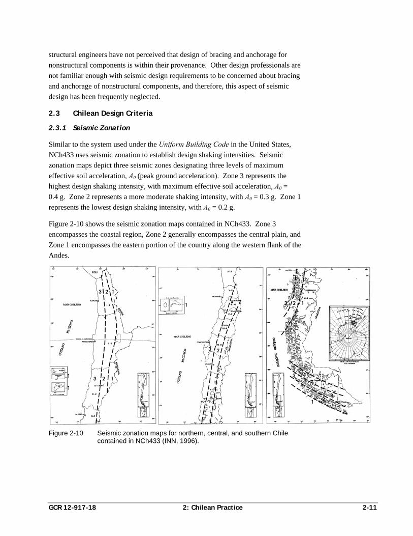
Similar to the system used under the Uniform Building Code in the United States,
NCh433 uses seismic zonation to establish design shaking intensities. Seismic
zonation maps depict three seismic zones designating three levels of maximum
effective soil acceleration, A0 (peak ground acceleration). Zone 3 represents the
highest design shaking intensity, with maximum effective soil acceleration, A0 =
0.4 g. Zone 2 represents a more moderate shaking intensity, with A0 = 0.3 g. Zone 1
represents the lowest design shaking intensity, with A0 = 0.2 g.
Figure 2-10 shows the seismic zonation maps contained in NCh433. Zone 3
encompasses the coastal region, Zone 2 generally encompasses the central plain, and
Zone 1 encompasses the eastern portion of the country along the western flank of the
Andes.
Figure 2-10 Seismic zonation maps for northern, central, and southern Chile contained in NCh433 (INN, 1996).
2-12 2: Chilean Practice GCR 12-917-18
2.3.2 Site Class
NCh433 accounts for site effects on ground shaking intensity through assignment of
spectral modification coefficients based on soil type (site class). Four soil types are
defined:
Soil Type I. Sites with near-surface rock having shear wave velocities of
900 m/s or greater, or uniaxial compressive strengths of 10 MPa and a fracture
measure indicative of competent material defined by a specified maximum value
of fracture lengths within a standard specimen. Rock is considered near-surface
if the top of the rock is within 20 m of the surface with an overburden of firm
soil, or within 10 m of the surface with an overburden of soil that is not
considered firm.
Soil Type II. Firm soil sites including: (a) soils with shear wave velocities of
400 m/s or greater in the upper 10 m; (b) dense gravel with a unit weight equal to
or greater than 20 kN/m3, more than 95% of maximum compaction determined
by the Modified Proctor Compaction Test, or relative density of 75% or more;
(c) dense sand with a relative density greater than 75%, a penetration resistance
index, N, of 40 or greater, or more than 95% of maximum compaction
determined by the Modified Proctor Compaction Test; or (d) stiff cohesive soils
with undrained shear strength equal to or greater than 0.10 MPa (compressive
strength equal to or greater than 0.20 MPa), in specimens without fissures.
Soil Type III. Soil sites including: (a) unsaturated sand with relative densities
between 50% and 75%, a penetration resistance index, N, of more than 20;
(b) unsaturated gravel or sand with compaction less than 95% of maximum
determined by the Modified Proctor Compaction Test; (c) cohesive soils with
undrained shear strength in the range of 0.025 MPa to 0.10 MPa; or (d) saturated
sands with penetration resistance index, N, in the range of 20 to 40.
Soil Type IV. Saturated cohesive soils with undrained shear strength equal to or
less than 0.025 MPa (compressive strength equal to or less than 0.050 MPa).
Chilean engineers report that although site class descriptions include ranges of shear
wave velocity, this parameter is seldom actually used in determining site class. More
commonly, blow count, Modified Proctor Compaction, and shear strength are used.
In some cases, a less formal system has been used in which sites with near surface
rock are designated as Site Class I; those with gravel are designated as Site Class II;
and those with sand are designated as Site Class III. It is reported that some
structures on sandy soils classified in this manner did not perform well, and more
rigorous consideration of the classification of soil is now under consideration.
GCR 12-917-18 2: Chilean Practice 2-13
Spectral shape factors are specified for each of these site classes. Liquefiable soils
and soils subject to seismic-induced collapse require special study to determine site
response and spectral characteristics.
2.3.3 Occupancy Categories
NCh433 considers occupancy in the determination of seismic design forces. Four
building occupancy categories are defined based on importance, occupancy, and
failure risk:
Category A. Buildings intended to remain in operation following earthquakes,
such as government buildings, police stations, power plants, and telephone
switch centers.
Category B. Buildings housing high-value contents, such as museums; high-
occupancy buildings, including stadiums housing more than 2000 persons, or
single rooms housing assemblies of 100 or more; schools and nurseries; prisons;
and large retail stores or complexes.
Category C. Ordinary buildings not classified as A or B.
Category D. Buildings not normally used for human habitation.
Seismic design forces for Category A and Category B buildings are taken as 120% of
the forces for category C (ordinary) buildings, while design forces for Category D
buildings are taken as 60% of those for Category C (ordinary) buildings.
2.3.4 Load Combinations
Separate series of Allowable Stress Design (ASD) and Load and Resistance Factor
Design (LRFD) load combinations are specified. ASD combinations include:
D L E
D E
where D is defined as permanent load (dead load in the United States); L is live load;
and, E is the load due to horizontal earthquake shaking. A 33.3% increase in
allowable stresses is permitted for ASD load combinations including seismic loading.
LRFD combinations include:
1.4 D L E
0.9 1.4D E
where all terms are as previously defined.
2.3.5 Structural Systems
NCh433 recognizes three general types of seismic force-resisting systems:
Shear wall and other braced systems
2-14 2: Chilean Practice GCR 12-917-18
Moment-resisting space frame systems
Dual systems containing a combination of the above two systems
These systems are further classified according to the material of construction.
Structural response modification factors, designated as R or R0, are assigned based on
system type and used to determine the design base shear.
2.3.6 Analysis Procedures
NCh433 recognizes two analytical procedures for determining seismic design forces:
a static procedure and a modal response spectrum procedure. The modal response
spectrum procedure can be used in the design of any building. The static analysis
procedure is limited to the following applications:
Ordinary structures (Category C), or uninhabited structures (Category D), located
in Seismic Zone 1.
Structures not exceeding 5 stories or 20 m in height.
Structures with heights between 6 and 15 stories that meet certain measures of
regularity. For these structures, the design base shear cannot be taken as less
than the minimum base shear permissible for modal analysis.
Although the static analysis procedure is permitted for some buildings as tall as 15
stories, it is never actually used for such structures. Instead, the modal response
spectrum procedure is typically used for design of structures of significant size.
Regardless of analysis procedure, seismic forces are required to be distributed to the
various seismic force-resisting elements using a three-dimensional model having two
translational and one rotational degree of freedom at each level. Buildings must be
analyzed for seismic forces applied in each of two, approximately orthogonal
directions.
Cantilevered elements including marquees, balconies, and similar elements must be
designed for an effective vertical earthquake force equal to 30% of the dead and live
loads. This is accomplished by simply increasing the design dead and live loads by
30% for these elements.
The permissible story drift ratio in each direction, measured at the center of mass of
the floor plate, cannot exceed 0.002. At any point on the diaphragm, the story drift
ratio cannot exceed the value at the center of mass by more than 0.001.
2.3.7 Static Analysis
The total seismic base shear in each direction, Q0, is determined from the formula:
0Q CIP (NCh433 Eq. 6-1)
GCR 12-917-18 2: Chilean Practice 2-15
where, C is the seismic (base shear) coefficient; I, is an occupancy importance factor
taken as 1.2 for Categories A and B, 1.0 for Category C, and 0.6 for Category D; and
P is the effective seismic weight of the building above the base, taken as the weight
of permanent elements plus a specified fraction of live loads, except roof live load.
For typical public and private buildings, 25% of the specified live load is used in
computing the seismic weight. In storage occupancies at least 50% of specified live
load must be included in the seismic weight.
The seismic coefficient, C, is obtained from the equation:
0*
2.75
g
nA T
CR T
(NCh433 Eq. 6-2)
where A0 is the maximum effective soil acceleration determined by seismic zone; g is
the acceleration due to gravity; R is a system-dependent structural response
modification coefficient; T′ is a characteristic site period that depends on soil type, T*
is the period of the mode with the highest translational mass participation in the
direction under consideration; and n is a coefficient dependent on soil type.
For linear static analysis, values of the response modification coefficient, R, range
from 7, for moment-resisting frames and certain shear wall and braced frame
systems, to 2 for undefined systems. The value of T′ varies from 0.2 seconds on rock
(Class I) sites to 1.35 seconds on saturated clay sites. The exponent n varies from a
value of 1.0 on rock sites to a value of 1.8 on saturated clay sites.
The value of C cannot be taken less than A0/6g, and need not be taken greater than a
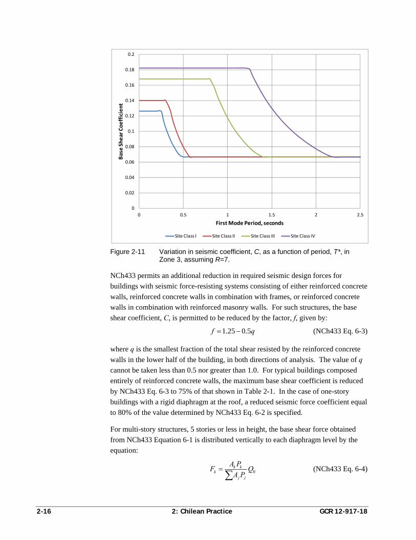
maximum value, correlated with the value of R, listed in Table 2-1 below. Figure
2-11 plots the variation in the base shear coefficient, C, for ductile a structure with a
response modification coefficient R = 7, in Zone 3, for varying structural period T*,
and for each of the four defined soil types (site classes).
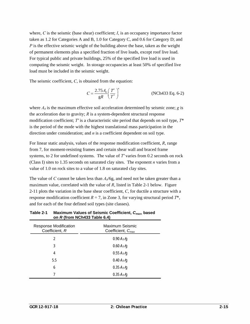
Table 2-1 Maximum Values of Seismic Coefficient, Cmax, based on R (from NCh433 Table 6.4)
Response Modification Coefficient, R
Maximum Seismic Coefficient, Cmax
2 0.90 A0 /g
3 0.60 A0 /g
4 0.55 A0 /g
5.5 0.40 A0 /g
6 0.35 A0 /g
7 0.35 A0 /g
2-16 2: Chilean Practice GCR 12-917-18
Figure 2-11 Variation in seismic coefficient, C, as a function of period, T*, in Zone 3, assuming R=7.
NCh433 permits an additional reduction in required seismic design forces for
buildings with seismic force-resisting systems consisting of either reinforced concrete
walls, reinforced concrete walls in combination with frames, or reinforced concrete
walls in combination with reinforced masonry walls. For such structures, the base
shear coefficient, C, is permitted to be reduced by the factor, f, given by:
1.25 0.5f q (NCh433 Eq. 6-3)
where q is the smallest fraction of the total shear resisted by the reinforced concrete
walls in the lower half of the building, in both directions of analysis. The value of q
cannot be taken less than 0.5 nor greater than 1.0. For typical buildings composed
entirely of reinforced concrete walls, the maximum base shear coefficient is reduced
by NCh433 Eq. 6-3 to 75% of that shown in Table 2-1. In the case of one-story
buildings with a rigid diaphragm at the roof, a reduced seismic force coefficient equal
to 80% of the value determined by NCh433 Eq. 6-2 is specified.
For multi-story structures, 5 stories or less in height, the base shear force obtained
from NCh433 Equation 6-1 is distributed vertically to each diaphragm level by the
equation:
0k k
kj j
A PF Q
A P
(NCh433 Eq. 6-4)
0
0.02
0.04
0.06
0.08
0.1
0.12
0.14
0.16
0.18
0.2
0 0.5 1 1.5 2 2.5
Base Shear Coefficient
First Mode Period, seconds
Site Class I Site Class II Site Class III Site Class IV
GCR 12-917-18 2: Chilean Practice 2-17
where, Q0 is the total base shear force, Pk and Pj are the effective seismic weight at
levels k and j, respectively, and the coefficients Ak and Aj are defined by the equation:
11 1k kk
Z ZA
H H (NCh433 Eq. 6-5)
where Zk and Zk-1 are the height of levels k and k-1 above grade, respectively, and H
is the total height of the structure above grade.
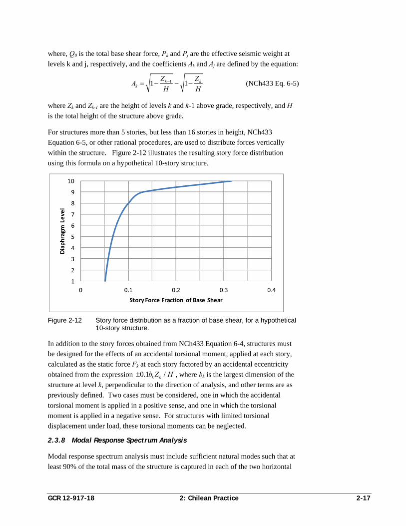
For structures more than 5 stories, but less than 16 stories in height, NCh433
Equation 6-5, or other rational procedures, are used to distribute forces vertically
within the structure. Figure 2-12 illustrates the resulting story force distribution
using this formula on a hypothetical 10-story structure.
Figure 2-12 Story force distribution as a fraction of base shear, for a hypothetical 10-story structure.
In addition to the story forces obtained from NCh433 Equation 6-4, structures must
be designed for the effects of an accidental torsional moment, applied at each story,
calculated as the static force Fk at each story factored by an accidental eccentricity
obtained from the expression /0.1 k kZ Hb , where bk is the largest dimension of the
structure at level k, perpendicular to the direction of analysis, and other terms are as
previously defined. Two cases must be considered, one in which the accidental
torsional moment is applied in a positive sense, and one in which the torsional
moment is applied in a negative sense. For structures with limited torsional
displacement under load, these torsional moments can be neglected.
2.3.8 Modal Response Spectrum Analysis
Modal response spectrum analysis must include sufficient natural modes such that at
least 90% of the total mass of the structure is captured in each of the two horizontal
1
2
3
4
5
6
7
8
9
10
0 0.1 0.2 0.3 0.4
Diaphragm
Level
Story Force Fraction of Base Shear
2-18 2: Chilean Practice GCR 12-917-18
directions, and at least 90% of the torsional inertia of the structure is captured. The
effects of accidental torsion must be considered either by displacing the center of
mass at each level an amount equal to 5% of the diaphragm dimension in the
direction perpendicular to the analysis, or by applying an accidental torsional
moment at each level, obtained as the product of the incremental story shear obtained
from the analysis and the accidental torsional eccentricity specified for static
analysis. As in the case of static analysis, two cases of accidental torsion must be
considered in response spectrum analysis, one with positive eccentricity, and one
with negative eccentricity.
The design acceleration response spectrum is defined by the equation:
0*a
IAS T
R
(NCh433 Eq. 6-8)
where I is the occupancy importance factor as defined for static analysis; A0 is the
maximum effective soil acceleration determined by seismic zone; is a modal
response coefficient; and R* is a system-, period-, and site-dependent response
modification coefficient for response spectrum analysis.
The modal response coefficient is obtained for each mode from the equation:
3
0
1 4.5
1
p
n
o
n
T
T
T
T
(NCh433 Eq. 6-9)
where Tn is the period associated with mode n; and T0 and p are parameters
associated with soil type. Figure 2-13 plots response spectra derived using NCh433
Equation 6-8, for each of the four soil types, in Zone 3, with values of the occupancy
importance factor, I, and response modification coefficient, R*, taken as unity.
The period-dependent response modification coefficient is obtained from the
equation:
*
**
00
1
0.1
TR
TT
R
(NCh433 Eq. 6-10)
where T* is the period of the mode with the highest translational mass participation in
the direction under consideration; R0 is a system-dependent response modification
coefficient varying from 11 for the most ductile systems, such as reinforced concrete
wall and moment-resisting frame buildings, to 3 for the least ductile systems, such as
partially grouted reinforced masonry wall buildings. The equation for R* is evaluated
using the fundamental period of the building along each of two orthogonal axes.
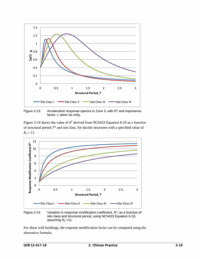
GCR 12-917-18 2: Chilean Practice 2-19
Figure 2-13 Acceleration response spectra in Zone 3, with R* and importance factor, I, taken as unity.
Figure 2-14 shows the value of R* derived from NCh433 Equation 6-10 as a function
of structural period T* and site class, for ductile structures with a specified value of
R0 = 11.
Figure 2-14 Variation in response modification coefficient, R*, as a function of site class and structural period, using NCh433 Equation 6-10, assuming R0 =11.
For shear wall buildings, the response modification factor can be computed using the
alternative formula:
0
0.2
0.4
0.6
0.8
1
1.2
1.4
0 0.5 1 1.5 2 2.5 3
Sa(T) ‐g
Structural Period, T
Site Class I Site Class II Site Class III Site Class IV
0
2
4
6
8
10
12
0 0.5 1 1.5 2 2.5 3
Response M
odification Coefficient R*
Structural Period, T
Site Class I Site Class II Site Class III Site Class IV
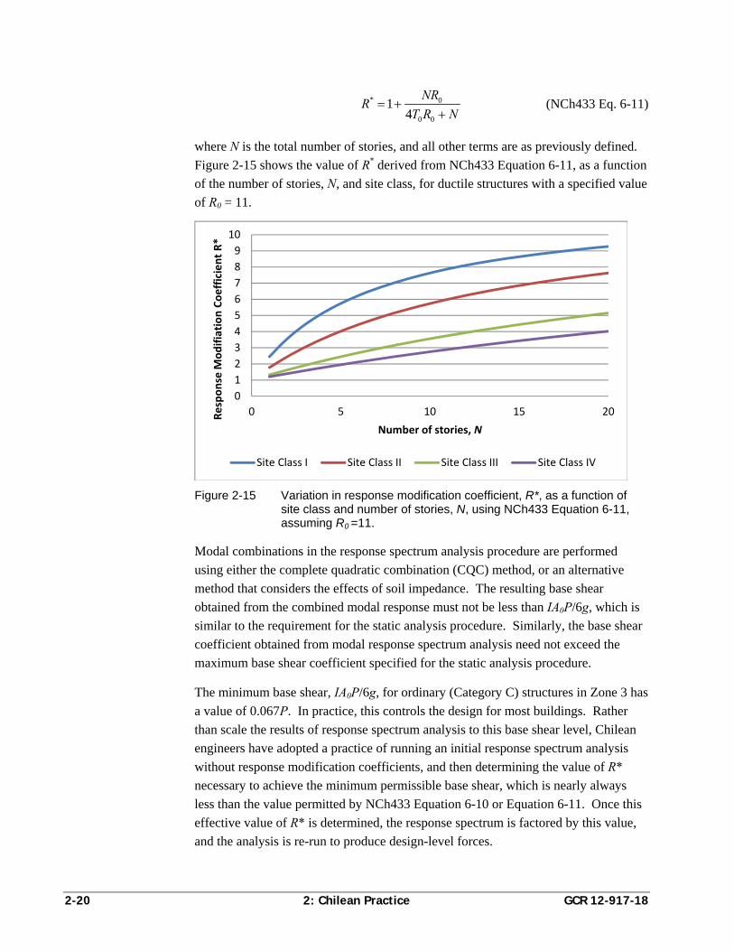
2-20 2: Chilean Practice GCR 12-917-18
* 0
0 0
14
NRR
T R N
(NCh433 Eq. 6-11)
where N is the total number of stories, and all other terms are as previously defined.
Figure 2-15 shows the value of R* derived from NCh433 Equation 6-11, as a function
of the number of stories, N, and site class, for ductile structures with a specified value
of R0 = 11.
Figure 2-15 Variation in response modification coefficient, R*, as a function of site class and number of stories, N, using NCh433 Equation 6-11, assuming R0 =11.
Modal combinations in the response spectrum analysis procedure are performed
using either the complete quadratic combination (CQC) method, or an alternative
method that considers the effects of soil impedance. The resulting base shear
obtained from the combined modal response must not be less than IA0P/6g, which is
similar to the requirement for the static analysis procedure. Similarly, the base shear
coefficient obtained from modal response spectrum analysis need not exceed the
maximum base shear coefficient specified for the static analysis procedure.
The minimum base shear, IA0P/6g, for ordinary (Category C) structures in Zone 3 has
a value of 0.067P. In practice, this controls the design for most buildings. Rather
than scale the results of response spectrum analysis to this base shear level, Chilean
engineers have adopted a practice of running an initial response spectrum analysis
without response modification coefficients, and then determining the value of R*
necessary to achieve the minimum permissible base shear, which is nearly always
less than the value permitted by NCh433 Equation 6-10 or Equation 6-11. Once this
effective value of R* is determined, the response spectrum is factored by this value,
and the analysis is re-run to produce design-level forces.
0
1
2
3
4
5
6
7
8
9
10
0 5 10 15 20Response M
odifiation Coefficient R*
Number of stories, N
Site Class I Site Class II Site Class III Site Class IV
GCR 12-917-18 3: U.S. Practice 3-1
Chapter 3
U.S. Practice
3.1 Evolution of U.S. Seismic Design Codes
In the United States, building codes are locally developed and adopted at either the
City, County, or State level. Almost all such agencies base their locally adopted
codes on one of several model building codes, generally developed by non-profit
professional associations of building officials, fire marshals and allied professionals.
For many years, most building regulation in the United States was based on one of
three different model codes: the National Building Code (NBC), developed by the
Building Officials and Code Administrators International (BOCA), the Standard
Building Code (SBC), developed by the Southern Building Code Congress
International (SBCCI), and the Uniform Building Code (UBC), developed by the
International Conference of Building Officials (ICBO). In general, local
governments in the Northeast and Central United States tended to use the NBC; the
Southeast tended to use the SBC; and the Western United States tended to use the
UBC. Each of these model codes was traditionally published on a three-year cycle.
Although these codes were generally quite similar, a regional focus caused each to be
the technical leader in areas of practice that were important in each region. The
NBC, which served the major urban centers of the Eastern United States, was known
for progressive criteria on fire and life safety issues; the SBC, which served the
hurricane-prone Southeastern United States, was known for leadership in wind
engineering; and the UBC, which served the seismically active Western United
States, was known for leadership in seismic design criteria. Provisions developed by
one model code agency in an area of leadership were often adopted by the other
model codes in later editions.
The UBC was a self-contained code that included loading criteria as well as material
design and detailing requirements for concrete, masonry, timber, and steel
construction. Material design requirements were generally based on design standards
published by industry associations, including the American Concrete Institute,
American Institute of Steel Construction, National Forest Products Association and
The Masonry Society, but were often substantially modified in the course of their
adoption. Seismic design requirements contained in the UBC were primarily
developed by the Seismology Committee of the Structural Engineers Association of
California (SEAOC), a volunteer professional group that drafted both recommended
code provisions and commentary that were submitted to the International Conference
of Building Officials for adoption.
3-2 3: U.S. Practice GCR 12-917-18
In 1971, the San Fernando earthquake near Los Angeles, California, resulted in
severe damage to modern, code-conforming buildings. In response to this
unanticipated damage, extensive study was undertaken to develop improved seismic
design criteria. This effort resulted in the publication of ATC 3-06, Tentative
Provisions for the Development of Seismic Regulations for Buildings (ATC, 1978),
which became the basis for modern seismic design provisions in the United States.
In the mid-1980s, the SEAOC Seismology Committee revised the seismic provisions
of the UBC based on the ATC 3-06 report, and the changes were implemented in the
in the 1988 edition of the UBC. Although the ATC 3-06 recommendations were
largely incorporated, the 1988 UBC included two major deviations:
Rather than basing seismic design forces on ground motion contour maps that
portrayed the risk of strong ground shaking in terms of an effective peak ground
acceleration, Ca, and an effective velocity-related acceleration Cv, from which a
design response spectrum could be constructed, the 1988 UBC continued to base
seismic design forces on a series of four seismic zones. Each seismic zone was
associated with a single value of maximum anticipated effective peak ground
acceleration, which was presumed to be broadly applicable within the zone.
Rules were provided to convert this effective peak ground acceleration into
design spectra based on site soil conditions.
Rather than utilizing a strength formulation, in which the required design seismic
forces were associated with the onset of first major yielding in response to design
ground motions, the 1988 UBC continued the use of an allowable stress design
(ASD) formulation. Specified ASD forces were set at 0.7 times the strength level
forces contained in ATC 3-06 (i.e., strength level forces divided by 1.4).
At about the same time, with funding provided by the Federal Emergency
Management Agency (FEMA) under the National Earthquake Hazards Reduction
Program, the National Institute of Building Sciences formed the Building Seismic
Safety Council (BSSC). BSSC was charged with developing a series of
recommended seismic design provisions based on the ATC 3-06 report. First
published in 1985, the NEHRP Recommended Provisions for the Development of
Seismic Regulations for New Buildings (BSSC, 1985) were more consistent with the
recommendations contained in the original ATC 3-06 report. Since that time, the
NEHRP Provisions have been further developed and continuously updated on a
3-year cycle by the BSSC Provisions Update Committee, a volunteer group of
professional engineers, researchers, and industry representatives.
In 1992, the NEHRP Provisions were first adopted into building codes when the 1991
edition was transcribed into both the NBC and SBC. Then, in 1998, the American
Society of Civil Engineers (ASCE) adopted the 1994 edition of the NEHRP
GCR 12-917-18 3: U.S. Practice 3-3
Provisions into its ASCE 7-98 Standard for Minimum Design Loads for Buildings
and Other Structures (ASCE, 2000).
In the late 1990s, the three model code organizations (BOCA, SBCCI, and ICBO)
merged into a single entity, entitled the International Code Council (ICC). The
purpose of the ICC was to publish a single, nationally applicable model building
code. The first edition of the International Building Code (ICC, 2000) adopted
seismic design criteria based on the 1997 edition of the NEHRP Recommended
Provisions for Seismic Regulations for New Buildings and Other Structures (BSSC,
1998). Subsequent editions of the IBC have been published on a 3-year cycle
including the 2003, 2006, 2009, and most recently, the 2012 editions. Beginning in
2006, the IBC adopted seismic design requirements by reference to ASCE/SEI 7-05,
Minimum Design Loads for Buildings and Other Structures (ASCE, 2006).
3.2 Operative Codes
By 2010, most local governments in the United States had adopted an edition of the
IBC, with the 2006 edition being the most commonly adopted and enforced edition.
There are, however, some U.S. communities that still use and enforce codes based on
editions of the NBC, SBC or UBC legacy codes.
In this report, the requirements of the 2006 International Building Code (ICC, 2006)
are taken as the predominant building code provisions governing design practice in
the United States. Unlike predecessor model codes, the IBC is not a self-contained
code. Instead, the IBC adopts structural design criteria through reference to a series
of national consensus standards. The two standards most relevant to the design and
construction of reinforced concrete structures are:
ASCE/SEI 7 – Minimum Design Loads for Buildings and Other Structures
ACI 318 – Building Code Requirements for Structural Concrete
3.2.1 ASCE 7 Loading Standard
The ASCE/SEI 7 Standard for Minimum Design Loads for Buildings and Other
Structures specifies loads, load combinations, and seismic design requirements for
structural systems and nonstructural components. Currently published on a 5-year
cycle, the most recent editions are ASCE/SEI 7-05 (ASCE, 2006), and ASCE/SEI
7-10 (ASCE, 2010). With the exception of subtle, but important differences in the
computation of design ground motion values, the two versions of the standard are
very similar. The 2006 IBC and 2009 IBC refer to ASCE/SEI 7-05, while the 2012
IBC refers to ASCE/SEI 7-10. This report focuses on ASCE/SEI 7-10 requirements
as the most current practice for specification of seismic design loading in the United
States.
3-4 3: U.S. Practice GCR 12-917-18
3.2.2 ACI 318 Concrete Design Standard
ACI 318 Building Code Requirements for Structural Concrete specifies requirements
for design, detailing, and construction of reinforced concrete structures. Currently
published on a 3-year cycle, recent editions include ACI 318-05 (ACI, 2005), ACI
318-08 (ACI, 2008), and most recently, ACI 318-11 (ACI, 2011). The 2006 IBC
refers to ACI 318-05 and the 2009 IBC refers to ACI 318-08. Differences between
the three latest editions of ACI 318 are subtle with regard to seismic design.
Since much of Chilean practice is based on ACI 318-05, basic reinforced concrete
design and detailing criteria are not described herein. This report focuses on
ACI 318-05 provisions governing design of reinforced concrete shear walls, and
discussion is limited to requirements, such as confinement of boundary zones in
concrete walls, which are specifically exempted in Chilean practice.
3.3 Typical U.S. Design Practice
The United States encompasses a broad range of seismic environments, from regions
with essentially no seismic risk to regions of very high risk. Seismic design criteria
specified in U.S. codes and standards vary widely depending on the seismicity of the
region. In this report, discussion is focused on U.S. practice and code requirements
associated with regions of high seismic risk.
In contrast with Chile, the cost of labor in the United States tends to be a more
significant percentage of total construction cost, driving U.S. designers towards
building configurations that minimize labor, even if this results in less than optimal
use of materials. As a result, construction practice in the United States tends towards
the use of longer spans, two-way flat slabs, and fewer structural walls. It is not
unusual for large residential structures to have two to four main shear-resisting walls
in each of two approximately orthogonal directions (Figure 3-1 and Figure 3-2).
Often, these walls are placed around centrally located elevator or service cores, and
columns are provided for gravity support where walls do not exist. Slabs are often
post-tensioned to reduce floor thickness, thereby reducing the building mass and the
associated seismic forces.
ASCE/SEI 7 limits the use of shear wall systems to buildings not exceeding 160 feet
in height. If walls are arranged to provide superior torsional resistance, this limit is
extended to 240 feet. Buildings exceeding these height limits must include a special
moment frame that is capable of resisting at least 25% of the specified seismic design
forces in combination with walls or braced frames. Recently, some engineers have
exceeded these height limits using pure shear wall systems that have been designed
using alternative means provisions of the building code. Alternative means
provisions permit the use of alternative rational criteria to justify the design of
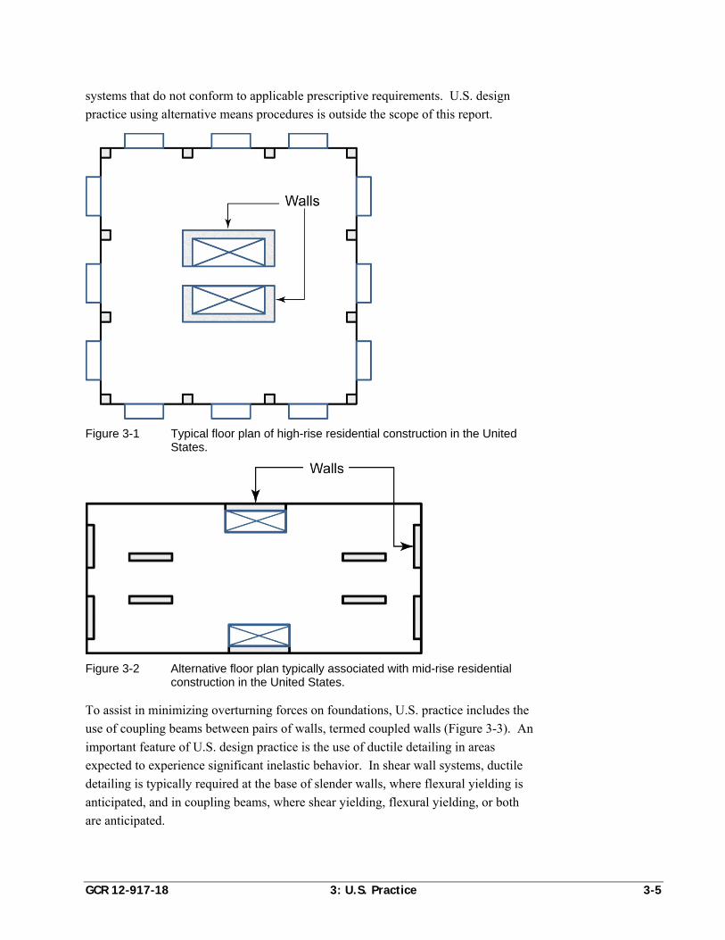
GCR 12-917-18 3: U.S. Practice 3-5
systems that do not conform to applicable prescriptive requirements. U.S. design
practice using alternative means procedures is outside the scope of this report.
Figure 3-1 Typical floor plan of high-rise residential construction in the United States.
Figure 3-2 Alternative floor plan typically associated with mid-rise residential
construction in the United States.
To assist in minimizing overturning forces on foundations, U.S. practice includes the
use of coupling beams between pairs of walls, termed coupled walls (Figure 3-3). An
important feature of U.S. design practice is the use of ductile detailing in areas
expected to experience significant inelastic behavior. In shear wall systems, ductile
detailing is typically required at the base of slender walls, where flexural yielding is
anticipated, and in coupling beams, where shear yielding, flexural yielding, or both
are anticipated.
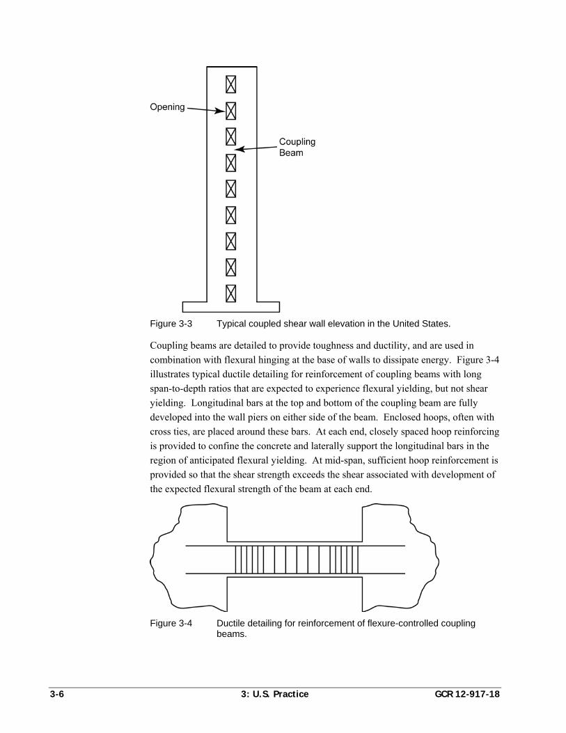
3-6 3: U.S. Practice GCR 12-917-18
Figure 3-3 Typical coupled shear wall elevation in the United States.
Coupling beams are detailed to provide toughness and ductility, and are used in
combination with flexural hinging at the base of walls to dissipate energy. Figure 3-4
illustrates typical ductile detailing for reinforcement of coupling beams with long
span-to-depth ratios that are expected to experience flexural yielding, but not shear
yielding. Longitudinal bars at the top and bottom of the coupling beam are fully
developed into the wall piers on either side of the beam. Enclosed hoops, often with
cross ties, are placed around these bars. At each end, closely spaced hoop reinforcing
is provided to confine the concrete and laterally support the longitudinal bars in the
region of anticipated flexural yielding. At mid-span, sufficient hoop reinforcement is
provided so that the shear strength exceeds the shear associated with development of
the expected flexural strength of the beam at each end.
Figure 3-4 Ductile detailing for reinforcement of flexure-controlled coupling beams.
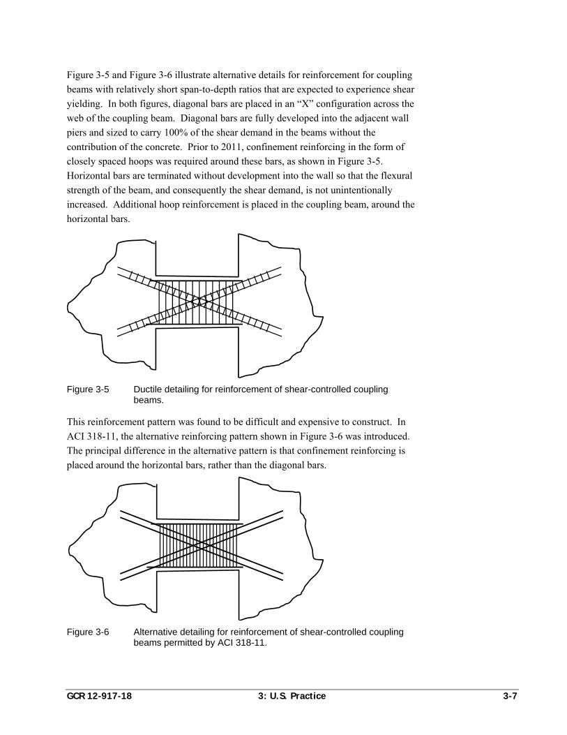
GCR 12-917-18 3: U.S. Practice 3-7
Figure 3-5 and Figure 3-6 illustrate alternative details for reinforcement for coupling
beams with relatively short span-to-depth ratios that are expected to experience shear
yielding. In both figures, diagonal bars are placed in an “X” configuration across the
web of the coupling beam. Diagonal bars are fully developed into the adjacent wall
piers and sized to carry 100% of the shear demand in the beams without the
contribution of the concrete. Prior to 2011, confinement reinforcing in the form of
closely spaced hoops was required around these bars, as shown in Figure 3-5.
Horizontal bars are terminated without development into the wall so that the flexural
strength of the beam, and consequently the shear demand, is not unintentionally
increased. Additional hoop reinforcement is placed in the coupling beam, around the
horizontal bars.
Figure 3-5 Ductile detailing for reinforcement of shear-controlled coupling beams.
This reinforcement pattern was found to be difficult and expensive to construct. In
ACI 318-11, the alternative reinforcing pattern shown in Figure 3-6 was introduced.
The principal difference in the alternative pattern is that confinement reinforcing is
placed around the horizontal bars, rather than the diagonal bars.
Figure 3-6 Alternative detailing for reinforcement of shear-controlled coupling
beams permitted by ACI 318-11.
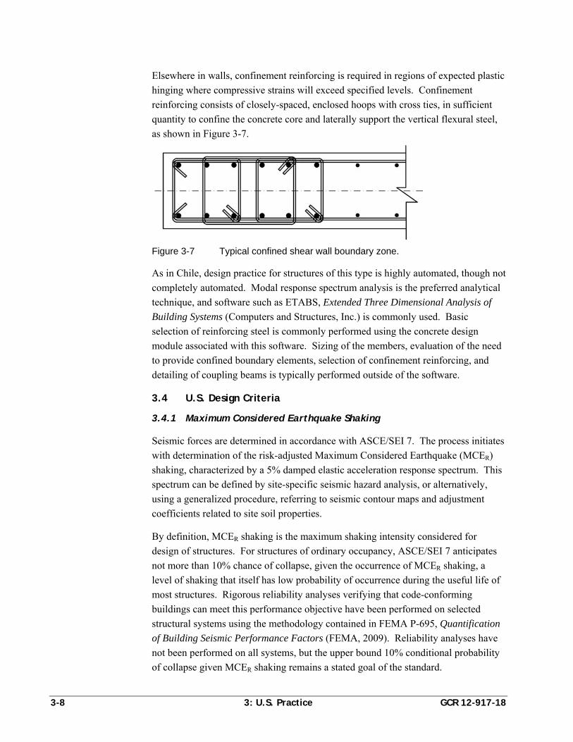
3-8 3: U.S. Practice GCR 12-917-18
Elsewhere in walls, confinement reinforcing is required in regions of expected plastic
hinging where compressive strains will exceed specified levels. Confinement
reinforcing consists of closely-spaced, enclosed hoops with cross ties, in sufficient
quantity to confine the concrete core and laterally support the vertical flexural steel,
as shown in Figure 3-7.
Figure 3-7 Typical confined shear wall boundary zone.
As in Chile, design practice for structures of this type is highly automated, though not
completely automated. Modal response spectrum analysis is the preferred analytical
technique, and software such as ETABS, Extended Three Dimensional Analysis of
Building Systems (Computers and Structures, Inc.) is commonly used. Basic
selection of reinforcing steel is commonly performed using the concrete design
module associated with this software. Sizing of the members, evaluation of the need
to provide confined boundary elements, selection of confinement reinforcing, and
detailing of coupling beams is typically performed outside of the software.
3.4 U.S. Design Criteria
3.4.1 Maximum Considered Earthquake Shaking
Seismic forces are determined in accordance with ASCE/SEI 7. The process initiates
with determination of the risk-adjusted Maximum Considered Earthquake (MCER)
shaking, characterized by a 5% damped elastic acceleration response spectrum. This
spectrum can be defined by site-specific seismic hazard analysis, or alternatively,
using a generalized procedure, referring to seismic contour maps and adjustment
coefficients related to site soil properties.
By definition, MCER shaking is the maximum shaking intensity considered for
design of structures. For structures of ordinary occupancy, ASCE/SEI 7 anticipates
not more than 10% chance of collapse, given the occurrence of MCER shaking, a
level of shaking that itself has low probability of occurrence during the useful life of
most structures. Rigorous reliability analyses verifying that code-conforming
buildings can meet this performance objective have been performed on selected
structural systems using the methodology contained in FEMA P-695, Quantification
of Building Seismic Performance Factors (FEMA, 2009). Reliability analyses have
not been performed on all systems, but the upper bound 10% conditional probability
of collapse given MCER shaking remains a stated goal of the standard.
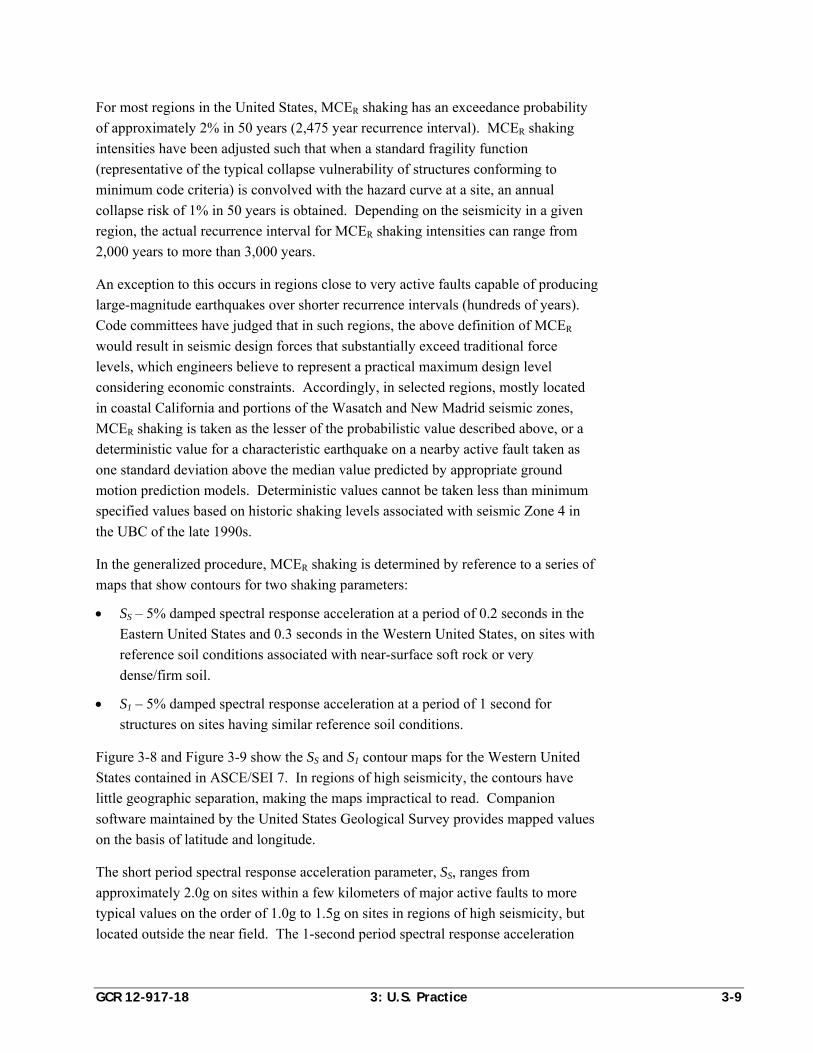
GCR 12-917-18 3: U.S. Practice 3-9
For most regions in the United States, MCER shaking has an exceedance probability
of approximately 2% in 50 years (2,475 year recurrence interval). MCER shaking
intensities have been adjusted such that when a standard fragility function
(representative of the typical collapse vulnerability of structures conforming to
minimum code criteria) is convolved with the hazard curve at a site, an annual
collapse risk of 1% in 50 years is obtained. Depending on the seismicity in a given
region, the actual recurrence interval for MCER shaking intensities can range from
2,000 years to more than 3,000 years.
An exception to this occurs in regions close to very active faults capable of producing
large-magnitude earthquakes over shorter recurrence intervals (hundreds of years).
Code committees have judged that in such regions, the above definition of MCER
would result in seismic design forces that substantially exceed traditional force
levels, which engineers believe to represent a practical maximum design level
considering economic constraints. Accordingly, in selected regions, mostly located
in coastal California and portions of the Wasatch and New Madrid seismic zones,
MCER shaking is taken as the lesser of the probabilistic value described above, or a
deterministic value for a characteristic earthquake on a nearby active fault taken as
one standard deviation above the median value predicted by appropriate ground
motion prediction models. Deterministic values cannot be taken less than minimum
specified values based on historic shaking levels associated with seismic Zone 4 in
the UBC of the late 1990s.
In the generalized procedure, MCER shaking is determined by reference to a series of
maps that show contours for two shaking parameters:
SS – 5% damped spectral response acceleration at a period of 0.2 seconds in the
Eastern United States and 0.3 seconds in the Western United States, on sites with
reference soil conditions associated with near-surface soft rock or very
dense/firm soil.
S1 – 5% damped spectral response acceleration at a period of 1 second for
structures on sites having similar reference soil conditions.
Figure 3-8 and Figure 3-9 show the SS and S1 contour maps for the Western United
States contained in ASCE/SEI 7. In regions of high seismicity, the contours have
little geographic separation, making the maps impractical to read. Companion
software maintained by the United States Geological Survey provides mapped values
on the basis of latitude and longitude.
The short period spectral response acceleration parameter, SS, ranges from
approximately 2.0g on sites within a few kilometers of major active faults to more
typical values on the order of 1.0g to 1.5g on sites in regions of high seismicity, but
located outside the near field. The 1-second period spectral response acceleration
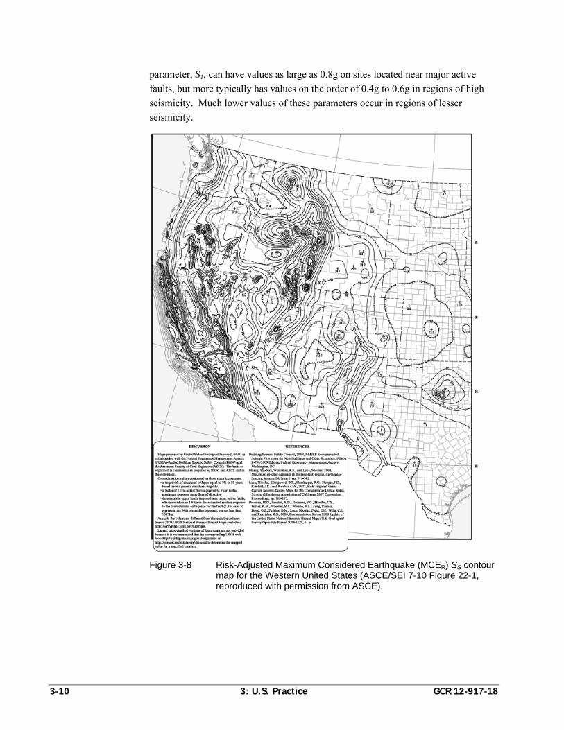
3-10 3: U.S. Practice GCR 12-917-18
parameter, S1, can have values as large as 0.8g on sites located near major active
faults, but more typically has values on the order of 0.4g to 0.6g in regions of high
seismicity. Much lower values of these parameters occur in regions of lesser
seismicity.
Figure 3-8 Risk-Adjusted Maximum Considered Earthquake (MCER) SS contour map for the Western United States (ASCE/SEI 7-10 Figure 22-1, reproduced with permission from ASCE).
GCR 12-917-18 3: U.S. Practice 3-11
Figure 3-9 Risk-Adjusted Maximum Considered Earthquake (MCER) S1 contour
map for the Western United States (ASCE/SEI 7-10, Figure 22-2, reproduced with permission from ASCE).
3.4.2 Site Class
Most structures are not located on sites matching the reference site conditions
associated with the mapped values of SS and S1. ASCE/SEI 7 accounts for site effects
on spectral shape through assignment of site coefficients based on soil type (site
class). Six site classes are defined:
Site Class A. Sites with near-surface hard rock, having an average shear wave
velocity of 5,000 ft/s, or greater, in the upper 100 feet.
3-12 3: U.S. Practice GCR 12-917-18
Site Class B. Sites with near-surface rock having average shear wave velocity
ranging from 2,500 ft/s to 5,000 ft/s in the upper 100 feet.
Site Class C. Sites with very dense soil or soft rock in the upper 100 feet and
average shear wave velocities ranging from 1,200 ft/s to 2,500 ft/s; standard
penetration resistance exceeding 50 blows/ft; or undrained shear strengths
exceeding 2,000 psf.
Site Class D. Sites with stiff soils in the upper 100 feet and average shear wave
velocities ranging from 600 ft/s to 1,200 ft/s; standard penetration resistance
ranging from 15 blows/ft to 25 blows/ft; or undrained shear strengths ranging
from 1,000 psf to 2000 psf.
Site Class E. Sites with soft soils in the upper 100 feet and average shear wave
velocities less than 600 ft/s; standard penetration resistance less than 15 blows/ft;
or undrained shear strengths less than 1,000 psf.
Site Class F. Sites with near surface soils that are vulnerable to failure or
collapse under seismic loading including liquefiable soils, quick and highly
sensitive clay, and collapsible, weakly cemented soils.
Site classes are determined by site-specific study. The use of default Site Class D is
permitted unless the authority having jurisdiction has reason to believe that Site
Classes E or F are present. For all sites except Site Class F, ASCE/SEI 7 specifies
spectral shape modification factors, Fa and Fv that are used to adjust the mapped
MCER spectral response acceleration parameters to site-adjusted values, SMS and SM1,
using the following equations:
MS a SS F S (ASCE 7 Eq. 11.4-1)
1 1M vS F S (ASCE 7 Eq. 11.4-2)
Values of Fa and Fv depend on the site classification and the magnitude of SS and S1,
accounting for nonlinearity in soil response at high-amplitude shaking. In regions of
high seismicity, values of Fa range from 0.8 on Site Class A sites to 1.1 on softer soil
sites. Values of Fv range from 0.8 on Site Class A sites to 2.4 on Site Class E sites.
On Site Class F sites, site-specific response analysis is required to set the values of
these coefficients.
3.4.3 Design Earthquake Shaking
Seismic design forces are determined based on spectral response acceleration
parameters for a reduced level of shaking, defined as Design Earthquake Shaking.
Design earthquake spectral response acceleration parameters are obtained from the
following equations:
2
3DS MSS S (ASCE 7 Eq. 11.4-3)
GCR 12-917-18 3: U.S. Practice 3-13
1 1
2
3D MS S (ASCE 7 Eq. 11.4-4)
3.4.4 Risk Category
Buildings are classified based on the risk to human life, health, and welfare as a result
of damage or failure based on their occupancy or use. Four categories of risk are
defined:
Risk Category I. Buildings and other structures that are not normally used for
human habitation, such as barns and certain storage structures, which pose
minimal risk to life in the event of failure.
Risk Category II. Ordinary occupancy buildings, including most commercial,
industrial, and residential uses.
Risk Category III. Buildings and other structures that pose a substantial risk to
life in the event of failure, including assembly occupancies with large numbers of
persons; certain education facilities; prisons; water treatment and power plants;
and structures housing limited quantities of potentially hazardous materials.
Risk Category IV. Buildings and other structures that pose a substantial risk to
the surrounding community in the event of failure, including buildings
designated as essential facilities necessary to assist in post-disaster recovery
operations such as hospitals, police stations, and fire stations.
Importance factors, Ie, ranging from 1.0 to 1.5 are applied to seismic design forces
based on the assigned Risk Category.
3.4.5 Seismic Design Category
Buildings are assigned to a Seismic Design Category (SDC) considering the assigned
Risk Category and the design earthquake spectral response acceleration parameters,
SDS and SD1. Six Seismic Design Categories are defined, ranging from A to F.
Structures in Seismic Design Category A are not expected to experience damaging
earthquake shaking. They are not required to be designed for seismic resistance, but
they must meet basic structural integrity criteria including a complete lateral force-
resisting system capable of resisting at least 1% of the weight of the building applied
as a lateral force in each direction.
Seismic Design Category B includes Risk Category I, II, and III structures in regions
of low seismicity, expected to experience Modified Mercalli Intensity (MMI) VI or
lesser shaking. They must be designed for seismic forces determined using spectral
response coefficients, but there are few rules prescribing detailing requirements and
no limitations on the use of various structural systems. Similarly, there are no
requirements for seismic bracing and anchorage of nonstructural components.
3-14 3: U.S. Practice GCR 12-917-18
Seismic Design Category C includes Risk Category IV structures in regions of
moderate seismicity, and Risk Category I, II and III structures in regions of moderate
seismicity expected to experience MMI VII or lesser shaking. In Seismic Design
Category C, there are some limitations on the use of structural systems of different
heights, and nonstructural components must be anchored and braced to resist seismic
forces.
Seismic Design Category D includes Risk Category IV structures in regions of
moderate seismicity, and Risk Category I, II and III structures in regions of high
seismicity expected to experience MMI VIII to IX shaking intensity. There are
restrictions on the use of certain structural systems along with extensive prescriptive
requirements for seismic detailing. Nonstructural components must be anchored and
braced.
Seismic Design Category E applies to Risk Category I, II and III structures located
within a few kilometers of major active faults, and Seismic Design Category F
applies to Risk Category IV structures that are similarly located near such faults. In
these Seismic Design Categories there are additional limitations on the use of
structural systems and limitations on permissible structural irregularities. Most
structures in regions of high seismicity are assigned to Seismic Design Category D,
or higher.
3.4.6 Load Combinations
Design earthquake loads, E, include loads intended to account for the effects of both
horizontal, Eh, and vertical, Ev, shaking. Horizontal earthquake loads are determined
by any of several acceptable methods of analysis including equivalent lateral force,
modal response spectrum analysis, linear response history, or nonlinear response
history analysis. Vertical earthquake loads are taken as a fraction of the dead load
effect on each member, D, using the equation:
0.2v DSE S D (ASCE 7 Eq. 12.4.4)
Vertical earthquake effects can be taken as positive (in the same sense as dead load
effects) or negative (in the opposite sense as dead load effects). Horizontal
earthquake effects are obtained using the equation:
h EE Q (ASCE 7 Eq. 12.4.3)
where QE are the load effects obtained as a result of lateral analysis, and is a
reliability factor associated with the redundancy and regularity of the structure. For
structures with sufficiently redundant seismic force-resisting systems and regular
configurations, this factor is assigned a value of unity. A structure is considered to be
redundant if the removal of any one seismic force-resisting element within a story
neither creates an extreme torsional irregularity, nor results in a reduction of story
GCR 12-917-18 3: U.S. Practice 3-15
shear exceeding 33% of the strength prior to removal of the element. Structures not
complying with these criteria are assigned a redundancy factor of 1.3.
Vertical and horizontal seismic load effects are calculated on a strength basis. When
combined with other load effects using strength design procedures, they are assigned
a load factor of 1.0. When used in Allowable Stress Design procedures, these load
effects are reduced by a factor of 0.7 (i.e., divided by 1.4). Load combinations that
must be considered using strength design procedures include:
1.2 0.2 0.2DS ES D Q L S (ASCE 7 Eq. 12.4.2.3-5)
0.9 0.2 1.6DS ES D Q H (ASCE 7 Eq. 12.4.2.3-7)
where L is the effect of live loads, S is the effect of snow, and H is the effect of
lateral earth pressure, ground water or bulk materials.
The earthquake effects in the above load combinations are substantially reduced from
force levels associated with elastic response to design earthquake shaking,
considering the beneficial effects of inelastic behavior as a load-limiting mechanism.
Certain critical elements that are deemed sensitive to the effects of overloading, the
failure of which could lead to unacceptable behavior, are required to have additional
strength to resist the maximum forces they are likely to experience as a result of
structural overstrength. Such elements include columns beneath discontinuous
frames and walls; connections in steel frames; primary seismic force-resisting
elements in certain weak/soft story structures; and diaphragm chords and collectors.
These elements must be designed for the following special load combinations:
1.2 0.2 Ω 0.2DS o ES D Q L S (ASCE 7 Eq. 12.4.3.2-5)
0.9 0.2 Ω 1.6DS o ES D Q H (ASCE 7 Eq. 12.4.3.2-7)
where o is a structural system-dependent factor, with values generally ranging from
2 to 3, that is intended to account for the effects of structural overstrength. The
product of oQE need not exceed the maximum force that the structural system is
capable of delivering to the element, as determined by appropriate nonlinear analysis.
All other terms are as previously defined.
Although not used in the design of concrete structures, ASCE/SEI 7 also includes
Allowable Stress Design (ASD) load combinations that can be used in the design of
structural steel, cold-formed steel, timber, and masonry structures. ASCE/SEI 7 does
not permit a 1/3 increase in allowable stresses for ASD load combinations that
include transient loads. However, the IBC has an alternative set of ASD load
combinations that do include the use of a 1/3 allowable stress increase. Because IBC
load combinations are more familiar to designers, and they result in somewhat more
3-16 3: U.S. Practice GCR 12-917-18
economical designs, the ASD combinations specified in ASCE/SEI 7 are rarely used
in practice.
In higher Seismic Design Categories, earthquake response in two orthogonal
directions must be evaluated by simultaneously considering 100% of the computed
seismic forces due to response in one direction, with 30% of the seismic forces
computed for response in the orthogonal direction.
3.4.7 Structural Systems
ASCE/SEI 7 recognizes more than 80 different structural systems. Each system is
designated by its basic classification (e.g., bearing wall, building frame, moment-
resisting frame, or dual system); material of construction (e.g., masonry, reinforced
concrete, structural steel, cold-formed steel, timber); and extent of seismic-resistant
design and detailing requirements incorporated in the design procedures (e.g.,
special, intermediate, or ordinary). Systems thought to be capable of highly ductile
performance with extensive safeguards preventing brittle failure modes are termed
“special” systems. Systems with few safeguards against brittle failure, and are
capable of only limited levels of inelastic response, are termed “ordinary.” Structures
with fewer safeguards than “special” systems and more safeguards than “ordinary”
systems are termed “intermediate.” Systems that have no provisions for ductile
performance are termed “plain” or “not detailed for seismic resistance.” These
designations lead to structural system names including special concrete bearing walls,
intermediate concrete moment frames, and ordinary steel concentrically braced
frames.
In Seismic Design Categories D, E, and F, there are extensive restrictions on the use
of many of these structural systems, depending on height and Seismic Design
Category. Generally, systems designated as “special” are permitted in these design
categories, while systems designated as “intermediate” or “ordinary” may be
permitted only for structures of limited height, or not permitted at all. All structures
exceeding 160 feet in height are required to have a special moment frame capable of
resisting at least 25% of the required minimum design seismic forces, unless they
conform to certain configuration and regularity criteria. All structures taller than 240
feet must have such frames, regardless of their configuration or regularity.
Values of key design coefficients, R, Cd, and o are assigned in ASCE/SEI 7
Table 12.2-1 based on structural system designation. The response modification
coefficient, R, is used to account for inherent system ductility and overstrength to
derive acceptable minimum design strength levels. The deflection amplification
factor, Cd, is used to amplify lateral displacements computed under design force
levels to approximate actual displacements that will be experienced under MCER
shaking. The overstrength factor, o, is used to amplify design forces of certain
critical elements to protect against the effects of structural overstrength.
GCR 12-917-18 3: U.S. Practice 3-17
3.4.8 Irregularities
Irregularity associated with geometric, strength, or stiffness conditions can result in
concentration of inelastic demands that is not well predicted by elastic analysis
methods. Irregularities are categorized as either horizontal or vertical irregularities.
Horizontal irregularities include:
Torsional irregularity. Characterized by response under static applied forces
that result in a story drift profile at any level in which the drift at one side is
greater than 1.2 times the average story drift.
Extreme torsional irregularity. Similar to torsional irregularity, except that the
drift at one side is greater than 1.4 times the average story drift.
Reentrant corner irregularity. A plan shape with two or more projecting
wings (e.g., “L-shaped”) in which both plan projections beyond the reentrant
corner exceed 15% of the dimension of the building in the direction under
consideration.
Diaphragm discontinuity irregularity. Characterized by diaphragm openings
that exceed 50% of the gross floor area at a level.
Out-of-plane offset irregularity. A condition in which a line of lateral
resistance at a floor level is shifted horizontally in a direction perpendicular to
the line of resistance at the level above.
Nonparallel system irregularity. A configuration in which major vertical
elements of the seismic force-resisting system are not aligned with the major
orthogonal axes of the building.
Vertical irregularities include:
Stiffness irregularity. A condition in which the lateral stiffness of any story is
less than 70% of the stiffness in the story immediately above, or less than 80% of
the average stiffness of the three stories above.
Extreme stiffness irregularity. A condition in which the lateral stiffness of any
story is less than 60% of the story immediately above, or less than 70% of the
average stiffness of the three stories above.
Weight irregularity. A condition in which the effective seismic mass of any
story is greater than 150% of the effective mass of an adjacent story.
Vertical geometric irregularity. A setback-type geometric condition in which
the horizontal dimension of the seismic force-resisting system in any story is
greater than 130% of the dimension in an adjacent story.
3-18 3: U.S. Practice GCR 12-917-18
In-plane discontinuity irregularity. An in-plane offset in a vertical element of
the seismic force-resisting system that results in overturning demands on a
supporting column, beam, or similar element below.
Weak story irregularity. A condition in which the lateral strength of any story
is less than 80% of the strength in the story above.
Extreme weak story irregularity. A condition in which the lateral strength of
any story is less than 65% of the strength in the story above.
The presence of one or more irregularities can trigger a requirement to design the
structure using three-dimensional analysis or dynamic analysis. Irregularities can
also force certain elements of the seismic force-resisting system to be designed with
greater strength, considering the potential effects of structural overstrength. The
presence of extreme soft or weak story irregularities is prohibited in Seismic Design
Categories D, E, and F.
3.4.9 Analysis Procedures
ASCE/SEI 7 permits a number of different analytical procedures for determining
horizontal seismic design forces, and their load effects, QE, on structural elements:
Equivalent lateral force (ELF) procedure
Simplified lateral force analysis procedure
Modal response spectrum analysis procedure
Response history procedure
The equivalent lateral force procedure is a linear static analysis procedure that is
permitted for structures with regular configuration, regular strength and mass
distribution, and heights less than 160 feet. Regular structures with heights
exceeding 160 feet can be designed using this procedure if the fundamental period of
response does not exceed 3.5TS, where TS is given by the equation:
1 /S D DST S S
The simplified lateral force procedure is a simplified version of the equivalent lateral
force procedure that can be used for 1-, 2- or 3-story structures with regular
configurations, and is not discussed further in this report.
The modal response spectrum analysis procedure is permitted for use with any
structure, as are the linear and nonlinear response history procedures. In practice,
however, response history procedures are seldom used, and only the equivalent
lateral force and modal response spectrum analysis procedures are discussed further.
GCR 12-917-18 3: U.S. Practice 3-19
3.4.10 Equivalent Lateral Force Procedure
The total design lateral force in each direction, V, is determined from the equation:
SV C W (ASCE 7 Eq. 12.8-1)
where W is the effective seismic weight taken as the dead load of the structure and all
permanent equipment and furnishings. In storage and warehouse occupancies, 25%
of the design floor live load is included in the effective seismic weight. In regions
with ground snow loads exceeding 30 psf, 20% of the uniform design snow load is
included in the seismic weight. In occupancies that include a significant number of
interior partitions, the weight of these partitions is also included in the seismic
weight, but is not taken as less than 10 psf over the floor area.
The total design lateral force, V, also called a base shear force, represents the
minimum permissible strength to resist seismic forces, prior to onset of first
significant yielding. For structures with significant inelastic response capability, the
minimum design base shear force is set at a fraction of the strength necessary to resist
design earthquake shaking without damage.
The seismic response coefficient, CS, is a base shear coefficient obtained from a
series of equations. The basic value of this coefficient is determined from:
DSS
e
SC
R
I
(ASCE 7 Eq. 12.8-2)
where SDS is the design spectral response acceleration parameter at short periods; R is
the structural system-dependent response modification coefficient, and Ie is a risk
category-dependent importance factor. The response modification coefficient, R,
ranges from a value of 8 for highly ductile systems (e.g., special moment frames of
steel or concrete) to values as low as 1.5 for systems that have little ability to absorb
inelastic response. The importance factor, Ie, is assigned a value of 1.0 for Risk
Category I and II structures, 1.25 for Risk Category III structures, and 1.5 for Risk
Category IV structures.
For structures with first mode natural periods less than the long-period transitional
period, TL, the base shear coefficient need not exceed the value obtained from:
1DS
e
SC
RT
I
(ASCE 7 Eq. 12.8-3)
where SD1 is the design spectral response acceleration parameter at a period of
1 second, and T is the period in the fundamental translational mode in the direction
under consideration. The fundamental period, T, can be determined through modal
3-20 3: U.S. Practice GCR 12-917-18
analysis, by applying the Rayleigh method, or using the approximate period equation
of the form:
xa t nT C h (ASCE 7 Eq. 12.8-7)
where hn is the height of the structure above the base plane, Ct is a coefficient ranging
from 0.2 to 0.3, and x is a coefficient ranging from 0.75 to 0.9. Both Ct and x depend
on the type of seismic force-resisting system, and have been set based on correlation
with measured periods obtained from strong motion recording instruments in typical
buildings. If period is determined by analysis, the value cannot be taken greater than
CuTa, where Cu is a coefficient that varies from 1.4 in regions of high seismicity to
1.7 in regions of lower seismicity. This limit is intended to prevent engineers from
determining period using unrealistic analytical models that result in excessively small
design base shear forces.
The long-period transitional period, TL, represents the period at which design
response spectra will generally transition from the constant-velocity domain to the
constant displacement domain. The value of TL is obtained from a map provided
with the provisions, and depends on the magnitude of earthquakes dominating the
hazard within a region. In the Western United States, the value of TL generally
ranges from a low of 8 seconds to a high of 12 seconds. For structures with periods
exceeding TL, the value of CS need not exceed the value obtained from:
1
2
D LS
e
S TC
RT
I
(ASCE 7 Eq. 12.8-4)
Regardless of the value of CS obtained from ASCE/SEI 7 equations 12.8-3 and
12.8-4, the value is never permitted to be less than:
0.044 0.01S DS eC S I (ASCE 7 Eq. 12.8-5)
On sites that are located within the near field of major active faults, as characterized
by having a mapped 1-second spectral response acceleration parameter, S1, equal to
or greater than 0.6, the value of CS also cannot be taken less than the value obtained
from:
10.5 / /S eC S R I (ASCE 7 Eq. 12.8-6)
Figure 3-10 plots the variation in base shear coefficient, CS, as a function of period,
for bearing wall structures with special reinforced concrete shear walls located on
sites conforming to Site Classes B, C, D, and E, with mapped spectral response
acceleration parameters SS equal to 1.5 and S1 equal to 0.6. Sites with these values
are located in regions of high seismicity, near one or more major active faults, but are
outside the region where MCER ground shaking is limited by characteristic
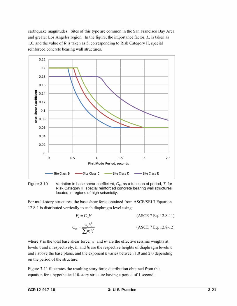
GCR 12-917-18 3: U.S. Practice 3-21
earthquake magnitudes. Sites of this type are common in the San Francisco Bay Area
and greater Los Angeles region. In the figure, the importance factor, Ie, is taken as
1.0, and the value of R is taken as 5, corresponding to Risk Category II, special
reinforced concrete bearing wall structures.
Figure 3-10 Variation in base shear coefficient, CS, as a function of period, T, for Risk Category II, special reinforced concrete bearing wall structures located in regions of high seismicity.
For multi-story structures, the base shear force obtained from ASCE/SEI 7 Equation
12.8-1 is distributed vertically to each diaphragm level using:
x vxF C V (ASCE 7 Eq. 12.8-11)
k
x xvx k
i i
w hC
w h
(ASCE 7 Eq. 12.8-12)
where V is the total base shear force, wx and wi are the effective seismic weights at
levels x and i, respectively, hx and hi are the respective heights of diaphragm levels x
and i above the base plane, and the exponent k varies between 1.0 and 2.0 depending
on the period of the structure.
Figure 3-11 illustrates the resulting story force distribution obtained from this
equation for a hypothetical 10-story structure having a period of 1 second.
0
0.02
0.04
0.06
0.08
0.1
0.12
0.14
0.16
0.18
0.2
0.22
0 0.5 1 1.5 2 2.5
Base Shear Coefficient
First Mode Period, seconds
Site Class B Site Class C Site Class D Site Class E
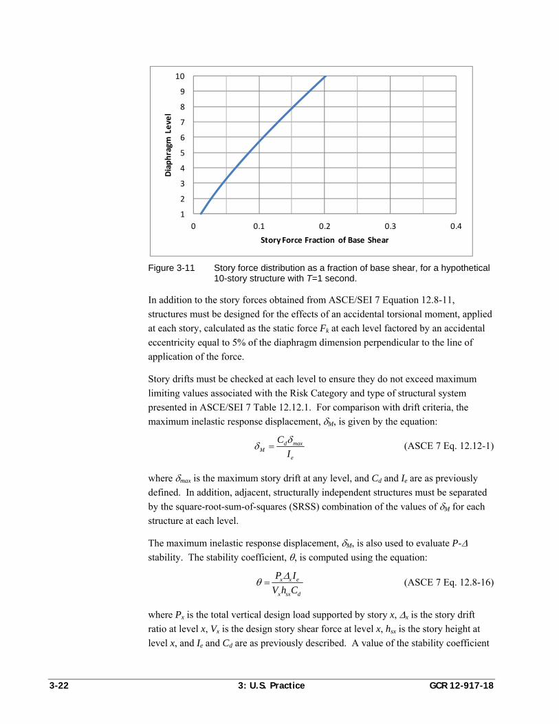
3-22 3: U.S. Practice GCR 12-917-18
Figure 3-11 Story force distribution as a fraction of base shear, for a hypothetical 10-story structure with T=1 second.
In addition to the story forces obtained from ASCE/SEI 7 Equation 12.8-11,
structures must be designed for the effects of an accidental torsional moment, applied
at each story, calculated as the static force Fk at each level factored by an accidental
eccentricity equal to 5% of the diaphragm dimension perpendicular to the line of
application of the force.
Story drifts must be checked at each level to ensure they do not exceed maximum
limiting values associated with the Risk Category and type of structural system
presented in ASCE/SEI 7 Table 12.12.1. For comparison with drift criteria, the
maximum inelastic response displacement, M, is given by the equation:
d maxM
e
C
I
(ASCE 7 Eq. 12.12-1)
where max is the maximum story drift at any level, and Cd and Ie are as previously
defined. In addition, adjacent, structurally independent structures must be separated
by the square-root-sum-of-squares (SRSS) combination of the values of M for each
structure at each level.
The maximum inelastic response displacement, M, is also used to evaluate P-
stability. The stability coefficient, , is computed using the equation:
x x e
x sx d
P I
V h C
(ASCE 7 Eq. 12.8-16)
where Px is the total vertical design load supported by story x, x is the story drift
ratio at level x, Vx is the design story shear force at level x, hsx is the story height at
level x, and Ie and Cd are as previously described. A value of the stability coefficient
1
2
3
4
5
6
7
8
9
10
0 0.1 0.2 0.3 0.4
Diaphragm
Level
Story Force Fraction of Base Shear
GCR 12-917-18 3: U.S. Practice 3-23
greater than or equal to 0.1 requires specific consideration of P- effects in the
analysis. A value of the stability coefficient that exceeds a limiting value, designated
max, is not permissible unless suitable nonlinear analysis is used to demonstrate
adequate stability.
3.4.11 Modal Response Spectrum Analysis
Modal response spectrum analysis must include sufficient natural modes such that at
least 90% of the total mass of the structure is captured in each of the two horizontal
directions, and at least 90% of the torsional inertia of the structure is captured. The
effects of accidental torsion must be considered by displacing the center of mass at
each level an amount equal to 5% of the diaphragm dimension in the direction
perpendicular to the analysis.
The design acceleration response spectrum can be determined by site-specific hazard
analysis or a generalized procedure based on the ground motion maps used for
equivalent lateral force analysis. If site-specific seismic hazard analysis is used, a 5%
damped, Maximum Considered response spectrum is determined, and the design
spectrum is taken as 2/3 of the amplitude of the Maximum Considered spectrum.
The generalized procedure uses the design spectral response acceleration parameters,
SDS and SD1, to develop the design spectrum. This spectrum follows the same basic
shape as the base shear coefficient used in the equivalent lateral force procedure, and
consists of four separate domains:
For periods less than T0 = 0.2SD1/SDS, the spectrum increases linearly from a
value of SDS/2.5.
From period T0 to period TS, the spectrum has a constant value, SDS.
From period TS to period TL, the spectrum takes on the hyperbolic shape given by
SD1/T.
For periods greater than TL, the spectrum takes on the parabolic shape given by
SD1TL/T2.
Figure 3-12 presents generalized design response spectra for a Risk Category II
structure located on sites conforming to Site Classes B, C, D, and E, with mapped
spectral response acceleration parameters SS equal to 1.5 and S1 equal to 0.6. For the
spectra shown in the figure, the response modification coefficient, R, and importance
factor, Ie, have been taken as unity.
Response quantities obtained from modal response spectrum analysis, including
individual element forces and drifts, are combined using the square-root-sum-of-
squares (SRSS) method, or in the case of closely spaced modes, by the complete
quadratic combination (CQC) method, and then scaled by the quantity Ie/R. In each
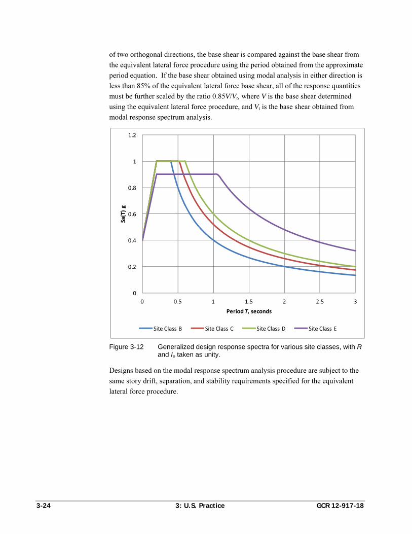
3-24 3: U.S. Practice GCR 12-917-18
of two orthogonal directions, the base shear is compared against the base shear from
the equivalent lateral force procedure using the period obtained from the approximate
period equation. If the base shear obtained using modal analysis in either direction is
less than 85% of the equivalent lateral force base shear, all of the response quantities
must be further scaled by the ratio 0.85V/Vt, where V is the base shear determined
using the equivalent lateral force procedure, and Vt is the base shear obtained from
modal response spectrum analysis.
Figure 3-12 Generalized design response spectra for various site classes, with R and Ie taken as unity.
Designs based on the modal response spectrum analysis procedure are subject to the
same story drift, separation, and stability requirements specified for the equivalent
lateral force procedure.
0
0.2
0.4
0.6
0.8
1
1.2
0 0.5 1 1.5 2 2.5 3
Sa(T) g
Period T, seconds
Site Class B Site Class C Site Class D Site Class E
GCR 12-917-18 4: Comparison of U.S. and Chilean Seismic Design Requirements 4-1
Chapter 4
Comparison of U.S. and Chilean Seismic Design Requirements
This chapter presents a comparison of U.S. and Chilean seismic design requirements,
including seismic design loading and reinforced concrete seismic design provisions,
over the period 1985–2010. This information has been excerpted from detailed
summaries of Chilean seismic design requirements in Chapter 2 and U.S. seismic
design requirements in Chapter 3.
4.1 Seismic Design Loading
The Chilean loading standard in effect at the time of the 2010 Maule earthquake was
NCh433.Of96, Earthquake Resistant Design of Buildings (INN, 1996). The most
current practice for specifying seismic design loading in the United States is
ASCE/SEI 7-10, Minimum Design Loads for Buildings and Other Structures (ASCE,
2010). Relevant provisions from these two standards are summarized in side-by-side
format in Table 4-1, together with commentary on substantive differences.
Chilean codes evolved from U.S. practice in the mid-1990s. Important developments
in U.S. codes that have not been reflected in Chilean practice over this period include:
Adoption of performance goals characterized by maximum acceptable
probability of collapse conditioned on the occurrence of Maximum Considered
Earthquake ground shaking.
Definition of ground motion by reference to spectral response acceleration
contour maps rather than broad seismic zones.
Evolution of design ground motion from a pseudo-475 year earthquake basis,
with a defined effective peak ground acceleration of 0.4g in the highest seismic
zones, to specific calculation of design ground motion defined as a fraction (2/3)
of a Maximum Considered Earthquake intensity with a probabilistic definition.
Use of the maximum ground shaking component.
Introduction of additional structural system variants, each with somewhat
different detailing requirements, applicability, and design coefficients.
Explicit consideration of potential system overstrength in the design of elements
that, in the event of failure, could lead to collapse.
Consideration of redundancy in determining seismic design forces.
4-2 4: Comparison of U.S. and Chilean Seismic Design Requirements GCR 12-917-18
Evaluation of drifts and deflection at levels approximating actual response to
earthquake shaking, rather than response to specified design loading.
Adoption of strength-level, as opposed to allowable stress level, definition of
seismic design forces.
Refinement in the definition of system irregularities, and prohibition on some
irregularities in regions of high seismic risk.
Amplification of accidental torsion effects in torsionally irregular structures.
Conversely, enhancements incorporated in Chilean codes that have not been reflected
in U.S. practice include:
Period-dependent, response modification coefficients for use with modal
response spectrum analysis techniques.
Consideration of soil-foundation-structure interaction effects in modal response
spectrum analysis.
Adoption of spectral shapes appropriate to seismic hazards and site conditions
prevalent in Chile.
4.2 Reinforced Concrete Seismic Design Provisions
The Chilean concrete design standard in effect in the period leading up to the 2010
Maule earthquake was NCh430.Of2008, Reinforced Concrete Design and Analysis
Requirements (INN, 2008). This standard specifically adopted ACI 318-05 Building
Code Requirements for Structural Concrete (ACI, 2005) as its fundamental basis, and
identified the following exceptions to adapt the requirements to Chilean practice:
Omission of requirements for confined boundary elements in reinforced concrete
shear walls.
Permissive use of the detailing requirements for Intermediate Moment Frames
when primary lateral resistance is provided by walls with the strength to resist
75% of the specified seismic design forces, even in regions of high seismic risk.
Replacement of references to ASTM material standards with appropriate
references to Chilean Normas.
Adoption of reduced cover requirements relative U.S. requirements for protection
of reinforcement in various exposure conditions.
Use of gross section properties, neglecting reinforcement, when calculating the
distribution of internal forces within a structure, except in cases where P-delta
stability effects are significant.
Modification of load factors in load combinations, utilizing a factor of 1.4 on
earthquake loads in lieu of 1.0, as specified in ACI 318.
GCR 12-917-18 4: Comparison of U.S. and Chilean Seismic Design Requirements 4-3
Permissive use of concrete cubes rather than cylinders for testing concrete
strength in production.
Modification of requirements for tension splices in reinforcement.
Developments in U.S. reinforced concrete design provisions in the period leading up
to the 2010 Maule earthquake, which have not been reflected in Chilean concrete
design practice, include:
Adoption of confinement rules for concrete shear walls based on estimated
compressive strains in the zone of anticipated plastic hinging.
Adoption of enhanced rules for detailing of coupling beams in walls to provide
enhanced inelastic response capability.
4.3 Observations and Conclusions on U.S. and Chilean Seismic Design Requirements
Overall, seismic design requirements in Chile and the United States are similar.
Standards in Chile are comparable to U.S. codes and standards in regions of high
seismicity during the mid-1990s. Analytical procedures and design of reinforced
concrete elements are nearly identical, with certain important exceptions.
Seismic design concepts embedded in the standards in each country are based on
ATC 3-06, Tentative Provisions for the Development of Seismic Regulations for
Buildings (ATC, 1978). Although the fundamental basis is the same, the details of
present seismic design loading requirements in each country have diverged as a result
of differences in the evolution and modification of requirements as they existed in the
Uniform Building Code of the 1990s. Earthquake forces in NCh433.Of96 are
allowable stress level forces, and earthquake forces in ASCE/SEI 7-05 are strength
level forces. In spite of these and other differences, it can be shown that a typical
Chilean mid-rise to high-rise residential building would be designed for an equivalent
strength-level base shear coefficient that is nearly identical to the U.S. base shear
coefficient.
Although many enhancements to U.S. seismic design requirements have occurred
over the period 1985–2010, in general, it appears unlikely that these enhancements
would have had a significant impact on the performance of buildings in the 2010
Maule earthquake. As an exception to this generalization, specific enhancements
most likely to have had impact on performance of Chilean structures include:
Requirements for confinement in shear wall boundary zones and plastic hinge
regions.
Requirements for ductile detailing of coupling beams.
Limitations on the use of certain irregular structural configurations.
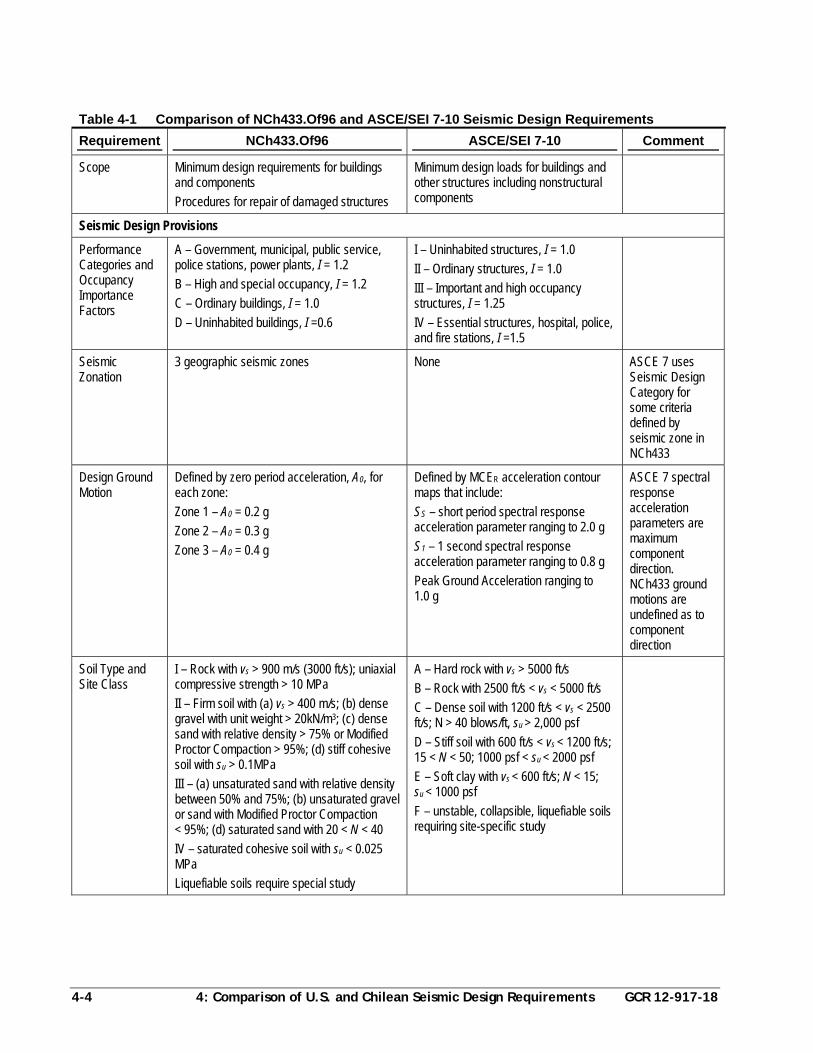
4-4 4: Comparison of U.S. and Chilean Seismic Design Requirements GCR 12-917-18
Table 4-1 Comparison of NCh433.Of96 and ASCE/SEI 7-10 Seismic Design Requirements
Requirement NCh433.Of96 ASCE/SEI 7-10 Comment
Scope Minimum design requirements for buildings and components
Procedures for repair of damaged structures
Minimum design loads for buildings and other structures including nonstructural components
Seismic Design Provisions
Performance Categories and Occupancy Importance Factors
A – Government, municipal, public service, police stations, power plants, I = 1.2
B – High and special occupancy, I = 1.2
C – Ordinary buildings, I = 1.0
D – Uninhabited buildings, I =0.6
I – Uninhabited structures, I = 1.0
II – Ordinary structures, I = 1.0
III – Important and high occupancy structures, I = 1.25
IV – Essential structures, hospital, police, and fire stations, I =1.5
Seismic Zonation
3 geographic seismic zones None ASCE 7 uses Seismic Design Category for some criteria defined by seismic zone in NCh433
Design Ground Motion
Defined by zero period acceleration, A0, for each zone:
Zone 1 – A0 = 0.2 g
Zone 2 – A0 = 0.3 g
Zone 3 – A0 = 0.4 g
Defined by MCER acceleration contour maps that include:
SS – short period spectral response acceleration parameter ranging to 2.0 g
S1 – 1 second spectral response acceleration parameter ranging to 0.8 g
Peak Ground Acceleration ranging to 1.0 g
ASCE 7 spectral response acceleration parameters are maximum component direction. NCh433 ground motions are undefined as to component direction
Soil Type and Site Class
I – Rock with vs > 900 m/s (3000 ft/s); uniaxial compressive strength > 10 MPa
II – Firm soil with (a) vs > 400 m/s; (b) dense gravel with unit weight > 20kN/m3; (c) dense sand with relative density > 75% or Modified Proctor Compaction > 95%; (d) stiff cohesive soil with su > 0.1MPa
III – (a) unsaturated sand with relative density between 50% and 75%; (b) unsaturated gravel or sand with Modified Proctor Compaction < 95%; (d) saturated sand with 20 < N < 40
IV – saturated cohesive soil with su < 0.025 MPa
Liquefiable soils require special study
A – Hard rock with vs > 5000 ft/s
B – Rock with 2500 ft/s < vs < 5000 ft/s
C – Dense soil with 1200 ft/s < vs < 2500 ft/s; N > 40 blows/ft, su > 2,000 psf
D – Stiff soil with 600 ft/s < vs < 1200 ft/s; 15 < N < 50; 1000 psf < su < 2000 psf
E – Soft clay with vs < 600 ft/s; N < 15; su < 1000 psf
F – unstable, collapsible, liquefiable soils requiring site-specific study
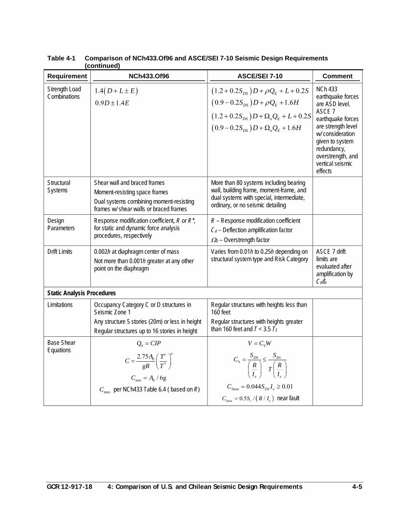
GCR 12-917-18 4: Comparison of U.S. and Chilean Seismic Design Requirements 4-5
Table 4-1 Comparison of NCh433.Of96 and ASCE/SEI 7-10 Seismic Design Requirements (continued)
Requirement NCh433.Of96 ASCE/SEI 7-10 Comment
Strength Load Combinations
1.4 D L E
0.9 1.4D E
1.2 0.2 0.2DS ES D Q L S
0.9 0.2 1.6DS ES D Q H
1.2 0.2 Ω 0.2DS o ES D Q L S
0.9 0.2 Ω 1.6DS o ES D Q H
NCh 433 earthquake forces are ASD level. ASCE 7 earthquake forces are strength level w/ consideration given to system redundancy, overstrength, and vertical seismic effects
Structural Systems
Shear wall and braced frames
Moment-resisting space frames
Dual systems combining moment-resisting frames w/ shear walls or braced frames
More than 80 systems including bearing wall, building frame, moment-frame, and dual systems with special, intermediate, ordinary, or no seismic detailing
Design Parameters
Response modification coefficient, R or R*, for static and dynamic force analysis procedures, respectively
R – Response modification coefficient
Cd – Deflection amplification factor
0 – Overstrength factor
Drift Limits 0.002h at diaphragm center of mass
Not more than 0.001h greater at any other point on the diaphragm
Varies from 0.01h to 0.25h depending on structural system type and Risk Category
ASCE 7 drift limits are evaluated after amplification by Cd/Ie
Static Analysis Procedures
Limitations Occupancy Category C or D structures in Seismic Zone 1
Any structure 5 stories (20m) or less in height
Regular structures up to 16 stories in height
Regular structures with heights less than 160 feet
Regular structures with heights greater than 160 feet and T < 3.5 TS
Base Shear Equations
0Q CIP
0*
2.75
g
nA T
CR T
0 / 6gminC A
maxC per NCh433 Table 6.4 ( based on R)
SV C W
1DS DS
e e
S SC
R RT
I I
0.044 0.01Smin DS eC S I
10.5 / /Smin eC S R I near fault
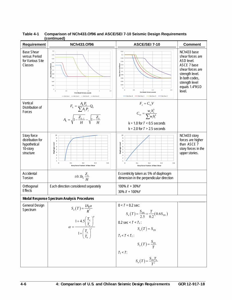
4-6 4: Comparison of U.S. and Chilean Seismic Design Requirements GCR 12-917-18
Table 4-1 Comparison of NCh433.Of96 and ASCE/SEI 7-10 Seismic Design Requirements (continued)
Requirement NCh433.Of96 ASCE/SEI 7-10 Comment
Base Shear versus Period for Various Site Classes
NCh433 base shear forces are ASD level. ASCE 7 base shear forces are strength level. In both codes, strength level equals 1.4*ASD level.
Vertical Distribution of Forces
0k k
kj j
A PF Q
A P
11 1k kk
Z ZA
H H
x vxF C V
kx x
vx ki i
w hC
w h
k = 1.0 for T < 0.5 seconds
k = 2.0 for T > 2.5 seconds
Story force distribution for hypothetical 10-story structure
NCh433 story forces are higher than ASCE 7 story forces in the upper stories.
Accidental Torsion 0.1 k
k
Zb
H
Eccentricity taken as 5% of diaphragm dimension in the perpendicular direction
Orthogonal Effects
Each direction considered separately 100% X + 30%Y
30% X + 100%Y
Modal Response Spectrum Analysis Procedures
General Design Spectrum 0
*a
IAS T
R
3
0
1 4.5
1
p
n
o
n
T
T
T
T
0 < T = 0.2 sec:
0.62.5 0.2
DSa DS
S TS T S
0.2 sec < T < Ts :
a DSS T S
Ts < T < TL :
1Da
SS T
T
TL < T:
12
D La
S TS T
T
0
0.02
0.04
0.06
0.08
0.1
0.12
0.14
0.16
0.18
0.2
0 0.5 1 1.5 2 2.5
Base Shear Coefficient
First Mode Period, seconds
Site Class I Site Class II Site Class III Site Class IV
0
0.02
0.04
0.06
0.08
0.1
0.12
0.14
0.16
0.18
0.2
0.22
0 0.5 1 1.5 2 2.5
Base Shear Coefficient
First Mode Period, seconds
Site Class B Site Class C Site Class D Site Class E
1
2
3
4
5
6
7
8
9
10
0 0.1 0.2 0.3 0.4
Diaphragm
Level
Story Force Fraction of Base Shear
1
2
3
4
5
6
7
8
9
10
0 0.1 0.2 0.3 0.4
Diaphragm
Level
Story Force Fraction of Base Shear
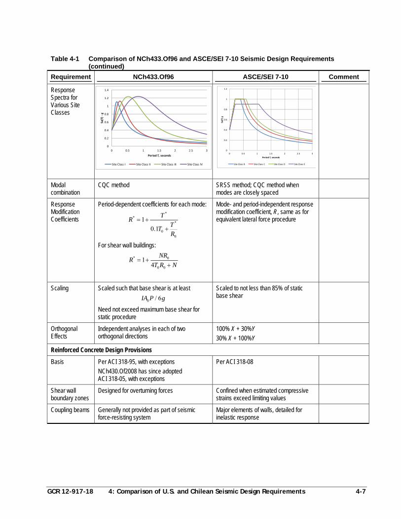
GCR 12-917-18 4: Comparison of U.S. and Chilean Seismic Design Requirements 4-7
Table 4-1 Comparison of NCh433.Of96 and ASCE/SEI 7-10 Seismic Design Requirements (continued)
Requirement NCh433.Of96 ASCE/SEI 7-10 Comment
Response Spectra for Various Site Classes
Modal combination
CQC method SRSS method; CQC method when modes are closely spaced
Response Modification Coefficients
Period-dependent coefficients for each mode: *
**
00
1
0.1
TR
TT
R
For shear wall buildings:
* 0
0 0
14
NRR
T R N
Mode- and period-independent response modification coefficient, R, same as for equivalent lateral force procedure
Scaling Scaled such that base shear is at least
0 / 6IA P g
Need not exceed maximum base shear for static procedure
Scaled to not less than 85% of static base shear
Orthogonal Effects
Independent analyses in each of two orthogonal directions
100% X + 30%Y
30% X + 100%Y
Reinforced Concrete Design Provisions
Basis Per ACI 318-95, with exceptions
NCh430.Of2008 has since adopted ACI 318-05, with exceptions
Per ACI 318-08
Shear wall boundary zones
Designed for overturning forces Confined when estimated compressive strains exceed limiting values
Coupling beams Generally not provided as part of seismic force-resisting system
Major elements of walls, detailed for inelastic response
0
0.2
0.4
0.6
0.8
1
1.2
1.4
0 0.5 1 1.5 2 2.5 3
Sa(T) ‐g
Period T, seconds
Site Class I Site Class II Site Class III Site Class IV
0
0.2
0.4
0.6
0.8
1
1.2
0 0.5 1 1.5 2 2.5 3
Sa(T) g
Period T, seconds
Site Class B Site Class C Site Class D Site Class E

GCR 12-917-18 5: Comparison of U.S. and Chilean Seismic Design Practice 5-1
Chapter 5
Comparison of U.S. and Chilean Seismic Design Practice
This chapter presents a comparative evaluation of a case study building used to
investigate and illustrate differences between U.S. and Chilean seismic design
practices. The subject building is a typical, mid-rise, reinforced concrete shear wall
building in Chile that was damaged as a result of the 2010 Maule earthquake. The
purpose of this comparison is to study how differences in code requirements and
design practices would result in differences in structural configuration and detailing.
The case study building was analyzed using both NCh433.Of96, Earthquake
Resistant Design of Buildings (INN, 1996) and ASCE/SEI 7-05, Minimum Design
Loads for Buildings and Other Structures (ASCE, 2006). It was then redesigned as a
hypothetical U.S. building, considering approximately the same seismic design
environment and the same floor plate size and shape, utilizing shear wall
configurations conforming to typical U.S. design practice. When needed, ACI
318-05, Building Code Requirements for Structural Concrete (ACI, 2005) was
referenced for concrete material design requirements.
5.1 Building Description
The Chilean case study building is a 10-story reinforced concrete shear wall building
that was designed and constructed in 1996. It has one basement level used for
parking, and is fairly typical of the type of construction used in mid-rise residential
occupancies in Chile. The case study site is located in Viña del Mar, and is
considered by NCh433.Of96 to be Seismic Zone 3. The building is assumed to have
been designed to the requirements of NCh433.Of96.
The building is rectangular in plan, measuring approximately 37 m long by 16 m
wide (121 feet by 52 feet). The typical floor plan is shown in Figure 5-1. The
basement story height is 3.6 m (11.5 feet), the first story height is 3.1 m (10 feet), and
the typical story height is 2.6 m (8.5 feet). Typical transverse wall elevations
showing the vertical configuration of the building are provided in Figure 5-2. As
shown in the figure, most walls have a setback at their base to provide improved
access to parking in the lower levels.
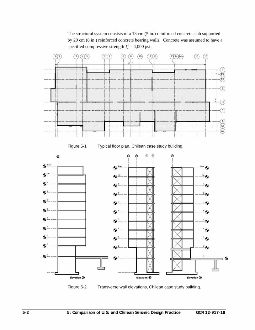
5-2 5: Comparison of U.S. and Chilean Seismic Design Practice GCR 12-917-18
The structural system consists of a 13 cm (5 in.) reinforced concrete slab supported
by 20 cm (8 in.) reinforced concrete bearing walls. Concrete was assumed to have a
specified compressive strength cf = 4,000 psi.
Figure 5-1 Typical floor plan, Chilean case study building.
Figure 5-2 Transverse wall elevations, Chilean case study building.
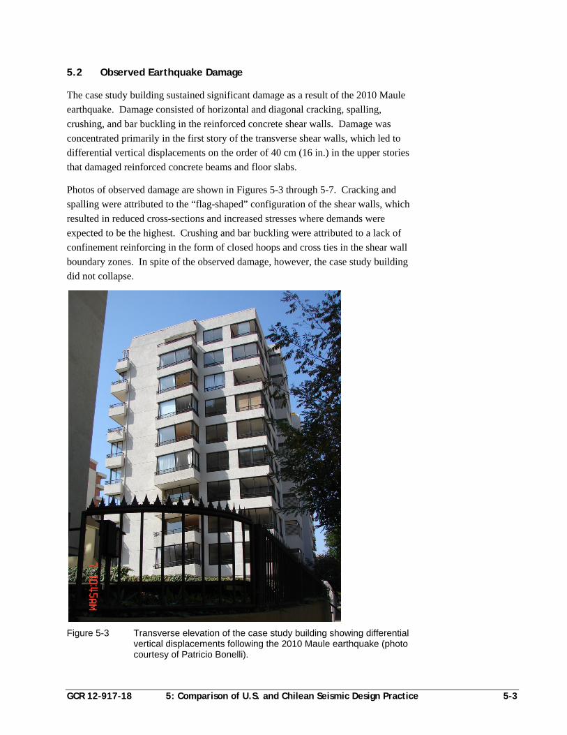
GCR 12-917-18 5: Comparison of U.S. and Chilean Seismic Design Practice 5-3
5.2 Observed Earthquake Damage
The case study building sustained significant damage as a result of the 2010 Maule
earthquake. Damage consisted of horizontal and diagonal cracking, spalling,
crushing, and bar buckling in the reinforced concrete shear walls. Damage was
concentrated primarily in the first story of the transverse shear walls, which led to
differential vertical displacements on the order of 40 cm (16 in.) in the upper stories
that damaged reinforced concrete beams and floor slabs.
Photos of observed damage are shown in Figures 5-3 through 5-7. Cracking and
spalling were attributed to the “flag-shaped” configuration of the shear walls, which
resulted in reduced cross-sections and increased stresses where demands were
expected to be the highest. Crushing and bar buckling were attributed to a lack of
confinement reinforcing in the form of closed hoops and cross ties in the shear wall
boundary zones. In spite of the observed damage, however, the case study building
did not collapse.
Figure 5-3 Transverse elevation of the case study building showing differential vertical displacements following the 2010 Maule earthquake (photo courtesy of Patricio Bonelli).
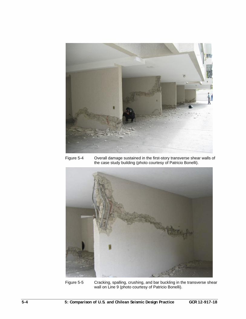
5-4 5: Comparison of U.S. and Chilean Seismic Design Practice GCR 12-917-18
Figure 5-4 Overall damage sustained in the first-story transverse shear walls of the case study building (photo courtesy of Patricio Bonelli).
Figure 5-5 Cracking, spalling, crushing, and bar buckling in the transverse shear wall on Line 9 (photo courtesy of Patricio Bonelli).
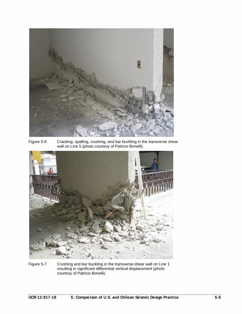
GCR 12-917-18 5: Comparison of U.S. and Chilean Seismic Design Practice 5-5
Figure 5-6 Cracking, spalling, crushing, and bar buckling in the transverse shear wall on Line 5 (photo courtesy of Patricio Bonelli).
Figure 5-7 Crushing and bar buckling in the transverse shear wall on Line 1 resulting in significant differential vertical displacement (photo courtesy of Patricio Bonelli).
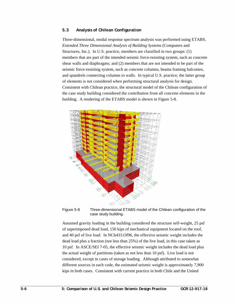
5-6 5: Comparison of U.S. and Chilean Seismic Design Practice GCR 12-917-18
5.3 Analysis of Chilean Configuration
Three-dimensional, modal response spectrum analysis was performed using ETABS,
Extended Three Dimensional Analysis of Building Systems (Computers and
Structures, Inc.). In U.S. practice, members are classified in two groups: (1)
members that are part of the intended seismic force-resisting system, such as concrete
shear walls and diaphragms; and (2) members that are not intended to be part of the
seismic force-resisting system, such as concrete columns, beams framing balconies,
and spandrels connecting columns to walls. In typical U.S. practice, the latter group
of elements is not considered when performing structural analysis for design.
Consistent with Chilean practice, the structural model of the Chilean configuration of
the case study building considered the contribution from all concrete elements in the
building. A rendering of the ETABS model is shown in Figure 5-8.
Figure 5-8 Three-dimensional ETABS model of the Chilean configuration of the case study building.
Assumed gravity loading in the building considered the structure self-weight, 25 psf
of superimposed dead load, 150 kips of mechanical equipment located on the roof,
and 40 psf of live load. In NCh433.Of96, the effective seismic weight includes the
dead load plus a fraction (not less than 25%) of the live load, in this case taken as
10 psf. In ASCE/SEI 7-05, the effective seismic weight includes the dead load plus
the actual weight of partitions (taken as not less than 10 psf). Live load is not
considered, except in cases of storage loading. Although attributed to somewhat
different sources in each code, the estimated seismic weight is approximately 7,900
kips in both cases. Consistent with current practice in both Chile and the United
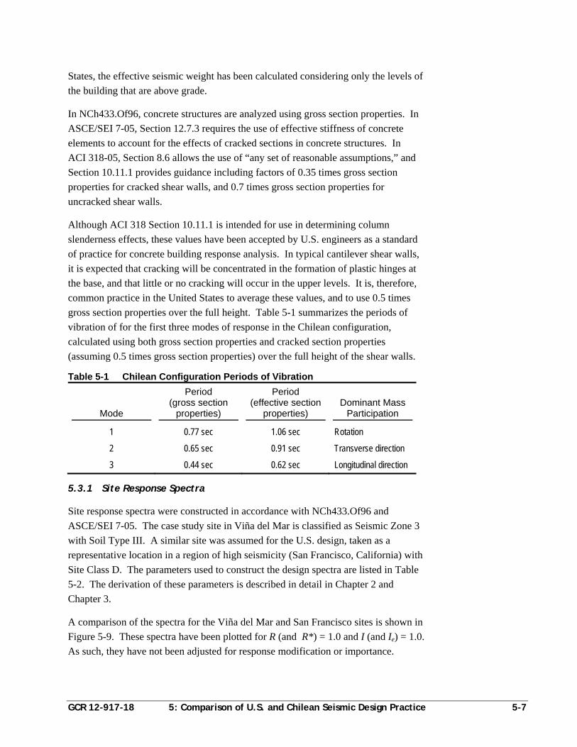
GCR 12-917-18 5: Comparison of U.S. and Chilean Seismic Design Practice 5-7
States, the effective seismic weight has been calculated considering only the levels of
the building that are above grade.
In NCh433.Of96, concrete structures are analyzed using gross section properties. In
ASCE/SEI 7-05, Section 12.7.3 requires the use of effective stiffness of concrete
elements to account for the effects of cracked sections in concrete structures. In
ACI 318-05, Section 8.6 allows the use of “any set of reasonable assumptions,” and
Section 10.11.1 provides guidance including factors of 0.35 times gross section
properties for cracked shear walls, and 0.7 times gross section properties for
uncracked shear walls.
Although ACI 318 Section 10.11.1 is intended for use in determining column
slenderness effects, these values have been accepted by U.S. engineers as a standard
of practice for concrete building response analysis. In typical cantilever shear walls,
it is expected that cracking will be concentrated in the formation of plastic hinges at
the base, and that little or no cracking will occur in the upper levels. It is, therefore,
common practice in the United States to average these values, and to use 0.5 times
gross section properties over the full height. Table 5-1 summarizes the periods of
vibration of for the first three modes of response in the Chilean configuration,
calculated using both gross section properties and cracked section properties
(assuming 0.5 times gross section properties) over the full height of the shear walls.
Table 5-1 Chilean Configuration Periods of Vibration
Mode
Period (gross section
properties)
Period (effective section
properties) Dominant Mass
Participation
1 0.77 sec 1.06 sec Rotation
2 0.65 sec 0.91 sec Transverse direction
3 0.44 sec 0.62 sec Longitudinal direction
5.3.1 Site Response Spectra
Site response spectra were constructed in accordance with NCh433.Of96 and
ASCE/SEI 7-05. The case study site in Viña del Mar is classified as Seismic Zone 3
with Soil Type III. A similar site was assumed for the U.S. design, taken as a
representative location in a region of high seismicity (San Francisco, California) with
Site Class D. The parameters used to construct the design spectra are listed in Table
5-2. The derivation of these parameters is described in detail in Chapter 2 and
Chapter 3.
A comparison of the spectra for the Viña del Mar and San Francisco sites is shown in
Figure 5-9. These spectra have been plotted for R (and R*) = 1.0 and I (and Ie) = 1.0.
As such, they have not been adjusted for response modification or importance.
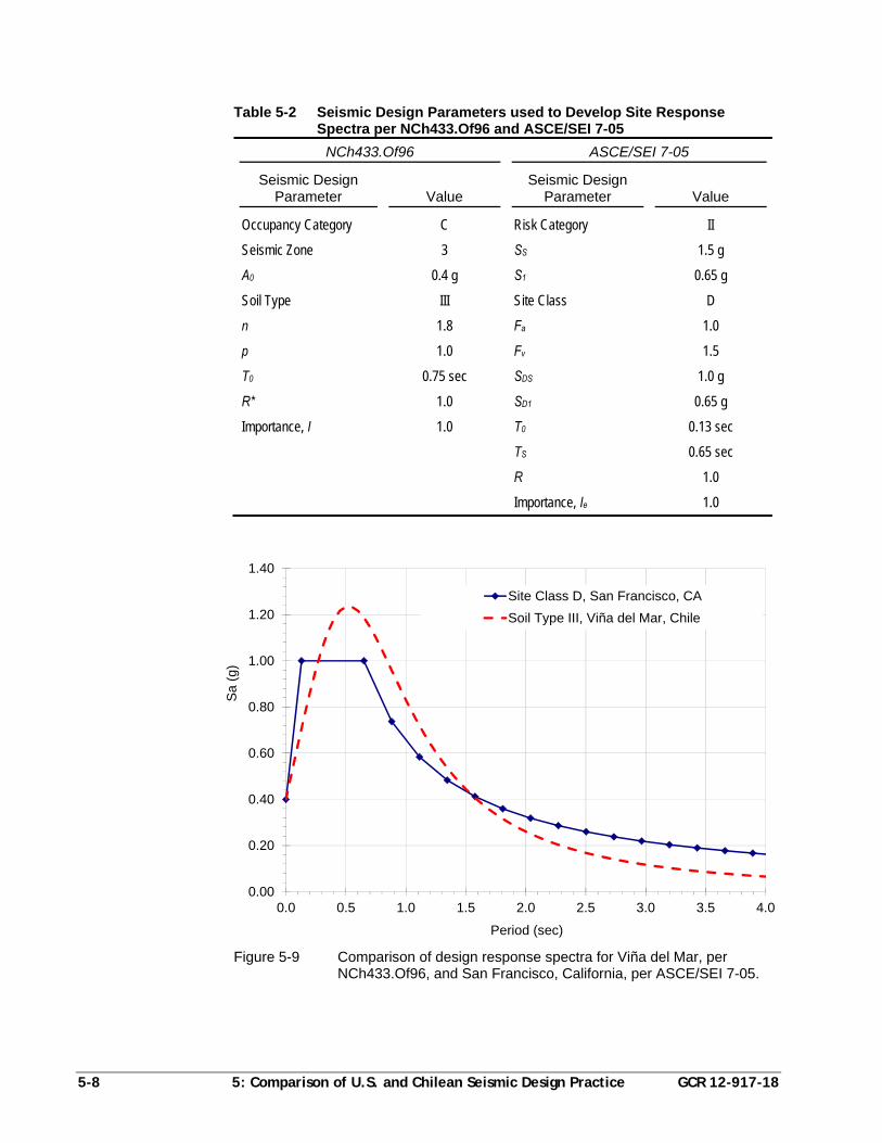
5-8 5: Comparison of U.S. and Chilean Seismic Design Practice GCR 12-917-18
Table 5-2 Seismic Design Parameters used to Develop Site Response Spectra per NCh433.Of96 and ASCE/SEI 7-05
NCh433.Of96 ASCE/SEI 7-05
Seismic Design Parameter Value
Seismic Design Parameter Value
Occupancy Category C Risk Category II
Seismic Zone 3 SS 1.5 g
A0 0.4 g S1 0.65 g
Soil Type III Site Class D
n 1.8 Fa 1.0
p 1.0 Fv 1.5
T0 0.75 sec SDS 1.0 g
R* 1.0 SD1 0.65 g
Importance, I 1.0 T0 0.13 sec
TS 0.65 sec
R 1.0
Importance, Ie 1.0
Figure 5-9 Comparison of design response spectra for Viña del Mar, per NCh433.Of96, and San Francisco, California, per ASCE/SEI 7-05.
0.00
0.20
0.40
0.60
0.80
1.00
1.20
1.40
0.0 0.5 1.0 1.5 2.0 2.5 3.0 3.5 4.0
Sa
(g)
Period (sec)
Site Class D, San Francisco, CA
Soil Type III, Viña del Mar, Chile
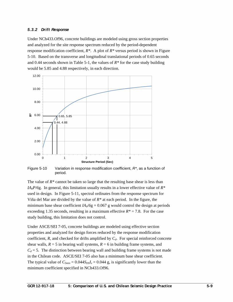
GCR 12-917-18 5: Comparison of U.S. and Chilean Seismic Design Practice 5-9
5.3.2 Drift Response
Under NCh433.Of96, concrete buildings are modeled using gross section properties
and analyzed for the site response spectrum reduced by the period-dependent
response modification coefficient, R*. A plot of R* versus period is shown in Figure
5-10. Based on the transverse and longitudinal translational periods of 0.65 seconds
and 0.44 seconds shown in Table 5-1, the values of R* for the case study building
would be 5.85 and 4.88 respectively, in each direction.
Figure 5-10 Variation in response modification coefficient, R*, as a function of period.
The value of R* cannot be taken so large that the resulting base shear is less than
IA0P/6g. In general, this limitation usually results in a lower effective value of R*
used in design. In Figure 5-11, spectral ordinates from the response spectrum for
Viña del Mar are divided by the value of R* at each period. In the figure, the
minimum base shear coefficient IA0/6g = 0.067 g would control the design at periods
exceeding 1.35 seconds, resulting in a maximum effective R* = 7.8. For the case
study building, this limitation does not control.
Under ASCE/SEI 7-05, concrete buildings are modeled using effective section
properties and analyzed for design forces reduced by the response modification
coefficient, R, and checked for drifts amplified by Cd. For special reinforced concrete
shear walls, R = 5 in bearing wall systems, R = 6 in building frame systems, and
Cd = 5. The distinction between bearing wall and building frame systems is not made
in the Chilean code. ASCE/SEI 7-05 also has a minimum base shear coefficient.
The typical value of CSmin = 0.044SDSIe = 0.044 g, is significantly lower than the
minimum coefficient specified in NCh433.Of96.
0.65, 5.85
0.44, 4.88
0.00
2.00
4.00
6.00
8.00
10.00
12.00
0 1 2 3 4 5
R*
Structure Period (Sec)
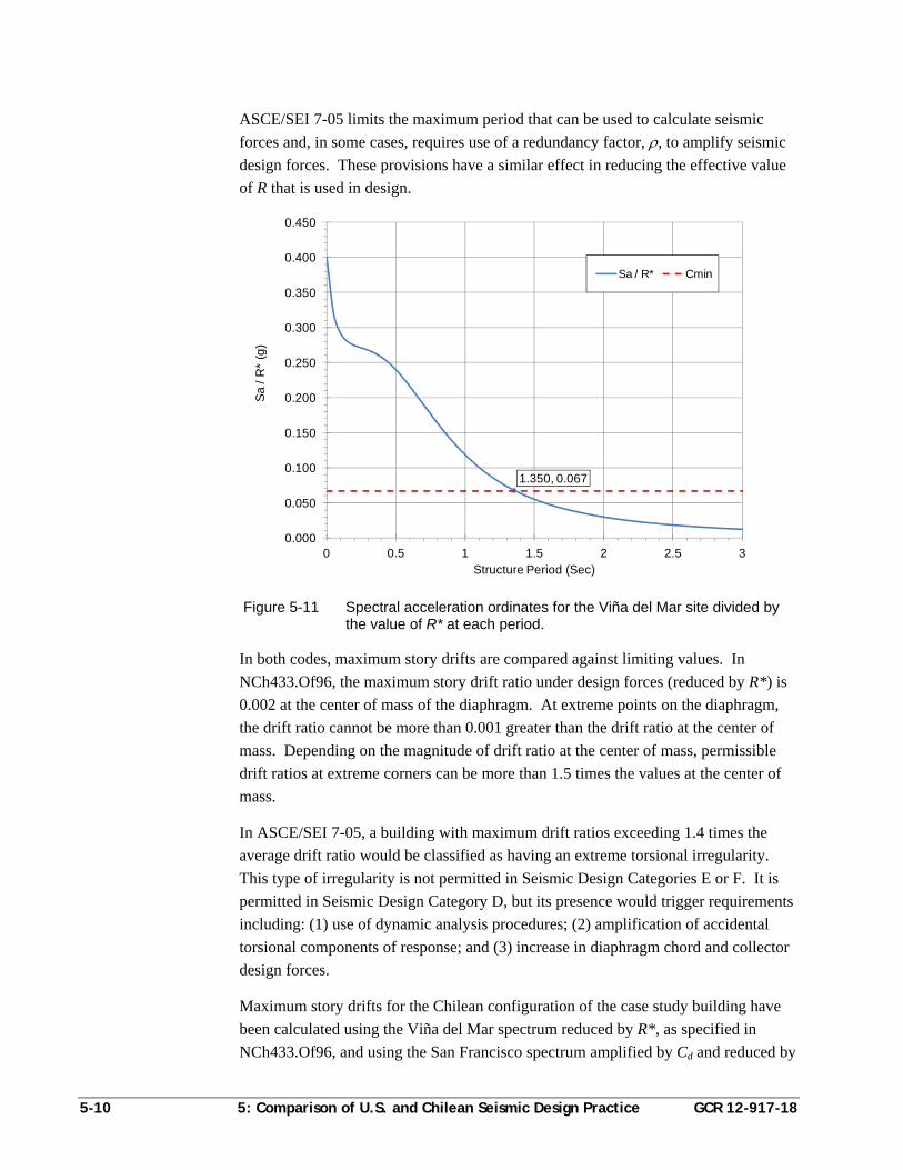
5-10 5: Comparison of U.S. and Chilean Seismic Design Practice GCR 12-917-18
ASCE/SEI 7-05 limits the maximum period that can be used to calculate seismic
forces and, in some cases, requires use of a redundancy factor, , to amplify seismic
design forces. These provisions have a similar effect in reducing the effective value
of R that is used in design.
Figure 5-11 Spectral acceleration ordinates for the Viña del Mar site divided by the value of R* at each period.
In both codes, maximum story drifts are compared against limiting values. In
NCh433.Of96, the maximum story drift ratio under design forces (reduced by R*) is
0.002 at the center of mass of the diaphragm. At extreme points on the diaphragm,
the drift ratio cannot be more than 0.001 greater than the drift ratio at the center of
mass. Depending on the magnitude of drift ratio at the center of mass, permissible
drift ratios at extreme corners can be more than 1.5 times the values at the center of
mass.
In ASCE/SEI 7-05, a building with maximum drift ratios exceeding 1.4 times the
average drift ratio would be classified as having an extreme torsional irregularity.
This type of irregularity is not permitted in Seismic Design Categories E or F. It is
permitted in Seismic Design Category D, but its presence would trigger requirements
including: (1) use of dynamic analysis procedures; (2) amplification of accidental
torsional components of response; and (3) increase in diaphragm chord and collector
design forces.
Maximum story drifts for the Chilean configuration of the case study building have
been calculated using the Viña del Mar spectrum reduced by R*, as specified in
NCh433.Of96, and using the San Francisco spectrum amplified by Cd and reduced by
1.350, 0.067
0.000
0.050
0.100
0.150
0.200
0.250
0.300
0.350
0.400
0.450
0 0.5 1 1.5 2 2.5 3
Sa
/ R
* (g
)
Structure Period (Sec)
Sa / R* Cmin
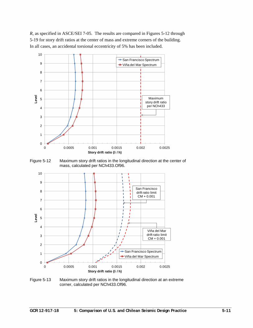
GCR 12-917-18 5: Comparison of U.S. and Chilean Seismic Design Practice 5-11
R, as specified in ASCE/SEI 7-05. The results are compared in Figures 5-12 through
5-19 for story drift ratios at the center of mass and extreme corners of the building.
In all cases, an accidental torsional eccentricity of 5% has been included.
Figure 5-12 Maximum story drift ratios in the longitudinal direction at the center of mass, calculated per NCh433.Of96.
Figure 5-13 Maximum story drift ratios in the longitudinal direction at an extreme corner, calculated per NCh433.Of96.
0
1
2
3
4
5
6
7
8
9
10
0 0.0005 0.001 0.0015 0.002 0.0025
Le
vel
Story drift ratio ( / h)
San Francisco Spectrum
Viña del Mar Spectrum
Maximumstory drift ratio per NCh433
0
1
2
3
4
5
6
7
8
9
10
0 0.0005 0.001 0.0015 0.002 0.0025
Le
vel
Story drift ratio ( / h)
San Francisco Spectrum
Viña del Mar Spectrum
San Francisco drift ratio limit CM + 0.001
Viña del Mar drift ratio limit CM + 0.001
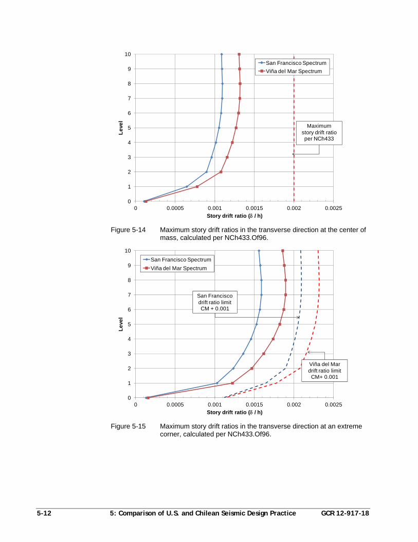
5-12 5: Comparison of U.S. and Chilean Seismic Design Practice GCR 12-917-18
Figure 5-14 Maximum story drift ratios in the transverse direction at the center of mass, calculated per NCh433.Of96.
Figure 5-15 Maximum story drift ratios in the transverse direction at an extreme corner, calculated per NCh433.Of96.
0
1
2
3
4
5
6
7
8
9
10
0 0.0005 0.001 0.0015 0.002 0.0025
Le
vel
Story drift ratio ( / h)
San Francisco Spectrum
Viña del Mar Spectrum
Maximumstory drift ratio per NCh433
0
1
2
3
4
5
6
7
8
9
10
0 0.0005 0.001 0.0015 0.002 0.0025
Le
vel
Story drift ratio ( / h)
San Francisco Spectrum
Viña del Mar Spectrum
San Francisco drift ratio limit CM + 0.001
Viña del Mar drift ratio limitCM+ 0.001
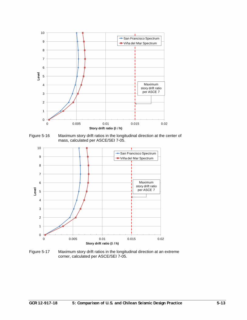
GCR 12-917-18 5: Comparison of U.S. and Chilean Seismic Design Practice 5-13
Figure 5-16 Maximum story drift ratios in the longitudinal direction at the center of mass, calculated per ASCE/SEI 7-05.
Figure 5-17 Maximum story drift ratios in the longitudinal direction at an extreme corner, calculated per ASCE/SEI 7-05.
0
1
2
3
4
5
6
7
8
9
10
0 0.005 0.01 0.015 0.02
Le
vel
Story drift ratio ( / h)
San Francisco Spectrum
Viña del Mar Spectrum
Maximumstory drift ratio per ASCE 7
0
1
2
3
4
5
6
7
8
9
10
0 0.005 0.01 0.015 0.02
Le
vel
Story drift ratio ( / h)
San Francisco Spectrum
Viña del Mar Spectrum
Maximumstory drift ratio per ASCE 7
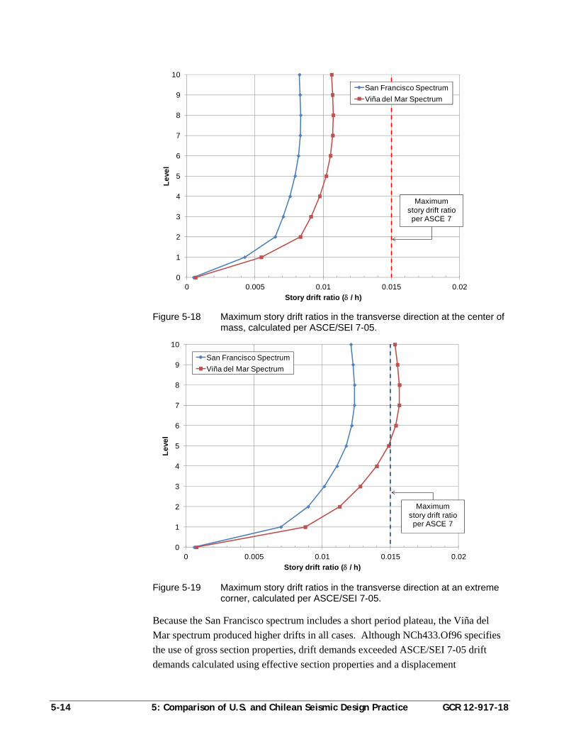
5-14 5: Comparison of U.S. and Chilean Seismic Design Practice GCR 12-917-18
Figure 5-18 Maximum story drift ratios in the transverse direction at the center of mass, calculated per ASCE/SEI 7-05.
Figure 5-19 Maximum story drift ratios in the transverse direction at an extreme corner, calculated per ASCE/SEI 7-05.
Because the San Francisco spectrum includes a short period plateau, the Viña del
Mar spectrum produced higher drifts in all cases. Although NCh433.Of96 specifies
the use of gross section properties, drift demands exceeded ASCE/SEI 7-05 drift
demands calculated using effective section properties and a displacement
0
1
2
3
4
5
6
7
8
9
10
0 0.005 0.01 0.015 0.02
Le
vel
Story drift ratio ( / h)
San Francisco Spectrum
Viña del Mar Spectrum
Maximumstory drift ratio per ASCE 7
0
1
2
3
4
5
6
7
8
9
10
0 0.005 0.01 0.015 0.02
Le
vel
Story drift ratio ( / h)
San Francisco Spectrum
Viña del Mar Spectrum
Maximumstory drift ratio per ASCE 7
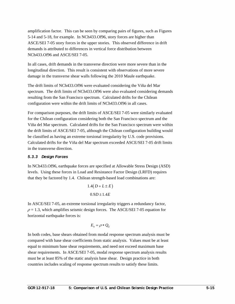
GCR 12-917-18 5: Comparison of U.S. and Chilean Seismic Design Practice 5-15
amplification factor. This can be seen by comparing pairs of figures, such as Figures
5-14 and 5-18, for example. In NCh433.Of96, story forces are higher than
ASCE/SEI 7-05 story forces in the upper stories. This observed difference in drift
demands is attributed to differences in vertical force distribution between
NCh433.Of96 and ASCE/SEI 7-05.
In all cases, drift demands in the transverse direction were more severe than in the
longitudinal direction. This result is consistent with observations of more severe
damage in the transverse shear walls following the 2010 Maule earthquake.
The drift limits of NCh433.Of96 were evaluated considering the Viña del Mar
spectrum. The drift limits of NCh433.Of96 were also evaluated considering demands
resulting from the San Francisco spectrum. Calculated drifts for the Chilean
configuration were within the drift limits of NCh433.Of96 in all cases.
For comparison purposes, the drift limits of ASCE/SEI 7-05 were similarly evaluated
for the Chilean configuration considering both the San Francisco spectrum and the
Viña del Mar spectrum. Calculated drifts for the San Francisco spectrum were within
the drift limits of ASCE/SEI 7-05, although the Chilean configuration building would
be classified as having an extreme torsional irregularity by U.S. code provisions.
Calculated drifts for the Viña del Mar spectrum exceeded ASCE/SEI 7-05 drift limits
in the transverse direction.
5.3.3 Design Forces
In NCh433.Of96, earthquake forces are specified at Allowable Stress Design (ASD)
levels. Using these forces in Load and Resistance Factor Design (LRFD) requires
that they be factored by 1.4. Chilean strength-based load combinations are:
1.4 D L E
0.9 1.4D E
In ASCE/SEI 7-05, an extreme torsional irregularity triggers a redundancy factor,
= 1.3, which amplifies seismic design forces. The ASCE/SEI 7-05 equation for
horizontal earthquake forces is:
h EE Q
In both codes, base shears obtained from modal response spectrum analysis must be
compared with base shear coefficients from static analysis. Values must be at least
equal to minimum base shear requirements, and need not exceed maximum base
shear requirements. In ASCE/SEI 7-05, modal response spectrum analysis results
must be at least 85% of the static analysis base shear. Design practice in both
countries includes scaling of response spectrum results to satisfy these limits.
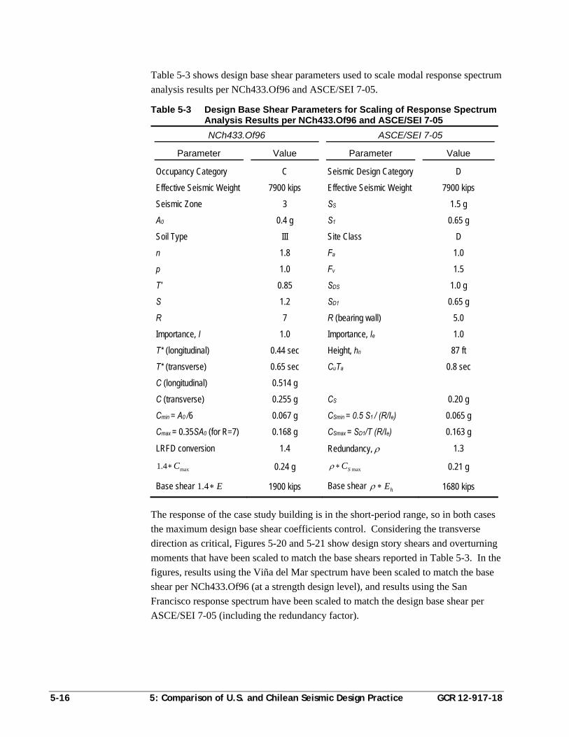
5-16 5: Comparison of U.S. and Chilean Seismic Design Practice GCR 12-917-18
Table 5-3 shows design base shear parameters used to scale modal response spectrum
analysis results per NCh433.Of96 and ASCE/SEI 7-05.
Table 5-3 Design Base Shear Parameters for Scaling of Response Spectrum Analysis Results per NCh433.Of96 and ASCE/SEI 7-05
NCh433.Of96 ASCE/SEI 7-05
Parameter Value Parameter Value
Occupancy Category C Seismic Design Category D
Effective Seismic Weight 7900 kips Effective Seismic Weight 7900 kips
Seismic Zone 3 SS 1.5 g
A0 0.4 g S1 0.65 g
Soil Type III Site Class D
n 1.8 Fa 1.0
p 1.0 Fv 1.5
T′ 0.85 SDS 1.0 g
S 1.2 SD1 0.65 g
R 7 R (bearing wall) 5.0
Importance, I 1.0 Importance, Ie 1.0
T* (longitudinal) 0.44 sec Height, hn 87 ft
T* (transverse) 0.65 sec CuTa 0.8 sec
C (longitudinal) 0.514 g
C (transverse) 0.255 g CS 0.20 g
Cmin = A0 /6 0.067 g CSmin = 0.5 S1 / (R/Ie) 0.065 g
Cmax = 0.35SA0 (for R=7) 0.168 g CSmax = SD1/T (R/Ie) 0.163 g
LRFD conversion 1.4 Redundancy, 1.3
max1.4 C 0.24 g maxSC 0.21 g
Base shear 1.4 E 1900 kips Base shear hE 1680 kips
The response of the case study building is in the short-period range, so in both cases
the maximum design base shear coefficients control. Considering the transverse
direction as critical, Figures 5-20 and 5-21 show design story shears and overturning
moments that have been scaled to match the base shears reported in Table 5-3. In the
figures, results using the Viña del Mar spectrum have been scaled to match the base
shear per NCh433.Of96 (at a strength design level), and results using the San
Francisco response spectrum have been scaled to match the design base shear per
ASCE/SEI 7-05 (including the redundancy factor).
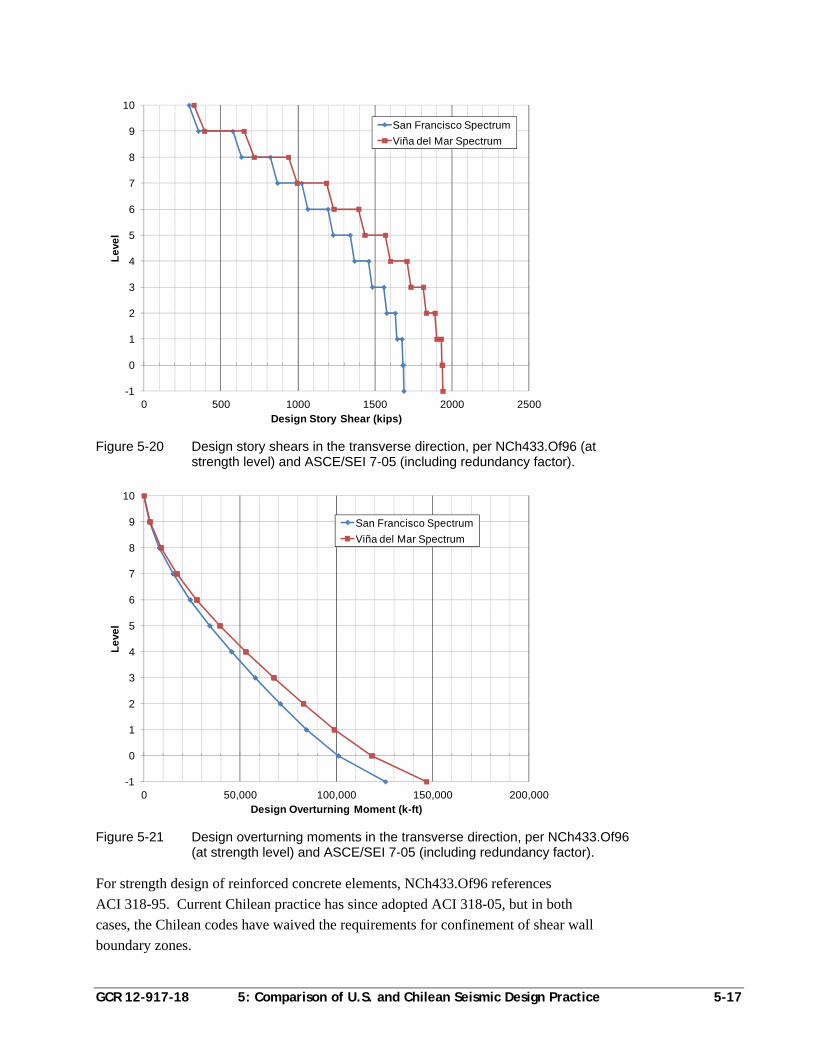
GCR 12-917-18 5: Comparison of U.S. and Chilean Seismic Design Practice 5-17
Figure 5-20 Design story shears in the transverse direction, per NCh433.Of96 (at strength level) and ASCE/SEI 7-05 (including redundancy factor).
Figure 5-21 Design overturning moments in the transverse direction, per NCh433.Of96 (at strength level) and ASCE/SEI 7-05 (including redundancy factor).
For strength design of reinforced concrete elements, NCh433.Of96 references
ACI 318-95. Current Chilean practice has since adopted ACI 318-05, but in both
cases, the Chilean codes have waived the requirements for confinement of shear wall
boundary zones.
-1
0
1
2
3
4
5
6
7
8
9
10
0 500 1000 1500 2000 2500
Le
vel
Design Story Shear (kips)
San Francisco Spectrum
Viña del Mar Spectrum
-1
0
1
2
3
4
5
6
7
8
9
10
0 50,000 100,000 150,000 200,000
Le
vel
Design Overturning Moment (k-ft)
San Francisco Spectrum
Viña del Mar Spectrum
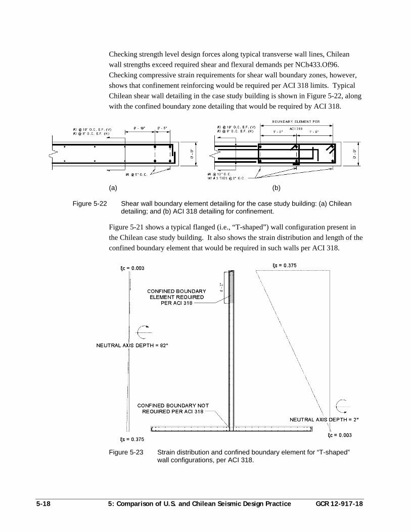
5-18 5: Comparison of U.S. and Chilean Seismic Design Practice GCR 12-917-18
Checking strength level design forces along typical transverse wall lines, Chilean
wall strengths exceed required shear and flexural demands per NCh433.Of96.
Checking compressive strain requirements for shear wall boundary zones, however,
shows that confinement reinforcing would be required per ACI 318 limits. Typical
Chilean shear wall detailing in the case study building is shown in Figure 5-22, along
with the confined boundary zone detailing that would be required by ACI 318.
(a) (b)
Figure 5-22 Shear wall boundary element detailing for the case study building: (a) Chilean detailing; and (b) ACI 318 detailing for confinement.
Figure 5-21 shows a typical flanged (i.e., “T-shaped”) wall configuration present in
the Chilean case study building. It also shows the strain distribution and length of the
confined boundary element that would be required in such walls per ACI 318.
Figure 5-23 Strain distribution and confined boundary element for “T-shaped” wall configurations, per ACI 318.
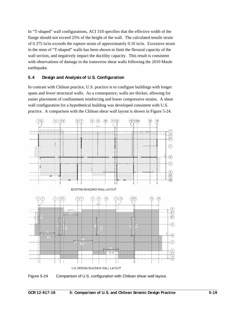
GCR 12-917-18 5: Comparison of U.S. and Chilean Seismic Design Practice 5-19
In “T-shaped” wall configurations, ACI 318 specifies that the effective width of the
flange should not exceed 25% of the height of the wall. The calculated tensile strain
of 0.375 in/in exceeds the rupture strain of approximately 0.10 in/in. Excessive strain
in the stem of “T-shaped” walls has been shown to limit the flexural capacity of the
wall section, and negatively impact the ductility capacity. This result is consistent
with observations of damage in the transverse shear walls following the 2010 Maule
earthquake.
5.4 Design and Analysis of U.S. Configuration
In contrast with Chilean practice, U.S. practice is to configure buildings with longer
spans and fewer structural walls. As a consequence, walls are thicker, allowing for
easier placement of confinement reinforcing and lower compressive strains. A shear
wall configuration for a hypothetical building was developed consistent with U.S.
practice. A comparison with the Chilean shear wall layout is shown in Figure 5-24.
Figure 5-24 Comparison of U.S. configuration with Chilean shear wall layout.
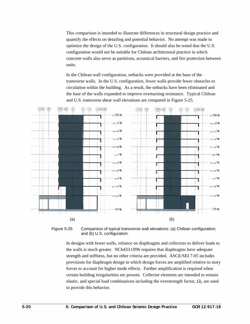
5-20 5: Comparison of U.S. and Chilean Seismic Design Practice GCR 12-917-18
This comparison is intended to illustrate differences in structural design practice and
quantify the effects on detailing and potential behavior. No attempt was made to
optimize the design of the U.S. configuration. It should also be noted that the U.S.
configuration would not be suitable for Chilean architectural practice in which
concrete walls also serve as partitions, acoustical barriers, and fire protection between
units.
In the Chilean wall configuration, setbacks were provided at the base of the
transverse walls. In the U.S. configuration, fewer walls provide fewer obstacles to
circulation within the building. As a result, the setbacks have been eliminated and
the base of the walls expanded to improve overturning resistance. Typical Chilean
and U.S. transverse shear wall elevations are compared in Figure 5-25.
(a) (b)
Figure 5-25 Comparison of typical transverse wall elevations: (a) Chilean configuration; and (b) U.S. configuration.
In designs with fewer walls, reliance on diaphragms and collectors to deliver loads to
the walls is much greater. NCh433.Of96 requires that diaphragms have adequate
strength and stiffness, but no other criteria are provided. ASCE/SEI 7-05 includes
provisions for diaphragm design in which design forces are amplified relative to story
forces to account for higher mode effects. Further amplification is required when
certain building irregularities are present. Collector elements are intended to remain
elastic, and special load combinations including the overstrength factor, 0, are used
to provide this behavior.
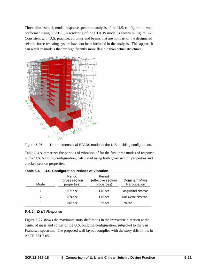
GCR 12-917-18 5: Comparison of U.S. and Chilean Seismic Design Practice 5-21
Three-dimensional, modal response spectrum analysis of the U.S. configuration was
performed using ETABS. A rendering of the ETABS model is shown in Figure 5-26.
Consistent with U.S. practice, columns and beams that are not part of the designated
seismic force-resisting system have not been included in the analysis. This approach
can result in models that are significantly more flexible than actual structures.
Figure 5-26 Three-dimensional ETABS model of the U.S. building configuration.
Table 5-4 summarizes the periods of vibration of for the first three modes of response
in the U.S. building configuration, calculated using both gross section properties and
cracked section properties.
Table 5-4 U.S. Configuration Periods of Vibration
Mode
Period (gross section
properties)
Period (effective section
properties) Dominant Mass
Participation
1 0.76 sec 1.06 sec Longitudinal direction
2 0.74 sec 1.05 sec Transverse direction
3 0.68 sec 0.93 sec Rotation
5.4.1 Drift Response
Figure 5-27 shows the maximum story drift ratios in the transverse direction at the
center of mass and corner of the U.S. building configuration, subjected to the San
Francisco spectrum. The proposed wall layout complies with the story drift limits in
ASCE/SEI 7-05.
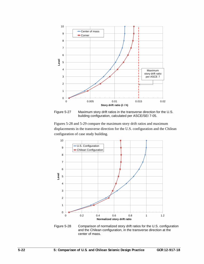
5-22 5: Comparison of U.S. and Chilean Seismic Design Practice GCR 12-917-18
Figure 5-27 Maximum story drift ratios in the transverse direction for the U.S. building configuration, calculated per ASCE/SEI 7-05.
Figures 5-28 and 5-29 compare the maximum story drift ratios and maximum
displacements in the transverse direction for the U.S. configuration and the Chilean
configuration of case study building.
Figure 5-28 Comparison of normalized story drift ratios for the U.S. configuration and the Chilean configuration, in the transverse direction at the center of mass.
0
1
2
3
4
5
6
7
8
9
10
0 0.005 0.01 0.015 0.02
Le
vel
Story drift ratio ( / h)
Center of mass
Corner
Maximumstory drift ratio per ASCE 7
0
1
2
3
4
5
6
7
8
9
10
0 0.2 0.4 0.6 0.8 1 1.2
Lev
el
Normalized story drift ratio
U.S. Configuration
Chilean Configuration
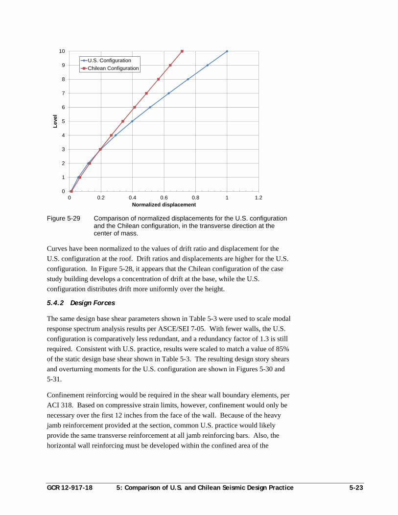
GCR 12-917-18 5: Comparison of U.S. and Chilean Seismic Design Practice 5-23
Figure 5-29 Comparison of normalized displacements for the U.S. configuration and the Chilean configuration, in the transverse direction at the center of mass.
Curves have been normalized to the values of drift ratio and displacement for the
U.S. configuration at the roof. Drift ratios and displacements are higher for the U.S.
configuration. In Figure 5-28, it appears that the Chilean configuration of the case
study building develops a concentration of drift at the base, while the U.S.
configuration distributes drift more uniformly over the height.
5.4.2 Design Forces
The same design base shear parameters shown in Table 5-3 were used to scale modal
response spectrum analysis results per ASCE/SEI 7-05. With fewer walls, the U.S.
configuration is comparatively less redundant, and a redundancy factor of 1.3 is still
required. Consistent with U.S. practice, results were scaled to match a value of 85%
of the static design base shear shown in Table 5-3. The resulting design story shears
and overturning moments for the U.S. configuration are shown in Figures 5-30 and
5-31.
Confinement reinforcing would be required in the shear wall boundary elements, per
ACI 318. Based on compressive strain limits, however, confinement would only be
necessary over the first 12 inches from the face of the wall. Because of the heavy
jamb reinforcement provided at the section, common U.S. practice would likely
provide the same transverse reinforcement at all jamb reinforcing bars. Also, the
horizontal wall reinforcing must be developed within the confined area of the
0
1
2
3
4
5
6
7
8
9
10
0 0.2 0.4 0.6 0.8 1 1.2
Lev
el
Normalized displacement
U.S. Configuration
Chilean Configuration
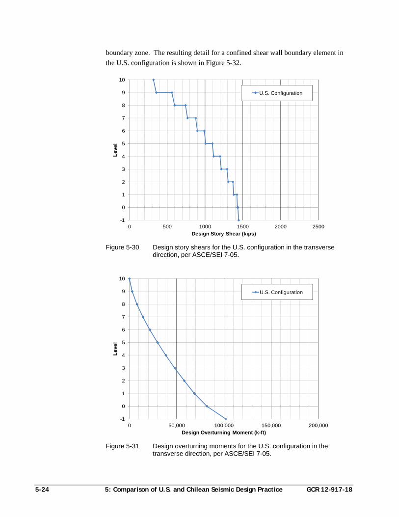
5-24 5: Comparison of U.S. and Chilean Seismic Design Practice GCR 12-917-18
boundary zone. The resulting detail for a confined shear wall boundary element in
the U.S. configuration is shown in Figure 5-32.
Figure 5-30 Design story shears for the U.S. configuration in the transverse direction, per ASCE/SEI 7-05.
Figure 5-31 Design overturning moments for the U.S. configuration in the transverse direction, per ASCE/SEI 7-05.
-1
0
1
2
3
4
5
6
7
8
9
10
0 500 1000 1500 2000 2500
Le
vel
Design Story Shear (kips)
U.S. Configuration
-1
0
1
2
3
4
5
6
7
8
9
10
0 50,000 100,000 150,000 200,000
Le
vel
Design Overturning Moment (k-ft)
U.S. Configuration
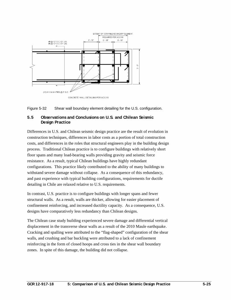
GCR 12-917-18 5: Comparison of U.S. and Chilean Seismic Design Practice 5-25
Figure 5-32 Shear wall boundary element detailing for the U.S. configuration.
5.5 Observations and Conclusions on U.S. and Chilean Seismic Design Practice
Differences in U.S. and Chilean seismic design practice are the result of evolution in
construction techniques, differences in labor costs as a portion of total construction
costs, and differences in the roles that structural engineers play in the building design
process. Traditional Chilean practice is to configure buildings with relatively short
floor spans and many load-bearing walls providing gravity and seismic force
resistance. As a result, typical Chilean buildings have highly redundant
configurations. This practice likely contributed to the ability of many buildings to
withstand severe damage without collapse. As a consequence of this redundancy,
and past experience with typical building configurations, requirements for ductile
detailing in Chile are relaxed relative to U.S. requirements.
In contrast, U.S. practice is to configure buildings with longer spans and fewer
structural walls. As a result, walls are thicker, allowing for easier placement of
confinement reinforcing, and increased ductility capacity. As a consequence, U.S.
designs have comparatively less redundancy than Chilean designs.
The Chilean case study building experienced severe damage and differential vertical
displacement in the transverse shear walls as a result of the 2010 Maule earthquake.
Cracking and spalling were attributed to the “flag-shaped” configuration of the shear
walls, and crushing and bar buckling were attributed to a lack of confinement
reinforcing in the form of closed hoops and cross ties in the shear wall boundary
zones. In spite of this damage, the building did not collapse.
5-26 5: Comparison of U.S. and Chilean Seismic Design Practice GCR 12-917-18
Evaluation of the Chilean configuration of the case study building for both
NCh433.Of96 and ASCE/SEI 7-05 requirements, and comparison of the Chilean
design with a hypothetical U.S. design, yielded the following observations:
Chilean analysis of reinforced concrete structures considers gross section
properties and all structural elements in the building, while U.S. practice
considers effective section properties and only those elements designated as part
of the seismic force-resisting system.
Unreduced response spectra for NCh433.Of96 Soil Type III and ASCE/SEI 7-05
Site Class D, in regions of high seismicity, are similar in shape and magnitude,
although the Chilean spectrum does not include a short period plateau. Chilean
provisions do, however, include a maximum seismic design coefficient that
varies with structural system.
Permissible limits in NCh433.Of96 regarding drift at the diaphragm center of
mass relative to the diaphragm edge would be classified as an extreme torsional
irregularity in ASCE/SEI 7-05.
NCh433.Of96 story forces (as a percentage of base shear) are higher than
ASCE/SEI 7-05 story forces in the upper stories.
When applied to the same structure, drift demands resulting from an application
of NCh433.Of96 were more severe than drift demands per ASCE/SEI 7-05, even
considering differences such as the use of effective section properties and a
displacement amplification factor in ASCE/SEI 7-05. It appears that buildings
meeting NCh433.Of96 drift requirements would also satisfy ASCE/SEI 7-05 drift
requirements.
Although attributed to somewhat different sources in NCh433.Of96 and
ASCE/SEI 7-05, the estimated seismic weight is approximately the same in each
code.
Typical design base shear formulas, adjusted to a strength basis, produced nearly
identical design base shear coefficients.
The minimum base shear coefficient specified in NCh433.Of96 is approximately
50% higher than the minimum base shear coefficient specified in ASCE/SEI 7-05
for ordinary structures. When adjusted to a strength basis, it is approximately
double.
ACI 318-05 provisions would have resulted in the need for confinement
reinforcing in the shear wall boundary zones of the Chilean configuration,
especially in the case of unsymmetric flanged walls (i.e., “T-shaped” walls).
GCR 12-917-18 References A-1
References
ACI, 2011, Building Code Requirements for Structural Concrete, ACI 318-11,
American Concrete Institute, Farmington Hills, Michigan.
ACI, 2008, Building Code Requirements for Structural Concrete, ACI 318-08,
American Concrete Institute, Farmington Hills, Michigan.
ACI, 2005, Building Code Requirements for Structural Concrete, ACI 318-05,
American Concrete Institute, Farmington Hills, Michigan.
ACI, 1983, Building Code Requirements for Reinforced Concrete, ACI 318-83,
American Concrete Institute, Farmington Hills, Michigan.
ASCE, 2010, Minimum Design Loads for Buildings and Other Structures, ASCE/SEI
7-10, American Society of Civil Engineers, Reston, Virginia.
ASCE, 2006, Minimum Design Loads for Buildings and Other Structures, ASCE/SEI
7-05, including Supplement No. 1, American Society of Civil Engineers,
Reston, Virginia.
ASCE, 2000, Minimum Design Loads for Buildings and Other Structures, ASCE
7-98, American Society of Civil Engineers, Reston, Virginia.
ATC, 1978, Tentative Provisions for the Development of Seismic Regulations for
Buildings, ATC 3-06, Applied Technology Council, Redwood City,
California.
Boroschek, R., Soto, P., and Leon, R., 2010, Maule Region Earthquake, February 27,
2010, Mw = 8.8, RENADIC Report 10/08 Rev. 2, University of Chile,
Santiago, Chile.
BSSC, 1985, NEHRP Recommended Provisions for the Development of Seismic
Regulations for New Buildings, Part 1: Provisions, FEMA 95, prepared by
the Building Seismic Safety Council for the Federal Emergency Management
Agency, Washington, D.C.
BSSC, 1998, NEHRP Recommended Provisions for Seismic Regulations for New
Buildings and Other Structures, Part 1: Provisions, FEMA 302, 1997
Edition, prepared by the Building Seismic Safety Council for the Federal
Emergency Management Agency, Washington, D.C.
CIA, 2012, The World Factbook, Central Intelligence Agency, last updated April 11,
2012, https://www.cia.gov/library/publications/the-world-factbook/geos
/ci.html.
A-2 References GCR 12-917-18
DIN, 1953, Concrete and Reinforced Concrete, DIN 1045, Beuth Verlag GmbH for
the Deutsches Institut für Normung, Berlin, Germany.
EERI, 2010, “The Mw 8.8 Chile Earthquake of February 27, 2010,” EERI Newsletter,
June 2010, Vol. 44, No. 6.
EERI, 1986, “The Chile Earthquake of March 3, 1985,” Earthquake Spectra, Vol. 2,
No. 2.
Engineers Association of Chile, 2010, Informe Técnico Del Colegio De Ingenieros
De Chile A.G. Sobre Los Efectos Del Terremoto En Edificaciones De Las
Regiones Metropolitana, V Y VI, Colegio de Ingenieros de Chile (Engineers
Association of Chile), accessed June 30, 2012, http://www.ingenieros.cl
/index.php?option=com_content&task=view&id=441&Itemid=451.
FEMA, 2009, Quantification of Building Seismic Performance Factors, FEMA
P-695, prepared by Applied Technology Council for the Federal Emergency
Management Agency, Washington, D.C.
ICBO, 1994, Uniform Building Code, International Conference of Building Officials,
Whittier, California.
ICBO, 1988, Uniform Building Code, International Conference of Building Officials,
Whittier, California.
ICBO, 1982, Uniform Building Code, International Conference of Building Officials,
Whittier, California.
ICC, 2006, International Building Code, International Code Council, Washington,
D.C.
ICC, 2000, International Building Code, International Code Council, Washington,
D.C.
INN, 2008, Reinforced Concrete Design and Analysis Requirements,
NCh430.Of2008, Instituto Nacional de Normalización, Santiago, Chile.
INN, 2006, Reinforcing Steel – Hot-Rolled Rebar for Reinforced Concrete,
NCh204.Of2006, Instituto Nacional de Normalización, Santiago, Chile.
INN, 1996, Earthquake Resistant Design of Buildings, NCh433.Of96, Instituto
Nacional de Normalización, Santiago, Chile.
University of Chile, 2012, “2010 1002271 Terremoto del Maule,” Terremotos de
Chile / Earthquakes of Chile, accessed on March 22, 2012, http://terremotos
.ing.uchile.cl/registros/164.
USGS, 2012, Magnitude 8.8 - Offshore Bio-Bio, Chile, United States Geological
Survey, last updated April 11, 2012, http://earthquake.usgs.gov/earthquakes
/eqinthenews/2010/us2010tfan/#summary.
GCR 12-917-18 References A-3
USGS, 2011, Pager - M 8.8 - Offshore Maule, Chile, United States Geological
Survey, last updated September 19, 2011, http://earthquake.usgs.gov
/earthquakes/pager/events/us/2010tfan/index.html.
USGS, 2009, Historic World Earthquakes, United States Geological Survey, last
updated November 23, 2009, http://earthquake.usgs.gov/earthquakes/world
/historical_country.php.
Wood, S.L., 1991, “Performance of Reinforced Concrete Buildings During the 1985
Chile Earthquake: Implications for the Design of Structural Walls,”
Earthquake Spectra, Vol. 7, No. 4, pp. 607-638.
Wood, S.L., Moehle, J.P., and Wight, J.K., 1987, The 1985 Chile Earthquake:
Observations on Earthquake-Resistant Construction in Viña del Mar,
University of Illinois at Urbana-Champaign, Urbana, Illinois.

GCR 12-917-18 Project Participants B-1
Project Participants
National Institute of Standards and Technology
John (Jack) R. Hayes, Jr. Engineering Laboratory (MS8604) National Institute of Standards and Technology 100 Bureau Drive Gaithersburg, Maryland 20899 www.NEHRP.gov
Steven L. McCabe Engineering Laboratory (MS8604) National Institute of Standards and Technology 100 Bureau Drive Gaithersburg, Maryland 20899 www.NEHRP.gov
NEHRP Consultants Joint Venture
APPLIED TECHNOLOGY COUNCIL 201 Redwood Shores Parkway, Suite 240 Redwood City, California 94065 www.ATCouncil.org
CONSORTIUM OF UNIVERSITIES FOR RESEARCH IN EARTHQUAKE ENGINEERING 1301 S. 46th Street, Building 420 Richmond, California 94804 www.CUREE.org
Joint Venture Management Committee
James R. Harris J.R. Harris & Company 1775 Sherman Street, Suite 1525 Denver, Colorado 80203 Robert Reitherman Consortium of Universities for Research in Earthquake Engineering 1301 S. 46th Street, Building 420 Richmond, California 94804
Christopher Rojahn Applied Technology Council 201 Redwood Shores Parkway, Suite 240 Redwood City, California, 94065 Andrew Whittaker University at Buffalo Dept. of Civil, Structural, and Environ. Engin. 230 Ketter Hall Buffalo, New York 14260
Joint Venture Program Committee
Jon A. Heintz (Program Manager) Applied Technology Council 201 Redwood Shores Parkway, Suite 240 Redwood City, California 94065 Michael Constantinou University at Buffalo Dept. of Civil, Structural, and Environ. Engin. 132 Ketter Hall Buffalo, New York 14260
C.B. Crouse URS Corporation 1501 4th Avenue, Suite 1400 Seattle, Washington 98101 William T. Holmes Rutherford & Chekene 55 Second Street, Suite 600 San Francisco, California 94105
B-2 Project Participants GCR 12-917-18
Jack Moehle University of California, Berkeley Dept. of Civil and Environmental Engineering 325 Davis Hall – MC 1792 Berkeley, California 94720
James R. Harris (ex-officio) Andrew Whittaker (ex-officio)
Project Technical Committee
Ronald O. Hamburger (Technical Director) Simpson Gumpertz & Heger The Landmark @ One Market, Suite 600 San Francisco, California 94105 Patricio Bonelli Patricio Bonelli y Asociados LTDA. Montana 853, Of. 401 Viña del Mar, Chile
Rene Lagos Rene Lagos y Asociados Magdalena 140, Of. 2402 Santiago, Chile Loring A. Wyllie, Jr. Degenkolb Engineers 235 Montgomery Street, Suite 500 San Francisco, California 94104
Working Group Members
Ady Aviram Simpson Gumpertz & Heger The Landmark @ One Market, Suite 600 San Francisco, California 94105
Jose A. Flores Ruiz Degenkolb Engineers 235 Montgomery Street, Suite 500 San Francisco, California 94104
Recommended