DC InverterAqua Mini Chillers & Fan Coil Units
INVERTER
1703-1C1702
iOS Version Android Version
Midea CAC After-service Application
iOS Version
Midea CAC News Application
Add.: Midea Headquarters Building, 6 Midea Avenue, Shunde, Foshan, Guangdong, China
Postal code: 528311
Tel: +86-757-26338346 Fax: +86-757-22390205
cac.midea.com global.midea.com
Note: Product speci�cations change from time to time as product improvements and
developments are released and may vary from those in this document.
Commercial Air Conditioner Division
Midea Group
Commercial Air Conditioners 2017/2018

There are three production bases: Shunde, Chongqing and Hefei.
MCAC Shunde: 38 product lines focusing on VRF, Split Products, Heat Pump Water Heaters, and AHU/FCU.
MCAC Chongqing: 14 product lines focusing on Water Cooled Centrifugal/Screw/Scroll Chillers, Air Cooled Screw/Scroll Chillers,
and AHU/FCU.
MCAC Hefei: 11 product lines focusing on VRF, Chillers, and Heat Pump Water Heaters.
Midea CACMidea CAC is a key division of the Midea Group, a leading producer of consumer appliances and provider of heating, ventilation
and air conditioning solutions. Midea CAC has continued with the tradition of innovation upon which it was founded, and
emerged as a global leader in the HVAC industry. A strong drive for advancement has created a groundbreaking R&D
department that has placed Midea CAC at the forefront of a competitive field. Through these independent efforts and joint
cooperation with other global enterprises, Midea has supplied thousands of innovative solutions to customers worldwide.
2016 Strategic alliance between Midea and Italy’s Clivet
2015 JV with Carrier in China in chiller field, launched the unitary all DC inverter type Aqua Mini Chiller
2014 Launched the DC Inverter Fan Coil Units
2013 Launched the super high efficiency centrifugal chiller with full falling film technology
2012 Formed Midea-Carrier JV.Company in India and HK
2010 Built the 3rd manufacturing base in Hefei
2009 Launched the unitary fixed type Aqua Mini Chiller
2008 Launched the split digital type Aqua Mini Chiller
2006 Launched the first VSD centrifugal chiller
2004 Acquired MGRE entered the chiller industry
2001 Cooperated with Copeland to develop the digital scroll VRF system
2000 Developed the first inverter VRF with Toshiba
1999 Entered the CAC field
Midea Company Introduction
Midea CAC Introduction
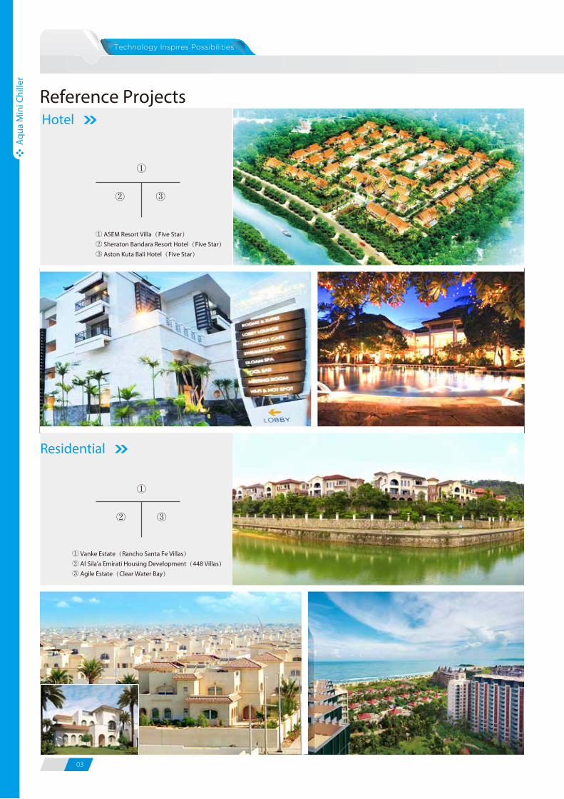
Hotel
① ASEM Resort Villa(Five Star)② Sheraton Bandara Resort Hotel(Five Star)③ Aston Kuta Bali Hotel(Five Star)
①
② ③
Residential
① Vanke Estate(Rancho Santa Fe Villas)② Al Sila'a Emirati Housing Development(448 Villas)③ Agile Estate(Clear Water Bay)
①
② ③
03 04
Aqu
a M
ini C
hille
r
Aqu
a M
ini C
hille
r
Contents
0507
11
14
1521
25
30
32
34
38
39
41
42
Aqua Mini ChillerFeatures
Speci�cations
Unit Dimensions
Fan Coil UnitsCassette Series
Duct Series
Wall Mounted
Ceiling & Floor
Dimensions
Control Devices
Accessories
Application of Central Control & BMS Control
Selection Software
Reference Projects
INVERTER
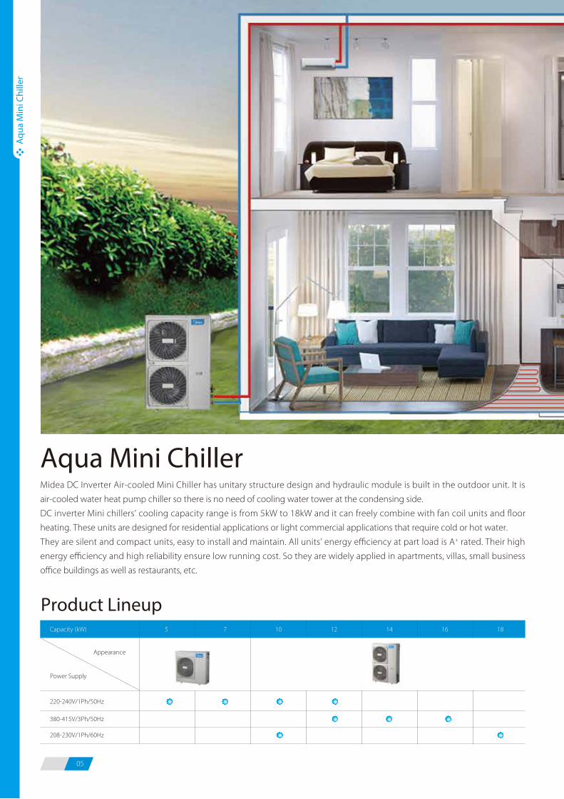
05 06
Midea DC Inverter Air-cooled Mini Chiller has unitary structure design and hydraulic module is built in the outdoor unit. It is
air-cooled water heat pump chiller so there is no need of cooling water tower at the condensing side.
DC inverter Mini chillers’ cooling capacity range is from 5kW to 18kW and it can freely combine with fan coil units and floor
heating. These units are designed for residential applications or light commercial applications that require cold or hot water.
They are silent and compact units, easy to install and maintain. All units’ energy efficiency at part load is A+ rated. Their high
energy efficiency and high reliability ensure low running cost. So they are widely applied in apartments, villas, small business
office buildings as well as restaurants, etc.
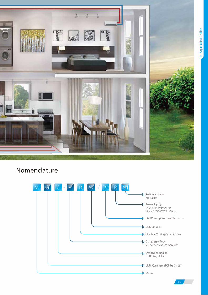
Refrigerant typeN1: R410A
M - /G C V W N116 RD2
Design Series CodeC: Unitary chiller
Compressor TypeV: Inverter scroll compressor
Midea
Power SupplyR: 380-415V/3Ph/50HzNone: 220-240V/1Ph/50Hz
D2: DC compressor and fan motor
Outdoor Unit
Nominal Cooling Capacity (kW)
Light Commercial Chiller System
Nomenclature
Aqu
a M
ini C
hille
r
Aqu
a M
ini C
hille
r
Product Lineup
Appearance
Power Supply
Capacity (kW) 5 7 10 12 14 16 18
380-415V/3Ph/50Hz
208-230V/1Ph/60Hz
208-230V/1Ph/60Hz
220-240V/1Ph/50Hz
Aqua Mini Chiller
05 06
Midea DC Inverter Air-cooled Mini Chiller has unitary structure design and hydraulic module is built in the outdoor unit. It is
air-cooled water heat pump chiller so there is no need of cooling water tower at the condensing side.
DC inverter Mini chillers’ cooling capacity range is from 5kW to 18kW and it can freely combine with fan coil units and floor
heating. These units are designed for residential applications or light commercial applications that require cold or hot water.
They are silent and compact units, easy to install and maintain. All units’ energy efficiency at part load is A+ rated. Their high
energy efficiency and high reliability ensure low running cost. So they are widely applied in apartments, villas, small business
office buildings as well as restaurants, etc.
Refrigerant typeN1: R410A
M - /G C V W N116 RD2
Design Series CodeC: Unitary chiller
Compressor TypeV: Inverter scroll compressor
Midea
Power SupplyR: 380-415V/3Ph/50HzNone: 220-240V/1Ph/50Hz
D2: DC compressor and fan motor
Outdoor Unit
Nominal Cooling Capacity (kW)
Light Commercial Chiller System
Nomenclature
Aqu
a M
ini C
hille
r
Aqu
a M
ini C
hille
r
Product Lineup
Appearance
Power Supply
Capacity (kW) 5 7 10 12 14 16 18
380-415V/3Ph/50Hz
208-230V/1Ph/60Hz
208-230V/1Ph/60Hz
220-240V/1Ph/50Hz
Aqua Mini Chiller
07 08
Aqu
a M
ini C
hille
r
Aqu
a M
ini C
hille
r
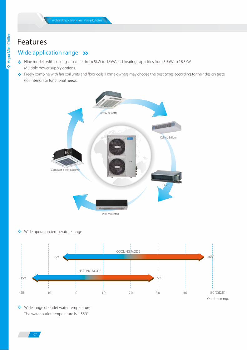
FeaturesWide application range
Nine models with cooling capacities from 5kW to 18kW and heating capacities from 5.5kW to 18.5kW.
Multiple power supply options.
Freely combine with fan coil units and floor coils. Home owners may choose the best types according to their design taste
(for interior) or functional needs.
4 way cassette
Compact 4 way cassette
Wall mounted
Duct
Ceiling & floor
Wide operation temperature range
COOLING MODE
HEATING MODE
Outdoor temp.
46°C
27°C
-5°C
-15°C
0 1 0 2 0 3 0 4 0 5 0 °C(D.B.)-10-20
The new designed window fins enlarge the heat-exchanging area, decrease the air resistance, save more power and enhance
heat exchange performance.
Hydrophilic film fins and inner-threaded copper pipes optimize heat exchange efficiency.
The specially coated blue fins enhance durability and protect against corrosion from air, water and other corrosive agents,
assures a longer coil service life.
Wide range of outlet water temperature
The water outlet temperature is 4-55°C.
Mot
or s
peed
(RPM
)
System pressure
DC inverter stepless adjustment
AC inverter multistep adjustment
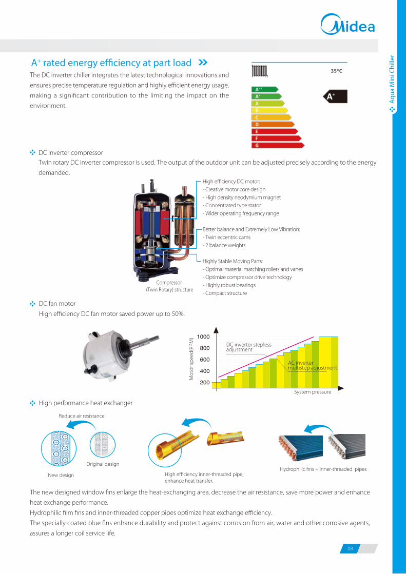
DC fan motor
High efficiency DC fan motor saved power up to 50%.
New design
Original design
High efficiency inner-threaded pipe, enhance heat transfer.
Reduce air resistance
Hydrophilic fins + inner-threaded pipes
High performance heat exchanger
A+ rated energy e�ciency at part loadThe DC inverter chiller integrates the latest technological innovations and
ensures precise temperature regulation and highly efficient energy usage,
making a significant contribution to the limiting the impact on the
environment.
Compressor (Twin Rotary) structure
High efficiency DC motor:- Creative motor core design- High density neodymium magnet- Concentrated type stator- Wider operating frequency range
Better balance and Extremely Low Vibration:- Twin eccentric cams- 2 balance weights
Highly Stable Moving Parts:- Optimal material matching rollers and vanes- Optimize compressor drive technology- Highly robust bearings- Compact structure
Twin rotary DC inverter compressor is used. The output of the outdoor unit can be adjusted precisely according to the energy
demanded.
DC inverter compressor
07 08
Aqu
a M
ini C
hille
r
Aqu
a M
ini C
hille
r
FeaturesWide application range
Nine models with cooling capacities from 5kW to 18kW and heating capacities from 5.5kW to 18.5kW.
Multiple power supply options.
Freely combine with fan coil units and floor coils. Home owners may choose the best types according to their design taste
(for interior) or functional needs.
4 way cassette
Compact 4 way cassette
Wall mounted
Duct
Ceiling & floor
Wide operation temperature range
COOLING MODE
HEATING MODE
Outdoor temp.
46°C
27°C
-5°C
-15°C
0 1 0 2 0 3 0 4 0 5 0 °C(D.B.)-10-20
The new designed window fins enlarge the heat-exchanging area, decrease the air resistance, save more power and enhance
heat exchange performance.
Hydrophilic film fins and inner-threaded copper pipes optimize heat exchange efficiency.
The specially coated blue fins enhance durability and protect against corrosion from air, water and other corrosive agents,
assures a longer coil service life.
Wide range of outlet water temperature
The water outlet temperature is 4-55°C.
Mot
or s
peed
(RPM
)
System pressure
DC inverter stepless adjustment
AC inverter multistep adjustment
DC fan motor
High efficiency DC fan motor saved power up to 50%.
New design
Original design
High efficiency inner-threaded pipe, enhance heat transfer.
Reduce air resistance
Hydrophilic fins + inner-threaded pipes
High performance heat exchanger
A+ rated energy e�ciency at part loadThe DC inverter chiller integrates the latest technological innovations and
ensures precise temperature regulation and highly efficient energy usage,
making a significant contribution to the limiting the impact on the
environment.
Compressor (Twin Rotary) structure
High efficiency DC motor:- Creative motor core design- High density neodymium magnet- Concentrated type stator- Wider operating frequency range
Better balance and Extremely Low Vibration:- Twin eccentric cams- 2 balance weights
Highly Stable Moving Parts:- Optimal material matching rollers and vanes- Optimize compressor drive technology- Highly robust bearings- Compact structure
Twin rotary DC inverter compressor is used. The output of the outdoor unit can be adjusted precisely according to the energy
demanded.
DC inverter compressor
09 10
Aqu
a M
ini C
hille
r
Aqu
a M
ini C
hille
r
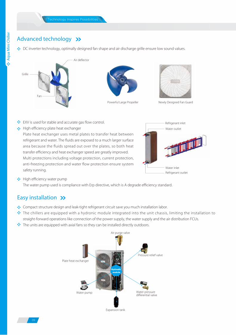
DC inverter technology, optimally designed fan shape and air discharge grille ensure low sound values.
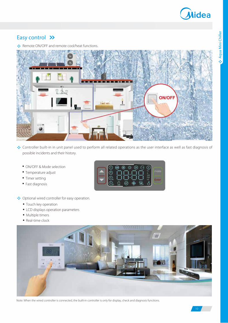
Easy controlRemote ON/OFF and remote cool/heat functions.
Optional wired controller for easy operation.
Note: When the wired controller is connected, the built-in controller is only for display, check and diagnosis functions.
Controller built-in in unit panel used to perform all related operations as the user interface as well as fast diagnosis of
possible incidents and their history.
EXV is used for stable and accurate gas flow control.
High efficiency plate heat exchanger
Plate heat exchanger uses metal plates to transfer heat between
refrigerant and water. The fluids are exposed to a much larger surface
area because the fluids spread out over the plates, so both heat
transfer efficiency and heat exchanger speed are greatly improved.
Multi protections including voltage protection, current protection,
anti-freezing protection and water flow protection ensure system
safety running.
High efficiency water pump
The water pump used is compliance with Erp directive, which is A degrade efficiency standard.
Easy installationCompact structure design and leak-tight refrigerant circuit save you much installation labor.
The chillers are equipped with a hydronic module integrated into the unit chassis, limiting the installation to
straight-forward operations like connection of the power supply, the water supply and the air distribution FCUs.
The units are equipped with axial fans so they can be installed directly outdoors.
Advanced technology
Powerful Large Propeller Newly Designed Fan Guard
Fan
Air deflector
Grille
Refrigerant inlet
Refrigerant outlet
Water inlet
Water outlet
Pressure relief valve
Plate heat exchanger
Air purge valve
Water pressure differential valve
Expansion tank
Water pump
Hydraulic module
ON/OFF & Mode selection
Temperature adjust
Timer setting
Fast diagnosis
Touch key operationLCD displays operation parametersMultiple timersReal-time clock
09 10
Aqu
a M
ini C
hille
r
Aqu
a M
ini C
hille
r
DC inverter technology, optimally designed fan shape and air discharge grille ensure low sound values.
Easy controlRemote ON/OFF and remote cool/heat functions.
Optional wired controller for easy operation.
Note: When the wired controller is connected, the built-in controller is only for display, check and diagnosis functions.
Controller built-in in unit panel used to perform all related operations as the user interface as well as fast diagnosis of
possible incidents and their history.
EXV is used for stable and accurate gas flow control.
High efficiency plate heat exchanger
Plate heat exchanger uses metal plates to transfer heat between
refrigerant and water. The fluids are exposed to a much larger surface
area because the fluids spread out over the plates, so both heat
transfer efficiency and heat exchanger speed are greatly improved.
Multi protections including voltage protection, current protection,
anti-freezing protection and water flow protection ensure system
safety running.
High efficiency water pump
The water pump used is compliance with Erp directive, which is A degrade efficiency standard.
Easy installationCompact structure design and leak-tight refrigerant circuit save you much installation labor.
The chillers are equipped with a hydronic module integrated into the unit chassis, limiting the installation to
straight-forward operations like connection of the power supply, the water supply and the air distribution FCUs.
The units are equipped with axial fans so they can be installed directly outdoors.
Advanced technology
Powerful Large Propeller Newly Designed Fan Guard
Fan
Air deflector
Grille
Refrigerant inlet
Refrigerant outlet
Water inlet
Water outlet
Pressure relief valve
Plate heat exchanger
Air purge valve
Water pressure differential valve
Expansion tank
Water pump
Hydraulic module
ON/OFF & Mode selection
Temperature adjust
Timer setting
Fast diagnosis
Touch key operationLCD displays operation parametersMultiple timersReal-time clock
11 12
Aqu
a M
ini C
hille
r
Aqu
a M
ini C
hille
r
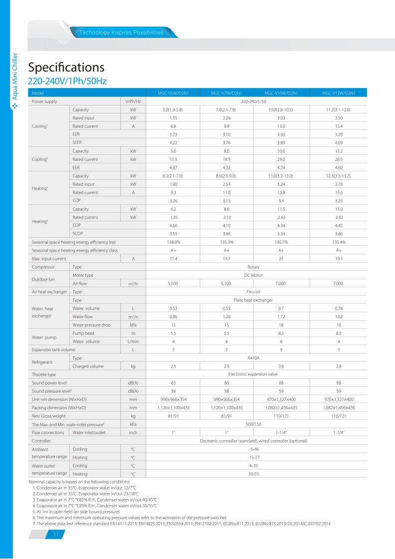
Speci�cations220-240V/1Ph/50Hz 380-415V/3Ph/50Hz
MGC-V5W/D2N1 MGC-V7W/D2N1 MGC-V10W/D2N1 MGC-V12W/D2N1
V/Ph/Hz
Capacity kW 5.0(1.9-5.8) 7.0(2.1-7.8) 10.0(2.9-10.5) 11.2(3.1-12.0)
Rated input kW 1.55 2.26 3.03 3.50
Rated current A 6.8 9.9 13.0 15.4
3.23 3.10 3.30 3.20
4.22 3.76 3.89 4.09
Capacity kW 5.6 8.0 10.6 12.2
Rated current kW 11.5 18.5 23.0 26.5
EER 4.87 4.32 4.24 4.60
Capacity kW 6.2(2.1-7.0) 8.0(2.3-9.0) 11.0(3.2-12.0) 12.3(3.3-13.2)
Rated input kW 1.90 2.54 3.24 3.78
Rated current A 8.3 11.0 13.8 16.6
3.26 3.15 3.4 3.25
Capacity kW 6.2 8.6 11.5 13.0
Rated current kW 1.35 2.10 2.65 2.92
4.60 4.10 4.34 4.45
3.55 3.46 3.34 3.46
138.9% 135.3% 130.7% 135.4%
A+ A+ A+ A+
A 11.4 13.7 25 19.1
Compressor
Air flow m3/h 5,100 5,100 7,000 7,000
Air heat exchanger
Water volume L 0.53 0.53 0.7 0.78
Water flow m3/h 0.86 1.20 1.72 1.92
Water pressure drop kPa 15 15 18 18
Pump head m 5.5 5.5 8.5 8.5
Water volume L/min 4 4 4 4
L 2 2 3 3
Charged volume kg 2.5 2.5 2.8 2.8
dB(A) 63 66 68 68
dB(A) 58 58 59 59
mm 990×966×354 990×966×354 970×1,327×400 970×1,327×400
mm 1,120×1,100×435 1,120×1,100×435 1,082×1,456×435 1,082×1,456×435
kg 81/91 81/91 110/121 110/121
kPa
Pipe connections Water inlet/outlet inch 1’’ 1’’ 1-1/4“ 1-1/4“
Cooling °C
Heating °C
Cooling °C
Heating °C
The Max. and Min. wate rinlet pressure6
Packing dimension (W×H×D)
Net/ Gross weight
Controller
Type
Motor type
COP
COP
SCOP
Model
Power supply
Seasonal space heating energy efficiency class
Seasonal space heating energy efficiency (ηs)
Type
Max. input current
Outdoor fan
Cooling1
Cooling2
Heating3
Heating4
Electronic expansion valveThrottle type
Type
Water pump
EER
SEER
RefrigerantType
Expansion tank volume
Plate heat exchanger
Fin-coil
Water heat
exchanger
4-20
30-55
R410A
Ambient
temperature range
Water outlet
temperature range
Sound power level
Sound pressure level5
Unit net dimension (W×H×D)
220-240/1/50
500/150
DC Motor
-5-46
-15-27
Rotary
Electronic controller (standard), wired controller (optional)
Nominal capacity is based on the following conditions: 1. Condenser air in 35°C. Evaporator water in/out 12/7°C 2. Condenser air in 35°C. Evaporator water in/out 23/18°C 3. Evaporator air in 7°C °C85% R.H., Condenser water in/out 40/45°C 4. Evaporator air in 7°C °C85% R.H., Condenser water in/out 30/35°C 5. At 1m in open field fan side (sound pressure) 6. The maximum and minimum operating pressure values refer to the activation of the pressure switches 7. The above data test reference standard EN14511:2013; EN14825:2013; EN50564:2011; EN12102:2011; (EU)No:811:2013; (EU)No:813:2013; OJ 2014/C 207/02:2014
Nominal capacity is based on the following conditions: 1. Condenser air in 35°C, Evaporator water in/out 12/7°C 2. Condenser air in 35°C, Evaporator water in/out 23/18°C 3. Evaporator air in 7°C °C85% R.H., Condenser water in/out 40/45°C 4. Evaporator air in 7°C °C85% R.H., Condenser water in/out 30/35°C 5. At 1m in open field fan side (sound pressure) 6. The maximum and minimum operating pressure values refer to the activation of the pressure switches 7. The above data test reference standard EN14511:2013; EN14825:2013; EN50564:2011; EN12102:2011; (EU)No:811:2013; (EU)No:813:2013; OJ 2014/C 207/02:2014
MGC-V12W/D2RN1 MGC-V14W/D2RN1 MGC-V16W/D2RN1
V/Ph/Hz
Capacity kW 11.2(3.1-12.0) 12.5(3.3-14.0) 14.5(3.5-15.5)
Rated input kW 3.38 3.91 4.68
Rated current A 5.5 6.4 7.7
3.31 3.20 3.10
4.16 4.27 4.38
Capacity kW 12.2 14.2 15.6
Rated input W 2.60 3.10 3.60
4.70 4.58 4.33
Capacity kW 12.3(3.3-13.2) 13.8(3.5-15.4) 16.0(3.7-17.0)
Rated input kW 3.72 4.25 4.85
Rated current A 6.1 7.0 8.0
3.31 3.25 3.30
Capacity kW 13.0 15.1 16.5
Rated input kW 2850 3350 3920
4.56 4.51 4.21
3.66 3.78 3.39
143.5% 148.3% 132.6%
A+ A+ A+
A 8.9 9.6 10.1
Compressor
Air flow m3/h 7,000 7,000 7,000
Air heat exchanger
Water volume L 0.78 0.78 1.06
Water flow m3/h 1.92 2.15 2.49
Water pressure drop kPa 18 18 19
Pump head m 8.5 8.5 8.5
Water volume L/min 4 4 4
L 3 3 3
Charged volume kg 2.8 2.9 3.2
dB(A) 68 70 72
dB(A) 62 62 62
mm
mm
kg 110/121 111/122 111/122
kPa
Pipe connections Water inlet/outlet inch
Cooling °C
Heating °C
Cooling °C
Heating °C
The Max. and Min. water inlet pressure6
Controller
Model
Power supply
Seasonal space heating energy efficiency (ηs)
Cooling1
Cooling2
Heating3
Heating4
EER
SEER
RefrigerantType
Type
Outdoor fanMotor type
Type
Water heat
exchanger
Type
Water pump
Expansion tank volume
Electronic expansion valveThrottle type
Sound power level
Sound pressure level5
Unit net dimension (W×H×D)
Packing dimension (W×H×D)
Net/ Gross weight
-5-46
-15-27
4-20
30-55
Electronic controller (standard), wired controller (optional)
Ambient
temperature range
Water outlet
temperature range
EER
Rotary
DC motor
Fin-coil
COP
COP
SCOP
Seasonal space heating energy efficiency class
Max. input current
970×1,327×400
1,082×1,456×435
500/150
1-1/4“
380-415/ 3/50
Plate
R410A
11 12
Aqu
a M
ini C
hille
r
Aqu
a M
ini C
hille
r
Speci�cations220-240V/1Ph/50Hz 380-415V/3Ph/50Hz
MGC-V5W/D2N1 MGC-V7W/D2N1 MGC-V10W/D2N1 MGC-V12W/D2N1
V/Ph/Hz
Capacity kW 5.0(1.9-5.8) 7.0(2.1-7.8) 10.0(2.9-10.5) 11.2(3.1-12.0)
Rated input kW 1.55 2.26 3.03 3.50
Rated current A 6.8 9.9 13.0 15.4
3.23 3.10 3.30 3.20
4.22 3.76 3.89 4.09
Capacity kW 5.6 8.0 10.6 12.2
Rated current kW 11.5 18.5 23.0 26.5
EER 4.87 4.32 4.24 4.60
Capacity kW 6.2(2.1-7.0) 8.0(2.3-9.0) 11.0(3.2-12.0) 12.3(3.3-13.2)
Rated input kW 1.90 2.54 3.24 3.78
Rated current A 8.3 11.0 13.8 16.6
3.26 3.15 3.4 3.25
Capacity kW 6.2 8.6 11.5 13.0
Rated current kW 1.35 2.10 2.65 2.92
4.60 4.10 4.34 4.45
3.55 3.46 3.34 3.46
138.9% 135.3% 130.7% 135.4%
A+ A+ A+ A+
A 11.4 13.7 25 19.1
Compressor
Air flow m3/h 5,100 5,100 7,000 7,000
Air heat exchanger
Water volume L 0.53 0.53 0.7 0.78
Water flow m3/h 0.86 1.20 1.72 1.92
Water pressure drop kPa 15 15 18 18
Pump head m 5.5 5.5 8.5 8.5
Water volume L/min 4 4 4 4
L 2 2 3 3
Charged volume kg 2.5 2.5 2.8 2.8
dB(A) 63 66 68 68
dB(A) 58 58 59 59
mm 990×966×354 990×966×354 970×1,327×400 970×1,327×400
mm 1,120×1,100×435 1,120×1,100×435 1,082×1,456×435 1,082×1,456×435
kg 81/91 81/91 110/121 110/121
kPa
Pipe connections Water inlet/outlet inch 1’’ 1’’ 1-1/4“ 1-1/4“
Cooling °C
Heating °C
Cooling °C
Heating °C
The Max. and Min. wate rinlet pressure6
Packing dimension (W×H×D)
Net/ Gross weight
Controller
Type
Motor type
COP
COP
SCOP
Model
Power supply
Seasonal space heating energy efficiency class
Seasonal space heating energy efficiency (ηs)
Type
Max. input current
Outdoor fan
Cooling1
Cooling2
Heating3
Heating4
Electronic expansion valveThrottle type
Type
Water pump
EER
SEER
RefrigerantType
Expansion tank volume
Plate heat exchanger
Fin-coil
Water heat
exchanger
4-20
30-55
R410A
Ambient
temperature range
Water outlet
temperature range
Sound power level
Sound pressure level5
Unit net dimension (W×H×D)
220-240/1/50
500/150
DC Motor
-5-46
-15-27
Rotary
Electronic controller (standard), wired controller (optional)
Nominal capacity is based on the following conditions: 1. Condenser air in 35°C. Evaporator water in/out 12/7°C 2. Condenser air in 35°C. Evaporator water in/out 23/18°C 3. Evaporator air in 7°C °C85% R.H., Condenser water in/out 40/45°C 4. Evaporator air in 7°C °C85% R.H., Condenser water in/out 30/35°C 5. At 1m in open field fan side (sound pressure) 6. The maximum and minimum operating pressure values refer to the activation of the pressure switches 7. The above data test reference standard EN14511:2013; EN14825:2013; EN50564:2011; EN12102:2011; (EU)No:811:2013; (EU)No:813:2013; OJ 2014/C 207/02:2014
Nominal capacity is based on the following conditions: 1. Condenser air in 35°C, Evaporator water in/out 12/7°C 2. Condenser air in 35°C, Evaporator water in/out 23/18°C 3. Evaporator air in 7°C °C85% R.H., Condenser water in/out 40/45°C 4. Evaporator air in 7°C °C85% R.H., Condenser water in/out 30/35°C 5. At 1m in open field fan side (sound pressure) 6. The maximum and minimum operating pressure values refer to the activation of the pressure switches 7. The above data test reference standard EN14511:2013; EN14825:2013; EN50564:2011; EN12102:2011; (EU)No:811:2013; (EU)No:813:2013; OJ 2014/C 207/02:2014
MGC-V12W/D2RN1 MGC-V14W/D2RN1 MGC-V16W/D2RN1
V/Ph/Hz
Capacity kW 11.2(3.1-12.0) 12.5(3.3-14.0) 14.5(3.5-15.5)
Rated input kW 3.38 3.91 4.68
Rated current A 5.5 6.4 7.7
3.31 3.20 3.10
4.16 4.27 4.38
Capacity kW 12.2 14.2 15.6
Rated input W 2.60 3.10 3.60
4.70 4.58 4.33
Capacity kW 12.3(3.3-13.2) 13.8(3.5-15.4) 16.0(3.7-17.0)
Rated input kW 3.72 4.25 4.85
Rated current A 6.1 7.0 8.0
3.31 3.25 3.30
Capacity kW 13.0 15.1 16.5
Rated input kW 2850 3350 3920
4.56 4.51 4.21
3.66 3.78 3.39
143.5% 148.3% 132.6%
A+ A+ A+
A 8.9 9.6 10.1
Compressor
Air flow m3/h 7,000 7,000 7,000
Air heat exchanger
Water volume L 0.78 0.78 1.06
Water flow m3/h 1.92 2.15 2.49
Water pressure drop kPa 18 18 19
Pump head m 8.5 8.5 8.5
Water volume L/min 4 4 4
L 3 3 3
Charged volume kg 2.8 2.9 3.2
dB(A) 68 70 72
dB(A) 62 62 62
mm
mm
kg 110/121 111/122 111/122
kPa
Pipe connections Water inlet/outlet inch
Cooling °C
Heating °C
Cooling °C
Heating °C
The Max. and Min. water inlet pressure6
Controller
Model
Power supply
Seasonal space heating energy efficiency (ηs)
Cooling1
Cooling2
Heating3
Heating4
EER
SEER
RefrigerantType
Type
Outdoor fanMotor type
Type
Water heat
exchanger
Type
Water pump
Expansion tank volume
Electronic expansion valveThrottle type
Sound power level
Sound pressure level5
Unit net dimension (W×H×D)
Packing dimension (W×H×D)
Net/ Gross weight
-5-46
-15-27
4-20
30-55
Electronic controller (standard), wired controller (optional)
Ambient
temperature range
Water outlet
temperature range
EER
Rotary
DC motor
Fin-coil
COP
COP
SCOP
Seasonal space heating energy efficiency class
Max. input current
970×1,327×400
1,082×1,456×435
500/150
1-1/4“
380-415/ 3/50
Plate
R410A
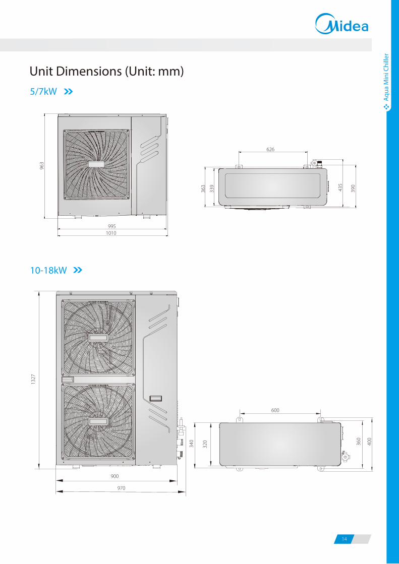
Unit Dimensions (Unit: mm)5/7kW
10-18kW
1327
900
970
963
1010995
626
435
339
363
390
Aqu
a M
ini C
hille
r
Aqu
a M
ini C
hille
r
13 14
600
340
320 40
0
360
208-230V/1Ph/60Hz
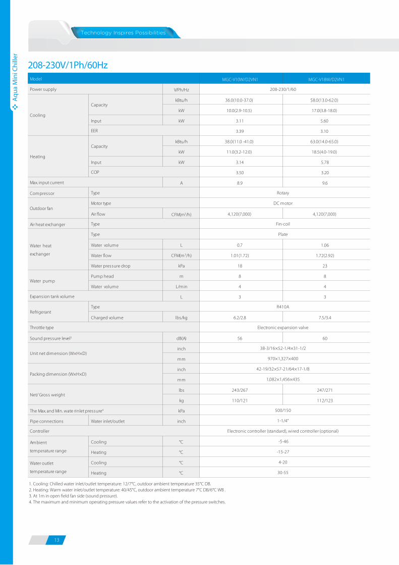
1. Cooling: Chilled water inlet/outlet temperature: 12/7°C, outdoor ambient temperature 35°C DB. 2. Heating: Warm water inlet/outlet temperature: 40/45°C, outdoor ambient temperature 7°C DB/6°C WB .3. At 1m in open field fan side (sound pressure).4. The maximum and minimum operating pressure values refer to the activation of the pressure switches.
MGC-V10W/D2VN1 MGC-V18W/D2VN1
V/Ph/Hz
kBtu/h 36.0(10.0-37.0) 58.0(13.0-62.0)
kW 10.0(2.9-10.5) 17.0(3.8-18.0)
Input kW 3.11 5.60
3.39 3.10
kBtu/h 38.0(11.0 -41.0) 63.0(14.0-65.0)
kW 11.0(3.2-12.0) 18.5(4.0-19.0)
Input kW 3.14 5.78
3.50 3.20
A 8.9 9.6
Compressor
Air flow CFM(m3/h) 4,120(7,000) 4,120(7,000)
Air heat exchanger
Water volume L 0.7 1.06
Water flow CFM(m3/h) 1.01(1.72) 1.72(2.92)
Water pressure drop kPa 18 23
Pump head m 8 8
Water volume L/min 4 4
L 3 3
Charged volume lbs/kg 6.2/2.8 7.5/3.4
dB(A) 56 60
inch
mm
inch
mm
lbs 243/267 247/271
kg 110/121 112/123
kPa
Pipe connections Water inlet/outlet inch
Cooling °C
Heating °C
Cooling °C
Heating °C
Model
Power supply
Capacity
Capacity
Electronic controller (standard), wired controller (optional)
Throttle type Electronic expansion valve
Sound pressure level3
RefrigerantType
Cooling
Heating
EER
COP
Type
Water heat
exchanger
Ambient
temperature range
Unit net dimension (W×H×D)
Packing dimension (W×H×D)
Net/ Gross weight
The Max. and Min. wate rinlet pressure4
Controller
Water outlet
temperature range
Type
Water pump
Expansion tank volume
Max. input current
Type
Outdoor fanMotor type
-5-46
-15-27
4-20
30-55
38-3/16×52-1/4×31-1/2
970×1,327×400
42-19/32×57-21/64×17-1/8
1,082×1,456×435
1-1/4“
500/150
208-230/1/60
R410A
Rotary
DC motor
Plate
Fin-coil
Unit Dimensions (Unit: mm)5/7kW
10-18kW
1327
900
970
963
1010995
626
435
339
363
390
Aqu
a M
ini C
hille
r
Aqu
a M
ini C
hille
r
13 14
600
340
320 40
0
360
208-230V/1Ph/60Hz
1. Cooling: Chilled water inlet/outlet temperature: 12/7°C, outdoor ambient temperature 35°C DB. 2. Heating: Warm water inlet/outlet temperature: 40/45°C, outdoor ambient temperature 7°C DB/6°C WB .3. At 1m in open field fan side (sound pressure).4. The maximum and minimum operating pressure values refer to the activation of the pressure switches.
MGC-V10W/D2VN1 MGC-V18W/D2VN1
V/Ph/Hz
kBtu/h 36.0(10.0-37.0) 58.0(13.0-62.0)
kW 10.0(2.9-10.5) 17.0(3.8-18.0)
Input kW 3.11 5.60
3.39 3.10
kBtu/h 38.0(11.0 -41.0) 63.0(14.0-65.0)
kW 11.0(3.2-12.0) 18.5(4.0-19.0)
Input kW 3.14 5.78
3.50 3.20
A 8.9 9.6
Compressor
Air flow CFM(m3/h) 4,120(7,000) 4,120(7,000)
Air heat exchanger
Water volume L 0.7 1.06
Water flow CFM(m3/h) 1.01(1.72) 1.72(2.92)
Water pressure drop kPa 18 23
Pump head m 8 8
Water volume L/min 4 4
L 3 3
Charged volume lbs/kg 6.2/2.8 7.5/3.4
dB(A) 56 60
inch
mm
inch
mm
lbs 243/267 247/271
kg 110/121 112/123
kPa
Pipe connections Water inlet/outlet inch
Cooling °C
Heating °C
Cooling °C
Heating °C
Model
Power supply
Capacity
Capacity
Electronic controller (standard), wired controller (optional)
Throttle type Electronic expansion valve
Sound pressure level3
RefrigerantType
Cooling
Heating
EER
COP
Type
Water heat
exchanger
Ambient
temperature range
Unit net dimension (W×H×D)
Packing dimension (W×H×D)
Net/ Gross weight
The Max. and Min. wate rinlet pressure4
Controller
Water outlet
temperature range
Type
Water pump
Expansion tank volume
Max. input current
Type
Outdoor fanMotor type
-5-46
-15-27
4-20
30-55
38-3/16×52-1/4×31-1/2
970×1,327×400
42-19/32×57-21/64×17-1/8
1,082×1,456×435
1-1/4“
500/150
208-230/1/60
R410A
Rotary
DC motor
Plate
Fin-coil
15 16
Fan
Coil
Uni
ts
Fan
Coil
Uni
ts
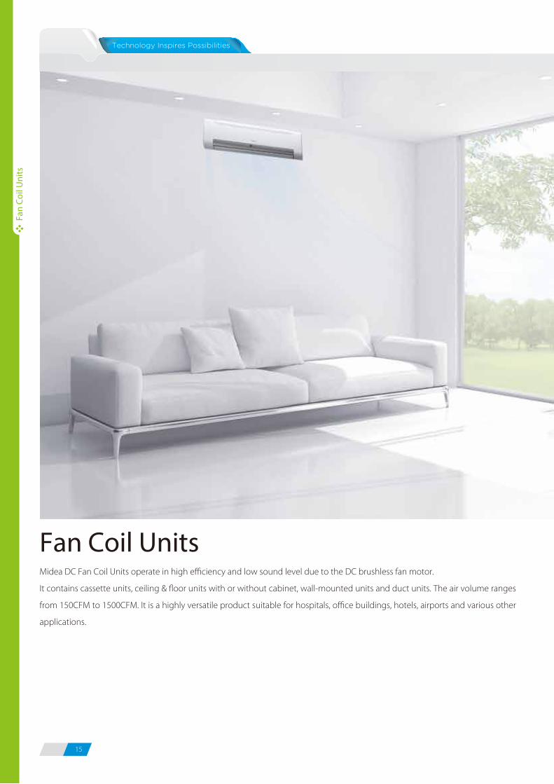
Midea DC Fan Coil Units operate in high efficiency and low sound level due to the DC brushless fan motor.
It contains cassette units, ceiling & floor units with or without cabinet, wall-mounted units and duct units. The air volume ranges
from 150CFM to 1500CFM. It is a highly versatile product suitable for hospitals, office buildings, hotels, airports and various other
applications.
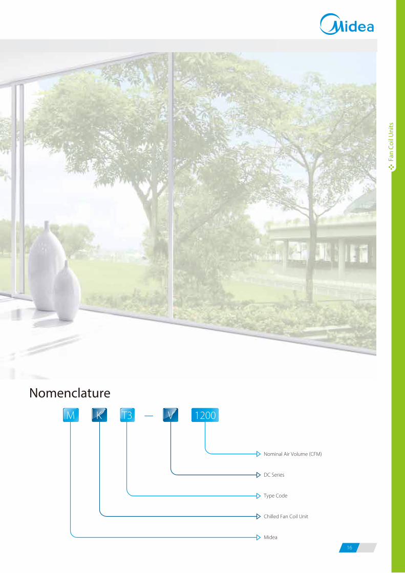
Fan Coil Units-T3
Type Code
M
Midea
V
DC Series
1200
Nominal Air Volume (CFM)
K
Chilled Fan Coil Unit
Nomenclature
15 16
Fan
Coil
Uni
ts
Fan
Coil
Uni
ts
Midea DC Fan Coil Units operate in high efficiency and low sound level due to the DC brushless fan motor.
It contains cassette units, ceiling & floor units with or without cabinet, wall-mounted units and duct units. The air volume ranges
from 150CFM to 1500CFM. It is a highly versatile product suitable for hospitals, office buildings, hotels, airports and various other
applications.
Fan Coil Units-T3
Type Code
M
Midea
V
DC Series
1200
Nominal Air Volume (CFM)
K
Chilled Fan Coil Unit
Nomenclature
17 18
Fan
Coil
Uni
tsFa
n Co
il U
nits
Fan
Coil
Uni
ts
Advantage of Fan Coil Units withDC Brushless Fan Motor
Energy E�ciency, Comply with CE Regulation
Quiet Operation
Constant Level of Air Temperature and Humidity
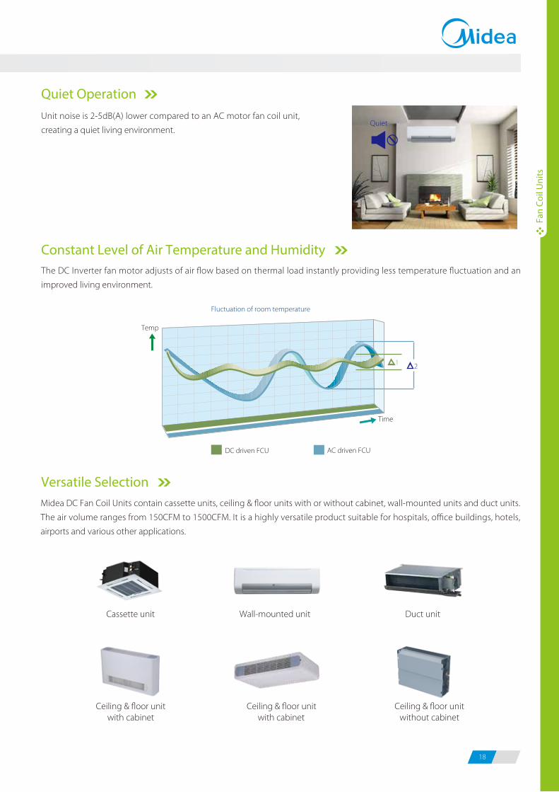
Versatile Selection Midea DC Fan Coil Units contain cassette units, ceiling & floor units with or without cabinet, wall-mounted units and duct units.
The air volume ranges from 150CFM to 1500CFM. It is a highly versatile product suitable for hospitals, office buildings, hotels,
airports and various other applications.
Duct unit
Ceiling & floor unitwithout cabinet
Cassette unit
Ceiling & floor unitwith cabinet
Ceiling & floor unitwith cabinet
Wall-mounted unit
Fluctuation of room temperature
Temp
DC driven FCU AC driven FCU
Time
The DC Inverter fan motor adjusts of air flow based on thermal load instantly providing less temperature fluctuation and an
improved living environment.
Unit noise is 2-5dB(A) lower compared to an AC motor fan coil unit,
creating a quiet living environment. Quiet
DC and AC motor’s power contrast
Power input: W
200
1200 Air Flow: CFM
DC motor
AC motor
1000800600500400300200
150
100
50
0
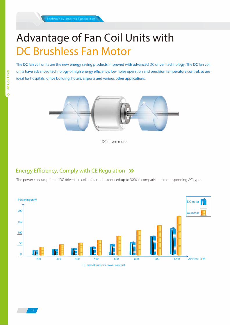
The power consumption of DC driven fan coil units can be reduced up to 30% in comparison to corresponding AC type.
The DC fan coil units are the new energy saving products improved with advanced DC driven technology. The DC fan coil
units have advanced technology of high energy e�ciency, low noise operation and precision temperature control, so are
ideal for hospitals, o�ce building, hotels, airports and various other applications.
DC driven motor
17 18
Fan
Coil
Uni
tsFa
n Co
il U
nits
Fan
Coil
Uni
ts
Advantage of Fan Coil Units withDC Brushless Fan Motor
Energy E�ciency, Comply with CE Regulation
Quiet Operation
Constant Level of Air Temperature and Humidity
Versatile Selection Midea DC Fan Coil Units contain cassette units, ceiling & floor units with or without cabinet, wall-mounted units and duct units.
The air volume ranges from 150CFM to 1500CFM. It is a highly versatile product suitable for hospitals, office buildings, hotels,
airports and various other applications.
Duct unit
Ceiling & floor unitwithout cabinet
Cassette unit
Ceiling & floor unitwith cabinet
Ceiling & floor unitwith cabinet
Wall-mounted unit
Fluctuation of room temperature
Temp
DC driven FCU AC driven FCU
Time
The DC Inverter fan motor adjusts of air flow based on thermal load instantly providing less temperature fluctuation and an
improved living environment.
Unit noise is 2-5dB(A) lower compared to an AC motor fan coil unit,
creating a quiet living environment. Quiet
DC and AC motor’s power contrast
Power input: W
200
1200 Air Flow: CFM
DC motor
AC motor
1000800600500400300200
150
100
50
0
The power consumption of DC driven fan coil units can be reduced up to 30% in comparison to corresponding AC type.
The DC fan coil units are the new energy saving products improved with advanced DC driven technology. The DC fan coil
units have advanced technology of high energy e�ciency, low noise operation and precision temperature control, so are
ideal for hospitals, o�ce building, hotels, airports and various other applications.
DC driven motor
19 20
Fan
Coil
Uni
ts
Fan
Coil
Uni
ts
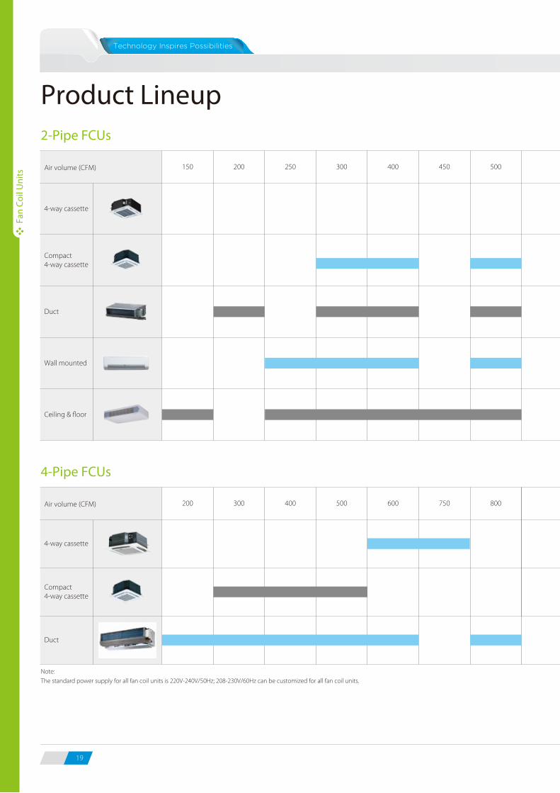
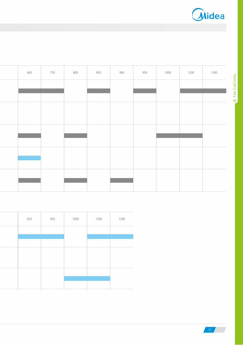
Product Lineup2-Pipe FCUs
Air volume (CFM) 150 200 250 300 400 450 500 600 750 800 850 900 950 1000 1200 1500
Compact 4-way cassette
Duct
4-Pipe FCUs
Air volume (CFM) 200 400 500 600 750 850 950 1200 1500
Compact 4-way cassette
Note:
The standard power supply for all fan coil units is 220V-240V/50Hz; 208-230V/60Hz can be customized for all fan coil units.
Ceiling & floor
Wall mounted
4-way cassette
4-way cassette
Duct
300 800 1000
19 20
Fan
Coil
Uni
ts
Fan
Coil
Uni
ts
Product Lineup2-Pipe FCUs
Air volume (CFM) 150 200 250 300 400 450 500 600 750 800 850 900 950 1000 1200 1500
Compact 4-way cassette
Duct
4-Pipe FCUs
Air volume (CFM) 200 400 500 600 750 850 950 1200 1500
Compact 4-way cassette
Note:
The standard power supply for all fan coil units is 220V-240V/50Hz; 208-230V/60Hz can be customized for all fan coil units.
Ceiling & floor
Wall mounted
4-way cassette
4-way cassette
Duct
300 800 1000
21 22
Fan
Coil
Uni
ts
Fan
Coil
Uni
ts
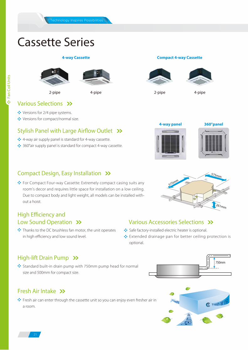
Cassette SeriesCompact 4-way Cassette
2-pipe 4-pipe
4-way Cassette
2-pipe 4-pipe
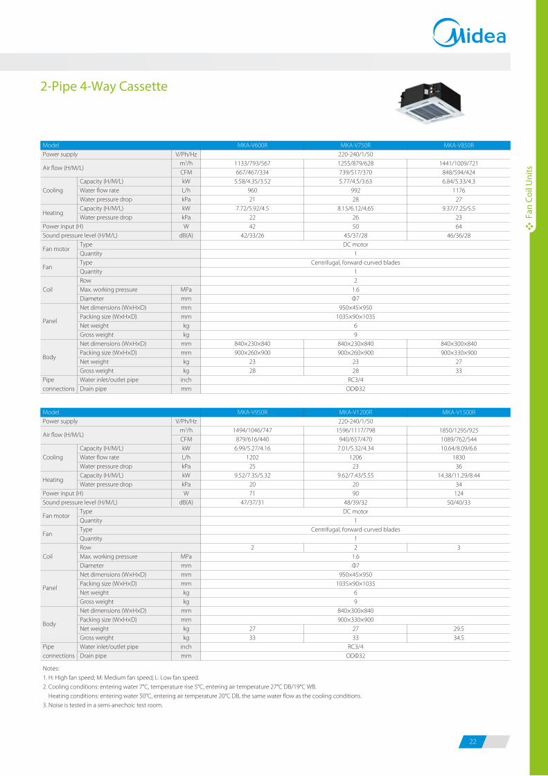
2-Pipe 4-Way Cassette
ModelPower supply
Cooling
Power input (H)Sound pressure level (H/M/L)
Coil
Pipe connections
Capacity (H/M/L)Water flow rateWater pressure dropCapacity (H/M/L)Water pressure drop
TypeQuantityTypeQuantityRowMax. working pressureDiameterNet dimensions (W×H×D)Packing size (W×H×D)Net weightGross weightNet dimensions (W×H×D)Packing size (W×H×D)Net weight Gross weight Water inlet/outlet pipeDrain pipe
V/Ph/Hzm3/hCFMkWL/hkPakWkPaW
dB(A)
MPammmmmmkgkg
mmmmkgkg
inchmm
MKA-V600R
1133/793/567667/467/334
5.58/4.35/3.5296021
7.72/5.92/4.52242
42/33/26
840×230×840900×260×900
2328
MKA-V750R220-240/1/501255/879/628739/517/3705.77/4.5/3.63
99228
8.15/6.12/4.652650
45/37/28DC motor
1Centrifugal, forward-curved blades
12
1.6Φ7
950×45×9501035×90×1035
69
840×230×840900×260×900
2328
RC3/4ODΦ32
MKA-V850R
1441/1009/721848/594/4246.84/5.33/4.3
117627
9.37/7.25/5.52364
46/36/28
840×300×840900×330×900
2733
Air flow (H/M/L)
Heating
Fan motor
Fan
Panel
Body
ModelPower supply
Cooling
Power input (H)Sound pressure level (H/M/L)
Coil
Pipe connections
Capacity (H/M/L)Water flow rateWater pressure dropCapacity (H/M/L)Water pressure drop
TypeQuantityTypeQuantityRowMax. working pressureDiameterNet dimensions (W×H×D)Packing size (W×H×D)Net weightGross weightNet dimensions (W×H×D)Packing size (W×H×D)Net weight Gross weight Water inlet/outlet pipeDrain pipe
V/Ph/Hzm3/hCFMkWL/hkPakWkPaW
dB(A)
MPammmmmmkgkg
mmmmkgkg
inchmm
MKA-V950R
1494/1046/747879/616/440
6.99/5.27/4.161202
259.52/7.35/5.32
2071
47/37/31
2
2733
MKA-V1200R220-240/1/50
1596/1117/798940/657/470
7.01/5.32/4.341206
239.62/7.43/5.55
2090
48/39/32DC motor
1Centrifugal, forward-curved blades
12
1.6Φ7
950×45×9501035×90×1035
69
840×300×840900×330×900
2733
RC3/4ODΦ32
MKA-V1500R
1850/1295/9251089/762/54410.64/8.09/6.6
183036
14.38/11.29/8.4434
12450/40/33
3
29.534.5
Notes:
1. H: High fan speed; M: Medium fan speed; L: Low fan speed.
2. Cooling conditions: entering water 7°C, temperature rise 5°C, entering air temperature 27°C DB/19°C WB.
Heating conditions: entering water 50°C, entering air temperature 20°C DB, the same water flow as the cooling conditions.
3. Noise is tested in a semi-anechoic test room.
Various SelectionsVersions for 2/4 pipe systems.
Versions for compact/normal size.
4-way air supply panel is standard for 4-way cassette.
360°air supply panel is standard for compact 4-way cassette.
Stylish Panel with Large Air�ow Outlet4-way panel 360°panel
For Compact Four-way Cassette: Extremely compact casing suits any
room's decor and requires little space for installation on a low ceiling.
Due to compact body and light weight, all models can be installed with-
out a hoist.
Standard built-in drain pump with 750mm pump head for normal
size and 500mm for compact size.
575mm
261mm
575mm
Compact Design, Easy Installation
High-lift Drain Pump
Fresh air can enter through the cassette unit so you can enjoy even fresher air in
a room.
Fresh Air Intake
750mm
Safe factory-installed electric heater is optional.
Extended drainage pan for better ceiling protection is
optional.
Various Accessories SelectionsThanks to the DC brushless fan motor, the unit operates
in high efficiency and low sound level.
High E�ciency and Low Sound Operation
Air flow (H/M/L)
Heating
Fan motor
Fan
Panel
Body
21 22
Fan
Coil
Uni
ts
Fan
Coil
Uni
ts
Cassette SeriesCompact 4-way Cassette
2-pipe 4-pipe
4-way Cassette
2-pipe 4-pipe
2-Pipe 4-Way Cassette
ModelPower supply
Cooling
Power input (H)Sound pressure level (H/M/L)
Coil
Pipe connections
Capacity (H/M/L)Water flow rateWater pressure dropCapacity (H/M/L)Water pressure drop
TypeQuantityTypeQuantityRowMax. working pressureDiameterNet dimensions (W×H×D)Packing size (W×H×D)Net weightGross weightNet dimensions (W×H×D)Packing size (W×H×D)Net weight Gross weight Water inlet/outlet pipeDrain pipe
V/Ph/Hzm3/hCFMkWL/hkPakWkPaW
dB(A)
MPammmmmmkgkg
mmmmkgkg
inchmm
MKA-V600R
1133/793/567667/467/334
5.58/4.35/3.5296021
7.72/5.92/4.52242
42/33/26
840×230×840900×260×900
2328
MKA-V750R220-240/1/501255/879/628739/517/3705.77/4.5/3.63
99228
8.15/6.12/4.652650
45/37/28DC motor
1Centrifugal, forward-curved blades
12
1.6Φ7
950×45×9501035×90×1035
69
840×230×840900×260×900
2328
RC3/4ODΦ32
MKA-V850R
1441/1009/721848/594/4246.84/5.33/4.3
117627
9.37/7.25/5.52364
46/36/28
840×300×840900×330×900
2733
Air flow (H/M/L)
Heating
Fan motor
Fan
Panel
Body
ModelPower supply
Cooling
Power input (H)Sound pressure level (H/M/L)
Coil
Pipe connections
Capacity (H/M/L)Water flow rateWater pressure dropCapacity (H/M/L)Water pressure drop
TypeQuantityTypeQuantityRowMax. working pressureDiameterNet dimensions (W×H×D)Packing size (W×H×D)Net weightGross weightNet dimensions (W×H×D)Packing size (W×H×D)Net weight Gross weight Water inlet/outlet pipeDrain pipe
V/Ph/Hzm3/hCFMkWL/hkPakWkPaW
dB(A)
MPammmmmmkgkg
mmmmkgkg
inchmm
MKA-V950R
1494/1046/747879/616/440
6.99/5.27/4.161202
259.52/7.35/5.32
2071
47/37/31
2
2733
MKA-V1200R220-240/1/50
1596/1117/798940/657/470
7.01/5.32/4.341206
239.62/7.43/5.55
2090
48/39/32DC motor
1Centrifugal, forward-curved blades
12
1.6Φ7
950×45×9501035×90×1035
69
840×300×840900×330×900
2733
RC3/4ODΦ32
MKA-V1500R
1850/1295/9251089/762/54410.64/8.09/6.6
183036
14.38/11.29/8.4434
12450/40/33
3
29.534.5
Notes:
1. H: High fan speed; M: Medium fan speed; L: Low fan speed.
2. Cooling conditions: entering water 7°C, temperature rise 5°C, entering air temperature 27°C DB/19°C WB.
Heating conditions: entering water 50°C, entering air temperature 20°C DB, the same water flow as the cooling conditions.
3. Noise is tested in a semi-anechoic test room.
Various SelectionsVersions for 2/4 pipe systems.
Versions for compact/normal size.
4-way air supply panel is standard for 4-way cassette.
360°air supply panel is standard for compact 4-way cassette.
Stylish Panel with Large Air�ow Outlet4-way panel 360°panel
For Compact Four-way Cassette: Extremely compact casing suits any
room's decor and requires little space for installation on a low ceiling.
Due to compact body and light weight, all models can be installed with-
out a hoist.
Standard built-in drain pump with 750mm pump head for normal
size and 500mm for compact size.
575mm
261mm
575mm
Compact Design, Easy Installation
High-lift Drain Pump
Fresh air can enter through the cassette unit so you can enjoy even fresher air in
a room.
Fresh Air Intake
750mm
Safe factory-installed electric heater is optional.
Extended drainage pan for better ceiling protection is
optional.
Various Accessories SelectionsThanks to the DC brushless fan motor, the unit operates
in high efficiency and low sound level.
High E�ciency and Low Sound Operation
Air flow (H/M/L)
Heating
Fan motor
Fan
Panel
Body
Fan
Coil
Uni
ts
Fan
Coil
Uni
ts
23 24
4-Pipe 4-Way Cassette 2-Pipe Compact 4-Way Cassette
4-Pipe Compact 4-Way Cassette
ModelPower supply
Cooling
Power input (H)Sound pressure level (H/M/L)
Coil
Pipe connections
Capacity (H/M/L)Water flow rateWater pressure dropCapacity (H/M/L)Water pressure drop
TypeQuantityTypeQuantityRowMax. working pressureDiameterNet dimensions (W×H×D)Packing size (W×H×D)Net weightGross weightNet dimensions (W×H×D)Packing size (W×H×D)Net weightGross weight Water inlet/outlet pipeDrain pipe
V/Ph/Hzm3/hCFMkWL/hkPakWkPaW
dB(A)
MPammmmmmkgkg
mmmmkgkg
inchmm
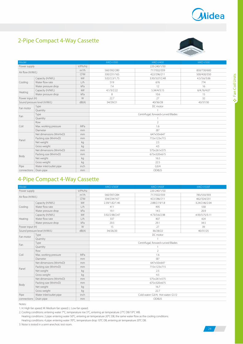
MKD-V300
560/392/280330/231/1653.02/2.3/1.75
5197.4
4.1/3/2.228
22.734/29/21
MKD-V400220-240/1/50717/502/359422/296/211
3.93/3.07/2.4867612
5.34/4/3.1510.627
40/36/28DC motor
1Centrifugal, forward-curved Blades
12
1.6Φ7
647×50×647715×123×715
2.54.5
575×261×575675×320×675
16.522.5G3/4
ODΦ25
MKD-V500
850/730/600500/430/3504.5/3.6/3.06
774 16
6/4.76/4.071532
43/37/30
ModelPower supply
Cooling
Heating
Power input (H)Sound pressure level (H/M/L)
Coil
Pipe connections
Capacity (H/M/L)Water flow rateWater pressure dropCapacity (H/M/L)Water flow rateWater pressure drop
TypeQuantityTypeQuantityRowMax. working pressureDiameterNet dimensions (W×H×D)Packing size (W×H×D)Net weightGross weightNet dimensions (W×H×D)Packing size (W×H×D)Net weight Gross weightWater inlet/outlet pipeDrain pipe
V/Ph/Hzm3/hCFMkWL/hkPakWL/hkPaW
dB(A)
MPammmmmmkgkg
mmmmkgkg
inchmm
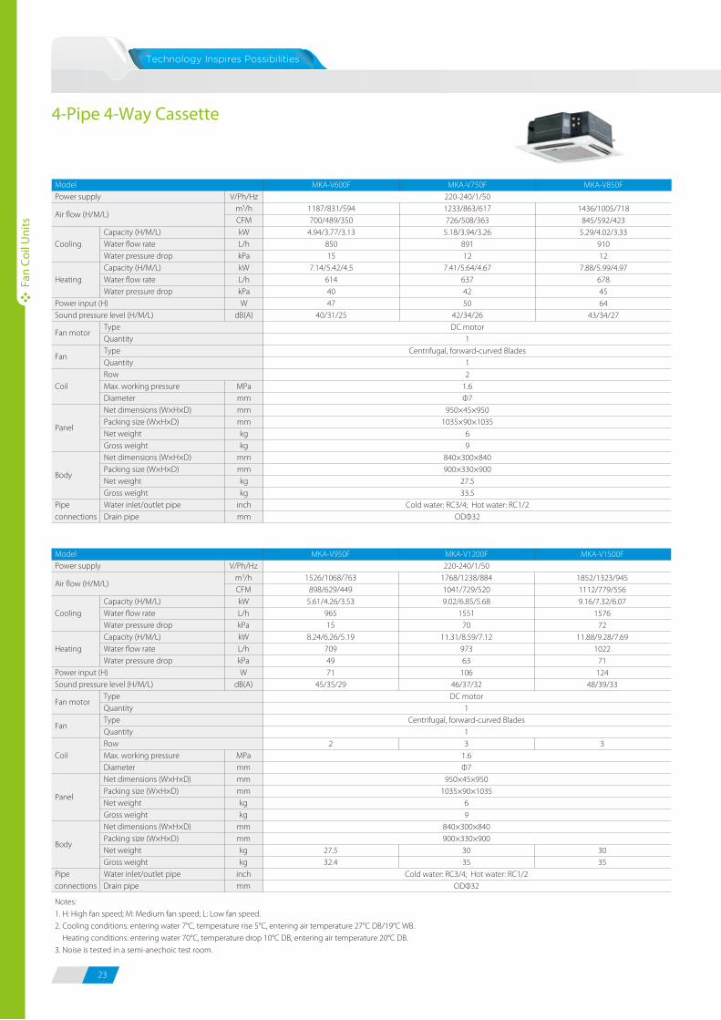
MKA-V600F
1187/831/594700/489/350
4.94/3.77/3.1385015
7.14/5.42/4.56144047
40/31/25
MKA-V750F220-240/1/501233/863/617726/508/363
5.18/3.94/3.2689112
7.41/5.64/4.676374250
42/34/26DC motor
1Centrifugal, forward-curved Blades
12
1.6Φ7
950×45×9501035×90×1035
69
840×300×840900×330×900
27.533.5
Cold water: RC3/4; Hot water: RC1/2ODΦ32
MKA-V850F
1436/1005/718845/592/423
5.29/4.02/3.3391012
7.88/5.99/4.976784564
43/34/27
ModelPower supply
Cooling
Heating
Power input (H)Sound pressure level (H/M/L)
Coil
Pipe connections
Capacity (H/M/L)Water flow rateWater pressure dropCapacity (H/M/L)Water flow rateWater pressure drop
TypeQuantityTypeQuantityRowMax. working pressureDiameterNet dimensions (W×H×D)Packing size (W×H×D)Net weightGross weightNet dimensions (W×H×D)Packing size (W×H×D)Net weight Gross weightWater inlet/outlet pipeDrain pipe
V/Ph/Hzm3/hCFMkWL/hkPakWL/hkPaW
dB(A)
MPammmmmmkgkg
mmmmkgkg
inchmm
MKA-V950F
1526/1068/763898/629/449
5.61/4.26/3.5396515
8.24/6.26/5.197094971
45/35/29
2
27.532.4
MKA-V1200F220-240/1/50
1768/1238/8841041/729/5209.02/6.85/5.68
155170
11.31/8.59/7.1297363
10646/37/32DC motor
1Centrifugal, forward-curved Blades
13
1.6Φ7
950×45×9501035×90×1035
69
840×300×840900×330×900
3035
Cold water: RC3/4; Hot water: RC1/2ODΦ32
MKA-V1500F
1852/1323/9451112/779/5569.16/7.32/6.07
157672
11.88/9.28/7.691022
71124
48/39/33
3
3035
ModelPower supply
Cooling
Heating
Power input (H)Sound pressure level (H/M/L)
Coil
Pipe connections
Capacity (H/M/L)Water flow rateWater pressure dropCapacity (H/M/L)Water flow rateWater pressure drop
TypeQuantityTypeQuantityRowMax. working pressureDiameterNet dimensions (W×H×D)Packing size (W×H×D)Net weightGross weightNet dimensions (W×H×D)Packing size (W×H×D)Net weight Gross weightWater inlet/outlet pipeDrain pipe
V/Ph/Hzm3/hCFMkWL/hkPakWL/hkPaW
dB(A)
MPammmmmmkgkg
mmmmkgkg
inchmm
MKD-V300F
560/397/284334/234/167
2.39/1.82/1.4641119.1
3.92/2.98/2.4733720.515
34/26/20
MKD-V400F220-240/1/50717/502/359422/286/2112.88/2.19/1.8
49514.5
4.73/3.6/2.9840729.127
36/28/22DC motor
1Centrifugal, forward-curved Blades
12
1.6Φ7
647×50×647715×123×715
2.54.5
575×261×575675×320×675
16.722.7
Cold water: G3/4; Hot water: G1/2ODΦ25
MKD-V500F
785/550/393462/324/231
3.24/2.46/2.0455820.9
4.93/3.75/3.1142434.539
40/31/25
Notes:
1. H: High fan speed; M: Medium fan speed; L: Low fan speed.
2. Cooling conditions: entering water 7°C, temperature rise 5°C, entering air temperature 27°C DB/19°C WB.
Heating conditions: entering water 70°C, temperature drop 10°C DB, entering air temperature 20°C DB.
3. Noise is tested in a semi-anechoic test room.
Notes:
1. H: High fan speed; M: Medium fan speed; L: Low fan speed.
2. Cooling conditions: entering water 7°C, temperature rise 5°C, entering air temperature 27°C DB/19°C WB.
Heating conditions: 2 pipe: entering water 50°C, entering air temperature 20°C DB, the same water flow as the cooling conditions.
Heating conditions: 4 pipe: entering water 70°C, temperature drop 10°C DB, entering air temperature 20°C DB.
3. Noise is tested in a semi-anechoic test room.
Air flow (H/M/L)
Fan motor
Fan
Panel
Body
Air flow (H/M/L)
Fan motor
Fan
Panel
Body
Air flow (H/M/L)
Heating
Fan motor
Fan
Panel
Body
Air flow (H/M/L)
Fan motor
Fan
Panel
Body
Fan
Coil
Uni
ts
Fan
Coil
Uni
ts
23 24
4-Pipe 4-Way Cassette 2-Pipe Compact 4-Way Cassette
4-Pipe Compact 4-Way Cassette
ModelPower supply
Cooling
Power input (H)Sound pressure level (H/M/L)
Coil
Pipe connections
Capacity (H/M/L)Water flow rateWater pressure dropCapacity (H/M/L)Water pressure drop
TypeQuantityTypeQuantityRowMax. working pressureDiameterNet dimensions (W×H×D)Packing size (W×H×D)Net weightGross weightNet dimensions (W×H×D)Packing size (W×H×D)Net weightGross weight Water inlet/outlet pipeDrain pipe
V/Ph/Hzm3/hCFMkWL/hkPakWkPaW
dB(A)
MPammmmmmkgkg
mmmmkgkg
inchmm
MKD-V300
560/392/280330/231/1653.02/2.3/1.75
5197.4
4.1/3/2.228
22.734/29/21
MKD-V400220-240/1/50717/502/359422/296/211
3.93/3.07/2.4867612
5.34/4/3.1510.627
40/36/28DC motor
1Centrifugal, forward-curved Blades
12
1.6Φ7
647×50×647715×123×715
2.54.5
575×261×575675×320×675
16.522.5G3/4
ODΦ25
MKD-V500
850/730/600500/430/3504.5/3.6/3.06
774 16
6/4.76/4.071532
43/37/30
ModelPower supply
Cooling
Heating
Power input (H)Sound pressure level (H/M/L)
Coil
Pipe connections
Capacity (H/M/L)Water flow rateWater pressure dropCapacity (H/M/L)Water flow rateWater pressure drop
TypeQuantityTypeQuantityRowMax. working pressureDiameterNet dimensions (W×H×D)Packing size (W×H×D)Net weightGross weightNet dimensions (W×H×D)Packing size (W×H×D)Net weight Gross weightWater inlet/outlet pipeDrain pipe
V/Ph/Hzm3/hCFMkWL/hkPakWL/hkPaW
dB(A)
MPammmmmmkgkg
mmmmkgkg
inchmm
MKA-V600F
1187/831/594700/489/350
4.94/3.77/3.1385015
7.14/5.42/4.56144047
40/31/25
MKA-V750F220-240/1/501233/863/617726/508/363
5.18/3.94/3.2689112
7.41/5.64/4.676374250
42/34/26DC motor
1Centrifugal, forward-curved Blades
12
1.6Φ7
950×45×9501035×90×1035
69
840×300×840900×330×900
27.533.5
Cold water: RC3/4; Hot water: RC1/2ODΦ32
MKA-V850F
1436/1005/718845/592/423
5.29/4.02/3.3391012
7.88/5.99/4.976784564
43/34/27
ModelPower supply
Cooling
Heating
Power input (H)Sound pressure level (H/M/L)
Coil
Pipe connections
Capacity (H/M/L)Water flow rateWater pressure dropCapacity (H/M/L)Water flow rateWater pressure drop
TypeQuantityTypeQuantityRowMax. working pressureDiameterNet dimensions (W×H×D)Packing size (W×H×D)Net weightGross weightNet dimensions (W×H×D)Packing size (W×H×D)Net weight Gross weightWater inlet/outlet pipeDrain pipe
V/Ph/Hzm3/hCFMkWL/hkPakWL/hkPaW
dB(A)
MPammmmmmkgkg
mmmmkgkg
inchmm
MKA-V950F
1526/1068/763898/629/449
5.61/4.26/3.5396515
8.24/6.26/5.197094971
45/35/29
2
27.532.4
MKA-V1200F220-240/1/50
1768/1238/8841041/729/5209.02/6.85/5.68
155170
11.31/8.59/7.1297363
10646/37/32DC motor
1Centrifugal, forward-curved Blades
13
1.6Φ7
950×45×9501035×90×1035
69
840×300×840900×330×900
3035
Cold water: RC3/4; Hot water: RC1/2ODΦ32
MKA-V1500F
1852/1323/9451112/779/5569.16/7.32/6.07
157672
11.88/9.28/7.691022
71124
48/39/33
3
3035
ModelPower supply
Cooling
Heating
Power input (H)Sound pressure level (H/M/L)
Coil
Pipe connections
Capacity (H/M/L)Water flow rateWater pressure dropCapacity (H/M/L)Water flow rateWater pressure drop
TypeQuantityTypeQuantityRowMax. working pressureDiameterNet dimensions (W×H×D)Packing size (W×H×D)Net weightGross weightNet dimensions (W×H×D)Packing size (W×H×D)Net weight Gross weightWater inlet/outlet pipeDrain pipe
V/Ph/Hzm3/hCFMkWL/hkPakWL/hkPaW
dB(A)
MPammmmmmkgkg
mmmmkgkg
inchmm
MKD-V300F
560/397/284334/234/167
2.39/1.82/1.4641119.1
3.92/2.98/2.4733720.515
34/26/20
MKD-V400F220-240/1/50717/502/359422/286/2112.88/2.19/1.8
49514.5
4.73/3.6/2.9840729.127
36/28/22DC motor
1Centrifugal, forward-curved Blades
12
1.6Φ7
647×50×647715×123×715
2.54.5
575×261×575675×320×675
16.722.7
Cold water: G3/4; Hot water: G1/2ODΦ25
MKD-V500F
785/550/393462/324/231
3.24/2.46/2.0455820.9
4.93/3.75/3.1142434.539
40/31/25
Notes:
1. H: High fan speed; M: Medium fan speed; L: Low fan speed.
2. Cooling conditions: entering water 7°C, temperature rise 5°C, entering air temperature 27°C DB/19°C WB.
Heating conditions: entering water 70°C, temperature drop 10°C DB, entering air temperature 20°C DB.
3. Noise is tested in a semi-anechoic test room.
Notes:
1. H: High fan speed; M: Medium fan speed; L: Low fan speed.
2. Cooling conditions: entering water 7°C, temperature rise 5°C, entering air temperature 27°C DB/19°C WB.
Heating conditions: 2 pipe: entering water 50°C, entering air temperature 20°C DB, the same water flow as the cooling conditions.
Heating conditions: 4 pipe: entering water 70°C, temperature drop 10°C DB, entering air temperature 20°C DB.
3. Noise is tested in a semi-anechoic test room.
Air flow (H/M/L)
Fan motor
Fan
Panel
Body
Air flow (H/M/L)
Fan motor
Fan
Panel
Body
Air flow (H/M/L)
Heating
Fan motor
Fan
Panel
Body
Air flow (H/M/L)
Fan motor
Fan
Panel
Body
25 26
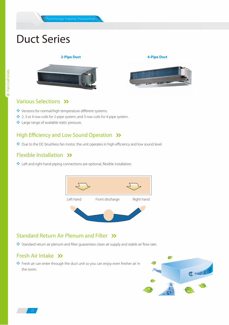
Duct Series
Various Selections
Versions for normal/high temperature different systems.
2, 3 or 4 row coils for 2-pipe system, and 3 row coils for 4-pipe system.
Large range of available static pressure.
Standard Return Air Plenum and Filter
Fresh air can enter through the duct unit so you can enjoy even fresher air in
the room.
Fresh Air Intake
Left and right hand piping connections are optional, flexible installation.
Flexible Installation
Standard return air plenum and filter guarantees clean air supply and stable air flow rate.
2-Pipe Duct 4-Pipe Duct
Due to the DC brushless fan motor, the unit operates in high efficiency and low sound level.
High E�ciency and Low Sound Operation
220-240/1/50
12Pa (default), 30/50Pa can be set through dial switch on PCB
DC motor
1
Centrifugal, forward-curved Blades
2
1.6
Φ9.52
RC3/4
R3/4
2-Pipe 2-Row Duct
Notes:1. H: High fan speed; M: Medium fan speed; L: Low fan speed.2. Air flow rate at 0Pa ESP.3. Cooling conditions: entering water 7°C, temperature rise 5°C, entering air temperature 27°C DB/19°C WB. Heating conditions: entering water 50°C, entering air temperature 20°C DB, the same water flow as the cooling conditions.4. Noise is tested in a semi-anechoic test room.
Model
Power supply
Standard external static pressure
Cooling
Power input (H)
Coil
Net dimensions (W×H×D)
Packing size (W×H×D)
Net weight
Gross weight
Water inlet/outlet pipe
Drain pipe
Capacity (H/M/L)
Water flow rate
Water pressure drop
Capacity (H/M/L)
Water pressure drop
12Pa (H/M/L)
30Pa (H/M/L)
50Pa (H/M/L)
Type
Quantity
Type
Quantity
Row
Max. working pressure
Diameter
V/Ph/Hz
m3/h
CFM
Pa
kW
L/h
kPa
kW
kPa
W
dB(A)
dB(A)
dB(A)
MPa
mm
mm
mm
kg
kg
inch
mm
MKT2-V200
340/255/170
200/150/100
2/1.74/1.52
344
6.1
3.2/2.75/2.37
5.6
20
35/32/25
40/36/29
43/39/31
1
741×241×522
790×260×550
16.5
19
MKT2-V300
510/385/255
300/225/150
2.7/2.31/2.03
464
11.4
4.3/3.74/3.23
9.7
26
36/33/26
41/37/30
44/40/32
2
841×241×522
890×260×550
18.5
21.4
MKT2-V400
680/510/340
400/300/200
3.6/3.11/2.66
619
20.4
5.4/4.64/4.05
17.7
38
37/34/27
42/38/31
45/41/33
2
941×241×522
990×260×550
20
23.2
MKT2-V500
850/640/425
500/375/250
4.4/3.74/3.25
757
20.1
6.8/5.78/5.07
18.9
48
38/35/28
43/39/32
46/42/34
2
941×241×522
990×260×550
20
23.2
Model
Power supply
Standard external static pressure
Cooling
Power input (H)
Coil
Net dimensions (W×H×D)
Packing size (W×H×D)
Net weight
Gross weight
Water inlet/outlet pipe
Drain pipe
Capacity (H/M/L)
Water flow rate
Water pressure drop
Capacity (H/M/L)
Water pressure drop
12Pa (H/M/L)
30Pa (H/M/L)
50Pa (H/M/L)
Type
Quantity
Type
Quantity
Row
Max. working pressure
Diameter
V/Ph/Hz
m3/h
CFM
Pa
kW
L/h
kPa
kW
kPa
W
dB(A)
dB(A)
dB(A)
MPa
mm
mm
mm
kg
kg
inch
mm
MKT2-V600
1020/765/510
600/450/300
5.5/4.58/4.09
946
13.9
8.1/6.77/5.92
11.6
54
39/36/29
44/40/33
47/43/35
1
2
1161×241×522
1210×260×550
22.2
26
MKT2-V800
1360/1020/680
800/600/400
7.5/6.33/5.68
1290
12.4
11/9.48/8.25
10.6
74
40/37/30
45/41/34
48/44/36
2
4
1461×241×522
1510×260×550
31.4
35.8
MKT2-V1000
1700/1275/850
1000/750/500
8.9/7.61/6.41
1531
21.4
13.5/11.72/10.03
18.4
99
42/39/32
46/42/34
50/45/37
2
4
1566×241×522
1615×260×550
32.5
37.2
MKT2-V1200
2040/1530/1020
1200/900/600
10.8/9.13/7.93
1858
28.1
16.5/14.05/12.24
22.8
135
44/40/33
47/43/34
50/46/38
2
4
1856×241×522
1905×260×550
37.5
42.8
220-240/1/50
12Pa (default), 30/50Pa can be set through dial switch on PCB
DC motor
Centrifugal, forward-curved Blades
2
1.6
Φ9.52
RC3/4
R3/4
Fan
Coil
Uni
ts
Fan
Coil
Uni
ts
Left hand Right handFront discharge
Air flow (H/M/L)
Heating
Sound pressure level
Fan motor
Fan
Air flow (H/M/L)
Heating
Sound pressure level
Fan motor
Fan

25 26
Duct Series
Various Selections
Versions for normal/high temperature different systems.
2, 3 or 4 row coils for 2-pipe system, and 3 row coils for 4-pipe system.
Large range of available static pressure.
Standard Return Air Plenum and Filter
Fresh air can enter through the duct unit so you can enjoy even fresher air in
the room.
Fresh Air Intake
Left and right hand piping connections are optional, flexible installation.
Flexible Installation
Standard return air plenum and filter guarantees clean air supply and stable air flow rate.
2-Pipe Duct 4-Pipe Duct
Due to the DC brushless fan motor, the unit operates in high efficiency and low sound level.
High E�ciency and Low Sound Operation
220-240/1/50
12Pa (default), 30/50Pa can be set through dial switch on PCB
DC motor
1
Centrifugal, forward-curved Blades
2
1.6
Φ9.52
RC3/4
R3/4
2-Pipe 2-Row Duct
Notes:1. H: High fan speed; M: Medium fan speed; L: Low fan speed.2. Air flow rate at 0Pa ESP.3. Cooling conditions: entering water 7°C, temperature rise 5°C, entering air temperature 27°C DB/19°C WB. Heating conditions: entering water 50°C, entering air temperature 20°C DB, the same water flow as the cooling conditions.4. Noise is tested in a semi-anechoic test room.
Model
Power supply
Standard external static pressure
Cooling
Power input (H)
Coil
Net dimensions (W×H×D)
Packing size (W×H×D)
Net weight
Gross weight
Water inlet/outlet pipe
Drain pipe
Capacity (H/M/L)
Water flow rate
Water pressure drop
Capacity (H/M/L)
Water pressure drop
12Pa (H/M/L)
30Pa (H/M/L)
50Pa (H/M/L)
Type
Quantity
Type
Quantity
Row
Max. working pressure
Diameter
V/Ph/Hz
m3/h
CFM
Pa
kW
L/h
kPa
kW
kPa
W
dB(A)
dB(A)
dB(A)
MPa
mm
mm
mm
kg
kg
inch
mm
MKT2-V200
340/255/170
200/150/100
2/1.74/1.52
344
6.1
3.2/2.75/2.37
5.6
20
35/32/25
40/36/29
43/39/31
1
741×241×522
790×260×550
16.5
19
MKT2-V300
510/385/255
300/225/150
2.7/2.31/2.03
464
11.4
4.3/3.74/3.23
9.7
26
36/33/26
41/37/30
44/40/32
2
841×241×522
890×260×550
18.5
21.4
MKT2-V400
680/510/340
400/300/200
3.6/3.11/2.66
619
20.4
5.4/4.64/4.05
17.7
38
37/34/27
42/38/31
45/41/33
2
941×241×522
990×260×550
20
23.2
MKT2-V500
850/640/425
500/375/250
4.4/3.74/3.25
757
20.1
6.8/5.78/5.07
18.9
48
38/35/28
43/39/32
46/42/34
2
941×241×522
990×260×550
20
23.2
Model
Power supply
Standard external static pressure
Cooling
Power input (H)
Coil
Net dimensions (W×H×D)
Packing size (W×H×D)
Net weight
Gross weight
Water inlet/outlet pipe
Drain pipe
Capacity (H/M/L)
Water flow rate
Water pressure drop
Capacity (H/M/L)
Water pressure drop
12Pa (H/M/L)
30Pa (H/M/L)
50Pa (H/M/L)
Type
Quantity
Type
Quantity
Row
Max. working pressure
Diameter
V/Ph/Hz
m3/h
CFM
Pa
kW
L/h
kPa
kW
kPa
W
dB(A)
dB(A)
dB(A)
MPa
mm
mm
mm
kg
kg
inch
mm
MKT2-V600
1020/765/510
600/450/300
5.5/4.58/4.09
946
13.9
8.1/6.77/5.92
11.6
54
39/36/29
44/40/33
47/43/35
1
2
1161×241×522
1210×260×550
22.2
26
MKT2-V800
1360/1020/680
800/600/400
7.5/6.33/5.68
1290
12.4
11/9.48/8.25
10.6
74
40/37/30
45/41/34
48/44/36
2
4
1461×241×522
1510×260×550
31.4
35.8
MKT2-V1000
1700/1275/850
1000/750/500
8.9/7.61/6.41
1531
21.4
13.5/11.72/10.03
18.4
99
42/39/32
46/42/34
50/45/37
2
4
1566×241×522
1615×260×550
32.5
37.2
MKT2-V1200
2040/1530/1020
1200/900/600
10.8/9.13/7.93
1858
28.1
16.5/14.05/12.24
22.8
135
44/40/33
47/43/34
50/46/38
2
4
1856×241×522
1905×260×550
37.5
42.8
220-240/1/50
12Pa (default), 30/50Pa can be set through dial switch on PCB
DC motor
Centrifugal, forward-curved Blades
2
1.6
Φ9.52
RC3/4
R3/4
Fan
Coil
Uni
ts
Fan
Coil
Uni
ts
Left hand Right handFront discharge
Air flow (H/M/L)
Heating
Sound pressure level
Fan motor
Fan
Air flow (H/M/L)
Heating
Sound pressure level
Fan motor
Fan
27 28
220-240/1/50
12Pa (default), 30/50Pa can be set through dial switch on PCB
DC motor
1
Centrifugal, forward-curved Blades
3
1.6
Φ9.52
RC3/4
R3/4
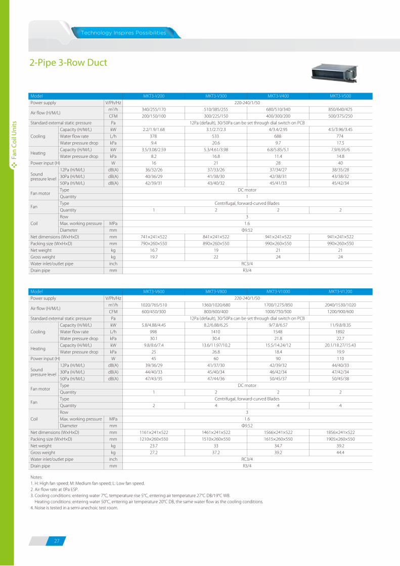
2-Pipe 3-Row Duct
Notes:1. H: High fan speed; M: Medium fan speed; L: Low fan speed.2. Air flow rate at 0Pa ESP. 3. Cooling conditions: entering water 7°C, temperature rise 5°C, entering air temperature 27°C DB/19°C WB. Heating conditions: entering water 50°C, entering air temperature 20°C DB, the same water flow as the cooling conditions.4. Noise is tested in a semi-anechoic test room.
Model
Power supply
Standard external static pressure
Cooling
Power input (H)
Coil
Net dimensions (W×H×D)
Packing size (W×H×D)
Net weight
Gross weight
Water inlet/outlet pipe
Drain pipe
Capacity (H/M/L)
Water flow rate
Water pressure drop
Capacity (H/M/L)
Water pressure drop
12Pa (H/M/L)
30Pa (H/M/L)
50Pa (H/M/L)
Type
Quantity
Type
Quantity
Row
Max. working pressure
Diameter
V/Ph/Hz
m3/h
CFM
Pa
kW
L/h
kPa
kW
kPa
W
dB(A)
dB(A)
dB(A)
MPa
mm
mm
mm
kg
kg
inch
mm
MKT3-V200
340/255/170
200/150/100
2.2/1.9/1.68
378
9.4
3.5/3.08/2.59
8.2
16
36/32/26
40/36/29
42/39/31
1
741×241×522
790×260×550
16.7
19.7
MKT3-V300
510/385/255
300/225/150
3.1/2.7/2.3
533
20.6
5.3/4.61/3.98
16.8
21
37/33/26
41/38/30
43/40/32
2
841×241×522
890×260×550
19
22
MKT3-V400
680/510/340
400/300/200
4/3.4/2.95
688
9.7
6.8/5.85/5.1
11.4
28
37/34/27
42/38/31
45/41/33
2
941×241×522
990×260×550
21
24
MKT3-V500
850/640/425
500/375/250
4.5/3.96/3.45
774
17.5
7.9/6.95/6
14.8
40
38/35/28
43/38/32
45/42/34
2
941×241×522
990×260×550
21
24
Model
Power supply
Standard external static pressure
Cooling
Power input (H)
Coil
Net dimensions (W×H×D)
Packing size (W×H×D)
Net weight
Gross weight
Water inlet/outlet pipe
Drain pipe
Capacity (H/M/L)
Water flow rate
Water pressure drop
Capacity (H/M/L)
Water pressure drop
12Pa (H/M/L)
30Pa (H/M/L)
50Pa (H/M/L)
Type
Quantity
Type
Quantity
Row
Max. working pressure
Diameter
V/Ph/Hz
m3/h
CFM
Pa
kW
L/h
kPa
kW
kPa
W
dB(A)
dB(A)
dB(A)
MPa
mm
mm
mm
kg
kg
inch
mm
MKT3-V600
1020/765/510
600/450/300
5.8/4.88/4.45
998
30.1
9.8/8.6/7.4
25
45
39/36/29
44/40/33
47/43/35
1
2
1161×241×522
1210×260×550
23.7
27.2
MKT3-V800
1360/1020/680
800/600/400
8.2/6.88/6.25
1410
30.4
13.6/11.97/10.2
26.8
60
41/37/30
45/40/34
47/44/36
2
4
1461×241×522
1510×260×550
33
37.2
MKT3-V1000
1700/1275/850
1000/750/500
9/7.8/6.57
1548
21.8
15.5/14.24/12
18.4
90
42/39/32
46/42/34
50/45/37
2
4
1566×241×522
1615×260×550
34.7
39.2
MKT3-V1200
2040/1530/1020
1200/900/600
11/9.8/8.35
1892
22.7
20.1/18.27/15.43
19.9
110
44/40/33
47/42/34
50/45/38
2
4
1856×241×522
1905×260×550
39.2
44.4
220-240/1/50
12Pa (default), 30/50Pa can be set through dial switch on PCB
DC motor
Centrifugal, forward-curved Blades
3
1.6
Φ9.52
RC3/4
R3/4
220-240/1/50
12Pa (default), 30/50Pa can be set through dial switch on PCB
DC motor
1
Centrifugal, forward-curved Blades
4
1.6
Φ9.52
RC3/4
R3/4
2-Pipe 4-Row Duct
Notes:1. H: High fan speed; M: Medium fan speed; L: Low fan speed.2. Air flow rate at 0Pa ESP. 3. Cooling conditions: entering water 7°C, temperature rise 5°C, entering air temperature 27°C DB/19°C WB. Heating conditions: entering water 50°C, entering air temperature 20°C DB, the same water flow as the cooling conditions.4. Noise is tested in a semi-anechoic test room.
Model
Power supply
Standard external static pressure
Cooling
Power input (H)
Coil
Net dimensions (W×H×D)
Packing size (W×H×D)
Net weight
Gross weight
Water inlet/outlet pipe
Drain pipe
Capacity (H/M/L)
Water flow rate
Water pressure drop
Capacity (H/M/L)
Water pressure drop
12Pa (H/M/L)
30Pa (H/M/L)
50Pa (H/M/L)
Type
Quantity
Type
Quantity
Row
Max. working pressure
Diameter
V/Ph/Hz
m3/h
CFM
Pa
kW
L/h
kPa
kW
kPa
W
dB(A)
dB(A)
dB(A)
MPa
mm
mm
mm
kg
kg
inch
mm
MKT4-V200
340/255/170
200/150/100
2.5/2.16/1.87
430
2
4.1/3.51/3.03
5.6
20
37/33/27
41/36/30
43/39/31
1
741×241×522
790×260×550
17.8
20.4
MKT4-V300
510/385/255
300/225/150
3.3/2.85/2.47
568
4.8
5.8/5.05/4.35
9.7
26
37/33/26
41/38/30
43/40/32
2
841×241×522
890×260×550
20
22.9
MKT4-V400
680/510/340
400/300/200
4.4/3.72/3.22
757
9.3
7.1/6.11/5.33
17.7
38
38/35/27
42/38/31
45/42/33
2
941×241×522
990×260×550
21.9
25.1
MKT4-V500
850/640/425
500/375/250
4.8/4.18/3.64
826
9.6
8.5/7.04/6.28
18.9
48
38/35/28
43/38/32
46/42/34
2
941×241×522
990×260×550
21.9
25.1
Model
Power supply
Standard external static pressure
Cooling
Power input (H)
Coil
Net dimensions (W×H×D)
Packing size (W×H×D)
Net weight
Gross weight
Water inlet/outlet pipe
Drain pipe
Capacity (H/M/L)
Water flow rate
Water pressure drop
Capacity (H/M/L)
Water pressure drop
12Pa (H/M/L)
30Pa (H/M/L)
50Pa (H/M/L)
Type
Quantity
Type
Quantity
Row
Max. working pressure
Diameter
V/Ph/Hz
m3/h
CFM
Pa
kW
L/h
kPa
kW
kPa
W
dB(A)
dB(A)
dB(A)
MPa
mm
mm
mm
kg
kg
inch
mm
MKT4-V600
1020/765/510
600/450/300
6.2/5.38/4.65
1066
18.8
10.5/9.03/7.77
11.6
54
39/36/29
44/40/33
47/43/35
1
2
1161×241×522
1210×260×550
25
28.8
MKT4-V800
1360/1020/680
800/600/400
8.8/7.43/6.57
1514
12.5
14.5/12.38/10.88
10.6
74
41/37/30
45/40/34
47/44/36
2
4
1461×241×522
1510×260×550
34.8
39.2
MKT4-V1000
1700/1275/850
1000/750/500
9.5/8.18/7.06
1634
14.5
16.3/13.45/12.05
18.4
99
42/39/32
46/42/35
50/45/37
2
4
1566×241×522
1615×260×550
36.4
41.9
MKT4-V1200
2040/1530/1020
1200/900/600
11.8/9.82/8.74
2030
23.1
20.1/16.72/14.88
22.8
135
44/40/33
47/42/35
50/45/38
2
4
1856×241×522
1905×260×550
41.9
47.2
220-240/1/50
12Pa (default), 30/50Pa can be set through dial switch on PCB
DC motor
Centrifugal, forward-curved Blades
4
1.6
Φ9.52
RC3/4
R3/4
Fan
Coil
Uni
ts
Fan
Coil
Uni
ts
Air flow (H/M/L)
Heating
Sound pressure level
Fan motor
Fan
Air flow (H/M/L)
Heating
Sound pressure level
Fan motor
Fan
Air flow (H/M/L)
Heating
Sound pressure level
Fan motor
Fan
Air flow (H/M/L)
Heating
Sound pressure level
Fan motor
Fan
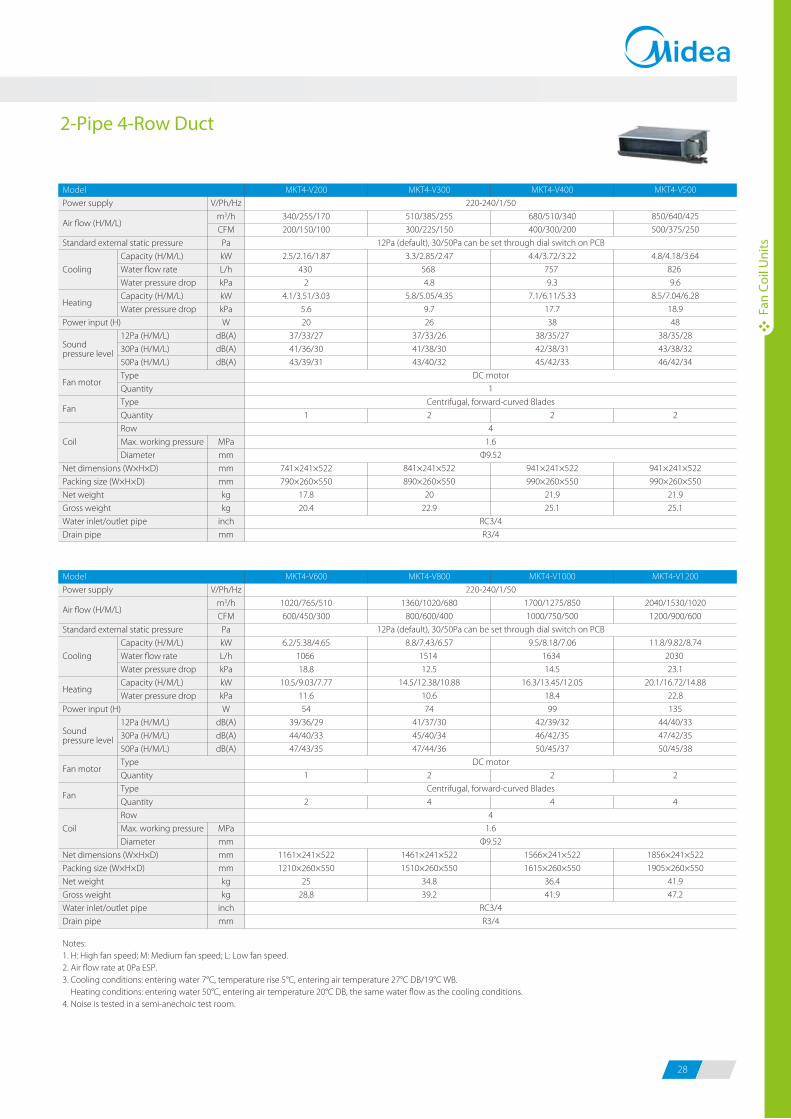
27 28
220-240/1/50
12Pa (default), 30/50Pa can be set through dial switch on PCB
DC motor
1
Centrifugal, forward-curved Blades
3
1.6
Φ9.52
RC3/4
R3/4
2-Pipe 3-Row Duct
Notes:1. H: High fan speed; M: Medium fan speed; L: Low fan speed.2. Air flow rate at 0Pa ESP. 3. Cooling conditions: entering water 7°C, temperature rise 5°C, entering air temperature 27°C DB/19°C WB. Heating conditions: entering water 50°C, entering air temperature 20°C DB, the same water flow as the cooling conditions.4. Noise is tested in a semi-anechoic test room.
Model
Power supply
Standard external static pressure
Cooling
Power input (H)
Coil
Net dimensions (W×H×D)
Packing size (W×H×D)
Net weight
Gross weight
Water inlet/outlet pipe
Drain pipe
Capacity (H/M/L)
Water flow rate
Water pressure drop
Capacity (H/M/L)
Water pressure drop
12Pa (H/M/L)
30Pa (H/M/L)
50Pa (H/M/L)
Type
Quantity
Type
Quantity
Row
Max. working pressure
Diameter
V/Ph/Hz
m3/h
CFM
Pa
kW
L/h
kPa
kW
kPa
W
dB(A)
dB(A)
dB(A)
MPa
mm
mm
mm
kg
kg
inch
mm
MKT3-V200
340/255/170
200/150/100
2.2/1.9/1.68
378
9.4
3.5/3.08/2.59
8.2
16
36/32/26
40/36/29
42/39/31
1
741×241×522
790×260×550
16.7
19.7
MKT3-V300
510/385/255
300/225/150
3.1/2.7/2.3
533
20.6
5.3/4.61/3.98
16.8
21
37/33/26
41/38/30
43/40/32
2
841×241×522
890×260×550
19
22
MKT3-V400
680/510/340
400/300/200
4/3.4/2.95
688
9.7
6.8/5.85/5.1
11.4
28
37/34/27
42/38/31
45/41/33
2
941×241×522
990×260×550
21
24
MKT3-V500
850/640/425
500/375/250
4.5/3.96/3.45
774
17.5
7.9/6.95/6
14.8
40
38/35/28
43/38/32
45/42/34
2
941×241×522
990×260×550
21
24
Model
Power supply
Standard external static pressure
Cooling
Power input (H)
Coil
Net dimensions (W×H×D)
Packing size (W×H×D)
Net weight
Gross weight
Water inlet/outlet pipe
Drain pipe
Capacity (H/M/L)
Water flow rate
Water pressure drop
Capacity (H/M/L)
Water pressure drop
12Pa (H/M/L)
30Pa (H/M/L)
50Pa (H/M/L)
Type
Quantity
Type
Quantity
Row
Max. working pressure
Diameter
V/Ph/Hz
m3/h
CFM
Pa
kW
L/h
kPa
kW
kPa
W
dB(A)
dB(A)
dB(A)
MPa
mm
mm
mm
kg
kg
inch
mm
MKT3-V600
1020/765/510
600/450/300
5.8/4.88/4.45
998
30.1
9.8/8.6/7.4
25
45
39/36/29
44/40/33
47/43/35
1
2
1161×241×522
1210×260×550
23.7
27.2
MKT3-V800
1360/1020/680
800/600/400
8.2/6.88/6.25
1410
30.4
13.6/11.97/10.2
26.8
60
41/37/30
45/40/34
47/44/36
2
4
1461×241×522
1510×260×550
33
37.2
MKT3-V1000
1700/1275/850
1000/750/500
9/7.8/6.57
1548
21.8
15.5/14.24/12
18.4
90
42/39/32
46/42/34
50/45/37
2
4
1566×241×522
1615×260×550
34.7
39.2
MKT3-V1200
2040/1530/1020
1200/900/600
11/9.8/8.35
1892
22.7
20.1/18.27/15.43
19.9
110
44/40/33
47/42/34
50/45/38
2
4
1856×241×522
1905×260×550
39.2
44.4
220-240/1/50
12Pa (default), 30/50Pa can be set through dial switch on PCB
DC motor
Centrifugal, forward-curved Blades
3
1.6
Φ9.52
RC3/4
R3/4
220-240/1/50
12Pa (default), 30/50Pa can be set through dial switch on PCB
DC motor
1
Centrifugal, forward-curved Blades
4
1.6
Φ9.52
RC3/4
R3/4
2-Pipe 4-Row Duct
Notes:1. H: High fan speed; M: Medium fan speed; L: Low fan speed.2. Air flow rate at 0Pa ESP. 3. Cooling conditions: entering water 7°C, temperature rise 5°C, entering air temperature 27°C DB/19°C WB. Heating conditions: entering water 50°C, entering air temperature 20°C DB, the same water flow as the cooling conditions.4. Noise is tested in a semi-anechoic test room.
Model
Power supply
Standard external static pressure
Cooling
Power input (H)
Coil
Net dimensions (W×H×D)
Packing size (W×H×D)
Net weight
Gross weight
Water inlet/outlet pipe
Drain pipe
Capacity (H/M/L)
Water flow rate
Water pressure drop
Capacity (H/M/L)
Water pressure drop
12Pa (H/M/L)
30Pa (H/M/L)
50Pa (H/M/L)
Type
Quantity
Type
Quantity
Row
Max. working pressure
Diameter
V/Ph/Hz
m3/h
CFM
Pa
kW
L/h
kPa
kW
kPa
W
dB(A)
dB(A)
dB(A)
MPa
mm
mm
mm
kg
kg
inch
mm
MKT4-V200
340/255/170
200/150/100
2.5/2.16/1.87
430
2
4.1/3.51/3.03
5.6
20
37/33/27
41/36/30
43/39/31
1
741×241×522
790×260×550
17.8
20.4
MKT4-V300
510/385/255
300/225/150
3.3/2.85/2.47
568
4.8
5.8/5.05/4.35
9.7
26
37/33/26
41/38/30
43/40/32
2
841×241×522
890×260×550
20
22.9
MKT4-V400
680/510/340
400/300/200
4.4/3.72/3.22
757
9.3
7.1/6.11/5.33
17.7
38
38/35/27
42/38/31
45/42/33
2
941×241×522
990×260×550
21.9
25.1
MKT4-V500
850/640/425
500/375/250
4.8/4.18/3.64
826
9.6
8.5/7.04/6.28
18.9
48
38/35/28
43/38/32
46/42/34
2
941×241×522
990×260×550
21.9
25.1
Model
Power supply
Standard external static pressure
Cooling
Power input (H)
Coil
Net dimensions (W×H×D)
Packing size (W×H×D)
Net weight
Gross weight
Water inlet/outlet pipe
Drain pipe
Capacity (H/M/L)
Water flow rate
Water pressure drop
Capacity (H/M/L)
Water pressure drop
12Pa (H/M/L)
30Pa (H/M/L)
50Pa (H/M/L)
Type
Quantity
Type
Quantity
Row
Max. working pressure
Diameter
V/Ph/Hz
m3/h
CFM
Pa
kW
L/h
kPa
kW
kPa
W
dB(A)
dB(A)
dB(A)
MPa
mm
mm
mm
kg
kg
inch
mm
MKT4-V600
1020/765/510
600/450/300
6.2/5.38/4.65
1066
18.8
10.5/9.03/7.77
11.6
54
39/36/29
44/40/33
47/43/35
1
2
1161×241×522
1210×260×550
25
28.8
MKT4-V800
1360/1020/680
800/600/400
8.8/7.43/6.57
1514
12.5
14.5/12.38/10.88
10.6
74
41/37/30
45/40/34
47/44/36
2
4
1461×241×522
1510×260×550
34.8
39.2
MKT4-V1000
1700/1275/850
1000/750/500
9.5/8.18/7.06
1634
14.5
16.3/13.45/12.05
18.4
99
42/39/32
46/42/35
50/45/37
2
4
1566×241×522
1615×260×550
36.4
41.9
MKT4-V1200
2040/1530/1020
1200/900/600
11.8/9.82/8.74
2030
23.1
20.1/16.72/14.88
22.8
135
44/40/33
47/42/35
50/45/38
2
4
1856×241×522
1905×260×550
41.9
47.2
220-240/1/50
12Pa (default), 30/50Pa can be set through dial switch on PCB
DC motor
Centrifugal, forward-curved Blades
4
1.6
Φ9.52
RC3/4
R3/4
Fan
Coil
Uni
ts
Fan
Coil
Uni
ts
Air flow (H/M/L)
Heating
Sound pressure level
Fan motor
Fan
Air flow (H/M/L)
Heating
Sound pressure level
Fan motor
Fan
Air flow (H/M/L)
Heating
Sound pressure level
Fan motor
Fan
Air flow (H/M/L)
Heating
Sound pressure level
Fan motor
Fan
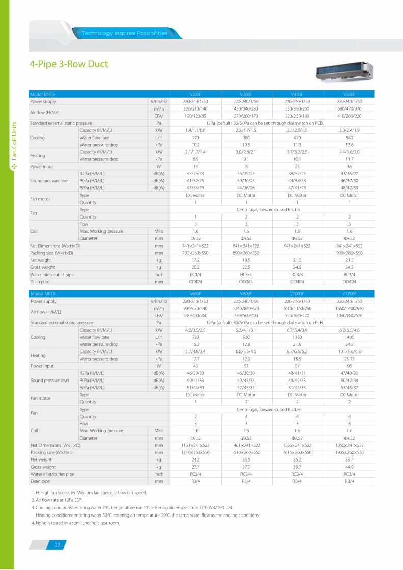
29 30
4-Pipe 3-Row Duct
Fan
Coil
Uni
ts
Fan
Coil
Uni
ts
1. H: High fan speed; M: Medium fan speed; L: Low fan speed.
2. Air flow rate at 12Pa ESP.
3. Cooling conditions: entering water 7°C, temperature rise 5°C, entering air temperature 27°C WB/19°C DB.
Heating conditions: entering water 50°C, entering air temperature 20°C, the same water flow as the cooling conditions.
4. Noise is tested in a semi-anechoic test room.
Stylish front panel blends easily within any interior décor, ideal for use in shops, restaurants or offices with no or narrow false
ceilings.
Stylish Panel
Built-In 3-Way Electromagnetic Valve
Auto Swing Louver
Easy Maintenance
The Auto Swing Louver function ensures that the air direction corresponds to the mode selected.
Removable front panel making maintenance convenient.
C Type S Type
Multi-directional outlet pipe feature: left\right\rear, to meet the needs of different rooms.
Convenient Installation
1
2
3
4
Step
Swing
Wall Mounted
Due to the DC brushless fan motor, the unit operates in high efficiency and low sound level.
High E�ciency and Low Sound Operation
Open panel
Rear
RightLeft
V200F V300F V400F V500F
V/Ph/Hz 220-240/1/50 220-240/1/50 220-240/1/50 220-240/1/50
m3/h 320/210/140 450/340/280 530/390/260 690/470/370
CFM 190/120/85 270/200/170 320/230/160 410/280/220
Pa
Capacity (H/M/L) kW 1.4/1.1/0.8 2.2/1.7/1.5 2.5/2.0/1.5 3.0/2.4/1.9
Water flow rate L/h 270 380 470 540
Water pressure drop kPa 10.2 10.5 11.3 13.6
Capacity (H/M/L) kW 2.1/1.7/1.4 3.0/2.6/2.1 3.7/3.2/2.5 4.4/3.6/3.0
Water pressure drop kPa 8.9 9.1 10.1 11.7
W 14 19 24 36
12Pa (H/M/L) dB(A) 35/25/23 36/29/23 38/32/24 43/35/27
30Pa (H/M/L) dB(A) 41/32/25 39/30/25 44/38/28 46/37/30
50Pa (H/M/L) dB(A) 43/34/26 44/36/26 47/41/28 48/42/33
DC Motor DC Motor DC Motor DC Motor
1 1 1 1
1 2 2 2
3 3 3 3
MPa 1.6 1.6 1.6 1.6
mm Φ9.52 Φ9.52 Φ9.52 Φ9.52
mm 741×241×522 841×241×522 941×241×522 941×241×522
mm 790×260×550 890×260×550 990×260×550
kg 17.2 19.5 21.5 21.5
kg 20.2 22.5 24.5 24.5
inch RC3/4 RC3/4 RC3/4 RC3/4
mm ODΦ24 ODΦ24 ODΦ24 ODΦ24
Model MKT3-
Air flow (H/M/L)
Power input
Heating
Power supply
Standard external static pressure
Gross weight
Water inlet/outlet pipe
Drain pipe
Sound pressure level
Cooling
12Pa (default), 30/50Pa can be set through dial switch on PCB.
Packing size (W×H×D)
Net Dimensions (W×H×D)
Net weight
Centrifugal, forward-curved BladesFan
Type
Quantity
Fan motorType
Quantity
Diameter
Coil
Row
Max. Working pressure
V600F V800F V1000F V1200F
V/Ph/Hz 220-240/1/50 220-240/1/50 220-240/1/50 220-240/1/50
m3/h 900/670/440 1240/840/670 1610/1160/790 1850/1400/970
CFM 530/400/260 730/500/400 950/690/470 1090/830/570
Pa
Capacity (H/M/L) kW 4.2/3.5/2.5 5.3/4.1/3.1 6.7/5.4/3.9 8.2/6.5/4.6
Water flow rate L/h 730 930 1180 1400
Water pressure drop kPa 15.3 12.8 21.6 34.9
Capacity (H/M/L) kW 5.7/4.8/3.4 6.8/5.5/4.6 8.2/6.9/5.2 10.1/8.6/6.8
Water pressure drop kPa 12.7 12.0 15.5 25.73
W 45 57 87 95
12Pa (H/M/L) dB(A) 46/39/30 46/38/30 48/41/31 47/40/30
30Pa (H/M/L) dB(A) 49/41/33 49/43/33 49/42/33 50/42/34
50Pa (H/M/L) dB(A) 51/44/39 52/45/37 51/44/35 53/45/37
DC Motor DC Motor DC Motor DC Motor
1 2 2 2
2 4 4 4
3 3 3 3
MPa 1.6 1.6 1.6 1.6
mm Φ9.52 Φ9.52 Φ9.52 Φ9.52
mm 1161×241×522 1461×241×522 1566×241×522 1856×241×522
mm 1210×260×550 1510×260×550 1615×260×550 1905×260×550
kg 24.2 33.5 35.2 39.7
kg 27.7 37.7 39.7 44.9
inch RC3/4 RC3/4 RC3/4 RC3/4
mm R3/4 R3/4 R3/4 R3/4
Model MKT3-
Air flow (H/M/L)
Power input
Heating
Power supply
Standard external static pressure
Gross weight
Water inlet/outlet pipe
Drain pipe
Sound pressure level
Cooling
12Pa (default), 30/50Pa can be set through dial switch on PCB.
Packing size (W×H×D)
Net Dimensions (W×H×D)
Net weight
Centrifugal, forward-curved BladesFan
Type
Quantity
Fan motorType
Quantity
Diameter
Coil
Row
Max. Working pressure
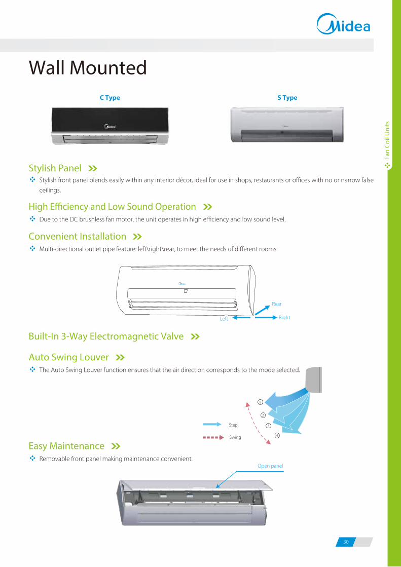
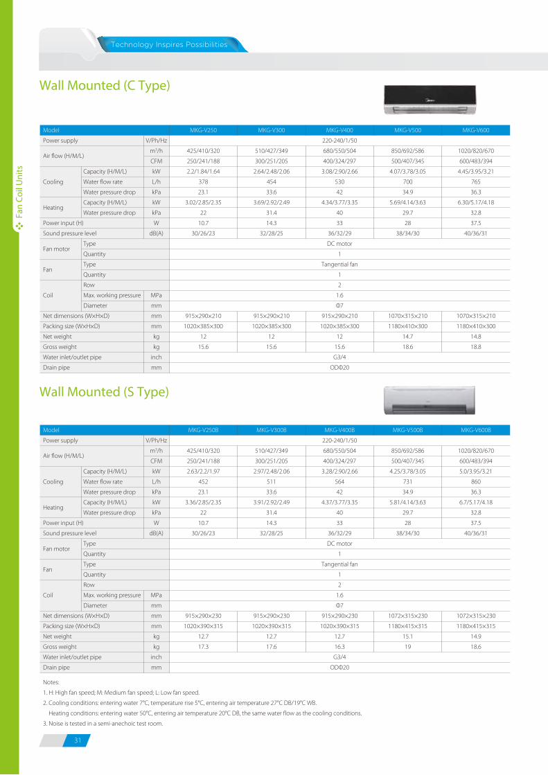
31 32
Fan
Coil
Uni
ts
Fan
Coil
Uni
ts
Due to the DC brushless fan motor, the unit operates in high efficiency and low sound level.
High E�ciency and Low Sound Operation
Flexible Air Return Type
Movable Louver
Air return can be from side or bottom.
Removable louver making maintenance convenient.
Concealed TypeH3 Series
Exposed Type (air return from side)
H4 Series
Exposed Type (air return from bottom)
H5 Series
Flexible InstallationCabinet and concealed versions meet various installation requirements.
Horizontal or vertical installation.
Ceiling installationFloor installation
Ceiling & FloorWall Mounted (C Type)
Wall Mounted (S Type)
Model
Power supply
Cooling
Power input (H)
Sound pressure level
Coil
Net dimensions (W×H×D)
Packing size (W×H×D)
Net weight
Gross weight
Water inlet/outlet pipe
Drain pipe
Capacity (H/M/L)
Water flow rate
Water pressure drop
Capacity (H/M/L)
Water pressure drop
Type
Quantity
Type
Quantity
Row
Max. working pressure
Diameter
V/Ph/Hz
m3/h
CFM
kW
L/h
kPa
kW
kPa
W
dB(A)
MPa
mm
mm
mm
kg
kg
inch
mm
MKG-V250
425/410/320
250/241/188
2.2/1.84/1.64
378
23.1
3.02/2.85/2.35
22
10.7
30/26/23
915×290×210
1020×385×300
12
15.6
MKG-V300
510/427/349
300/251/205
2.64/2.48/2.06
454
33.6
3.69/2.92/2.49
31.4
14.3
32/28/25
915×290×210
1020×385×300
12
15.6
MKG-V400
220-240/1/50
680/550/504
400/324/297
3.08/2.90/2.66
530
42
4.34/3.77/3.35
40
33
36/32/29
DC motor
1
Tangential fan
1
2
1.6
Φ7
915×290×210
1020×385×300
12
15.6
G3/4
ODΦ20
MKG-V500
850/692/586
500/407/345
4.07/3.78/3.05
700
34.9
5.69/4.14/3.63
29.7
28
38/34/30
1070×315×210
1180×410×300
14.7
18.6
MKG-V600
1020/820/670
600/483/394
4.45/3.95/3.21
765
36.3
6.30/5.17/4.18
32.8
37.5
40/36/31
1070×315×210
1180×410×300
14.8
18.8
Model
Power supply
Cooling
Power input (H)
Sound pressure level
Coil
Net dimensions (W×H×D)
Packing size (W×H×D)
Net weight
Gross weight
Water inlet/outlet pipe
Drain pipe
Capacity (H/M/L)
Water flow rate
Water pressure drop
Capacity (H/M/L)
Water pressure drop
Type
Quantity
Type
Quantity
Row
Max. working pressure
Diameter
V/Ph/Hz
m3/h
CFM
kW
L/h
kPa
kW
kPa
W
dB(A)
MPa
mm
mm
mm
kg
kg
inch
mm
MKG-V250B
425/410/320
250/241/188
2.63/2.2/1.97
452
23.1
3.36/2.85/2.35
22
10.7
30/26/23
915×290×230
1020×390×315
12.7
17.3
MKG-V300B
510/427/349
300/251/205
2.97/2.48/2.06
511
33.6
3.91/2.92/2.49
31.4
14.3
32/28/25
915×290×230
1020×390×315
12.7
17.6
MKG-V400B
220-240/1/50
680/550/504
400/324/297
3.28/2.90/2.66
564
42
4.37/3.77/3.35
40
33
36/32/29
DC motor
1
Tangential fan
1
2
1.6
Φ7
915×290×230
1020×390×315
12.7
16.3
G3/4
ODΦ20
MKG-V500B
850/692/586
500/407/345
4.25/3.78/3.05
731
34.9
5.81/4.14/3.63
29.7
28
38/34/30
1072×315×230
1180×415×315
15.1
19
MKG-V600B
1020/820/670
600/483/394
5.0/3.95/3.21
860
36.3
6.7/5.17/4.18
32.8
37.5
40/36/31
1072×315×230
1180×415×315
14.9
18.6
Notes:
1. H: High fan speed; M: Medium fan speed; L: Low fan speed.
2. Cooling conditions: entering water 7°C, temperature rise 5°C, entering air temperature 27°C DB/19°C WB.
Heating conditions: entering water 50°C, entering air temperature 20°C DB, the same water flow as the cooling conditions.
3. Noise is tested in a semi-anechoic test room.
Air flow (H/M/L)
Heating
Fan motor
Fan
Air flow (H/M/L)
Heating
Fan motor
Fan
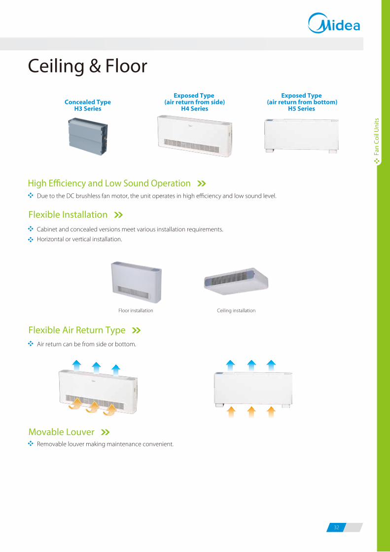
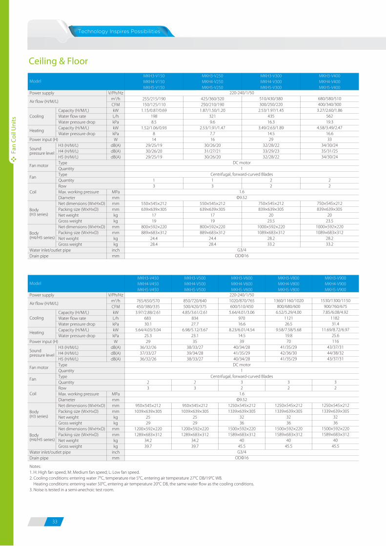
33 34
Ceiling & Floor
Power supply
Cooling
Power input (H)
Coil
Water inlet/outlet pipeDrain pipe
Capacity (H/M/L)Water flow rateWater pressure dropCapacity (H/M/L)Water pressure drop
H3 (H/M/L)H4 (H/M/L)H5 (H/M/L)TypeQuantityTypeQuantityRowMax. working pressureDiameterNet dimensions (W×H×D)Packing size (W×H×D)Net weightGross weightNet dimensions (W×H×D)Packing size (W×H×D)Net weightGross weight
V/Ph/Hzm3/hCFMkWL/hkPakWkPaW
dB(A)dB(A)dB(A)
MPammmmmmkgkg
mmmmkgkg
inchmm
255/215/190150/125/110
1.15/0.87/0.691988.5
1.52/1.06/0.938
1429/25/1930/26/2029/25/19
13
550×545×212639×639×305
1719
800×592×220889×683×312
24.428.4
425/360/320250/210/190
1.87/1.50/1.203219.6
2.53/1.91/1.477.716
30/26/2031/27/2130/26/20
13
550×545×212639×639×305
1719
800×592×220889×683×312
24.428.4
510/430/380300/250/220
2.53/1.97/1.4543516.3
3.49/2.63/1.8914.529
32/28/2233/29/2332/28/22
22
750×545×212839×639×305
2023.5
1000×592×2201089×683×312
28.233.2
680/580/510400/340/300
3.27/2.60/1.8656219.3
4.58/3.49/2.4716.633
34/30/2435/31/2534/30/24
22
750×545×212839×639×305
2023.5
1000×592×2201089×683×312
28.233.2
220-240/1/50
DC motor1
Centrifugal, forward-curved Blades
1.6Φ9.52
G3/4ODΦ16
MKH3-V150MKH4-V150MKH5-V150
MKH3-V250MKH4-V250MKH5-V250
MKH3-V300MKH4-V300MKH5-V300
MKH3-V400MKH4-V400MKH5-V400
Model
Air flow (H/M/L)
Heating
Sound pressure level
Fan motor
Fan
Body (H3 series)
Body (H4/H5 series)
Power supply
Power input (H)
Water inlet/outlet pipeDrain pipe
Capacity (H/M/L)Water flow rateWater pressure dropCapacity (H/M/L)Water pressure drop
H3 (H/M/L)H4 (H/M/L)H5 (H/M/L)TypeQuantityTypeQuantityRowMax. working pressureDiameterNet dimensions (W×H×D)Packing size (W×H×D)Net weightGross weightNet dimensions (W×H×D)Packing size (W×H×D)Net weightGross weight
V/Ph/Hzm3/hCFMkWL/hkPakWkPaW
dB(A)dB(A)dB(A)
MPammmmmmkgkg
mmmmkgkg
inchmm
MKH3-V450MKH4-V450MKH5-V450
MKH3-V500MKH4-V500MKH5-V500
MKH3-V600MKH4-V600MKH5-V600
MKH3-V800MKH4-V800MKH5-V800
MKH3-V900MKH4-V900MKH5-V900
Model
765/650/570450/380/335
3.97/2.88/2.61683 30.1
5.64/4.03/3.0425.329
36/32/2637/33/2736/32/26
23
950×545×2121039×639×305
2529
1200×592×2201289×683×312
34.239.7
850/720/640500/420/375
4.85/3.61/2.6183427.7
6.98/5.12/3.6723.135
38/33/2739/34/2838/33/27
23
950×545×2121039×639×305
2529
1200×592×2201289×683×312
34.239.7
220-240/1/501020/870/765600/510/450
5.64/4.01/3.0697016.6
8.23/6.01/4.5414.539
40/34/2841/35/2940/34/28DC motor
1Centrifugal, forward-curved Blades
32
1.6Φ9.52
1250×545×2121339×639×305
3236
1500×592×2201589×683×312
4045.5G3/4
ODΦ16
1360/1160/1020800/680/600
6.52/5.29/4.00112126.5
9.58/7.58/5.6819.870
41/35/2942/36/3041/35/29
32
1250×545×2121339×639×305
3236
1500×592×2201589×683×312
4045.5
1530/1300/1150900/760/675
7.85/6.08/4.921182 31.4
11.69/8.72/6.9725.6116
43/37/3144/38/3243/37/31
32
1250×545×2121339×639×305
3236
1500×592×2201589×683×312
4045.5
Notes:1. H: High fan speed; M: Medium fan speed; L: Low fan speed.2. Cooling conditions: entering water 7°C, temperature rise 5°C, entering air temperature 27°C DB/19°C WB. Heating conditions: entering water 50°C, entering air temperature 20°C DB, the same water flow as the cooling conditions.3. Noise is tested in a semi-anechoic test room.
Air flow (H/M/L)
Cooling
Heating
Sound pressure level
Fan motor
Fan
Coil
Body (H3 series)
Body (H4/H5 series)
Fan
Coil
Uni
ts
Fan
Coil
Uni
ts
680(
Hoo
k-lo
catio
n)
840(
Body
)
950(
Pane
l)
780(Hook-location)
840(Body)
950(Panel)
Drain sideTubing side
4-Pipe 4-way cassetteDimensions (unit:mm)
Service Spaces (unit:mm)
300
190 22
0
150
160
210
2-pipe 4-way cassetteDimensions (unit:mm)
680(
Hoo
k-lo
catio
n)
840(
Body
)
950(
Pane
l)
780(Hook-location)
840(Body)
950(Panel)
Drain sideTubing side
B
A
C D
300 190 145 195
SizeModel
230 170 135 185
A B C D
MKA-V950RMKA-V1200RMAK-V1500R
MKA-V600RMKA-V750R
Dimensions4-way cassette
>1000
>1000>
1000
>10
00
Ceiling
600mm (ceiling hole)
Ground
PanelInletOutlet Outlet
C
880 (ceiling hole)
>25
00
Water pipe jointDrain pipe joint
Ceiling
Ground
InletOutlet
330
2-pipe 4-way cassette
Ceiling
880 (ceiling hole)
Ground
InletOutlet Outlet
4000
~25
00
Water pipe jointDrain pipe joint
>33
0
4-pipe 4-way cassette
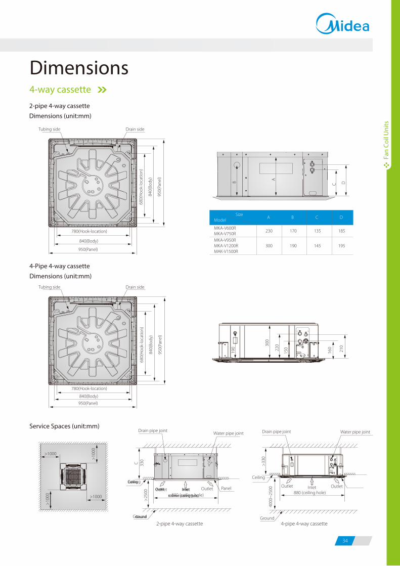
33 34
Ceiling & Floor
Power supply
Cooling
Power input (H)
Coil
Water inlet/outlet pipeDrain pipe
Capacity (H/M/L)Water flow rateWater pressure dropCapacity (H/M/L)Water pressure drop
H3 (H/M/L)H4 (H/M/L)H5 (H/M/L)TypeQuantityTypeQuantityRowMax. working pressureDiameterNet dimensions (W×H×D)Packing size (W×H×D)Net weightGross weightNet dimensions (W×H×D)Packing size (W×H×D)Net weightGross weight
V/Ph/Hzm3/hCFMkWL/hkPakWkPaW
dB(A)dB(A)dB(A)
MPammmmmmkgkg
mmmmkgkg
inchmm
255/215/190150/125/110
1.15/0.87/0.691988.5
1.52/1.06/0.938
1429/25/1930/26/2029/25/19
13
550×545×212639×639×305
1719
800×592×220889×683×312
24.428.4
425/360/320250/210/190
1.87/1.50/1.203219.6
2.53/1.91/1.477.716
30/26/2031/27/2130/26/20
13
550×545×212639×639×305
1719
800×592×220889×683×312
24.428.4
510/430/380300/250/220
2.53/1.97/1.4543516.3
3.49/2.63/1.8914.529
32/28/2233/29/2332/28/22
22
750×545×212839×639×305
2023.5
1000×592×2201089×683×312
28.233.2
680/580/510400/340/300
3.27/2.60/1.8656219.3
4.58/3.49/2.4716.633
34/30/2435/31/2534/30/24
22
750×545×212839×639×305
2023.5
1000×592×2201089×683×312
28.233.2
220-240/1/50
DC motor1
Centrifugal, forward-curved Blades
1.6Φ9.52
G3/4ODΦ16
MKH3-V150MKH4-V150MKH5-V150
MKH3-V250MKH4-V250MKH5-V250
MKH3-V300MKH4-V300MKH5-V300
MKH3-V400MKH4-V400MKH5-V400
Model
Air flow (H/M/L)
Heating
Sound pressure level
Fan motor
Fan
Body (H3 series)
Body (H4/H5 series)
Power supply
Power input (H)
Water inlet/outlet pipeDrain pipe
Capacity (H/M/L)Water flow rateWater pressure dropCapacity (H/M/L)Water pressure drop
H3 (H/M/L)H4 (H/M/L)H5 (H/M/L)TypeQuantityTypeQuantityRowMax. working pressureDiameterNet dimensions (W×H×D)Packing size (W×H×D)Net weightGross weightNet dimensions (W×H×D)Packing size (W×H×D)Net weightGross weight
V/Ph/Hzm3/hCFMkWL/hkPakWkPaW
dB(A)dB(A)dB(A)
MPammmmmmkgkg
mmmmkgkg
inchmm
MKH3-V450MKH4-V450MKH5-V450
MKH3-V500MKH4-V500MKH5-V500
MKH3-V600MKH4-V600MKH5-V600
MKH3-V800MKH4-V800MKH5-V800
MKH3-V900MKH4-V900MKH5-V900
Model
765/650/570450/380/335
3.97/2.88/2.61683 30.1
5.64/4.03/3.0425.329
36/32/2637/33/2736/32/26
23
950×545×2121039×639×305
2529
1200×592×2201289×683×312
34.239.7
850/720/640500/420/375
4.85/3.61/2.6183427.7
6.98/5.12/3.6723.135
38/33/2739/34/2838/33/27
23
950×545×2121039×639×305
2529
1200×592×2201289×683×312
34.239.7
220-240/1/501020/870/765600/510/450
5.64/4.01/3.0697016.6
8.23/6.01/4.5414.539
40/34/2841/35/2940/34/28DC motor
1Centrifugal, forward-curved Blades
32
1.6Φ9.52
1250×545×2121339×639×305
3236
1500×592×2201589×683×312
4045.5G3/4
ODΦ16
1360/1160/1020800/680/600
6.52/5.29/4.00112126.5
9.58/7.58/5.6819.870
41/35/2942/36/3041/35/29
32
1250×545×2121339×639×305
3236
1500×592×2201589×683×312
4045.5
1530/1300/1150900/760/675
7.85/6.08/4.921182 31.4
11.69/8.72/6.9725.6116
43/37/3144/38/3243/37/31
32
1250×545×2121339×639×305
3236
1500×592×2201589×683×312
4045.5
Notes:1. H: High fan speed; M: Medium fan speed; L: Low fan speed.2. Cooling conditions: entering water 7°C, temperature rise 5°C, entering air temperature 27°C DB/19°C WB. Heating conditions: entering water 50°C, entering air temperature 20°C DB, the same water flow as the cooling conditions.3. Noise is tested in a semi-anechoic test room.
Air flow (H/M/L)
Cooling
Heating
Sound pressure level
Fan motor
Fan
Coil
Body (H3 series)
Body (H4/H5 series)
Fan
Coil
Uni
ts
Fan
Coil
Uni
ts
680(
Hoo
k-lo
catio
n)
840(
Body
)
950(
Pane
l)
780(Hook-location)
840(Body)
950(Panel)
Drain sideTubing side
4-Pipe 4-way cassetteDimensions (unit:mm)
Service Spaces (unit:mm)
300
190 22
0
150
160
210
2-pipe 4-way cassetteDimensions (unit:mm)
680(
Hoo
k-lo
catio
n)
840(
Body
)
950(
Pane
l)
780(Hook-location)
840(Body)
950(Panel)
Drain sideTubing side
B
A
C D
300 190 145 195
SizeModel
230 170 135 185
A B C D
MKA-V950RMKA-V1200RMAK-V1500R
MKA-V600RMKA-V750R
Dimensions4-way cassette
>1000
>1000
>10
00
>10
00
Ceiling
600mm (ceiling hole)
Ground
PanelInletOutlet Outlet
C
880 (ceiling hole)
>25
00
Water pipe jointDrain pipe joint
Ceiling
Ground
InletOutlet
330
2-pipe 4-way cassette
Ceiling
880 (ceiling hole)
Ground
InletOutlet Outlet
4000
~25
00
Water pipe jointDrain pipe joint
>33
0
4-pipe 4-way cassette
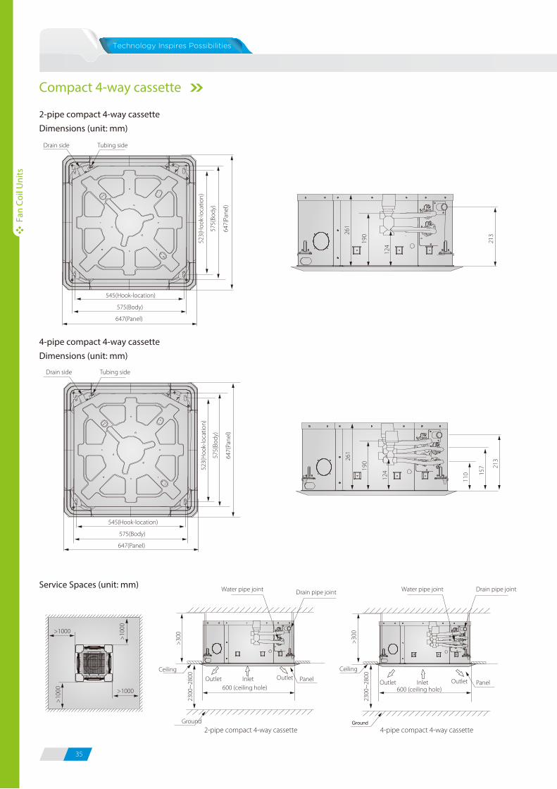
35 36
Fan
Coil
Uni
ts
Fan
Coil
Uni
ts
6082
618
H
Height of the front panel
Type H (mm)
4-way cassette 45
Compact 4-way cassette 50
Dimensions (unit: mm)
Dimensions (unit: mm)
Model MKG-V250-BMKG-V300-BMKG-V400-B
MKG-V500-BMKG-V600-BSize
A
B
D
C
732
915
663
290
892
1072
813
315
Model MKG-V250MKG-V300MKG-V400
MKG-V500MKG-V600Size
A
B
D
C
915
290
670
725
1070
315
815
885
90
210
84
60
CA
D112
65
42
48
66
290
69
75
A230B
114 D
25
C
Wall mounted - S type
Wall mounted - C type
2-pipe duct
241
water inletWater outlet
Air release valve
10140
180
241
180
258
128
F
262
5617
047
0 522
AB (Air return)
Terminal box
4-10×16 hanger slots
C
DE
11650
Drain port
4-pipe duct
241
Air release valve
10140
180
241
180
258
128
Drain portZG3/4” Cold water
inlet RC3/4”Hot waterinlet RC3/4”
Cold wateroutlet RC3/4”
Hot wateroutlet RC3/4”
Dimensions (unit: mm)
Duct
2-pipe compact 4-way cassetteDimensions (unit: mm)
4-pipe compact 4-way cassetteDimensions (unit: mm)
261
190
124
213
Tubing sideDrain side
523(
Hoo
k-lo
catio
n)
575(
Body
)
647(
Pane
l)
545(Hook-location)
575(Body)
647(Panel)
261
190
124
213
110 15
7
Tubing sideDrain side
523(
Hoo
k-lo
catio
n)
575(
Body
)
647(
Pane
l)
545(Hook-location)
575(Body)
647(Panel)
Service Spaces (unit: mm)
Ground2-pipe compact 4-way cassette 4-pipe compact 4-way cassette
>1000
>1000
>10
00
>10
00
Outlet
600 (ceiling hole)
2300
~28
00
Water pipe joint Drain pipe joint
Panel
Ceiling
InletOutlet
>30
0
2300
~28
00
Water pipe joint Drain pipe joint
Ceiling
Outlet600 (ceiling hole)
PanelInletOutlet
>30
0
Compact 4-way cassette
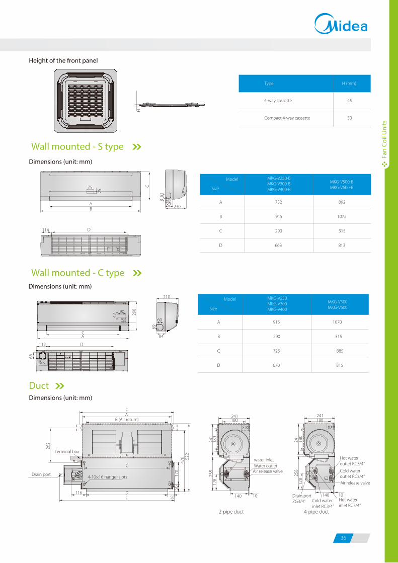
35 36
Fan
Coil
Uni
ts
Fan
Coil
Uni
ts
6082
618
H
Height of the front panel
Type H (mm)
4-way cassette 45
Compact 4-way cassette 50
Dimensions (unit: mm)
Dimensions (unit: mm)
Model MKG-V250-BMKG-V300-BMKG-V400-B
MKG-V500-BMKG-V600-BSize
A
B
D
C
732
915
663
290
892
1072
813
315
Model MKG-V250MKG-V300MKG-V400
MKG-V500MKG-V600Size
A
B
D
C
915
290
670
725
1070
315
815
885
90
210
84
60
CA
D112
65
42
48
66
290
69
75
A230B
114 D
25
CWall mounted - S type
Wall mounted - C type
2-pipe duct
241
water inletWater outlet
Air release valve
10140
180
241
180
258
128
F
262
5617
047
0 522
AB (Air return)
Terminal box
4-10×16 hanger slots
C
DE
11650
Drain port
4-pipe duct
241
Air release valve
10140
180
241
180
258
128
Drain portZG3/4” Cold water
inlet RC3/4”Hot waterinlet RC3/4”
Cold wateroutlet RC3/4”
Hot wateroutlet RC3/4”
Dimensions (unit: mm)
Duct
2-pipe compact 4-way cassetteDimensions (unit: mm)
4-pipe compact 4-way cassetteDimensions (unit: mm)
261
190
124
213
Tubing sideDrain side
523(
Hoo
k-lo
catio
n)
575(
Body
)
647(
Pane
l)
545(Hook-location)
575(Body)
647(Panel)
261
190
124
213
110 15
7
Tubing sideDrain side
523(
Hoo
k-lo
catio
n)
575(
Body
)
647(
Pane
l)
545(Hook-location)
575(Body)
647(Panel)
Service Spaces (unit: mm)
Ground2-pipe compact 4-way cassette 4-pipe compact 4-way cassette
>1000
>1000
>10
00
>10
00
Outlet
600 (ceiling hole)
2300
~28
00
Water pipe joint Drain pipe joint
Panel
Ceiling
InletOutlet
>30
0
2300
~28
00
Water pipe joint Drain pipe joint
Ceiling
Outlet600 (ceiling hole)
PanelInletOutlet
>30
0
Compact 4-way cassette
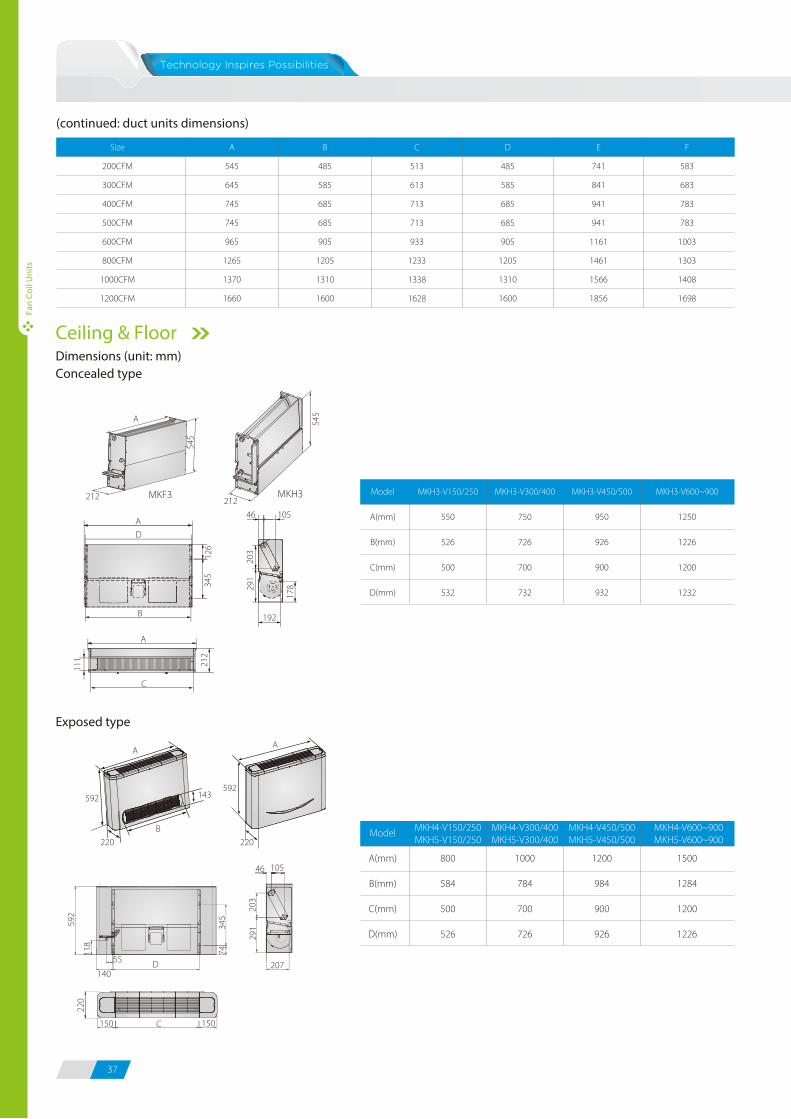
37 38
Fan
Coil
Uni
ts
Fan
Coil
Uni
ts
150
74118
140
203
345
592
220
291
AA
143
B
220
46 105
207D
C 150
55
220
592592
Exposed type
800
584
500
526
1000
784
700
726
1200
984
900
926
1500
1284
1200
1226
Model
A(mm)
B(mm)
C(mm)
D(mm)
MKH4-V150/250MKH5-V150/250
MKH4-V300/400MKH5-V300/400
MKH4-V450/500MKH5-V450/500
MKH4-V600~900MKH5-V600~900
MKH3-V150/250
550
526
500
532
MKH3-V300/400
750
726
700
732
MKH3-V450/500
950
926
900
932
MKH3-V600~900
1250
1226
1200
1232
Model
A(mm)
B(mm)
C(mm)
D(mm)
545
545
126
345
203
291
212
111
178
A
A105
192
46
D
B
A
C
212 212MKF3 MKH3
Dimensions (unit: mm)Concealed type
Ceiling & Floor
(continued: duct units dimensions)
Size
200CFM
300CFM
400CFM
500CFM
600CFM
800CFM
1000CFM
1200CFM
A
545
645
745
745
965
1265
1370
1660
B
485
585
685
685
905
1205
1310
1600
D
485
585
685
685
905
1205
1310
1600
E
741
841
941
941
1161
1461
1566
1856
F
583
683
783
783
1003
1303
1408
1698
C
513
613
713
713
933
1233
1338
1628
Centralized controllers
Control Devices
Wired controllers
Wireless remote controllers
Model Appearance
R05/BGE
Function Descriptions Applicable FCUs
4-way Cassette (standard)
Compact 4-way cassette (standard)
Wall mounted (standard)
LCD display screen
Mode control
Fan speeds control
Time setting / Temp. setting / Swing setting
Model Appearance
KJRP-86A1-E
KJR-18B/E
Function Descriptions Applicable FCUs
Duct without electric heater (optional)
Duct without electric heater (optional)
KJR-21B/D
KJR-15B/E
Duct with electric heater (optional)
Floor standing / Ceiling & floor (optional)
LCD display screen
Mode control
Fan speeds control
Timer setting / Temp. setting
Mechanical thermostat
Mode control
Fan speeds control
Temp. setting
LCD display screen
Mode control / Fan speeds control
Electric heater control
Temp. setting
LCD display screen
Mode control
Fan speeds control
Temperature display in oF or oC
KJR-29B/E Cassette / Wall-mounted (optional)
KJR-12B/E Cassette / Wall-mounted (optional)
Model Appearance
CCM03
CCM09
Function Descriptions Applicable FCUs
CCM30
Large LCD display screen
Max. of 64 FCUs can be controlled by a CCM03
Mode control / fan speed control
Time setting / temp. setting / swing setting
Weekly schedule function
Basic functions are same as CCM03
Touch-style keys
Basic functions are same as CCM03
All FCUs
(Compact 4-way cassette FCUs need adding NIM01 module,
non-PCB FCUs need adding PC board control kit)
LCD display screen
Mode control
Fan speeds control
Temp. setting
Swing function
Mode control
Fan speeds control
Temp. setting
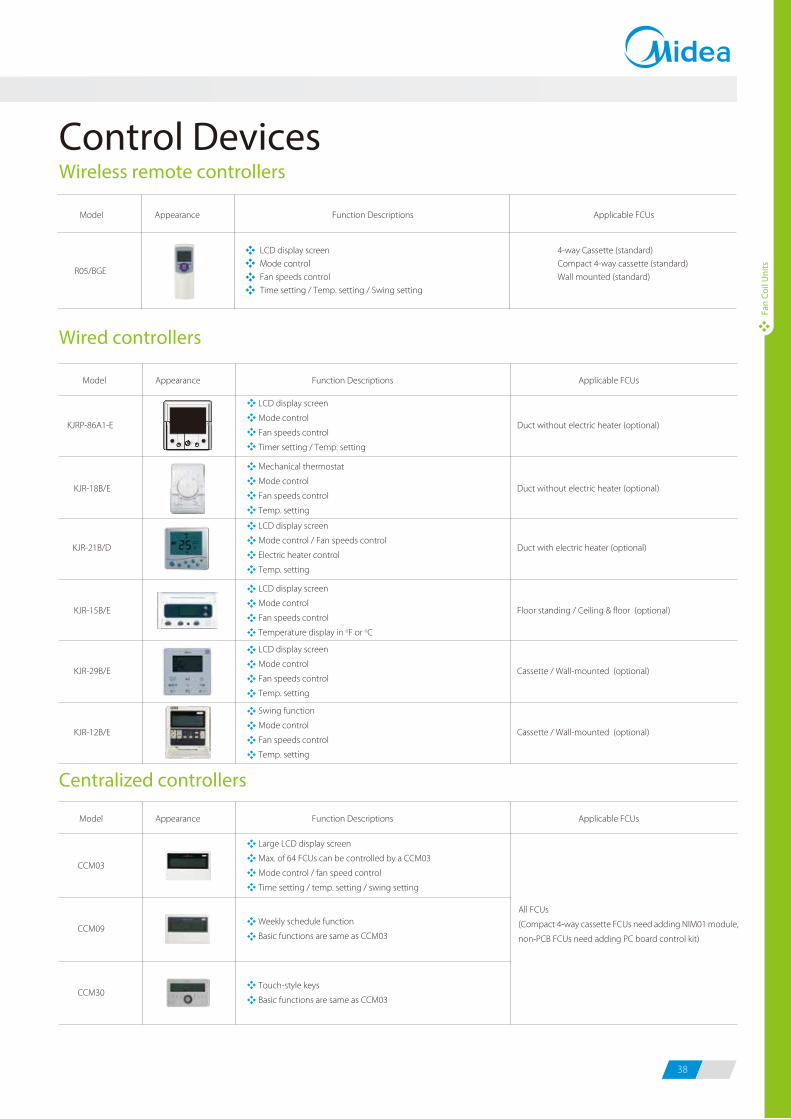
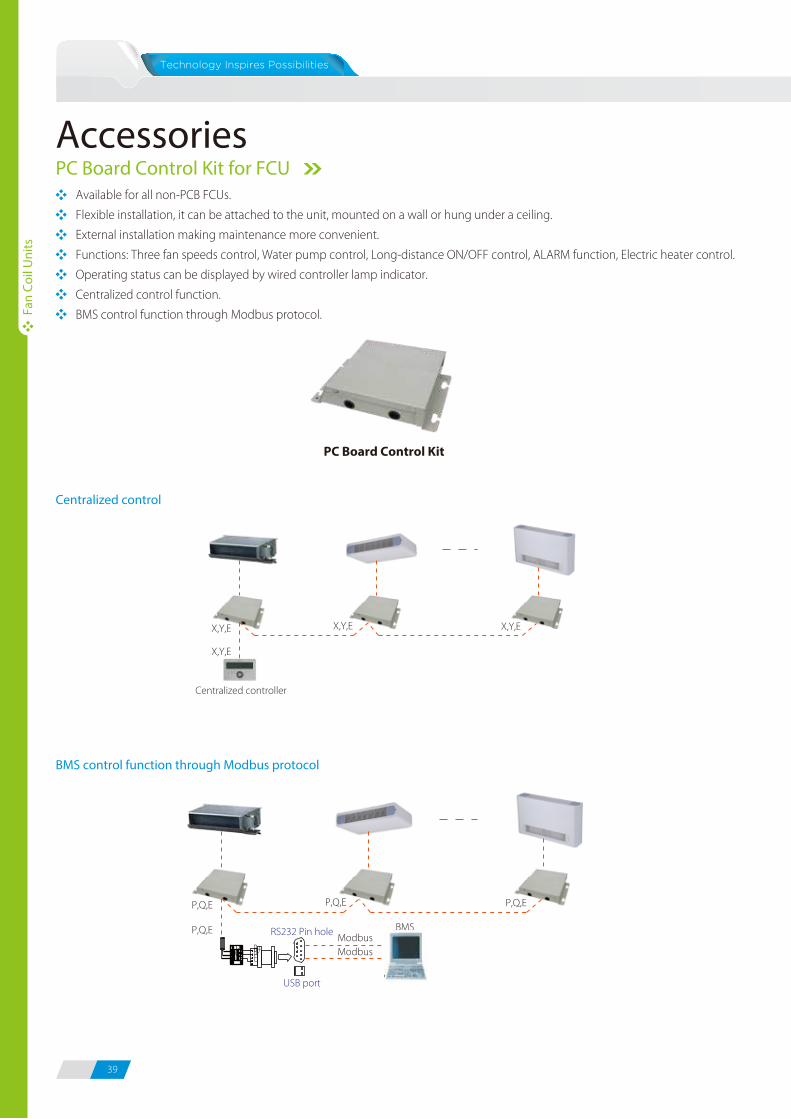
39 40
Fan
Coil
Uni
ts
Fan
Coil
Uni
ts
PC Board Control Kit for FCUAvailable for all non-PCB FCUs.
Flexible installation, it can be attached to the unit, mounted on a wall or hung under a ceiling.
External installation making maintenance more convenient.
Functions: Three fan speeds control, Water pump control, Long-distance ON/OFF control, ALARM function, Electric heater control.
Operating status can be displayed by wired controller lamp indicator.
Centralized control function.
BMS control function through Modbus protocol.
Centralized control
BMS control function through Modbus protocol
X,Y,E
X,Y,E
Centralized controller
X,Y,E X,Y,E
P,Q,E
P,Q,E RS232 Pin hole BMSModbusModbus
USB port
P,Q,E P,Q,E
EPQ R+R-
E
Model
Applicable appliance
Power supply
Operation range
Temp. controlling precision
Net dimension
Packing size
Net weight
Gross weight
Room temp.
Inlet water temp.
W×H×D
W×H×D
CE-FCUKZ-03
2-pipe FCUs
CE-FCUKZ-04
4-pipe FCUs
220~240-1-50/60
17-30
3-75
±1
296×66×212
410×115×262
1.4
2.5
V-Ph-Hz
oC
oC
oC
mm
mm
kg
kg
Accessories
Valve Kit
Working Voltage: AC230±10%, 50/60Hz(24V can be customized).
Power Consumption: 4W
Nominal Pressure: 1.6MPa.
Applied Medium: Cold or hot water, 50% glycol water liquor.
Medium Temperature: 2-15°C(DDSTF-01), -20-1°C(DDSTF-04/05).
Environment Temperature: -5-50°C(DDSTF-01), 0-50°C(DDSTF-04/05).
Model
DDSTF-01
DDSTF-04
DDSTF-05
DN(mm)
20
15
20
Inner Screw Thead
3/4”
1/2”
3/4”
Applicable Appliance
2-pipe cassette/duct/floor standing, 4-pipe duct
4-pipe cassette (for hot water)
2-pipe ceiling & floor, 4-pipe cassette (for cold water)
DDSTF-01 DDSTF-04DDSTF-05
PC Board Control Kit
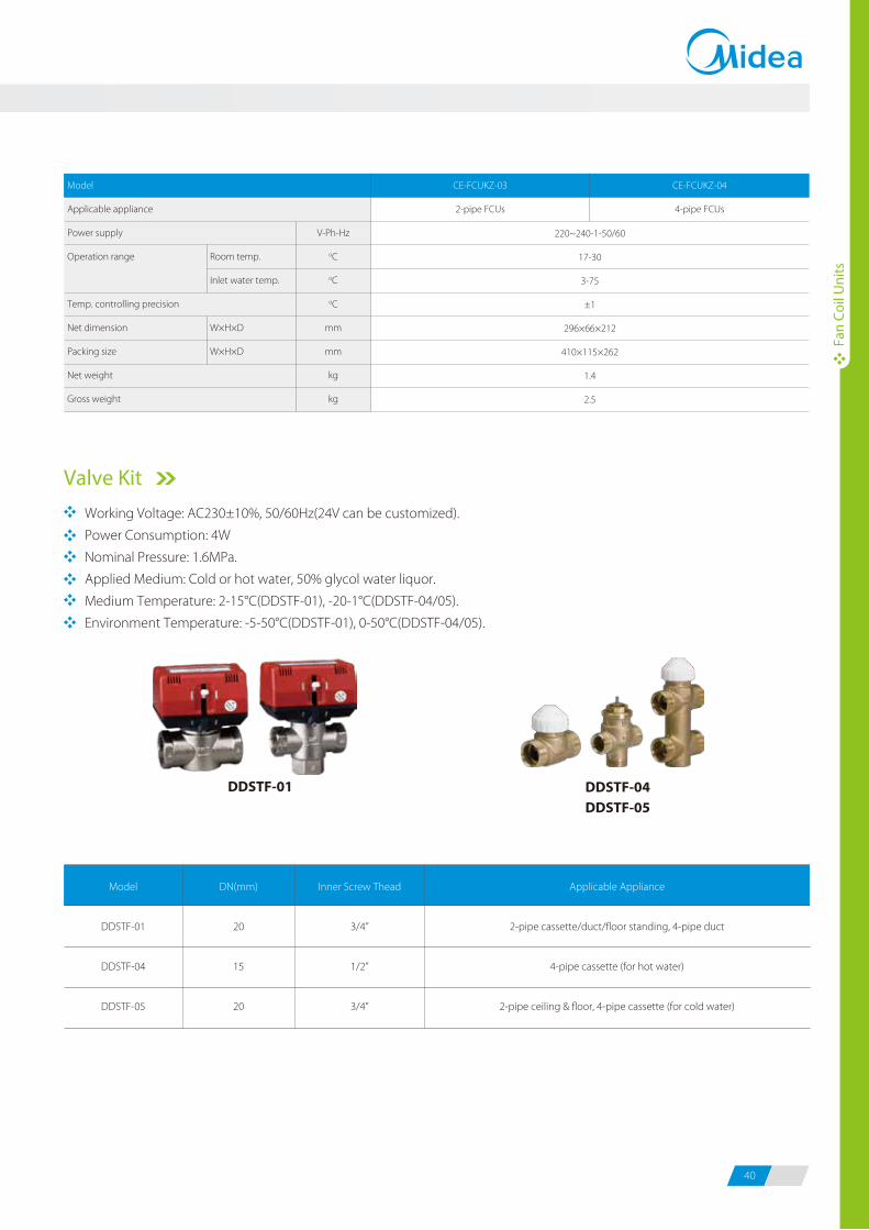
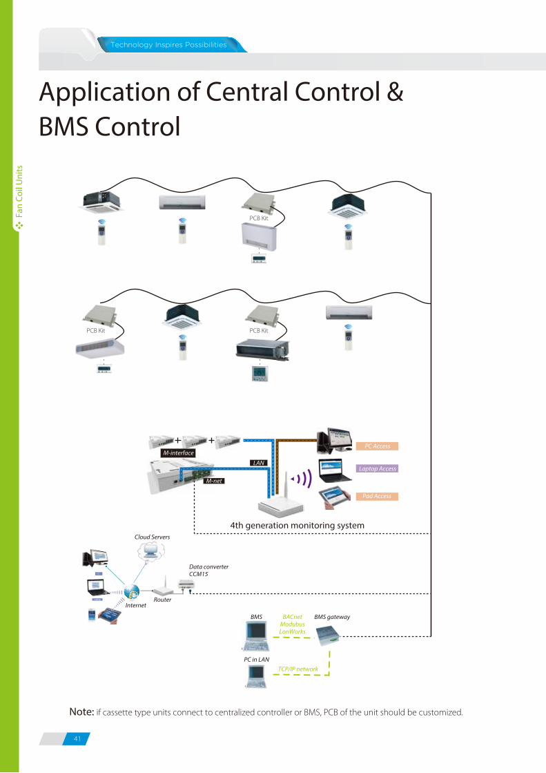
41 42
Application of Central Control & BMS Control
PC
BMS gatewayBMS
PC in LAN
BACnetModubusLonWorks
TCP/IP network
LAN
M-interface
Laptop Access
Pad Access
M-net
PC Access
PCB Kit
PCB Kit PCB Kit
Cloud Servers
InternetRouter
Data converter CCM15
4th generation monitoring system
Fan
Coil
Uni
ts
Fan
Coil
Uni
ts
Select by entering air and water conditions as well as fan speed.
Easy to operate interface and visual display.
Powerful project management function.
Features
Main Interface
Selection Software
Management Area Selection Area
Function Area
Add/Delete Unit
Note: if cassette type units connect to centralized controller or BMS, PCB of the unit should be customized.
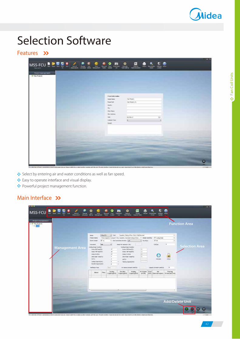
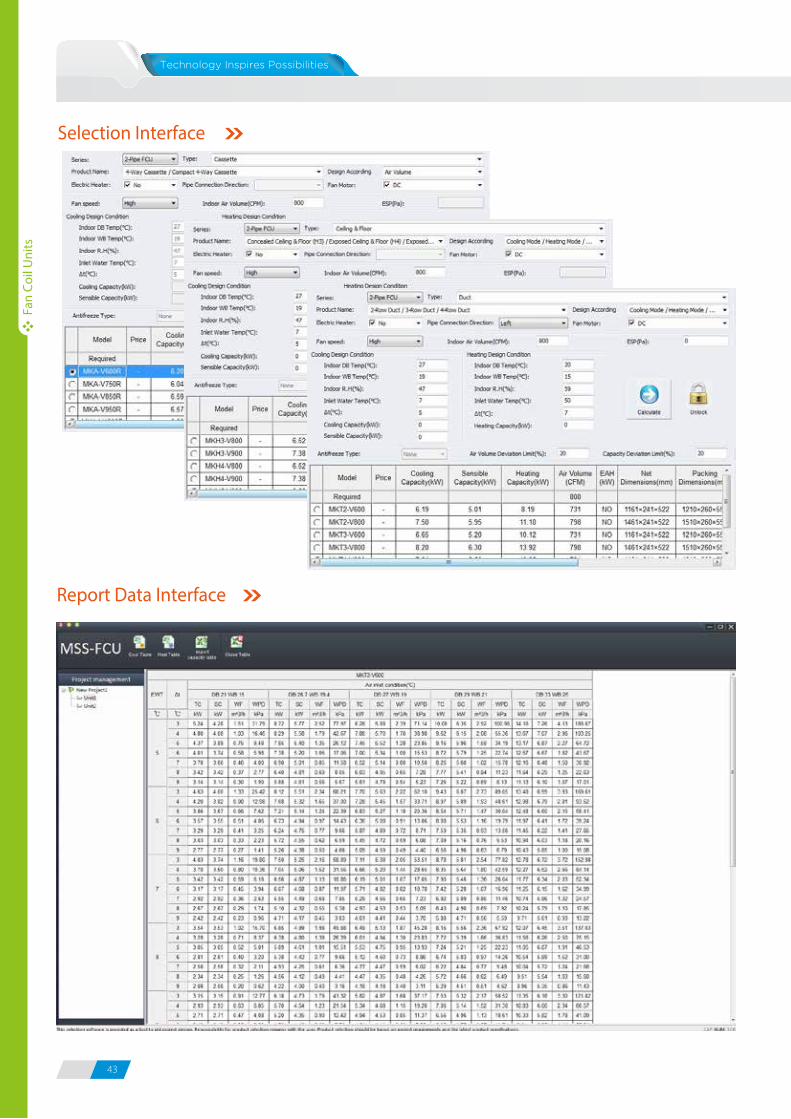
43 44
Fan
Coil
Uni
ts
Fan
Coil
Uni
ts
Selection Interface
Report Data Interface
43 44
Fan
Coil
Uni
ts
Fan
Coil
Uni
ts
Selection Interface
Report Data Interface
DC InverterAqua Mini Chillers & Fan Coil Units
INVERTER
1703-1C1702
iOS Version Android Version
Midea CAC After-service Application
iOS Version
Midea CAC News Application
Add.: Midea Headquarters Building, 6 Midea Avenue, Shunde, Foshan, Guangdong, China
Postal code: 528311
Tel: +86-757-26338346 Fax: +86-757-22390205
cac.midea.com global.midea.com
Note: Product speci�cations change from time to time as product improvements and
developments are released and may vary from those in this document.
Commercial Air Conditioner Division
Midea Group
Commercial Air Conditioners 2017/2018
Recommended