Co ordinate Measuring Machine(CMM)
ME0403‐Metrology and Quality Control
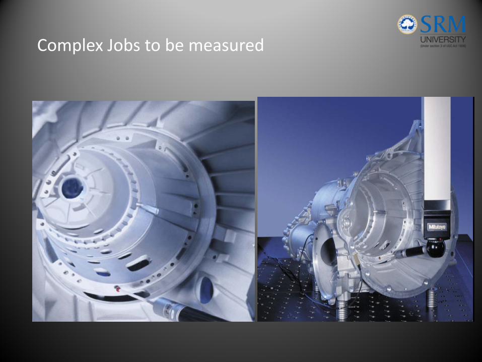
Complex Jobs to be measured
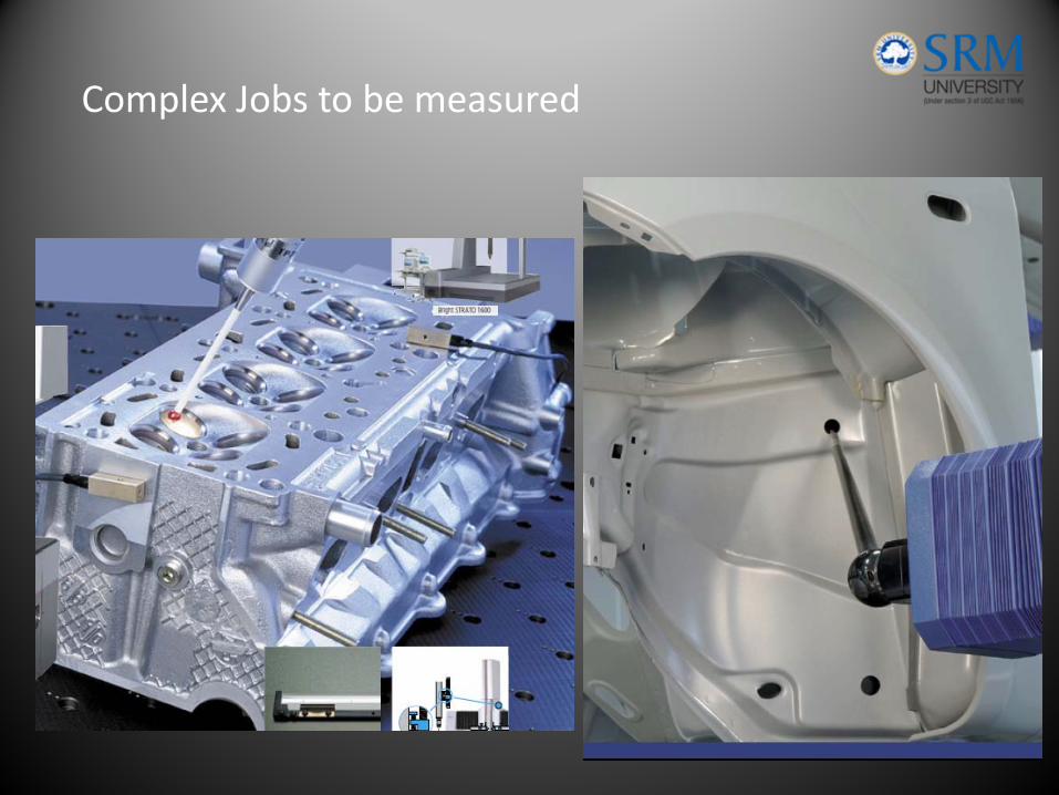
Complex Jobs to be measured
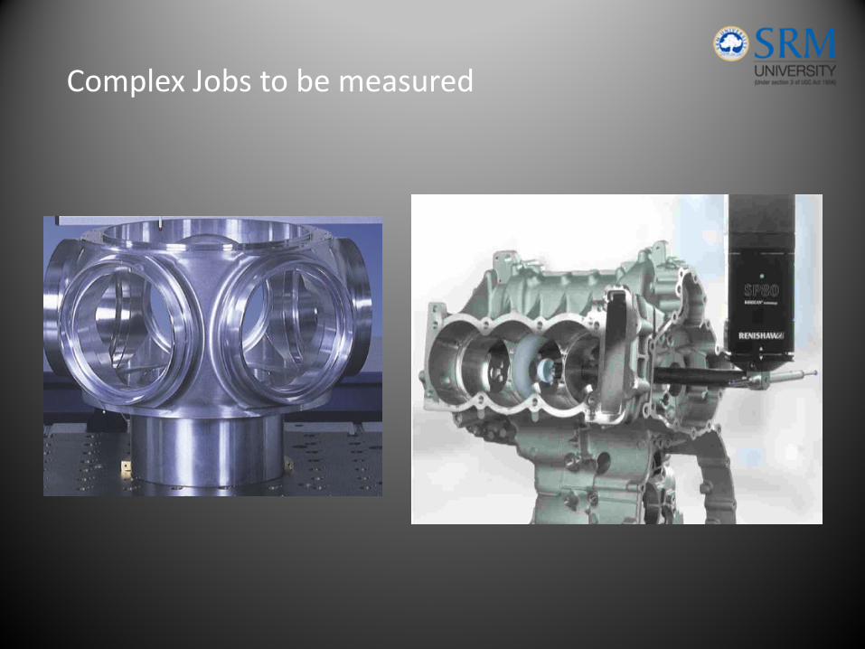
Complex Jobs to be measured
• To measure the actual size of w/p comparison with desired shape and evaluation of metrological information such as
• Size• Form• Location• Position
• Actual size is obtained by probing the surface at discrete measuring points. Every pt is expressed in terms of its x,y,z coordinates
Functions of CMM
• Mechanical Setup with 3 axes movement & the displacement transducer
• Probe head to probe the work piece in a spatial direction
• Control Unit
• Computer with software to calculate & represent the results
CMM system components
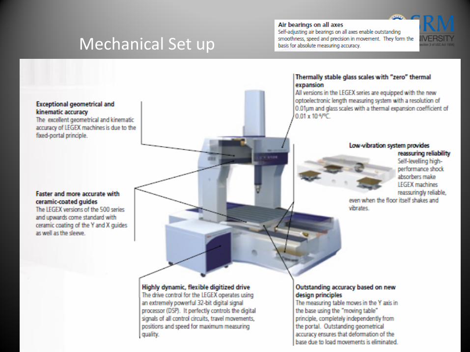
Mechanical Set up
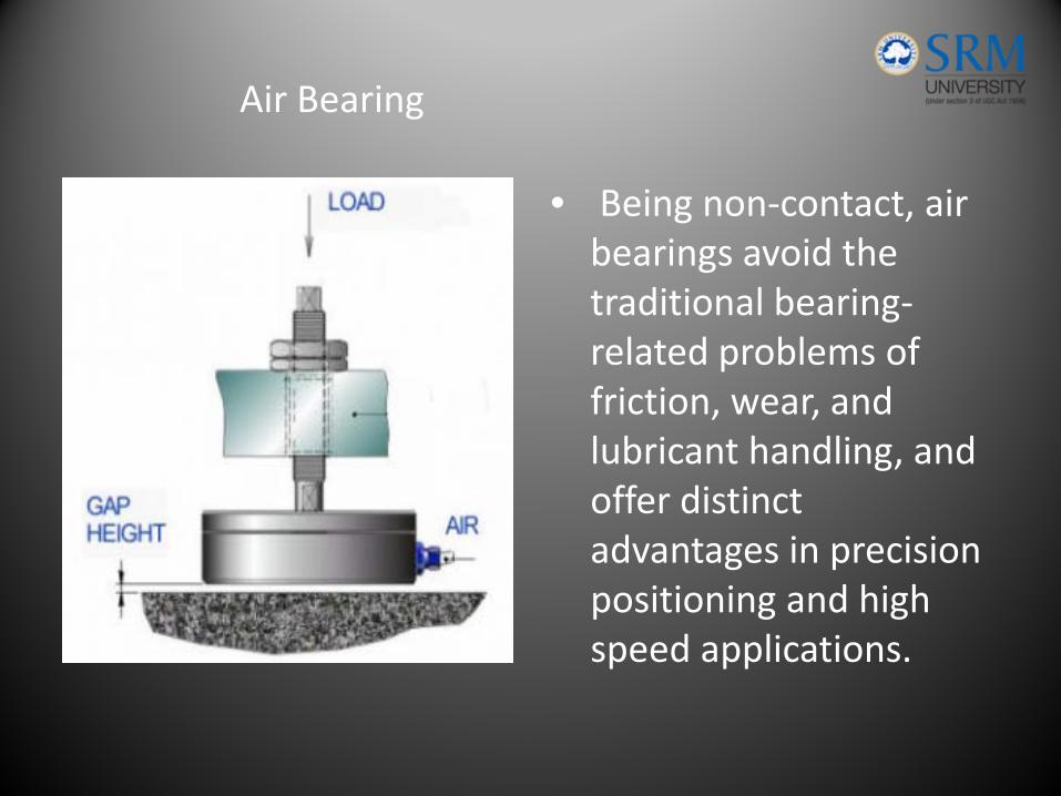
• Being non‐contact, air bearings avoid the traditional bearing‐related problems of friction, wear, and lubricant handling, and offer distinct advantages in precision positioning and high speed applications.
Air Bearing
• The fluid film of the bearing is achieved by supplying a flow of air through the bearing itself to the bearing surface.
• Numerous bearing designs exist to ensure uniform pressure is distributed across the entire bearing area.
• The design of the air bearing is such that, although the air constantly dissipates from the bearing site, the continual flow of pressurized air through the bearing is sufficient to support the working loads.
Air Bearing
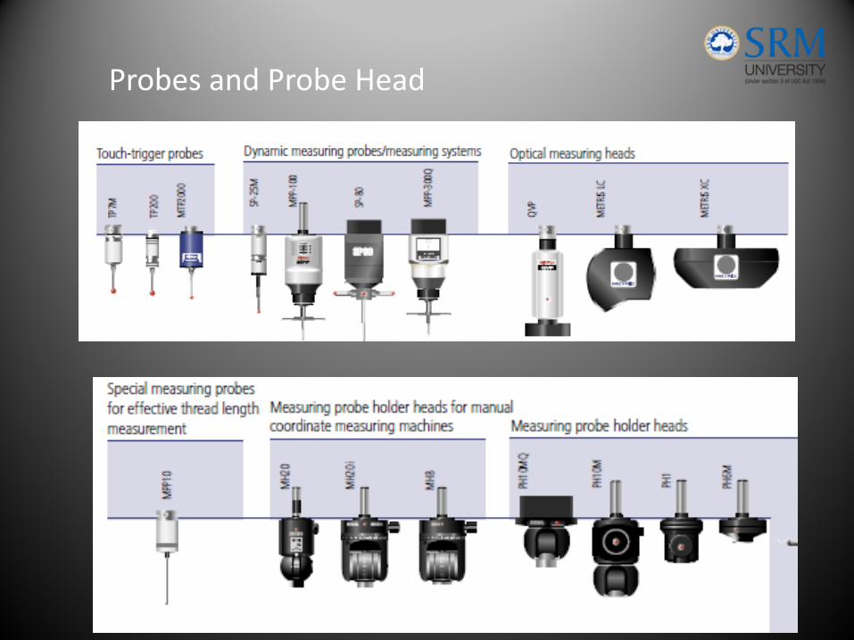
Probes and Probe Head
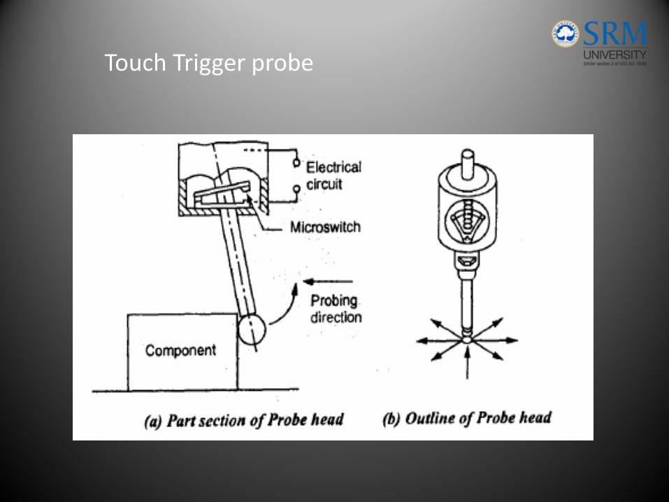
Touch Trigger probe
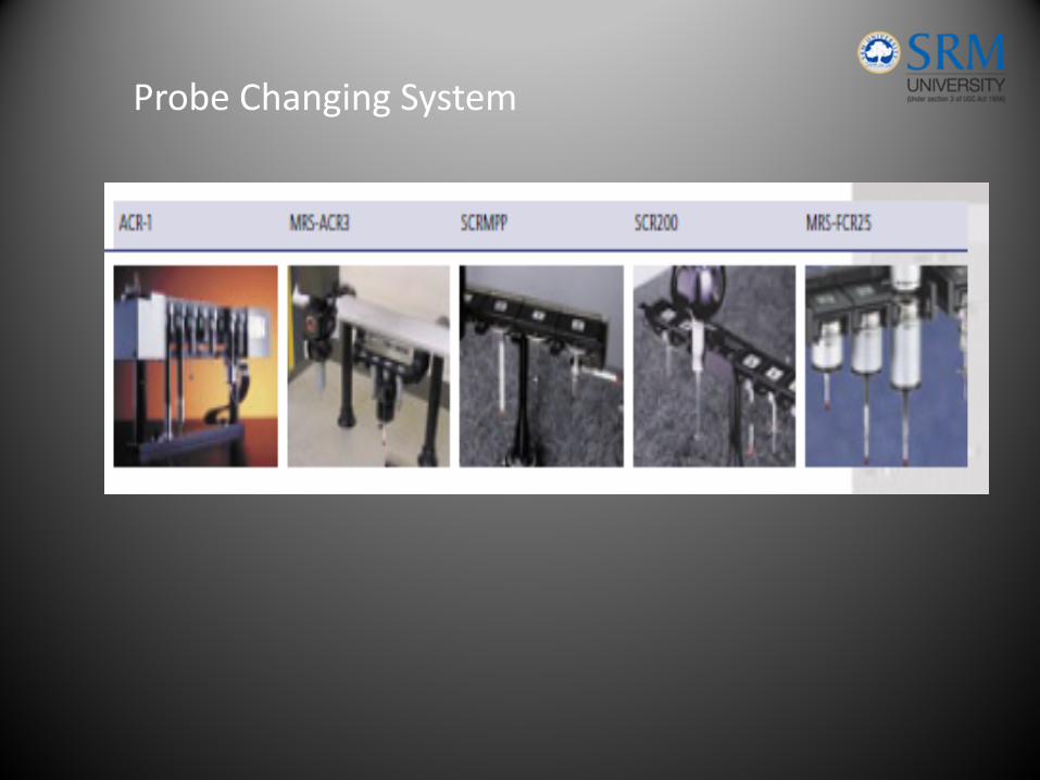
Probe Changing System
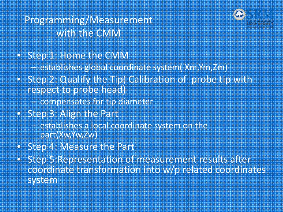
• Step 1: Home the CMM– establishes global coordinate system( Xm,Ym,Zm)
• Step 2: Qualify the Tip( Calibration of probe tip with respect to probe head)– compensates for tip diameter
• Step 3: Align the Part– establishes a local coordinate system on the part(Xw,Yw,Zw)
• Step 4: Measure the Part• Step 5:Representation of measurement results after coordinate transformation into w/p related coordinates system
Programming/Measurement with the CMM
• Moving bridge
• Fixed bridge
• Cantilever
• Gantry
Types of CMM
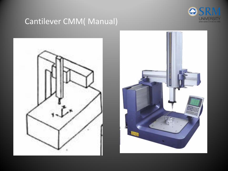
Cantilever CMM( Manual)
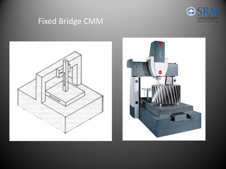
Fixed Bridge CMM
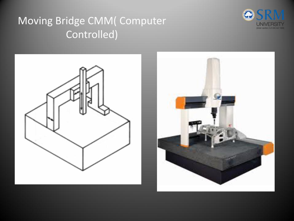
Moving Bridge CMM( Computer Controlled)
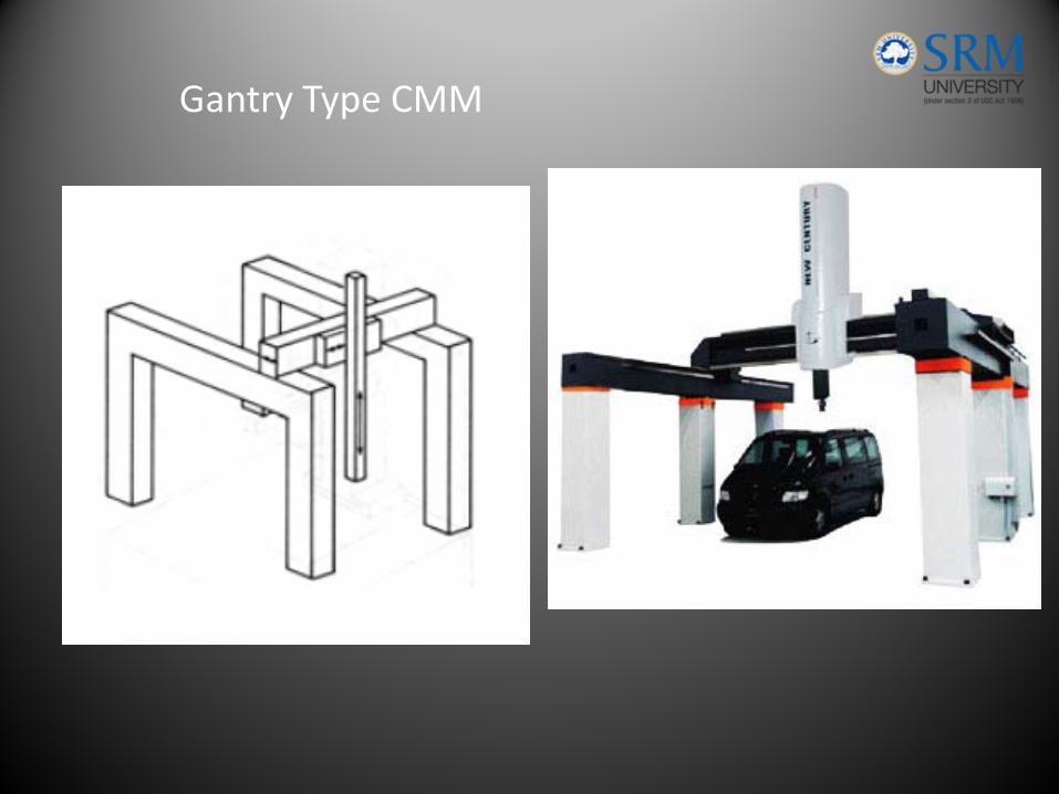
Gantry Type CMM
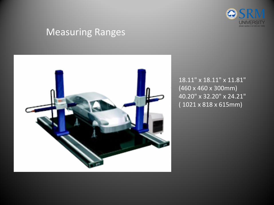
Measuring Ranges
18.11" x 18.11" x 11.81"(460 x 460 x 300mm) 40.20" x 32.20" x 24.21"( 1021 x 818 x 615mm)
• Sources of errors in CMM measurementsspatial errorscomputational errors.
Spatial errors are errors in the measured position of a point on the surface of the Work‐piece
• Computational errors are the errors in the estimated dimensions and form deviations of the work‐piece
Potential Sources of CMM Error
• The accuracy of the components of the CMM – the guide‐ways, the scales, the probe system and the qualification sphere.
• The environment in which the CMM operates – the ambient temperature, temperature gradients, humidity and vibration. •
• The probing strategy used – the magnitude and direction of the probe force, the type of probe stylus used and the measuring speed of the probe. •
• The characteristics of the work‐piece – elasticity, surface roughness, hardness and the mass of the component.
Spatial Errors
• The CMM software used to estimate the geometry of the work‐piece.
• The precision of the computer used on the CMM.
• The number and relative position of the measured points.
• The extent to which the geometry departs from the ideal geometric form.
Computational errors
Recommended