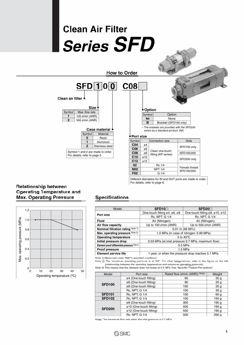
How to Order
Clean Air Filter
Series SFD
Specifications
Note 1) Measured under SMC’s specified conditions.Note 2) The maximum operating pressure is at 20C. For other temperatures, refer to the figure on the left
(relationship between the operating temperature and maximum operating pressure).Note 3) This means that the element does not break at 0.5 MPa. See “Specific Product Precautions”.
Port size
FluidAir flow capacityNominal filtration rating Note 1)
Max. operating pressure Note 2)
Operating temperatureInitial pressure dropElement proof differential pressure Note 3)
Proof pressureElement service life
One-touch fitting ø4, ø6, ø8Rc, NPT, G 1/4Air (Nitrogen)
Up to 100 l/min (ANR)0.01 m (99.99%)
1.0 MPa (in case of nitrogen: 0.99 MPa)5 to 45ºC
0.03 MPa (at inlet pressure 0.7 MPa, maximum flow)0.5 MPa1.5 MPa
1 year, or when the pressure drop reaches 0.1 MPa.
Model SFD10�One-touch fitting ø8, ø10, ø12
Rc, NPT, G 1/4Air (Nitrogen)
Up to 500 l/min (ANR)
SFD20�
SFD100
SFD101SFD102
SFD200
ø4 (One-touch fitting)ø6 (One-touch fitting)ø8 (One-touch fitting)Rc, NPT, G 1/4Rc, NPT, G 1/4Rc, NPT, G 1/4ø8 (One-touch fitting)ø10 (One-touch fitting)ø12 (One-touch fitting)Rc, NPT, G 1/4
6080
100100100100300400500500
35 g35 g35 g35 g60 g
150 g190 g190 g190 g260 g
Port sizeModel Rated flow (l/min (ANR)) Note) Weight
Note) The maximum flow rate when the inlet pressure is 0.7 MPa.
Relationship between Operating Temperature and Max. Operating Pressure
0 10 20 30 40 50
Operating temperature (ºC)
Max
. ope
ratin
g pr
essu
re (
MP
a)
1.2
1.0
0.8
0.6
0.4
0.2
0
1 0SFDClean air filter
0 C08
Symbol12
SizeMax. flow rate
100 l/min (ANR)500 l/min (ANR)
Symbol012
Case materialMaterialResin
AluminumStainless steel
Symbol 1 and 2 are made to order.For details, refer to page 5.
NilB
OptionOptionNone
Bracket (SFD100 only)
Symbol
∗ The brackets are provided with the SFD200 series as a standard product. (Nil)
C04C06C08C10C1202
N02F02
Port sizeConnection size Note
Rc 1/4NPT 1/4
G 1/4
ø4ø6ø8
ø10ø12
Clean one-touchfitting (KP series)
SFD100 only
SFD100/200
SFD200 only
Female threadSFD100/200
Symbol
Different diameters for IN and OUT ports are made to order.For details, refer to page 6.
1
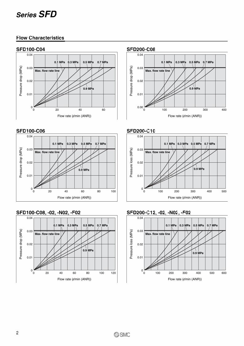
Flow Characteristics
SFD100-C04
0
0.01
0.02
0.03
0.04
0 20 40 60
Flow rate (l/min (ANR))
Pre
ssur
e dr
op (
MP
a)
0.9 MPa
0.1 MPa 0.3 MPa 0.5 MPa 0.7 MPa
Max. flow rate line
SFD100-C06
Flow rate (l/min (ANR))
Pre
ssur
e dr
op (
MP
a)
0
0.01
0.02
0.03
0.04
0 20 40 60 80 100
0.9 MPa
0.1 MPa 0.3 MPa 0.5 MPa 0.7 MPa
Max. flow rate line
SFD100-C08, -02, -N02, -F02
Flow rate (l/min (ANR))
Pre
ssur
e dr
op (
MP
a)
0
0.01
0.02
0.03
0.04
0 20 40 60 80 100 120
0.9 MPa
0.1 MPa 0.3 MPa 0.5 MPa 0.7 MPa
Max. flow rate line
SFD200-C08
Flow rate (l/min (ANR))
Pre
ssur
e dr
op (
MP
a)
0.00
0.01
0.02
0.03
0.04
0 100 200 300 400
0.9 MPa
0.1 MPa 0.3 MPa 0.5 MPa 0.7 MPa
Max. flow rate line
SFD200-C10
Flow rate (l/min (ANR))
Pre
ssur
e lo
ss (
MP
a)
0
0.01
0.02
0.03
0.04
0 100 200 300 400 500
0.9 MPa
0.1 MPa 0.3 MPa 0.5 MPa 0.7 MPa
Max. flow rate line
SFD200-C12, -02, -N02, -F02
Flow rate (l/min (ANR))
Pre
ssur
e lo
ss (
MP
a)
0
0.01
0.02
0.03
0.04
0 100 200 300 400 500 600
0.9 MPa
0.1 MPa 0.3 MPa 0.5 MPa 0.7 MPa
Max. flow rate line
2
Series SFD
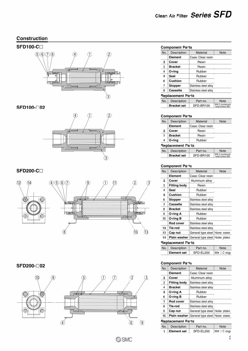
Construction
SFD100-C�
SFD100-�02
SFD200-C�
SFD200-�02
Replacement Parts
Element set
No. Description Note
1
Part no.
SFD-EL200 With 3 O-rings
Component Parts
Element
Cover
Fitting body
Seal
Cushion
Stopper
Cassette
Bracket
O-ring A
O-ring B
Rod cover
Tie-rod
Cap nut
Plain washer
No. Description Note
1
2
3
4
5
6
7
8
9
10
11
12
13
14
Material
Case: Clear resin
Aluminum alloy
Resin
Rubber
Rubber
Stainless steel alloy
Stainless steel alloy
Stainless steel alloy
Rubber
Rubber
Stainless steel alloy
Stainless steel alloy
General type steel
General type steel
Nickel plated
Nickel plated
Nickel plated
Nickel plated
Component Parts
Element
Cover
Fitting body
Bracket
O-ring A
O-ring B
Rod cover
Tie-rod
Cap nut
Plain washer
No. Description Note
1
2
3
4
5
6
7
8
9
10
Material
Case: Clear resin
Aluminum alloy
Stainless steel alloy
Stainless steel alloy
Rubber
Rubber
Stainless steel alloy
Stainless steel alloy
General type steel
General type steel
With 3 O-rings
Replacement Parts
Element set
No. Description Note
1
Part no.
SFD-EL200
tyui r q w
e
r q w
e
!2 !4
i
rtyu ewqo !1
!0 !3
i!0
r y o
wqt eu
Component Parts
Element
Cover
Bracket
O-ring
Seal
Cushion
Stopper
Cassette
No. Description Note
1
2
3
4
5
6
7
8
Material
Case: Clear resin
Resin
Resin
Rubber
Rubber
Rubber
Stainless steel alloy
Stainless steel alloy
Replacement Parts
Bracket set
No. Description Note
1
Part no.
SFD-BR100 With 2 countersunkhead screws (M3)
Component Parts
Element
Cover
Bracket
O-ring
No. Description Note
1
2
3
4
Material
Case: Clear resin
Resin
Resin
Rubber
Replacement Parts
Bracket set
No. Description Note
1
Part no.
SFD-BR100 With 2 countersunkhead screws (M3)
3
Clean Air Filter Series SFD
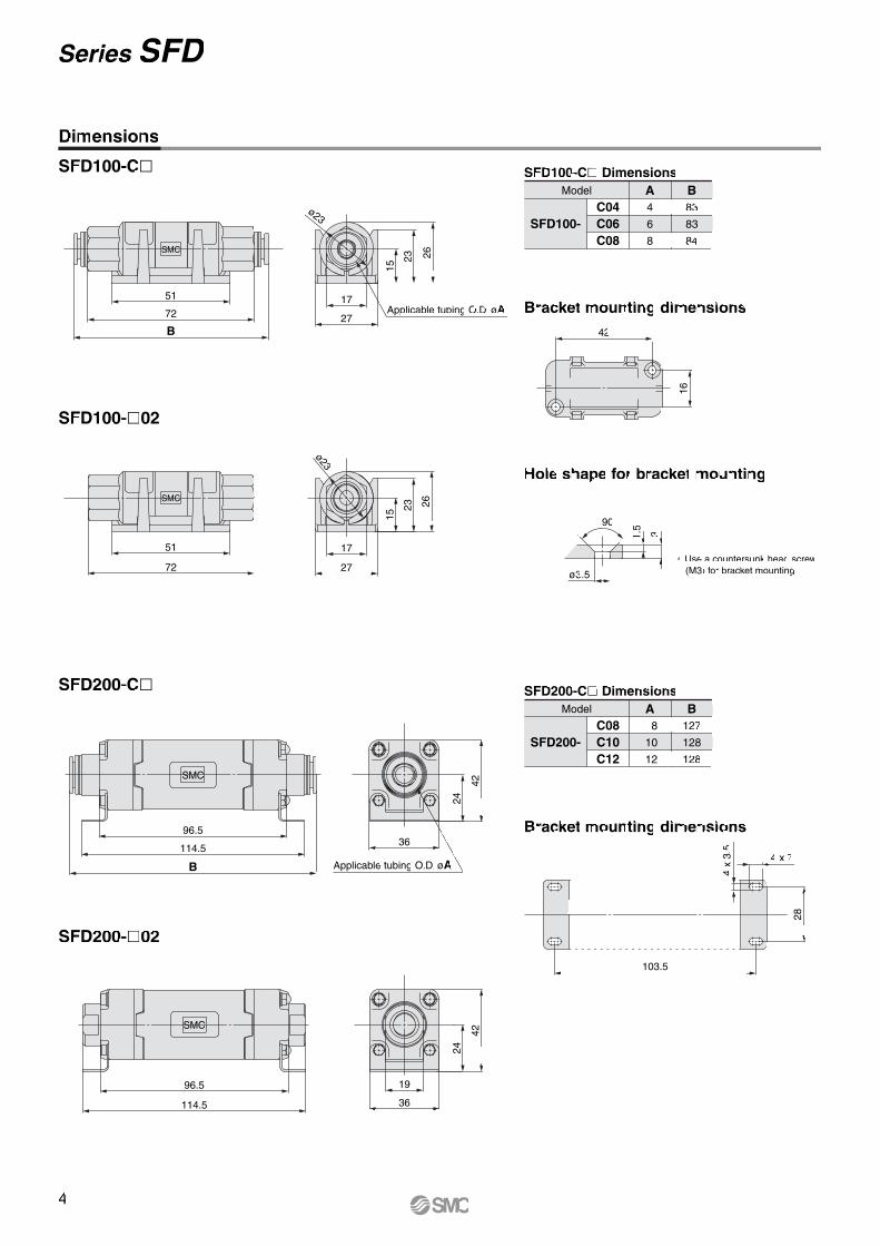
Dimensions
SFD100-C�
SFD100-�02
SFD200-C�
SFD200-�02
Bracket mounting dimensions
Hole shape for bracket mounting
Bracket mounting dimensions
SMC
51
72
15
23 26
27
17ø23
SMC
114.5
96.5
42
36
19
24
Model A83
83
84
4
6
8
B
SFD100-C04C06C08
SFD100-C� Dimensions
Model A127
128
128
8
10
12
B
SFD200-C08C10C12
SFD200-C� Dimensions
42
16
ø3.5
90
1.5
3
103.5
4 x 7
4 x
3.5
28
SMC
27
17
23 26
15
ø23
B
72
51Applicable tubing O.D. øA
SMC
96.5
114.5
B
36
24
42
Applicable tubing O.D. øA
∗ Use a countersunk head screw (M3) for bracket mounting.
4
Series SFD
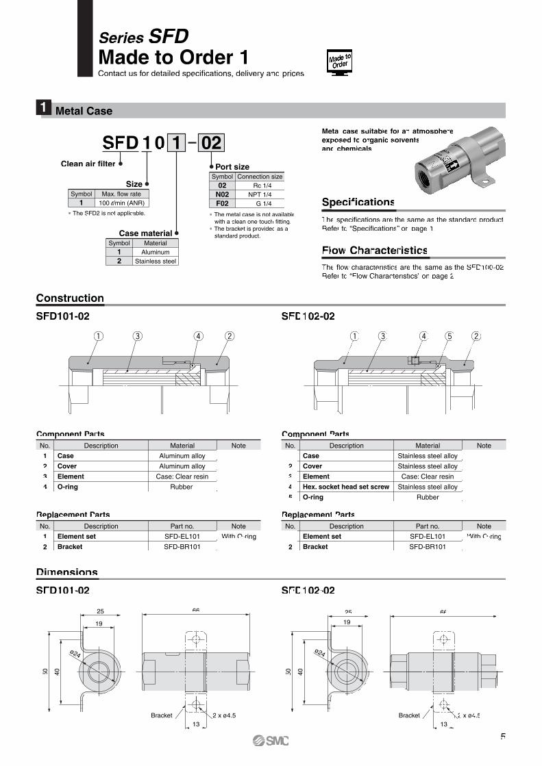
SFD101-02 SFD102-02
SFD101-02 SFD102-02
Component Parts
Case
Cover
Element
O-ring
No. Description Note
1
2
3
4
Material
Aluminum alloy
Aluminum alloy
Case: Clear resin
Rubber
Replacement Parts
Element set
Bracket
No. Description Note
1
2
Part no.
SFD-EL101
SFD-BR101
With O-ring
Component Parts
Case
Cover
Element
Hex. socket head set screw
O-ring
No. Description Note
1
2
3
4
5
Material
Stainless steel alloy
Stainless steel alloy
Case: Clear resin
Stainless steel alloy
Rubber
Replacement Parts
Element set
Bracket
No. Description Note
1
2
Part no.
SFD-EL101
SFD-BR101
With O-ring
Dimensions
Construction
Specifications
Series SFDMade to Order 1Contact us for detailed specifications, delivery and prices.
Metal Case1
25 66
132 x ø4.5
19
ø24
4050
Bracket
25 66
132 x ø4.5
19
ø24
4050
Bracket
wq r teq re w
The specifications are the same as the standard product.Refer to “Specifications” on page 1.
Flow CharacteristicsThe flow characteristics are the same as the SFD100-02.Refer to “Flow Characteristics” on page 2.
10SFDClean air filter
1 02
Symbol12
Case materialMaterial
AluminumStainless steel
Symbol1
SizeMax. flow rate
100 l/min (ANR)
∗ The SFD2 is not applicable.
02N02F02
Port sizeConnection size
Rc 1/4NPT 1/4
G 1/4
Symbol
∗ The metal case is not available with a clean one-touch fitting.
∗ The bracket is provided as a standard product.
Metal case suitable for an atmosphere exposed to organic solvents and chemicals
5
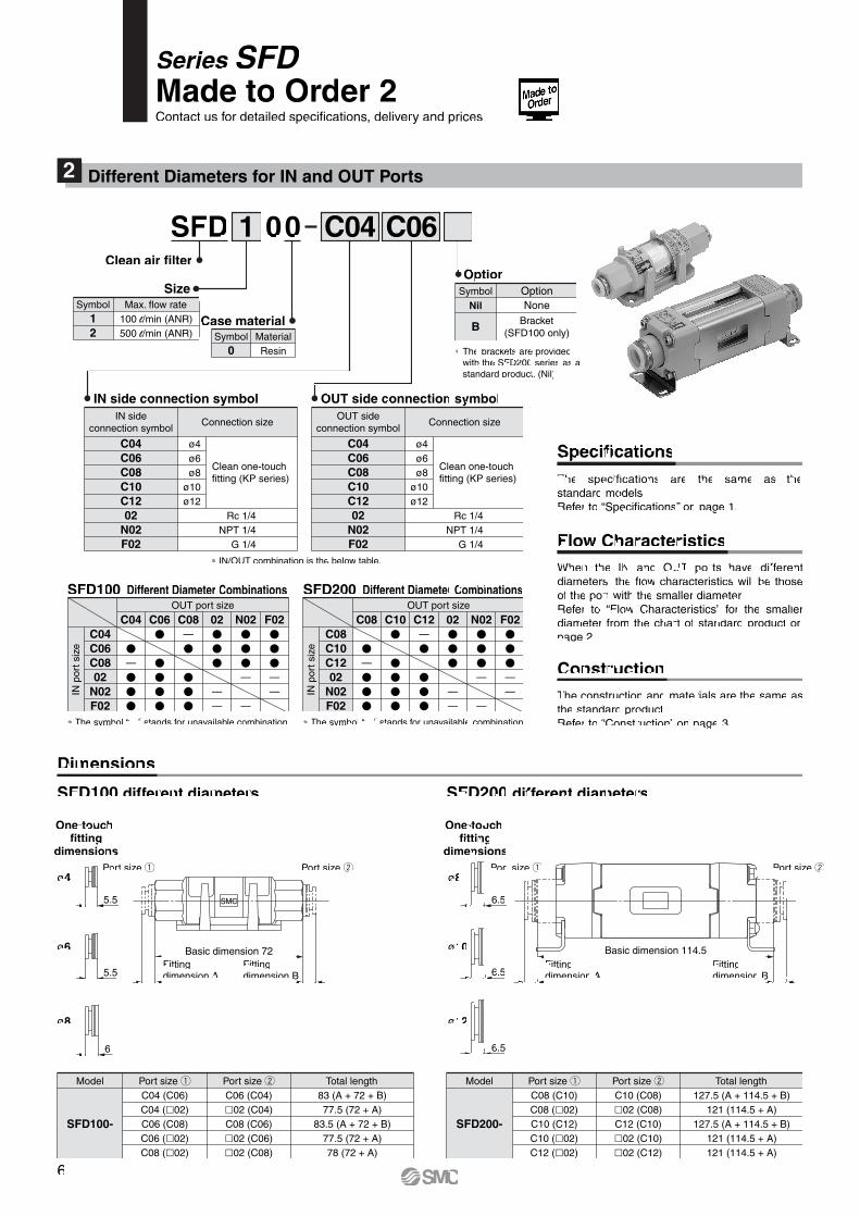
Different Diameters for IN and OUT Ports2
00SFDClean air filter
C041 C06
Symbol0
Case materialMaterialResin
Symbol12
SizeMax. flow rate
100 l/min (ANR)500 l/min (ANR)
∗ The brackets are provided with the SFD200 series as a standard product. (Nil)
Nil
B
OptionOptionNone
Bracket(SFD100 only)
Symbol
C04C06C08C10C1202
N02F02
IN side connection symbol
ø4ø6ø8
ø10ø12
Clean one-touchfitting (KP series)
Rc 1/4NPT 1/4
G 1/4
IN sideconnection symbol
Connection size
C04C06C08C10C1202
N02F02
OUT side connection symbol
ø4ø6ø8
ø10ø12
Clean one-touchfitting (KP series)
Rc 1/4NPT 1/4
G 1/4
OUT sideconnection symbol
Connection size
∗ IN/OUT combination is the below table.
SpecificationsThe specifications are the same as the standard models.Refer to “Specifications” on page 1.
Flow CharacteristicsWhen the IN and OUT ports have different diameters, the flow characteristics will be those of the port with the smaller diameter.Refer to “Flow Characteristics” for the smaller diameter from the chart of standard product on page 2.
ConstructionThe construction and materials are the same as the standard product.Refer to “Construction” on page 3.
Dimensions
SFD100 different diameters
C04C06C0802
N02F02
SFD100 Different Diameter CombinationsOUT port size
IN p
ort s
ize �
—���
C04�
����
C06—�
���
C08���
——
02���
—
—
N02���
——
F02
∗ The symbol “—” stands for unavailable combination.
IN p
ort s
ize
C08C10C1202
N02F02
SFD200 Different Diameter CombinationsOUT port size
�
—���
C08�
����
C10—�
���
C12���
——
02���
—
—
N02���
——
F02
∗ The symbol “—” stands for unavailable combination.
Model
SFD100-
Port size qC04 (C06)C04 (�02)C06 (C08)C06 (�02)C08 (�02)
Port size wC06 (C04)�02 (C04)C08 (C06)�02 (C06)�02 (C08)
Total length83 (A + 72 + B)77.5 (72 + A)
83.5 (A + 72 + B)77.5 (72 + A)78 (72 + A)
SFD200 different diameters
Model
SFD200-
Port size qC08 (C10)C08 (�02)C10 (C12)C10 (�02)C12 (�02)
Port size wC10 (C08)�02 (C08)C12 (C10)�02 (C10)�02 (C12)
Total length127.5 (A + 114.5 + B)
121 (114.5 + A)127.5 (A + 114.5 + B)
121 (114.5 + A)121 (114.5 + A)
ø12
6.5
ø10
6.5
ø8
6.5
One-touch fitting
dimensions
One-touch fitting
dimensions
ø8
ø6
ø4
5.5
5.5
6
Fitting dimension A
Basic dimension 114.5Fitting dimension B
Port size q Port size w
Fitting dimension A
Fitting dimension B
Port size q Port size w
SMC
Basic dimension 72
Series SFDMade to Order 2Contact us for detailed specifications, delivery and prices.
6
Recommended