4043240 Rev A
Cisco Prisma II Platform Installation & Configuration Guide
System Release 2.05.25


For Your Safety
Explanation of Warning and Caution Icons
Avoid personal injury and product damage! Do not proceed beyond any symbol until you fully understand the indicated conditions.
The following warning and caution icons alert you to important information about the safe operation of this product:
You may find this symbol in the document that accompanies this product. This symbol indicates important operating or maintenance instructions.
You may find this symbol affixed to the product. This symbol indicates a live terminal where a dangerous voltage may be present; the tip of the flash points to the terminal device.
You may find this symbol affixed to the product. This symbol indicates a protective ground terminal.
You may find this symbol affixed to the product. This symbol indicates a chassis terminal (normally used for equipotential bonding).
You may find this symbol affixed to the product. This symbol warns of a potentially hot surface.
You may find this symbol affixed to the product and in this document. This symbol indicates an infrared laser that transmits intensity-modulated light and emits invisible laser radiation or an LED that transmits intensity-modulated light.
Important
Please read this entire guide. If this guide provides installation or operation instructions, give particular attention to all safety statements included in this guide.

Notices
Trademark Acknowledgments
Cisco and the Cisco logo are trademarks or registered trademarks of Cisco and/or its affiliates in the U.S. and other countries. To view a list of Cisco trademarks, go to this URL: www.cisco.com/go/trademarks.
Third party trademarks mentioned are the property of their respective owners.
The use of the word partner does not imply a partnership relationship between Cisco and any other company. (1110R)
Publication Disclaimer
Cisco Systems, Inc. assumes no responsibility for errors or omissions that may appear in this publication. We reserve the right to change this publication at any time without notice. This document is not to be construed as conferring by implication, estoppel, or otherwise any license or right under any copyright or patent, whether or not the use of any information in this document employs an invention claimed in any existing or later issued patent.
Copyright
© 2012 Cisco and/or its affiliates. All rights reserved. Printed in the United States of America.
Information in this publication is subject to change without notice. No part of this publication may be reproduced or transmitted in any form, by photocopy, microfilm, xerography, or any other means, or incorporated into any information retrieval system, electronic or mechanical, for any purpose, without the express permission of Cisco Systems, Inc.

4043240 Rev A iii
Contents
Prisma II Product Notices xiii
Important Safety Instructions xv
Laser Safety xxv
Warning Labels ................................................................................................................. xxvii
Chapter 1 Quick Start Guide 1
Step 1: Install the Chassis in a Rack ....................................................................................... 2 To Install the Chassis in a Rack ................................................................................. 2
Step 2: Make Chassis-to-Chassis ICIM Connections ........................................................... 3 Chassis-to-Chassis ICIM Connections ..................................................................... 3 ICIM IN and ICIM OUT Connectors ........................................................................ 3 To Make ICIM IN and ICIM OUT Cable Connections .......................................... 3 ICIM IN and ICIM OUT Cables ................................................................................ 5
Step 3: Make Electrical Power Connections ......................................................................... 6 Electrical Power Connections .................................................................................... 6 Chassis Wiring and Fusing ........................................................................................ 6 DC Power Inlet Illustration ....................................................................................... 8 To Install the DC Power Cord ................................................................................. 10 To Install the AC Power Cord ................................................................................. 11 To Install the Power Supply in the Chassis ........................................................... 11
Step 4: Install the ICIM .......................................................................................................... 13 To Install the ICIM2 .................................................................................................. 13
Step 5: Set Network Parameters from the Command Line Interface (CLI) ................... 14 Step 6: Connect the ICIM to the Network .......................................................................... 18
To Set Up a Telnet CLI Session ............................................................................... 18 Step 7: Install Modules in the Chassis ................................................................................. 20
To Install the Module ............................................................................................... 20 Step 8: Set Additional Parameters via CLI (Optional) ..................................................... 22
To Set Additional Users for ICIM Access .............................................................. 22 Step 9: Set and Verify SNMP Community Strings ............................................................ 23 Step 10: Perform Chassis-to-Chassis ICIM Activation (Optional) .................................. 25 Step 11: Make Changes to Traps and Enterprise MIBs ..................................................... 26
MIB Software ............................................................................................................. 26 Trap Overview .......................................................................................................... 27

Contents
iv 4043240 Rev A
Step 12: Make Physical Connections to Modules .............................................................. 28 To Connect Optical Cables ...................................................................................... 28 To Connect RF Cables .............................................................................................. 28
Step 13: Verify System Release and Module Firmware Versions ................................... 29 Step 14: Install and Use the Firmware Update (SOUP) Utility (Optional) .................... 30
To Install the SOUP on Windows ........................................................................... 30 To Use the SOUP Utility .......................................................................................... 30 To Uninstall the SOUP on Windows ...................................................................... 31
Chapter 2 Introduction 33
Related Publications .............................................................................................................. 35 Prisma II Platform Description ............................................................................................ 36
Prisma II Platform Components ............................................................................. 36 Prisma II Fan Tray .................................................................................................... 37 Prisma II Power Supplies ......................................................................................... 37 ICIM2 .......................................................................................................................... 37 Prisma II Application Modules ............................................................................... 38
Prisma II Chassis .................................................................................................................... 39 Chassis Configuration .............................................................................................. 39 Typical Chassis Block Diagram .............................................................................. 40 Front-Access Chassis ................................................................................................ 41 Chassis Front Panel Features ................................................................................... 42 Chassis Back Plane Bus ............................................................................................ 43 Prisma II Power Supplies ......................................................................................... 43 Back Plane Bus Connectors ..................................................................................... 44
Prisma II Fan Tray.................................................................................................................. 45 Fan Tray Configuration ............................................................................................ 45 ICIM2 Block Diagram ............................................................................................... 45 Fan Tray Installation ................................................................................................. 45 Fan Tray Illustration (Top View) ............................................................................ 46 Fan Tray Front Panel Features ................................................................................ 46
Prisma II Power Supply ........................................................................................................ 47 Electrical Input Voltages .......................................................................................... 47 Power Inlets ............................................................................................................... 47 Power Supply Block Diagram ................................................................................. 48 Power Supply Front Panel Illustrations ................................................................. 49 Power Supply Front Panel Features ....................................................................... 49
Prisma II ICIM2 ...................................................................................................................... 50 ICIM2 Illustration (Front Panel) ............................................................................. 51 ICIM2 Front Panel Features ..................................................................................... 51
Module Back Panel ................................................................................................................ 52 Back Panel Connectors ............................................................................................. 52 Power and Communications Connector ............................................................... 52

Contents
4043240 Rev A v
Chapter 3 Hardware Installation 53
Before You Begin .................................................................................................................... 54 Unpacking and Inspecting the Chassis .................................................................. 54 Required Equipment and Tools .............................................................................. 54
Site Requirements .................................................................................................................. 55 Operating Environment ........................................................................................... 55 Chassis Wiring and Fusing ...................................................................................... 55 Rack Location Requirements ................................................................................... 57 Unused Slots .............................................................................................................. 57
Mounting the Chassis in a Rack ........................................................................................... 58 To Install the Chassis in a Rack ............................................................................... 58 Chassis Dimensions .................................................................................................. 59
Connector Interface Panel ..................................................................................................... 60 Connector Interface Panel Illustration ................................................................... 60
Connecting the ICIM to Additional Chassis ...................................................................... 62 To Make ICIM IN and ICIM OUT Cable Connections ........................................ 62 ICIM IN and ICIM OUT Connectors ...................................................................... 64 ICIM IN and ICIM OUT Cables .............................................................................. 64 Chassis-to-Chassis ICIM2 Activation ..................................................................... 64
External Alarms Connections ............................................................................................... 66 Master-Slave Operation ........................................................................................... 66 ALARM IN and OUT Connections ........................................................................ 66 Master-Slave Illustration .......................................................................................... 67 ALARMS IN Connector ........................................................................................... 67 ALARMS OUT Connector ....................................................................................... 67
Fan Tray ................................................................................................................................... 68 To Remove the Fan Tray .......................................................................................... 68
Chassis Fan Filter ................................................................................................................... 69 To Remove Chassis Fan Filter ................................................................................. 70
Installing the Power Supplies............................................................................................... 71 Space Requirements.................................................................................................. 71 Electrical Power Connections .................................................................................. 71 To Install the AC Power Cord ................................................................................. 73 To Install the DC Power Cord ................................................................................. 73 To Install the Power Supply in the Chassis ........................................................... 74 Power Supply Cooling Fans .................................................................................... 75 To Monitor the Power Supply ................................................................................. 75
Installing the ICIM2 ............................................................................................................... 76 To Install the ICIM2 .................................................................................................. 76
Installing the Module in the Chassis ................................................................................... 78 To Install the Module ............................................................................................... 78
Cleaning Optical Connectors ............................................................................................... 81 Recommended Equipment ...................................................................................... 81 Tips for Optimal Fiber Optic Connector Performance ........................................ 81 To Clean Optical Connectors .................................................................................. 82

Contents
vi 4043240 Rev A
Connecting Optical Cables ................................................................................................... 83 To Connect Optical Cables ...................................................................................... 83
Connecting RF Cables ........................................................................................................... 84 To Connect RF Cables .............................................................................................. 84
Chapter 4 Equipment Configuration 85
HyperTerminal Session Setup .............................................................................................. 86 To Set Up a HyperTerminal Serial Port Session ................................................... 86
CLI Parameters ....................................................................................................................... 90 Login ........................................................................................................................... 90 To Set the Clock ......................................................................................................... 91 To Set Additional Users for ICIM Access .............................................................. 91 To Set and Verify SNMP Community Strings ...................................................... 92
Telnet Session ......................................................................................................................... 94 To Set Up a Telnet CLI Session ............................................................................... 94
SNMP Parameters .................................................................................................................. 96 Using the ICIM Web Interface ............................................................................................. 97
Login Settings ............................................................................................................ 97 To Log In .................................................................................................................... 98 To Log Out ................................................................................................................. 99
Chapter 5 ICIM Operation 101
Platform Configuration ....................................................................................................... 102 Operating the ICIM2............................................................................................................ 103
ICIM2 Illustration (Front Panel) ........................................................................... 103 ICIM2 Front Panel Features ................................................................................... 104 ICIM2 LCD ............................................................................................................... 104 ICIM2 Keypad ......................................................................................................... 105 To Adjust the ICIM2 LCD Contrast ..................................................................... 105 ICIM Password ........................................................................................................ 106 Prisma II MAIN Menu and ICIM Menu Structure ............................................. 110
Configuring for Remote Network Access ........................................................................ 113 Preliminary Steps for SNMP ................................................................................. 113 To Configure the ICIM2 for SNMP ...................................................................... 113 To Restart the ICIM2 .............................................................................................. 115
Using ICIM2 with the Fan Tray ......................................................................................... 116 Fan Tray Menu Structure ....................................................................................... 116 To Check Operating Status .................................................................................... 116 Fan Tray STATUS Menus ...................................................................................... 117 To Check Alarms ..................................................................................................... 117 Fan Tray ALARMS Menus .................................................................................... 118 To Check Fan Tray Manufacturing Data ............................................................. 119 Fan Tray MFG. DATA Menus ............................................................................... 120

Contents
4043240 Rev A vii
Using ICIM2 with Power Supply 1 ................................................................................... 121 Power Supply 1 Menu Structure........................................................................... 121 To Check Operating Status .................................................................................... 121 Power Supply 1 STATUS Menus .......................................................................... 122 To Check Alarms ..................................................................................................... 122 Power Supply 1 ALARMS Menus ........................................................................ 123 To Check Power Supply 1 Manufacturing Data ................................................. 124 Power Supply 1 MFG. DATA Menus .................................................................. 125
Using ICIM2 with Power Supply 3 ................................................................................... 126 Power Supply 3 Menu Structure........................................................................... 126 To Check Operating Status .................................................................................... 126 Power Supply 3 STATUS Menus .......................................................................... 127 To Check Alarms ..................................................................................................... 127 Power Supply 3 ALARMS Menus ........................................................................ 128 To Check Power Supply 3 Manufacturing Data ................................................. 129 Power Supply 3 MFG. DATA Menus .................................................................. 130 ICIM Password (Keypad Interface) ...................................................................... 130 Configuring a Module using the ICIM ................................................................ 135 Checking Alarms using the ICIM ......................................................................... 136
Chapter 6 LCI Operation 141
LCI Introduction .................................................................................................................. 142 System Requirements .......................................................................................................... 143
Computer Requirements ........................................................................................ 143 Cable Requirements ................................................................................................ 143
Installing LCI ........................................................................................................................ 144 To Install the LCI Software .................................................................................... 144
Connecting Your Computer to the Chassis ...................................................................... 148 To Connect the Computer to a Prisma II Chassis............................................... 148
Starting LCI Software .......................................................................................................... 149 To Start LCI Software ............................................................................................. 149
LCI Module Tree .................................................................................................................. 151 Module Tree ............................................................................................................. 151
Accessing the Module Detail Information ....................................................................... 152 Sample Module Details Window .......................................................................... 152
Checking the Operating Status .......................................................................................... 153 To Check the Operating Status using LCI ........................................................... 153
Checking the Module Alarms using LCI .......................................................................... 154 To Check Alarms using LCI .................................................................................. 154
Modifying Module Alarm Limits using LCI .................................................................... 156 To Modify Alarm Limits using LCI ...................................................................... 156
Checking Manufacturing Data using LCI ........................................................................ 158 To Check Manufacturing Data using LCI ........................................................... 158

Contents
viii 4043240 Rev A
Chapter 7 User Management 159
Introduction .......................................................................................................................... 160 User Accounts ......................................................................................................... 160 Usernames ................................................................................................................ 160 Passwords ................................................................................................................ 161 Security Levels ........................................................................................................ 161 Account Enable or Disable .................................................................................... 161 Login Thresholds .................................................................................................... 162 User Lockout............................................................................................................ 162 Inactivity Timeout................................................................................................... 162
Replacing the Default Admin Account ............................................................................. 163 To Replace the Default Admin Account .............................................................. 163
Working With User Accounts ............................................................................................ 167 To Add a New User ................................................................................................ 167 To Change a User Password.................................................................................. 168 To Change a User Security Level .......................................................................... 169 To Change User Account Status ........................................................................... 171 To Unlock User Accounts ...................................................................................... 172 To Delete a User Account ...................................................................................... 172 To List All Currently Logged In Users ................................................................ 173
User Lockout ......................................................................................................................... 174 To View the Current Lockout Interval ................................................................. 174 To Specify a New Lockout Interval ...................................................................... 175 To View Locked-Out Users ................................................................................... 176 To View Lockout Time Remaining by User ........................................................ 177 To Unlock a Locked-Out User ............................................................................... 178
Chapter 8 Event Log 179
Introduction .......................................................................................................................... 180 Event Log Fields ...................................................................................................... 180 Event Action IDs ..................................................................................................... 181
Viewing the Event Log ........................................................................................................ 184 To View the Event Log through the CLI ............................................................. 184 To View the Event Log through the Web Interface ........................................... 185
Clearing the Event Log ........................................................................................................ 186 To Clear the Event Log through the CLI ............................................................. 186 To Clear the Event Log through the Web Interface ........................................... 186
Setting Event Log Filter Parameters .................................................................................. 187 To View Filter Parameters through the CLI ........................................................ 187 To Set Filter Parameters through the CLI ............................................................ 187 To View Filter Parameters through the Web Interface ...................................... 188 To Set Filter Parameters through the Web Interface .......................................... 188

Contents
4043240 Rev A ix
Event Log-Related Traps .................................................................................................... 189 Example: 80% Full Trap ......................................................................................... 189 Example: 100% Full Trap ....................................................................................... 190
Downloading and Viewing the Event Log Remotely ..................................................... 191 To Download the Event Log File .......................................................................... 191
Chapter 9 SNMP Management 193
Introduction .......................................................................................................................... 194 Prisma II Enterprise MIBs ...................................................................................... 194
ICIM MIB .............................................................................................................................. 195 To View the ICIM MIB ........................................................................................... 195 ICIM MIB Elements ................................................................................................ 195 Event Log File Management.................................................................................. 209 SNTP Time Synchronization ................................................................................. 213 Trap Handling ......................................................................................................... 216 Trap Recv Table ....................................................................................................... 216 Trap Logging Auxiliaries ....................................................................................... 220 Trap Logging Table ................................................................................................ 221
Module MIB .......................................................................................................................... 226 Module MIB Tables ................................................................................................ 226 Module Table ........................................................................................................... 227 Module Alarm Table .............................................................................................. 235 Alarm Severity Mappings ...................................................................................... 241 Current Alarm Table .............................................................................................. 242 Module Monitor Table ........................................................................................... 244 Module Control Table ............................................................................................ 247 Insert Module Table ................................................................................................ 250 Remove Module Table ........................................................................................... 251
Remote Reboot of ICIM and Modules .............................................................................. 253 To Reboot the ICIM via SNMP ............................................................................. 253 To Reboot a Module via SNMP ............................................................................ 253
Prisma II Traps ..................................................................................................................... 254 About Traps ............................................................................................................. 254 Trap Receiving Configuration ............................................................................... 255 To Configure Trap Destination ............................................................................. 256 Trap Types ............................................................................................................... 257 Enhanced Trap Binding Information ................................................................... 268 Enhanced Trap Alarms .......................................................................................... 272 Enhanced Trap Events ........................................................................................... 275
Alarm Threshold Modification .......................................................................................... 293 System Behavior ................................................................................................................... 295
ICIM as Proxy for Module Information ............................................................... 295 Delay in the Discovery Process ............................................................................. 295 Module Removal and Enhanced Traps ............................................................... 295
Frequently Asked Questions .............................................................................................. 296 How do I configure trap destination? .................................................................. 296
Contents
x 4043240 Rev A
Why do the same alarm values represent different conditions? ...................... 296 How do Enhanced Traps differ from other trap types? .................................... 297 When do traps associated with module insertion, removal, and alarms
occur? ..................................................................................................................... 297 Where can I find trap definitions? ........................................................................ 298 What is the Trap Logging Table? .......................................................................... 298
Chapter 10 Remote Firmware Download Feature 299
Installing the SOUP ............................................................................................................. 300 To Install the SOUP on Windows ......................................................................... 300 To Uninstall the SOUP on Windows .................................................................... 300
Concepts ................................................................................................................................ 301 The Chassis and the ICIM2 .................................................................................... 301 Release Files ............................................................................................................. 301 Active and Inactive Flash ....................................................................................... 301 Concurrency ............................................................................................................ 302 Integration with an NMS (Optional) .................................................................... 302
Usage ..................................................................................................................................... 303 Launching Standalone (Windows Only) ............................................................. 303 SOUP Main Screen .................................................................................................. 305 Firmware Upgrade Process ................................................................................... 307 FTP Settings ............................................................................................................. 309 SNMP Settings ......................................................................................................... 310 FTP Server ................................................................................................................ 311
Firmware Updates ............................................................................................................... 312
Chapter 11 Setting Up IPsec 315
IPsec Overview ..................................................................................................................... 316 Key Exchange .......................................................................................................... 316 IPsec Packets ............................................................................................................ 316
Configuring IPsec on the ICIM .......................................................................................... 318 To Enable and Disable IPsec .................................................................................. 318 To Add or Delete an IPsec Peer ............................................................................ 319 To Display IPsec Information ................................................................................ 320
Configuring IPsec on Windows ......................................................................................... 321 To Access the IPsec Management Console .......................................................... 321 To Create a New IP List ......................................................................................... 327 To Create a New Filter Action .............................................................................. 330 To Create a New IPsec Policy ................................................................................ 335
Configuring IPsec on Solaris .............................................................................................. 344 Solaris Configuration Files .................................................................................... 344 To Configure IPsec on Solaris ............................................................................... 348 References ................................................................................................................ 348

Contents
4043240 Rev A xi
Chapter 12 Maintenance and Troubleshooting 349
Maintenance.......................................................................................................................... 351 Maintenance Record ............................................................................................... 351
Troubleshooting ................................................................................................................... 352 Chassis Troubleshooting ........................................................................................ 352 Alarm Troubleshooting .......................................................................................... 353
FansOk Alarm ...................................................................................................................... 354 FansOk Alarm Parameters .................................................................................... 354 Suggested Actions ................................................................................................... 354
ChasTemp Alarm ................................................................................................................. 355 ChasTemp Alarm Parameters ............................................................................... 355 Suggested Actions ................................................................................................... 355
Ps1PwrIn Alarm ................................................................................................................... 357 Ps1PwrIn Alarm Parameters ................................................................................. 357 Suggested Actions ................................................................................................... 357
Ps1+24 Alarm ....................................................................................................................... 358 Ps1+24 Alarm Parameters ...................................................................................... 358 Suggested Actions ................................................................................................... 358
Ps1+5VDC Alarm ................................................................................................................. 359 Ps1+5VDC Alarm Parameters ............................................................................... 359 Suggested Actions ................................................................................................... 359
Ps1-5VDC Alarm .................................................................................................................. 360 PS1-5VDC Alarm Parameters ............................................................................... 360 Suggested Actions ................................................................................................... 360
Ps3PwrIn Alarm ................................................................................................................... 361 Ps3PwrIn Alarm Parameters ................................................................................. 361 Suggested Actions ................................................................................................... 361
Ps3+24 Alarm ....................................................................................................................... 362 Ps3+24 Alarm Parameters ...................................................................................... 362 Suggested Actions ................................................................................................... 362
Ps3+5VDC Alarm ................................................................................................................. 363 Ps3+5VDC Alarm Parameters ............................................................................... 363 Suggested Actions ................................................................................................... 363
Ps3-5VDC Alarm .................................................................................................................. 364 PS3-5VDC Alarm Parameters ............................................................................... 364 Suggested Actions ................................................................................................... 364
Cleaning Optical Connectors ............................................................................................. 365 Recommended Equipment .................................................................................... 365 Tips for Optimal Fiber Optic Connector Performance ...................................... 365 To Clean Optical Connectors ................................................................................ 366
Connecting Optical Cables ................................................................................................. 367 To Connect Optical Cables .................................................................................... 367

Contents
xii 4043240 Rev A
Chapter 13 Customer Information 369
Appendix A Prisma II Permitted CLI Commands 371
From CLI ............................................................................................................................... 372 From ICIM............................................................................................................................. 373 From */* MODULE ............................................................................................................. 379 From TERMINAL ................................................................................................................ 382
Appendix B Features Available via Remote User Interface 383
Overview ............................................................................................................................... 384 ICIM Data .............................................................................................................................. 385 Module Data ......................................................................................................................... 388 Current Alarms .................................................................................................................... 389 Module Alarms .................................................................................................................... 390 Module Controls .................................................................................................................. 391 Module Monitors ................................................................................................................. 392 System Information ............................................................................................................. 393 User Management ................................................................................................................ 394
Appendix C Module Parameter Descriptions 395
Prisma II Chassis Parameters ............................................................................................. 396 Prisma II Chassis Configurable Parameters ........................................................ 396 Prisma II Chassis Alarm Data Parameters .......................................................... 396 Prisma II Chassis Operating Status Parameters ................................................. 397 Prisma II Chassis Manufacturing Data Parameters ........................................... 398
Glossary 399
Index 405

Prisma II Product Notices
4043240 Rev A xiii
Prisma II Product Notices
System Release
The information in this guide pertains to System Release 2.05.25 of the Prisma II Platform.
Operating Temperature
CAUTION:
The warranty may be voided and the equipment damaged if you operate the equipment above the specified temperature limits (131°F/55°C for post-amplifiers, 149°F/65°C for other products). Specification temperature limits are measured in the air stream at the fan tray inlet and may be higher than room ambient temperature.
CAUTION:
Do not operate post-amplifiers at air inlet temperature above 30°C for extended periods or repetitively. Extended or repetitive operation above 30°C will reduce amplifier useful life and increase amplifier failure rate.


Important Safety Instructions
4043240 Rev A xv
Important Safety Instructions
Read and Retain Instructions
Carefully read all safety and operating instructions before operating this equipment, and retain them for future reference.
Follow Instructions and Heed Warnings
Follow all operating and use instructions. Pay attention to all warnings and cautions in the operating instructions, as well as those that are affixed to this equipment.
Terminology
The terms defined below are used in this document. The definitions given are based on those found in safety standards.
Service Personnel - The term service personnel applies to trained and qualified individuals who are allowed to install, replace, or service electrical equipment. The service personnel are expected to use their experience and technical skills to avoid possible injury to themselves and others due to hazards that exist in service and restricted access areas.
User and Operator - The terms user and operator apply to persons other than service personnel.
Ground(ing) and Earth(ing) - The terms ground(ing) and earth(ing) are synonymous. This document uses ground(ing) for clarity, but it can be interpreted as having the same meaning as earth(ing).
Electric Shock Hazard
This equipment meets applicable safety standards.
WARNING:
To reduce risk of electric shock, perform only the instructions that are included in the operating instructions. Refer all servicing to qualified service personnel only.
Electric shock can cause personal injury or even death. Avoid direct contact with dangerous voltages at all times. The protective ground connection, where provided, is essential to safe operation and must be verified before connecting the power supply.

Important Safety Instructions
xvi 4043240 Rev A
Know the following safety warnings and guidelines:
Dangerous Voltages
- Only qualified service personnel are allowed to perform equipment installation or replacement.
- Only qualified service personnel are allowed to remove chassis covers and access any of the components inside the chassis.
Grounding
- Prisma II equipment is suitable for installation as part of the common bonding network (CBN).
- Do not violate the protective grounding by using an extension cable, power cable, or autotransformer without a protective ground conductor.
- Take care to maintain the protective grounding of this equipment during service or repair and to re-establish the protective grounding before putting this equipment back into operation.
Note: See the Installation section of this document for specific information regarding the AC and DC power, wiring, fusing, and grounding requirements for this product.
Installation Site
When selecting the installation site, comply with the following:
Protective Ground - The protective ground lead of the building’s electrical installation should comply with national and local requirements.
Environmental Condition – The installation site should be dry, clean, and ventilated. Do not use this equipment where it could be at risk of contact with water. Ensure that this equipment is operated in an environment that meets the requirements as stated in this equipment’s technical specifications, which may be found on this equipment’s data sheet.
Installation Requirements
WARNING:
Allow only qualified service personnel to install this equipment. The installation must conform to all local codes and regulations.
Equipment Placement
WARNING:
Avoid personal injury and damage to this equipment. An unstable mounting surface may cause this equipment to fall.

Important Safety Instructions
4043240 Rev A xvii
Prisma II equipment is suitable for installation in network telecommunications facilities.
To protect against equipment damage or injury to personnel, comply with the following:
Install this equipment in a restricted access location.
Do not install near any heat sources such as radiators, heat registers, stoves, or other equipment (including amplifiers) that produce heat.
Place this equipment close enough to a DC input voltage source to accommodate the length of this equipment’s power cord.
Route all power cords so that people cannot walk on, place objects on, or lean objects against them. This may pinch or damage the power cords. Pay particular attention to power cords at plugs, outlets, and the points where the power cords exit this equipment.
Use only with a cart, stand, tripod, bracket, or table specified by the manufacturer, or sold with this equipment.
Make sure the mounting surface or rack is stable and can support the size and weight of this equipment.
The mounting surface or rack should be appropriately anchored according to manufacturer’s specifications. Ensure this equipment is securely fastened to the mounting surface or rack where necessary to protect against damage due to any disturbance and subsequent fall.
Ventilation
This equipment has openings for ventilation to protect it from overheating. To ensure equipment reliability and safe operation, do not block or cover any of the ventilation openings. Install the equipment in accordance with the manufacturer’s instructions.
Rack Mounting Safety Precautions
Mechanical Loading
Make sure that the rack is placed on a stable surface. If the rack has stabilizing devices, install these stabilizing devices before mounting any equipment in the rack.
WARNING:
Avoid personal injury and damage to this equipment. Mounting this equipment in the rack should be such that a hazardous condition is not caused due to uneven mechanical loading.

Important Safety Instructions
xviii 4043240 Rev A
Reduced Airflow
When mounting this equipment in the rack, do not obstruct the cooling airflow through the rack. Be sure to mount the blanking plates to cover unused rack space. Additional components such as combiners and net strips should be mounted at the back of the rack, so that the free airflow is not restricted.
CAUTION:
Installation of this equipment in a rack should be such that the amount of airflow required for safe operation of this equipment is not compromised.
Elevated Operating Ambient Temperature
Only install this equipment in a humidity- and temperature-controlled environment that meets the requirements given in this equipment’s technical specifications.
CAUTION:
If installed in a closed or multi-unit rack assembly, the operating ambient temperature of the rack environment may be greater than room ambient temperature. Therefore, install this equipment in an environment compatible with the manufacturer’s maximum rated ambient temperature.
Handling Precautions
When moving a cart that contains this equipment, check for any of the following possible hazards:
WARNING:
Avoid personal injury and damage to this equipment! Move any equipment and cart combination with care. Quick stops, excessive force, and uneven surfaces may cause this equipment and cart to overturn.
Use caution when moving this equipment/cart combination to avoid injury from tip-over.
If the cart does not move easily, this condition may indicate obstructions or cables that may need to be disconnected before moving this equipment to another location.
Avoid quick stops and starts when moving the cart.
Check for uneven floor surfaces such as cracks or cables and cords.
Grounding
If this equipment is equipped with an external grounding terminal, attach one end of an 18-gauge wire (or larger) to the grounding terminal; then, attach the other end of the wire to a ground, such as a grounded equipment rack.

Important Safety Instructions
4043240 Rev A xix
Equipotential Bonding
If this equipment is equipped with an external chassis terminal marked with the IEC
60417-5020 chassis icon ( ), the installer should refer to CENELEC standard EN 50083-1 or IEC standard IEC 60728-11 for correct equipotential bonding connection instructions.
Connection to IT Power Systems
This equipment has been tested for IT power systems 240 VAC phase-to-phase.
Connection to -48 V DC/-60 V DC Power Sources
If this equipment is DC-powered, refer to the specific installation instructions in this manual or in companion manuals in this series for information on connecting this equipment to nominal -48 V DC/-60 V DC power sources.
Circuit Overload
Know the effects of circuit overloading before connecting this equipment to the power supply.
CAUTION:
Consider the connection of this equipment to the supply circuit and the effect that overloading of circuits might have on overcurrent protection and supply wiring. Refer to the information on the equipment-rating label when addressing this concern.
General Servicing Precautions
WARNING:
Avoid electric shock! Opening or removing this equipment’s cover may expose you to dangerous voltages.
CAUTION:
These servicing precautions are for the guidance of qualified service personnel only. To reduce the risk of electric shock, do not perform any servicing other than that contained in the operating instructions unless you are qualified to do so. Refer all servicing to qualified service personnel.
Be aware of the following general precautions and guidelines:
Servicing - Servicing is required when this equipment has been damaged in any way, such as power supply cord or plug is damaged, liquid has been spilled or objects have fallen into this equipment, this equipment has been exposed to rain or moisture, does not operate normally, or has been dropped.

Important Safety Instructions
xx 4043240 Rev A
Wristwatch and Jewelry - For personal safety and to avoid damage of this equipment during service and repair, do not wear electrically conducting objects such as a wristwatch or jewelry.
Lightning - Do not work on this equipment, or connect or disconnect cables, during periods of lightning.
Labels - Do not remove any warning labels. Replace damaged or illegible warning labels with new ones.
Covers - Do not open the cover of this equipment and attempt service unless instructed to do so in the instructions. Refer all servicing to qualified service personnel only.
Moisture - Do not allow moisture to enter this equipment.
Cleaning - Use a damp cloth for cleaning.
Safety Checks - After service, assemble this equipment and perform safety checks to ensure it is safe to use before putting it back into operation.
Electrostatic Discharge
Electrostatic discharge (ESD) results from the static electricity buildup on the human body and other objects. This static discharge can degrade components and cause failures.
Take the following precautions against electrostatic discharge:
Use an anti-static bench mat and a wrist strap or ankle strap designed to safely ground ESD potentials through a resistive element.
Keep components in their anti-static packaging until installed.
Avoid touching electronic components when installing a module.
Fuse Replacement
To replace a fuse, comply with the following:
Disconnect the power before changing fuses.
Identify and clear the condition that caused the original fuse failure.
Always use a fuse of the correct type and rating. The correct type and rating are indicated on this equipment.
Batteries
This product may contain batteries. Special instructions apply regarding the safe use and disposal of batteries:

Important Safety Instructions
4043240 Rev A xxi
Safety
Insert batteries correctly. There may be a risk of explosion if the batteries are incorrectly inserted.
Do not attempt to recharge ‘disposable’ or ‘non-reusable’ batteries.
Please follow instructions provided for charging ‘rechargeable’ batteries.
Replace batteries with the same or equivalent type recommended by manufacturer.
Do not expose batteries to temperatures above 100°C (212°F).
Disposal
The batteries may contain substances that could be harmful to the environment
Recycle or dispose of batteries in accordance with the battery manufacturer’s instructions and local/national disposal and recycling regulations.
The batteries may contain perchlorate, a known hazardous substance, so special handling and disposal of this product might be necessary. For more information about perchlorate and best management practices for perchlorate-containing substance, see www.dtsc.ca.gov/hazardouswaste/perchlorate.
Modifications
This equipment has been designed and tested to comply with applicable safety, laser safety, and EMC regulations, codes, and standards to ensure safe operation in its intended environment. Refer to this equipment's data sheet for details about regulatory compliance approvals.
Do not make modifications to this equipment. Any changes or modifications could void the user’s authority to operate this equipment.
Modifications have the potential to degrade the level of protection built into this equipment, putting people and property at risk of injury or damage. Those persons making any modifications expose themselves to the penalties arising from proven non-compliance with regulatory requirements and to civil litigation for compensation in respect of consequential damages or injury.

Important Safety Instructions
xxii 4043240 Rev A
Accessories
Use only attachments or accessories specified by the manufacturer.
Electromagnetic Compatibility Regulatory Requirements
This equipment meets applicable electromagnetic compatibility (EMC) regulatory requirements. Refer to this equipment's data sheet for details about regulatory compliance approvals. EMC performance is dependent upon the use of correctly shielded cables of good quality for all external connections, except the power source, when installing this equipment.
Ensure compliance with cable/connector specifications and associated installation instructions where given elsewhere in this manual.
Otherwise, comply with the following good practices:
Multi-conductor cables should be of single-braided, shielded type and have conductive connector bodies and backshells with cable clamps that are conductively bonded to the backshell and capable of making 360° connection to the cable shielding. Exceptions from this general rule will be clearly stated in the connector description for the excepted connector in question.
Ethernet cables should be of single-shielded or double-shielded type.
Coaxial cables should be of the double-braided shielded type.
EMC Compliance Statements
Where this equipment is subject to USA FCC and/or Industry Canada rules, the following statements apply:
FCC Statement for Class A Equipment
This equipment has been tested and found to comply with the limits for a Class A digital device, pursuant to Part 15 of the FCC Rules. These limits are designed to provide reasonable protection against harmful interference when this equipment is operated in a commercial environment.
This equipment generates, uses, and can radiate radio frequency energy and, if not installed and used in accordance with the instruction manual, may cause harmful interference to radio communications. Operation of this equipment in a residential area is likely to cause harmful interference in which case users will be required to correct the interference at their own expense.

Important Safety Instructions
4043240 Rev A xxiii
Industry Canada - Industrie Canadienne Statement
This apparatus complies with Canadian ICES-003. Cet appareil est confome à la norme NMB-003 du Canada.
CENELEC/CISPR Statement with Respect to Class A Information Technology Equipment
This is a Class A equipment. In a domestic environment this equipment may cause radio interference in which case the user may be required to take adequate measures.


Laser Safety
4043240 Rev A xxv
Laser Safety
Introduction
This equipment contains an infrared laser that transmits intensity-modulated light and emits invisible radiation.
Warning: Radiation
WARNING:
Avoid personal injury! Use of controls, adjustments, or procedures other than those specified herein may result in hazardous radiation exposure.
Avoid personal injury! The laser light source on this equipment (if a transmitter) or the fiber cables connected to this equipment emit invisible laser radiation. Avoid direct exposure to the laser light source.
Avoid personal injury! Viewing the laser output (if a transmitter) or fiber cable with optical instruments (such as eye loupes, magnifiers, or microscopes) may pose an eye hazard.
Do not apply power to this equipment if the fiber is unmated or unterminated.
Do not stare into an unmated fiber or at any mirror-like surface that could reflect light emitted from an unterminated fiber.
Do not view an activated fiber with optical instruments such as eye loupes, magnifiers, or microscopes.
Use safety-approved optical fiber cable to maintain compliance with applicable laser safety requirements.
Warning: Fiber Optic Cables
WARNING:
Avoid personal injury! Qualified service personnel may only perform the procedures in this manual. Wear safety glasses and use extreme caution when handling fiber optic cables, particularly during splicing or terminating operations. The thin glass fiber core at the center of the cable is fragile when exposed by the removal of cladding and buffer material. It easily fragments into glass splinters. Using tweezers, place splinters immediately in a sealed waste container and dispose of them safely in accordance with local regulations.
Laser Safety
xxvi 4043240 Rev A
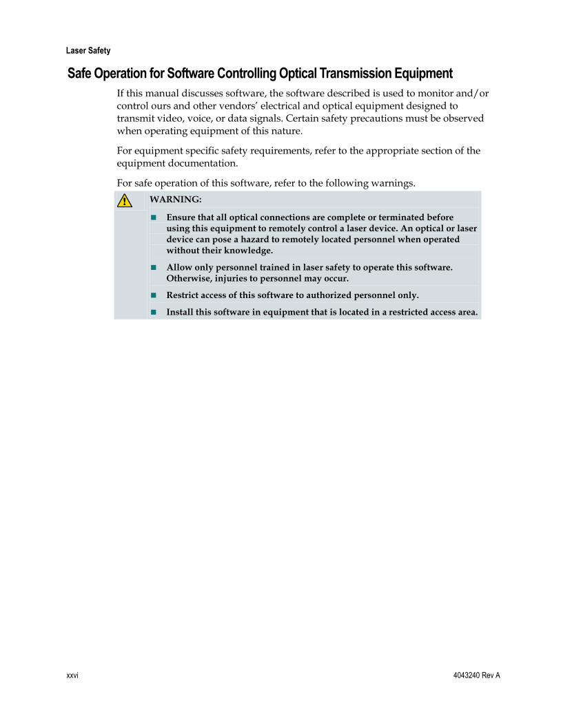
Safe Operation for Software Controlling Optical Transmission Equipment
If this manual discusses software, the software described is used to monitor and/or control ours and other vendors’ electrical and optical equipment designed to transmit video, voice, or data signals. Certain safety precautions must be observed when operating equipment of this nature.
For equipment specific safety requirements, refer to the appropriate section of the equipment documentation.
For safe operation of this software, refer to the following warnings.
WARNING:
Ensure that all optical connections are complete or terminated before using this equipment to remotely control a laser device. An optical or laser device can pose a hazard to remotely located personnel when operated without their knowledge.
Allow only personnel trained in laser safety to operate this software. Otherwise, injuries to personnel may occur.
Restrict access of this software to authorized personnel only.
Install this software in equipment that is located in a restricted access area.

Laser Safety
4043240 Rev A xxvii
Warning Labels The following illustration displays the warning label on this equipment.


4043240 Rev A 1
Introduction
This chapter provides streamlined step-by-step instructions for installing and configuring the platform hardware and firmware. Later chapters of this guide provide more detailed information on platform design, operation, and maintenance.
1 Chapter 1 Quick Start Guide
In This Chapter
Step 1: Install the Chassis in a Rack ...................................................... 2
Step 2: Make Chassis-to-Chassis ICIM Connections .......................... 3
Step 3: Make Electrical Power Connections ........................................ 6
Step 4: Install the ICIM ......................................................................... 13
Step 5: Set Network Parameters from the Command Line Interface (CLI)........................................................................................ 14
Step 6: Connect the ICIM to the Network ......................................... 18
Step 7: Install Modules in the Chassis ................................................ 20
Step 8: Set Additional Parameters via CLI (Optional) .................... 22
Step 9: Set and Verify SNMP Community Strings ........................... 23
Step 10: Perform Chassis-to-Chassis ICIM Activation (Optional) ............................................................................................... 25
Step 11: Make Changes to Traps and Enterprise MIBs .................... 26
Step 12: Make Physical Connections to Modules ............................. 28
Step 13: Verify System Release and Module Firmware Versions .................................................................................................. 29
Step 14: Install and Use the Firmware Update (SOUP) Utility (Optional) ............................................................................................... 30

Chapter 1 Quick Start Guide
2 4043240 Rev A
Step 1: Install the Chassis in a Rack
To Install the Chassis in a Rack
WARNING:
The chassis weighs approximately 30 lbs. empty and 60 lbs. fully loaded. To avoid personal injury and equipment damage, use safe handling and lifting practices in accordance with your organization's procedures.
Complete the following steps to mount the chassis in the rack.
1 If necessary, remove and reattach the chassis mounting brackets. The chassis ships from the factory with brackets installed for a 19-inch rack. When using a 23-inch rack, remove the mounting brackets and reattach them so that the wider bracket section protrudes from the chassis. Use a torque wrench to tighten the bracket mounting screws to 12 to 14 in-lbs (1.36 to 1.58 Nm).
2 Position the chassis in the rack with the fan tray installed, but otherwise empty.
3 Insert a mounting screw through each of at least four mounting holes on chassis front panel, and then into the rack.
4 Use a medium-sized Phillips-head screwdriver to tighten each mounting screw until it is tight.
5 Install additional cable and fiber management hardware as needed, in accordance with local practice.
Note: The instructions and illustration above describe a typical installation in a 19-inch rack. Installation details may vary depending on the mechanical configuration of the chassis mounting accessories.

Step 2: Make Chassis-to-Chassis ICIM Connections
4043240 Rev A 3
Step 2: Make Chassis-to-Chassis ICIM Connections
Chassis-to-Chassis ICIM Connections
This platform allows an ICIM (ICIM2 or ICIM2-XD) located in one chassis to monitor and control application modules located in several other chassis. To establish chassis-to-chassis ICIM communication, use the ICIM IN and ICIM OUT connectors located on the chassis interface panel.
Complete the following steps to establish chassis-to-chassis ICIM communication:
1 Connect a cable from ICIM OUT on the chassis containing the ICIM to ICIM IN on the second chassis.
2 If required, connect a second cable from ICIM OUT on the second chassis to ICIM IN on the third chassis.
3 If required, connect a third cable from ICIM OUT on the third chassis to ICIM IN on the fourth chassis.
Note: An ICIM2 or ICIM2-XD can control up to 64 application modules in a chassis daisy-chain of no more than 4 chassis.
ICIM IN and ICIM OUT Connectors
Every chassis has a DB9 ICIM IN and a DB9 ICIM OUT connector for the purpose of chassis-to-chassis ICIM connections. ICIM IN is a female connector and ICIM
OUT is a male connector.
To Make ICIM IN and ICIM OUT Cable Connections
Complete the following steps to make chassis-to-chassis ICIM IN and ICIM OUT
connections.
1 Connect the serial extension cable from the ICIM OUT of the chassis containing the ICIM to the ICIM IN connector of the second chassis.
2 Change the chassis ID numbers as needed to give each chassis an appropriate unique ID number. See To Change the Chassis ID Number below for further details.
3 Connect a serial extension cable from the ICIM OUT of the second chassis to the ICIM IN of the third chassis.

Chapter 1 Quick Start Guide
4 4043240 Rev A
4 Continue this daisy-chain connection until all chassis are connected.
5 The ICIM OUT port of the last chassis in the daisy-chain must be terminated with an ICIM OUT terminator, part number 4013014, which ships with the ICIM.
TP477
ICIM Out Terminator
Serial Extension
Cable
Chassis with ICIM
Chassis
Chassis
ICIM OutEM In
ICIM Out
ICIM OutICIM In
ICIM In
Chassis
ICIM OutICIM In
Serial Extension
Cable
Serial Extension
Cable
Note:
All chassis connected in this daisy-chain must be powered and have a fan tray or fan assembly installed. For correct operation, proper cooling of the chassis must be maintained over the specified temperature range.
A single chassis equipped with an ICIM must also have its ICIM OUT port terminated with an ICIM OUT terminator, part number 4013014. The ICIM OUT terminator ships with the ICIM.
To Change the Chassis ID Number
The number that appears in the chassis ID switch on the front panel of the chassis in which the ICIM is installed indicates the value for the chassis ID. Valid chassis ID values are 00 to 99 inclusive. However, the use of 00 as the chassis ID value is not recommended in some circumstances, as the following caution explains.
CAUTION:
Setting the chassis ID to 00 is not recommended as it causes the entity MIB to violate RFC-2737 by creating an invalid object identifier. This may affect operation with some management systems that use the entity MIB. In particular, attempts to access the fans (in virtual slot 0) in chassis 00 will fail if made via serial TNCS (or ROSA-EM) or LCI.

Step 2: Make Chassis-to-Chassis ICIM Connections
4043240 Rev A 5
Complete the following steps to change the chassis ID number.
1 Locate the chassis ID number at upper right on the front panel of each chassis. The chassis ID number is on a pushbutton scroll that can be used to set the number to a two-digit value from 01 to 99.
2 Use the pushbutton scroll as needed to set each chassis ID number to a unique value.
Note: The chassis numbering scheme used is discretionary, except that each interconnected chassis must have a unique ID number.
ICIM IN and ICIM OUT Cables
The cable required for both ICIM IN and ICIM OUT connections is a shielded 9-wire serial extension cable, DB9 Female to DB9 Male. This cable can be purchased locally or from the factory. The chassis data sheet lists the part number for a 6-foot DB9 Female to DB9 Male serial extension cable. The connectors are a serial 9-pin D-shell (EIA 574/232).

Chapter 1 Quick Start Guide
6 4043240 Rev A
Step 3: Make Electrical Power Connections
Electrical Power Connections
Electrical power is supplied to the chassis through one or two power supplies that install from the front. AC or DC power supplies are available, allowing the chassis to operate from either utility AC power or from -48 VDC supplied by a battery room or other source.
Note: The DC return terminal of the power supplies is isolated, i.e., not connected to the chassis framework.
Important: Tie the system to earth ground via the ground stud.
Chassis Wiring and Fusing
Important: All chassis configurations require an external fuse or circuit breaker and #16 AWG wiring for both power and grounding. AC and DC current ratings differ, as further explained below.
AC Power Systems
Power for AC power supplies enters the chassis via a dedicated IEC power inlet for each power supply module.
Confirm that the IEC power cord or cords supplied with the chassis have the correct plug configuration for the country of use.
The voltage input range for AC systems is 100 to 240 VAC, single phase, 50-60 Hz.
AC input current is 14 A maximum. The chassis should be connected to a single outlet circuit with fuse or circuit breaker overcurrent protection rated 15 A minimum.

Step 3: Make Electrical Power Connections
4043240 Rev A 7
Important:
Use only a grounded electrical outlet when connecting the unit to a power source. If you do not know whether the outlet is grounded, consult with a qualified electrician.
Maintain reliable earth grounding of rack-mounted equipment. Pay particular attention to supply and ground connections made via power strips or any method other than direct connection to the branch circuit.
DC Power Systems
External -48 VDC operating power for each DC power supply module enters the chassis via a dedicated DC power inlet.
The voltage input range for DC power systems is -40 VDC to -72 VDC.
Use #16 AWG wire for DC field wiring. The #16 AWG wiring from the external -48 VDC supply is attached to a 3-pin terminal block which, in turn, plugs into the DC power inlet.
Insert the bare end of an insulated wire into each inlet on the terminal block and tighten the corresponding screw to capture the wire in the terminal block.
After terminating the cable, twist the conductors loosely (a full turn every few inches is sufficient).
As installed in the DC power connector, the top pin of the terminal block carries -48 VDC, the middle pin is the return, and the bottom pin is chassis ground.
Connect the chassis to a reliably grounded DC power source that is electrically isolated from the AC power source.
Important:
Branch circuit overcurrent protection must be provided by a fuse or circuit breaker with a voltage rating of 72 VDC minimum and a current rating of 18 A maximum.
The DC field wiring must include a readily accessible disconnect device that is suitably approved and rated.

Chapter 1 Quick Start Guide
8 4043240 Rev A
Earth-Grounding Conditions
The chassis is designed to permit connection of the earthed conductor of the DC supply circuit to chassis ground. Before making this connection, confirm that all of the following conditions are met:
The chassis is connected directly to the DC supply system earthing electrode conductor or to a bonding jumper from an earthing terminal bar or bus to which the DC supply system earthing electrode conductor is connected.
The chassis is located in the same immediate area as other equipment connected between the earthed conductor of the same DC supply circuit and earthing conductor, such as in an adjacent cabinet. Also, the point of earthing of the DC system must not be earthed elsewhere.
The DC power source is located within the same premises as the chassis.
There are no switching or disconnecting devices in the earthed circuit conductor between the DC source and the point of connection of the earthing electrode conductor.
DC Power Inlet Illustration
The power supplies receive electrical power through the power inlets installed in the chassis. All power inlets are installed at the factory.

Step 3: Make Electrical Power Connections
4043240 Rev A 9
The following illustration shows the location of DC power inlets on the front-access chassis.

Chapter 1 Quick Start Guide
10 4043240 Rev A
The following illustration shows the location of AC power inlets on the rear-access chassis.
To Install the DC Power Cord
Complete the following steps to install the DC power cord for each DC power supply.
1 Locate the DC wire terminal block(s) either pre-installed in each DC power inlet or in a bag with the chassis documentation.
2 Remove the terminal block and note the locations of the top, middle, and bottom terminals as shown below.
3 Attach a #12 AWG power cable from the fuse panel to the DC wire terminal block that was shipped with the chassis. Attach the conductors to the terminal block as follows:
Top terminal: -48 VDC conductor
Middle terminal: Return conductor
Bottom terminal: Not used

Step 3: Make Electrical Power Connections
4043240 Rev A 11
Note: The DC return terminal of the power supplies is isolated, i.e., not connected to the chassis framework.
Important: Tie the system to earth ground via the ground stud.
To Install the AC Power Cord
There is a separate and independent AC inlet for each power supply slot in the chassis. Therefore, for operation of dual AC power supplies, two AC power cords must be installed.
Complete the following steps to install the AC power cord(s).
1 Locate the AC power inlet(s) on the chassis.
2 Plug the female end of the power cable that was shipped with the power supply into the AC power inlet.
3 Attach the male end of the power cord(s) to the electrical source(s).
To Install the Power Supply in the Chassis
This procedure assumes that the power inlet has been installed, the appropriate power cord has been connected, and power has been applied to the chassis.
1 Facing the front of the chassis, position the bottom of the power supply on the module guide of slot 1 (extreme left) of the chassis.
2 Align the top and bottom ridges on the power supply with the module guide slots in the chassis. You should be able to see the fiber guides at the bottom of the chassis and the module guide slots as shown below.

Chapter 1 Quick Start Guide
12 4043240 Rev A
3 Locate the two ejector levers on the left of the power supply module. Swing the ejectors out so they are perpendicular to the module front panel.
4 Gently slide the power supply into the chassis until its power and communications connections join connectors on the back plane bus. Do not force the module into the chassis. If properly aligned, it should slide in with minimal force.
5 Slowly press the module ejector levers toward the chassis so that their jaws engage with the mounting flange in the chassis. Confirm that the ejectors pull the power supply toward the mounting flange so that its back-panel connectors mate with the connectors at the rear of the chassis. Continue pressing the ejectors until they both lie parallel to the module front panel.
6 If you are installing a second power supply into slot 3, repeat steps 1 through 5, then continue with step 7.
7 Verify that the green LED illuminates, indicating that the power supply is now operating.
8 Confirm that the fan tray is operational. The fans should be audible once the power supply is operating.
9 Hand-tighten the screw at the top of the power supply to secure it in the chassis. Use a 3/8-in. flat-blade screwdriver to secure. Do not over-tighten.

Step 4: Install the ICIM
4043240 Rev A 13
Step 4: Install the ICIM
To Install the ICIM2
Complete the following steps to install the ICIM in the chassis.
1 Facing the front of the chassis, position the bottom of the ICIM on the slide of slot 15 (extreme right) of the chassis.
2 Align the top and bottom ridges on the ICIM with the module guide slots in the chassis.
3 Locate the two ejector levers on the left of the ICIM. Swing the ejectors out so they are perpendicular to the module front panel.
4 Gently slide the ICIM into the chassis until its power and communications connections join connectors on the back plane bus. Do not force the ICIM into the chassis. If properly aligned, it should slide in with minimal force.
5 Slowly press the ICIM ejector levers toward the chassis so that their jaws engage with the mounting flange in the chassis. Confirm that the ejectors pull the ICIM toward the mounting flange so that its back-panel connectors mate with the connectors at the rear of the chassis. Continue pressing the ejectors until they both lie parallel to the module front panel.
6 Hand-tighten the screw at the top of the ICIM to secure it in the chassis. Use a 3/8-in. flat-blade screwdriver to secure. Do not over-tighten.

Chapter 1 Quick Start Guide
14 4043240 Rev A
Step 5: Set Network Parameters from the Command Line Interface (CLI)
1 Connect one end of a DB-9 to DB-9 straight-through serial cable to an available COM port on the personal computer, and the other end to the ICIM front-panel serial port.
2 Open a HyperTerminal session on your laptop (or desktop) PC that you will use to connect to the ICIM. The HyperTerminal program is typically found at:
Start\All Programs\Accessories\Communication\Hyperterminal
The new Connection Description dialog box appears.
3 Type in a name for the connection, select an icon of your choice, and click OK. The Connect To dialog box appears.
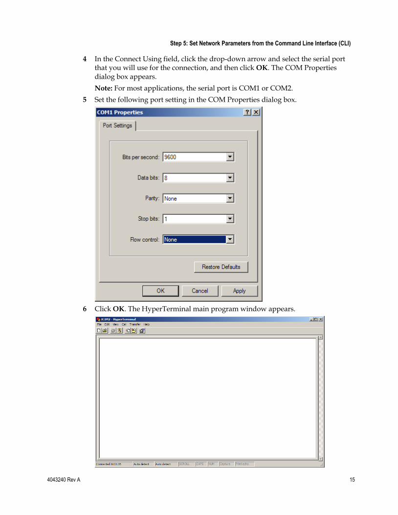
Step 5: Set Network Parameters from the Command Line Interface (CLI)
4043240 Rev A 15
4 In the Connect Using field, click the drop-down arrow and select the serial port that you will use for the connection, and then click OK. The COM Properties dialog box appears.
Note: For most applications, the serial port is COM1 or COM2.
5 Set the following port setting in the COM Properties dialog box.
6 Click OK. The HyperTerminal main program window appears.

Chapter 1 Quick Start Guide
16 4043240 Rev A
7 On the File menu, click Save to save the settings.
8 Wait for the ICIM boot to finish. Once finished, press Enter to display the ICIM login prompt:
Scientific-Atlanta Intelligent Communications Interface Module (ICIM) --------------------- W A R N I N G --------------------- Unauthorized or improper use of this system may result in administrative disciplinary action and civil or criminal penalties. By continuing to use this system you indicate your awareness of and consent to these terms and conditions of use. LOG OFF IMMEDIATELY if you do not agree to the conditions stated in this warning. login:
9 Log in using the default username Administrat0r and the default password AdminPassw0rd. Note the 0 (zero) character in each string.
Scientific-Atlanta Intelligent Communications Interface Module (ICIM) login: Administrat0r Password: AdminPassw0rd
Successful login will return the following prompt: login: Administrat0r Password: User Administrat0r logged in successfully on 11/13/06 at 15:25:35 Previous successful login was on 11/13/06 at 15:22:16 There were no failed attempts to login with this user id previously CLI>
10 Enter the ICIM submenu by typing icim at the CLI> prompt.
CLI> icim
Successful entry into the ICIM menu tree will return the following prompt: ICIM>
11 Configure the shelf (chassis) IP address, subnet mask, gateway, and clock using the following commands: set ip xxx.xxx.xxx.xxx set subnet xxx.xxx.xxx.xxx set gateway xxx.xxx.xxx.xxx set clock "month/day/year hour:minute:second"
Note:
Be sure to include the quote symbols, e.g., set clock "3/15/2006 13:09:51".
Clock time is in the 24-hour format.
12 If desired, enable IPsec (disabled by default) by following the instructions in Setting Up IPsec (on page 315).
13 To enable these changes, reboot the ICIM as follows: ICIM> reboot

Step 5: Set Network Parameters from the Command Line Interface (CLI)
4043240 Rev A 17
14 After the ICIM reboots, repeat the login steps described above to return to the ICIM command prompt. Then use the show command to verify each of the above changes, as follows:
show ip show subnet show gateway show clock
15 Type logout, and then press Enter to exit the session.
16 Remove the serial cable. It is no longer required.
Important:
For Telnet operation, the computer you are using must have a network connection through which it can reach the ICIM at its IP address.
No more than four Telnet sessions are allowed at one time.
CAUTION:
Always use the Logout command to close a serial port or Telnet CLI session. Closing a serial port session without issuing the Logout command leaves the session open for a possible future connection. This may allow unauthorized access by a new user if the previous user had a higher authorization privilege level.

Chapter 1 Quick Start Guide
18 4043240 Rev A
Step 6: Connect the ICIM to the Network 1 Using a Category 5 Ethernet (CAT5) cable, connect the front panel Ethernet port
of the ICIM to your local network.
2 Verify connectivity by pinging the ICIM IP address. For example: c:\> ping 172.18.50.100
Note:
The ICIM must have an IP address assigned as directed in Step 5: Set Network Parameters from the Command Line Interface (CLI) (on page 14). If not completed already, perform this step before continuing with these instructions.
When using IPsec, the ICIM and all computers with which it communicates must be set up for IPsec. For detailed instructions, see Setting Up IPsec (on page 315).
3 Follow the steps described in To Set Up a Telnet CLI Session (on page 18) to set up a Telnet session with the ICIM.
To Set Up a Telnet CLI Session
Complete the following steps to initiate a CLI session with the ICIM using Telnet.
Important:
The ICIM must have an IP address assigned before performing this procedure.
When using IPsec, the ICIM and all computers with which it communicates must be set up for IPsec. For detailed instructions, see Setting Up IPsec (on page 315).
1 Open a DOS window on the PC that will connect to the ICIM.
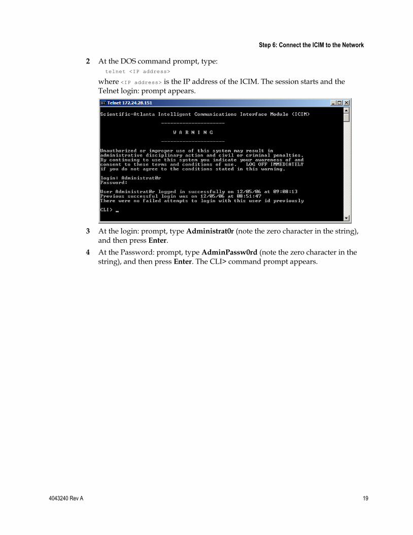
Step 6: Connect the ICIM to the Network
4043240 Rev A 19
2 At the DOS command prompt, type: telnet <IP address>
where <IP address> is the IP address of the ICIM. The session starts and the Telnet login: prompt appears.
3 At the login: prompt, type Administrat0r (note the zero character in the string), and then press Enter.
4 At the Password: prompt, type AdminPassw0rd (note the zero character in the string), and then press Enter. The CLI> command prompt appears.

Chapter 1 Quick Start Guide
20 4043240 Rev A
Step 7: Install Modules in the Chassis
To Install the Module
WARNING:
Avoid damage to your eyes! Do not look into any optical connector while the system is active. Even if the unit is off, there may still be hazardous optical levels present.
CAUTION:
Before removing a transmitter module from a Prisma II Chassis under power: 1) Disable the transmitter output by setting TxEnable=0 (Disable) from CLI or your network management system; and 2) Detach the fiber optic jumper from the transmitter output port. Failure to perform both steps may result in damage to downstream amplifier modules due to higher than normal transmitter output.
Complete the following steps to install the module in the chassis.
1 Locate the fiber guides at the bottom of the chassis and the module guide slots inside the chassis as shown in the following illustration.
2 Align the top and bottom ridges on the module with the module guide slots on the chassis.
3 Locate the two ejector levers on the left of the module. Swing the ejectors out so they are perpendicular to the module front panel.

Step 7: Install Modules in the Chassis
4043240 Rev A 21
4 Gently slide the module into the chassis until its power and communications connections join connectors on the back plane bus. Do not force the module into the chassis. If properly aligned, it should slide in with minimal force.
5 Slowly press the module ejector levers toward the chassis so that their jaws engage with the mounting flange in the chassis. Confirm that the ejectors pull the module toward the mounting flange so that its back-panel connectors mate with the connectors at the rear of the chassis. Continue pressing the ejectors until they both lie parallel to the module front panel.
6 Hand-tighten the screw at the top of the module to secure it in the chassis. Use a 3/8-in. flat-blade screwdriver to secure. Do not over-tighten.
7 Fill any unused chassis slots with module blanks to guarantee proper cooling air flow.

Chapter 1 Quick Start Guide
22 4043240 Rev A
Step 8: Set Additional Parameters via CLI (Optional)
Additional parameters may be set as needed from the command line interface (CLI) for each application module installed.
Refer to Prisma II Permitted CLI Commands (on page 371) and the appropriate configuration guide for information and additional instructions on available commands and using the CLI.
The following CLI commands are pertinent to most installations.
To Set Additional Users for ICIM Access
Refer to the appropriate configuration guide for CLI and ICIM Web Interface login settings information.
Note: It is strongly recommended that a new administrator login be created and that the default administrator login be removed.
The table below lists the ICIM mode CLI commands for setting user login parameters.
Commands Description
ICIM > show user Shows all users
ICIM > user change password [user name] Changes user password
ICIM > user add [user name] [access level] enable Adds a user
ICIM > user delete [user name] Deletes a user
Note: User names and passwords must be 6 to 14 characters long, and must include at least 1 number.

Step 9: Set and Verify SNMP Community Strings
4043240 Rev A 23
Step 9: Set and Verify SNMP Community Strings At the CLI ICIM> command prompt, use the set command to change the SNMP Community write, read, and trap strings to corresponding user-defined strings to allow for remote monitoring and control via a network management system (NMS). After entering these commands, use the info command to verify the new settings.
The sample dialog below shows how to enter these commands. In the example below:
myCommWriteString is the user-defined community write string.
myCommReadString is the user-defined community read string.
myCommTrapString is the user-defined community trap string.
Refer to SNMP Management (on page 193) for SNMP parameter information.
From the CLI command prompt, switch to ICIM command mode and define SNMP Read, Write, and Trap Community strings, as shown below.
CLI> icim
ICIM> set commwrite “myCommWriteString” NOTE: This change will not fully take effect until the ICIM is restarted. Until that time, some operations will not perform as expected.
SUCCESS!
ICIM> set commread “myCommReadString” NOTE: This change will not fully take effect until the ICIM is restarted. Until that time, some operations will not perform as expected.
SUCCESS!
ICIM> set commtrap “myCommTrapString” NOTE: This change will not fully take effect until the ICIM is restarted. Until that time, some operations will not perform as expected.
SUCCESS!
You can then verify the community string settings, as follows.
ICIM> info commread commwrite commtrap
COMMREAD COMMWRITE COMMTRAP
myCommReadString myCommWriteString myCommTrapString
SUCCESS!
ICIM>

Chapter 1 Quick Start Guide
24 4043240 Rev A
Note:
It is strongly recommended that you restart the ICIM after changing any of the community strings. Otherwise, some operations will continue to work normally, while others will appear to fail.
It is strongly recommended that you create new SNMP community strings and remove the default SNMP community strings. Default SNMP community string values are listed below.
SNMP Community String Default Value
Read Community public
Write Community private
Trap Community SNMP_traps

Step 10: Perform Chassis-to-Chassis ICIM Activation (Optional)
4043240 Rev A 25
Step 10: Perform Chassis-to-Chassis ICIM Activation (Optional)
Once the chassis are interconnected, the shared ICIM should be forced to search for all new modules, rather than be allowed to find them incrementally over the course of a polling cycle.
The recommended method for forcing a search for new modules is to reboot the ICIM. This can be accomplished either by physically removing and reinserting the ICIM or by issuing a reboot command to the ICIM via the CLI interface.
To reboot the ICIM via CLI, open a console or Telnet session and type the following commands at the CLI prompt.
CLI> icim
ICIM> reboot
The response will be:
The ICIM2 is about to reboot. This will end all current login and web sessions Are you sure you want to proceed (Yes/No)> yes
SUCCESS! ICIM>
Scientific-Atlanta Intelligent Communications Interface Module (ICIM) ---------------------
W A R N I N G
---------------------
Unauthorized or improper use of this system may result in administrative disciplinary action and civil or criminal penalties. By continuing to use this system you indicate your awareness of and consent to these terms and conditions of use. LOG OFF IMMEDIATELY if you do not agree to the conditions stated in this warning.
login:
Each of the additional modules will then be added to the ICIM polling cycle.
Note: Use of the CLI reboot command is preferred over the updateid command in this case because a reboot will maintain synchronization with the element management system.

Chapter 1 Quick Start Guide
26 4043240 Rev A
Step 11: Make Changes to Traps and Enterprise MIBs
Trap settings and other parameters can be set in one of several ways:
Using Simple Network Management Protocol (SNMP) commands. Refer to SNMP Management (on page 193) for details on accessing the ICIM MIB tables.
Using the Command Line Interface (CLI) Traps Enable command. Refer to the appropriate configuration guide for details on using the Traps Enable command.
Using the ICIM Web Interface, which requires no knowledge of SNMP or CLI. For further information, refer to the appropriate configuration guide.
Once this is accomplished, changes can be made to the ICIM Trap tables, of which there are 10 entries (one for each destination IP address).
Following are the objects in the p2TrapRecvEntry table that should be set.
MIB Object Value
p2TrapRecvEnable 1-disabled; 2-enabled
p2TrapRecvAddr IP address of trap receiver
p2TrapRecvTelcoAlarm 1-disabled; 2-enabled
MIB Software
MIBs associated with the software system release are available and should be compiled in your SNMP tool. They are labeled as follows:
SCIATL-PRISMAII-ICIM-MIB.mib
SCIATL-PRISMAII-MODULE-MIB.mib

Step 11: Make Changes to Traps and Enterprise MIBs
4043240 Rev A 27
Trap Overview
The Prisma II system can be configured to provide various alarm and warning conditions to an NMS or system monitor application.
There are nine different trap categories that can be independently enabled to provide the desired level of information on events occurring in a system. These traps can be forwarded to up to 10 different IP addresses. The trap filtering can be configured uniquely for each user.
See SNMP Management (on page 193) for trap details.
Note: All trap types (module insertion, alarm events, etc.) are reported through the Enhanced Alarm trap. Therefore, only the Enhanced Alarm traps are enabled by default, and this is the recommended configuration.

Chapter 1 Quick Start Guide
28 4043240 Rev A
Step 12: Make Physical Connections to Modules Once all configuration changes are complete, you are ready to make fiber-optic and RF cable connections for each module as appropriate.
To Connect Optical Cables
CAUTION:
High power density exists on fiber when optical power is present. To avoid microscopic damage to fiber mating surfaces, turn off optical power or reduce power below 15 dBm before making or breaking optical connections.
Complete the following steps for each optical cable connection to be made and on every module to be installed.
1 Clean the end of the fiber to be connected as described in Cleaning Optical Connectors (on page 81).
2 Connect the optical cable to the module connector.
3 Route the cable to the appropriate destination.
4 Clean the remaining cable end, and then connect the cable to the mating module connector.
Note: Remember to observe minimum bend radius and other accepted handling practices when working with fiber-optic cables.
5 After cable installation is complete, return the module control settings to their original states.
To Connect RF Cables
Complete the following steps for each RF cable connection to be made.
1 Connect the RF cable to the appropriate connector on the connector interface panel.
2 Route the cable to the appropriate destination.

Step 13: Verify System Release and Module Firmware Versions
4043240 Rev A 29
Step 13: Verify System Release and Module Firmware Versions
To check the current firmware revision levels in all modules in the ICIM domain, enter the following CLI command at the ICIM> prompt:
ICIM> show domain
A column labeled ACTIVEREV in the response lists the active firmware revision numbers for each module in the domain. Each module firmware revision should be compatible with the revision number of the system release firmware. For information on module and system release firmware compatibility, contact your customer service representative.
If any modules report a firmware version that is not compatible with the system release firmware, use the procedures described in the next step to update the module firmware.

Chapter 1 Quick Start Guide
30 4043240 Rev A
Step 14: Install and Use the Firmware Update (SOUP) Utility (Optional)
The Prisma II Software Upgrade Program (SOUP) is a user-friendly utility that allows users to perform firmware upgrades on Prisma II modules. The SOUP utility simplifies the firmware upgrade process by providing a graphical user interface (GUI) that is easy to use and requires little training.
When connected to a chassis, the SOUP utility shows the user the current versions of firmware on all modules and allows the user to download and activate other versions from system release files. The SOUP works together with the ICIM2 to send the binary image files and appropriate commands to the modules to upgrade their firmware. As the modules are being upgraded, the SOUP displays relevant progress information to the user.
To Install the SOUP on Windows
Complete the following steps to install the Prisma II SOUP on Windows.
1 Locate the Prisma II SOUP installation file on www.cisco.com/support and copy the file to your Windows desktop.
Note: If you need help locating the SOUP installation program, see Customer Information (on page 369) to locate customer support for your area.
2 Double-click the Prisma II SOUP installation icon to start the installation.
3 Follow the instructions of the installation wizard.
After the installation is complete, you will have an icon on the desktop to launch the SOUPLauncher application. There will also be a program group called Prisma II SOUP on your Start button menu.
To Use the SOUP Utility
After the SOUP utility is launched through SOUPLauncher, it attempts to connect to the ICIM and retrieve information about all the modules it manages. After retrieving the module information, the SOUP connects to the FTP server holding the system release files and retrieves the firmware versions available for each module. This information is then displayed to the user in the application main screen.
For additional details on using SOUP, see Remote Firmware Download Feature (on page 299).

Step 14: Install and Use the Firmware Update (SOUP) Utility (Optional)
4043240 Rev A 31
To Uninstall the SOUP on Windows
Complete the following steps to remove the Prisma II SOUP from your computer.
1 Open the Control Panel from the Windows Start menu.
2 From the Control Panel, open the Add or Remove Programs application.
3 Find and choose the Prisma II SOUP entry in the list of installed programs. If the entry is not present, the program is not installed on the computer or was not installed properly.
4 Click the Change/Remove button.
5 Follow the instructions of the uninstall wizard.


4043240 Rev A 33
Overview
This guide describes the Cisco® Prisma® II Platform and application modules. The Prisma II Chassis, Power Supplies, Fan Tray, application modules, and external control systems make up the Prisma II Platform.
Purpose
This guide provides the requirements for implementing the Prisma II Platform components and external control systems.
Who Should Use This Document
This document is intended for authorized service personnel who have experience working with similar equipment. The service personnel should have appropriate background and knowledge to complete the procedures described in this document.
Qualified Personnel
WARNING:
Allow only qualified and skilled personnel to install, operate, maintain, and service this product. Otherwise, personal injury or equipment damage may occur.
Only appropriately qualified and skilled personnel should attempt to install, operate, maintain, and service this product.
2 Chapter 2 Introduction

Chapter 2 Introduction
34 4043240 Rev A
Scope
This guide discusses the following topics.
Descriptions of Prisma II Platform chassis and application modules
Installation procedures
Configuring the equipment
Local and remote system management
User management
Remote software download and firmware update
CLI command reference
Descriptions of module parameters
Document Version
This is the first release of this guide (Rev A).
In This Chapter
Related Publications ............................................................................. 35
Prisma II Platform Description ........................................................... 36
Prisma II Chassis ................................................................................... 39
Prisma II Fan Tray ................................................................................ 45
Prisma II Power Supply ....................................................................... 47
Prisma II ICIM2 ..................................................................................... 50
Module Back Panel ............................................................................... 52

Related Publications
4043240 Rev A 35
Related Publications You may find the following publications useful as you implement the procedures in this document.
Cisco Prisma II Enhanced Management System Configuration Guide, System Release 2.05.20, part number 4038978 (also applicable to System Release 2.05.25)
Prisma II High Power Optical Amplifiers Installation and Operation Guide, part number 4010846
Prisma II 1550 nm Gain-Flattened Optical Amplifier Installation and Operation Guide, part number 4000067
Prisma II 1550 nm FTTx Transmitter Installation and Operation Guide, part number 4008715
Prisma II 1550 nm Transmitters Installation and Operation Guide, part number 739259
Prisma II Optical Amplifiers Installation and Operation Guide, part number 739260
Prisma II Forward and Reverse Headend Driver Amplifiers Installation and Operation Guide, part number 4006323
Prisma II Optical Switch Installation and Operation Guide, part number 715188
Prisma II Forward Receiver Installation and Operation Guide, part number 713376
Prisma and Prisma II Platform Maintenance and Troubleshooting Service Guide, part number 4000326
Prisma II 1310 nm Reverse Transmitter Installation and Operation Guide, part number 715190
Prisma II Forward and Reverse Headend Driver Amplifier Installation and Operation Guide, part number 715189
Prisma II Reverse Data Receiver and Reverse Video Receiver Installation and Operation Guide, part number 713378
Prisma II High Density Dual Reverse Receiver Installation and Operation Guide, part number 4015908
Prisma II High Density Forward Receiver Installation and Operation Guide, part number 4020002
Prisma II 1310 nm High Density Transmitter Installation and Operation Guide, part number 4009700
Prisma II Multi-Wavelength High Density Transmitter Installation and Operation Guide, part number 4023013

Chapter 2 Introduction
36 4043240 Rev A
Prisma II Platform Description The Prisma II Platform is a configurable and expandable system for providing amplification, transmission, and switching functions to fiber-optic communications networks. The Prisma II Platform can be configured for use in a variety of environments, from CATV headends and hubs to telecommunications central offices.
Key features of the Prisma II Platform include the following:
High module density
Broad operating temperature range
Optimized design for rapid installation and setup
Support for local and remote system monitoring and control
In addition, Prisma II Platform chassis can be used together with Prisma II XD Platform chassis in the same network. A single Intelligent Control Interface Module 2 (ICIM2) can be used to control this network, whether it is an ICIM2 installed in a Prisma II Platform chassis or an ICIM2-XD installed in a Prisma II XD chassis.
Prisma II Platform Components
The Prisma II Platform consists of the following standard and optional products.
Prisma II Chassis
- Front-access chassis (standard)
- Rear-access chassis (optional)
Prisma II Fan Tray
Prisma II Power Supplies
Prisma II Intelligent Communications Interface Module 2 (ICIM2)
Prisma II application modules
Note: The ICIM2 can control up to 64 application modules in a chassis daisy-chain of up to 4 chassis. The daisy-chain can include both Prisma II and Prisma II XD chassis, provided that it does not exceed the maximum number of chassis or application modules.
The Prisma II chassis houses the other system components. A back plane bus at the rear of the chassis distributes electrical power to all modules and transports communication and control signals from the application modules to the ICIM2.

Prisma II Platform Description
4043240 Rev A 37
Prisma II Fan Tray
The chassis uses a negative pressure fan system that pulls input cooling air from the ambient environment. The fans are housed in a removable fan tray located at the top of the chassis for ease of maintenance.
A fan tray interface connects the back plane bus and the fan tray interconnect. A blind mate connector system is used to connect the fan tray to the back plane bus.
Prisma II Power Supplies
One or two Prisma II Power Supplies may be used. The power supplies are installed from the front of the chassis.
WARNING:
Normal operation and maintenance should be performed with two power supplies installed and operating. Removal and rapid reinsertion of a fan tray into an active chassis can result in temporary service interruption if only a single power supply is active. Inrush current protection circuitry requires a delay of two (2) or more seconds before reinsertion.
Power supplies are available for operation from AC utility power or from a nominal -48 VDC power source.
WARNING:
Any external power supply must provide proper electrical components to power the chassis or risk serious equipment damage or personal injury. Do not use any external power supply to power this product unless it has been approved by Customer Service.
ICIM2
The Prisma II Intelligent Communications Interface Module 2 (ICIM2) provides users with read-only access to monitor application module configuration settings, status monitoring, and alarm monitoring.
In addition, the ICIM2 front panel allows the user to enable and disable Service mode on certain Prisma II application modules.
MSO and MSO1 Configurations
With System Release 2.04.03, the ICIM is available in either of two software configurations to meet specific customer needs.
The MSO configuration omits support for user password management from the ICIM keypad.
The MSO1 configuration includes support user password management from the ICIM keypad.

Chapter 2 Introduction
38 4043240 Rev A
For more information about the MSO and MSO1 configurations, see ICIM Operation (on page 101).
Prisma II Application Modules
Prisma II application modules perform a prescribed set of independent functions such as transmitting, receiving, or amplifying. These modules are installed from the front of the chassis, are hot-swappable, and have plug-and-play capability.

Prisma II Chassis
4043240 Rev A 39
Prisma II Chassis The Prisma II Chassis houses the Fan Tray, one or two Prisma II Power Supplies, all application modules, and the ICIM2. It distributes electrical power to all modules, and provides strain relief and routing for optical cables connected to the various modules.
The chassis also transports communication and control signals from the application modules to the ICIM2. These signals enable system management via the ICIM2 front panel and by command line interface (CLI), hypertext transfer protocol (HTTP), Local Craft Interface (LCI), and Simple Network Management Protocol (SNMP) commands.
Through a common back plane bus, the chassis provides modules with electrical power, a common serial bus, a high-speed data bus to the ICIM2, and up to four RF connections to each module. An inter-module bus enables the application modules to be replaced even when the system is powered and fully operational.
Chassis Configuration
The chassis has 16 slots that can be populated with any of the following combinations:
1 power supply (occupies 2 slots) and up to 13 single-slot application modules
2 power supplies (occupies 4 slots) and up to 12 single-slot application modules
1 power supply (occupies 2 slots), 1 ICIM2 (occupies 2 slots), and up to 11 single-slot application modules
2 power supplies (occupies 4 slots), 1 ICIM2 (occupies 2 slots), and up to 10 single-slot application modules
Note: In single power supply configurations, slot 3 is open but cannot be used by an application module. Instead, a power supply module blank must be installed in slot 3 to maintain proper air flow inside the chassis.
The chassis supports the entire family of Prisma II modules including primary and redundant power supplies, the ICIM2, pre-amplifiers, hybrid amplifiers, optical transmitters, optical receivers, and an optical switch. The chassis accepts full-height application modules directly, and half-height high density modules through the use of a host module.
A chassis fan filter is located below the fiber guide (fiber routing tray). It is recommended that this filter be replaced yearly. The service interval can be adjusted depending on the equipment environment.

Chapter 2 Introduction
40 4043240 Rev A
Typical Chassis Block Diagram
The block diagram below shows a typical Prisma II Chassis configuration with two power supplies, an ICIM2, and several application modules installed.

Prisma II Chassis
4043240 Rev A 41
Front-Access Chassis
The illustration below shows a front-access chassis with two power supplies and the ICIM2 installed. The I/O connectors, RF connectors, and power inlets are located on the recessed bottom of the connector interface panel.
The front-access chassis configuration accommodates back-to-back installations, remote terminal (RT) installations, or other space limitations.

Chapter 2 Introduction
42 4043240 Rev A
Chassis Front Panel Features
Part Function
(Power) ON LED Illuminates when power is applied to the chassis.
ALARM LED Illuminates if there is a failure in the fan tray of the chassis.
LCI Port Provides an RS-232 serial local craft interface for an installed ICIM2
Chassis ID Switch Located at the top right of the front panel, allows the operator to assign an identification number to every chassis for addressing via the ICIM2 or through CLI or SNMP commands. When using the ICIM2, this number is referred to as the Shelf number.
Note: Each chassis connected to an individual ICIM2 must have a unique chassis ID number.
ESD Jack ESD (electrostatic discharge) jack, to be used prior to touching any modules.
ALARMS IN/ALARMS OUT
Allows for an ALARM OUT connection and an ALARM IN connection for each module slot in the chassis.
ICIM IN/ICIM OUT Allows one ICIM2 to control and monitor modules in more than one chassis. The ICIM IN and ICIM OUT connectors are located on the connector interface panel of the chassis.
EM IN/EM OUT An RS-485 bus that enables serial communication with the ICIM2 using Transmission Network Control System (TNCS) or another element management system.
Power Supply Inlets Either AC or DC power supplies can be installed in the chassis when the proper power inlets are installed. Primary and (optional) secondary power supplies are inserted from the front of the chassis. The power supply connectors mate with the factory-installed power inlet connectors on the back plane bus. The inlets differ with the type of power supply (AC or DC) used.
Ground Studs Grounding studs
RF Connectors Up to four RF connectors per chassis slot may be mounted on the connector panel. The numbers 2 and 4-16 across the top of the panel identify the corresponding chassis slot number. The letters A-D near the right edge of the panel identify the possible connector positions for each slot, with "A" indicating the primary RF input/output port.

Prisma II Chassis
4043240 Rev A 43
Chassis Back Plane Bus
The chassis back plane bus consists of the inside and the outside rear panel of the chassis through which power and communication signals are connected and distributed.
In addition to distributing electrical power and providing a common serial bus, the back plane bus also connects 4 RF ports (2 connectors are standard, 2 others are optional) to each of the 14 module connectors. The chassis is also available without RF ports.
The chassis back plane bus layout is shown below.
Prisma II Power Supplies
One or two Prisma II Power Supplies may be used. The power supplies are installed from the front of the chassis.
WARNING:
Normal operation and maintenance should be performed with two power supplies installed and operating. Removal and rapid reinsertion of a fan tray into an active chassis can result in temporary service interruption if only a single power supply is active. Inrush current protection circuitry requires a delay of two (2) or more seconds before reinsertion.
Power supplies are available for operation from AC utility power or from a nominal -48 VDC power source.

Chapter 2 Introduction
44 4043240 Rev A
WARNING:
Any external power supply must provide proper electrical components to power the chassis or risk serious equipment damage or personal injury. Do not use any external power supply to power this product unless it has been approved by Customer Service.
Back Plane Bus Connectors
Module connectors inside the chassis accommodate electrical power, digital signals, and analog signals. The connectors are self-guiding and allow a blind mate connection.

Prisma II Fan Tray
4043240 Rev A 45
Prisma II Fan Tray The Prisma II Fan Tray houses the fans that cool the chassis and its application modules. The fan tray also contains the sensor circuits that provide temperature and power supply status information to monitoring devices.
Fan Tray Configuration
The chassis ships with a rear-exhaust fan tray, which has its air exhaust ports on the back panel and a solid front panel.
A front-exhaust version of the fan tray is also available from the factory. Both configurations are accessed from the front of the chassis.
ICIM2 Block Diagram
The ICIM2 is illustrated in the block diagram below.
Fan Tray Installation
The fan tray is installed in the top of the chassis at the factory. It can be removed for maintenance or inspection by loosening the two screws located on either side of the front panel.
Important: Do not operate any chassis without a fan tray installed. For correct operation, proper cooling of the chassis must be maintained over the specified temperature range.

Chapter 2 Introduction
46 4043240 Rev A
WARNING:
Normal operation and maintenance should be performed with two power supplies installed and operating. Removal and rapid reinsertion of a fan tray into an active chassis can result in temporary service interruption if only a single power supply is active. Inrush current protection circuitry requires a delay of two (2) or more seconds before reinsertion.
Fan Tray Illustration (Top View)
Fan Tray Front Panel Features
Part Function
Alarm Indicator Red ON – Major Alarm active
Red Blinking – Minor Alarm active
Red OFF – No Alarm active
On Indicator Green ON – Power applied
Green OFF – Power not applied

Prisma II Power Supply
4043240 Rev A 47
Prisma II Power Supply The Prisma II Power Supply converts incoming utility power (AC or DC, depending on model) to the DC operating voltages needed by the application modules.
The Prisma II Platform is designed to accommodate up to two power supplies. The two power supply slots, 1 and 3, are located on the left side of the chassis.
In normal operation, the two power supplies share the load. If one power supply should fail, the remaining power supply will take the full load.
WARNING:
Normal operation and maintenance should be performed with two power supplies installed and operating. Removal and rapid reinsertion of a fan tray into an active chassis can result in temporary service interruption if only a single power supply is active. Inrush current protection circuitry requires a delay of two (2) or more seconds before reinsertion.
Electrical Input Voltages
The -48 VDC power supply accepts DC input in the range of -40 to –72 V DC.
The AC power supply accepts AC input in the range of 90 to 265 V AC.
Both types convert input power to three DC output power buses at +24 V, +5 V, and -5 V.
Power Inlets
Two power inlets are installed on the chassis connector interface panel at the factory to match the electrical power source at the installation site.
There are three power inlet options available:
-48 VDC
AC – 3 prong – Class I
AC – 2 prong – Class II (CE)
DC power inlets are provided with wire terminal blocks. These are inserted either in the power inlets themselves or in a bag with the chassis documentation.
Important: Use an equipotential bonding conductor to make a connection from the chassis ground stud to a reliable earthing mechanism at the installation site. For additional information, refer to EN 50083-1/A1:1977.

Chapter 2 Introduction
48 4043240 Rev A
Note: The chassis ships with a fan tray installed, but without a power supply or any application modules inserted.
Power Supply Block Diagram
A block diagram of the Prisma II Power Supply module (AC or DC input) is shown below.

Prisma II Power Supply
4043240 Rev A 49
Power Supply Front Panel Illustrations
Power Supply Front Panel Features
Part Function
Alarm Indicator Red ON – Major Alarm active
Red Blinking – Minor Alarm active
Red OFF – No Alarm active
On Indicator Green ON – Power applied
Green Blinking – Communicating with ICIM2
Green OFF – Power not applied

Chapter 2 Introduction
50 4043240 Rev A
Prisma II ICIM2 The ICIM2 provides a front-panel user interface to the Prisma II application modules. It also provides the interface between the modules and command line interface (CLI) or Simple Network Management Protocol (SNMP) remote management systems.
The ICIM2 can control up to 64 application modules through a daisy-chain of up to 4 chassis. The daisy chain can include both Prisma II Platform chassis and Prisma II XD Platform chassis in any combination within the maximum number of modules and chassis.
Important:
All chassis in a daisy-chain must be internally or externally powered and have a fan tray or fan assembly installed.
All chassis in a daisy-chain must have a unique chassis identification (ID) number.
To ensure communications with all application modules, only one ICIM2 or ICIM2-XD module may be installed per daisy-chain configuration.
MSO and MSO1 Configurations
With System Release 2.04.03, the ICIM is available in either of two software configurations to meet specific customer needs.
The MSO configuration omits support for user password management from the ICIM keypad.
The MSO1 configuration includes support user password management from the ICIM keypad.
For more information about the MSO and MSO1 configurations, see ICIM Operation (on page 101).

Prisma II ICIM2
4043240 Rev A 51
ICIM2 Illustration (Front Panel)
ICIM2 Front Panel Features
Part Function
LCD screen Displays the ICIM2 menus, alarms, and status information.
12-key numeric keypad
Used to navigate the ICIM2 menus.
Ethernet connector Directly connects the ICIM2 to an IP network. The ICIM2 Ethernet port is suitable for connection to intra-building wiring, non-exposed wiring or cabling only.
RS232 connector Used to connect a co-located PC to the Prisma II system for CLI communication and setup.

Chapter 2 Introduction
52 4043240 Rev A
Module Back Panel
Back Panel Connectors
Blind-mate connectors make it easy to install Prisma II modules. The push-on connector on the back of the module mates with the back plane bus connector inside the chassis. This 110-pin connector provides the following:
RF signal input connection (transmitter module only)
Electrical power input connection
Alarm communications
Status-monitoring communications
Communications and control connections
Power and Communications Connector
The power and communications connector on the back of the module mates with a connector inside the chassis and supplies power from the chassis to the module. This 110-pin connector also routes alarm and status-monitoring information from the module to the chassis.

4043240 Rev A 53
Introduction
This chapter describes site requirements, equipment, tools needed, and instructions for installation of the chassis and its application modules.
3 Chapter 3 Hardware Installation
In This Chapter
Before You Begin ................................................................................... 54
Site Requirements ................................................................................. 55
Mounting the Chassis in a Rack.......................................................... 58
Connector Interface Panel .................................................................... 60
Connecting the ICIM to Additional Chassis ..................................... 62
External Alarms Connections ............................................................. 66
Fan Tray ................................................................................................. 68
Chassis Fan Filter .................................................................................. 69
Installing the Power Supplies ............................................................. 71
Installing the ICIM2 .............................................................................. 76
Installing the Module in the Chassis .................................................. 78
Cleaning Optical Connectors .............................................................. 81
Connecting Optical Cables .................................................................. 83
Connecting RF Cables .......................................................................... 84

Chapter 3 Hardware Installation
54 4043240 Rev A
Before You Begin The chassis ships from the factory with a front-access connector interface panel mounted on the lower front of the chassis. This connector panel makes the I/O connectors, RF ports, and power inlets available at the front of the chassis.
Chassis with a rear-access connector interface panel are also available from the factory to meet a variety of configuration and space requirements.
Unpacking and Inspecting the Chassis
As you unpack the chassis, inspect it for shipping damage. If you find any damage, contact Customer Service. Refer to Customer Information (on page 369) for information on contacting Customer Service. Record the chassis serial number and date of installation for future reference.
Required Equipment and Tools
Before you begin, gather the equipment and tools listed in the following table.
You need . . . To . . .
a medium-sized Phillips-head screwdriver tighten the screws that secure the chassis to the equipment rack.
a mounting bracket. The chassis ships from the factory with gray mounting ears set for a 19-inch wide rack. If you are using a 23-inch wide rack, invert the ears to make the wider connection.
secure the chassis to the rack.

Site Requirements
4043240 Rev A 55
Site Requirements This section describes environmental, physical, and wiring requirements to be met prior to equipment installation. Before you begin, make certain that your installation site meets the requirements discussed in this section.
Operating Environment
CAUTION:
Avoid damage to this product! Operating this product outside the specified operating temperature limits voids the warranty.
Follow these recommendations to maintain an acceptable operating temperature of the equipment.
Keep cooling vents clear and free of obstructions.
Provide ventilation as needed using air-deflecting baffles, forced-air ventilation, or air outlets above enclosures, either alone or in combination.
Temperature at the air inlet must be between -40C and 65C (-40F and 149F). For chassis with one or more Prisma II Post-Amplifier FTTP modules installed,
air inlet temperature must be between -5C and 55C (23F and 131F).
Note: Refer to the module data sheet and the product guide for product-specific temperature specifications.
Chassis Wiring and Fusing
Important: All chassis configurations require an external fuse or circuit breaker and #16 AWG wiring for both power and grounding. AC and DC current ratings differ, as further explained below.
AC Power Systems
Power for AC power supplies enters the chassis via a dedicated IEC power inlet for each power supply module.
Confirm that the IEC power cord or cords supplied with the chassis have the correct plug configuration for the country of use.
The voltage input range for AC systems is 100 to 240 VAC, single phase, 50-60 Hz.
AC input current is 14 A maximum. The chassis should be connected to a single outlet circuit with fuse or circuit breaker overcurrent protection rated 15 A minimum.

Chapter 3 Hardware Installation
56 4043240 Rev A
Important:
Use only a grounded electrical outlet when connecting the unit to a power source. If you do not know whether the outlet is grounded, consult with a qualified electrician.
Maintain reliable earth grounding of rack-mounted equipment. Pay particular attention to supply and ground connections made via power strips or any method other than direct connection to the branch circuit.
DC Power Systems
External -48 VDC operating power for each DC power supply module enters the chassis via a dedicated DC power inlet.
The voltage input range for DC power systems is -40 VDC to -72 VDC.
Use #16 AWG wire for DC field wiring. The #16 AWG wiring from the external -48 VDC supply is attached to a 3-pin terminal block which, in turn, plugs into the DC power inlet.
Insert the bare end of an insulated wire into each inlet on the terminal block and tighten the corresponding screw to capture the wire in the terminal block.
After terminating the cable, twist the conductors loosely (a full turn every few inches is sufficient).
As installed in the DC power connector, the top pin of the terminal block carries -48 VDC, the middle pin is the return, and the bottom pin is chassis ground.
Connect the chassis to a reliably grounded DC power source that is electrically isolated from the AC power source.
Important:
Branch circuit overcurrent protection must be provided by a fuse or circuit breaker with a voltage rating of 72 VDC minimum and a current rating of 18 A maximum.
The DC field wiring must include a readily accessible disconnect device that is suitably approved and rated.
Earth-Grounding Conditions
The chassis is designed to permit connection of the earthed conductor of the DC supply circuit to chassis ground. Before making this connection, confirm that all of the following conditions are met:

Site Requirements
4043240 Rev A 57
The chassis is connected directly to the DC supply system earthing electrode conductor or to a bonding jumper from an earthing terminal bar or bus to which the DC supply system earthing electrode conductor is connected.
The chassis is located in the same immediate area as other equipment connected between the earthed conductor of the same DC supply circuit and earthing conductor, such as in an adjacent cabinet. Also, the point of earthing of the DC system must not be earthed elsewhere.
The DC power source is located within the same premises as the chassis.
There are no switching or disconnecting devices in the earthed circuit conductor between the DC source and the point of connection of the earthing electrode conductor.
Rack Location Requirements
Follow these recommendations when installing the chassis in the rack.
Locate the rack away from strong RF radiation and line transients that can damage the equipment.
The front-access chassis provides access to all connectors from the front of the chassis. If you have a rear-access chassis, be sure to locate the rack in an area that permits access to connectors on the rear of the chassis.
Unused Slots
Important: All unused slots in the chassis need to be filled with a module blank.
Module blanks, part number 716307, are available in packs of six.
Power supply blanks, part number 716308, are available in packs of six.

Chapter 3 Hardware Installation
58 4043240 Rev A
Mounting the Chassis in a Rack
To Install the Chassis in a Rack
WARNING:
The chassis weighs approximately 30 lbs. empty and 60 lbs. fully loaded. To avoid personal injury and equipment damage, use safe handling and lifting practices in accordance with your organization's procedures.
Complete the following steps to mount the chassis in the rack.
1 If necessary, remove and reattach the chassis mounting brackets. The chassis ships from the factory with brackets installed for a 19-inch rack. When using a 23-inch rack, remove the mounting brackets and reattach them so that the wider bracket section protrudes from the chassis. Use a torque wrench to tighten the bracket mounting screws to 12 to 14 in-lbs (1.36 to 1.58 Nm).
2 Position the chassis in the rack with the fan tray installed, but otherwise empty.
3 Insert a mounting screw through each of at least four mounting holes on chassis front panel, and then into the rack.
4 Use a medium-sized Phillips-head screwdriver to tighten each mounting screw until it is tight.
5 Install additional cable and fiber management hardware as needed, in accordance with local practice.
Note: The instructions and illustration above describe a typical installation in a 19-inch rack. Installation details may vary depending on the mechanical configuration of the chassis mounting accessories.

Mounting the Chassis in a Rack
4043240 Rev A 59
Chassis Dimensions
Use the dimensions given below to determine clearance requirements for installing the chassis in the rack.
Configuration Dimensions
Front access 17 in. W x 11 in. max. D x 13.97 in. H 43.2 cm W x 27.9 cm max. D x 35.5 cm H
Rear access 17 in. W x 19 in. max. D x 10.47 in. H 43.2 cm W x 48.3 cm max. D x 26.6 cm H

Chapter 3 Hardware Installation
60 4043240 Rev A
Connector Interface Panel
Connector Interface Panel Illustration
Electrical and interface connections are made at the connector interface panel.
The following illustration shows the connector interface panel for a front-access chassis with DC power connectors. (AC power connectors are also available.)

Connector Interface Panel
4043240 Rev A 61
The following illustration shows the connector interface panel for a rear-access chassis with AC power connectors. (DC power connectors are also available.)
Note: The preceding illustrations show chassis configured with two RF connectors per application module slot. Other configuration options are available. Contact the factory for details.

Chapter 3 Hardware Installation
62 4043240 Rev A
Connecting the ICIM to Additional Chassis This platform allows an ICIM (ICIM2 or ICIM2-XD) located in one chassis to monitor and control application modules located in several other chassis. To establish chassis-to-chassis ICIM communication, use the ICIM IN and ICIM OUT connectors located on the chassis interface panel.
Complete the following steps to establish chassis-to-chassis ICIM communication:
1 Connect a cable from ICIM OUT on the chassis containing the ICIM to ICIM IN on the second chassis.
2 If required, connect a second cable from ICIM OUT on the second chassis to ICIM IN on the third chassis.
3 If required, connect a third cable from ICIM OUT on the third chassis to ICIM IN on the fourth chassis.
Note: An ICIM2 or ICIM2-XD can control up to 64 application modules in a chassis daisy-chain of no more than 4 chassis.
To Make ICIM IN and ICIM OUT Cable Connections
Complete the following steps to make chassis-to-chassis ICIM IN and ICIM OUT connections.
1 Connect the serial extension cable from the ICIM OUT of the chassis containing the ICIM to the ICIM IN connector of the second chassis.
2 Change the chassis ID numbers as needed to give each chassis an appropriate unique ID number. See To Change the Chassis ID Number below for further details.
3 Connect a serial extension cable from the ICIM OUT of the second chassis to the ICIM IN of the third chassis.
4 Continue this daisy-chain connection until all chassis are connected.

Connecting the ICIM to Additional Chassis
4043240 Rev A 63
5 The ICIM OUT port of the last chassis in the daisy-chain must be terminated with an ICIM OUT terminator, part number 4013014, which ships with the ICIM.
TP477
ICIM Out Terminator
Serial Extension
Cable
Chassis with ICIM
Chassis
Chassis
ICIM OutEM In
ICIM Out
ICIM OutICIM In
ICIM In
Chassis
ICIM OutICIM In
Serial Extension
Cable
Serial Extension
Cable
Note:
All chassis connected in this daisy-chain must be powered and have a fan tray or fan assembly installed. For correct operation, proper cooling of the chassis must be maintained over the specified temperature range.
A single chassis equipped with an ICIM must also have its ICIM OUT port terminated with an ICIM OUT terminator, part number 4013014. The ICIM OUT terminator ships with the ICIM.
To Change the Chassis ID Number
The number that appears in the chassis ID switch on the front panel of the chassis in which the ICIM is installed indicates the value for the chassis ID. Valid chassis ID values are 00 to 99 inclusive. However, the use of 00 as the chassis ID value is not recommended in some circumstances, as the following caution explains.
CAUTION:
Setting the chassis ID to 00 is not recommended as it causes the entity MIB to violate RFC-2737 by creating an invalid object identifier. This may affect operation with some management systems that use the entity MIB. In particular, attempts to access the fans (in virtual slot 0) in chassis 00 will fail if made via serial TNCS (or ROSA-EM) or LCI.

Chapter 3 Hardware Installation
64 4043240 Rev A
Complete the following steps to change the chassis ID number.
1 Locate the chassis ID number at upper right on the front panel of each chassis. The chassis ID number is on a pushbutton scroll that can be used to set the number to a two-digit value from 01 to 99.
2 Use the pushbutton scroll as needed to set each chassis ID number to a unique value.
Note: The chassis numbering scheme used is discretionary, except that each interconnected chassis must have a unique ID number.
ICIM IN and ICIM OUT Connectors
Every chassis has a DB9 ICIM IN and a DB9 ICIM OUT connector for the purpose of chassis-to-chassis ICIM connections. ICIM IN is a female connector and ICIM
OUT is a male connector.
ICIM IN and ICIM OUT Cables
The cable required for both ICIM IN and ICIM OUT connections is a shielded 9-wire serial extension cable, DB9 Female to DB9 Male. This cable can be purchased locally or from the factory. The chassis data sheet lists the part number for a 6-foot DB9 Female to DB9 Male serial extension cable. The connectors are a serial 9-pin D-shell (EIA 574/232).
Chassis-to-Chassis ICIM2 Activation
Once the chassis are interconnected, the shared ICIM should be forced to search for all new modules, rather than be allowed to find them incrementally over the course of a polling cycle.
The recommended method for forcing a search for new modules is to reboot the ICIM. This can be accomplished either by physically removing and reinserting the ICIM or by issuing a reboot command to the ICIM via the CLI interface.

Connecting the ICIM to Additional Chassis
4043240 Rev A 65
To reboot the ICIM via CLI, open a console or Telnet session and type the following commands at the CLI prompt.
CLI> icim
ICIM> reboot
The response will be:
The ICIM2 is about to reboot. This will end all current login and web sessions Are you sure you want to proceed (Yes/No)> yes
SUCCESS! ICIM>
Scientific-Atlanta Intelligent Communications Interface Module (ICIM) ---------------------
W A R N I N G
---------------------
Unauthorized or improper use of this system may result in administrative disciplinary action and civil or criminal penalties. By continuing to use this system you indicate your awareness of and consent to these terms and conditions of use. LOG OFF IMMEDIATELY if you do not agree to the conditions stated in this warning.
login:
Each of the additional modules will then be added to the ICIM polling cycle.
Note: Use of the CLI reboot command is preferred over the updateid command in this case because a reboot will maintain synchronization with the element management system.

Chapter 3 Hardware Installation
66 4043240 Rev A
External Alarms Connections This platform supports hardware redundancy through external alarm connections provided on each chassis. This feature can be used to set up a "master-slave" relationship between a primary set of modules in one chassis and a backup set of similar modules located in a separate chassis.
Master-Slave Operation
All Prisma II modules ship from the factory configured for independent operation, referred to as Single mode. For redundant operation, these modules can be reconfigured to operate in Master mode or Slave mode through the command line interface (CLI) or ICIM Web Interface.
The chassis allows for local hard-wired redundancy by using the ALARM IN and ALARM OUT connectors on the connector interface panel. With these connectors, a master-slave pair of modules can be configured so that if the master fails, the slave takes over.
ALARM IN and OUT Connections
The chassis provides two sets of connections for external alarms to and from each module slot. These alarm connections are provided via a pair of connectors labeled ALARM IN and ALARM OUT on the chassis back panel.
When a critical alarm occurs in a master module, the master turns off and the slave (redundant module) is enabled. To make this happen, the pin representing the master module slot in the ALARM OUT connector must be wired to the pin representing the slave module slot in the ALARM IN connector.
Master and slave modules can be installed either in the same chassis or in different chassis, as long as the modules are correctly configured and interconnected.
Note:
After setting up the modules, it is important to ensure that they are not moved to different slots. Otherwise, the ALARM IN and OUT connections will have to be rearranged.
A module cannot act as both a master and a slave. Accordingly, any module configured as a master ignores its own ALARM IN contacts.
To verify proper wiring and redundant configuration, unplug the master device and confirm that the slave module turns on as a result.

External Alarms Connections
4043240 Rev A 67
Master-Slave Illustration
ALARMS IN Connector
ALARMS OUT Connector

Chapter 3 Hardware Installation
68 4043240 Rev A
Fan Tray
To Remove the Fan Tray
The fan tray is installed in the top of the Prisma II chassis at the factory. It can be removed for maintenance or inspection by loosening the two screws located on either side of the front panel.
Important: Do not operate any chassis without a fan tray installed. For correct operation, proper cooling of the chassis must be maintained over the specified temperature range.
WARNING:
Normal operation and maintenance should be performed with two power supplies installed and operating. Removal and rapid reinsertion of a fan tray into an active chassis can result in temporary service interruption if only a single power supply is active. Inrush current protection circuitry requires a delay of two (2) or more seconds before reinsertion.

Chassis Fan Filter
4043240 Rev A 69
Chassis Fan Filter A chassis fan filter is located on the floor of the chassis behind the fiber routing tray (rear access chassis) or guide bracket (front access chassis), if either one is installed.
It is recommended that filters be replaced yearly. The service interval can be adjusted based on the equipment operating environment.

Chapter 3 Hardware Installation
70 4043240 Rev A
To Remove Chassis Fan Filter
Complete the following steps to remove the chassis fan filter.
1 From the front of the chassis, locate the fan filter behind the fiber guide bracket (if installed).
2 Locate the two pivot clips holding the front edge of the filter in place. Turn the clips approximately 90 degrees. The filter will drop down.
3 With the filter removed, install a clean filter, noting the air movement direction (arrow) on the filter. Install the filter with the arrow pointing up.
4 Locate the two pins that secure the rear of the filter. Install the new filter above the pins, and then push upward.
5 Press the filter upward.
6 Rotate the two pivot clips to secure the front edge of the filter.

Installing the Power Supplies
4043240 Rev A 71
Installing the Power Supplies
Space Requirements
Each Prisma II Power Supply is a double-width module. Two power supply slots (slot 1 and slot 3) are located on the left side of the chassis.
Electrical Power Connections
AC Power
The AC power supplies receive electrical input power through Class I AC power inlets. All AC power inlets are installed at the factory.
The following illustration shows the location of the AC power inlets on the rear-access chassis.
DC Power
The DC power supplies receive -48 VDC electrical input power through DC power inlets installed in the chassis. All DC power inlets are installed at the factory.
Note: The DC return terminal of the power supplies is isolated, i.e., not connected to the chassis framework.

Chapter 3 Hardware Installation
72 4043240 Rev A
Important:
Use at least #16 AWG wire for all DC power wiring.
Tie the system to earth ground via the ground stud.
One power inlet is installed for each power supply ordered. A wire terminal block is provided for each power outlet installed. Supplied wire terminal blocks can be found either in the power inlet itself or in the same bag that contains the chassis documentation.
The following illustration shows the location of the DC power inlets for the front-access chassis.

Installing the Power Supplies
4043240 Rev A 73
To Install the AC Power Cord
There is a separate and independent AC inlet for each power supply slot in the chassis. Therefore, for operation of dual AC power supplies, two AC power cords must be installed.
Complete the following steps to install the AC power cord(s).
1 Locate the AC power inlet(s) on the chassis.
2 Plug the female end of the power cable that was shipped with the power supply into the AC power inlet.
3 Attach the male end of the power cord(s) to the electrical source(s).
To Install the DC Power Cord
Complete the following steps to install the DC power cord for each DC power supply.
1 Locate the DC wire terminal block(s) either pre-installed in each DC power inlet or in a bag with the chassis documentation.
2 Remove the terminal block and note the locations of the top, middle, and bottom terminals as shown below.
3 Attach a #12 AWG power cable from the fuse panel to the DC wire terminal block that was shipped with the chassis. Attach the conductors to the terminal block as follows:
Top terminal: -48 VDC conductor
Middle terminal: Return conductor
Bottom terminal: Not used
Note: The DC return terminal of the power supplies is isolated, i.e., not connected to the chassis framework.
Important: Tie the system to earth ground via the ground stud.

Chapter 3 Hardware Installation
74 4043240 Rev A
To Install the Power Supply in the Chassis
This procedure assumes that the power inlet has been installed, the appropriate power cord has been connected, and power has been applied to the chassis.
1 Facing the front of the chassis, position the bottom of the power supply on the module guide of slot 1 (extreme left) of the chassis.
2 Align the top and bottom ridges on the power supply with the module guide slots in the chassis. You should be able to see the fiber guides at the bottom of the chassis and the module guide slots as shown below.
3 Locate the two ejector levers on the left of the power supply module. Swing the ejectors out so they are perpendicular to the module front panel.
4 Gently slide the power supply into the chassis until its power and communications connections join connectors on the back plane bus. Do not force the module into the chassis. If properly aligned, it should slide in with minimal force.
5 Slowly press the module ejector levers toward the chassis so that their jaws engage with the mounting flange in the chassis. Confirm that the ejectors pull the power supply toward the mounting flange so that its back-panel connectors mate with the connectors at the rear of the chassis. Continue pressing the ejectors until they both lie parallel to the module front panel.
6 If you are installing a second power supply into slot 3, repeat steps 1 through 5, then continue with step 7.
7 Verify that the green LED illuminates, indicating that the power supply is now operating.

Installing the Power Supplies
4043240 Rev A 75
8 Confirm that the fan tray is operational. The fans should be audible once the power supply is operating.
9 Hand-tighten the screw at the top of the power supply to secure it in the chassis. Use a 3/8-in. flat-blade screwdriver to secure. Do not over-tighten.
Power Supply Cooling Fans
Each power supply module has internal fans that provide airflow for cooling.
To Monitor the Power Supply
Prisma II Power Supplies may be monitored locally via the ICIM2 front panel or remotely via CLI or SNMP commands. Power supply status and alarm information is routed, monitored, and addressed through the Prisma II Fan Tray.
Use any of the following methods to monitor power supply operational and alarm status.
LEDs at the top of each power supply module indicate its operational and alarm status. The ON LED monitors electrical power into the module, and the ALARM LED monitors alarms in module temperature or module failure.
The front panel display (LCD) on the ICIM2 module may be set by the user to display power supply status information which is routed to the ICIM2 through the fan tray.
Command Line Interface (CLI) commands may be used to obtain power supply or other module status information either through an attached personal computer or over a network.
Simple Network Management Protocol (SNMP) commands also may be used to obtain power supply or other module status information remotely.
For information on power supply monitoring using CLI commands or the ICIM Web Interface, refer to the appropriate configuration guide. For information on power supply monitoring using SNMP commands, refer to SNMP Management (on page 193).

Chapter 3 Hardware Installation
76 4043240 Rev A
Installing the ICIM2 Note: To ensure communications with all application modules, install the ICIM2 in slot 15, and install only one ICIM2 or ICIM2-XD per daisy-chain configuration.
To Install the ICIM2
Complete the following steps to install the ICIM2 in the chassis.
1 Facing the front of the chassis, position the bottom of the ICIM2 on the slide of slot 15 (extreme right) of the chassis.
2 Align the top and bottom ridges on the ICIM2 with the module guide slots in the chassis.
3 Locate the two ejector levers on the left of the ICIM2. Swing the ejectors out so they are perpendicular to the module front panel.
4 Gently slide the ICIM2 into the chassis until its power and communications connections join connectors on the back plane bus. Do not force the ICIM2 into the chassis. If properly aligned, it should slide in with minimal force.

Installing the ICIM2
4043240 Rev A 77
5 Slowly press the ICIM2 ejector levers toward the chassis so that their jaws engage with the mounting flange in the chassis. Confirm that the ejectors pull the ICIM2 toward the mounting flange so that its back-panel connectors mate with the connectors at the rear of the chassis. Continue pressing the ejectors until they both lie parallel to the module front panel.
6 Hand-tighten the screw at the top of the ICIM2 to secure it in the chassis. Use a 3/8-in. flat-blade screwdriver to secure. Do not over-tighten.

Chapter 3 Hardware Installation
78 4043240 Rev A
Installing the Module in the Chassis All Prisma II application modules are hot-swappable and plug-and-play. This means that they can be installed or replaced without removing power from the chassis, and without affecting the operation of other modules installed in the chassis.
Important:
The following procedure assumes that the chassis is mounted in a rack. This procedure applies to both front access and rear access chassis styles.
When a module (power supply or application module) is inserted into the chassis, one or more alarms may be generated momentarily while the module powers up. This will be briefly indicated on the module LED and may also generate an alarm in the Event Log. This is normal and does not indicate a module problem.
To Install the Module
WARNING:
Avoid damage to your eyes! Do not look into any optical connector while the system is active. Even if the unit is off, there may still be hazardous optical levels present.
CAUTION:
Before removing a transmitter module from a Prisma II Chassis under power: 1) Disable the transmitter output by setting TxEnable=0 (Disable) from CLI or your network management system; and 2) Detach the fiber optic jumper from the transmitter output port. Failure to perform both steps may result in damage to downstream amplifier modules due to higher than normal transmitter output.
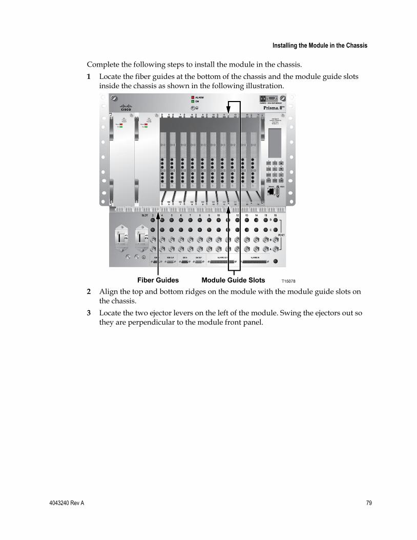
Installing the Module in the Chassis
4043240 Rev A 79
Complete the following steps to install the module in the chassis.
1 Locate the fiber guides at the bottom of the chassis and the module guide slots inside the chassis as shown in the following illustration.
2 Align the top and bottom ridges on the module with the module guide slots on the chassis.
3 Locate the two ejector levers on the left of the module. Swing the ejectors out so they are perpendicular to the module front panel.
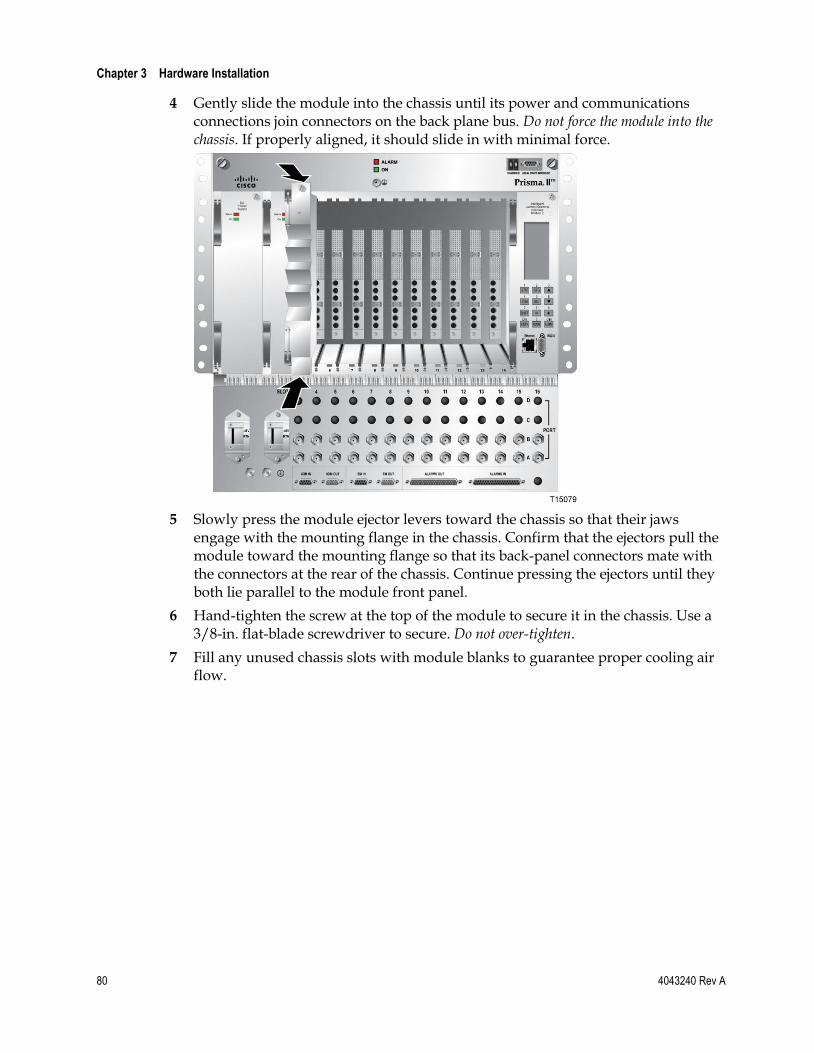
Chapter 3 Hardware Installation
80 4043240 Rev A
4 Gently slide the module into the chassis until its power and communications connections join connectors on the back plane bus. Do not force the module into the chassis. If properly aligned, it should slide in with minimal force.
5 Slowly press the module ejector levers toward the chassis so that their jaws engage with the mounting flange in the chassis. Confirm that the ejectors pull the module toward the mounting flange so that its back-panel connectors mate with the connectors at the rear of the chassis. Continue pressing the ejectors until they both lie parallel to the module front panel.
6 Hand-tighten the screw at the top of the module to secure it in the chassis. Use a 3/8-in. flat-blade screwdriver to secure. Do not over-tighten.
7 Fill any unused chassis slots with module blanks to guarantee proper cooling air flow.
Cleaning Optical Connectors
4043240 Rev A 81
Cleaning Optical Connectors
CAUTION:
Proper operation of this equipment requires clean optical fibers. Dirty fibers will adversely affect performance. Proper cleaning is imperative.
The proper procedure for cleaning optical connectors depends on the connector type. The following describes general instructions for fiber optic cleaning. Use your company's established procedures, if any, but also consider the following.
Cleaning fiber optic connectors can help prevent interconnect problems and aid system performance. When optical connectors are disconnected or reconnected, the fiber surface can become dirty or scratched, reducing system performance.
Inspect connectors prior to mating, clean as needed, and then remove all residue. Inspect connectors after cleaning to confirm that they are clean and undamaged.
Recommended Equipment
CLETOP or OPTIPOP ferrule cleaner (for specific connector type)
Compressed air (also called “canned air”)
Lint-free wipes moistened with optical-grade (99%) isopropyl alcohol
Bulkhead swabs (for specific connector type)
Optical connector scope with appropriate adaptor
Tips for Optimal Fiber Optic Connector Performance
Do not connect or disconnect optical connectors with optical power present.
Always use compressed air before cleaning the fiber optic connectors and when cleaning connector end caps.
Always install or leave end caps on connectors when they are not in use.
If you have any degraded signal problems, clean the fiber optic connector.
Advance a clean portion of the ferrule cleaner reel for each cleaning.
Turn off optical power before making or breaking optical connections to avoid microscopic damage to fiber mating surfaces.

Chapter 3 Hardware Installation
82 4043240 Rev A
To Clean Optical Connectors
Warning:
Avoid personal injury! Use of controls, adjustments, or procedures other than those specified herein may result in hazardous radiation exposure.
Avoid personal injury! The laser light source on this equipment (if a transmitter) or the fiber cables connected to this equipment emit invisible laser radiation.
Avoid personal injury! Viewing the laser output (if a transmitter) or fiber cable with optical instruments (such as eye loupes, magnifiers, or microscopes) may pose an eye hazard.
Do not apply power to this equipment if the fiber is unmated or unterminated.
Do not stare into an unmated fiber or at any mirror-like surface that could reflect light emitted from an unterminated fiber.
Use safety-approved optical fiber cable to maintain compliance with applicable laser safety requirements.
Important: Ensure that no optical power is present prior to this procedure.
1 Turn optical power off to the connector.
2 Using an optical connector scope, inspect the connector for scratches, burns, or other signs of damage.
Note: If the connector is damaged, replace the jumper.
3 If the connector requires cleaning, swipe it across the face of the appropriate ferrule cleaner several times. This will remove dust and some films.
Note: You may hear a slight "squeak" while cleaning the connector, indicating that it is clean.
4 Inspect the connector again. If the connector requires further cleaning, clean it using 99% isopropyl alcohol and a lint-free wipe.
5 Swipe the connector across the face of the appropriate ferrule cleaner several more times to remove any film left by the alcohol.
6 Repeat all the steps above as needed until the connector is clean.

Connecting Optical Cables
4043240 Rev A 83
Connecting Optical Cables Important:
Make all connections with the optical power off. This will reduce the risk of damage to fiber-optic connectors.
Clean the optical connectors as needed before making optical connections. See Cleaning Optical Connectors (on page 81) for instructions.
Note: Observe laser safety precautions. Refer to Laser Safety (on page xxv) for further information.
To Connect Optical Cables
CAUTION:
High power density exists on fiber when optical power is present. To avoid microscopic damage to fiber mating surfaces, turn off optical power or reduce power below 15 dBm before making or breaking optical connections.
Complete the following steps for each optical cable connection to be made and on every module to be installed.
1 Clean the end of the fiber to be connected as described in Cleaning Optical Connectors (on page 81).
2 Connect the optical cable to the module connector.
3 Route the cable to the appropriate destination.
4 Clean the remaining cable end, and then connect the cable to the mating module connector.
Note: Remember to observe minimum bend radius and other accepted handling practices when working with fiber-optic cables.
5 After cable installation is complete, return the module control settings to their original states.

Chapter 3 Hardware Installation
84 4043240 Rev A
Connecting RF Cables The chassis connector interface panel can have one or more RF connectors, labeled A through D, for each application module slot. Each set of RF connectors is numbered 2-16 to show its corresponding slot number.
Note: The application module installed in each chassis slot determines whether and how the two RF channels are used. See the appropriate application module documentation for further information.
To Connect RF Cables
Complete the following steps for each RF cable connection to be made.
1 Connect the RF cable to the appropriate connector on the connector interface panel.
2 Route the cable to the appropriate destination.

4043240 Rev A 85
Introduction
This chapter provides instructions for configuring the chassis and application modules for remote management.
There are several different ways to configure the equipment. This chapter presents one approach for configuration.
Refer to Prisma II Permitted CLI Commands (on page 371) for a complete list of CLI commands.
For further information on configuration using the CLI or ICIM Web Interface, see the appropriate configuration guide.
4 Chapter 4 Equipment Configuration
In This Chapter
HyperTerminal Session Setup ............................................................. 86
CLI Parameters ...................................................................................... 90
Telnet Session ........................................................................................ 94
SNMP Parameters ................................................................................. 96
Using the ICIM Web Interface ............................................................ 97
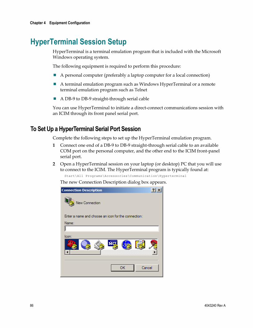
Chapter 4 Equipment Configuration
86 4043240 Rev A
HyperTerminal Session Setup HyperTerminal is a terminal emulation program that is included with the Microsoft Windows operating system.
The following equipment is required to perform this procedure:
A personal computer (preferably a laptop computer for a local connection)
A terminal emulation program such as Windows HyperTerminal or a remote terminal emulation program such as Telnet
A DB-9 to DB-9 straight-through serial cable
You can use HyperTerminal to initiate a direct-connect communications session with an ICIM through its front panel serial port.
To Set Up a HyperTerminal Serial Port Session
Complete the following steps to set up the HyperTerminal emulation program.
1 Connect one end of a DB-9 to DB-9 straight-through serial cable to an available COM port on the personal computer, and the other end to the ICIM front-panel serial port.
2 Open a HyperTerminal session on your laptop (or desktop) PC that you will use to connect to the ICIM. The HyperTerminal program is typically found at:
Start\All Programs\Accessories\Communication\Hyperterminal
The new Connection Description dialog box appears.

HyperTerminal Session Setup
4043240 Rev A 87
3 Type in a name for the connection, select an icon of your choice, and click OK. The Connect To dialog box appears.
4 In the Connect Using field, click the drop-down arrow and select the serial port that you will use for the connection, and then click OK. The COM Properties dialog box appears.
Note: For most applications, the serial port is COM1 or COM2.
5 Set the following port setting in the COM Properties dialog box.

Chapter 4 Equipment Configuration
88 4043240 Rev A
6 Click OK. The HyperTerminal main program window appears.
7 On the File menu, click Save to save the settings.
8 Wait for the ICIM boot to finish. Once finished, press Enter to display the ICIM login prompt:
Scientific-Atlanta Intelligent Communications Interface Module (ICIM) --------------------- W A R N I N G --------------------- Unauthorized or improper use of this system may result in administrative disciplinary action and civil or criminal penalties. By continuing to use this system you indicate your awareness of and consent to these terms and conditions of use. LOG OFF IMMEDIATELY if you do not agree to the conditions stated in this warning. login:
9 Log in using the default username Administrat0r and the default password AdminPassw0rd. Note the 0 (zero) character in each string.
Scientific-Atlanta Intelligent Communications Interface Module (ICIM) login: Administrat0r Password: AdminPassw0rd
Successful login will return the following prompt: login: Administrat0r Password: User Administrat0r logged in successfully on 11/13/06 at 15:25:35 Previous successful login was on 11/13/06 at 15:22:16 There were no failed attempts to login with this user id previously CLI>
10 Enter the ICIM submenu by typing icim at the CLI> prompt.
CLI> icim
Successful entry into the ICIM menu tree will return the following prompt: ICIM>

HyperTerminal Session Setup
4043240 Rev A 89
11 Configure the shelf (chassis) IP address, subnet mask, gateway, and clock using the following commands:
set ip xxx.xxx.xxx.xxx set subnet xxx.xxx.xxx.xxx set gateway xxx.xxx.xxx.xxx set clock "month/day/year hour:minute:second"
Note:
Be sure to include the quote symbols, e.g., set clock "3/15/2006 13:09:51".
Clock time is in the 24-hour format.
12 If desired, enable IPsec (disabled by default) by following the instructions in Setting Up IPsec (on page 315).
13 To enable these changes, reboot the ICIM as follows: ICIM> reboot
14 After the ICIM reboots, repeat the login steps described above to return to the ICIM command prompt. Then use the show command to verify each of the above changes, as follows: show ip show subnet show gateway show clock
15 Type logout, and then press Enter to exit the session.
16 Remove the serial cable. It is no longer required.
Important:
For Telnet operation, the computer you are using must have a network connection through which it can reach the ICIM at its IP address.
No more than four Telnet sessions are allowed at one time.
CAUTION:
Always use the Logout command to close a serial port or Telnet CLI session. Closing a serial port session without issuing the Logout command leaves the session open for a possible future connection. This may allow unauthorized access by a new user if the previous user had a higher authorization privilege level.

Chapter 4 Equipment Configuration
90 4043240 Rev A
CLI Parameters Additional parameters may be set as needed from the command line interface (CLI) for each application module installed.
Refer to Prisma II Permitted CLI Commands (on page 371) and the appropriate configuration guide for information and additional instructions on available commands and using the CLI.
Following are examples of parameters available through the CLI.
Login 1 Log in using the default username Administrat0r and the default password
AdminPassw0rd. Note the 0 (zero) character in each string.
Scientific-Atlanta Intelligent Communications Interface Module (ICIM) login: Administrat0r Password: AdminPassw0rd
Successful login will return the following prompt: login: Administrat0r Password: User Administrat0r logged in successfully on 11/13/06 at 15:25:35 Previous successful login was on 11/13/06 at 15:22:16 There were no failed attempts to login with this user id previously CLI>
2 Enter the ICIM submenu by typing icim at the CLI> prompt.
CLI> icim
Successful entry into the ICIM menu tree will return the following prompt: ICIM>
3 Configure the shelf (chassis) IP address, subnet mask, gateway, and clock using the following commands: set ip xxx.xxx.xxx.xxx set subnet xxx.xxx.xxx.xxx set gateway xxx.xxx.xxx.xxx set clock "month/day/year hour:minute:second"
Note:
Be sure to include the quote symbols, e.g., set clock "3/15/2006 13:09:51".
Clock time is in the 24-hour format.
4 If desired, enable IPsec (disabled by default) by following the instructions in Setting Up IPsec (on page 315).
5 To enable these changes, reboot the ICIM as follows:
ICIM> reboot

CLI Parameters
4043240 Rev A 91
6 After the ICIM reboots, repeat the login steps described above to return to the ICIM command prompt. Then use the show command to verify each of the above changes, as follows:
show ip show subnet show gateway show clock
7 Type logout, and then press Enter to exit the session.
8 Remove the serial cable. It is no longer required.
Important:
For Telnet operation, the computer you are using must have a network connection through which it can reach the ICIM at its IP address.
No more than four Telnet sessions are allowed at one time.
CAUTION:
Always use the Logout command to close a serial port or Telnet CLI session. Closing a serial port session without issuing the Logout command leaves the session open for a possible future connection. This may allow unauthorized access by a new user if the previous user had a higher authorization privilege level.
To Set the Clock
From the CLI command prompt, switch to ICIM command mode and set the date and time for the ICIM, as shown below.
CLI> icim
ICIM> set clock "10/10/2005 15:50:00" MM-DD-YYYY HH:mm:ss 10-10-2005 15:50:00
Mon, 10 Oct 2005 15:50:00 EST
SUCCESS!
To Set Additional Users for ICIM Access
Refer to the appropriate configuration guide for CLI and ICIM Web Interface login settings information.
Note: It is strongly recommended that a new administrator login be created and that the default administrator login be removed.
The table below lists the ICIM mode CLI commands for setting user login parameters.

Chapter 4 Equipment Configuration
92 4043240 Rev A
Commands Description
ICIM > show user Shows all users
ICIM > user change password [user name] Changes user password
ICIM > user add [user name] [access level] enable Adds a user
ICIM > user delete [user name] Deletes a user
Note: User names and passwords must be 6 to 14 characters long, and must include at least 1 number.
To Set and Verify SNMP Community Strings
From the CLI command prompt, switch to ICIM command mode and define SNMP Read, Write, and Trap Community strings, as shown below.
CLI> icim
ICIM> set commwrite “myCommWriteString” NOTE: This change will not fully take effect until the ICIM is restarted. Until that time, some operations will not perform as expected.
SUCCESS!
ICIM> set commread “myCommReadString” NOTE: This change will not fully take effect until the ICIM is restarted. Until that time, some operations will not perform as expected.
SUCCESS!
ICIM> set commtrap “myCommTrapString” NOTE: This change will not fully take effect until the ICIM is restarted. Until that time, some operations will not perform as expected.
SUCCESS!
You can then verify the community string settings, as follows.
ICIM> info commread commwrite commtrap
COMMREAD COMMWRITE COMMTRAP
myCommReadString myCommWriteString myCommTrapString
SUCCESS!
ICIM>

CLI Parameters
4043240 Rev A 93
Note:
It is strongly recommended that you restart the ICIM after changing any of the community strings. Otherwise, some operations will continue to work normally, while others will appear to fail.
It is strongly recommended that you create new SNMP community strings and remove the default SNMP community strings. Default SNMP community string values are listed below.
SNMP Community String Default Value
Read Community public
Write Community private
Trap Community SNMP_traps

Chapter 4 Equipment Configuration
94 4043240 Rev A
Telnet Session Telnet is a remote terminal emulation program included with the Microsoft Windows operating system. In the absence of a network management system, you can use Telnet to initiate a remote communications session with an ICIM2 and configure the equipment in the domain using CLI commands.
Important:
For Telnet operation, the computer you are using must have a network connection through which it can reach the ICIM at its IP address.
No more than four Telnet sessions are allowed at one time.
CAUTION:
Always use the Logout command to close a serial port or Telnet CLI session. Closing a serial port session without issuing the Logout command leaves the session open for a possible future connection. This may allow unauthorized access by a new user if the previous user had a higher authorization privilege level.
To Set Up a Telnet CLI Session
Complete the following steps to initiate a CLI session with the ICIM using Telnet.
Important:
The ICIM must have an IP address assigned before performing this procedure.
When using IPsec, the ICIM and all computers with which it communicates must be set up for IPsec. For detailed instructions, see Setting Up IPsec (on page 315).
1 Open a DOS window on the PC that will connect to the ICIM.

Telnet Session
4043240 Rev A 95
2 At the DOS command prompt, type: telnet <IP address>
where <IP address> is the IP address of the ICIM. The session starts and the Telnet login: prompt appears.
3 At the login: prompt, type Administrat0r (note the zero character in the string), and then press Enter.
4 At the Password: prompt, type AdminPassw0rd (note the zero character in the string), and then press Enter. The CLI> command prompt appears.
Chapter 4 Equipment Configuration
96 4043240 Rev A
SNMP Parameters Trap settings and other parameters can be set in one of several ways:
Using Simple Network Management Protocol (SNMP) commands. Refer to SNMP Management (on page 193) for details on accessing the ICIM MIB tables.
Using the Command Line Interface (CLI) Traps Enable command. Refer to the appropriate configuration guide for details on using the Traps Enable command.
Using the ICIM Web Interface, which requires no knowledge of SNMP or CLI. For further information, refer to the appropriate configuration guide.
Once this is accomplished, changes can be made to the ICIM Trap tables, of which there are 10 entries (one for each destination IP address).
Following are the objects in the p2TrapRecvEntry table that should be set.
MIB Object Value
p2TrapRecvEnable 1-disabled; 2-enabled
p2TrapRecvAddr IP address of trap receiver
p2TrapRecvTelcoAlarm 1-disabled; 2-enabled

Using the ICIM Web Interface
4043240 Rev A 97
Using the ICIM Web Interface You can also use the ICIM Web Interface to configure equipment in the ICIM domain. The ICIM Web Interface is menu-based and requires no knowledge of CLI or SNMP commands.
Note: The ICIM Ethernet port must be connected to an IP-based Ethernet network, or directory to a PC with similar subnet address.
This section describes the steps for logging in and out of the Web Interface. For additional details, see the appropriate configuration guide.
Login Settings
To use the Web Interface, you must enter a valid user name and password. The default user name and password are given below.
User name: Administrat0r
Password: AdminPassw0rd
Note:
Both the default user name and the default password have a zero (0) in place of the expected "o" character.
For security reasons, it is recommended that the default user name be changed immediately. For additional information, see User Management in the appropriate system guide.
To Change Login Defaults
Complete the following steps to change the default user name and password.
1 Add a new user having Admin Level privileges.
2 Log out of the default user account, and then log back in using the new Admin level account.
3 Locate the original default user name in the list of users. Click the Delete button beside the default user name to delete it from the list.
Important: Note your new login defaults for future reference. Failure to remember your new user ID and password may result in being locked out of the ICIM permanently. You cannot revert to the default user name and password once they are deleted.

Chapter 4 Equipment Configuration
98 4043240 Rev A
To Log In
Complete the following steps to log into the ICIM.
1 Confirm that your web browser is set up as described in the appropriate configuration guide.
2 Obtain the actual IP address of the Web Interface Login page from your system administrator.
3 Open your web browser and type the IP address of the ICIM (e.g., 172.8.50.151) in the browser address bar.
4 Press the Enter key or click the Go button. The ICIM Login page appears as shown below.

Using the ICIM Web Interface
4043240 Rev A 99
5 Type your User name and Password in the fields provided, and then click the Login button. The ICIM Welcome page appears as shown below.
6 Use one of the following navigation methods as appropriate:
Click Next to go to the System View page. Or, wait 10 seconds to be taken to System View automatically.
Use the menu at the left of the screen to go directly to System View or to choose another page of interest.
To Log Out
Complete the following steps to log out of the Web Interface.
1 Click Logout in the main menu. The Web Interface Logout page appears as shown below.

Chapter 4 Equipment Configuration
100 4043240 Rev A
2 Close your browser window as a security precaution.
CAUTION:
Before closing the browser or tab in which the Web Interface session is running, be sure to log out of the Web Interface using the Logout link at the bottom left of the navigation pane.
If you close the browser or tab before logging out, the session will hang open for the duration of a timeout interval. This may prevent access to the ICIM through either the CLI or the Web Interface by you or other users. This may also create a breach of security by enabling unauthorized users to access the Web Interface at the previous user authorization level by opening a new browser tab.

4043240 Rev A 101
Introduction
This chapter describes the ICIM software interface for platform configuration, monitoring, and control. It also describes the ICIM LCD and keypad front-panel interface for performing these functions.
For detailed information on system parameters, see Module Parameter Descriptions (on page 395).
5 Chapter 5 ICIM Operation
In This Chapter
Platform Configuration ...................................................................... 102
Operating the ICIM2 .......................................................................... 103
Configuring for Remote Network Access ....................................... 113
Using ICIM2 with the Fan Tray ........................................................ 116
Using ICIM2 with Power Supply 1 .................................................. 121
Using ICIM2 with Power Supply 3 .................................................. 126

Chapter 5 ICIM Operation
102 4043240 Rev A
Platform Configuration
NMS Application(Optional)
NMS Platform
FTP Server
Po
wer
Su
pp
ly
& F
an
s
Op
tica
l M
od
ule
Op
tica
l M
od
ule
Configuration & Management Bus
Prisma II or Prisma II XD Chassis
Enet
Daisy Chain multiple chassis
ICIM IN/OUT Ports
Local or Remote PC
IP Network
Ethernet
Com
CLI Interface
Hyperterm SW
Local PC
[Username/passwd Protection – Multiple
Chassis]
Ethe
rnet
TP536
SA Remote SW
Downloader App
(SOUP)
LCI Port
ICIM
2/-
XD

Operating the ICIM2
4043240 Rev A 103
Operating the ICIM2 Once the ICIM2 module is installed, it runs without the aid of an operator. Unless alarms are generated or your system configuration changes, you should not need to make any adjustments to the module beyond the initial setup.
ICIM2 Illustration (Front Panel)

Chapter 5 ICIM Operation
104 4043240 Rev A
ICIM2 Front Panel Features
Part Function
LCD screen Displays the ICIM2 menus, alarms, and status information.
12-key numeric keypad
Used to navigate the ICIM2 menus.
Ethernet connector Directly connects the ICIM2 to an IP network. The ICIM2 Ethernet port is suitable for connection to intra-building wiring, non-exposed wiring or cabling only.
RS232 connector Used to connect a PC to the Prisma II Enhanced system for CLI communication and setup.
ICIM2 LCD
The ICIM2 LCD gives the operator a visual link to the ICIM2 firmware. When the ICIM2 is installed and powered up, the MAIN menu appears on the LCD.
The following illustration shows the MAIN menu.
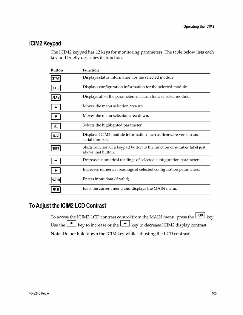
Operating the ICIM2
4043240 Rev A 105
ICIM2 Keypad
The ICIM2 keypad has 12 keys for monitoring parameters. The table below lists each key and briefly describes its function.
Button Function
Displays status information for the selected module.
Displays configuration information for the selected module.
Displays all of the parameters in alarm for a selected module.
Moves the menu selection area up.
Moves the menu selection area down.
Selects the highlighted parameter.
Displays ICIM2 module information such as firmware version and serial number.
Shifts function of a keypad button to the function or number label just above that button.
Decreases numerical readings of selected configuration parameters.
Increases numerical readings of selected configuration parameters.
Enters input data (if valid).
Exits the current menu and displays the MAIN menu.
To Adjust the ICIM2 LCD Contrast
To access the ICIM2 LCD contrast control from the MAIN menu, press the key.
Use the key to increase or the key to decrease ICIM2 display contrast.
Note: Do not hold down the ICIM key while adjusting the LCD contrast.

Chapter 5 ICIM Operation
106 4043240 Rev A
ICIM Password
The ICIM allows you to send configuration commands, change alarm thresholds, and restore factory default settings in Prisma II modules. To prevent unauthorized changes to these parameters, you have the option of using a password protection system. Password authorization only applies to configurable parameters. Status and alarm information is always available on the ICIM, regardless of password implementation.
Password Protection System
The ICIM menu options available in the password protection system are shown here.
ICIM Menu Option
Description
User Psw A user-settable password.
Created, entered, and changed by the system operator(s)
Must be exactly eight digits, using only the 0-9 number keys
Change Psw Changes an existing user password.
Disable Psw Disables the user password function.
SA Psw A service password used by factory personnel only.
Important: If you only want to monitor status and alarm data, skip the password function when it appears on the ICIM menu. You can access all module status and alarm information without a password.
However, once a user password is entered, you are required to enter it every time you want to set configurable parameters to any module controlled by that ICIM. Refer to Expired Password or Inactive Password Messages (on page 107) and To Enter the User Password (on page 107).
To Access the Password Menu
The Password menu allows you to create, enter, change, or disable the user password. It also allows service personnel to use the factory default password.
1 Press the key.
2 Use the key to scroll down until Password is highlighted.

Operating the ICIM2
4043240 Rev A 107
3 Press the key. The Password menu appears. User Psw is highlighted.
M A I N
O f f l i n e
M o d u l e s0
A l a r m s0
S c r o l l
M o d u l eS h e l fS l o t
I C I MS h e l f 7S l o t 1 5
M f g D a t a
P a s s w o r dI P S e t u p
U p d a t e A d r
I C I M
M f g D a t a
P a s s w o r d I P S e t u p
U p d a t e A d r
I C I M
U s e r P s w
S A P s w
C h a n g e P s w
D i s a b l e P s w
S h e l f 7S l o t 1 5
S h e l f 7S l o t 1 5
TP012
Expired Password or Inactive Password Messages
The entry of a valid password allows changes to system parameters for a period of 10 minutes. If more than 10 minutes has passed since your last keystroke, and you attempt to make any changes to system parameters, the menu displays Psw Expired. If, after more than 10 minutes, you attempt to disable the password the menu displays Failed, Password Not Active. If either of these messages is displayed, you are required to re-enter the password. To re-enter the password, follow the procedure in To Enter the User Password (on page 107).
To Enter the User Password
If you wish to use the user password feature, you must create and enter a password of exactly eight digits using only the 0-9 number keys. The password remains active for 10 minutes after your last keystroke. If you want to change configuration parameters after more than 10 minutes, you are required to re-enter your password.
1 Access the Password menu as shown earlier in To Access the Password Menu (on page 106).
2 Press the key.
Result: The user password menu appears.
3 When User Psw/Shift Off appears, press the key to display Shift On, and then enter the eight digits of your password, using the 0-9 number keys.
If at any time you input a digit that is incorrect or you wish to change a digit, use
the CAN (Cancel) function by pressing the key to delete that digit.

Chapter 5 ICIM Operation
108 4043240 Rev A
4 Press the key to enter the password. Results:
The ICIM updates the display to show if your password entry was accepted or rejected.
If the entry was accepted, you are able to return to the MAIN menu.
5 If the password you entered is rejected, press the key to return to the password menu, then re-enter an 8-digit password using only the 0-9 number
keys. Press the key to input the password.
Reasons for a password to be rejected include:
Entering more than eight digits for the password
Pressing keys other than the 0-9 number keys
Entering an incorrect password if a valid password has been entered
I C I M I C I MS h e l f 0S l o t 1 5
I C I M I C I M
U s e r P s w1 2 3 4 5 6 7 8
S h e l f 0S l o t 1 5
S h e l f 0S l o t 1 5
TP013
S h e l f 0S l o t 1 5
U s e r P s w1 2 3 4 * * * *
U s e r P s w* * * * * * * *
U s e r P s w
S h i f t O f f S h i f t O n
R e j e c t e d
S h i f t O f f
A c c e p t e d
S h i f t O f f
To Change the User Password
If a user password has been entered, it may be changed. However, the current password must be active prior to changing it. If the current password has expired (more than 10 minutes have passed since your last keystroke), you must re-enter the current password before changing to a new one.
1 Access the Password menu as shown in the procedure To Access the Password Menu (on page 106).
2 Use the key to scroll down until Change Psw is highlighted.
3 Press the key to select Change Psw.
4 When Change Psw /Shift Off appears, press the key to display Shift On, and then enter the eight digits of your new password, using the 0-9 number keys.
If at any time you input a digit that is incorrect or wish to change a digit, use the
CAN (Cancel) function by pressing the key to delete that digit.

Operating the ICIM2
4043240 Rev A 109
5 Press the key to input the new password. As a result:
The ICIM updates the display to show if your password entry was accepted or rejected.
If the entry was accepted, you are able to return to the MAIN menu.
6 If the new password you entered is rejected, press the key to return to the password entry menu. Clear all digits using the CAN (Cancel) function, then re-
enter an 8-digit password using only the 0-9 number keys. Press the key to input the password.
I C I M I C I MS h e l f 7S l o t 1 5
I C I M I C I M
C h a n g e P s w8 7 6 5 4 3 2 1
S h e l f 7S l o t 1 5
S h e l f 7S l o t 1 5
TP014
S h e l f 7S l o t 1 5
C h a n g e P s w* * * * * * * *
C h a n g e P s wU s e r P s w
D i s a b l eP s w
S h i f t O f f S h i f t O n S h i f t O n
C h a n g e P s w
S A P s w
To Disable the User Password using ICIM
If a user password has been entered, you may disable it at any time. However, the current password must be active prior to disabling it. If the current password has expired (more than 10 minutes have passed since your last keystroke), you must re-enter the current password before disabling it.
1 Press the key.
2 Use the key to scroll down until Password is highlighted.
3 Press the key.
4 Use the key to scroll down until Disable Psw is highlighted.
5 Press the key to select Disable Psw.
6 If the current password is active, the menu displays Password Is Now Disabled. You can now make changes to parameters without any password.

Chapter 5 ICIM Operation
110 4043240 Rev A
7 If the current password has expired (more than 10 minutes have passed since your last keystroke), the menu displays Failed, Password Not Active. If this occurs, you must re-enter the current password and repeat this procedure.
I C I M I C I MS h e l f 7S l o t 1 5
I C I MS h e l f 7S l o t 1 5
TP015
S h e l f 7S l o t 1 5
E n t e r P s w8 7 6 5 4 3 2 1
E n t e r P s w8 7 6 5 * * * *
U s e r P s w
D i s a b l eP s w
P a s s w o r dI s N o w
D i s a b l e d
S h i f t O f f
F a i l e d ,P a s s w o r d
N o t A c t i v e
S h i f t O f f
C h a n g e P s w
S A P s w
Prisma II MAIN Menu and ICIM Menu Structure
Pressing the key initiates the MAIN menu. Pressing the key initiates the ICIM menu. The MAIN and ICIM menu structures are shown below.
Note: As shown above, there are two possible ICIM menu structures: one for the MSO software configuration and another for MSO1.

Operating the ICIM2
4043240 Rev A 111
MAIN Menu
A few seconds after power-up, the MAIN menu (shown below) appears. Press the
key to select the specific option.
Display Description
Offline Indicates communication status between the ICIM2 and TNCS.
Modules Indicates the number of modules in the ICIM2 domain.
Alarms Displays the number of modules that are in alarm. Selecting this option allows scrolling through all modules in alarm condition.
Scroll Allows scrolling through all modules in the ICIM2 domain.
Module Shelf Slot
Allows selection of a specific module in the ICIM2 domain.
ICIM Menu
To display the ICIM menu, press the key. The ICIM menu (shown below)
appears. Press the key to select the specific option.
Display Description
Shelf Slot
Displays the location of the ICIM. Shelf = Chassis ID number on the front of the chassis. Slot = Slot number within the chassis.
Mfg Data Displays manufacturing data about the ICIM.
Password * Lets you enter, change, or disable a system password from the ICIM keypad. See ICIM Password (Keypad Interface) (on page 130).
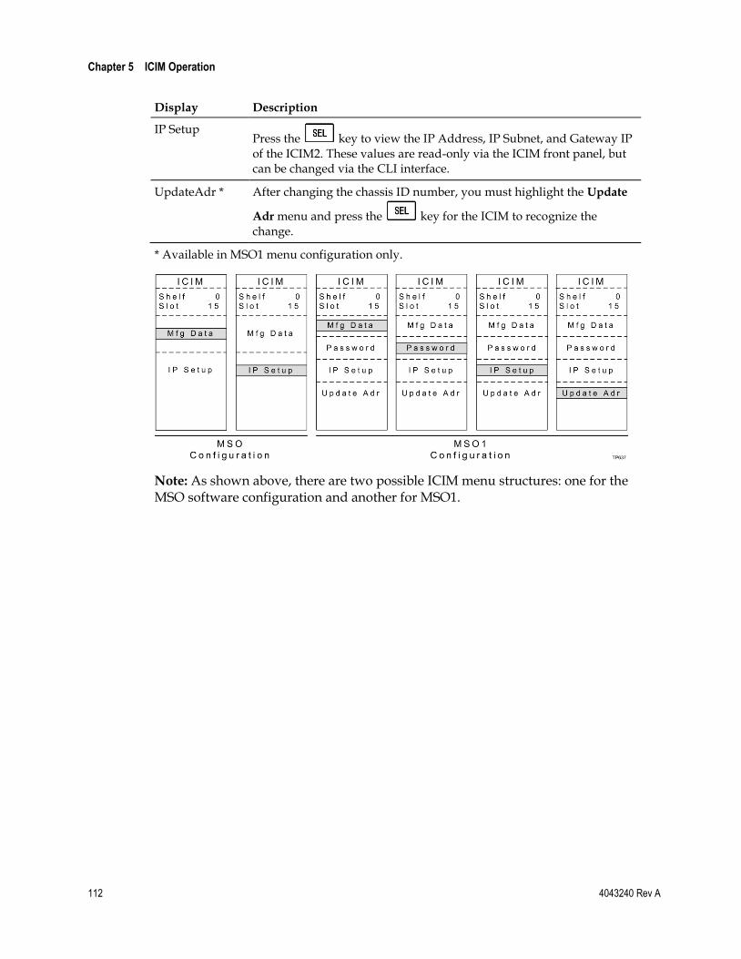
Chapter 5 ICIM Operation
112 4043240 Rev A
Display Description
IP Setup Press the key to view the IP Address, IP Subnet, and Gateway IP of the ICIM2. These values are read-only via the ICIM front panel, but can be changed via the CLI interface.
UpdateAdr * After changing the chassis ID number, you must highlight the Update
Adr menu and press the key for the ICIM to recognize the change.
* Available in MSO1 menu configuration only.
Note: As shown above, there are two possible ICIM menu structures: one for the MSO software configuration and another for MSO1.
Configuring for Remote Network Access
4043240 Rev A 113
Configuring for Remote Network Access The ICIM2 has an IP Setup menu that lets you enter an IP address, IP subnet, and gateway IP to configure the ICIM2 for remote monitoring and control by an SNMP network management system (NMS).
This section explains the use of the IP Setup menu in configuring the ICIM2 for SNMP. For additional information on SNMP, see SNMP Management (on page 193).
Preliminary Steps for SNMP
Take the following initial steps when implementing SNMP.
Confirm that the NMS is installed behind a firewall to prevent access to and tampering with the ICIM2 by unauthorized persons with an SNMP manager.
Make the SNMP connection through the Ethernet port on the front of the ICIM2. Use a 10BaseT cable with an RJ-45 connector.
Monitor the ICIM2 response time for possible slow response to both SNMP control and front-panel input, especially during periods of heavy network traffic. If required, reduce the update rate of the SNMP manager.
To Configure the ICIM2 for SNMP
Complete the following steps to set up ICIM2 IP configuration parameters.
1 Press the key. The ICIM menu appears.
2 Select the Password menu and enter the User Password. The ICIM2 will now permit configuration changes for 10 minutes.
3 Press the key. The ICIM menu appears.
4 Use the key to move the highlight down to the IP Setup menu item.

Chapter 5 ICIM Operation
114 4043240 Rev A
5 Press the key. The IP Setup menu appears, as shown in the following illustration.
I C I M
TP534
S h e l f 7S l o t 1 5
I P A d d r e s s1 7 2 . 1 8 . 9 . 2 2 7
I P S u b n e t2 5 5 . 2 5 5 . 2 5 5 . 0
G a t e w a y I P1 7 2 . 1 8 . 9 . 2 5 4
6 Use the and keys to scroll to and highlight the IP address configuration parameter.
7 Press the key. The Adjust menu for the IP address parameter appears as shown in the following illustration.
I C I M
TP535
S h e l f 7S l o t 1 5
A d j u s tI P A d d r e s s1 7 2 . 1 8 . 9 . 2 2 7
8 Change each segment of the IP address to the desired value. You can do this in one of two ways:

Configuring for Remote Network Access
4043240 Rev A 115
a Use the and keys to increase or decrease the currently
highlighted address segment. When finished, press the key to accept your entry and move to the next address segment.
b Press the key to change to numeric entry mode, and then type the desired value for the highlighted address segment. When typing the IP address, the cursor moves to the next address segment to the right automatically after you enter the last digit. Note, however, that you must use leading zeros as needed to enter three digits per address segment.
9 After changing all address segments, press the key to return to the IP Setup menu.
10 Repeat Steps 6-9 above as needed to change the IP subnet and gateway IP address.
11 Restart the ICIM2 as described next.
To Restart the ICIM2
Complete the following steps to restart the ICIM2.
1 Fully loosen the captive screw holding the ICIM2 in the chassis.
2 Unlock the top and bottom ejector levers near the left side of the ICIM2.
3 Pull the ejector levers out and away from the front panel to disconnect the ICIM2 from the chassis backplane connector.
4 Pull the ICIM2 at least 1.5 inches (3.81 cm) out from the front of the chassis to ensure that it is fully separated from the chassis backplane connector.
5 Reinsert the ICIM2 into the chassis until the ejector levers insert into their respective slots in the chassis.
6 Push the ejector levers in and flat against the ICIM2 front panel to reconnect the ICIM2 to the backplane connector until the ejector levers lock in place.
7 Fully tighten in the captive screw to secure the ICIM2 in the chassis.

Chapter 5 ICIM Operation
116 4043240 Rev A
Using ICIM2 with the Fan Tray
Fan Tray Menu Structure
From the MAIN or SCROLL menus, you can navigate to the MODULE menu. From
the MODULE menu, press the or key to display the desired parameter menu.
Note: All parameters may be monitored in the STATUS menu. Because the ICIM2 front panel is read-only for all fan tray parameters, no instructions are provided here for navigating the CONFIG menu.
ALARMSFansOk
ChasTemp
TP639
Mfg. DataModule NameModule Type
Serial #Date Code
Sw VerIn Service Hrs
Spec Data
Restore Factory
Defaults *
MAIN or SCROLL
Menu
MAIN or SCROLL
Menu
MAIN or SCROLL
Menu
MODULEMenu
MODULEMenu
MODULEMenu
STATKey
CONFIGKey
ALARMSKey
CONFIGNo ConfigVariables
STATUSChas+24VChas+5VChas-5V
ChasTempFansOnPs1InstPs3Inst
* MSO1 only
To Check Operating Status
Using the ICIM2, you can check the status of all operating parameters of this module. All status information is displayed on the ICIM2 LCD.
Complete the following steps to monitor operating parameters.
1 At the MAIN menu, press the key to highlight the Shelf and Slot fields.
2 Press the key to address the Shelf number. Then press the key or the
key to scroll to the number of the desired shelf.
3 Press the key. The Slot field is highlighted.
4 Press the key or the key to scroll to the number of the desired slot.
5 Press the key. The ICIM2 displays the MODULE menu.
6 Press the key.
7 Press the key or the key to scroll through the monitored parameters until you find the parameter of interest.
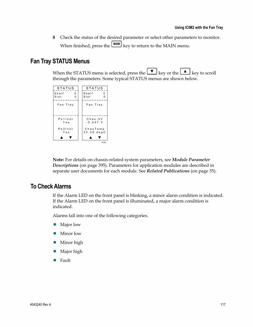
Using ICIM2 with the Fan Tray
4043240 Rev A 117
8 Check the status of the desired parameter or select other parameters to monitor.
When finished, press the key to return to the MAIN menu.
Fan Tray STATUS Menus
When the STATUS menu is selected, press the key or the key to scroll through the parameters. Some typical STATUS menus are shown below.
S T A T U S
F a n T r a y
P s 1 I n s t Y e s
P s 3 I n s t Y e s
S T A T U SS h e l f 0S l o t 0
TP383
S h e l f 0S l o t 0
F a n T r a y
C h a s - 5 V- 5 . 0 4 7 V
C h a s T e m p3 2 . 2 8 d e g C
Note: For details on chassis-related system parameters, see Module Parameter Descriptions (on page 395). Parameters for application modules are described in separate user documents for each module. See Related Publications (on page 35).
To Check Alarms
If the Alarm LED on the front panel is blinking, a minor alarm condition is indicated. If the Alarm LED on the front panel is illuminated, a major alarm condition is indicated.
Alarms fall into one of the following categories.
Major low
Minor low
Minor high
Major high
Fault

Chapter 5 ICIM Operation
118 4043240 Rev A
Complete the following steps to check alarm conditions.
1 From the MAIN menu, press the key to highlight the Shelf and Slot fields.
2 Press the key to address the Shelf number. Then press the key or the
key to scroll to the number of the desired shelf.
3 Press the key. The Slot field is highlighted.
4 Press the key or the key to scroll to the number of the desired slot.
5 Press the key. The ICIM2 displays the MODULE menu.
6 Press the key. Module alarm conditions display.
7 Use the key or the key to scroll through alarm conditions until the desired alarm is displayed.
8 Monitor the alarm condition(s). Take appropriate action. Verify that all settings and thresholds relating to the alarm indication are set correctly to rule out an unintended alarm.
9 When finished, press the key to return to the MAIN menu.
Fan Tray ALARMS Menus
After selecting the ALARMS menu function, press the key or the key to scroll through the modules in alarm. Some typical ALARMS menus are shown below.
A L A R M S
F a n T r a y
F a n s O k F a u l t
C h a s T e m pM a j o r L o w
A L A R M SS h e l f 0S l o t 0
TP165
S h e l f 0S l o t 0
F a n T r a y
Note: For details on chassis-related system parameters, see Module Parameter Descriptions (on page 395). Parameters for application modules are described in separate user documents for each module. See Related Publications (on page 35).

Using ICIM2 with the Fan Tray
4043240 Rev A 119
To Check Fan Tray Manufacturing Data
The Manufacturing Data information can be displayed on the ICIM menu.
Complete the following steps to access the module manufacturing data.
1 From the MAIN menu, press the key to highlight the Shelf and Slot fields.
2 Press the key to address the Shelf number. Then press the key or the
key to scroll to the number of the desired shelf.
3 Press the key. The Slot field is highlighted.
4 Press the key or the key to scroll to the number of the desired slot.
5 Press the key. The MODULE menu for this module will be selected, as
shown on the left below. Press the key to enter the start of the MFG. DATA screens, as shown on the right below.
6 The and keys allow you to scroll through the manufacturing data.
M O D U L ES h e l f 0S l o t 0
TP545
F a n T r a y
A l a r m s1
M f g . D a t a
M F G . D A T AS h e l f 0S l o t 0
F a n T r a y
M o d u l e T y p e
5 0 0 0

Chapter 5 ICIM Operation
120 4043240 Rev A
Fan Tray MFG. DATA Menus
When the MFG. DATA menu is selected, the key or the key allows you to scroll through the manufacturing parameters specific to this module. Sample MFG. DATA menus are shown below.
M F G . D A T A
F a n T r a y
M o d u l eT y p e
5 0 0 0
M F G . D A T AS h e l f 0S l o t 0
M F G . D A T A M F G . D A T AS h e l f 0S l o t 0
F a n T r a y
S e r i a l #~ A A N J Y Z D
D a t e C o d eJ 0 4
S h e l f 0S l o t 0
S h e l f 0S l o t 0
F a n T r a y F a n T r a y
* M S O 1 O n l y
M F G . D A T A
TP642
S h e l f 0S l o t 0
F a n T r a y
S p e c D a t a
R e s t o r e F a c t o r y
D e f a u l t s *
I n S e r v i c eH o u r s
4 5
S W V e r1 . 0 1 . 0 8
S c r i p t V e rX
Note: For details on chassis-related system parameters, see Module Parameter Descriptions (on page 395). Parameters for application modules are described in separate user documents for each module. See Related Publications (on page 35).

Using ICIM2 with Power Supply 1
4043240 Rev A 121
Using ICIM2 with Power Supply 1
Power Supply 1 Menu Structure
From the MAIN or SCROLL menus, you can navigate to the MODULE menu. From
the MODULE menu, press the or key to display the desired parameter menu.
Note: All parameters may be monitored in the STATUS menu. Because the ICIM2 front panel is read-only for all power supply 1 parameters, no instructions are provided here for navigating the CONFIG menu.
Mfg. DataModule NameModule Type
Serial #Date Code
Sw VerIn Service Hrs
Spec Data
Restore Factory
Defaults *
ALARMSPs1PwrInPs1+24
Ps1+5VDCPs1-5VDC
TP640
MAIN or SCROLL
Menu
MAIN or SCROLL
Menu
MAIN or SCROLL
Menu
MODULEMenu
MODULEMenu
MODULEMenu
STATKey
CONFIGKey
ALARMSKey
CONFIGNo ConfigVariables
STATUSPs1+24VPs1+5VPs1-5V
Ps1Temp
* MSO1 only
Because the power supplies are double-wide modules, the ICIM2 addresses the power supply installed in slots 1 and 2 as Ps1. Ps3 refers to the power supply installed in slots 3 and 4.
To Check Operating Status
Using the ICIM2, you can check the status of all operating parameters of this module. All status information is displayed on the ICIM2 LCD.
Complete the following steps to monitor operating parameters.
1 At the MAIN menu, press the key to highlight the Shelf and Slot fields.
2 Press the key to address the Shelf number. Then press the key or the
key to scroll to the number of the desired shelf.
3 Press the key. The Slot field is highlighted.
4 Press the key or the key to scroll to the number of the desired slot.
5 Press the key. The ICIM2 displays the MODULE menu.
6 Press the key.

Chapter 5 ICIM Operation
122 4043240 Rev A
7 Press the key or the key to scroll through the monitored parameters until you find the parameter of interest.
8 Check the status of the desired parameter or select other parameters to monitor.
When finished, press the key to return to the MAIN menu.
Power Supply 1 STATUS Menus
When the STATUS menu is selected, press the key or the key to scroll through the parameters. Some typical STATUS menus are shown below.
S T A T U S
P o w e r S u p p l y 1
P s 1 + 2 4 V2 4 . 5 8 V
S T A T U SS h e l f 0S l o t 1
S T A T U S
TP163
S h e l f 0S l o t 1
P o w e r S u p p l y 1
P s 1 + 5 V5 . 4 0 5 V
P s 1 - 5 V- 5 . 6 1 2 V
S h e l f 0S l o t 1
P o w e r S u p p l y 1
P s 1 T e m p2 8 . 5 2 d e g C
Note: For details on chassis-related system parameters, see Module Parameter Descriptions (on page 395). Parameters for application modules are described in separate user documents for each module. See Related Publications (on page 35).
To Check Alarms
If the Alarm LED on the front panel is blinking, a minor alarm condition is indicated. If the Alarm LED on the front panel is illuminated, a major alarm condition is indicated.
Alarms fall into one of the following categories.
Major low
Minor low
Minor high
Major high
Fault

Using ICIM2 with Power Supply 1
4043240 Rev A 123
Complete the following steps to check alarm conditions.
1 From the MAIN menu, press the key to highlight the Shelf and Slot fields.
2 Press the key to address the Shelf number. Then press the key or the
key to scroll to the number of the desired shelf.
3 Press the key. The Slot field is highlighted.
4 Press the key or the key to scroll to the number of the desired slot.
5 Press the key. The ICIM2 displays the MODULE menu.
6 Press the key. Module alarm conditions display.
7 Use the key or the key to scroll through alarm conditions until the desired alarm is displayed.
8 Monitor the alarm condition(s). Take appropriate action. Verify that all settings and thresholds relating to the alarm indication are set correctly to rule out an unintended alarm.
9 When finished, press the key to return to the MAIN menu.
Power Supply 1 ALARMS Menus
After selecting the ALARMS menu function, press the key or the key to scroll through the modules in alarm. Some typical ALARMS menus are shown below.
A L A R M SS h e l f 0S l o t 1
A L A R M S A L A R M S
TP166
P o w e r S u p p l y 1
P s 1 P w r I n F a u l t
P s 1 + 2 4 M a j o r L o w
S h e l f 0S l o t 1
S h e l f 0S l o t 1
P o w e r S u p p l y 1
P o w e r S u p p l y 1
P s 1 + 5 V D CM a j o r L o w
P s 1 - 5 V D CM a j o r L o w
Note: For details on chassis-related system parameters, see Module Parameter Descriptions (on page 395). Parameters for application modules are described in separate user documents for each module. See Related Publications (on page 35).

Chapter 5 ICIM Operation
124 4043240 Rev A
To Check Power Supply 1 Manufacturing Data
The Manufacturing Data information can be displayed on the ICIM menu.
Complete the following steps to access the module manufacturing data.
1 From the MAIN menu, press the key to highlight the Shelf and Slot fields.
2 Press the key to address the Shelf number. Then press the key or the
key to scroll to the number of the desired shelf.
3 Press the key. The Slot field is highlighted.
4 Press the key or the key to scroll to the number of the desired slot.
5 Press the key. The MODULE menu for this module will be selected, as
shown on the left below. Press the key to enter the start of the MFG. DATA screens, as shown on the right below.
6 The and keys allow you to scroll through the manufacturing data.
M O D U L ES h e l f 0S l o t 1
TP546
P o w e rS u p p l y 1
A l a r m s1
M f g . D a t a
M F G . D A T AS h e l f 0S l o t 1
P o w e rS u p p l y 1
M o d u l e T y p e
5 0 0 0

Using ICIM2 with Power Supply 1
4043240 Rev A 125
Power Supply 1 MFG. DATA Menus
When the MFG. DATA menu is selected, the key or the key allows you to scroll through the manufacturing parameters specific to this module. Sample MFG. DATA menus are shown below.
M F G . D A T A
P o w e r S u p p l y 1
M o d u l eT y p e
5 0 0 0
M F G . D A T AS h e l f 0S l o t 1
M F G . D A T A M F G . D A T AS h e l f 0S l o t 1
P o w e r S u p p l y 1
S e r i a l #N / A
D a t e C o d eN / A
S h e l f 0S l o t 1
S h e l f 0S l o t 1
P o w e r S u p p l y 1
P o w e r S u p p l y 1
I n S e r v i c eH o u r s
N / A
M F G . D A T A
TP643
S h e l f 0S l o t 1
P o w e r S u p p l y 1
* M S O 1 O n l y
S W V e rN / A
S p e c D a t a
R e s t o r e F a c t o r y
D e f a u l t s *
Note: For details on chassis-related system parameters, see Module Parameter Descriptions (on page 395). Parameters for application modules are described in separate user documents for each module. See Related Publications (on page 35).

Chapter 5 ICIM Operation
126 4043240 Rev A
Using ICIM2 with Power Supply 3
Power Supply 3 Menu Structure
From the MAIN or SCROLL menus, you can navigate to the MODULE menu. From
the MODULE menu, press the or key to display the desired parameter menu.
Note: All parameters may be monitored in the STATUS menu. Because the ICIM2 front panel is read-only for all power supply 3 parameters, no instructions are provided here for navigating the CONFIG menu.
ALARMSPs3PwrInPs3+24
Ps3+5VDCPs3-5VDC
TP641
MAIN or SCROLL
Menu
MAIN or SCROLL
Menu
MAIN or SCROLL
Menu
MODULEMenu
MODULEMenu
MODULEMenu
STATKey
CONFIGKey
ALARMSKey
CONFIGNo ConfigVariables
STATUSPs3+24VPs3+5VPs3-5V
Ps3Temp
Mfg. DataModule NameModule Type
Serial #Date Code
Sw VerIn Service Hrs
Spec Data
Restore Factory
Defaults *
* MSO1 only
Because the power supplies are double-wide modules, the ICIM2 addresses the power supply installed in slots 1 and 2 as Ps1. Ps3 refers to the power supply installed in slots 3 and 4.
To Check Operating Status
Using the ICIM2, you can check the status of all operating parameters of this module. All status information is displayed on the ICIM2 LCD.
Complete the following steps to monitor operating parameters.
1 At the MAIN menu, press the key to highlight the Shelf and Slot fields.
2 Press the key to address the Shelf number. Then press the key or the
key to scroll to the number of the desired shelf.
3 Press the key. The Slot field is highlighted.
4 Press the key or the key to scroll to the number of the desired slot.
5 Press the key. The ICIM2 displays the MODULE menu.
6 Press the key.

Using ICIM2 with Power Supply 3
4043240 Rev A 127
7 Press the key or the key to scroll through the monitored parameters until you find the parameter of interest.
8 Check the status of the desired parameter or select other parameters to monitor.
When finished, press the key to return to the MAIN menu.
Power Supply 3 STATUS Menus
When the STATUS menu is selected, press the key or the key to scroll through the parameters. Some typical STATUS menus are shown below.
S T A T U SS h e l f 0S l o t 3
S T A T U S S T A T U S
TP164
P o w e r S u p p l y 3
P s 3 - 5 V- 5 . 6 1 2 V
S h e l f 0S l o t 3
S h e l f 0S l o t 3
P o w e r S u p p l y 3
P o w e r S u p p l y 3
P s 3 T e m p2 8 . 5 2 d e g C
P s 3 + 2 4 V 2 4 . 5 8 V
P s 3 + 5 V 5 . 9 0 9 V
Note: For details on chassis-related system parameters, see Module Parameter Descriptions (on page 395). Parameters for application modules are described in separate user documents for each module. See Related Publications (on page 35).
To Check Alarms
If the Alarm LED on the front panel is blinking, a minor alarm condition is indicated. If the Alarm LED on the front panel is illuminated, a major alarm condition is indicated.
Alarms fall into one of the following categories.
Major low
Minor low
Minor high
Major high
Fault

Chapter 5 ICIM Operation
128 4043240 Rev A
Complete the following steps to check alarm conditions.
1 From the MAIN menu, press the key to highlight the Shelf and Slot fields.
2 Press the key to address the Shelf number. Then press the key or the
key to scroll to the number of the desired shelf.
3 Press the key. The Slot field is highlighted.
4 Press the key or the key to scroll to the number of the desired slot.
5 Press the key. The ICIM2 displays the MODULE menu.
6 Press the key. Module alarm conditions display.
7 Use the key or the key to scroll through alarm conditions until the desired alarm is displayed.
8 Monitor the alarm condition(s). Take appropriate action. Verify that all settings and thresholds relating to the alarm indication are set correctly to rule out an unintended alarm.
9 When finished, press the key to return to the MAIN menu.
Power Supply 3 ALARMS Menus
After selecting the ALARMS menu function, press the key or the key to scroll through the modules in alarm. Some typical ALARMS menus are shown below.
A L A R M SS h e l f 0S l o t 3
A L A R M S A L A R M S
TP167
P o w e r S u p p l y 3
P s 3 P w r I n F a u l t
P s 3 + 2 4 M a j o r L o w
S h e l f 0S l o t 3
S h e l f 0S l o t 3
P o w e r S u p p l y 3
P o w e r S u p p l y 3
P s 3 + 5 V D CM a j o r L o w
P s 3 - 5 V D CM a j o r L o w
Note: For details on chassis-related system parameters, see Module Parameter Descriptions (on page 395). Parameters for application modules are described in separate user documents for each module. See Related Publications (on page 35).

Using ICIM2 with Power Supply 3
4043240 Rev A 129
To Check Power Supply 3 Manufacturing Data
The Manufacturing Data information can be displayed on the ICIM menu.
Complete the following steps to access the module manufacturing data.
1 From the MAIN menu, press the key to highlight the Shelf and Slot fields.
2 Press the key to address the Shelf number. Then press the key or the
key to scroll to the number of the desired shelf.
3 Press the key. The Slot field is highlighted.
4 Press the key or the key to scroll to the number of the desired slot.
5 Press the key. The MODULE menu for this module will be selected, as
shown on the left below. Press the key to enter the start of the MFG. DATA screens, as shown on the right below.
6 The and keys allow you to scroll through the manufacturing data.
M O D U L E
TP547
P o w e rS u p p l y 3
A l a r m s1
M f g . D a t a
M F G . D A T AS h e l f 0S l o t 3
P o w e rS u p p l y 3
M o d u l e T y p e
5 0 0 0
S h e l f 0S l o t 3

Chapter 5 ICIM Operation
130 4043240 Rev A
Power Supply 3 MFG. DATA Menus
When the MFG. DATA menu is selected, the key or the key allows you to scroll through the manufacturing parameters specific to this module. Sample MFG. DATA menus are shown below.
M F G . D A T A
P o w e r S u p p l y 3
M o d u l eT y p e
5 0 0 0
M F G . D A T A M F G . D A T A M F G . D A T AS h e l f 0S l o t 3
P o w e r S u p p l y 3
P o w e r S u p p l y 3
P o w e r S u p p l y 3
S W V e rN / A
I n S e r v i c eH o u r s
N / A
S h e l f 0S l o t 3
S h e l f 0S l o t 3
S h e l f 0S l o t 3
M F G . D A T A
TP644
P o w e r S u p p l y 3
S h e l f 0S l o t 3
* M S O 1 O n l y
S p e c D a t a
R e s t o r e F a c t o r y
D e f a u l t s *
S e r i a l #N / A
D a t e C o d eN / A
Note: For details on chassis-related system parameters, see Module Parameter Descriptions (on page 395). Parameters for application modules are described in separate user documents for each module. See Related Publications (on page 35).
ICIM Password (Keypad Interface)
The MSO1 version of the ICIM lets you send configuration commands, change alarm thresholds, and restore factory default settings in Prisma II modules using the keypad only. To prevent unauthorized changes to these parameters, you can use a password protection system.
Password authorization only applies to configurable parameters. Status and alarm information is always available on the ICIM, regardless of password implementation.
Password Protection System
The ICIM menu options available in the password protection system are shown here.
Menu Option Description
User Psw A user-settable password.
Created, entered, and changed by the system operator(s)
Must be exactly eight digits, using only the 0-9 number keys
Change Psw Changes an existing user password
Disable Psw Disables the user password function
SA Psw A service password that is used by factory personnel only

Using ICIM2 with Power Supply 3
4043240 Rev A 131
Important: If you only want to monitor status and alarm data, simply skip the password function when it appears on the ICIM menu. You can access all module status and alarm information without a password.
However, once a user password is entered, you are required to enter it every time you want to set configurable parameters to any module controlled by that ICIM. Refer to Expired Password or Inactive Password Messages (on page 131) and To Enter the User Password (on page 132).
To Access the Password Menu
The Password menu allows you to create, enter, change, or disable the user password. It also allows service personnel to use the factory default password.
1 Press the key.
2 Use the key to scroll down until Password is highlighted.
3 Press the key. The Password menu appears. User Psw is highlighted.
M A I N
O f f l i n e
M o d u l e s0
A l a r m s0
S c r o l l
M o d u l eS h e l fS l o t
I C I MS h e l f 7S l o t 1 5
M f g D a t a
P a s s w o r d
U p d a t e A d r
I C I M
M f g D a t a
U p d a t e A d r
I C I M
U s e r P s w
S A P s w
C h a n g e P s w
D i s a b l e P s w
S h e l f 7S l o t 1 5
S h e l f 7S l o t 1 5
TP645
I P S e t u p
P a s s w o r d
I P S e t u p
Expired Password or Inactive Password Messages
After entering a valid password, you are authorized to make changes to system parameters. As a security precaution, this authorization expires automatically 10 minutes after your last keystroke.
After your authorization to change system parameters expires:
If you try to change any system parameters, the menu displays Psw Expired.
If you try to disable the password, the menu displays Failed, Password Not
Active.
If either of these messages appears, you must re-enter the password as described in To Enter the User Password (on page 132) to renew your authorization to change system parameters.

Chapter 5 ICIM Operation
132 4043240 Rev A
To Enter the User Password
To use the user password feature, you must create and enter a password of exactly eight digits using only the 0-9 number keys.
The password remains active for 10 minutes after your last keystroke. To change configuration parameters after 10 minutes, you must re-enter your password.
Complete the following steps to enter a user password.
1 Access the Password menu as shown in To Access the Password Menu (on page 131).
2 Press the key. The user password menu appears.
3 When User Psw/Shift Off appears, press the key to display Shift On, and then enter the eight digits of your password, using the 0-9 number keys.
To change a digit you have just typed, use the CAN (Cancel) function by
pressing the key. This deletes the last digit typed.
4 Press the key to enter the password. The ICIM display updates to show whether your password entry was accepted.
If the password is accepted, the word Accepted appears in the menu, and you are able to return to the MAIN menu.
If the password was rejected, the word Rejected appears in the menu. Reasons for a password to be rejected include:
– Entering more than eight digits for the password.
– Pressing keys other than the 0-9 number keys.
– Entering an incorrect password if a valid password has been entered.
If the password is rejected, press the key to return to the password menu and re-enter the password as described in step 3 above.
I C I M I C I MS h e l f 0S l o t 1 5
I C I M I C I M
U s e r P s w1 2 3 4 5 6 7 8
S h e l f 0S l o t 1 5
S h e l f 0S l o t 1 5
TP013
S h e l f 0S l o t 1 5
U s e r P s w1 2 3 4 * * * *
U s e r P s w* * * * * * * *
U s e r P s w
S h i f t O f f S h i f t O n
R e j e c t e d
S h i f t O f f
A c c e p t e d
S h i f t O f f

Using ICIM2 with Power Supply 3
4043240 Rev A 133
To Change the User Password
After entering a user password, you are authorized to change it as long as the current password is active. If more than 10 minutes elapse since your last keystroke, this authorization expires and you must re-enter the current password before changing to a new one.
Complete the following steps to change the user password.
1 Access the Password menu as shown in To Access the Password Menu (on page 131).
2 Use the key to scroll down until Change Psw is highlighted.
3 Press the key to select Change Psw.
4 When Change Psw /Shift Off appears, press the key to display Shift On, and then enter the eight digits of your new password, using the 0-9 number keys.
To change a digit you have just typed, use the CAN (Cancel) function by
pressing the key. This deletes the last digit typed.
5 Press the key to input the new password. The ICIM display updates to show whether your password entry was accepted.
If the new password entry was accepted, you are able to return to the MAIN menu.
If the new password entry was rejected:
– Press the key to return to the password entry menu.
– Clear all digits using the CAN (Cancel) function.
– Re-enter an 8-digit password using only the 0-9 number keys.
– Press the key to input the password.
I C I M I C I MS h e l f 7S l o t 1 5
I C I M I C I M
C h a n g e P s w8 7 6 5 4 3 2 1
S h e l f 7S l o t 1 5
S h e l f 7S l o t 1 5
TP014
S h e l f 7S l o t 1 5
C h a n g e P s w* * * * * * * *
C h a n g e P s wU s e r P s w
D i s a b l eP s w
S h i f t O f f S h i f t O n S h i f t O n
C h a n g e P s w
S A P s w

Chapter 5 ICIM Operation
134 4043240 Rev A
To Disable the User Password using ICIM
You can disable a user password at any time, provided that the password is active before disabling it. If the current password has expired (more than 10 minutes have passed since your last keystroke), you must re-enter the password before disabling it.
Note: After disabling the user password, you can re-enable password protection by entering a new user password.
1 Press the key.
2 Use the key to scroll down until Password is highlighted.
3 Press the key.
4 Use the key to scroll down until Disable Psw is highlighted.
5 Press the key to select Disable Psw.
6 If the current password is active, the menu displays Password Is Now Disabled. You can now make changes to parameters without any password.
7 If the current password has expired (more than 10 minutes have passed since your last keystroke), the menu displays Failed, Password Not Active. You must re-enter the password and then repeat this procedure.
I C I M I C I MS h e l f 7S l o t 1 5
I C I MS h e l f 7S l o t 1 5
TP015
S h e l f 7S l o t 1 5
E n t e r P s w8 7 6 5 4 3 2 1
E n t e r P s w8 7 6 5 * * * *
U s e r P s w
D i s a b l eP s w
P a s s w o r dI s N o w
D i s a b l e d
S h i f t O f f
F a i l e d ,P a s s w o r d
N o t A c t i v e
S h i f t O f f
C h a n g e P s w
S A P s w

Using ICIM2 with Power Supply 3
4043240 Rev A 135
Configuring a Module using the ICIM
To Configure Parameters using the ICIM
You can use the ICIM to configure the parameters of this module.
1 From the MAIN menu, press the key to highlight the Shelf and Slot fields.
2 Press the key to address the Shelf number. Then press the key or the
key to scroll to the number of the desired shelf.
3 Press the key. The Slot field is highlighted.
4 Press the key or the key to scroll to the number of the desired slot.
5 Press the key. The MODULE menu appears on the ICIM LCD.
6 To configure the module, press the key.
7 Press the key or the key to scroll through the configurable controls until you find the parameter of interest.
8 Press the key to select the highlighted control.
9 Press the key or the key to activate or change the value of the selected control.
10 Press the key to save the changes and return to the MAIN menu.
CONFIG Menus
When the CONFIG menu is selected, the Shelf number field is highlighted. The
shelf and slot number fields may only be incremented with the key or the
key. The key highlights the Slot number field. Once you exit the slot field, the Up and Down arrows will scroll through the parameters that are specific to this module.

Chapter 5 ICIM Operation
136 4043240 Rev A
Sample CONFIG menus are shown below.
C O N F I G
1 5 5 0 n m O p t i c a l
T r a n s m i t
E n a b l eL a s M o d e
A G CR F D r i v eO M I S e t
C O N F I G C O N F I G C O N F I G
S h e l f 0S l o t 6
TP632
1 5 5 0 n m O p t i c a l
T r a n s m i t
1 5 5 0 n m O p t i c a l
T r a n s m i t
1 5 5 0 n m O p t i c a l
T r a n s m i t
S h e l f 0S l o t 6
S h e l f 0S l o t 6
S h e l f 0S l o t 6
S h e l f 0S l o t 6
S h e l f 0S l o t 6
S h e l f 0S l o t 6
S h e l f 0S l o t 6
1 5 5 0 n m O p t i c a l
T r a n s m i t
1 5 5 0 n m O p t i c a l
T r a n s m i t
1 5 5 0 n m O p t i c a l
T r a n s m i t
1 5 5 0 n m O p t i c a l
T r a n s m i t
C O N F I G C O N F I G C O N F I G C O N F I G
M a s t e r E n a b l eO N
L a s M o d eC o n s t C u r
A G CO F F
R F D r i v e0 d B
O M I S e t0 d B
M a s t e rM a s t e r
Note: For details on all configurable parameters, see Module Parameter Descriptions (on page 395).
Checking Alarms using the ICIM
To Check Alarms using the ICIM
Alarms fall into one of the following categories.
Major low
Minor low
Minor high
Major high

Using ICIM2 with Power Supply 3
4043240 Rev A 137
If the red ALARM LED on the front panel is blinking, a minor alarm condition is indicated. If the ALARM LED on the front panel is illuminated, a major alarm conditions is indicated.
1 From the MAIN menu, press the key to highlight the Shelf and Slot fields.
2 Press the key to address the Shelf number. Then press the key or the
key to scroll to the number of the desired shelf.
3 Press the key.
Result: The Slot field is highlighted.
4 Press the key or the key to scroll to the number of the desired slot.
5 Press the key.
Result: The MODULE menu appears on the ICIM LCD.
6 Press the key.
Result: Module alarm conditions display.
7 Use the key or the key to scroll through alarm conditions until the desired alarm is displayed.
8 Monitor the alarm condition(s). Take appropriate action. Verify that all settings and thresholds relating to the alarm indication are set correctly to rule out an unintended alarm.
9 When finished, press the key to return to the MAIN menu.

Chapter 5 ICIM Operation
138 4043240 Rev A
To View Alarms
When a module ALARMS menu is selected, press the key or the key to scroll through alarms. Typical ALARMS menus are shown below.
A L A R M S
1 5 5 0 n m O p t i c a l
T r a n s m i t
L a s B i a sM i n o r H i g h
A L A R M S A L A R M S A L A R M S
S h e l f 0S l o t 6
TP633
1 5 5 0 n m O p t i c a l
T r a n s m i t
1 5 5 0 n m O p t i c a l
T r a n s m i t
1 5 5 0 n m O p t i c a l
T r a n s m i t
S h e l f 0S l o t 6
S h e l f 0S l o t 6
S h e l f 0S l o t 6
S h e l f 0S l o t 6
S h e l f 0S l o t 6
S h e l f 0S l o t 6
S h e l f 0S l o t 6
1 5 5 0 n m O p t i c a l
T r a n s m i t
1 5 5 0 n m O p t i c a l
T r a n s m i t
1 5 5 0 n m O p t i c a l
T r a n s m i t
1 5 5 0 n m O p t i c a l
T r a n s m i t
A L A R M S A L A R M S A L A R M S A L A R M S
L a s T e m pM i n o r H i g h
M o d T e m pM i n o r H i g h
M o d B i a sM i n o r H i g h
P s b s 2 G2 0 0
L o c k 2 GL o c k
C P L o c kL o c k I n R F
M a j o r H i g hP L L o c k
L o c k
Note: For details on all alarm parameters, see Module Parameter Descriptions (on page 395).
To Set Adjustable Alarm Thresholds using the ICIM
You can use the ICIM to change the adjustable alarm thresholds of this module from their factory default values.
1 At the MODULE menu, press the key. The STATUS menu appears on the ICIM LCD.
2 Press the key. The alarm thresholds previously set are displayed. If the
label n/a is displayed, you cannot configure that alarm threshold. Press the key to highlight the alarm threshold for the next parameter.
3 When the threshold that you wish to set is highlighted, press the key.
4 Press the key or the key to change the increment size.

Using ICIM2 with Power Supply 3
4043240 Rev A 139
5 Press the key or the key to adjust the alarm threshold.
Note: Press the Cancel ( ) key to return to the previous menu.
6 Press the key to save the changes. The message Data Saved appears on the ICIM LCD.
7 When finished, press the key to return to the MAIN menu.
To Check Alarm Thresholds
Complete the following steps to view alarm threshold factory default values.
1 At the MODULE menu, press the key. The ICIM LCD displays the STATUS menu.
2 Press the key. The alarm thresholds previously set are displayed.
3 When finished, press the key to return to the MAIN menu.
Alarm Threshold Menus
Some typical alarm threshold menus are shown below.
S T A T U S
L a s B i a sM a j H 1 0 0 . 0M i n H 5 0 . 0 0M i n L - 5 0 . 0 0M a j L - 1 0 0 . 0
S T A T U S S T A T U S S T A T U S
TP634
S h e l f 0S l o t 6
S h e l f 0S l o t 6
S h e l f 0S l o t 6
S h e l f 0S l o t 6
1 5 5 0 n m O p t i c a l
T r a n s m i t
1 5 5 0 n m O p t i c a l
T r a n s m i t
1 5 5 0 n m O p t i c a l
T r a n s m i t
1 5 5 0 n m O p t i c a l
T r a n s m i t
L a s T e m pM a j H 3 9 . 9 9M i n H 3 0 . 9 9M i n L 2 8 . 9 9M a j L 1 9 . 9 9
M o d T e m pM a j H 8 5 . 0 0M i n H 7 8 . 0 0M i n L - 2 1 . 0 0M a j L - 3 0 . 0 0
M o d B i a sM a j H 9 . 5 0 0M i n H 5 . 0 0 0M i n L - 5 . 0 0 0M a j L - 9 . 5 0 0
Note: For details on all alarm thresholds, see Module Parameter Descriptions (on page 395).


4043240 Rev A 141
Introduction
This chapter provides installation and operating instructions for Local Craft Interface (LCI). This information is useful if you are using LCI to configure, operate, or monitor a module.
6 Chapter 6 LCI Operation
In This Chapter
LCI Introduction ................................................................................. 142
System Requirements ......................................................................... 143
Installing LCI ....................................................................................... 144
Connecting Your Computer to the Chassis ..................................... 148
Starting LCI Software ......................................................................... 149
LCI Module Tree ................................................................................. 151
Accessing the Module Detail Information ...................................... 152
Checking the Operating Status ......................................................... 153
Checking the Module Alarms using LCI ......................................... 154
Modifying Module Alarm Limits using LCI ................................... 156
Checking Manufacturing Data using LCI ....................................... 158

Chapter 6 LCI Operation
142 4043240 Rev A
LCI Introduction Local Craft Interface (LCI) is software that functions as a user interface to the Prisma II Platform.
The LCI software is installed on a Windows laptop or desktop PC. The PC is connected to the chassis via the LCI port.
Note: LCI is intended to be used to configure and troubleshoot the modules in the chassis to which the PC is connected. It is not intended as a substitute for a network or element management system such as ROSA.

System Requirements
4043240 Rev A 143
System Requirements You will need the following computer software and hardware to run LCI.
Computer Requirements
Pentium II 300 MHz processor or equivalent
128 MB RAM
10 MB available hard drive space
CD-ROM Drive
Windows 95 or later operating system software
Cable Requirements
The required cable is a standard serial extension cable, DB9 Female to DB9 Male. This cable can be purchased locally or ordered from the factory as part number 180143. The connectors are a serial 9-pin D-shell (EIA 574/232).

Chapter 6 LCI Operation
144 4043240 Rev A
Installing LCI This section describes the procedure for installing your LCI software. The installation steps shown here pertain to LCI release 2.4.
To Install the LCI Software
Complete the following steps to install the LCI software.
1 Obtain the LCI installation program from www.cisco.com/support and copy the program file to your Windows desktop.
Note: If you need help locating the LCI installation program, contact Cisco Services at 1-800-283-2636 for assistance.
2 Launch the LCI installation program. The Welcome screen appears as shown in the following illustration.

Installing LCI
4043240 Rev A 145
3 Click Next to continue with the installation process. The Ready to Install the Program screen appears as shown in the following illustration.
4 Click Install to begin installation. After a moment, the Setup Status screen appears, displaying a progress indicator as shown in the following illustration.

Chapter 6 LCI Operation
146 4043240 Rev A
5 When finished, the "wizard" asks if you want to install the Silicon Labs driver, which is required when using LCI with a node product.
If you are using LCI with a node product, choose the Launch option, click Next, and follow steps of the wizard to install the driver.
If you are not using LCI with a node product, choose the Exit Installation option and then click Next.
6 When finished, the InstallShield Wizard Complete screen appears as shown in the following illustration.

Installing LCI
4043240 Rev A 147
7 Click Finish to exit the Install wizard. An LCI shortcut is placed on your Windows desktop as shown in the following illustration.
The LCI software is now ready to use.

Chapter 6 LCI Operation
148 4043240 Rev A
Connecting Your Computer to the Chassis Before you start LCI, you must first connect your computer to the chassis that contains the module(s) you want to check.
Important:
LCI only communicates with modules installed in the chassis to which your computer is connected. To check other modules, you must connect your computer to the chassis in which they are installed.
If LCI does not communicate with a module in the chassis to which your computer is connected, it may be necessary to update the LCI application.
To Connect the Computer to a Prisma II Chassis
Complete the following steps to connect your computer to the chassis.
1 Plug one end of a 9-pin RS-232 serial extension cable into your computer.
2 Plug the other end of the cable into the LCI port, labeled Local Craft Interface.

Starting LCI Software
4043240 Rev A 149
Starting LCI Software When LCI is started, it polls the module(s) located in the chassis to which your computer is attached. For each module it finds, LCI does the following:
Represents the module in the module tree of the main LCI window
Makes the polling information available so you can check and configure various parameters
Important: Your computer must be connected to the chassis before you start LCI. For instructions, refer to Connecting Your Computer to the Chassis (on page 148).
To Start LCI Software
Complete the following steps to start the LCI software.
1 Double-click the LCI icon on your Windows desktop.
Result: The LCI Detect Configuration window appears as shown below.

Chapter 6 LCI Operation
150 4043240 Rev A
2 In the LCI Detect Configuration window, enter the appropriate COM port and chassis ID, and then select one of the following chassis types as appropriate:
Prisma II Chassis for the standard (full height) Prisma II chassis
Prisma II High Density Chassis for the targeted services delivery (TSD) platform
Strand Mounted Optical Amplifier for a legacy SMOA
Prisma II XD Chassis for the half-height, high-density Prisma XD chassis
Node Products for nodes and transponders
RF Amplifier Products (non Prisma II) for other node products
3 Click Start.
Result: LCI polls the modules in the chassis, and when finished, displays a Refresh Complete message.
4 Click OK to continue with LCI startup.
Result: The main LCI window appears as shown in the example below.

LCI Module Tree
4043240 Rev A 151
LCI Module Tree The LCI main window contains a tree that represents your system in a hierarchical manner, as shown in the following example.
Module Tree
The module tree shown above represents a computer connected to a chassis that contains several application modules. The following table describes the three tree levels in the hierarchy.
Module Tree Level Description
Local (System 0) Computer being used
Chass00 (Chassis) Chassis to which the computer is connected
Sxxxx (Module name) Module(s) located within the chassis. Each module is of the format chassis slot location (module name).
Example: In the module tree shown above, S03 (Power Supply / Fan Tray) represents the power supply located in slot 3 of the chassis.

Chapter 6 LCI Operation
152 4043240 Rev A
Accessing the Module Detail Information The Module Details window displays information about module parameters, alarms, and status. You can access this window from the module tree using any of these methods:
Double-click the chassis and select the module in the graphic that appears.
Right-click the chassis and select Open from the menu that appears.
Double-click the module.
Right-click the module and select Details from the menu that appears.
You can use the method most convenient for you. The procedures throughout this section are described using the right-click module technique.
Note: Two items that may appear in the Module Details window are mode-specific. Manual Alarm status only appears in the Controls section when Master mode is selected. Relay status only appears in the Status section when Slave mode is selected.
Sample Module Details Window

Checking the Operating Status
4043240 Rev A 153
Checking the Operating Status
To Check the Operating Status using LCI
Using the LCI, you can check the status of all module operating parameters.
1 In the module tree, right-click the module, and then click Details.
The Module Details window appears as shown in the following example. The monitored parameters are displayed under Parameters and Status.
2 Check the operating parameters.
Note: For details on chassis-related system parameters, see Module Parameter Descriptions (on page 395). Parameters for application modules are described in separate user documents for each module. See Related Publications (on page 35).

Chapter 6 LCI Operation
154 4043240 Rev A
Checking the Module Alarms using LCI Using LCI, you can check the alarm status of various parameters. Alarms limits fall into one of the following categories.
Major low
Minor low
Minor high
Major high
To Check Alarms using LCI
Right-click the module, and then click Details.
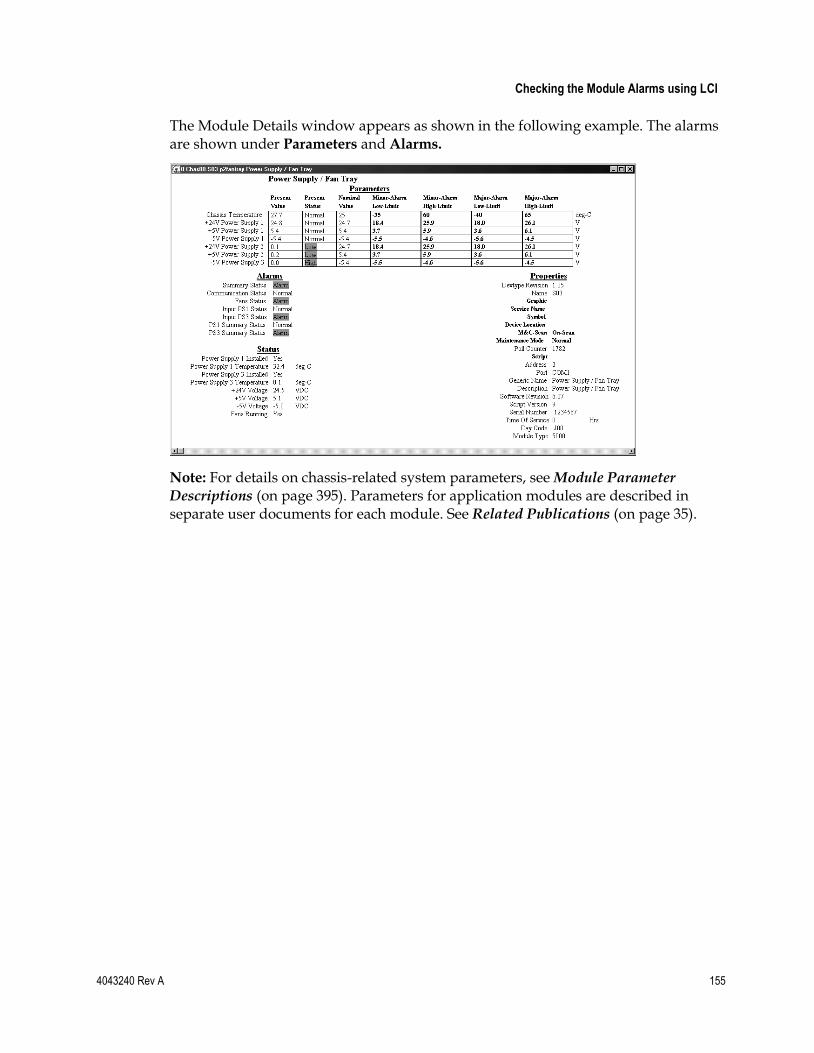
Checking the Module Alarms using LCI
4043240 Rev A 155
The Module Details window appears as shown in the following example. The alarms are shown under Parameters and Alarms.
Note: For details on chassis-related system parameters, see Module Parameter Descriptions (on page 395). Parameters for application modules are described in separate user documents for each module. See Related Publications (on page 35).

Chapter 6 LCI Operation
156 4043240 Rev A
Modifying Module Alarm Limits using LCI
To Modify Alarm Limits using LCI
Using LCI, you can modify alarm limits for parameters that allow for such changes.
1 In the module tree, right-click the module, and then click Details.
The Module Details window appears as shown in the following example. The alarm limits are shown under Parameters.

Modifying Module Alarm Limits using LCI
4043240 Rev A 157
2 Double-click the limit you want to change. This example shows a Change Value dialog box for the Power Supply 1 +24V Minor Low Limit parameter.
3 To change the limit value, type the desired value in the Command to box.
4 Click Execute. The new value appears in the alarm limit column.
Note: For details on chassis-related system parameters, see Module Parameter Descriptions (on page 395). Parameters for application modules are described in separate user documents for each module. See Related Publications (on page 35).

Chapter 6 LCI Operation
158 4043240 Rev A
Checking Manufacturing Data using LCI
To Check Manufacturing Data using LCI
Using LCI, you can check the manufacturing data for a selected module.
1 In the module tree, right-click the module, and then click Details.
The Module Details window appears as shown in the following example. The manufacturing data is displayed under Properties.
2 Proceed with viewing the manufacturing data.
Note: For details on chassis-related system parameters, see Module Parameter Descriptions (on page 395). Parameters for application modules are described in separate user documents for each module. See Related Publications (on page 35).
4043240 Rev A 159
Introduction
This chapter explains the procedures for adding and removing ICIM users and for changing user access and authorization levels.
Note: ICIM software configuration MSO1 supports user management from the ICIM front panel keypad interface. For details, refer to ICIM Operation (on page 101).
7 Chapter 7 User Management
In This Chapter
Introduction ......................................................................................... 160
Replacing the Default Admin Account ............................................ 163
Working With User Accounts ........................................................... 167
User Lockout ....................................................................................... 174

Chapter 7 User Management
160 4043240 Rev A
Introduction The ICIM (ICIM2 or ICIM2-XD) supports up to 16 user accounts. This chapter describes user accounts in detail, and explains how the system administrator (a user with Admin level security access) may set up and edit user accounts through the CLI or Web Interface. Additionally, this chapter includes a table listing access levels and corresponding resources, identifying the activities available to users with specific privileges.
User Accounts
Each user account is set up with a username and password. To initiate an account, the system administrator first chooses the access level and the status. Accounts to be activated immediately are given the status of enable, while those whose activation should be delayed are given the status of disable. The system administrator may also adjust the (single) inactivity timeout as well as the limit of failed log-in attempts for the ICIM.
When a user logs onto the ICIM via the CLI or Web Interface, the username and password are checked for authentication. A check is also performed to ensure that the user account is enabled. Users with disabled accounts are not permitted access to the ICIM.
Additionally, security levels are compared to ensure that the user is authorized to access only the options appropriate to their access level. Another check verifies that the user has not reached the login failure limit as defined by the system administrator and saved in the ICIM. A trap is sent if a user reaches the failed login attempts limit, and the user is prevented from making further log-in attempts for a designated lockout time period.
Usernames
Usernames, also known as login IDs, are formed from the alphanumeric characters A through Z (uppercase), a through z (lowercase), and the numbers 0 through 9. Special characters are not supported in login IDs. Usernames must have at least 6 characters, cannot exceed 14 characters, and must contain at least one alphabetic character and one numeric character. The username cannot be changed once it is created. If entered incorrectly, the system administrator must delete the user account and create a new account using the correct username, password, status, and access level.

Introduction
4043240 Rev A 161
Passwords
Passwords are formed from the alphanumeric characters A through Z (uppercase), a through z (lowercase), the numbers 0 through 9, and may include other printable keyboard characters. Control characters are not supported. Passwords must have at least 6 characters, cannot exceed 14 characters, and must contain at least one alphabetic character and one numeric character. Additionally, the password may not include or consist solely of the username (login ID). For security reasons, passwords are not echoed when adding, changing, or entering them at login. If you forget your password, contact the system administrator, as only he or she is able to change it. Users with Admin level privileges can change the password for any user.
Security Levels
User account security levels define the privileges available to users at that level. Choices are Read-Only, Read-Write, and Admin. The system administrator must have Admin privileges in order to add, change, or delete user accounts, or to modify system settings for the ICIM and the modules in its domain.
Users who do not need to modify module alarm thresholds, controls, or CLLI codes should be assigned Read-Only privileges. Users who need to regulate module information or change CLLI codes need Read-Write privileges.
See Features Available via Remote User Interface (on page 383) for details regarding features available through the remote interface and user access levels required to view or edit data elements.
Account Enable or Disable
Each account is assigned a status of enable or disable. If an account is enabled, it may be used right away. If disabled, the account may not be accessed until the system administrator has activated it. The disabled account status is useful for employees who are temporarily unavailable because they have not started work yet or are on vacation.
Each time someone attempts to log onto a disabled account, a trap is sent alerting management to the event. The attempt is also logged in the event log.
Note: If you discover that your account is disabled, see your system administrator.
Chapter 7 User Management
162 4043240 Rev A
Login Thresholds
The login threshold defines the number of failed login attempts that must occur before a maximum threshold trap is sent. Admin level users may adjust the login threshold for the ICIM. This threshold is the same for all users on a particular ICIM. The default is 5 times, and the range is from 0 to 15. Login failure threshold checking may be disabled by setting the threshold to 0. A failed login attempt trap is sent for every failed login attempt.
User Lockout
Beginning with System Release 2.01, User Lockout may be enabled to prevent users who exceed the maximum failed login attempts threshold from logging in for a designated lockout interval (60 minutes by default). Locked-out users may try to log in again after the user lockout period expires or after an administrator removes the lockout. For further details, see User Lockout (on page 174).
Inactivity Timeout
The inactivity timeout is the number of minutes that a user account must be idle following login before it is automatically logged out by the ICIM. The timeout value is the same number of minutes for all users on a particular ICIM. The default is 10 minutes, but this value may be set anywhere from 1 to 60 minutes by a user with Admin privileges. The inactivity timeout cannot be disabled.

Replacing the Default Admin Account
4043240 Rev A 163
Replacing the Default Admin Account All ICIMs ship from the factory with a single predefined Admin level account. By default, this account has the username Administrat0r and the password AdminPassw0rd.
For security reasons, we strongly recommend that the system administrator add a new Admin user as the first step after starting up the ICIM. After this new Admin user is added, the default Admin user account may be deleted.
Important: Before deleting the default Admin user account, be sure that you have created a new Admin account and noted its login defaults for future reference. Failure to remember the new username and password may result in being locked out of the ICIM permanently. You cannot revert to the default Admin username after you delete them.
To Replace the Default Admin Account
Complete the following steps to replace the default Admin account.
From the CLI
1 Log on to the ICIM using the default username and password.
The sample dialog below shows the addition of a new user account newAdmin1 with password enterpassword1. CLI> icim ICIM> user add newAdmin1 admin enable Please enter the password: enterpassword1 Please reenter the password: enterpassword1
Note: Passwords are not echoed to the terminal as they are entered.
2 Type show user, and then confirm that the new user appears in the resulting list of user names.
3 Log out of the ICIM.
4 Log back onto the ICIM using the new Admin account username and password.
5 At the ICIM prompt, type user delete Administrat0r. The following message appears:
You are about to delete user ‘Administrat0r’ from the authorization table.
6 To confirm, type yes, and then press Enter.
7 Type show user, and then confirm that the user Administrat0r no longer appears in the resulting list of user names.
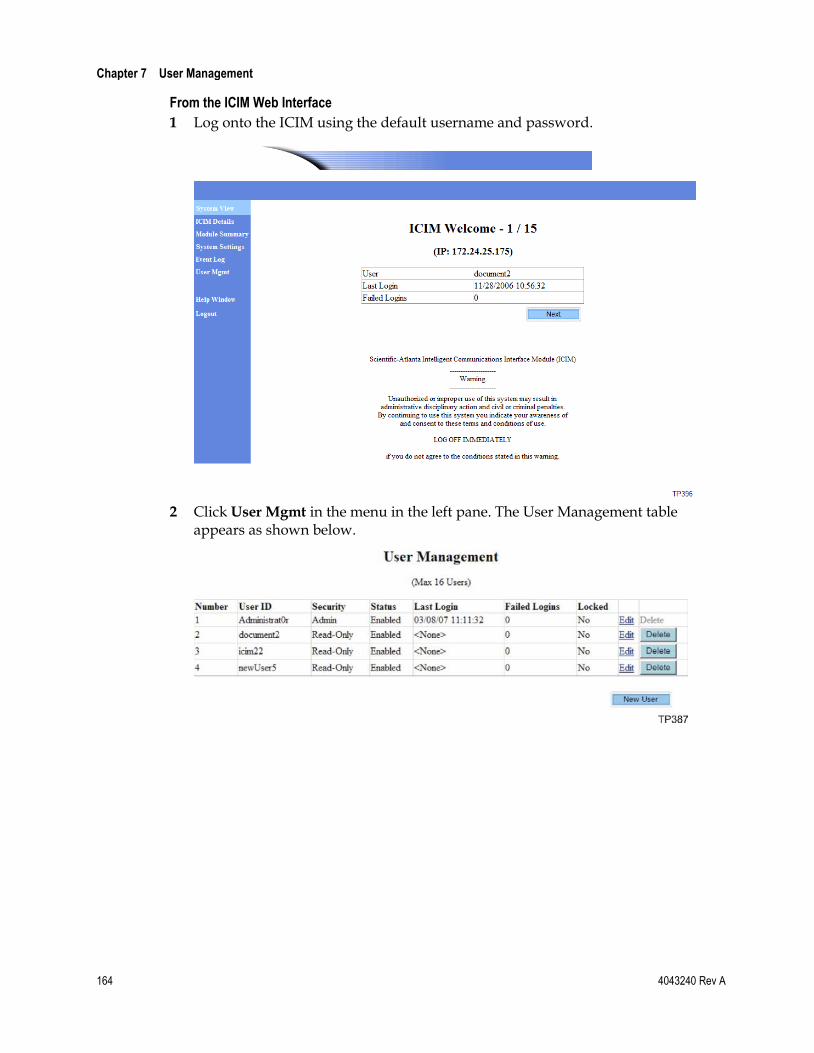
Chapter 7 User Management
164 4043240 Rev A
From the ICIM Web Interface
1 Log onto the ICIM using the default username and password.
2 Click User Mgmt in the menu in the left pane. The User Management table appears as shown below.

Replacing the Default Admin Account
4043240 Rev A 165
3 Click the New User button beneath the User Management table. The New User Information screen appears as shown below.
4 Enter the User ID and Password in the fields provided, and then enter the password again in the Confirm Password field.
Note: The password information you enter is not displayed.
5 Select the appropriate Security Level and Status from the drop-down menus.
6 Click the Save button to save your settings.
7 Log out of the ICIM.
8 Log back onto the ICIM using the new Admin account name and password. For example: newAdmin1 enterpassword1
9 Click User Mgmt in the menu in the left pane.
10 When the User Management Table appears, move the mouse to the delete button next to the row with the default Admin account username Administrat0r.

Chapter 7 User Management
166 4043240 Rev A
11 Click the delete button to remove the default Admin account.
Note:
Keep track of the Administrator username and password. There is no way to retrieve the default username and password after you delete them.
Use the new Administrator account whenever performing system administrator tasks.

Working With User Accounts
4043240 Rev A 167
Working With User Accounts The system administrator may perform any of these functions related to user accounts:
Add new user accounts to give new users access to the ICIM via the CLI and Web Interface.
Change the password, security access level, or status (enabled or disabled) for a user account.
Unlock user accounts that have become locked due to excessive failed login attempts.
Delete user accounts that were entered in error or are no longer needed.
View a list of currently logged in users.
This section describes the steps for each of these procedures.
To Add a New User
When setting up a new account, the system administrator first determines the appropriate user access level for the account. The administrator then determines whether the account will come up in a disabled or enabled state.
Complete the following steps to add a new user.
From the CLI
1 Log on to the ICIM using an account with Admin privileges.
2 Enter ICIM mode.
3 Add the user at the ICIM prompt. For example: ICIM> user add newUser1 read enable Please enter the password: userpassword1 Please reenter the password: userpassword1
Note: Passwords are not echoed to the terminal as they are entered.
4 Type show user, and then confirm that the new user appears in the resulting list of usernames.
ICIM> show user LOGIN IDENTIFIER ACCESS LEVEL STATUS LAST LOGIN FAILED LOCKED sysAdmin ADMIN Enabled 11/21/06 15:02:47 0 No icim22 ADMIN Enabled 11/07/06 10:05:46 0 No newAdmin1 ADMIN Enabled 11/21/06 15:06:11 0 No newUser1 READ Enabled 00/00/00 00:00:00 0 No
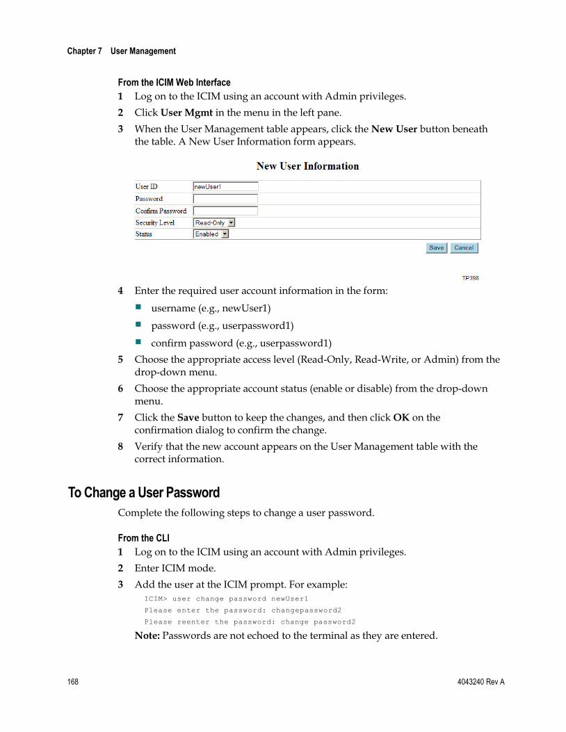
Chapter 7 User Management
168 4043240 Rev A
From the ICIM Web Interface
1 Log on to the ICIM using an account with Admin privileges.
2 Click User Mgmt in the menu in the left pane.
3 When the User Management table appears, click the New User button beneath the table. A New User Information form appears.
4 Enter the required user account information in the form:
username (e.g., newUser1)
password (e.g., userpassword1)
confirm password (e.g., userpassword1)
5 Choose the appropriate access level (Read-Only, Read-Write, or Admin) from the drop-down menu.
6 Choose the appropriate account status (enable or disable) from the drop-down menu.
7 Click the Save button to keep the changes, and then click OK on the confirmation dialog to confirm the change.
8 Verify that the new account appears on the User Management table with the correct information.
To Change a User Password
Complete the following steps to change a user password.
From the CLI
1 Log on to the ICIM using an account with Admin privileges.
2 Enter ICIM mode.
3 Add the user at the ICIM prompt. For example:
ICIM> user change password newUser1 Please enter the password: changepassword2 Please reenter the password: change password2
Note: Passwords are not echoed to the terminal as they are entered.

Working With User Accounts
4043240 Rev A 169
From the ICIM Web Interface
1 Log on to the ICIM using an account with Admin privileges.
2 Click User Mgmt in the menu in the left pane.
3 When the User Management table appears, click the Edit button on the row next to the account with the password to be changed.
4 When the edit window appears, verify that you are changing the correct account.
5 Type the new password in the password box (e.g., changepassword2).
6 Confirm the password in the confirmation box (e.g., changepassword2).
Note: Passwords are not echoed to the terminal as they are entered.
7 Click the Save button near the Confirm Password field.
8 When the OK to Save dialog box appears, choose Save.
9 Confirm that the user appears on the User Management table.
To Change a User Security Level
Complete the following steps to change a user security level.
From the CLI
1 Log on to the ICIM using an account with Admin privileges.
2 Enter ICIM mode.
3 Edit the user information at the ICIM prompt. For example: ICIM> user change access_rights newUser1 readwrite

Chapter 7 User Management
170 4043240 Rev A
4 Type show user, and then confirm that the change appears in the Access Level column of the User Management table.
ICIM> show user LOGIN IDENTIFIER ACCESS LEVEL STATUS LAST LOGIN FAILED LOCKED sysAdmin ADMIN Enabled 11/21/06 15:02:47 0 No icim22 ADMIN Enabled 11/07/06 10:05:46 0 No newAdmin1 ADMIN Enabled 11/21/06 15:06:11 0 No newUser1 READWRITE Enabled 00/00/00 00:00:00 0 No
From the ICIM Web Interface
1 Log on to the ICIM using an account with Admin privileges.
2 Click User Mgmt in the menu in the left pane. The User Management table appears.
3 Click the Edit link on the row next to the account with the Security Level to be changed.
4 In the edit window, verify that you are changing the correct account.
5 Choose the appropriate Security Level from the drop-down menu.
6 Click the Save button on the Security Level row.
7 When the OK to Save dialog box appears, choose Save.
8 Confirm that the User Management table reflects the new security level.

Working With User Accounts
4043240 Rev A 171
To Change User Account Status
Complete the following steps to change (enable or disable) user account status.
From the CLI
1 Log on to the ICIM using an account with Admin privileges.
2 Enter ICIM mode.
3 Edit the user information at the ICIM prompt. For example: ICIM> user change account_status newUser1 disable
4 Type show user, and then confirm that the change appears in the Status column of the User Management table.
ICIM> show user LOGIN IDENTIFIER ACCESS LEVEL STATUS LAST LOGIN FAILED LOCKED sysAdmin ADMIN Enabled 11/21/06 15:02:47 0 No icim22 ADMIN Enabled 11/07/06 10:05:46 0 No newAdmin1 ADMIN Enabled 11/21/06 15:06:11 0 No newUser1 READ Disabled 00/00/00 00:00:00 0 No
From the ICIM Web Interface
1 Log on to the ICIM using an account with Admin privileges.
2 Click User Mgmt in the menu in the left pane. The User Management table appears.
3 Click the Edit link on the row next to the account with the status to be changed.
4 In the edit window, verify that you are changing the correct account.
5 Choose the appropriate Status from the drop-down menu.
6 Click the Save button on the Status row.

Chapter 7 User Management
172 4043240 Rev A
7 When the OK to Save dialog box appears, choose Save.
8 Confirm that the User Management table reflects the new status.
To Unlock User Accounts
Users who reach a specified maximum number of failed ICIM login attempts may have their user accounts locked. These users will be unable to log in until a predetermined lockout interval expires, or until a system administrator unlocks the account. For complete instructions on working with the User Lockout feature and unlocking user accounts, see User Lockout (on page 174).
To Delete a User Account
Complete the following steps to delete a user account.
From the CLI
1 Log on to the ICIM using an account with Admin privileges.
2 Enter ICIM mode.
3 Add the user at the ICIM prompt. For example: ICIM> user delete newUser1
4 Type show user, and then confirm that the account is no longer listed in the resulting User Management table.
ICIM> show user LOGIN IDENTIFIER ACCESS LEVEL STATUS LAST LOGIN FAILED LOCKED sysAdmin ADMIN Enabled 11/21/06 15:02:47 0 No icim22 ADMIN Enabled 11/07/06 10:05:46 0 No newAdmin1 ADMIN Enabled 11/21/06 15:06:11 0 No
From the ICIM Web Interface
1 Log on to the ICIM using an account with Admin privileges.
2 Click User Mgmt in the menu in the left pane. The User Management table appears.
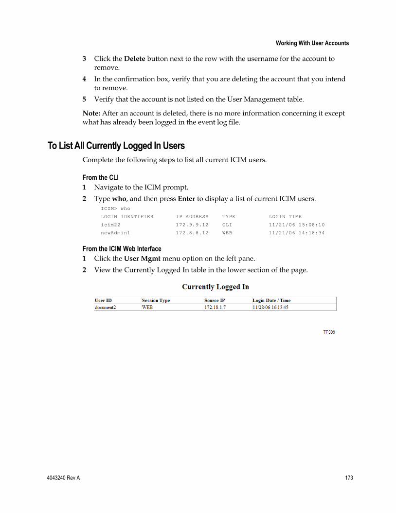
Working With User Accounts
4043240 Rev A 173
3 Click the Delete button next to the row with the username for the account to remove.
4 In the confirmation box, verify that you are deleting the account that you intend to remove.
5 Verify that the account is not listed on the User Management table.
Note: After an account is deleted, there is no more information concerning it except what has already been logged in the event log file.
To List All Currently Logged In Users
Complete the following steps to list all current ICIM users.
From the CLI
1 Navigate to the ICIM prompt.
2 Type who, and then press Enter to display a list of current ICIM users. ICIM> who LOGIN IDENTIFIER IP ADDRESS TYPE LOGIN TIME icim22 172.9.9.12 CLI 11/21/06 15:08:10 newAdmin1 172.8.8.12 WEB 11/21/06 14:18:34
From the ICIM Web Interface
1 Click the User Mgmt menu option on the left pane.
2 View the Currently Logged In table in the lower section of the page.

Chapter 7 User Management
174 4043240 Rev A
User Lockout The User Lockout feature imposes a temporary lockout on ICIM users who reach the maximum number of failed login attempts. Users who are locked out will not be able to log in to the ICIM until the lockout interval expires, even if they try to log in using the correct login information.
By default, User Lockout is enabled with a lockout interval of 60 minutes. Admin users can select any lockout interval from 1 to 60 minutes, or can set the interval to 0 to disable User Lockout. All changes made to the lockout interval are recorded in the event log.
Admin users have commands available for checking the lockout time remaining by user and for unlocking a locked user account before the lockout interval expires. Admin users and users with unknown user names are not subject to lockouts. Lockout data is stored in volatile ICIM memory, so if the ICIM reboots, this data is lost and all users are unlocked.
This section describes the following User Lockout actions available to Admin users:
View the current lockout interval
Specify a new lockout interval
View locked-out users
View lockout time remaining by user
Unlock a locked-out user
Admin users can perform all of these actions through CLI commands, and can view the current lockout interval, specify a new interval, and view locked-out users through the ICIM Web Interface.
To View the Current Lockout Interval
Complete the following steps to view the current status of the User Lockout feature.
From the CLI
1 Log on to the ICIM using an account with Admin privileges.
2 Enter ICIM command mode.
3 Type show lockout, and then press Enter. The system displays the current user lockout interval, as shown in the example below. ICIM> show lockout LOCKOUT 60 SUCCESS! ICIM>

User Lockout
4043240 Rev A 175
The number following LOCKOUT is the current length of the lockout interval in minutes. An interval of 0 means that user lockout is disabled.
Note: You can use info lockout instead of show lockout; the two commands have identical functions.
From the ICIM Web Interface
1 Log on to the ICIM using an account with Admin privileges.
2 Click System Settings in the menu in the left pane. The System Settings table appears, as shown in the example below.
3 Note the value in the Lockout Interval field. This number indicates the current length of the lockout interval in minutes. A value of 0 means that user lockout is disabled.
To Specify a New Lockout Interval
Complete the following steps to either disable User Lockout or to enable this feature and specify a new lockout interval.
From the CLI
1 Log on to the ICIM using an account with Admin privileges.
2 Enter ICIM mode.
3 Type set lockout x, where x is a whole number from 0 to 60, and then press Enter. The system acknowledges your entry, as shown in the example below.
ICIM> set lockout 30 SUCCESS! ICIM>
Note:
Setting the lockout interval to 0 disables user lockout.
Never change the User Lockout interval while a user is locked, as this may result in an unexpected actual lockout interval for the user.

Chapter 7 User Management
176 4043240 Rev A
From the ICIM Web Interface
1 Log on to the ICIM using an account with Admin privileges.
2 Click System Settings in the menu in the left pane.
3 When the System Settings table appears, click in the Lockout Interval field and type the desired lockout value in the space provided.
4 Click Apply to save your changes, or click Cancel to abort.
To View Locked-Out Users
Complete the following steps to view a list of all users and their current lockout status.
From the CLI
1 Log on to the ICIM using an account with Admin privileges.
2 Enter ICIM mode.
3 Type show user, and then press Enter. The system displays a list of all users, as shown in the example below.
ICIM> show user LOGIN IDENTIFIER ACCESS LEVEL STATUS LAST LOGIN FAILED LOCKED Administrat0r ADMIN Enabled 03/08/07 11:11:32 0 No document2 READ Enabled <None> 0 Yes icim22 READ Enabled <None> 0 No newUser5 READ Enabled <None> 0 No
4 Check the values in the LOCKED column. Any users with YES in this column, such as document2 in the example above, are currently locked out.
Note: When a user account becomes locked, the Failed count (number of failed login attempts) is returned to zero.

User Lockout
4043240 Rev A 177
From the ICIM Web Interface
1 Log on to the ICIM using an account with Admin privileges.
2 Click User Mgmt in the menu in the left pane. The User Management table appears as shown in the example below.
3 Note the value in the LOCKED column. Any users with YES in this column, such as firstUser2 in the example above, are currently locked out.
To View Lockout Time Remaining by User
Note: This feature is available only to Admin users and is accessible only through CLI.
Complete the following steps to view the lockout time remaining for all currently locked out users.
From the CLI
1 Log on to the ICIM using an account with Admin privileges.
2 Enter ICIM mode.
3 At the ICIM prompt, type show lockedusers, and then press Enter. A listing of all currently locked out users and their remaining lockout time appears, as shown in the example below.
ICIM> show lockedusers LOCKED USER MINUTES UNTIL UNLOCK firstUser2 12 SUCCESS! ICIM>
Note: If no users are currently locked out, the word (none) will appear in the list.

Chapter 7 User Management
178 4043240 Rev A
To Unlock a Locked-Out User
Note: This feature is available only to Admin users and is accessible only through CLI.
Complete the following steps to unlock a user account that has been locked due to excessive incorrect login attempts.
From the CLI
1 Log on to the ICIM using an account with Admin privileges.
2 Navigate to the ICIM prompt.
3 Type user unlock <username>, where <username> is the name of the user to be unlocked, and then press Enter.
ICIM> user unlock firstUser2 SUCCESS! ICIM>
The user account is now unlocked, and the user will be able to attempt to log in again.
Alternative Methods
There are two other ways to unlock a user account that has been locked out:
Cycle power to the ICIM off and then on again. Because lockout information is stored in volatile ICIM memory, cycling power to the ICIM returns all users to default unlocked status.
In the Web Interface, use the Unlock User feature in the Edit User window under User Management. For details, see To Change User Account Status in Working with User Accounts (on page 167).
Note: Never change the User Lockout interval while a user is locked, as this may result in an unexpected actual lockout interval for the user.
4043240 Rev A 179
The ICIM uses an event log to record certain events in the Prisma II system. This chapter describes the structure of the event log and identifies actions that it may record. This chapter provides instructions for viewing the event log using the CLI or ICIM Web Interface, and for maintaining the event log via CLI commands.
8 Chapter 8 Event Log
In This Chapter
Introduction ......................................................................................... 180
Viewing the Event Log ....................................................................... 184
Clearing the Event Log ...................................................................... 186
Setting Event Log Filter Parameters ................................................. 187
Event Log-Related Traps ................................................................... 189
Downloading and Viewing the Event Log Remotely .................... 191

Chapter 8 Event Log
180 4043240 Rev A
Introduction The ICIM maintains a log of significant events in the Prisma II system due to user activity unrelated to the network management system (NMS). The event log can be viewed by Admin level users through the CLI or ICIM Web Interface. It can also be downloaded to an FTP server for offline viewing.
Certain types of events can be selected for exclusion from the event log. Additionally, changes made through the MIB, usually by the NMS, are not part of the event log.
The event log holds up to 5,000 events. If a new event is logged when the log is already full, the oldest event is removed and the new event is added. To minimize log wrapping, several traps are sent to indicate that the log is nearing capacity, and one trap is sent to indicate that the log is full.
It is up to the NMS user or administrator to empty the event log periodically when it nears capacity. To empty the event log, the NMS typically will first upload the log file from the ICIM to an FTP server, and then clear the log file for new events.
Event Log Fields
Each event in the event log contains the following six fields.
Date and Time (Timestamp)
This field records the date and time that the event was logged.
User Name (User ID)
This field records the name of the user whose actions caused the event. Some events, such as inserting or removing a module, do not contain a user name.
User Access Rights (Security Level)
This field records the access rights of the user whose actions caused the event. Possible values of this field are:
Admin
Read-Only
ReadWrite
Unknown (e.g., if there is no user name)

Introduction
4043240 Rev A 181
Event Category
This field records the category of the event. Possible values of this field are:
Security
Administration
System
Hardware
Provision
Event Action ID
This field records the action ID of the event. Possible values are detailed later.
Event Description
This field contains text describing the event in more detail. For example, if a module is inserted, the description lists the chassis and slot numbers for the insertion.
Event Action IDs
Each event that may appear in the event log is identified by a unique character string called an event action ID. The table below lists the action IDs for these events and identifies their respective event categories.
Note: Action IDs may be displayed differently depending on whether the log is viewed through the CLI or the ICIM Web Interface.
Event Action ID Event Category
LOGIN_SUCCESS SECURITY
LOGIN_FAILED SECURITY
LOG_OFF SECURITY
SESSION_TIMEOUT SECURITY
LOGIN_THRSHLD_RCHD SECURITY
IPSEC_ENABLED SECURITY
IPSEC_DISABLED SECURITY
IKE_PEER_ADD SECURITY
IKE_PEER_REMOVE SECURITY
USER_ACCT_LOCKOUT SECURITY
CHG_LOGIN_THRESHOLD ADMINISTRATION

Chapter 8 Event Log
182 4043240 Rev A
Event Action ID Event Category
CHG_TRAP_DESTINATION ADMINISTRATION
CHG_INACTIVITY_TIMER ADMINISTRATION
CHG_USER ADMINISTRATION
GET_USER ADMINISTRATION
CHG_LOG_OPTION ADMINISTRATION
SET_CLOCK ADMINISTRATION
CHG_SNTP ADMINISTRATION
CHG_LOCKOUT_INTERVAL ADMINISTRATION
LOG_NEAR_FULL SYSTEM
LOG_FULL SYSTEM
DOWNLOAD_START SYSTEM
DOWNLOAD_COMPLETE SYSTEM
REBOOT SYSTEM
SYSTEM_ERROR SYSTEM
WATCHDOG_CPU_OVERLOAD SYSTEM
WATCHDOG_REBOOT SYSTEM
EVENTLOG_FORMAT SYSTEM
SELFTEST_FAILED SYSTEM
SNTP_FAILED SYSTEM
MODULE_INSERT HARDWARE
MODULE_REMOVE HARDWARE
CHG_SERVICE_MODE PROVISION
SET_CLLI PROVISION
SET_COMMREAD PROVISION
SET_COMMWRITE PROVISION
SET_COMMTRAP PROVISION
SET_GATEWAY PROVISION
SET_IP PROVISION
SET_SUBNET PROVISION
SET_UPDATEID PROVISION
SET_MODULE_CTRL PROVISION
SET_ALARM_PARAM PROVISION

Introduction
4043240 Rev A 183
Event Action ID Event Category
ADD_ROUTE PROVISION
DELETE_ROUTE PROVISION

Chapter 8 Event Log
184 4043240 Rev A
Viewing the Event Log The event log may be viewed in either of two ways: through the CLI or via the ICIM Web Interface. This section describes both methods.
To View the Event Log through the CLI
Two CLI commands are available for viewing the event log.
The icim show eventlog command displays an abbreviated version of the event log. Only the Date and Time, User Name, and Description fields are included, so most log entries will fit on a single line on the terminal screen.
The icim show eventlogall command displays all log fields: Date and Time, User Name, User Access Rights, Event Category, Action ID, and Description. Some fields use abbreviations to maintain a display that is readable on a terminal.
Examples of each command are shown below.
Abbreviated Event Log
To view an abbreviated version of the event log, use the icim show eventlog command as shown in the following example.
CLI> icim show eventlog
11/17/06 09:24:17 Administrat0r Set ICIM CLLI to ICIM2_CLLI 11/17/06 09:23:33 Administrat0r Log Off 11/17/06 09:22:57 Module inserted (1/12) 11/17/06 09:22:55 Module inserted (1/9) 11/17/06 09:22:32 Administrat0r Login successful 5 log messages displayed
SUCCESS! CLI>
Note: The example above also illustrates that no user name is shown for module insertion events.
Full Event Log
To view a full version of the event log that includes all fields, use the icim show eventlogall command as shown in the following example.
CLI> icim show eventlogall
11/17/06 09:24:17 Administrat0r AD PR SET_CLLI Set ICIM CLLI t o ICIM2_CLLI 11/17/06 09:23:33 Administrat0r AD SE LOG_OFF Log Off 11/17/06 09:22:57 HW MODULE_INSERT Module inserted (1/12) 11/17/06 09:22:55 HW MODULE_INSERT Module inserted (1/9) 11/17/06 09:22:32 Administrat0r AD SE LOGIN_SUCCESS Login successfu l 5 log messages displayed
SUCCESS! CLI>

Viewing the Event Log
4043240 Rev A 185
As shown in the example above, the full view of the event log provides more detail, but may be more difficult to read because the log entries typically do not fit on a single line.
To shorten the entries and help improve readability, abbreviated values are used in the User Access Rights and Event Category columns. The User Access Rights column will contain one of the following abbreviated values:
AD (Admin)
RW (ReadWrite)
RO (Read-Only)
Note: If the user name is blank (as in the Module Insert event), the User Access Rights field will also be blank.
Similarly, the Event Category column will contain one of the following values:
SE (Security)
AD (Administration)
SY (System)
HW (Hardware)
PR (Provisioning)
To View the Event Log through the Web Interface
After logging in, select Event Log from the menu in the left column. The Event Log table appears resembling the example below.
The log will be displayed one page at a time, with up to 25 logs per page. Use the Previous and Next links to scroll through any additional pages.

Chapter 8 Event Log
186 4043240 Rev A
Clearing the Event Log To prevent wrapping when the event log gets full, you must clear the event log periodically. Typically, you do this by first downloading the event log to an FTP server, and then clearing the event log from ICIM memory.
The event log may be cleared through the CLI or the ICIM Web Interface. This section describes both methods.
To Clear the Event Log through the CLI
To clear the event log, use the icim eventlogclear command. This command clears the entire event log. You will be prompted for confirmation before the log is cleared, as shown in the example below.
CLI> icim eventlogclear
You are about to remove 6 entries from the system log. Are you sure you want to proceed (Yes/No)? yes
SUCCESS! CLI>
To Clear the Event Log through the Web Interface
To clear the event log through the ICIM Web Interface, first display the event log in the Web window, and then click the Clear Event Log button. You will be asked to confirm the operation.
Click OK to continue.

Setting Event Log Filter Parameters
4043240 Rev A 187
Setting Event Log Filter Parameters Associated with the event log are filter parameters that determine whether certain types of events are included in or excluded from logging.
Events are included or excluded from logging according to event category. Each event belongs to one of the following event categories:
Administration
Hardware
Provisioning
Security
System
Administration and Security events are always included in the event log. System, Hardware, and Provisioning events may be included or excluded by changing filter parameters. Changes to event log filter parameters only affect the logging of future events. Events that are already part of the log file will remain in the log file, regardless of subsequent filter parameter changes.
You can view and set event log filter parameters through the CLI or the ICIM Web Interface. This section describes both methods.
To View Filter Parameters through the CLI
To view the current filter parameter settings, use the icim show eventlogfilter command, as shown in the following example.
CLI> icim show eventlogfilter
Event Log Settings:
Provisioning Events: on Hardware Events: on System Events: on
(a value of "on" means to log events of that category)
SUCCESS! CLI>
To Set Filter Parameters through the CLI
To change filter parameters through the CLI, use the following command:
icim eventlogfilter <category> <setting>
The possible values for <category> and <setting> are listed below along with their resulting effects on the filter settings.

Chapter 8 Event Log
188 4043240 Rev A
<category> <setting> Result
hardware on Includes hardware events in the event log.
hardware off Excludes hardware events from the event log.
provisioning on Includes provisioning events in the event log.
provisioning off Excludes provisioning events from the event log.
system on Includes system events in the event log.
system off Excludes system events from the event log.
The example below turns off logging of hardware events, and then shows the filter parameters settings.
CLI> icim eventlogfilter hardware off
SUCCESS! CLI> icim show eventlogfilter
Event Log Settings:
Provisioning Events: on Hardware Events: off System Events: on
(a value of "on" means to log events of that category)
SUCCESS! CLI>
To View Filter Parameters through the Web Interface
To view the current filter parameter settings, log in to the Web Interface and then select the System Settings page from the left menu. The second group of items on this page shows the event log settings.
To Set Filter Parameters through the Web Interface
To change the current filter parameter settings, use the check boxes in the Event Log Settings group on the System Settings page.
Check the box beside each event category to be included in the log, and clear the box beside each category to be excluded. When finished, click the Apply button to save your changes, or click Cancel to abort.

Event Log-Related Traps
4043240 Rev A 189
Event Log-Related Traps To alert the NMS of possible lost event log entries due to wrapping, the ICIM sends several traps as the event log nears capacity. A trap is sent when the log is 80%, 85%, 90%, 95%, and 100% full. This means that five traps total are sent if the NMS takes no action to clear the log. Once the log reaches 100% full and begins wrapping, no more log-full traps are sent.
The traps are of the Enhanced (TelcoAlarm) variety, and contain all the varbinds defined as part of that trap type. All traps except the 100% full trap specify LogMemHalfFull as the p2TrapLogLabel varbind, although the p2TrapLogDescr varbind specifies the percentage. The 100% full trap specifies LogMemoryFull as the p2TrapLogLabel varbind.
Examples of the 80% full trap and the 100% full trap are provided below.
Example: 80% Full Trap Specific: 9 Message reception date: 9/13/2006 Message reception time: 2:27:25.066 PM Time stamp: 0 days 00h:11m:20s.13th Message type: Trap (v1) Protocol version: SNMPv1 Transport: IP/UDP Agent Address: 172.24.28.193 Port: 1035 Manager Address: 172.18.9.66 Port: 162 Community: prismatrap SNMPv1 agent address: 172.24.28.193 Enterprise: p2trapEvents Bindings (15) Binding #1: p2TrapLogSequence *** (int32) 12 Binding #2: p2TrapLogSeverity *** (int32) warning(3) Binding #3: p2TrapLogState *** (int32) event(3) Binding #4: p2TrapLogLabel *** (octets) LogMemHalfFull Binding #5: p2icimStatusMsg.0 *** (int32) 0 Binding #6: p2TrapLogText *** (octets) ICIM2 Binding #7: p2chassisID.2.15 *** (int32) 2 Binding #8: p2slotID.2.15 *** (int32) 15 Binding #9: p2moduleCLLIcode.2.15 *** (octets) 1.2.243 Binding #10: p2moduleCLEIcode.2.15 *** (octets) (zero-length) Binding #11: p2TrapLogTime *** (octets) 2006-9-13,1:51:39.42 Binding #12: p2TrapLogDateTime *** (octets) Wed, 13 Sep 2006 01:51:39 EST Binding #13: p2TrapLogValue *** (octets) N/A Binding #14: p2TrapLogUnit *** (octets) N/A Binding #15: p2TrapLogDescr *** (octets) Log memory is %80 full

Chapter 8 Event Log
190 4043240 Rev A
Example: 100% Full Trap Specific: 9 Message reception date: 9/13/2006 Message reception time: 2:44:27.081 PM Time stamp: 0 days 00h:28m:22s.13th Message type: Trap (v1) Protocol version: SNMPv1 Transport: IP/UDP Agent Address: 172.24.28.193 Port: 1039 Manager Address: 172.18.9.66 Port: 162 Community: prismatrap SNMPv1 agent address: 172.24.28.193 Enterprise: p2trapEvents Bindings (15) Binding #1: p2TrapLogSequence *** (int32) 16 Binding #2: p2TrapLogSeverity *** (int32) warning(3) Binding #3: p2TrapLogState *** (int32) event(3) Binding #4: p2TrapLogLabel *** (octets) LogMemoryFull Binding #5: p2icimStatusMsg.0 *** (int32) 0 Binding #6: p2TrapLogText *** (octets) ICIM2 Binding #7: p2chassisID.2.15 *** (int32) 2 Binding #8: p2slotID.2.15 *** (int32) 15 Binding #9: p2moduleCLLIcode.2.15 *** (octets) 1.2.243 Binding #10: p2moduleCLEIcode.2.15 *** (octets) (zero-length) Binding #11: p2TrapLogTime *** (octets) 2006-9-13,2:8:41.45 Binding #12: p2TrapLogDateTime *** (octets) Wed, 13 Sep 2006 02:08:41 EST Binding #13: p2TrapLogValue *** (octets) N/A Binding #14: p2TrapLogUnit *** (octets) N/A Binding #15: p2TrapLogDescr *** (octets) Log memory is %100 full

Downloading and Viewing the Event Log Remotely
4043240 Rev A 191
Downloading and Viewing the Event Log Remotely You can download the event log from the ICIM to an FTP server at any time. We recommend downloading the file before it reaches capacity to avoid losing the oldest events in the log as new events are added.
Transfer of the event log file is initiated using SNMP via the prismaIIFileMgmtGroup MIB. For additional information, see Event Log File Management (on page 209).
To Download the Event Log File
Complete the following steps in SNMP to initiate the event log file download.
1 Set p2icimFileMgmtUsername to the FTP user name.
2 Set p2icimFileMgmtPassword to the FTP password.
3 Set p2icimFileMgmtIpAdress to the IP address of the FTP server.
4 Set p2icimFileMgmtFilePath to the path of the destination file on the FTP server.
5 Set p2icimFileMgmtFileName to the destination file name on the FTP server.
6 Set p2icimFileMgmtCmd to upload(1).
7 Set p2icimFileMgmtAction to execute(2).
In response to these commands, the ICIM will log into the FTP server and transfer the event log file.
The event log file is a text file with space-separated columns, formatted in a manner almost identical to the response to the icim show eventlogall command from the CLI. Most recent events appear at the bottom of the file, and there is no file header.

Chapter 8 Event Log
192 4043240 Rev A
A sample portion of the event log file as downloaded from the ICIM to an FTP server is shown below.
In this example:
The date-time format is yyyy/mm/dd hh:mm:ss, and seconds are shown without leading zeros.
Event categories are abbreviated, with Security shown as SE and Provisioning shown as P.

4043240 Rev A 193
Introduction
This chapter provides information about using Simple Network Management Protocol (SNMP) commands for remote system monitoring and control. The ICIM recognizes SNMP v1 and v2c commands, but only sends SNMP v1 traps to ensure backward compatibility.
For details on chassis-related system parameters, see Module Parameter Descriptions (on page 395). Parameters for application modules are described in separate user documents for each module. See Related Publications (on page 35).
9 Chapter 9 SNMP Management
In This Chapter
Introduction ......................................................................................... 194
ICIM MIB ............................................................................................. 195
Module MIB ......................................................................................... 226
Remote Reboot of ICIM and Modules ............................................. 253
Prisma II Traps .................................................................................... 254
Alarm Threshold Modification ......................................................... 293
System Behavior .................................................................................. 295
Frequently Asked Questions ............................................................. 296

Chapter 9 SNMP Management
194 4043240 Rev A
Introduction Simple network management protocol (SNMP) is an ISO standard communication protocol often used by network and element management systems to monitor network devices for alarms and other significant conditions.
SNMP accesses information about network devices through management information base (MIB) objects. MIBs are hierarchical tree-structured descriptions used to define database elements. SNMP is used to manage individual data elements and the values assigned to MIB objects.
SNMP addresses a single MIB object using a numeric string called an object identifier (OID). The OID defines a branching path through the hierarchy to the location of the object. In addition to the OID, a MIB object is known by its object descriptor, a text string intended to be more meaningful to a human operator. The OID and object descriptor are unique to each MIB object.
Also defined for each MIB object is the access that SNMP can afford to the object data value. For example, if a MIB object has read-write access, SNMP can be used to both get (retrieve) and set (define or change) the value of the object. If an object is read-only, SNMP can be used to get the object value, but not to change it.
Prisma II Enterprise MIBs
The Prisma II Enterprise MIBs allow easy access to ICIM, trap, and module information via SNMP. There are two proprietary MIBs for management and event notification:
SCIATL-PRISMAII-ICIM-MIB contains a scalar list of values used to control Prisma II ICIM management functions. Included are two trap tables, one for trap configuration and the other for trap logging.
Current version: 200702222200Z
SCIATL-PRISMAII-MODULE-MIB contains a series of tables for managing Prisma II application modules.
Current version: 200702062209Z
These MIBs are based on the original ICIM MIBs, PRISMAII-ICIMR13-MIB and PRISMAII-MODULER13-MIB, which are now considered obsolete.
Details of the elements of the ICIM MIB and MODULE MIB are provided in the sections below.

ICIM MIB
4043240 Rev A 195
ICIM MIB MIB objects for the ICIM fall into several categories. Information includes the state of the ICIM in reference to network settings, FTP, download control, and manufacturing data. Each of the ICIM object identifiers appears below with a description and other pertinent information concerning the element.
To View the ICIM MIB
To view the Prisma II ICIM MIB, be sure to compile and load both proprietary MIBs, SCIATL-PRISMAII-ICIM-MIB and SCIATL-PRISMAII-MODULE-MIB, in your MIB browser.
The ICIM object identifier (OID) is 1.3.6.1.4.1.1429.1.6.2.2.13.100. This is the dot version of the full path that expands to:
iso(1).org(3).dod(6).internet(1).private(4).enterprises(1).scientificatlanta(1429).saTerr(1).saTerrOptical(6).saTerrOpticalPrismaII(2).saPrismaIIrev2(2).saPrismaIIicim(13).prismaIIicim(100).
ICIM MIB Elements
The ICIM MIB contains the following elements, which are discussed in detail in this section.
ICIM MIB Element Example Value
p2icimChassisID 6
p2icimSlotID 15
p2icimSMCAddress 615
p2icimType 5011
p2icimManufactureData ICIM2
p2icimSerialNumber AADORSF
p2icimHardwareRevision BdRev87A
p2icimSoftwareRevision 2.00.08
p2icimSoftwareDate 11032006
p2icimTimeOfService 219
p2icimMACAddr 00:14:FF:FF:FF:61
p2icimIPAddr 172.24.24.24
p2icimSubnetMask 255.255.255.0

Chapter 9 SNMP Management
196 4043240 Rev A
ICIM MIB Element Example Value
p2icimGatewayAddr 172.24.24.254
p2PreviousIP 174.24.24.23
p2icimUpdateChassisIDs 0
p2icimAttnStatus High (1)
p2icimDomainSize 6
p2icimNextImage currentActive (1)
p2icimActiveCodeRevision 2.00.08
p2icimInactiveCodeRevision N/A
p2icimBootCodeRevision 2.00.03
p2icimFtpServerAddr 172.24.13.12
p2icimFtpUsername Set
p2icimFtpPassword Set
p2icimDownLdDir (zero-length)
p2icimDownLdFilename ICIM2_2_00_08_app.BIN
p2icimDownLdCmd Cancel (4)
p2icimDownLdState Idle (1)
p2icimDownLdTarget 100
p2icimDownLdResult No-result-available (9999)
p2icimDownLdSignature 1146728270
p2icimDownLdSemaphore 1146720732
p2icimDownLdUser 0
p2icimCLLIcode SCIATL01
p2icimCLEIcode VLLUAA4DAA
p2icimSelfTest ICIM2 Self-Test Passed
p2icimStatusMsg 6 Nov 03 2006 05:50:03 AM Broadcast reboot command successful
p2icimDownLdProg 0
p2icimClock 2006-12-15 11:38:57
p2icimTimeZone EDT
p2icimDateTime Fri, 15 Dec 2006 11:32:57 EST
p2icimNotify 0
p2icimStatusMsgClearKey 2

ICIM MIB
4043240 Rev A 197
p2icimChassisID
The number that appears in the chassis ID switch on the front panel of the chassis in which the ICIM is installed indicates the value for the chassis ID. Valid chassis ID values are 00 to 99 inclusive. However, the use of 00 as the chassis ID value is not recommended in some circumstances, as the following caution explains.
CAUTION:
Setting the chassis ID to 00 is not recommended as it causes the entity MIB to violate RFC-2737 by creating an invalid object identifier. This may affect operation with some management systems that use the entity MIB. In particular, attempts to access the fans (in virtual slot 0) in chassis 00 will fail if made via serial TNCS (or ROSA-EM) or LCI.
Access: read-only
OID: 1.3.6.1.4.1.1429.1.6.2.2.13.100.1
p2icimSlotID
The value in this object identifies the slot number in which the ICIM is installed, and is always 15.
Access: read-only
OID: 1.3.6.1.4.1.1429.1.6.2.2.13.100.2
p2icimSMCAddress
The value in this object is the chassis number times 100 plus the ICIM slot number. Leading zeros may be cropped. Thus, for chassis 20, the p2icimSMCAddress will be 2015.
Access: read-only
OID: 1.3.6.1.4.1.1429.1.6.2.2.13.100.3
p2icimType
The value in this object is used to uniquely identify the ICIM model. In other contexts, this may be referred to as the devtype.
Access: read-only
OID: 1.3.6.1.4.1.1429.1.6.2.2.13.100.4
p2icimManufactureData
This object holds a string of up to 30 characters that describes the ICIM in words. For the ICIM2, the string is ICIM2.
Access: read-only
OID: 1.3.6.1.4.1.1429.1.6.2.2.13.100.5

Chapter 9 SNMP Management
198 4043240 Rev A
p2icimSerialNumber
This object holds the serial number assigned to this unit during the manufacturing process.
Access: read-only
OID: 1.3.6.1.4.1.1429.1.6.2.2.13.100.6
p2icimHardwareRevision
The value in this object is the hardware revision of this ICIM, e.g., BdRev87A.
Access: read-only
OID: 1.3.6.1.4.1.1429.1.6.2.2.13.100.7
p2icimSoftwareRevision
This object is no longer used, but kept in place for backward compatibility. Active, inactive, and boot code revisions display through p2icimActiveCodeRevision, p2icimInactiveCodeRevision, and p2icimBootCodeRevision (described below).
Access: read-only
OID: 1.3.6.1.4.1.1429.1.6.2.2.13.100.8
p2icimSoftwareDate
The value in this object represents the date that the firmware was built, e.g., 01202007 (Jan. 20, 2007).
Access: read-only
OID: 1.3.6.1.4.1.1429.1.6.2.2.13.100.9
p2icimTimeOfService
This object shows the number of hours that this ICIM has been in service, which may be any number of hours starting from 0.
Access: read-only
OID: 1.3.6.1.4.1.1429.1.6.2.2.13.100.10
p2icimMACAddr
This object holds the physical MAC address assigned to this ICIM, in the form 00:11:22:33:44:55.
Access: read-only
OID: 1.3.6.1.4.1.1429.1.6.2.2.13.100.12

ICIM MIB
4043240 Rev A 199
p2icimIPAddr
This object holds the network IP address assigned to this ICIM.
Access: read-only
OID: 1.3.6.1.4.1.1429.1.6.2.2.13.100.13
p2icimSubnetMask
This object holds the network subnet mask used to reach this ICIM.
Access: read-only
OID: 1.3.6.1.4.1.1429.1.6.2.2.13.100.14
p2icimGatewayAddr
This object represents the network gateway address used by this ICIM.
Access: read-only
OID: 1.3.6.1.4.1.1429.1.6.2.2.13.100.15
p2PreviousIP
This object returns the value 0.0.0.0 until the IP address of the ICIM is changed for the first time. After that, it holds the previous IP address.
Access: read-only
OID: 1.3.6.1.4.1.1429.1.6.2.2.13.100.16
p2icimUpdateChassisIDs
Setting the value of this object to 1 updates every module in this ICIM domain with its chassis ID and slot number. As a result, each module sends all of its information to the ICIM. It takes time for the ICIM to update the database with the new data. A get on this object always returns the value 0.
Access: read-write
OID: 1.3.6.1.4.1.1429.1.6.2.2.13.100.19
p2icimAttnStatus
This object will normally display high (1) unless one of the modules pulls the attention line low (2). In that case, the ICIM will service the request from the module, and when complete, will return the attention line to high (1).
Access: read-only
OID: 1.3.6.1.4.1.1429.1.6.2.2.13.100.20
Chapter 9 SNMP Management
200 4043240 Rev A
p2icimDomainSize
This object shows the number of modules managed by this ICIM.
Access: read-only
OID: 1.3.6.1.4.1.1429.1.6.2.2.13.100.21
p2icimNextImage
The value in this object indicates which image will be active following the next ICIM reboot. Values may be current active image (1) or current inactive image (2).
Access: read-only
OID: 1.3.6.1.4.1.1429.1.6.2.2.13.100.22
p2icimActiveCodeRevision
This object displays the active firmware image revision for the ICIM.
Access: read-only
OID: 1.3.6.1.4.1.1429.1.6.2.2.13.100.23
This object is used to determine the active software version. The ICIM can store two flash images, one in the Active area and the other in the Inactive area. The SOUP program is used to download code to the two flash areas and switch between them.
p2icimInactiveCodeRevision
This object displays the inactive firmware image revision for the ICIM.
Access: read-only
OID: 1.3.6.1.4.1.1429.1.6.2.2.13.100.24
This object is used to determine the inactive software version. The ICIM can store two flash images, one in the Active area and the other in the Inactive area. The SOUP program is used to download code to the two flash areas and switch between them.
p2icimBootCodeRevision
This object displays the current boot image revision for the ICIM.
Access: read-only
OID: 1.3.6.1.4.1.1429.1.6.2.2.13.100.25
p2icimFtpServerAddr
WARNING:
This object is for use by the SOUP firmware download utility only. It is not intended for use by system operators.

ICIM MIB
4043240 Rev A 201
Use this object to set the remote FTP server IP address for the download in the form 172.18.1.11. When the ICIM receives a request to start the file transfer process via p2icimDownLdCmd, this string will be accessed for the remote IP address.
Note: If the ICIM has IPsec enabled, the remote PC or workstation must be set up for IPsec and included in the ICIM list of IPsec peers. For detailed instructions, see Setting Up IPsec (on page 315).
Access: read-write
OID: 1.3.6.1.4.1.1429.1.6.2.2.13.100.26
p2icimFtpUsername
WARNING:
This object is for use by the SOUP firmware download utility only. It is not intended for use by system operators.
Use this object to set the remote username for the FTP server. If the object does not contain a value, a get will display “Not set.” For security reasons, if the username is entered and a get operation is requested, “Set” will display rather than the actual entry.
The p2icimFtpUsername may contain up to 31 characters. When the ICIM receives a request to start the file transfer process via p2icimDownLdCmd, this string will be accessed for the remote username.
Access: read-write
OID: 1.3.6.1.4.1.1429.1.6.2.2.13.100.27
p2icimFtpPassword
WARNING:
This object is for use by the SOUP firmware download utility only. It is not intended for use by system operators.
Use this object to set the remote password for the FTP server. If the object does not contain a value, a get operation will display “Not set.” For security reasons, if the password is entered and a get operation is requested, “Set” will display rather than the actual entry.
The p2icimFtpPassword may contain up to 31 characters. When the ICIM receives a request to start the file transfer process via p2icimDownLdCmd, this string will be accessed for the remote password when the ICIM logs into the FTP server.
Access: read-write
OID: 1.3.6.1.4.1.1429.1.6.2.2.13.100.28

Chapter 9 SNMP Management
202 4043240 Rev A
p2icimDownLdDir
WARNING:
This object is for use by the SOUP firmware download utility only. It is not intended for use by system operators.
Use this object to set the remote directory path (excluding filename) on the FTP server where the download file exists. The p2icimDownLdDir may contain up to 127 printable characters. When the ICIM receives a request to start the file transfer process via p2icimDownLdCmd, this string will be accessed for the remote path (without the filename).
Access: read-write
OID: 1.3.6.1.4.1.1429.1.6.2.2.13.100.29
p2icimDownLdFilename
WARNING:
This object is for use by the SOUP firmware download utility only. It is not intended for use by system operators.
Use this object to set the remote filename of the release file on the FTP server where the download file exists. The p2icimDownLdFilename may contain up to 31 printable characters. When the ICIM receives a request to start the file transfer process via p2icimDownLdCmd, this string will be accessed for the remote filename.
Access: read-write
OID: 1.3.6.1.4.1.1429.1.6.2.2.13.100.30
p2icimDownLdCmd
WARNING:
This object is for use by the SOUP firmware download utility only. It is not intended for use by system operators.
This object is used to set commands for execution by the SOUP download utility.
The table below lists all valid commands.
Command Function
ftp-begin (1) Ftps the file using the parameters outlined above (p2icimFtpServerAddr, p2icimFtpUsername, p2icimFtpPassword, p2icimDownLdDir, p2icimDownLdFilename) to the target indicated in p2icimDownLdTarget.
download-boot-begin (2) Downloads the boot image from RAM to flash or from RAM to a module.
download-appl-begin (3) Downloads an application image from RAM to flash or from RAM to a module.

ICIM MIB
4043240 Rev A 203
Command Function
cancel (4) Ends the current operation. This is the initialized state of this OID.
download-exit (5) Exits the download.
version-switch (6) Changes the pointer for the current inactive image to become the current active image following the next reboot.
soft-reboot (7) Initiates a firmware reboot.
hard-reboot (8) Initiates a hardware reboot.
enable-reboot (9) Allows the next reboot command to take effect on the ICIM or module indicated in the p2icimDownLdTarget.
disable-reboot (10) Disallows the next reboot command to take effect on the ICIM or module indicated in the p2icimDownLdTarget.
download-cancel (11) Cancels the download.
inactive (12) Used by the ICIM firmware exclusively during the download.
invalidate-image (13) Instructs the ICIM to erase its inactive image, which is done to prevent use of an application image that may be incompatible with the boot image.
Access: read-write
OID: 1.3.6.1.4.1.1429.1.6.2.2.13.100.31
p2icimDownLdState
This object displays the state machine value to indicate FTP download progress. The values for the download state are set by the download software, and may be one of the following:
Value Meaning
idle (1) Indicates the idle state, which is also the initialized state.
ftp-in-progress (2) Indicates that an image is being transferred to the ICIM.
download-in-progress (3) Indicates that an image is being written to flash or transferred to a module.
version-switch-in-progress (4)
Indicates that the NextImage pointer is being toggled in the ICIM or a module from currentActive to currentInactive, or vice versa.
reboot-in-progress (5) Indicates that an entity (ICIM or module) is being rebooted.
reboot-enable-in-progress (6)
Indicates that an entity is being flagged for reboot.

Chapter 9 SNMP Management
204 4043240 Rev A
Note: If the file being transferred is small, these states may change too quickly to be seen individually.
Access: read-only
OID: 1.3.6.1.4.1.1429.1.6.2.2.13.100.32
p2icimDownLdTarget
WARNING:
This object is for use by the SOUP firmware download utility only. It is not intended for use by system operators.
This object identifies the ICIM or module chassis and slot to upgrade with the release image, in the form of 0015 for chassis 00, slot 15. This may be the broadcast address of 9999. The target must be set before a file may be downloaded.
Access: read-write
OID: 1.3.6.1.4.1.1429.1.6.2.2.13.100.33
p2icimDownLdResult
Perform a get on this object to display the result of the download as one of 47 result codes. The result codes are self-explanatory, e.g., ftp-success(200). P2icimDownLdResult is only valid when the download state is idle.
Access: read-only
OID: 1.3.6.1.4.1.1429.1.6.2.2.13.100.34
p2icimDownLdSignature
This object is used by the element management system when launching the SOUP utility for the download. Performing a get on this object returns a value generated by the ICIM clock. The value of the signature is not necessarily positive. See Remote Firmware Download Feature (on page 299) for details.
Access: read-only
OID: 1.3.6.1.4.1.1429.1.6.2.2.13.100.35
p2icimDownLdSemaphore
WARNING:
This object is for use by the SOUP firmware download utility only. It is not intended for use by system operators.
This object is used together with p2icimDownLdUser exclusively by the SOUP utility to prevent multiple sessions of the SOUP from accessing the ICIM simultaneously. Performing a get on this object returns either 0 or a value generated by the ICIM clock. The value of the semaphore is not necessarily positive. See Remote Firmware Download Feature (on page 299) for details.

ICIM MIB
4043240 Rev A 205
Access: read-write
OID: 1.3.6.1.4.1.1429.1.6.2.2.13.100.36
p2icimDownLdUser
WARNING:
This object is for use by the SOUP firmware download utility only. It is not intended for use by system operators.
This object is used together with p2icimDownLdSemaphore exclusively by the SOUP utility to prevent multiple sessions of the SOUP from accessing the ICIM simultaneously. Performing a get on this object when it is not in use returns the value 0. See Remote Firmware Download Feature (on page 299) for details.
Access: read-write
OID: 1.3.6.1.4.1.1429.1.6.2.2.13.100.37
p2icimCLLIcode
Use this object to set the Common Language Locator ID (CLLI) code for the ICIM. The maximum length of this string is 20 alphanumeric characters.
Access: read-write
OID: 1.3.6.1.4.1.1429.1.6.2.2.13.100.38
p2icimCLEIcode
Use this object to view the Common Language Equipment ID (CLEI) code that is written to the ICIM as part of the manufacturing process. The maximum length of this string is 20 alphanumeric characters. An example of a CLEI code is VLL4AALDAA.
Access: read-only
OID: 1.3.6.1.4.1.1429.1.6.2.2.13.100.39
p2icimSelfTest
Use this object to display the results of the basic functional self-test that the ICIM performs at boot-up. If the ICIM passes the self-test, performing a get on this object returns the message “ICIM Self-Test Passed.” If the ICIM encounters one or more problems, a get on this object returns the message "ICIM Self-Test failed - Error Code” followed by a decimal representation of the hexadecimal code of the failure(s).

Chapter 9 SNMP Management
206 4043240 Rev A
ICIM Test Failed Hexadecimal Code
Decimal Value
SDRAM 0x01000001 16777217
Boot Flash 0x01000002 16777218
Application Flash 0x01000004 16777220
EEPROM 0x01000008 16777224
Real Time Clock 0x01000010 16777232
Real Time Clock Battery 0x01000020 16777248
If the ICIM encounters more than one problem, the error code returned is the sum of the individual error codes. For example:
If the Real Time Clock Battery failed the self-test, the error code would be 16777248 decimal or 1000020 hex.
If the Real Time Clock Battery and the Real Time Clock both failed the self-test, the error code would be ((16 + 32) + 16777216 =) 16777264 decimal or ((10 + 20) + 1000000 =) 1000030 hex.
Access: read-only
OID: 1.3.6.1.4.1.1429.1.6.2.2.13.100.40
p2icimStatusMsg
Use this object to display the most recent status or error message saved in the ICIM. An example of an informational message is:
6 Jan 18 2006 01:12:35 PM Broadcast reboot command successful
In this message:
6 is the level, meaning notice.
Jan. 18 2006 is the date.
01:12:35 PM is the time.
“Broadcast reboot command successful” is the message text.
The importance level of a message may be one of the following: emergency (1), alert (2), critical (3), error (4), warning (5), notice (6), or general system (7).
Note: To clear p2icimStatusMsg, set p2icimStatusMsgClearKey to 1. Otherwise, the current status message will persist until replaced by a message having an equal or greater urgency level.
Access: read-only
OID: 1.3.6.1.4.1.1429.1.6.2.2.13.100.41

ICIM MIB
4043240 Rev A 207
p2icimDownLdProg
WARNING:
Accessing this object while the SOUP firmware download utility is running may interfere with the progress of the download.
Perform a get on this object to display the current download progress percentage when a new image is being transferred from RAM to flash or from RAM to a module. The SOUP utility also displays download progress to the user through a colored progress bar.
Access: read-only
OID: 1.3.6.1.4.1.1429.1.6.2.2.13.100.42
p2icimClock
Perform a get on this object to return the ICIM date and time in the format: 2006-1-18,9:14:8. To change the ICIM clock, set this object in the format MM/DD/YY HH:MM:SS, for example: 03/02/07 08:01:01. Note that leading zeros are important.
Access: read-write
OID: 1.3.6.1.4.1.1429.1.6.2.2.13.100.43
p2icimTimeZone
To add the time zone to the ICIM, set p2icimTimeZone to one of the valid USA time zones using the following abbreviations:
Abbreviation Time Zone
EST Eastern Standard Time
EDT Eastern Daylight Time
CST Central Standard Time
CDT Central Daylight Time
MST Mountain Standard Time
MDT Mountain Daylight Time
PST Pacific Standard Time
PDT Pacific Daylight Time
AST Alaska Standard Time
ADT Alaska Daylight Time
HST Hawaii-Aleutian Standard Time
HDT Hawaii-Aleutian Daylight Time
Note: If a time zone is not entered, the default time zone "EST" appears.

Chapter 9 SNMP Management
208 4043240 Rev A
Access: read-write
OID: 1.3.6.1.4.1.1429.1.6.2.2.13.100.44
p2icimDateTime
This object displays the day of the week, date, time, and time zone in the format "Thu, 04 May 2006 22:43:11 EDT."
Note: If a time zone is not entered in p2icimTimeZone, the default time zone EST (Eastern Standard Time) appears.
Access: read-only
OID: 1.3.6.1.4.1.1429.1.6.2.2.13.100.45
p2icimNotify
This object tracks the number of times that an ICIM MIB or Module MIB object is set through the CLI or Web Interface. The value in this object is an integer that starts at 1 when the ICIM boots up, and increments each time an ICIM MIB or Module MIB object is set through the CLI or Web Interface.
If p2icimNotify reaches its maximum value of 2,147,483,647 (hexadecimal 7FFFFFFF), any further changes cause the value to return to 1 and increment again from that point. Thus, once incremented, the value of p2icimNotify only returns to 0 if the ICIM is reset.
Access: read-only
OID: 1.3.6.1.4.1.1429.1.6.2.2.13.100.46
p2icimStatusMsgClearKey
This object lets you control whether status messages are cleared or kept by assigning one of two possible values:
Value Function
1 Clear status messages
2 Keep status messages
Setting the value of this object to 2 lets the user exit the object gracefully, without error messages or other impact. This setting also allows the status message to persist unless replaced by a message of the same or greater urgency level. A get on this object always returns the value 2.
Access: read-write
OID: 1.3.6.1.4.1.1429.1.6.2.2.13.100.47

ICIM MIB
4043240 Rev A 209
Event Log File Management
The Prisma II File Management Group (prismaIIFileMgmtGroup) is a subset of ICIM MIB objects that allows the user to transfer an event log file from the ICIM to a remote computer or workstation. These objects also let users evaluate the progress of the file transfer, as well as to clear the event log, which is recommended following an event log file transfer.
The prismaIIFileMgmtGroup object identifier (OID) is 1.3.6.1.4.1.1429.1.6.2.2.13.101. This is the dot version of the full path that expands to:
iso(1).org(3).dod(6).internet(1).private(4).enterprises(1).scientificatlanta(1429).saTerr(1).saTerrOptical(6).saTerrOpticalPrismaII(2).saPrismaIIrev2(2).saPrismaIIicim(13).prismaIIFileMgmtGroup(101).
Step-by-step procedures for transferring and clearing the event log are provided below following individual prismaIIFileMgmtGroup object descriptions.
p2icimFileMgmtCmd
This object selects the type of activity to perform: uploadLog (1) or clearLog (2). To transfer the event log to a remote PC or workstation, set p2icimFileMgmtCmd to 1. To clear all entries from the event log on the ICIM and reformat it to restart logging, set p2icimFileMgmtCmd to 2.
Note: p2icimFileMgmtCmd must be set before p2icimFileMgmtAction is set (see below) in order to perform a successful event log transfer or clear action.
Access: read-write
OID: 1.3.6.1.4.1.1429.1.6.2.2.13.101.1
p2icimFileMgmtAction
This object executes the event log transfer or clear action as defined by p2icimFileMgmtCmd. When p2icimFileMgmtAction is set to execute (2), the file transfer begins or the event log is cleared. Other valid values for p2icimFileMgmtAction are idle (1) and abort (3).
Note: For a successful transfer or clear action to occur, p2icimFileMgmtCmd and all other related prismaIIFileMgmtGroup MIB objects must be set before setting p2icimFileMgmtAction to execute (2). To abort an upload, set p2icimFileMgmtAction to abort (3).
Access: read-write
OID: 1.3.6.1.4.1.1429.1.6.2.2.13.101.2

Chapter 9 SNMP Management
210 4043240 Rev A
p2icimFileMgmtIpAdress
This object holds the destination File Transfer Protocol (FTP) server IP address, in the format 172.240.250.1, of the remote PC or workstation to which the event log will be transferred. For file transfers, this object must be set before the command is executed.
Note: If the ICIM has IPsec enabled, the remote PC or workstation must be set up for IPsec and included in the ICIM list of IPsec peers. For detailed instructions, see Setting Up IPsec (on page 315).
Access: read-write
OID: 1.3.6.1.4.1.1429.1.6.2.2.13.101.3
p2icimFileMgmtUsername
This object holds the FTP username for the file transfer process. The username may be up to 31 characters. Before a username is entered, a get on p2icimFileMgmtUsername returns "Not set." After a username is entered, a get on this object returns "Set." The object does not return the username itself for security reasons. For file transfers, this object must be set before the command is executed.
Access: read-write
OID: 1.3.6.1.4.1.1429.1.6.2.2.13.101.4
p2icimFileMgmtPassword
This object holds the FTP password for the file transfer process. The password may be up to 31 characters. Before a password is entered, a get on p2icimFileMgmtPassword returns "Not set." After a password is entered, a get on this object returns "Set." The object does not return the password itself for security reasons. For file transfers, this object must be set before the command is executed.
Access: read-write
OID: 1.3.6.1.4.1.1429.1.6.2.2.13.101.5
p2icimFileMgmtFilePath
This object holds the full path (minus the filename) where the event log should be stored on the remote PC or workstation. The path may be up to 127 characters, and may be of zero length. For file transfers, this object must be set before the command is executed. A path of zero length implies the FTP server directory on the remote machine.
Access: read-write
OID: 1.3.6.1.4.1.1429.1.6.2.2.13.101.6

ICIM MIB
4043240 Rev A 211
p2icimFileMgmtFileName
This object holds the name of the event log file following upload to the remote system. The filename may be up to 31 characters in length, including an optional file extension; for example, event1024.log. For file transfers, this object must be set before the command is executed.
Access: read-write
OID: 1.3.6.1.4.1.1429.1.6.2.2.13.101.7
p2icimFileMgmtXferSize
This object holds the size in bytes of the file to be transferred from the ICIM. This information is supplied by the underlying file transfer program, and may be used together with p2icimFileMgmtXferBytes to calculate the progress of the file transfer process (see below).
Access: read-only
OID: 1.3.6.1.4.1.1429.1.6.2.2.13.101.8
p2icimFileMgmtXferBytes
This object holds the number of bytes of the file that have been transferred so far. This information is supplied by the underlying file transfer program, and may be used together with p2icimFileMgmtXferSize to calculate the progress of the file transfer process (see below).
Access: read-only
OID: 1.3.6.1.4.1.1429.1.6.2.2.13.101.9
p2icimFileMgmtResult
This object holds a value representing the progress or result of the file transfer, which is provided by the underlying file transfer program. The possible values for p2icimFileMgmtResult are listed below.
unknown (1)
idle (2)
active (3)
complete (4)
failed (5)
aborting (6)
aborted (7)
Note: If no files have been transferred, the value displays as idle (2).

Chapter 9 SNMP Management
212 4043240 Rev A
Access: read-only
OID: 1.3.6.1.4.1.1429.1.6.2.2.13.101.10
To Transfer an Event Log File
Complete the following steps to execute an event log file transfer.
1 Set the following MIB objects in the file management group:
p2icimFileMgmtUsername - file transfer FTP username
p2icimFileMgmtPassword - file transfer FTP password
p2icimFileMgmtIpAdress - destination IP address
p2icimFileMgmtFilePath - destination path omitting file name
p2icimFileMgmtFileName - destination file name only
2 Set p2icimFileMgmtCmd to upload (1).
3 Set p2icimFileMgmtAction to execute (2).
The event log file immediately starts to transfer via FTP to the designated remote IP address. This implies that an active FTP server is running on the remote machine.
Note: If the ICIM has IPsec enabled, the remote PC or workstation must be set up for IPsec and included in the ICIM list of IPsec peers. For detailed instructions, see Setting Up IPsec (on page 315).
To Calculate File Transfer Progress
Complete the following steps to calculate progress at any point during the file transfer process.
1 Get the current values of p2icimFileMgmtXferSize and p2icimFileMgmtXferBytes.
2 Divide the value of p2icimFileMgmtXferBytes by the value of p2icimFileMgmtXferSize.
3 Multiply by 100. The result is the percentage of the file size transferred so far.
To Clear the Event Log File
Complete the following steps to clear the event log.
1 Set p2icimFileMgmtCmd to clearEventlog (2).
2 Set p2icimFileMgmtAction to execute (2).
After clearing the event log, logging will restart with the formatting of a new event log and a single entry in the log noting the clear action.

ICIM MIB
4043240 Rev A 213
SNTP Time Synchronization
Synchronized Network Time Protocol (SNTP) enables the ICIM to synchronize its real-time clock (RTC) with a Network Time Protocol (NTP) server. SNTP time synchronization is disabled by default, and must be enabled using SNMP or CLI commands.
SNTP time synchronization works in either of two modes: unicast or broadcast. In unicast mode, the ICIM requests the time from an NTP server at regular intervals. In broadcast mode, the ICIM receives the time from a designated NTP server at regular intervals. This section describes the MIB objects used to select unicast vs. broadcast mode and related SNTP operating parameters.
Important:
SNTP and network management system (NMS) time synchronization are mutually incompatible. Before enabling the SNTP feature on the ICIM, be sure to disable NMS time synchronization, and vice versa.
The NTP server delivers the time in Coordinated Universal Time (UTC), which the ICIM converts to local time. Be sure to set the time zone on the ICIM; otherwise, the ICIM uses the default Eastern Standard Time (EST) to calculate local time.
In order for SNTP clock updates to work properly, the time zone must be set correctly before enabling SNTP time synchronization in the ICIM.
Before changing other SNTP settings, the SNTP state must be set to disabled (2). After changing these settings, be sure to reset the SNTP state to enabled (1) to activate the ICIM SNTP task with the new parameters.
The SNTP Client group is a subset of ICIM MIB objects that allows the user to configure appropriate SNTP parameters. The SNTP Client group object identifier is 1.3.6.1.4.1.1429.1.6.2.2.13.102. This is the dot version of the full path that expands to:
iso(1).org(3).dod(6).internet(1).private(4).enterprises(1).scientificatlanta(1429).saTerr(1).saTerrOptical(6).saTerrOpticalPrismaII(2).saPrismaIIrev2(2).saPrismaIIicim(13).prismaIISNTPClient(102).
SNTP Configuration Procedure
To request synchronization with the NTP server, you will complete the following steps:
1 Be sure that the SNTP state is disabled (2).
2 Set p2icimSNTPmode to unicast (1) or broadcast (2) (the default) as appropriate.
3 Set p2icimSNTPtimeout to a suitable value from 5 (the default) to 60 seconds.
4 Set p2icimSNTPIPaddress to the IP address of the designated NTP server.

Chapter 9 SNMP Management
214 4043240 Rev A
5 Set p2icimSNTPinterval to a suitable value from 1 (the default) to 168 hours.
6 Set the SNTP state to enabled (1) to activate SNTP settings.
The parameters for requesting SNTP time synchronization are further described below. All parameters are stored in non-volatile memory, so they do not need to be reset following ICIM reboots.
Note: The same sequence of steps can be performed using CLI commands, as described in the appropriate configuration guide.
p2icimSNTPmode
This object selects the mode for SNTP operation: unicast (1) or broadcast (2). The default is broadcast (2). To have the ICIM request time from the NTP server, set p2icimSNTPmode to unicast (1). To have the ICIM wait to receive time from the NTP server, set p2icimSNTPmode to broadcast (2).
Note: Before changing this setting, be sure that p2icimSNTPstate is set to disabled (2). Then, set p2icimSNTPstate to enabled (1) to activate SNTP settings.
Access: read-write
OID: 1.3.6.1.4.1.1429.1.6.2.2.13.102.1
p2icimSNTPtimeout
This object specifies the timeout interval for unicast mode. This is the time period that the ICIM waits for a response from the NTP server after requesting the time. The timeout interval is expressed in seconds as a whole-number value in the range 5 to 60. The default is 5 seconds.
The timeout interval for broadcast mode is fixed at 20 minutes. This is the time period that the ICIM listens for an NTP broadcast after each user-defined interval.
Note: Before changing this setting, be sure that p2icimSNTPstate is set to disabled (2). Then, set p2icimSNTPstate to enabled (1) to activate SNTP settings.
Access: read-write
OID: 1.3.6.1.4.1.1429.1.6.2.2.13.102.2
p2icimSNTPIPaddress
This object holds the IP address of the designated NTP server. The address must be in the format ###.###.###.###, for example, 123.3.23.12.
Note: Before changing this setting, be sure that p2icimSNTPstate is set to disabled (2). Then, set p2icimSNTPstate to enabled (1) to activate SNTP settings.
Access: read-write
OID: 1.3.6.1.4.1.1429.1.6.2.2.13.102.3

ICIM MIB
4043240 Rev A 215
p2icimSNTPinterval
This object sets the time interval between consecutive synchronization requests in either unicast (requesting time) or broadcast mode (waiting to receive time).
For example, if p2icimSNTPinterval is set to 24 hours:
The ICIM in unicast mode will request the time from the NTP server. When the ICIM gets the time and synchronizes its real-time clock, it will wait 24 hours before requesting the time again.
The ICIM in broadcast mode will listen for an NTP broadcast for up to 20 minutes. When it receives the time and synchronizes the real-time clock, it will wait 24 hours before listening for another NTP broadcast.
This polling interval is expressed in hours as a whole-number value in the range 1 to 168 (1 week). The default is 1 hour.
Note: Before changing this setting, be sure that p2icimSNTPstate is set to disabled (2). Then, set p2icimSNTPstate to enabled (1) to activate SNTP settings.
Access: read-write
OID: 1.3.6.1.4.1.1429.1.6.2.2.13.102.4
p2icimSNTPstate
This object defines the current state of the SNTP client as either enabled (1) or disabled (2). The default is disabled (2). Be sure to disable the SNTP client before changing any other SNTP settings, and to enable the SNTP client when ready to activate SNTP settings.
Access: read-write
OID: 1.3.6.1.4.1.1429.1.6.2.2.13.102.5
p2icimSNTPlastUpdate
This object holds the time stamp indicating the last time the ICIM was synchronized with the NTP server, in the format yyyy-mm-dd,hh:mm:ss.0. For example, 2007-2-6,13:48:16.0.
Access: read-only
OID: 1.3.6.1.4.1.1429.1.6.2.2.13.102.6

Chapter 9 SNMP Management
216 4043240 Rev A
Trap Handling
The Prisma II Trap Handling Group (prismaIItrap) is a subset of ICIM MIB objects that allows users to configure trap receiver properties. These objects also let users review the history of traps generated by the ICIM.
The prismaIItrap object identifier (OID) is 1.3.6.1.4.1.1429.1.6.2.2.13.200. This is the dot version of the full path that expands to:
iso(1).org(3).dod(6).internet(1).private(4).enterprise(1).scientificatlanta(1429).saTerr(1).saTerrOptical(6).saTerrOpticalPrismaII(2).saPrismaIIrev2(2).saPrismaIIicim(13).PrismaIItrap(200).
Trap Recv Table
Through setting the objects in the Trap Recv table, you enable traps to be sent to the IP addresses of up to 10 different receivers or targets. The index into the table represents one of 10 rows, designated 0 to 9.
To Receive Traps
Complete the following steps to receive traps.
1 Set p2TrapRecvEnable to enabled (2).
2 Set the IP address, in the format 172.18.2.24, of the remote entity to receive traps.
Note: If the ICIM has IPsec enabled, the remote PC or workstation must be set up for IPsec and included in the ICIM list of IPsec peers. For detailed instructions, see Setting Up IPsec (on page 315).
3 Set p2TrapRecvTelcoAlarm to enabled (2).
Note: All trap settings are documented for completeness. Information contained in this trap is expanded upon in the Enhanced trap. Where practical, we recommend using the Enhanced trap as it is more useful. Enabling this trap and the Enhanced trap together will cause two traps to be sent for each triggering event. For more information, see Prisma II Traps (on page 254).
Specific OIDs for the Trap Recv Table (1.3.6.1.4.1.1429.1.6.2.2.13.200.8) follow.

ICIM MIB
4043240 Rev A 217
p2TrapRecvIndex
This object holds the index into a row of the p2TrapRecvEntry table. It has an integer value from 0 to 9.
Access: read-only
OID: 1.3.6.1.4.1.1429.1.6.2.2.13.200.8.1.1
p2TrapRecvEnable
The value in this object enables or disables the complete row. If disabled (1), even though there may be a valid remote IP address saved in the row and traps may be enabled (2) in the row, traps will not be sent to this IP address. To enable the row, set p2TrapRecvEnable to enabled (2).
Access: read-write
OID: 1.3.6.1.4.1.1429.1.6.2.2.13.200.8.1.2
p2TrapRecvAddr
To change this object from its initialized state, enter a valid IP address in the format 172.24.18.2, indicating the PC or workstation to which traps will be sent.
Note: If the ICIM has IPsec enabled, the remote PC or workstation must be set up for IPsec and included in the ICIM list of IPsec peers. For detailed instructions, see Setting Up IPsec (on page 315).
Access: read-write
OID: 1.3.6.1.4.1.1429.1.6.2.2.13.200.8.1.3
p2TrapRecvIPChange
To receive a trap when the IP address of the ICIM is changed, set p2TrapRecvIpChange to enabled (2). Disabled (1) is the default.
Note: All trap settings are documented for completeness. Information contained in this trap is expanded upon in the Enhanced trap. Where practical, we recommend using the Enhanced trap as it is more useful. Enabling this trap and the Enhanced trap together will cause two traps to be sent for each triggering event. For more information, see Prisma II Traps (on page 254).
Access: read-write
OID: 1.3.6.1.4.1.1429.1.6.2.2.13.200.8.1.4
p2TrapRecvModuleInsert
To receive a trap when a module is inserted into any chassis managed by this ICIM, set p2TrapRecvModuleInsert to enabled (2). Disabled (1) is the default.

Chapter 9 SNMP Management
218 4043240 Rev A
Note: All trap settings are documented for completeness. Information contained in this trap is expanded upon in the Enhanced trap. Where practical, we recommend using the Enhanced trap as it is more useful. Enabling this trap and the Enhanced trap together will cause two traps to be sent for each triggering event. For more information, see Prisma II Traps (on page 254).
Access: read-write
OID: 1.3.6.1.4.1.1429.1.6.2.2.13.200.8.1.5
p2TrapRecvModuleRemove
To receive a trap when a module is removed from any chassis managed by this ICIM, set p2TrapRecvModuleRemove to enabled (2). Disabled (1) is the default.
Note: All trap settings are documented for completeness. Information contained in this trap is expanded upon in the Enhanced trap. Where practical, we recommend using the Enhanced trap as it is more useful. Enabling this trap and the Enhanced trap together will cause two traps to be sent for each triggering event. For more information, see Prisma II Traps (on page 254).
Access: read-write
OID: 1.3.6.1.4.1.1429.1.6.2.2.13.200.8.1.6
p2TrapRecvMinorAlarm
Set this object to enable or disable sending traps to the SNMP manager when a minor alarm in a module changes state. The user may choose to receive minor alarm traps never (1), only when cleared (2), only when set (3), or "always," i.e., when set or cleared (4).
This trap is edge triggered, meaning that it is sent if there is a change in a monitored value that causes it to go into or out of a state of minor alarm. If p2TrapRecvEnable is set to disabled (1), traps will not be sent.
Note: All trap settings are documented for completeness. Information contained in this trap is expanded upon in the Enhanced trap. Where practical, we recommend using the Enhanced trap as it is more useful. Enabling this trap and the Enhanced trap together will cause two traps to be sent for each triggering event. For more information, see Prisma II Traps (on page 254).
Access: read-write
OID: 1.3.6.1.4.1.1429.1.6.2.2.13.200.8.1.7
p2TrapRecvMajorAlarm
Set this object to enable or disable sending traps to the SNMP manager when a major alarm in a module changes state. The user may choose to receive minor alarm traps never (1), only when cleared (2), only when set (3), or "always," i.e., when set or cleared (4).

ICIM MIB
4043240 Rev A 219
This trap is edge triggered, meaning that it is sent if there is a change in a monitored value that causes it to go into or out of a state of major alarm. If p2TrapRecvEnable is set to disabled (1), traps will not be sent.
Note: All trap settings are documented for completeness. Information contained in this trap is expanded upon in the Enhanced trap. Where practical, we recommend using the Enhanced trap as it is more useful. Enabling this trap and the Enhanced trap together will cause two traps to be sent for each triggering event. For more information, see Prisma II Traps (on page 254).
Access: read-write
OID: 1.3.6.1.4.1.1429.1.6.2.2.13.200.8.1.8
p2TrapRecvDwnLdComplete
Set this object to enable (2) or disable (1) sending traps following a download to the ICIM or module. Disabled (1) is the default.
Note: All trap settings are documented for completeness. Information contained in this trap is expanded upon in the Enhanced trap. Where practical, we recommend using the Enhanced trap as it is more useful. Enabling this trap and the Enhanced trap together will cause two traps to be sent for each triggering event. For more information, see Prisma II Traps (on page 254).
Access: read-write
OID: 1.3.6.1.4.1.1429.1.6.2.2.13.200.8.1.9
p2TrapRecvRebootCommand
Set this object to enable (2) or disable (1) sending traps following a reboot command to the ICIM and/or module(s). Disabled (1) is the default.
If the reboot command is broadcast to all modules and the ICIM, only one broadcast reboot trap will be generated.
Note: All trap settings are documented for completeness. Information contained in this trap is expanded upon in the Enhanced trap. Where practical, we recommend using the Enhanced trap as it is more useful. Enabling this trap and the Enhanced trap together will cause two traps to be sent for each triggering event. For more information, see Prisma II Traps (on page 254).
Access: read-write
OID: 1.3.6.1.4.1.1429.1.6.2.2.13.200.8.1.10
p2TrapRecvSelfTest
Set this object to enable (2) or disable (1) sending traps following an ICIM or module self-test failure. Disabled (1) is the default.

Chapter 9 SNMP Management
220 4043240 Rev A
Specific self-test error code values are enumerated under p2icimSelfTest and p2moduleSelfTest.
Note: All trap settings are documented for completeness. Information contained in this trap is expanded upon in the Enhanced trap. Where practical, we recommend using the Enhanced trap as it is more useful. Enabling this trap and the Enhanced trap together will cause two traps to be sent for each triggering event. For more information, see Prisma II Traps (on page 254).
Access: read-write
OID: 1.3.6.1.4.1.1429.1.6.2.2.13.200.8.1.11
p2TrapRecvTelcoAlarm
Set this object to enable (2) or disable (1) sending traps following an ICIM or module alarm or event. Disabled (1) is the default, but enabled (2) is the normal operating setting to receive traps.
The Enhanced traps generate the most information concerning the condition causing the alarm or event. Bindings for the Enhanced traps are detailed in Enhanced Trap Binding Information (on page 268).
Access: read-write
OID: 1.3.6.1.4.1.1429.1.6.2.2.13.200.8.1.12
Note: All trap settings are documented for completeness. Information contained in this trap is expanded upon in the Enhanced trap. Where practical, we recommend using the Enhanced trap as it is more useful. Enabling this trap and the Enhanced trap together will cause two traps to be sent for each triggering event. For more information, see Prisma II Traps (on page 254).
Trap Logging Auxiliaries
p2TrapLastSequenceNumber
To observe the most current sequence number used by the Enhanced traps, perform a get operation on this object. If no traps have been sent, the p2TrapLastSequenceNumber is 0. Valid sequence numbers are 1 through 2,147,483,647. The sequence number resets to 0 at startup or ICIM reboot, or if the p2TrapLogEntry table is cleared with the p2TrapLogClearKey. The first trap sent after the sequence number resets will have the sequence number 1. If incremented past 2,147,483,647, the sequence number wraps to 1 again.
Access: read-only
OID: 1.3.6.1.4.1.1429.1.6.2.2.13.200.1

ICIM MIB
4043240 Rev A 221
p2TrapLogClearKey
To clear the p2TrapLogEntry table, set p2TrapLogClearKey to clear (1). The next Enhanced trap generated will start with sequence number 1, and be copied to the Trap Log table to start populating it again. To continue to send traps without restarting the sequencing, and continue to save them in the trap log table without first clearing it, set p2TrapLogClearKey to keep (2). This OID will return Keep Logging (2) when a get operation is performed.
Access: read-write
OID: 1.3.6.1.4.1.1429.1.6.2.2.13.200.2
Trap Logging Table
The Trap Logging table serves as an aid to tracking by keeping a copy of up to 1,000 traps. When this table becomes full, it makes space for new trap records by deleting the oldest trap records from the table.
To activate trap logging, you configure and enable at least one row in p2TrapRecvTable. If p2TrapRecvTelcoAlarm is also enabled (2), traps are logged automatically. The trap sequence number serves as the index into the Trap Logging table.
A disruption in the network connectivity of the ICIM does not mean that a trap is lost. A copy of each Enhanced trap generated is saved in the Trap Logging table, and can be retrieved using the trap sequence number.
Elements of the Trap Logging table line up with trap bindings. For more information regarding the bindings, see Enhanced Trap Binding Information (on page 268).
The figure below shows how the Trap Logging table might appear when displayed in a MIB browser.

Chapter 9 SNMP Management
222 4043240 Rev A
The table below shows sample entries for each element of the Trap Logging table. The elements themselves are described in this section.
Trap Log Element Entry 10 Entry 14
p2TrapLogSequence 10 14
p2TrapLogSeverity minor (2) major (1)
p2TrapLogState alarm (1) alarm (1)
p2TrapLogLabel InRF InPwr
p2TrapLogOID p2almIndex.1.12.3 p2almIndex.2.1.1
p2TrapLogText Module=HDTx, Model=1032
Module=P2-HD-RXF, Model= 2015
p2TrapLogChassisID 1 2
p2TrapLogSlotID 12 1
p2TrapLogCLLIcode N/A N/A
p2TrapLogCLEIcode N/A N/A
p2TrapLogTime 2007-11-27, 10:8:56.33 2007-11-27, 10:9:4.75
p2TrapLogDateTime Tue, 27 Nov 2007 10:08:56 EST Tue, 27 Nov 2007 10:09:04 EST
p2TrapLogValue -50 -21.2668
p2TrapLogUnit dB dBm
p2TrapLogDescr RF input exceeds minor threshold
InPwr exceeds major threshold
Specific OIDs for the Trap Log Table (1.3.6.1.4.1.1429.1.6.2.2.13.200.20) follow.
p2TrapLogSequence
This object holds a unique number assigned to each trap as it is generated. This serves as an index into the Trap Logging table.
Access: read-only
OID: 1.3.6.1.4.1.1429.1.6.2.2.13.200.20.1.1
p2TrapLogSeverity
This object holds the severity value, which assists in assigning priority to trap generating conditions. Severity may be major (1), minor (2), or warning (3).
Access: read-only
OID: 1.3.6.1.4.1.1429.1.6.2.2.13.200.20.1.2

ICIM MIB
4043240 Rev A 223
p2TrapLogState
This object holds the state value which, together with severity, quickly gives a view into the current condition of the ICIM or application module. State may be alarm (1), clear (2), or event (3).
Access: read-only
OID: 1.3.6.1.4.1.1429.1.6.2.2.13.200.20.1.3
p2TrapLogLabel
This object holds the trap log label. For an alarm or clear trap, the label must be the same as the p2almLabel assigned to the condition which caused the trap; for example, ChasTemp. For events, the value of this object indicates the type of event that occurred and caused the trap to be sent, and may be one of the following:
DownloadComplete (reserved for future use)
RebootCommand
SelfTest
AuthentictnFailed
AdminChange
LogMemHalfFull
LogMemoryFull
LoginThreshold
SNTP (reserved for future use)
UpdateChassisID
UserLockout
Access: read-only
OID: 1.3.6.1.4.1.1429.1.6.2.2.13.200.20.1.4
p2TrapLogOID
This object holds details regarding the condition that generated the trap. For an alarm or clear trap, this may be the third index into the Module Alarm table. For the download or reboot, this may be the p2icimStatusMessage. However, only the most recent status message is retained by the ICIM. If a message from another event overwrites the status message, additional information may no longer be available at the OID specified for the particular trap. If an event is logged, details about the event may be saved in the event log.

Chapter 9 SNMP Management
224 4043240 Rev A
Access: read-only
OID: 1.3.6.1.4.1.1429.1.6.2.2.13.200.20.1.5
p2TrapLogText
This object holds a string that further describes the entity or condition responsible for trap generation. This usually is a concatenation of the module name and model number, although it may include the self-test failure code.
Access: read-only
OID: 1.3.6.1.4.1.1429.1.6.2.2.13.200.20.1.6
p2TrapLogChassisID
The value in this object identifies the chassis in which the ICIM or application module resides at the time of trap generation.
Access: read-only
OID: 1.3.6.1.4.1.1429.1.6.2.2.13.200.20.1.7
p2TrapLogSlotID
This object holds the slot number in which the ICIM or application module resides at the time of trap generation.
Access: read-only
OID: 1.3.6.1.4.1.1429.1.6.2.2.13.200.20.1.8
p2TrapLogCLLIcode
This object is reserved for future use.
Access: read-only
OID: 1.3.6.1.4.1.1429.1.6.2.2.13.200.20.1.9
p2TrapLogCLEIcode
This object is reserved for future use.
Access: read-only
OID: 1.3.6.1.4.1.1429.1.6.2.2.13.200.20.1.10
p2TrapLogTime
This object holds a date and time stamp indicating when the trap was generated.
Access: read-only
OID: 1.3.6.1.4.1.1429.1.6.2.2.13.200.20.1.11

ICIM MIB
4043240 Rev A 225
p2TrapLogDateTime
This object displays the full local time in the format: Tue, 27 Nov 2007 10:08:56 EST. The local time zone must be entered in p2icimTimeZone or the default time zone, EST, will always show.
Access: read-only
OID: 1.3.6.1.4.1.1429.1.6.2.2.13.200.20.1.12
p2TrapLogValue
This object holds the most recent monitored value associated with the object in alarm or clear state.
Access: read-only
OID: 1.3.6.1.4.1.1429.1.6.2.2.13.200.20.1.13
p2TrapLogUnit
The value in this object indicates the unit of measure for the value in p2TrapLogValue.
Access: read-only
OID: 1.3.6.1.4.1.1429.1.6.2.2.13.200.20.1.14
p2TrapLogDescr
This object holds a verbose description of the alarm.
Access: read-only
OID: 1.3.6.1.4.1.1429.1.6.2.2.13.200.20.1.15

Chapter 9 SNMP Management
226 4043240 Rev A
Module MIB The module MIB consists of several tables indexed by the chassis and slot numbers of the modules managed by the ICIM. A third index into a table may be necessary at times to create a unique instance, as further explained in Module Alarm Table (on page 235).
Module MIB Tables
The module MIB includes the following tables:
p2moduleTable
p2moduleAlarmTable
p2moduleCurrentAlarmTable
p2moduleMonitorTable
p2moduleControlTable
p2InsertModuleTable
p2RemoveModuleTable
The contents of each module MIB table are described below.
Table Name Table Contents
Module Table Basic manufacturing features and firmware download data for each module.
Module Alarm Table Status of each module with regard to alarm thresholds and nominal values. See Module Alarm Table (on page 235) for further information.
Module Current Alarm Table
Records the module elements in major or minor alarm at a given time.
Module Monitor Table Contains monitored module values.
Module Control Table Contains module controls that may be adjusted.
Insert Module Table Chassis and slot number of each module inserted after the ICIM initially polls the chassis.
Remove Module Table Chassis number, slot number, and other information on each module removed from a chassis controlled by this ICIM.
p2moduleNumber
This object shows the total number of active modules that have data in the Module table.

Module MIB
4043240 Rev A 227
Access: read-only
OID: 1.3.6.1.4.1.1429.1.6.2.2.13.300.1
Module Table
The Module table contains information regarding each of the modules managed by the ICIM. It is indexed by the chassis and slot number where the module currently resides.
The p2moduleTable OID is: 1.3.6.1.4.1.1429.1.6.2.2.13.300.2.
Rows in the table are accessed via p2moduleEntry.
The p2moduleEntry OID is: 1.3.6.1.4.1.1429.1.6.2.2.13.300.2.1.
The figure below shows how the Module table might appear when displayed in a MIB browser.
The table below shows sample entries for each element of the Module table. The elements themselves are described in this section.
Module Table First Module Entry Second Module Entry
p2chassisID 1 1
p2slotID 0 1
p2smcAddress 100 101
p2moduleType 5020 1020
p2moduleName XD-Chassis HDTx
p2manufactureData 3dBm TxTS 1310 nm
p2dateCode M07 H07
p2serialNumber ^ABCDEFG ^MMAAFEFJ
p2coreCodeRevision CF_CCB3 155
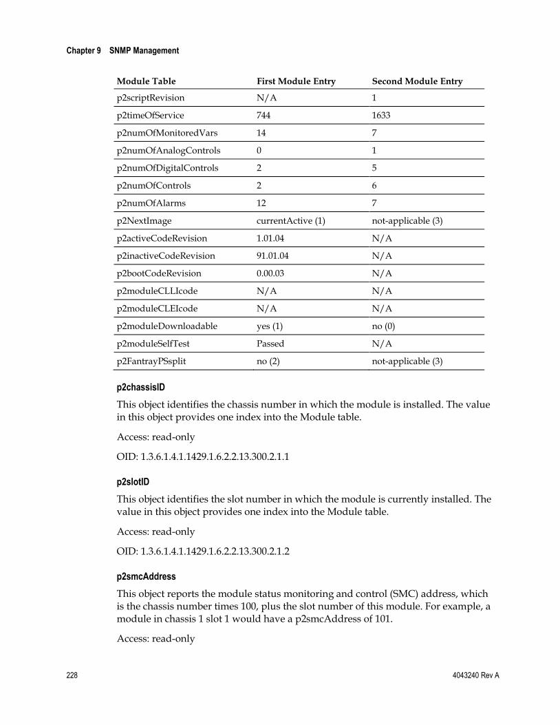
Chapter 9 SNMP Management
228 4043240 Rev A
Module Table First Module Entry Second Module Entry
p2scriptRevision N/A 1
p2timeOfService 744 1633
p2numOfMonitoredVars 14 7
p2numOfAnalogControls 0 1
p2numOfDigitalControls 2 5
p2numOfControls 2 6
p2numOfAlarms 12 7
p2NextImage currentActive (1) not-applicable (3)
p2activeCodeRevision 1.01.04 N/A
p2inactiveCodeRevision 91.01.04 N/A
p2bootCodeRevision 0.00.03 N/A
p2moduleCLLIcode N/A N/A
p2moduleCLEIcode N/A N/A
p2moduleDownloadable yes (1) no (0)
p2moduleSelfTest Passed N/A
p2FantrayPSsplit no (2) not-applicable (3)
p2chassisID
This object identifies the chassis number in which the module is installed. The value in this object provides one index into the Module table.
Access: read-only
OID: 1.3.6.1.4.1.1429.1.6.2.2.13.300.2.1.1
p2slotID
This object identifies the slot number in which the module is currently installed. The value in this object provides one index into the Module table.
Access: read-only
OID: 1.3.6.1.4.1.1429.1.6.2.2.13.300.2.1.2
p2smcAddress
This object reports the module status monitoring and control (SMC) address, which is the chassis number times 100, plus the slot number of this module. For example, a module in chassis 1 slot 1 would have a p2smcAddress of 101.
Access: read-only
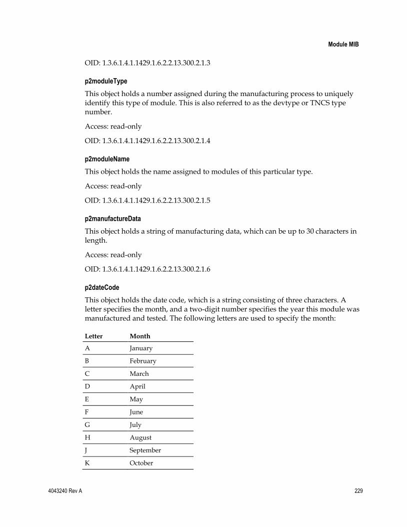
Module MIB
4043240 Rev A 229
OID: 1.3.6.1.4.1.1429.1.6.2.2.13.300.2.1.3
p2moduleType
This object holds a number assigned during the manufacturing process to uniquely identify this type of module. This is also referred to as the devtype or TNCS type number.
Access: read-only
OID: 1.3.6.1.4.1.1429.1.6.2.2.13.300.2.1.4
p2moduleName
This object holds the name assigned to modules of this particular type.
Access: read-only
OID: 1.3.6.1.4.1.1429.1.6.2.2.13.300.2.1.5
p2manufactureData
This object holds a string of manufacturing data, which can be up to 30 characters in length.
Access: read-only
OID: 1.3.6.1.4.1.1429.1.6.2.2.13.300.2.1.6
p2dateCode
This object holds the date code, which is a string consisting of three characters. A letter specifies the month, and a two-digit number specifies the year this module was manufactured and tested. The following letters are used to specify the month:
Letter Month
A January
B February
C March
D April
E May
F June
G July
H August
J September
K October

Chapter 9 SNMP Management
230 4043240 Rev A
Letter Month
L November
M December
Example: M07 = December 2007
Access: read-only
OID: 1.3.6.1.4.1.1429.1.6.2.2.13.300.2.1.7
p2serialNumber
The value in this object designates the module serial number.
Access: read-only
OID: 1.3.6.1.4.1.1429.1.6.2.2.13.300.2.1.8
p2coreCodeRevision
The value in this object is CF_CCB3 for downloadable CCBs designed to interface with the ICIM.
Access: read-only
OID: 1.3.6.1.4.1.1429.1.6.2.2.13.300.2.1.9
p2scriptRevision
This object is deprecated in the downloadable modules, which do not use scripts. It is retained for compatibility with previous versions of the modules, which still use scripts.
Access: read-only
OID: 1.3.6.1.4.1.1429.1.6.2.2.13.300.2.1.10
p2timeOfService
This object reports the number of hours this module has been in service. The value is updated every hour for the first 120 hours, and every 12 hours up to 120,000.
Access: read-only
OID: 1.3.6.1.4.1.1429.1.6.2.2.13.300.2.1.11
p2numOfMonitoredVars
The value in this object represents the total number of monitored variables for this module.
Access: read-only
OID: 1.3.6.1.4.1.1429.1.6.2.2.13.300.2.1.12

Module MIB
4043240 Rev A 231
p2numOfAnalogControls
The value in this object represents the total number of analog variables for this module.
Access: read-only
OID: 1.3.6.1.4.1.1429.1.6.2.2.13.300.2.1.13
p2numOfDigitalControls
The value in this object represents the total number of digital and state controls for this module.
Access: read-only
OID: 1.3.6.1.4.1.1429.1.6.2.2.13.300.2.1.14
p2numOfControls
The value in this object represents the total number of control variables for this module.
Access: read-only
OID: 1.3.6.1.4.1.1429.1.6.2.2.13.300.2.1.15
p2numOfAlarms
The value in this object represents the total number of alarm variables for this module.
Access: read-only
OID: 1.3.6.1.4.1.1429.1.6.2.2.13.300.2.1.16
p2NextImage
The value in this object represents the firmware image to be active following the module reboot. Options are currentActive (1), currentInactive (2), or not applicable (3).
Access: read-only
OID: 1.3.6.1.4.1.1429.1.6.2.2.13.300.2.1.17
p2activeCodeRevision
The value in this object represents the version of the firmware active for this module.
Access: read-only
OID: 1.3.6.1.4.1.1429.1.6.2.2.13.300.2.1.18

Chapter 9 SNMP Management
232 4043240 Rev A
p2inactiveCodeRevision
This object is reserved for future use.
Access: read-only
OID: 1.3.6.1.4.1.1429.1.6.2.2.13.300.2.1.19
p2bootCodeRevision
The value in this object represents the current boot image revision for the module.
Access: read-only
OID: 1.3.6.1.4.1.1429.1.6.2.2.13.300.2.1.20
p2moduleCLLIcode
This object is reserved for future use.
Access: read-write
OID: 1.3.6.1.4.1.1429.1.6.2.2.13.300.2.1.21
p2moduleCLEIcode
This object is reserved for future use.
Access: read-only
OID: 1.3.6.1.4.1.1429.1.6.2.2.13.300.2.1.22
p2moduleDownloadable
The value in this object indicates whether the module supports firmware downloads. The value may be either yes (1) or no (2).
Access: read-only
OID: 1.3.6.1.4.1.1429.1.6.2.2.13.300.2.1.23
p2moduleSelfTest
This object displays the results of the basic functional self-test that the module performs at boot-up or when inserted into a chassis slot. If the module passed the self-test, performing a get on this object returns the message “Self-Test Passed.” If the module encounters one or more problems, the message "Self-Test failed - Error Code” is returned followed by a decimal representation of the hexadecimal code of the failure(s).
Self-Test Error Codes: Prisma II Platform
The following error codes are used for the Prisma II Fan Tray, Pre-Amplifier, Post-Amplifier, and Optical Switch modules.

Module MIB
4043240 Rev A 233
Modules Test Failed Hexadecimal Code
Decimal Value
Flash bank 1 CRC 0x2000001 33554433
Flash bank 2 CRC 0x2000002 33554434
ColdFire RAM 0x2000004 33554436
Flash bank 0 CRC 0x2000008 33554440
EEPROM read 0x2000010 33554448
EEPROM write 0x2000020 33554464
EEPROM write-protect 0x2000040 33554496
SPI BUS 0x2000080 33554560
Local Craft Interface port 0x2000100 33554688
ICIM 485 port 0x2000200 33554944
Local Debug port 0x2000400 33555456
CAN BUS 0x2000800 33556480
Analog to Digital 0x2001000 33558528
Digital to Analog 0x2002000 33562624
IO 0x2004000 33570816
Power Supply 0x2008000 33587200
Self-Test Error Codes: Prisma II XD Platform
The following error codes are used for the Prisma II XD client control board, fan assembly, AC-to-DC bulk power supplies, DC-to-DC converters, ICIM, and installed application modules.
Modules Test Failed Hexadecimal Code
Decimal Value
Flash bank 1 CRC 0x2000001 33554433
Flash bank 2 CRC 0x2000002 33554434
ColdFire RAM 0x2000004 33554436
Flash bank 0 CRC 0x2000008 33554440
EEPROM read 0x2000010 33554448
EEPROM write 0x2000020 33554464
EEPROM write-protect 0x2000040 33554496
SPI BUS 0x2000080 33554560
Local Craft Interface port 0x2000100 33554688
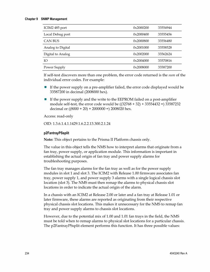
Chapter 9 SNMP Management
234 4043240 Rev A
ICIM2 485 port 0x2000200 33554944
Local Debug port 0x2000400 33555456
CAN BUS 0x2000800 33556480
Analog to Digital 0x2001000 33558528
Digital to Analog 0x2002000 33562624
IO 0x2004000 33570816
Power Supply 0x2008000 33587200
If self-test discovers more than one problem, the error code returned is the sum of the individual error codes. For example:
If the power supply on a pre-amplifier failed, the error code displayed would be 33587200 in decimal (2008000 hex).
If the power supply and the write to the EEPROM failed on a post-amplifier module self-test, the error code would be ((32768 + 32) + 33554432 =) 33587232 decimal or ((8000 + 20) + 2000000 =) 2008020 hex.
Access: read-only
OID: 1.3.6.1.4.1.1429.1.6.2.2.13.300.2.1.24
p2FantrayPSsplit
Note: This object pertains to the Prisma II Platform chassis only.
The value in this object tells the NMS how to interpret alarms that originate from a fan tray, power supply, or application module. This information is important in establishing the actual origin of fan tray and power supply alarms for troubleshooting purposes.
The fan tray manages alarms for the fan tray as well as for the power supply modules in slot 1 and slot 3. The ICIM2 with Release 1.00 firmware associates fan tray, power supply 1, and power supply 3 alarms with a single logical chassis slot location (slot 3). The NMS must then remap the alarms to physical chassis slot locations in order to indicate the actual origin of the alarm.
In a chassis with an ICIM2 at Release 2.00 or later and a fan tray at Release 1.01 or later firmware, these alarms are reported as originating from their respective physical chassis slot locations. This makes it unnecessary for the NMS to remap fan tray and power supply alarms to chassis slot locations.
However, due to the potential mix of 1.00 and 1.01 fan trays in the field, the NMS must be told when to remap alarms to physical slot locations for a particular chassis. The p2FantrayPSsplit element performs this function. It has three possible values:

Module MIB
4043240 Rev A 235
Value Meaning
Yes (1) This module is a newer fan tray (devtype 5012) or power supply (devtype 5013) with split data. Therefore, the data is only for the particular module (fan tray or power supply) you are viewing. The NMS does not need to perform slot remapping.
No (2) This module is an older fan tray-power supply combination (devtype 5010) with unsplit data. Therefore, the data needs to be separated into fan tray, power supply 1, and power supply 3. The NMS needs to perform slot remapping.
Not Applicable (3) This module is neither a power supply nor a fan tray module.
The default value of 3 (not applicable) tells the NMS that the module in alarm is neither the fan tray nor a power supply, making the issue moot. A value of 1 (Yes) means that the alarms are split by module, so alarm remapping is not needed. A value of 2 (No) means that the alarms are not split, so remapping is required.
Access: read-write
OID: 1.3.6.1.4.1.1429.1.6.2.2.13.300.2.1.25
Module Alarm Table
Currently, the alarms in the Module Alarm table and the corresponding traps generated by the alarm (or clear) condition are reported as Major or Minor with respect to severity level. See Alarm Severity Mappings (on page 241) for details concerning the alarm severity mappings.
The p2moduleAlarmTable OID is: 1.3.6.1.4.1.1429.1.6.2.2.13.300.5.
Note:
Alarm thresholds can only be adjusted for type 1, 2 and 7 alarms. (See the p2almType below.) The type of alarm is shown in the p2almType field. The p2almLimitAdjust field will be set to "enabled" if the limits can be adjusted, or to "disabled" if they cannot be adjusted.
The ICIM shows the alarm thresholds for all alarm types as read-writable, whether they can be adjusted or not. However, an error will result if the user attempts to change an alarm threshold with non-adjustable limits.
p2module Alarm Table
Entry 1 Entry 2 Entry 3 Entry 4 Entry 5
Instance 6.0.1 6.0.2 6.1.1 6.1.2 6.1.3
index * 1 2 1 2 3
label FansOk ChasTemp Ps1PwrIn Ps1+24 Ps1+5VDC
Value 1 (fault) 2 (ok) 0 (ok) 2 (ok) 2 (ok)

Chapter 9 SNMP Management
236 4043240 Rev A
p2module Alarm Table
Entry 1 Entry 2 Entry 3 Entry 4 Entry 5
Type 5 2 5 2 2
Nominal 1 25 1 24.7 5.4
Hysteresis na 1 na 0.1 0.1
Major Low na -40 na 18 3.6
Minor Low na -35 na 18.4 3.7
Minor High na 60 na 25.9 5.9
Major High na 65 na 26.1 6.1
Limit Adjust disabled (2) enabled (1) disabled (2) enabled (1) enabled (1)
Limit Range Lo na -32768 na -3276.8 -3276.8
Limit Range Hi na 32767 na 3276.7 3276.7
* The index value for the alarm is actually the third digit of the instance value. The alarm label will always have the same index value for that module. The index value is not a running index for the entire Module Alarm table.
p2almIndex
This object holds one of the indices into the alarm table. Indices include chassis and slot, as well as p2almIndex per alarm type for the module, which form the unique instance into the Module Alarm table.
Access: read-only
OID: 1.3.6.1.4.1.1429.1.6.2.2.13.300.5.1.1
p2almLabel
This object holds a string of eight characters or less that describes an alarm characteristic of a module type.
Access: read-only
OID: 1.3.6.1.4.1.1429.1.6.2.2.13.300.5.1.2
p2almValue
This object holds the alarm value, which may be a Boolean or Non-Boolean value as appropriate to the alarm type. The table below shows how the meanings of different alarm values vary depending on their class or enumeration (Non-Boolean vs. Boolean).
Class/Enumeration 0 1 2 3 4
Non-Boolean (p2almType 1, 2, 3, 4, 7, 8 - see table under palmType)
Major low
Minor low
OK Minor high
Major high

Module MIB
4043240 Rev A 237
Class/Enumeration 0 1 2 3 4
Boolean (p2almType 5 or 6) OK Fault na na na
Important: Certain alarm values can have very different meanings depending on the type of alarm. For example, for Boolean alarm types (p2almType = 5 or 6), p2almValue = 0 indicates that there is no fault (OK). However, for Non-Boolean alarm types (p2almType = 1, 2, 3, 4, 7, or 8), p2almValue = 0 indicates a major low alarm. See also p2almType below for more on alarm types.
Access: read-only
OID: 1.3.6.1.4.1.1429.1.6.2.2.13.300.5.1.3
p2almType
This object holds the alarm type. The alarm type is a number from 1 to 8 that identifies three key characteristics of the alarm:
Class - whether the alarm value is Boolean or Non-Boolean. This affects the way that the alarm values are interpreted.
Impact - whether the alarm thresholds are fixed by the module or can be changed by the user. A module alarm is controlled by the module. If a monitored value violates an alarm threshold set by a module, the module may shut down. User alarm thresholds may be configured by the user. However, these alarms will not cause modules to shut down.
Threshold Implementation - whether the threshold for the alarm is an absolute value, or is relative to one or more other control parameters.
The table below identifies the class, impact, and threshold implementation for each possible value of p2almType. Alarm types with user-adjustable thresholds are indicated with an asterisk (*) in the table and paragraphs below.
p2almType Class Impact Threshold Implementation
1 * Non-Boolean User Relative
2 * Non-Boolean User Absolute
3 Non-Boolean Module Relative
4 Non-Boolean Module Absolute
5 Boolean User na
6 Boolean Module na
7 * Non-Boolean User Absolute
8 Non-Boolean Module Absolute
* Only these alarm thresholds may be changed by a user.

Chapter 9 SNMP Management
238 4043240 Rev A
More on Alarm Types
A Major alarm for module alarm types 3, 4, and 6 below may shut down the module or an important feature of it, such as the laser, if a major threshold is violated. User alarms of type 1, 2, 5, and 7 will not shut down the module if a Major threshold (low or high) is exceeded.
1 The relative user alarm. The alarm thresholds are interpreted as a positive or negative value relative to the nominal value of the alarmed variable. The alarm thresholds can be adjusted by the operator, but this will not shut down the module.
2 The absolute user alarm. The alarm thresholds are interpreted as absolute values of the alarmed variable. The alarm thresholds can be adjusted by the operator, but this will not shut down the module.
3 The relative module alarm. The interpretation of thresholds is like type 1, but a Major Alarm will set the module in the safe state. The alarm thresholds are not user-adjustable.
4 The absolute module alarm. The interpretation of thresholds is like type 2, but a Major Alarm will set the module in the safe state. The alarm thresholds are not user-adjustable.
5 User Boolean alarm. The state 0 means no alarm (OK). The nominal set to 1 (see p2almNominal below) means that input signal of 1 causes an alarm. If nominal is 0, input value of 0 causes alarm. This alarm does not set the unit to the safe state. The alarm thresholds are not user-adjustable.
6 Module Boolean alarm. The state 0 means no alarm (OK). The nominal set to 1 (see p2almNominal below) means that input signal of 1 causes an alarm. If nominal is 0, input value of 0 causes alarm. This alarm will set the unit to the safe state. The alarm thresholds are not user-adjustable.
7 The user alarm with complete inhibit. Same as type 2 except that inhibiting this alarm will always put it in the no alarm state. It will not set anything to the safe state, set the alarm LED or relay or pull the attention line low. The alarm thresholds can be adjusted by the operator, but this will not shut down the module.
8 The Module alarm with complete inhibit. Same as type 7 except that the limits are not user adjustable. Unlike other module alarms it will not set anything to the safe set when an alarm is triggered. The alarm thresholds are not user-adjustable.
Important: The alarm type and alarm value are inseparably linked, in that the value may only be understood with respect to the type of alarm. (See also p2almValue above.)
Access: read-only
OID: 1.3.6.1.4.1.1429.1.6.2.2.13.300.5.1.4

Module MIB
4043240 Rev A 239
p2almNominal
This object holds the alarm nominal value. To view the current value for a particular module and element, see the Module Monitor table.
Access: read-only
OID: 1.3.6.1.4.1.1429.1.6.2.2.13.300.5.1.5
p2almHysteresis
This object defines the hysteresis value for the alarm. The hysteresis value determines how far from the alarm threshold a parameter must change before an alarm condition will clear. The purpose of hysteresis is to prevent the rapid setting and clearing of alarms that otherwise would occur when a parameter makes small fluctuations about the alarm threshold value.
For example, assume that the Minor High limit for chassis temperature is set to 45°C, and the hysteresis value for this alarm parameter is 1°C. When the chassis temperature rises above 45°C, the Minor High alarm occurs. In order for the alarm to clear, the temperature must fall below 44°C, which is the alarm threshold value of 45 minus the hysteresis value of 1.
Likewise, if the chassis temperature had a Minor Low alarm threshold of -20°C and a hysteresis value of 1°C, a Minor Low alarm would occur if the temperature fell below -20°C, but would not clear until the temperature rose above -19°C.
See Note at the end of this section for additional information.
Access: read-write
OID: 1.3.6.1.4.1.1429.1.6.2.2.13.300.5.1.8
p2almMajorLowLimit
This object holds the Major Low alarm threshold value. See Note at the end of this section for additional information.
Access: read-write
OID: 1.3.6.1.4.1.1429.1.6.2.2.13.300.5.1.9
p2almMinorLowLimit
This object holds the Minor Low alarm threshold value. See Note at the end of this section for additional information.
Access: read-write
OID: 1.3.6.1.4.1.1429.1.6.2.2.13.300.5.1.10

Chapter 9 SNMP Management
240 4043240 Rev A
p2almMinorHighLimit
This object holds the Minor High alarm threshold value. See Note at the end of this section for additional information.
Access: read-write
OID: 1.3.6.1.4.1.1429.1.6.2.2.13.300.5.1.11
p2almMajorHighLimit
This object holds the Major High alarm threshold value. See Note at the end of this section for additional information.
Access: read-write
OID: 1.3.6.1.4.1.1429.1.6.2.2.13.300.5.1.12
p2almLimitAdjust
The value in this object indicates whether an alarm has adjustable threshold values. It will be set to enabled (1) if adjustable, disabled (2) if non-adjustable. See Note at the end of this section for additional information.
Access: read-only
OID: 1.3.6.1.4.1.1429.1.6.2.2.13.300.5.1.13
p2almLimitRangeLo
The value in this object is the lower limit for an adjustable alarm threshold.
Access: read-only
OID: 1.3.6.1.4.1.1429.1.6.2.2.13.300.5.1.14
p2almLimitRangeHi
The value in this object is the upper limit for an adjustable alarm threshold.
Access: read-only
OID: 1.3.6.1.4.1.1429.1.6.2.2.13.300.5.1.15
Note: Alarm thresholds can only be adjusted for type 1, 2 and 7 alarms. The type of alarm is shown in the p2almType field. The p2almLimitAdjust field will be set to "enabled" if the limits can be adjusted, or to "disabled" if they cannot be adjusted.
The ICIM treats all modules the same in that the alarm thresholds will be shown as read-writable for all alarm types, whether they can be adjusted or not. An error will result if the user attempts to change an alarm threshold with non-adjustable limits.

Module MIB
4043240 Rev A 241
Alarm Severity Mappings
All Prisma II and Prisma II XD chassis alarms report to Major or Minor severity levels, as shown in the following tables.
Note: For additional information on alarms, alarm types, and alarm values, see Module Alarm Table (on page 235).
Prisma II Chassis - Fan Tray and Power Supplies
Alarm Type Severity Level
FansOk Minor
ChasTemp Major/Minor per threshold settings
Ps1PwrIn Major
Ps1+24 Major/Minor per threshold settings
Ps1+5VDC Major/Minor per threshold settings
Ps1-5VDC Major/Minor per threshold settings
Ps3PwrIn Major
Ps3+24 Major/Minor per threshold settings
Ps3+5VDC Major/Minor per threshold settings
Ps3-5VDC Major/Minor per threshold settings
Prisma II XD Chassis - Fan Assembly and Power Supplies
Alarm Type Severity Level
Fan 1_Ok Major
Fan 2_Ok Major
Fan 3_Ok Major
ChasTemp Major/Minor per threshold settings
ConvAIn Major
ConvA+24 Major/Minor per threshold settings
ConvA+5 Major/Minor per threshold settings
ConvA-5 Major/Minor per threshold settings
ConvBIn Major
ConvB+24 Major/Minor per threshold settings
ConvB+5 Major/Minor per threshold settings
ConvB-5 Major/Minor per threshold settings
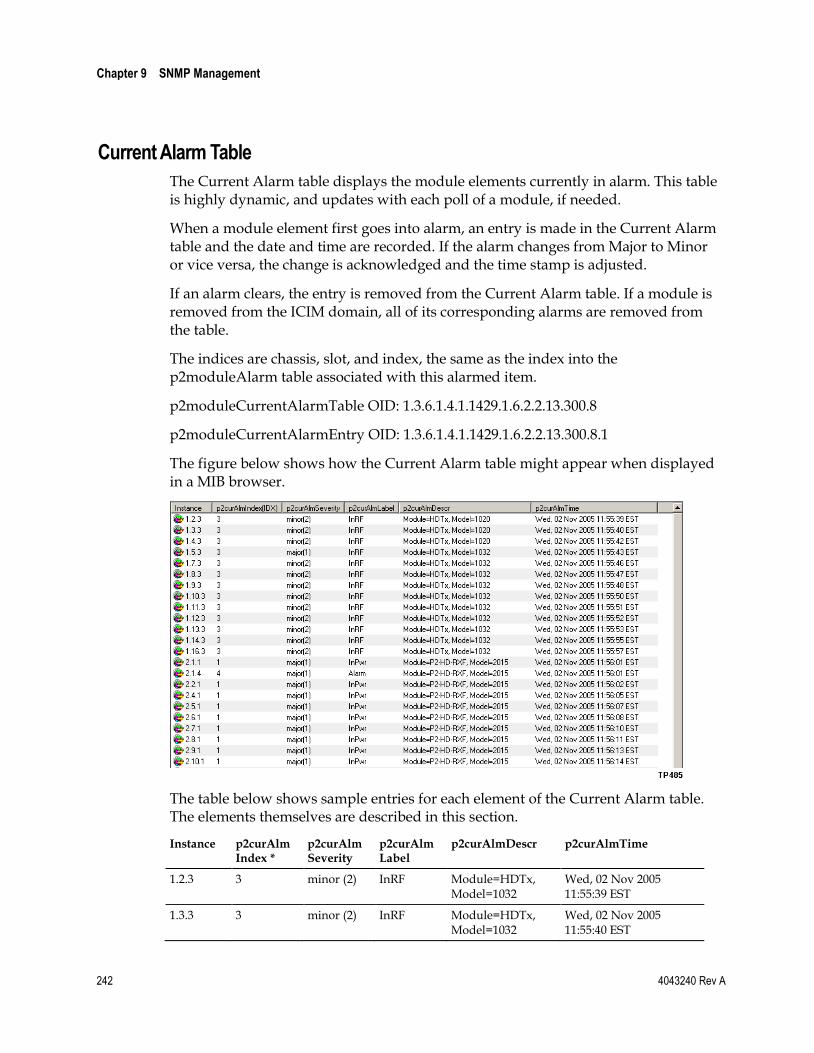
Chapter 9 SNMP Management
242 4043240 Rev A
Current Alarm Table
The Current Alarm table displays the module elements currently in alarm. This table is highly dynamic, and updates with each poll of a module, if needed.
When a module element first goes into alarm, an entry is made in the Current Alarm table and the date and time are recorded. If the alarm changes from Major to Minor or vice versa, the change is acknowledged and the time stamp is adjusted.
If an alarm clears, the entry is removed from the Current Alarm table. If a module is removed from the ICIM domain, all of its corresponding alarms are removed from the table.
The indices are chassis, slot, and index, the same as the index into the p2moduleAlarm table associated with this alarmed item.
p2moduleCurrentAlarmTable OID: 1.3.6.1.4.1.1429.1.6.2.2.13.300.8
p2moduleCurrentAlarmEntry OID: 1.3.6.1.4.1.1429.1.6.2.2.13.300.8.1
The figure below shows how the Current Alarm table might appear when displayed in a MIB browser.
The table below shows sample entries for each element of the Current Alarm table. The elements themselves are described in this section.
Instance p2curAlm Index *
p2curAlm Severity
p2curAlm Label
p2curAlmDescr p2curAlmTime
1.2.3 3 minor (2) InRF Module=HDTx, Model=1032
Wed, 02 Nov 2005 11:55:39 EST
1.3.3 3 minor (2) InRF Module=HDTx, Model=1032
Wed, 02 Nov 2005 11:55:40 EST

Module MIB
4043240 Rev A 243
Instance p2curAlm Index *
p2curAlm Severity
p2curAlm Label
p2curAlmDescr p2curAlmTime
1.4.3 3 minor (2) InRF Module=HDTx, Model=1032
Wed, 02 Nov 2005 11:55:42 EST
1.5.3 3 major (1) InRF Module=HDTx, Model=1032
Wed, 02 Nov 2005 11:55:43 EST
1.7.3 3 minor (2) InRF Module=HDTx, Model=1032
Wed, 02 Nov 2005 11:55:46 EST
1.8.3 3 minor (2) InRF Module=HDTx, Model=1032
Wed, 02 Nov 2005 11:55:47 EST
1.9.3 3 minor (2) InRF Module=HDTx, Model=1032
Wed, 02 Nov 2005 11:55:48 EST
1.10.3 3 minor (2) InRF Module=HDTx, Model=1032
Wed, 02 Nov 2005 11:55:50 EST
1.11.3 3 minor (2) InRF Module=HDTx, Model=1032
Wed, 02 Nov 2005 11:55:51 EST
1.12.3 3 minor (2) InRF Module=HDTx, Model=1032
Wed, 02 Nov 2005 11:55:52 EST
1.13.3 3 minor (2) InRF Module=HDTx, Model=1032
Wed, 02 Nov 2005 11:55:53 EST
1.14.3 3 minor (2) InRF Module=HDTx, Model=1032
Wed, 02 Nov 2005 11:55:55 EST
1.16.3 3 minor (2) InRF Module=HDTx, Model=1032
Wed, 02 Nov 2005 11:56:57 EST
2.1.1 1 minor (2) InPwr Module=P2-HD-RXF, Model=2015
Wed, 02 Nov 2005 11:56:01 EST
* The index value for the alarm is actually the third digit of the instance value. The alarm label will always have the same index value for that module. The index value is not a running index for the entire Current Alarm table.
p2curAlmIndex
The value in this object is the index into the p2moduleAlarm table for this object in alarm. It is one of three indices into the Current Alarm table, along with p2chassisID and p2slotID.
Access: read-only
OID: 1.3.6.1.4.1.1429.1.6.2.2.13.300.8.1.1
p2curAlmSeverity
The value in this object represents the current level of severity for the alarm shows here. The alarm may be Major (1) or Minor (2).
Access: read-only
OID: 1.3.6.1.4.1.1429.1.6.2.2.13.300.8.1.2

Chapter 9 SNMP Management
244 4043240 Rev A
p2curAlmLabel
The value in this object represents the label assigned to the alarm, which corresponds to the p2almLabel.
Example: Fan1_Ok
Access: read-only
OID: 1.3.6.1.4.1.1429.1.6.2.2.13.300.8.1.3
p2curAlmDescr
This object holds the alarm description, which is a concatenation of the module name and the model number in text form. It is exactly the same as p2TrapLogText, sent by the Enhanced traps and logged in the Trap Log table.
Example: Module=HDTx, Model=1032
Access: read-only
OID: 1.3.6.1.4.1.1429.1.6.2.2.13.300.8.1.4
p2curAlmTime
This object shows the time that the alarm was first recorded in the Current Alarm table, or the time that the severity level last changed from Major to Minor or vice versa.
Format Example: Wed, 02 Nov 2005 11:56:50 EST
Access: read-only
OID: 1.3.6.1.4.1.1429.1.6.2.2.13.300.8.1.5
Module Monitor Table
The Module Monitor table shows the actual values of module elements. Values may only be updated via a module in response to requests from the ICIM.
As with the Module Control table and the Module Alarm table, the Module Monitor table is indexed by the chassis and slot number of a particular module. The third index into the table is represented by the p2monitor Index value.
The OID of p2moduleMonitorTable is: 1.3.6.1.4.1.1429.1.6.2.2.13.300.7.
Rows may be accessed via p2moduleMonitorEntry OID: 1.3.6.1.4.1.1429.1.6.2.2.13.300.7.1.
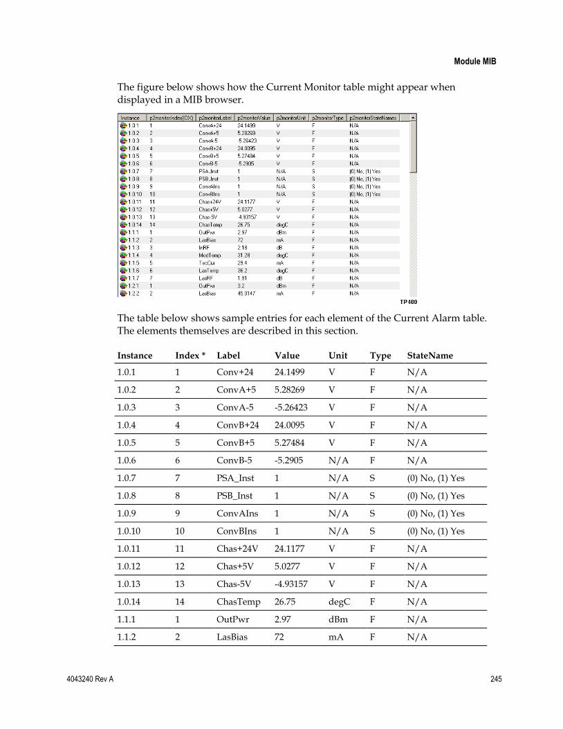
Module MIB
4043240 Rev A 245
The figure below shows how the Current Monitor table might appear when displayed in a MIB browser.
The table below shows sample entries for each element of the Current Alarm table. The elements themselves are described in this section.
Instance Index * Label Value Unit Type StateName
1.0.1 1 Conv+24 24.1499 V F N/A
1.0.2 2 ConvA+5 5.28269 V F N/A
1.0.3 3 ConvA-5 -5.26423 V F N/A
1.0.4 4 ConvB+24 24.0095 V F N/A
1.0.5 5 ConvB+5 5.27484 V F N/A
1.0.6 6 ConvB-5 -5.2905 N/A F N/A
1.0.7 7 PSA_Inst 1 N/A S (0) No, (1) Yes
1.0.8 8 PSB_Inst 1 N/A S (0) No, (1) Yes
1.0.9 9 ConvAIns 1 N/A S (0) No, (1) Yes
1.0.10 10 ConvBIns 1 N/A S (0) No, (1) Yes
1.0.11 11 Chas+24V 24.1177 V F N/A
1.0.12 12 Chas+5V 5.0277 V F N/A
1.0.13 13 Chas-5V -4.93157 V F N/A
1.0.14 14 ChasTemp 26.75 degC F N/A
1.1.1 1 OutPwr 2.97 dBm F N/A
1.1.2 2 LasBias 72 mA F N/A

Chapter 9 SNMP Management
246 4043240 Rev A
* The index value for the alarm is actually the third digit of the instance value. The monitor label will always have the same index value for that module. The index value is not a running index for the entire Module Monitor table.
p2monitorIndex
The value in this object is the third index into the Module Monitor table.
Access: read-only
OID: 1.3.6.1.4.1.1429.1.6.2.2.13.300.7.1.1
p2monitorLabel
This object holds a short description, eight characters or less, of the monitored variable found in the string associated with p2monitorLabel.
Access: read-only
OID: 1.3.6.1.4.1.1429.1.6.2.2.13.300.7.1.2
p2monitorValue
This object holds the monitor value, which is the actual value given by a module for the monitored variable.
Access: read-only
OID: 1.3.6.1.4.1.1429.1.6.2.2.13.300.7.1.3
p2monitorUnit
This object indicates the units assigned to the value appearing in p2monitorValue. The table below summarizes the common units used by monitored values and controls.
Unit Meaning
A amperes
dB decibels (10log10)
dBm decibels relative to 1 mW (0.0 dBm is 1.0 mW)
degC degrees in Centigrade
hrs hours
Inst installed
mA milliamperes
% percentage
sec seconds
Module MIB
4043240 Rev A 247
Access: read-only
OID: 1.3.6.1.4.1.1429.1.6.2.2.13.300.7.1.4
p2monitorType
This object indicates the monitor data type, represented with one of the following letters:
Unit Meaning
F floating point value
D digital, integer value
B Boolean, 0 or 1
L long, a floating point value converted to 8 ASCII Hex digits
S state with enumerated list of state names (up to 8 characters each)
Access: read-only
OID: 1.3.6.1.4.1.1429.1.6.2.2.13.300.7.1.5
p2monitorStateNames
If the element is a state variable, this object lists all the state names for the element.
Access: read-only
OID: 1.3.6.1.4.1.1429.1.6.2.2.13.300.7.1.6
Module Control Table
The Module Control table contains control information for every module in the ICIM domain that has control variables.
Like the Alarm table and Monitor table, the Control table has three indices:
Chassis number
Slot number
Individual index, which varies per module by control type
Collectively, these indices make up the instance into the table.
p2ModuleControlTable OID: 1.3.6.1.4.1.1429.1.6.2.2.13.300.6
p2ModuleControlEntry OID: 1.3.6.1.4.1.1429.1.6.2.2.13.300.6.1

Chapter 9 SNMP Management
248 4043240 Rev A
The figure below shows how the Module Control table might appear when displayed in a MIB browser.
The table below shows sample entries for each element of the Module Control table. The elements themselves are described in this section.
Instance Index * Label Value Unit Type Range Low
Range 1High
Range Step
StateNames
1.0.1 1 AlmMuteA 0 N/A S 0 1 1 (0) Off, (1) On
1.0.2 2 AlmMuteB 0 N/A S 0 1 1 (0) Off, (1) On
1.1.1 1 Enable 1 N/A B 0 1 1 N/A
1.1.2 2 CwMode 0 N/A B 0 1 1 N/A
1.1.3 3 LoRFInh 0 N/A B 0 1 1 N/A
1.1.4 4 Master 1 N/A S 0 1 1 (0) Slave, (1) Master
1.1.5 5 RFDrive 0 dB F -1.5 1.5 0.5 N/A
1.1.6 6 AGC 0 N/A B 0 1 1 N/A
1.2.1 1 Enable 1 N/A B 0 1 1 N/A
1.2.2 2 CwMode 0 N/A B 0 1 1 N/A
* The index value for the alarm is actually the third digit of the instance value. The alarm label will always have the same index value for that module. The index value is not a running index for the entire Module Control table.
p2cntrlIndex
The value in this object is one index into the Module Control table is the p2cntrlIndex. It is the third index; chassis and slot are the first and second indices to this table.
Access: read-only
OID: 1.3.6.1.4.1.1429.1.6.2.2.13.300.6.1.1
Module MIB
4043240 Rev A 249
p2cntrlLabel
This object holds a short description of the control, represented as a string of not more than eight characters. The description varies by module and its controls.
Access: read-only
OID: 1.3.6.1.4.1.1429.1.6.2.2.13.300.6.1.2
p2cntrlValue
The value in this object may be changed by the user to control an aspect of the module.
Access: read-write
OID: 1.3.6.1.4.1.1429.1.6.2.2.13.300.6.1.3
p2cntrlUnit
This object indicates the units assigned to the values appearing in p2cntrlValue. The table below summarizes the common units used by monitored values and controls.
Unit Meaning
A amperes
dB decibels (10log10)
dBm decibels relative to 1 mW (0.0 dBm is 1.0 mW)
degC degrees in Centigrade
hrs hours
Inst installed
mA milliamperes
% percentage
sec seconds
Access: read-only
OID: 1.3.6.1.4.1.1429.1.6.2.2.13.300.6.1.4
p2cntrlType
The value in this object represents the data type of the control variable:

Chapter 9 SNMP Management
250 4043240 Rev A
Unit Meaning
F floating point value
D digital, integer value
B Boolean, 0 or 1
S state with enumerated list of state names (up to 8 characters each)
Access: read-only
OID: 1.3.6.1.4.1.1429.1.6.2.2.13.300.6.1.5
p2cntrlRangeLo
The value in this object is the lower limit for the control.
Access: read-only
OID: 1.3.6.1.4.1.1429.1.6.2.2.13.300.6.1.6
p2cntrlRangeHi
The value in this object is the upper limit for the control.
Access: read-only
OID: 1.3.6.1.4.1.1429.1.6.2.2.13.300.6.1.7
p2cntrlRangeStep
The value in this object is the range step (smallest allowable increment) for the control.
Access: read-only
OID: 1.3.6.1.4.1.1429.1.6.2.2.13.300.6.1.8
p2cntrlStateNames
If the control is a state variable, this object will list the state names for the control.
Access: read-only
OID: 1.3.6.1.4.1.1429.1.6.2.2.13.300.6.1.9
Insert Module Table
If a module is inserted into the chassis following the initial polling of the ICIM, the module chassis and slot appear in the Insert Module table. The table is indexed sequentially by occurrence.
p2InsertModuleTable OID: 1.3.6.1.4.1.1429.1.6.2.2.13.300.3

Module MIB
4043240 Rev A 251
p2InsertModuleEntry OID: 1.3.6.1.4.1.1429.1.6.2.2.13.300.3.1
p2InsertModuleIndex
The value in this object is the index into the Insert Module table, which is sequential with respect to time.
Access: read-only
OID: 1.3.6.1.4.1.1429.1.6.2.2.13.300.3.1.1
p2InsertModuleChassisID
The value in this object represents the number of the chassis in which the module is installed.
Access: read-only
OID: 1.3.6.1.4.1.1429.1.6.2.2.13.300.3.1.2
p2InsertModuleSlotID
The value in this object represents the number of the slot in which the module is installed.
Access: read-only
OID: 1.3.6.1.4.1.1429.1.6.2.2.13.300.3.1.3
Remove Module Table
If a module is removed from a slot, some data concerning the module appears in the Remove Module table. Information captured in this table allows managers to determine if the removed module was replaced by a module of the same type. This table is indexed sequentially based on occurrence.
As with other tables for the module, the rows in this table may be accessed via the p2RemoveModuleEntry.
p2RemoveModuleTable OID: 1.3.6.1.4.1.1429.1.6.2.2.13.300.4
p2IRemoveModuleEntry OID: 1.3.6.1.4.1.1429.1.6.2.2.13.300.4.1
p2RemoveModuleIndex
The value in this object represents the index into the Remove Module table, which is sequential with respect to time.
Access: read-only
OID: 1.3.6.1.4.1.1429.1.6.2.2.13.300.4.1.1

Chapter 9 SNMP Management
252 4043240 Rev A
p2RemoveModuleChassisID
The value in this object represents the number of the chassis in which the module had been installed.
Access: read-only
OID: 1.3.6.1.4.1.1429.1.6.2.2.13.300.4.1.2
p2RemoveModuleSlotID
The value in this object represents the number of the slot in which the module had been installed.
Access: read-only
OID: 1.3.6.1.4.1.1429.1.6.2.2.13.300.4.1.3
p2RemoveModuleName
The value in this object represents the name assigned to this module type during the manufacturing process.
Access: read-only
OID: 1.3.6.1.4.1.1429.1.6.2.2.13.300.4.1.4
p2RemoveModuleType
The value in this object represents the number assigned during the manufacturing process to uniquely identify this type of module. This is also referred to as the devtype or TNCS type number.
Access: read-only
OID: 1.3.6.1.4.1.1429.1.6.2.2.13.300.4.1.5
p2RemoveModuleSerialNum
The value in this object designates the serial number of the removed module.
Access: read-only
OID: 1.3.6.1.4.1.1429.1.6.2.2.13.300.4.1.6
Remote Reboot of ICIM and Modules
4043240 Rev A 253
Remote Reboot of ICIM and Modules You can boot the ICIM and associated application modules remotely using a series of SNMP commands. The modules may be rebooted using a hard reboot (service interrupting) or a soft reboot (non-service interrupting). The ICIM always performs a hard reboot (non-service interrupting) in response to either a soft reboot or hard reboot command.
To Reboot the ICIM via SNMP
Complete the following steps to reset the ICIM via SNMP.
1 Set p2icimDownLdTgt to "ccss," where cc is the chassis number and ss is the slot number.
2 Set p2icimDownLdCmd to "9" (reboot enable).
3 Set p2icimDownLdCmd to "7" or "8" (7 for soft reboot, 8 for hard reboot).
Note:
For the ICIM2 and ICIM2-XD, the soft reboot and the hard reboot are the same.
An ICIM reboot clears the module database in the ICIM and requires rediscovery of the domain to update the module status. Discovery times may be as long as 5 minutes, depending on the system size and configuration.
To Reboot a Module via SNMP
Complete the following steps to reset an application module via SNMP.
1 Set p2icimDownLdTgt to "ccss," where cc is the chassis number and ss is the slot number.
2 Set p2icimDownLdCmd to "9" (reboot enable).
3 Set p2icimDownLdCmd to "7" or "8" (7 for soft reboot, 8 for hard reboot).
Note: A module soft reboot will not interrupt service to the end customer, but a hard reboot may cause a brief disruption of service.

Chapter 9 SNMP Management
254 4043240 Rev A
Prisma II Traps This section describes trap destination configuration and provides details on trap types, conditions causing traps, and trap logging.
About Traps
The Prisma II system can be configured to provide various alarm and warning conditions, called traps, to an element management system or system monitor application. Up to eight different traps can be enabled independently to provide information on events occurring in a system:
IP Change
Module Insertion
Module Removal
Alarm Event
Download Complete
Self-Test
Reboot
Enhanced Alarm
These traps can be sent to up to ten different IP addresses, or "users." Trap filtering can be configured independently for each user.
Each trap is accompanied by one or more bindings, which are parameters representing the physical or logical objects associated with the trap.
The following table briefly describes each of the traps listed above and identifies its associated bindings.
Trap Description Binding
IP Change Trap An informational event indicating when the ICIM IP address has been changed.
1. Previous IP address
Module Insertion Trap An informational event indicating that a module has been inserted into a chassis.
1. Chassis ID
2. Slot ID
Module Removal Trap An informational event indicating that a module has been removed from a chassis.
1. Chassis ID
2. Slot ID
Alarm Event Trap An informational event indicating that an alarm has changed state on a module.
1. Chassis ID
2. Slot ID
3. Alarm Table Index
4. Alarm Label (Description)

Prisma II Traps
4043240 Rev A 255
Trap Description Binding
Download Complete Trap
An informational event indicating that new application software has been downloaded to a module.
1. Chassis ID
2. Slot ID
Reboot Command Trap
An informational event indicating that a module has been commanded to reboot (hard or soft).
1. Chassis ID
2. Slot ID
Self-Test Trap An alarm indicating that a module has failed its power-on self test.
1. Chassis ID
2. Slot ID
Enhanced Alarm Trap An event indicating that an alarm has changed state or an event has occurred with a module. This trap includes additional bindings to indicate CLLI and CLEI codes for telecommunications equipment.
1. Trap Sequence Number
2. Severity
3. State
4. Description
5. OID
6. Module Name and type
7. Chassis ID
8. Slot ID
9. CLLI code
10. CLEI code
11. TimeStamp
12. Date Time Zone
13. Value
14. Unit
15. Description
Note: All trap types (module insertion, alarm events, etc.) are reported through the Enhanced Alarm trap. By default, only the Enhanced Alarm traps are enabled.
Trap Receiving Configuration
Trap receiving is configured in the p2TrapRecvTable.
Note: If the ICIM has IPsec enabled, the remote PC or workstation must be set up for IPsec and included in the ICIM list of IPsec peers. For detailed instructions, see Setting Up IPsec (on page 315).
OID: 1.3.6.1.4.1.1429.1.6.2.2.13.200.8
A sample view of this table is provided below.

Chapter 9 SNMP Management
256 4043240 Rev A
Object RX Trap RX Trap RX Trap RX Trap Example (same as RX Trap #3)
p2TrapRecvIndex 0 1 2 3 4 5 6 7 8 9
p2TrapRecvEnable enabled (2) disabled (1) disabled (1) disabled (1) 1 1 1 1 1 1
p2TrapRecvAddr 172.24.28.66 172.24.28.94 0.0.0.0 0.0.0.0 0 0 0 0 0 0
p2TrapRecvIPChange disabled (1) disabled (1) disabled (1) disabled (1) 1 1 1 1 1 1
p2TrapRecvModuleInsert disabled (1) disabled (1) disabled (1) disabled (1) 1 1 1 1 1 1
p2TrapRecvModuleRemove disabled (1) disabled (1) disabled (1) disabled (1) 1 1 1 1 1 1
p2TrapRecvMinorAlarm never (1) never (1) never (1) never (1) 1 1 1 1 1 1
p2TrapRecvMajorAlarm never (1) never (1) never (1) never (1) 1 1 1 1 1 1
p2TrapRecvDwnLdComplete disabled (1) disabled (1) disabled (1) disabled (1) 1 1 1 1 1 1
p2TrapRecvRebootCommand disabled (1) disabled (1) disabled (1) disabled (1) 1 1 1 1 1 1
p2TrapRecvSelfTest disabled (1) disabled (1) disabled (1) disabled (1) 1 1 1 1 1 1
p2TrapRecvTelcoAlarm enabled (2) enabled (2) enabled (2) enabled (2) 2 2 2 2 2 2
As shown in the table, the traps can be filtered for each of the 10 trap receiving addresses. It is important to note that if p2TrapRecvEnable is set to "disabled," no enterprise specific traps will be sent to that IP address even if the individual filters are enabled.
The recommended (and default) trap configuration is to only enable p2TrapRecvTelcoAlarm traps. The other traps are also reported through this trap type. Enabling p2TrapRecvTelcoAlarms along with other trap types will result in duplicate traps for a single alarm event. The trap type filtering remains in place in order to support legacy systems.
To Configure Trap Destination
By setting the objects in the Trap Recv table, you can enable traps to be sent to up to 10 different IP addresses. The index into the table represents one of 10 rows, designated 0 to 9.
Complete the following steps to receive traps.
1 Set p2TrapRecvEnable to enabled (2), which allows traps to be sent to the IP address on the same row.
2 Set the IP address of the remote entity to receive traps. Use the format 172.18.2.24.
Note: If the ICIM has IPsec enabled, all trap receivers must be set up for IPsec and added to the ICIM list of IPsec peers. For detailed instructions, see Setting Up IPsec (on page 315).
3 Set p2TrapRecvTelcoAlarm to enabled (2).
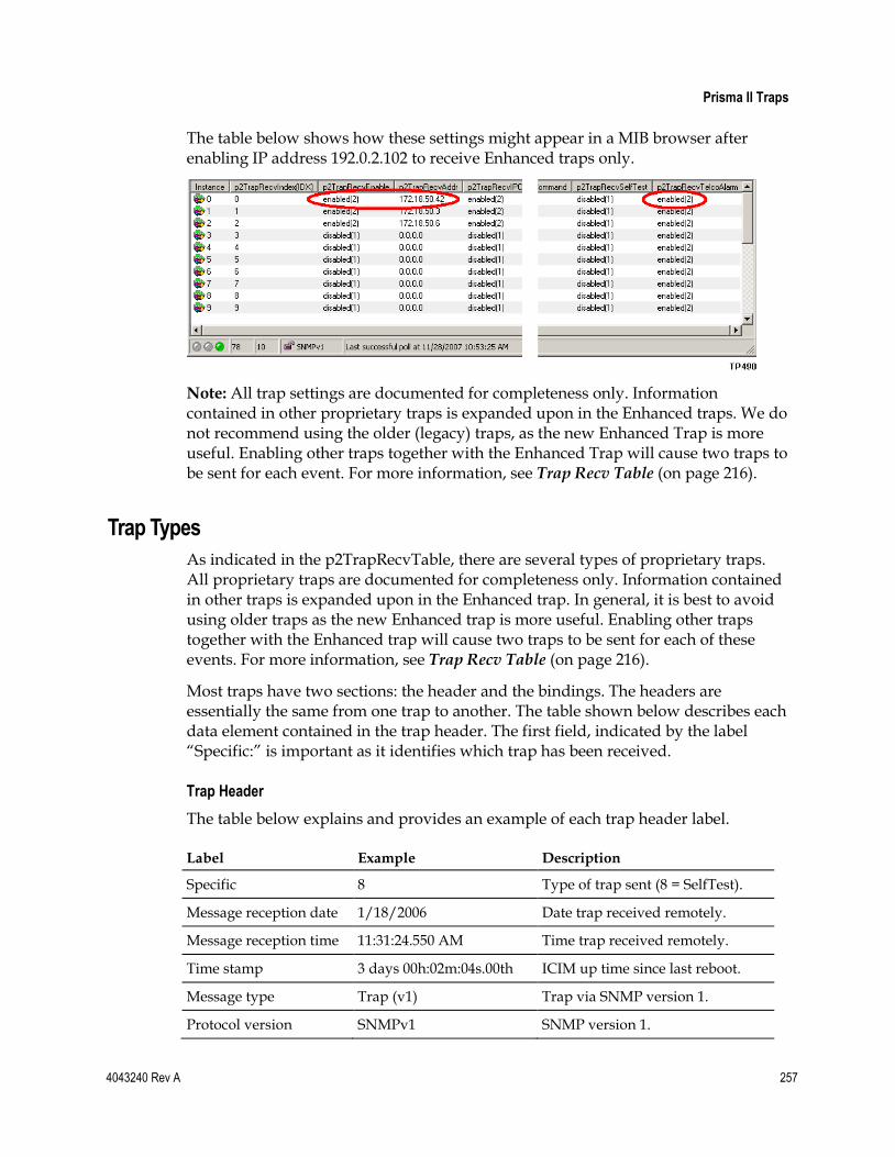
Prisma II Traps
4043240 Rev A 257
The table below shows how these settings might appear in a MIB browser after enabling IP address 192.0.2.102 to receive Enhanced traps only.
Note: All trap settings are documented for completeness only. Information contained in other proprietary traps is expanded upon in the Enhanced traps. We do not recommend using the older (legacy) traps, as the new Enhanced Trap is more useful. Enabling other traps together with the Enhanced Trap will cause two traps to be sent for each event. For more information, see Trap Recv Table (on page 216).
Trap Types
As indicated in the p2TrapRecvTable, there are several types of proprietary traps. All proprietary traps are documented for completeness only. Information contained in other traps is expanded upon in the Enhanced trap. In general, it is best to avoid using older traps as the new Enhanced trap is more useful. Enabling other traps together with the Enhanced trap will cause two traps to be sent for each of these events. For more information, see Trap Recv Table (on page 216).
Most traps have two sections: the header and the bindings. The headers are essentially the same from one trap to another. The table shown below describes each data element contained in the trap header. The first field, indicated by the label “Specific:” is important as it identifies which trap has been received.
Trap Header
The table below explains and provides an example of each trap header label.
Label Example Description
Specific 8 Type of trap sent (8 = SelfTest).
Message reception date 1/18/2006 Date trap received remotely.
Message reception time 11:31:24.550 AM Time trap received remotely.
Time stamp 3 days 00h:02m:04s.00th ICIM up time since last reboot.
Message type Trap (v1) Trap via SNMP version 1.
Protocol version SNMPv1 SNMP version 1.

Chapter 9 SNMP Management
258 4043240 Rev A
Label Example Description
Transport IP/UDP Transport protocol used.
Agent
Address
Port
172.24.28.168
162
IP address of the ICIM.
ICIM port.
Manager
Address
Port
172.18.43.3
162
Remote IP address.
Remote port.
Community prismatrap SNMP trap community.
SNMPv1 agent address 172.24.28.168 IP address of the ICIM.
Enterprise p2trapEvents MIB associated with overall trap generation.
Bindings (2) 2 Number of bindings to follow.
The number following the word Specific indicates the type of trap sent. The possible values and meanings of this number are as follows:
Unit Meaning
2 Insert Module
3 Remove Module
4 Alarm (Major or Minor, Alarm or Clear)
5 IP Change Event
6 Download Complete (reserved for future use)
7 Reboot Command
8 SelfTest Failure
9 Telco Alarm
At least one binding follows the header. The Enhanced traps include 15 bindings carrying information regarding the entity that caused the trap to be sent. For more information on Enhanced traps, see Enhanced Trap Binding Information (on page 268).
Other proprietary traps send very basic data, such as the chassis and slot of the ICIM or application module.

Prisma II Traps
4043240 Rev A 259
Trap Binding Example
The table below explains and provides an example of trap bindings.
Binding MIB Name (Examples) Explanation
1: ChassisID p2chassisID Chassis where the ICIM or application module is installed.
2: SlotID p2slotID Slot where the ICIM or application module is installed.
3: Self-Test data p2moduleSelfTest SelfTest Failed - Error code value.
IP Change Trap (Specific: 5)
This trap is sent when an ICIM IP address is changed through the CLI. If p2TrapRecvIPChange is set to enabled (2), a trap containing the previous IP will be sent. The new IP address will take effect on the next ICIM reboot.
Note: Documentation on this trap is included for completeness. All information in this trap is contained in and expanded upon in the Enhanced trap. We recommend using the Enhanced trap instead of this trap, as the Enhanced trap is more useful. Enabling this trap together with the Enhanced trap will cause two traps to be sent for each triggering event.
Specific: 5 appears in the heading to indicate that this is an IP Change trap. The table below describes the binding.
Binding MIB Name (Examples) Explanation
1: PreviousIP p2PreviousIP The IP address previously given to the ICIM before a new IP address was assigned. The new IP address takes effect upon the next ICIM reboot.
IP Change Trap Example
Specific: 5 Message reception date: 1/31/2006 Message reception time: 1:19:58.793 PM Time stamp: 3 days 00h:25m:57s.00th Message type: Trap (v1) Protocol version: SNMPv1 Transport: IP/UDP Agent Address: 172.24.28.168 Port: 1051 Manager Address: 172.18.4.23 Port: 162 Community: prismatrap SNMPv1 agent address: 172.24.28.168 Enterprise: p2trapEvents Bindings (1) Binding #1: p2PreviousIP.0 (ipaddr) 172.24.28.168

Chapter 9 SNMP Management
260 4043240 Rev A
Module Insert Trap (Specific: 2)
This trap is sent as soon as the ICIM discovers that a module has been inserted. If p2TrapRecvModuleInsert is enabled (2), a trap containing the chassis and slot of the new module is sent. A number appears in the heading indicating that this is a module insert trap.
Note: Documentation on this trap is included for completeness. All information in this trap is contained in and expanded upon in the Enhanced trap. We recommend using the Enhanced trap instead of this trap, as the Enhanced trap is more useful. Enabling this trap together with the Enhanced trap will cause two traps to be sent for each triggering event.
Specific: 2 appears in the heading to indicate that this is an InsertRemove trap. The table below describes the bindings.
Binding MIB Name (Examples) Explanation
1: ChassisID p2InsertModuleChassisID Chassis where the module is installed.
2: SlotID p2InsertModuleSlotID Slot where the module is installed.
Module Insert Trap Example
Specific: 2 Message reception date: 1/31/2006 Message reception time: 1:24:47.626 PM Time stamp: 3 days 00h:30m:46s.00th Message type: Trap (v1) Protocol version: SNMPv1 Transport: IP/UDP Agent Address: 172.24.28.168 Port: 1055 Manager Address: 172.18.4.28 Port: 162 Community: prismatrap SNMPv1 agent address: 172.24.28.168 Enterprise: p2trapEvents Bindings (2) Binding #1: p2InsertModuleChassisID.1 (int32) 2 Binding #2: p2InsertModuleSlotID.1 (int32) 13
Module Remove Trap (Specific: 3)
This trap is sent when the ICIM discovers that a module has been removed from the chassis. If p2TrapReceiveModuleRemove is enabled (2), a trap with the chassis and slot where the removed module had been installed will be sent.
Note: Documentation on this trap is included for completeness. All information in this trap is contained in and expanded upon in the Enhanced trap. We recommend using the Enhanced trap instead of this trap, as the Enhanced trap is more useful. Enabling this trap together with the Enhanced trap will cause two traps to be sent for each triggering event.
Specific: 3 appears in the heading to indicate that this is a ModuleRemove trap. The table below describes the bindings.

Prisma II Traps
4043240 Rev A 261
Binding MIB Name (Examples) Explanation
1: ChassisID p2RemoveModuleChassisID Chassis where the module was formerly installed.
2: SlotID p2RemoveModuleSlotID Slot where the module was formerly installed.
Module Remove Trap Example
Specific: 3 Message reception date: 1/31/2006 Message reception time: 1:27:35.778 PM Time stamp: 3 days 00h:33m:35s.00th Message type: Trap (v1) Protocol version: SNMPv1 Transport: IP/UDP Agent Address: 172.24.28.168 Port: 1060 Manager Address: 172.18.4.23 Port: 162 Community: prismatrap SNMPv1 agent address: 172.24.28.168 Enterprise: p2trapEvents Bindings (2) Binding #1: p2RemoveModuleChassisID.1 (int32) 2 Binding #2: p2RemoveModuleSlotID.1 (int32) 11
Alarm Traps (Specific: 4)
Alarm traps are edge triggered, meaning that whenever an alarm changes state, a trap is sent. An alarm changes state when a monitored value exceeds a limit set by an alarm threshold, or when a monitored Boolean parameter value changes from OK to Fault. Both of these events will generate alarms.
Alarms may trigger Major or Minor alarm traps, depending on the type of alarm limit that was exceeded. A Major alarm trap is sent when the monitored value exceeds the Major High or a Major Low alarm threshold. A Minor alarm trap is sent when the monitored value exceeds the Minor High or Minor Low alarm threshold.
Major and Minor alarm traps affect the ICIM polling cycle in different ways, as follows:
If an alarm is Minor, the module in alarm sends a trap to the ICIM after the next polling interval. Minor alarm handling is integral to the polling process, and does not disrupt the normal polling cycle.
If an alarm is Major, the module in alarm brings the ICIM Attention line low to request immediate service. In response, the ICIM first identifies the module requesting attention, and then polls the module to obtain the alarm information. After handling the Major alarm, the ICIM resets the polling process, so that it resumes at the beginning of the cycle, rather than at the point in the cycle at which it was interrupted.
Chapter 9 SNMP Management
262 4043240 Rev A
To configure alarm traps in the p2TrapRecvTable, select values for p2TrapRecvMajorAlarm or p2TrapRecvMinorAlarm. If traps are to be sent when monitored values exceed their Major Low or Major High threshold values, configure p2TrapRecvMajorAlarm. If traps are to be sent when monitored values exceed their Minor Low or Minor High threshold values, set values in p2TrapRecvMinorAlarm.
Note: A monitor value stated in a trap binding is a snapshot in time, and so may not indicate a value consistent with an alarm condition. If in doubt, verify the actual monitor value using the appropriate equipment interfaces.
The user may configure alarm trap behavior by selecting one of four options:
Never (1), meaning that traps of this type should never be sent
Clear (2), meaning that traps should be sent only when alarms are cleared
Set (3), meaning that traps should be sent only when alarms are set
Always (4), meaning that traps should be sent when alarms are set or cleared
Note: Documentation on this trap is included for completeness. All information in this trap is contained in and expanded upon in the Enhanced trap. We recommend using the Enhanced trap instead of this trap, as the Enhanced trap is more useful. Enabling this trap together with the Enhanced trap will cause two traps to be sent for each triggering event.
Specific: 4 appears in the heading to indicate an Alarm trap. (Specific: 4 as a value indicates a major alarm or clear, or a minor alarm or clear condition.) The table below describes the bindings.
Binding MIB Name (Examples) Explanation
1: ChassisID p2chassisID Chassis where the module is installed.
2: SlotID p2slotID Slot where the module is installed.
3: Index p2almIndex The index into the alarm table where more information may be found.
4: Label p2almLabel Label for the element that is in the state of alarm, e.g., ConvA+24.

Prisma II Traps
4043240 Rev A 263
Alarm Trap Example
Specific: 4 Message reception date: 1/31/2006 Message reception time: 1:31:58.829 PM Time stamp: 3 days 00h:37m:58s.00th Message type: Trap (v1) Protocol version: SNMPv1 Transport: IP/UDP Agent Address: 172.24.28.168 Port: 1074 Manager Address: 172.18.4.23 Port: 162 Community: prismatrap SNMPv1 agent address: 172.24.28.168 Enterprise: p2trapEvents Bindings (4) Binding #1: p2chassisID.2.3 (int32) 2 Binding #2: p2slotID.2.3 (int32) 3 Binding #3: p2almIndex.2.3.4 (int32) 4 Binding #4: p2almLabel.2.3.4 (octets) Ps1+24
Download Complete Trap (Specific: 6)
When a download to the ICIM or application module completes, a trap is sent. To enable this trap type, set p2TrapRecvDwnLdComplete to enabled (2).
Note: Documentation on this trap is included for completeness. All information in this trap is contained in and expanded upon in the Enhanced trap. We recommend using the Enhanced trap instead of this trap, as the Enhanced trap is more useful. Enabling this trap together with the Enhanced trap will cause two traps to be sent for each triggering event.
Specific: 6 appears in the heading to indicate a RebootCommand trap. The table below describes the bindings.
Binding MIB Name (Examples) Explanation
1: ChassisID p2chassisID Chassis where the ICIM or application module is installed.
2: SlotID p2slotID Slot where the ICIM or application module is installed.

Chapter 9 SNMP Management
264 4043240 Rev A
Download Complete Trap Example
Specific: 6 Message reception date: 1/31/2006 Message reception time: 1:45:19.299 PM Time stamp: 3 days 00h:51m:21s.00th Message type: Trap (v1) Protocol version: SNMPv1 Transport: IP/UDP Agent Address: 172.24.28.168 Port: 1141 Manager Address: 172.18.4.23 Port: 162 Community: prismatrap SNMPv1 agent address: 172.24.28.168 Enterprise: p2trapEvents Bindings (2) Binding #1: p2chassisID.2 (int32) 2 Binding #2: p2slotID.2 (int32) 3
Reboot Command Trap (Specific: 7)
When the ICIM or application module receives the command to reboot, a trap is generated. If this reboot command is generated via the SOUP application, a broadcast reboot is sent out. In this case, only one trap may be generated for the ICIM and all modules under its management. To configure the reboot command trap to be sent, set p2TrapRecvRebootCommand to enabled (2).
Note: Documentation on this trap is included for completeness. All information in this trap is contained in and expanded upon in the Enhanced trap. We recommend using the Enhanced trap instead of this trap, as the Enhanced trap is more useful. Enabling this trap together with the Enhanced trap will cause two traps to be sent for each triggering event.
Specific: 7 appears in the heading to indicate a RebootCommand trap. The table below describes the bindings.
Binding MIB Name (Examples) Explanation
1: ChassisID p2chassisID Chassis where the ICIM or application module is installed.
2: SlotID p2slotID Slot where the ICIM or application module is installed.
The example below shows the bindings for a broadcast RebootCommand trap. Chassis 99 and slot 99 indicate that the reboot command was broadcast to all modules.

Prisma II Traps
4043240 Rev A 265
Reboot Command Trap Example
Specific: 7 Message reception date: 1/31/2006 Message reception time: 1:47:14.920 PM Time stamp: 3 days 00h:53m:16s.00th Message type: Trap (v1) Protocol version: SNMPv1 Transport: IP/UDP Agent Address: 172.24.28.168 Port: 1145 Manager Address: 172.18.4.23 Port: 162 Community: prismatrap SNMPv1 agent address: 172.24.28.168 Enterprise: p2trapEvents Bindings (2) Binding #1: p2chassisID.99 (int32) 99 Binding #2: p2slotID.99 (int32) 99
Self-Test Trap (Specific: 8)
This trap is sent if the ICIM or application module fails the self-test. The trap contains an error code, which is module specific. See the sections on p2icimSelfTest in ICIM MIB and p2moduleSelfTest in Module MIB for further discussion of the error codes. To receive the SelfTest traps, set p2TrapRecvSelfTest to enabled (2).
Note: Documentation on this trap is included for completeness. All information in this trap is contained in and expanded upon in the Enhanced trap. We recommend using the Enhanced trap instead of this trap, as the Enhanced trap is more useful. Enabling this trap together with the Enhanced trap will cause two traps to be sent for each triggering event.
Specific: 8 appears in the heading to indicate a SelfTest trap. The table below describes the bindings.
Binding MIB Name (Examples) Explanation
1: ChassisID p2chassisID Chassis where ICIM or application module is installed.
2: SlotID p2slotID Slot where the ICIM or application module is installed.
3: Self-Test data p2moduleSelfTest SelfTest Failed - Error Code value.

Chapter 9 SNMP Management
266 4043240 Rev A
Self-Test Trap Example
Specific: 8 Message reception date: 1/31/2006 Message reception time: 2:22:20.190 PM Time stamp: 3 days 00h:00m:20s.00th Message type: Trap (v1) Protocol version: SNMPv1 Transport: IP/UDP Agent Address: 172.24.28.168 Port: 1025 Manager Address: 172.18.4.23 Port: 162 Community: prismatrap SNMPv1 agent address: 172.24.28.168 Enterprise: p2trapEvents Bindings (3) Binding #1: p2chassisID.2 (int32) 2 Binding #2: p2slotID.2 (int32) 15 Binding #3: p2moduleSelfTest.2.15 (octets) SelfTest Failed - Error Code 32.
Enhanced Traps (Specific: 9)
The Enhanced traps summarize information for all trap types, with additional data, exclusive of all other traps. Also, if an alarm exists upon startup or module insertion, Enhanced traps will be sent. To configure the Enhanced traps, set p2TrapRecvTelcoAlarm to enabled (2).
Specific: 9 appears in the heading to indicate an Enhanced trap. The table below describes the bindings.
Example of Bindings
Trap Binding MIB Name (Examples) Explanation
1 Sequence p2TrapLogSequence Tracking number from 1 to 2,147,483,647.
2 Severity p2TrapLogSeverity Trap severity level - major (1), minor (2), warning (3).
3 State p2TrapLogState State - alarm (1), clear (2), event (3).
4 Label p2TrapLogLabel or
p2almLabel.1.3.4
Event Name or
Alarm Label.
5 OID p2almIndex.1.3 or
p2icimStatusMsg
More data regarding the alarm or event is found at this OID.
6 Text p2TrapLogText Module name and model number of ICIM.
7 ChassisID p2icimChassisID Chassis where the ICIM or application module is installed.
8 SlotID p2icimSlotID Slot where the ICIM or application module is installed.
9 CLLIcode p2icimCLLIcode Reserved for future use.
10 CLEIcode p2icimCLEIcode Reserved for future use.

Prisma II Traps
4043240 Rev A 267
Trap Binding MIB Name (Examples) Explanation
11 Time p2TrapLogTime Time trap generated in the format: YYYY-MM-DD, HH:MM:SS.ss
12 DateTime p2TrapLogDateTime Date and time generated in the format: DOW, DD MM YYYY HH:MM:SS ZZZ
13 Value p2TrapLogValue Monitored value of the object in alarm.
14 Units p2TrapLogUnit Monitored units of the value in alarm.
15 Description p2TrapLogDesc Verbose description of the alarm or event.
Example
Binding #1: p2TrapLogSequence *** (int32) 6 Binding #2: p2TrapLogSeverity *** (int32) major(1) Binding #3: p2TrapLogState *** (int32) alarm(1) Binding #4: p2almLabel.0.11.2 *** (octets) OutPwrA Binding #5: p2almIndex.0.11 *** (int32) 2 Binding #6: p2TrapLogText *** (octets) Module=1550nm Post-Amp FTTP,Model=3031 Binding #7: p2chassisID.0.11 *** (int32) 0 Binding #8: p2slotID.0.11 *** (int32) 11 Binding #9: p2moduleCLLIcode.0.11 *** (octets)SCIATL01 Binding #10: p2moduleCLEIcode.0.11 *** (octets) PostAmpCLEI Binding #11: p2TrapLogTime *** (octets) 2006-8-22,15:45:38.11 Binding #12: p2TrapLogDateTime *** (octets) Tue, 22 Aug 2006 15:45:38 EST Binding #13: p2TrapLogValue *** (octets) -50 Binding #14: p2TrapLogUnit *** (octets) dBm Binding #15: p2TrapLogDescr *** (octets) Optical output power of bank A exceeds major threshold (1550nm)
Trap Generation
Proprietary traps are generated as described above for edge triggered alarms or clear alarms (meaning a change in state of an alarm), as well as for any of the following events:
Changing the IP address of an ICIM
Inserting or removing a module
Successful completion of a download
Reboot of ICIM or application module
Failure of an ICIM or application module self-test
Additionally, the Enhanced traps are generated if an alarm condition exists in one of the modules upon startup or module insertion.

Chapter 9 SNMP Management
268 4043240 Rev A
Trap Logging
When an Enhanced trap is sent, a copy is also kept in the Trap Logging table. Each trap has a unique sequence number which may be used as the index into the Trap Logging table. All bindings captured in the Enhanced traps are also logged, and may be accessed in the event of network failures between the SNMP manager and the ICIM. The log retains up to 1,000 most recent Enhanced traps.
The figure below shows how the Trap Logging table might appear when displayed in a MIB browser.
Note: At least one row in p2TrapRecvTable must be configured and enabled and p2TrapRecvTelcoAlarm enabled (2) for logging of traps to occur automatically. For details, see To Configure Trap Destination (on page 256).
Enhanced Trap Binding Information
The Enhanced trap type was originally added to support the Telco requirement to include a trap sequence number (p2TrapLogSequence) binding. In addition, the Enhanced trap type includes other bindings to convey complete alarm information.
Important: The default and recommended configuration is to enable only the Enhanced trap type. Enabling Enhanced alarm traps and other trap types at the same time may result in duplicate traps being sent to the element management system. These other trap types remain to allow backward compatibility with previously deployed systems.
The table below provides a descriptive listing of the Enhanced trap bindings.
Trap Binding Description
1 p2TrapLogSequence A unique number assigned to each trap as it is generated. Serves as an index into the Trap Logging table.

Prisma II Traps
4043240 Rev A 269
Trap Binding Description
2 p2TrapLogSeverity The number assigned as a guide to prioritizing trap generating conditions. Severity may be major (1), minor (2), or warning (3).
3 p2TrapLogState State, along with severity, quickly gives a view into the current state of an entity. State may be alarm (1), clear (2), or event (3).
4 p2almLabel
p2TrapLogLabel
For an alarm or clear trap, the label is the same as the p2almLabel assigned to the condition that caused the trap, e.g. ChasTemp. For events, the type of event that sent the trap is identified as DownloadComplete, RebootCommand, SelfTest, AuthentictnFailed, AdminChange, LogMenuHalfFull, LogMenuFull, LoginThreshold, SNTP, UpdateChassisIDs, or UserLockout.
5 p2almIndex
p2InsertModuleEntry
p2icimStatusMsg
p2RemoveModuleEntry
p2ModuleSelfTest
p2icimSelfTest
p2icimIPAddr
More information regarding the trap may be found at the OID specified in this element. For an alarm or clear trap, this may be the third index into the Module Alarm table. For the download, reboot, or self-test event, this may be the p2icimStatusMessage. However, the ICIM retains only the most recent status message.
If a message generated by another event overwrites the status message, additional information may no longer be available at the OID specified for the particular trap. If an event is logged, event details may be saved in the event log.
6 p2TrapLogText Display string which further describes the entity or condition responsible for trap generation. This usually is a concatenation of the module name and module number, although it may include the self-test failure code.
7 p2icimChassisID
p2chassis
Chassis in which the ICIM or application module resides at the time of trap generation.
8 p2icimSlotID
p2slotID
Slot number in which the ICIM or application module resides at the time of trap generation.
9 p2icimCLLIcode Reserved for future use.
10 p2icimCLEIcode Reserved for future use.
11 p2TrapLogTime Date and time stamp indicating when the trap was generated.

Chapter 9 SNMP Management
270 4043240 Rev A
Trap Binding Description
12 p2TrapLogDateTime Full local time displayed in the format: DOW, DD MMM YYYY HH:MM:SS ZZZ
Note: The local time zone must be entered in p2icimTimeZone or the default time zone, EST, will show.
13 p2TrapLogValue Monitored value of the object in alarm.
14 p2TrapLogUnit Monitored units of the value in alarm.
15 p2TrapLogDescr Verbose description of the alarm or event.
Trap Sequence Numbering
To observe the most current sequence number used by the Enhanced traps, perform a get operation on this OID. If no traps have been sent, the p2TrapLastSequenceNumber is 0. Valid sequence numbers are 1 through 2,147,483,647. The sequence number resets to 1 with the first trap sent after the ICIM boots up, or the p2TrapLogEntry table is cleared with the p2TrapLogClearKey, or with the trap following sequence number 2,147,483,647.
OID: 1.3.6.1.4.1.1429.1.6.2.2.13.200.1
Enhanced Trap Binding Categories
Each trap has a heading and bindings. Generally, Enhanced trap bindings fall into the categories below. However, examples of specific traps follow this general explanation.
Enhanced Trap Header Example
Labels Example Explanation
Specific 9 Type of trap sent (9 = Enhanced).
Message reception date
1/18/2006 Date trap was received remotely.
Message reception time
11:31:24.550 AM Time trap was received remotely.
Time stamp 3 days 00h:02m:04s.00th ICIM up time since last reboot.
Message type Trap (v1) Trap via SNMP version 1.
Protocol version SNMPv1 SNMP version 1.
Transport IP/UDP Transport protocol used.
Agent
Address
Port
172.1.1.2
1037
IP address of the ICIM.
ICIM port.

Prisma II Traps
4043240 Rev A 271
Labels Example Explanation
Manager
Address
Port
172.2.2.3
162
Remote IP address.
Remote port.
Community prismatrap SNMP trap community.
SNMPv1 agent address
172.1.1.2 IP address of the ICIM.
Enterprise p2trapEvents MIB associated with overall trap generation.
Bindings (15) 15 Number of bindings to follow.
In the heading of a trap, the type of trap is indicated after the first word Specific. Values following the Specific stand for:
2 Insert Module
3 Remove Module
4 Alarm (Major or Minor, Alarm or Clear)
5 Ip Change Event
6 Download Complete (reserved for future use)
7 Reboot Command
8 SelfTest Failure
9 Enhanced Alarm
Important: The default and recommended configuration is to enable only the Enhanced trap type. Enabling Enhanced alarm traps and other trap types at the same time may result in duplicate traps being sent to the element management system. These other trap types remain to allow backward compatibility with previously deployed systems.
Enhanced Trap Bindings Example
Trap Binding MIB Name (Examples) Explanation
1 Sequence p2TrapLogSequence Tracking number from 1 to 2,147,483,647.
2 Severity p2TrapLogSeverity Trap severity level - major (1), minor (2), warning (3).
3 State p2TrapLogState State - alarm (1), clear (2), event (3).

Chapter 9 SNMP Management
272 4043240 Rev A
Trap Binding MIB Name (Examples) Explanation
4 Label p2TrapLogLabel or
p2almLabel.1.3.4
Event Name or
Alarm Label.
5 OID p2almIndex.1.3 or
p2icimStatusMsg
More data regarding the alarm or event is found at this OID.
6 Text p2TrapLogText Module name and model number of ICIM.
7 ChassisID p2icimChassisID Chassis where the ICIM or application module is installed.
8 SlotID p2icimSlotID Slot where the ICIM or application module is installed.
9 CLLIcode p2icimCLLIcode Reserved for future use.
10 CLEIcode p2icimCLEIcode Reserved for future use.
11 Time p2TrapLogTime Time trap generated in the format: YYYY-MM-DD,HH:MM:SS.ss
12 DateTime p2TrapLogDateTime Date and Time generated in the format: DOW, DD MMM YYYY HH:MM:SS ZZZ
13 Value p2TrapLogValue Value of the element in alarm.
14 Units p2TrapLogUnit Units in which the value is described.
15 Description p2TrapLogDescr Verbose description of the alarm or event.
Enhanced Trap Alarms
The current system release supports Enhanced trap alarms that alert the element management system to the following alarm types:
Alarm Major
Alarm Major Clear
Alarm Minor
Alarm Minor Clear
This section provides examples of each of these alarm types.

Prisma II Traps
4043240 Rev A 273
Alarm Major
Specific: 9 Message reception date: 12/17/2007 Message reception time: 5:36:49 PM Time stamp: 4 days 02h:04m:34s.68th Message type: Trap (v1) Protocol version: SNMPv1 Transport: IP/UDP Agent Address: 192.168.1.149 Port: 1182 Manager Address: 192.168.1.7 Port: 162 Community: prismatrap SNMPv1 agent address: 192.168.1.149 Enterprise: p2trapEvents Bindings (15) Binding #1: p2TrapLogSequence *** (int32) 81 Binding #2: p2TrapLogSeverity *** (int32) major(1) Binding #3: p2TrapLogState *** (int32) alarm(1) Binding #4: p2almLabel.99.0.2 *** (octets) Fan2_Ok Binding #5: p2almIndex.99.0 *** (int32) 2 Binding #6: p2TrapLogText *** (octets) Module=XD-Chassis, Model=5020 Binding #7: p2chassisID.99.0 *** (int32) 99 Binding #8: p2slotID.99.0 *** (int32) 0 Binding #9: p2moduleCLLIcode.99.0 *** (octets) Grayson Binding #10: p2moduleCLEIcode.99.0 *** (octets)N/A Binding #11: p2TrapLogTime *** (octets) 2007-12-17,17:36:55.80 Binding #12: p2TrapLogDateTime *** (octets) Mon, 17 Dec 2007 17:36:55 EST Binding #13: p2TrapLogValue *** (octets) N/A Binding #14: p2TrapLogUnit *** (octets) N/A Binding #15: p2TrapLogDescr *** (octets) Fan2_Ok exceeded major threshold
Alarm Major Clear
Specific: 9 Message reception date: 12/17/2007 Message reception time: 5:37:46 PM Time stamp: 4 days 02h:05m:31s.68th Message type: Trap (v1) Protocol version: SNMPv1 Transport: IP/UDP Agent Address: 192.168.1.149 Port: 1184 Manager Address: 192.168.1.7 Port: 162 Community: prismatrap SNMPv1 agent address: 192.168.1.149 Enterprise: p2trapEvents Bindings (15) Binding #1: p2TrapLogSequence *** (int32) 82 Binding #2: p2TrapLogSeverity *** (int32) major(1) Binding #3: p2TrapLogState *** (int32) clear(2) Binding #4: p2almLabel.99.0.2 *** (octets) Fan2_Ok Binding #5: p2almIndex.99.0 *** (int32) 2 Binding #6: p2TrapLogText *** (octets) Module=XD-Chassis, Model=5020 Binding #7: p2chassisID.99.0 *** (int32) 99 Binding #8: p2slotID.99.0 *** (int32) 0 Binding #9: p2moduleCLLIcode.99.0 *** (octets) Grayson Binding #10: p2moduleCLEIcode.99.0 *** (octets) N/A Binding #11: p2TrapLogTime *** (octets) 2007-12-17,17:37:52.80 Binding #12: p2TrapLogDateTime *** (octets) Mon, 17 Dec 2007 17.37.52 EST Binding #13: p2TrapLogValue *** (octets) N/A Binding #14: p2TrapLogUnit *** (octets) N/A Binding #15: p2TrapLogDescr *** (octets) Fan2_Ok within major threshold
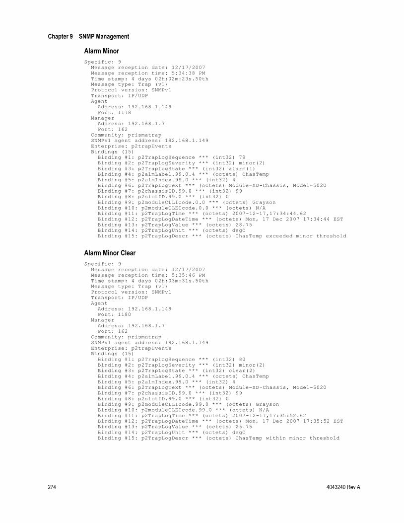
Chapter 9 SNMP Management
274 4043240 Rev A
Alarm Minor
Specific: 9 Message reception date: 12/17/2007 Message reception time: 5:34:38 PM Time stamp: 4 days 02h:02m:23s.50th Message type: Trap (v1) Protocol version: SNMPv1 Transport: IP/UDP Agent Address: 192.168.1.149 Port: 1178 Manager Address: 192.168.1.7 Port: 162 Community: prismatrap SNMPv1 agent address: 192.168.1.149 Enterprise: p2trapEvents Bindings (15) Binding #1: p2TrapLogSequence *** (int32) 79 Binding #2: p2TrapLogSeverity *** (int32) minor(2) Binding #3: p2TrapLogState *** (int32) alarm(1) Binding #4: p2almLabel.99.0.4 *** (octets) ChasTemp Binding #5: p2almIndex.99.0 *** (int32) 4 Binding #6: p2TrapLogText *** (octets) Module=XD-Chassis, Model=5020 Binding #7: p2chassisID.99.0 *** (int32) 99 Binding #8: p2slotID.99.0 *** (int32) 0 Binding #9: p2moduleCLLIcode.0.0 *** (octets) Grayson Binding #10: p2moduleCLEIcode.0.0 *** (octets) N/A Binding #11: p2TrapLogTime *** (octets) 2007-12-17,17:34:44.62 Binding #12: p2TrapLogDateTime *** (octets) Mon, 17 Dec 2007 17:34:44 EST Binding #13: p2TrapLogValue *** (octets) 28.75 Binding #14: p2TrapLogUnit *** (octets) degC Binding #15: p2TrapLogDescr *** (octets) ChasTemp exceeded minor threshold
Alarm Minor Clear
Specific: 9 Message reception date: 12/17/2007 Message reception time: 5:35:46 PM Time stamp: 4 days 02h:03m:31s.50th Message type: Trap (v1) Protocol version: SNMPv1 Transport: IP/UDP Agent Address: 192.168.1.149 Port: 1180 Manager Address: 192.168.1.7 Port: 162 Community: prismatrap SNMPv1 agent address: 192.168.1.149 Enterprise: p2trapEvents Bindings (15) Binding #1: p2TrapLogSequence *** (int32) 80 Binding #2: p2TrapLogSeverity *** (int32) minor(2) Binding #3: p2TrapLogState *** (int32) clear(2) Binding #4: p2almLabel.99.0.4 *** (octets) ChasTemp Binding #5: p2almIndex.99.0 *** (int32) 4 Binding #6: p2TrapLogText *** (octets) Module=XD-Chassis, Model=5020 Binding #7: p2chassisID.99.0 *** (int32) 99 Binding #8: p2slotID.99.0 *** (int32) 0 Binding #9: p2moduleCLLIcode.99.0 *** (octets) Grayson Binding #10: p2moduleCLEIcode.99.0 *** (octets) N/A Binding #11: p2TrapLogTime *** (octets) 2007-12-17,17:35:52.62 Binding #12: p2TrapLogDateTime *** (octets) Mon, 17 Dec 2007 17:35:52 EST Binding #13: p2TrapLogValue *** (octets) 25.75 Binding #14: p2TrapLogUnit *** (octets) degC Binding #15: p2TrapLogDescr *** (octets) ChasTemp within minor threshold

Prisma II Traps
4043240 Rev A 275
Enhanced Trap Events
The current system release supports Enhanced traps that alert management to certain events related to user login, changes to system settings, event log memory usage, SNTP failures, and user lockout activity.
All event traps display binding 2 (severity) as warning (3) and binding 3 (state) as event (3).
Binding 4 (label) may be an alarm label, or may include any of the following event types:
Admin Change
Authentication Failed
Download Complete (reserved for future use)
IP Change
Login Threshold
Log (Event Log)
Module Insert
Module Remove
Reboot
SelfTest
SNTP (reserved for future use)
Update Chassis IDs
User Lockout
For example:
Binding #2: p2TrapLogSeverity *** (int32) warning(3) Binding #3: p2TrapLogState *** (int32) event(3) Binding #4: p2TrapLogLabel *** (octets) AdminChange
This section describes the events that cause each of these traps to be sent and gives examples of each trap where appropriate.

Chapter 9 SNMP Management
276 4043240 Rev A
AdminChange
An AdminChange trap is sent when an Admin user performs one of the following actions.
Add a user
Change a password
Change access level
Enable or disable the status of a user
Delete a user
Fail to add a user because the list of users is full (16)
Change the inactivity timeout
Change the login thresholds
Change the User Lockout interval setting

Prisma II Traps
4043240 Rev A 277
Admin Change Example - Add New User
Specific: 9 Message reception date: 10/30/2006 Message reception time: 1:46:53.476 PM Time stamp: 2 days 22h:12m:43s.91th Message type: Trap (v1) Protocol version: SNMPv1 Transport: IP/UDP Agent Address: 172.24.25.175 Port: 1055 Manager Address: 172.18.10.23 Port: 162 Community: prismatrap SNMPv1 agent address: 172.24.25.175 Enterprise: p2trapEvents Bindings (15) Binding #1: p2TrapLogSequence *** (int32) 22 Binding #2: p2TrapLogSeverity *** (int32) warning(3) Binding #3: p2TrapLogState *** (int32) event(3) Binding #4: p2TrapLogLabel *** (octets) AdminChange Binding #5: p2icimStatusMsg.0 *** (int32) 0 Binding #6: p2TrapLogText *** (octets) ICIM2 Binding #7: p2chassisID.1.15 *** (int32) 1 Binding #8: p2slotID.1.15 *** (int32) 15 Binding #9: p2moduleCLLIcode.1.15 *** (octets) Engineering Lab Binding #10: p2moduleCLEIcode.1.15 *** (octets) ICIMCLEI75 Binding #11: p2TrapLogTime *** (octets) 2006-10-30,13:46:35.19 Binding #12: p2TrapLogDateTime *** (octets) Mon, 30 Oct 2006 13:46:35 EST Binding #13: p2TrapLogValue *** (octets) N/A Binding #14: p2TrapLogUnit *** (octets) N/A Binding #15: p2TrapLogDescr *** (octets) Add user ReadWrite3
Admin Change Example - Change ICIM Setting (Inactivity Timer)
Specific: 9 Message reception date: 10/30/2006 Message reception time: 1:25:26.078 PM Time stamp: 2 days 21h:51m:16s.53th Message type: Trap (v1) Protocol version: SNMPv1 Transport: IP/UDP Agent Address: 172.24.25.175 Port: 1054 Manager Address: 172.18.10.23 Port: 162 Community: prismatrap SNMPv1 agent address: 172.24.25.175 Enterprise: p2trapEvents Bindings (15) Binding #1: p2TrapLogSequence *** (int32) 21 Binding #2: p2TrapLogSeverity *** (int32) warning(3) Binding #3: p2TrapLogState *** (int32) event(3) Binding #4: p2TrapLogLabel *** (octets) AdminChange Binding #5: p2icimStatusMsg.0 *** (int32) 0 Binding #6: p2TrapLogText *** (octets) ICIM2 Binding #7: p2chassisID.1.15 *** (int32) 1 Binding #8: p2slotID.1.15 *** (int32) 15 Binding #9: p2moduleCLLIcode.1.15 *** (octets) Engineering Lab Binding #10: p2moduleCLEIcode.1.15 *** (octets) ICIMCLEI75 Binding #11: p2TrapLogTime *** (octets) 2006-10-30,13:25:7.77 Binding #12: p2TrapLogDateTime *** (octets) Mon, 30 Oct 2006 13:25:07 EST Binding #13: p2TrapLogValue *** (octets) N/A Binding #14: p2TrapLogUnit *** (octets) N/A Binding #15: p2TrapLogDescr *** (octets) Change inactivity timer setting to: 10 minutes

Chapter 9 SNMP Management
278 4043240 Rev A
Admin Change Example - Change ICIM Setting (Login Threshold)
Specific: 9 Message reception date: 10/30/2006 Message reception time: 1:19:04.310 PM Time stamp: 2 days 21h:44m:54s.78th Message type: Trap (v1) Protocol version: SNMPv1 Transport: IP/UDP Agent Address: 172.24.25.175 Port: 1049 Manager Address: 172.18.10.23 Port: 162 Community: prismatrap SNMPv1 agent address: 172.24.25.175 Enterprise: p2trapEvents Bindings (15) Binding #1: p2TrapLogSequence *** (int32) 16 Binding #2: p2TrapLogSeverity *** (int32) warning(3) Binding #3: p2TrapLogState *** (int32) event(3) Binding #4: p2TrapLogLabel *** (octets) AdminChange Binding #5: p2icimStatusMsg.0 *** (int32) 0 Binding #6: p2TrapLogText *** (octets) ICIM2 Binding #7: p2chassisID.1.15 *** (int32) 1 Binding #8: p2slotID.1.15 *** (int32) 15 Binding #9: p2moduleCLLIcode.1.15 *** (octets) Engineering Lab Binding #10: p2moduleCLEIcode.1.15 *** (octets) ICIMCLEI75 Binding #11: p2TrapLogTime *** (octets) 2006-10-30,13:18:46.0 Binding #12: p2TrapLogDateTime *** (octets) Mon, 30 Oct 2006 13:18:46 EST Binding #13: p2TrapLogValue *** (octets) N/A Binding #14: p2TrapLogUnit *** (octets) N/A Binding #15: p2TrapLogDescr *** (octets) Change login threshold setting to: 5 minutes
Admin Change Example - Change User Password
Specific: 9 Message reception date: 10/30/2006 Message reception time: 1:48:37.618 PM Time stamp: 2 days 22h:14m:28s.06th Message type: Trap (v1) Protocol version: SNMPv1 Transport: IP/UDP Agent Address: 172.24.25.175 Port: 1056 Manager Address: 172.18.10.23 Port: 162 Community: prismatrap SNMPv1 agent address: 172.24.25.175 Enterprise: p2trapEvents Bindings (15) Binding #1: p2TrapLogSequence *** (int32) 23 Binding #2: p2TrapLogSeverity *** (int32) warning(3) Binding #3: p2TrapLogState *** (int32) event(3) Binding #4: p2TrapLogLabel *** (octets) AdminChange Binding #5: p2icimStatusMsg.0 *** (int32) 0 Binding #6: p2TrapLogText *** (octets) ICIM2 Binding #7: p2chassisID.1.15 *** (int32) 1 Binding #8: p2slotID.1.15 *** (int32) 15 Binding #9: p2moduleCLLIcode.1.15 *** (octets) Engineering Lab Binding #10: p2moduleCLEIcode.1.15 *** (octets) ICIMCLEI75 Binding #11: p2TrapLogTime *** (octets) 2006-10-30,13:48:19.34 Binding #12: p2TrapLogDateTime *** (octets) Mon, 30 Oct 2006 13:48:19 EST Binding #13: p2TrapLogValue *** (octets) N/A Binding #14: p2TrapLogUnit *** (octets) N/A Binding #15: p2TrapLogDescr *** (octets) Changed user password for ReadWrite3

Prisma II Traps
4043240 Rev A 279
Admin Change Example - Delete User
Specific: 9 Message reception date: 10/30/2006 Message reception time: 1:50:06.243 PM Time stamp: 2 days 22h:15m:56s.68th Message type: Trap (v1) Protocol version: SNMPv1 Transport: IP/UDP Agent Address: 172.24.25.175 Port: 1057 Manager Address: 172.18.10.23 Port: 162 Community: prismatrap SNMPv1 agent address: 172.24.25.175 Enterprise: p2trapEvents Bindings (15) Binding #1: p2TrapLogSequence *** (int32) 24 Binding #2: p2TrapLogSeverity *** (int32) warning(3) Binding #3: p2TrapLogState *** (int32) event(3) Binding #4: p2TrapLogLabel *** (octets) AdminChange Binding #5: p2icimStatusMsg.0 *** (int32) 0 Binding #6: p2TrapLogText *** (octets) ICIM2 Binding #7: p2chassisID.1.15 *** (int32) 1 Binding #8: p2slotID.1.15 *** (int32) 15 Binding #9: p2moduleCLLIcode.1.15 *** (octets) Engineering Lab Binding #10: p2moduleCLEIcode.1.15 *** (octets) ICIMCLEI75 Binding #11: p2TrapLogTime *** (octets) 2006-10-30,13:49:47.97 Binding #12: p2TrapLogDateTime *** (octets) Mon, 30 Oct 2006 13:49:47 EST Binding #13: p2TrapLogValue *** (octets) N/A Binding #14: p2TrapLogUnit *** (octets) N/A Binding #15: p2TrapLogDescr *** (octets) Delete user ReadWrite3
AuthentictnFailed
An AuthentictnFailed trap is sent when a user login (authentication) fails due to one of the following causes:
The user ID is disabled.
The password is not correct.
The user ID is not correct or is not found.
Too many users are logged into the ICIM at this time.
The list of valid users could not be retrieved from the EEPROM.

Chapter 9 SNMP Management
280 4043240 Rev A
Authentication Failed - Password incorrect
Specific: 9 Message reception date: 10/30/2006 Message reception time: 1:15:21.261 PM Time stamp: 2 days 21h:41m:11s.73th Message type: Trap (v1) Protocol version: SNMPv1 Transport: IP/UDP Agent Address: 172.24.25.175 Port: 1048 Manager Address: 172.18.10.23 Port: 162 Community: prismatrap SNMPv1 agent address: 172.24.25.175 Enterprise: p2trapEvents Bindings (15) Binding #1: p2TrapLogSequence *** (int32) 15 Binding #2: p2TrapLogSeverity *** (int32) warning(3) Binding #3: p2TrapLogState *** (int32) event(3) Binding #4: p2TrapLogLabel *** (octets) AuthentictnFailed Binding #5: p2icimStatusMsg.0 *** (int32) 0 Binding #6: p2TrapLogText *** (octets) ICIM2 Binding #7: p2chassisID.1.15 *** (int32) 1 Binding #8: p2slotID.1.15 *** (int32) 15 Binding #9: p2moduleCLLIcode.1.15 *** (octets) Engineering Lab Binding #10: p2moduleCLEIcode.1.15 *** (octets) ICIMCLEI75 Binding #11: p2TrapLogTime *** (octets) 2006-10-30,13:15:2.94 Binding #12: p2TrapLogDateTime *** (octets) Mon, 30 Oct 2006 13:15:02 EST Binding #13: p2TrapLogValue *** (octets) N/A Binding #14: p2TrapLogUnit *** (octets) N/A Binding #15: p2TrapLogDescr *** (octets) Password failed: Administrat0r
Authentication Failed - User ID Disabled
Specific: 9 Message reception date: 10/30/2006 Message reception time: 4:31:48.399 PM Time stamp: 0 days 00h:06m:26s.51th Message type: Trap (v1) Protocol version: SNMPv1 Transport: IP/UDP Agent Address: 172.24.28.151 Port: 1047 Manager Address: 172.18.10.23 Port: 162 Community: prismatrap SNMPv1 agent address: 172.24.28.151 Enterprise: p2trapEvents Bindings (15) Binding #1: p2TrapLogSequence *** (int32) 24 Binding #2: p2TrapLogSeverity *** (int32) warning(3) Binding #3: p2TrapLogState *** (int32) event(3) Binding #4: p2TrapLogLabel *** (octets) AuthentictnFailed Binding #5: p2icimStatusMsg.0 *** (int32) 0 Binding #6: p2TrapLogText *** (octets) ICIM2 Binding #7: p2chassisID.3.15 *** (int32) 3 Binding #8: p2slotID.3.15 *** (int32) 15 Binding #9: p2moduleCLLIcode.3.15 *** (octets) icimCLLIcode7 Binding #10: p2moduleCLEIcode.3.15 *** (octets) (zero-length) Binding #11: p2TrapLogTime *** (octets) 2006-10-30,16:33:14.89 Binding #12: p2TrapLogDateTime *** (octets) Mon, 30 Oct 2006 16:33:14 EST Binding #13: p2TrapLogValue *** (octets) N/A Binding #14: p2TrapLogUnit *** (octets) N/A Binding #15: p2TrapLogDescr *** (octets) Try to login to a disabled account: bogusUser2

Prisma II Traps
4043240 Rev A 281
Download Complete
This trap is reserved for future use.
IP Change
An IPChange trap is sent as notification that the IP address of the ICIM has been changed.
IP Change Example - ICIM IP Change
Specific: 9 Message reception date: 8/25/2006 Message reception time: 10:03:30.896 AM Time stamp: 0 days 00h:15m:19s.00th Message type: Trap (v1) Protocol version: SNMPv1 Transport: IP/UDP Agent Address: 172.2.5.168 Port: 1030 Manager Address: 172.24.3.151 Port: 162 Community: prismatrap SNMPv1 agent address: 172.2.5.168 Enterprise: p2trapEvents Bindings (15) Binding #1: p2TrapLogSequence *** (int32) 7 Binding #2: p2TrapLogSeverity *** (int32) warning(3) Binding #3: p2TrapLogState *** (int32) event(3) Binding #4: p2TrapLogLabel *** (octets) IPchange Binding #5: p2icimIPAddr *** (int32) 0 Binding #6: p2TrapLogText *** (octets) ICIM IP address changed -- 172.24.28.151. Binding #7: p2icimChassisID *** (int32) 0 Binding #8: p2icimSlotID *** (int32) 15 Binding #9: p2icimCLLIcode *** (octets) SCIATL01 Binding #10: p2icimCLEIcode *** (octets) VLLUAA4DAA Binding #11: p2TrapLogTime *** (octets) 2006-8-25,10:5:8.42 Binding #12: p2TrapLogDateTime *** (octets) Fri, 25 Aug 2006 10:05:08 EDT Binding #13: p2TrapLogValue *** (octets) N/A Binding #14: p2TrapLogUnit *** (octets) N/A Binding #15: p2TrapLogDescr *** (octets) ICIM IP Address has been changed

Chapter 9 SNMP Management
282 4043240 Rev A
LoginThreshold
The LoginThreshold trap is sent when a user reaches the number of failed login attempts via the CLI or Web Interface as allowed by the login threshold.
Login Threshold Example - Too Many Failed Login Attempts
Specific: 9 Message reception date: 10/30/2006 Message reception time: 1:19:29.216 PM Time stamp: 2 days 21h:45m:19s.70th Message type: Trap (v1) Protocol version: SNMPv1 Transport: IP/UDP Agent Address: 172.24.25.175 Port: 1052 Manager Address: 172.18.10.23 Port: 162 Community: prismatrap SNMPv1 agent address: 172.24.25.175 Enterprise: p2trapEvents Bindings (15) Binding #1: p2TrapLogSequence *** (int32) 19 Binding #2: p2TrapLogSeverity *** (int32) warning(3) Binding #3: p2TrapLogState *** (int32) event(3) Binding #4: p2TrapLogLabel *** (octets) LoginThreshold Binding #5: p2icimStatusMsg.0 *** (int32) 0 Binding #6: p2TrapLogText *** (octets) ICIM2 Binding #7: p2chassisID.1.15 *** (int32) 1 Binding #8: p2slotID.1.15 *** (int32) 15 Binding #9: p2moduleCLLIcode.1.15 *** (octets) Engineering Lab Binding #10: p2moduleCLEIcode.1.15 *** (octets) ICIMCLEI75 Binding #11: p2TrapLogTime *** (octets) 2006-10-30,13:19:10.91 Binding #12: p2TrapLogDateTime *** (octets) Mon, 30 Oct 2006 13:19:10 EST Binding #13: p2TrapLogValue *** (octets) N/A Binding #14: p2TrapLogUnit *** (octets) N/A Binding #15: p2TrapLogDescr *** (octets) Maximum failed session login attempts reached
Log Memory Traps
The event log traps LogMemHalfFull or LogMemoryFull are sent when the event log is nearing capacity. Traps are sent at each of the following intervals.
80% full
85% full
90% full
95% full
100% full
When all 5,000 entries in the event log table are filled, the LogMemoryFull trap is sent. New entries then replace the oldest entries as the information wraps. No additional LogMemoryFull traps are sent.

Prisma II Traps
4043240 Rev A 283
LogMemHalfFull Example
Specific: 9 Message reception date: 9/13/2006 Message reception time: 2:27:25.066 PM Time stamp: 0 days 00h:11m:20s.13th Message type: Trap (v1) Protocol version: SNMPv1 Transport: IP/UDP Agent Address: 172.24.28.193 Port: 1035 Manager Address: 172.18.9.66 Port: 162 Community: prismatrap SNMPv1 agent address: 172.24.28.193 Enterprise: p2trapEvents Bindings (15) Binding #1: p2TrapLogSequence *** (int32) 12 Binding #2: p2TrapLogSeverity *** (int32) warning(3) Binding #3: p2TrapLogState *** (int32) event(3) Binding #4: p2TrapLogLabel *** (octets) LogMemHalfFull Binding #5: p2icimStatusMsg.0 *** (int32) 0 Binding #6: p2TrapLogText *** (octets) ICIM2 Binding #7: p2chassisID.2.15 *** (int32) 2 Binding #8: p2slotID.2.15 *** (int32) 15 Binding #9: p2moduleCLLIcode.2.15 *** (octets) 1.2.243 Binding #10: p2moduleCLEIcode.2.15 *** (octets) (zero-length) Binding #11: p2TrapLogTime *** (octets) 2006-9-13,1:51:39.42 Binding #12: p2TrapLogDateTime *** (octets) Wed, 13 Sep 2006 01:51:39 EST Binding #13: p2TrapLogValue *** (octets) N/A Binding #14: p2TrapLogUnit *** (octets) N/A Binding #15: p2TrapLogDescr *** (octets) Log memory is %80 full
LogMemoryFull Example
Specific: 9 Message reception date: 9/13/2006 Message reception time: 2:44:27.081 PM Time stamp: 0 days 00h:28m:22s.13th Message type: Trap (v1) Protocol version: SNMPv1 Transport: IP/UDP Agent Address: 172.24.28.193 Port: 1039 Manager Address: 172.18.9.66 Port: 162 Community: prismatrap SNMPv1 agent address: 172.24.28.193 Enterprise: p2trapEvents Bindings (15) Binding #1: p2TrapLogSequence *** (int32) 16 Binding #2: p2TrapLogSeverity *** (int32) warning(3) Binding #3: p2TrapLogState *** (int32) event(3) Binding #4: p2TrapLogLabel *** (octets) LogMemoryFull Binding #5: p2icimStatusMsg.0 *** (int32) 0 Binding #6: p2TrapLogText *** (octets) ICIM2 Binding #7: p2chassisID.2.15 *** (int32) 2 Binding #8: p2slotID.2.15 *** (int32) 15 Binding #9: p2moduleCLLIcode.2.15 *** (octets) 1.2.243 Binding #10: p2moduleCLEIcode.2.15 *** (octets) (zero-length) Binding #11: p2TrapLogTime *** (octets) 2006-9-13,2:8:41.45 Binding #12: p2TrapLogDateTime *** (octets) Wed, 13 Sep 2006 02:08:41 EST Binding #13: p2TrapLogValue *** (octets) N/A Binding #14: p2TrapLogUnit *** (octets) N/A Binding #15: p2TrapLogDescr *** (octets) Log memory is %100 full

Chapter 9 SNMP Management
284 4043240 Rev A
LogWriteError
An Event trap is sent when an attempt to write to the event log fails. This serves as a backup to alert the management system to a problem writing to the event log.
LogWriteError Example
Specific: 9 Message reception date: 9/13/2006 Message reception time: 2:44:27.081 PM Time stamp: 0 days 00h:28m:22s.13th Message type: Trap (v1) Protocol version: SNMPv1 Transport: IP/UDP Agent Address: 172.24.28.193 Port: 1039 Manager Address: 172.18.9.66 Port: 162 Community: prismatrap SNMPv1 agent address: 172.24.28.193 Enterprise: p2trapEvents Bindings (15) Binding #1: p2TrapLogSequence *** (int32) 16 Binding #2: p2TrapLogSeverity *** (int32) warning(3) Binding #3: p2TrapLogState *** (int32) event(3) Binding #4: p2TrapLogLabel *** (octets) LogWriteError Binding #5: p2icimStatusMsg.0 *** (int32) 0 Binding #6: p2TrapLogText *** (octets) ICIM2 Binding #7: p2chassisID.2.15 *** (int32) 2 Binding #8: p2slotID.2.15 *** (int32) 15 Binding #9: p2moduleCLLIcode.2.15 *** (octets) 1.2.243 Binding #10: p2moduleCLEIcode.2.15 *** (octets) (zero-length) Binding #11: p2TrapLogTime *** (octets) 2006-9-13,2:8:41.45 Binding #12: p2TrapLogDateTime *** (octets) Wed, 13 Sep 2006 02:08:41 EST Binding #13: p2TrapLogValue *** (octets) N/A Binding #14: p2TrapLogUnit *** (octets) N/A Binding #15: p2TrapLogDescr *** (octets) Log error, can't log message: Password failed: UserName14

Prisma II Traps
4043240 Rev A 285
Module Insert
A ModuleInsert trap is sent when an application module is inserted into a chassis in the ICIM domain.
Module Insert Example
Specific: 9 Message reception date: 8/22/2006 Message reception time: 4:54:36.478 PM Time stamp: 0 days 01h:09m:16s.00th Message type: Trap (v1) Protocol version: SNMPv1 Transport: IP/UDP Agent Address: 172.2.5.168 Port: 1034 Manager Address: 172.24.3.151 Port: 162 Community: prismatrap SNMPv1 agent address: 172.2.5.168 Enterprise: p2trapEvents Bindings (15) Binding #1: p2TrapLogSequence *** (int32) 11 Binding #2: p2TrapLogSeverity *** (int32) warning(3) Binding #3: p2TrapLogState *** (int32) event(3) Binding #4: p2TrapLogLabel *** (octets) ModuleInsert Binding #5: p2InsertModuleEntry *** (int32) 0 Binding #6: p2TrapLogText *** (octets) Not available Binding #7: p2chassisID.0.11 *** (int32) 0 Binding #8: p2slotID.0.11 *** (int32) 11 Binding #9: p2moduleCLLIcode.0.11 *** (octets) SCIATL01 Binding #10: p2moduleCLEIcode.0.11 *** (octets) CLEIcode Binding #11: p2TrapLogTime *** (octets) 2006-8-22,16:54:36.45 Binding #12: p2TrapLogDateTime *** (octets) Tue, 22 Aug 2006 16:54:36 EST Binding #13: p2TrapLogValue *** (octets) N/A Binding #14: p2TrapLogUnit *** (octets) N/A Binding #15: p2TrapLogDescr *** (octets) A module has been inserted into a chassis

Chapter 9 SNMP Management
286 4043240 Rev A
ModuleRemove
A ModuleRemove trap is sent when an application module is removed from a chassis in the ICIM domain.
Module Remove Example
Specific: 9 Message reception date: 8/22/2006 Message reception time: 4:34:08.853 PM Time stamp: 0 days 00h:48m:48s.00th Message type: Trap (v1) Protocol version: SNMPv1 Transport: IP/UDP Agent Address: 172.2.5.168 Port: 1033 Manager Address: 172.24.3.151 Port: 162 Community: prismatrap SNMPv1 agent address: 172.2.5.168 Enterprise: p2trapEvents Bindings (15) Binding #1: p2TrapLogSequence *** (int32) 10 Binding #2: p2TrapLogSeverity *** (int32) warning(3) Binding #3: p2TrapLogState *** (int32) event(3) Binding #4: p2TrapLogLabel *** (octets) ModuleRemove Binding #5: p2RemoveModuleEntry *** (int32) 0 Binding #6: p2TrapLogText *** (octets) Not available Binding #7: p2chassisID.0.11 *** (int32) 0 Binding #8: p2slotID.0.11 *** (int32) 11 Binding #9: p2moduleCLLIcode.0.11 *** (octets) SCIATL01 Binding #10: p2moduleCLEIcode.0.11 *** (octets) CLEIcode Binding #11: p2TrapLogTime *** (octets) 2006-8-22,16:34:8.84 Binding #12: p2TrapLogDateTime *** (octets) Tue, 22 Aug 2006 16:34:08 EST Binding #13: p2TrapLogValue *** (octets) N/A Binding #14: p2TrapLogUnit *** (octets) N/A Binding #15: p2TrapLogDescr *** (octets) A module has been removed from a chassis

Prisma II Traps
4043240 Rev A 287
Reboot
The Reboot trap is sent when an ICIM or application module has been commanded to reboot, either individually or as a result of a broadcast reboot command.
Reboot Example - Broadcast Reboot Command
Specific: 9 Message reception date: 8/28/2006 Message reception time: 2:20:20.014 PM Time stamp: 0 days 00h:03m:34s.00th Message type: Trap (v1) Protocol version: SNMPv1 Transport: IP/UDP Agent Address: 172.2.5.168 Port: 1032 Manager Address: 172.24.3.151 Port: 162 Community: prismatrap SNMPv1 agent address: 172.2.5.168 Enterprise: p2trapEvents Bindings (15) Binding #1: p2TrapLogSequence *** (int32) 9 Binding #2: p2TrapLogSeverity *** (int32) warning(3) Binding #3: p2TrapLogState *** (int32) event(3) Binding #4: p2TrapLogLabel *** (octets) RebootCommand Binding #5: p2icimStatusMsg *** (int32) 0 Binding #6: p2TrapLogText *** (octets) Broadcast Binding #7: p2chassisID.99.99 *** (int32) 99 Binding #8: p2slotID.99.99 *** (int32) 99 Binding #9: p2moduleCLLIcode.99.99 *** (octets) N/A Binding #10: p2moduleCLEIcode.99.99 *** (octets) N/A Binding #11: p2TrapLogTime *** (octets) 2006-8-28,14:20:20.43 Binding #12: p2TrapLogDateTime *** (octets) Mon, 28 Aug 2006 14:20:20 EST Binding #13: p2TrapLogValue *** (octets) N/A Binding #14: p2TrapLogUnit *** (octets) N/A Binding #15: p2TrapLogDescr *** (octets) An ICIM/module has been commanded to reboot (CH 99 SL 99 indicates a broadcast reboot)

Chapter 9 SNMP Management
288 4043240 Rev A
Reboot Example - Reboot ICIM Command
Specific: 9 Message reception date: 8/22/2006 Message reception time: 3:44:20.455 PM Time stamp: 0 days 00h:10m:17s.00th Message type: Trap (v1) Protocol version: SNMPv1 Transport: IP/UDP Agent Address: 172.2.5.168 Port: 1034 Manager Address: 172.24.3.151 Port: 162 Community: prismatrap SNMPv1 agent address: 172.2.5.168 Enterprise: p2trapEvents Bindings (15) Binding #1: p2TrapLogSequence *** (int32) 11 Binding #2: p2TrapLogSeverity *** (int32) warning(3) Binding #3: p2TrapLogState *** (int32) event(3) Binding #4: p2TrapLogLabel *** (octets) RebootCommand Binding #5: p2icimStatusMsg *** (int32) 0 Binding #6: p2TrapLogText *** (octets) Broadcast Binding #7: p2chassisID.99.99 *** (int32) 99 Binding #8: p2slotID.99.99 *** (int32) 99 Binding #9: p2moduleCLLIcode.99.99 *** (octets) SCIATL01 Binding #10: p2moduleCLEIcode.99.99 *** (octets) CLEIcode Binding #11: p2TrapLogTime *** (octets) 2006-8-22,15:44:21.0 Binding #12: p2TrapLogDateTime *** (octets) Tue, 22 Aug 2006 15:44:21 EST Binding #13: p2TrapLogValue *** (octets) N/A Binding #14: p2TrapLogUnit *** (octets) N/A Binding #15: p2TrapLogDescr *** (octets) An ICIM/module has been commanded to reboot (CH 99 SL 99 indicates a broadcast reboot)

Prisma II Traps
4043240 Rev A 289
SelfTest
A SelfTest trap is sent when either the ICIM or application module fails its power-on self test.
SelfTest Example - ICIM Failure
Specific: 9 Message reception date: 8/25/2006 Message reception time: 9:43:26.623 AM Time stamp: 0 days 00h:00m:57s.00th Message type: Trap (v1) Protocol version: SNMPv1 Transport: IP/UDP Agent Address: 172.2.5.168 Port: 1024 Manager Address: 172.24.3.151 Port: 162 Community: prismatrap SNMPv1 agent address: 172.2.5.168 Enterprise: p2trapEvents Bindings (15) Binding #1: p2TrapLogSequence *** (int32) 1 Binding #2: p2TrapLogSeverity *** (int32) warning(3) Binding #3: p2TrapLogState *** (int32) event(3) Binding #4: p2TrapLogLabel *** (octets) SelfTest Binding #5: p2icimSelfTest *** (int32) 0 Binding #6: p2TrapLogText *** (octets) SelfTest Failed - Error Code 16777232 Binding #7: p2icimChassisID *** (int32) 0 Binding #8: p2icimSlotID *** (int32) 15 Binding #9: p2icimCLLIcode *** (octets) SCIATL01 Binding #10: p2icimCLEIcode *** (octets) VLLUAA4DAA Binding #11: p2TrapLogTime *** (octets) 2006-8-25,9:45:1.76 Binding #12: p2TrapLogDateTime *** (octets) Fri, 25 Aug 2006 09:45:01 EDT Binding #13: p2TrapLogValue *** (octets) N/A Binding #14: p2TrapLogUnit *** (octets) N/A Binding #15: p2TrapLogDescr *** (octets) An ICIM/module has failed its power-on self test

Chapter 9 SNMP Management
290 4043240 Rev A
SelfTest Example - Module Failure
Specific: 9 Message reception date: 8/25/2006 Message reception time: 9:49:50.657 AM Time stamp: 0 days 00h:01m:39s.00th Message type: Trap (v1) Protocol version: SNMPv1 Transport: IP/UDP Agent Address: 172.2.5.168 Port: 1024 Manager Address: 172.24.3.151 Port: 162 Community: prismatrap SNMPv1 agent address: 172.2.5.168 Enterprise: p2trapEvents Bindings (15) Binding #1: p2TrapLogSequence *** (int32) 1 Binding #2: p2TrapLogSeverity *** (int32) warning(3) Binding #3: p2TrapLogState *** (int32) event(3) Binding #4: p2TrapLogLabel *** (octets) SelfTest Binding #5: p2moduleSelfTest.0.0 *** (int32) 0 Binding #6: p2TrapLogText *** (octets) SelfTest Failed - Error Code 33558528 Binding #7: p2chassisID.0.0 *** (int32) 0 Binding #8: p2slotID.0.0 *** (int32) 0 Binding #9: p2moduleCLLIcode.0.0 *** (octets) SCIATL01 Binding #10: p2moduleCLEIcode.0.0 *** (octets)CLEIcode Binding #11: p2TrapLogTime *** (octets) 2006-8-25,9:51:28.17 Binding #12: p2TrapLogDateTime *** (octets) Fri, 25 Aug 2006 09:51:28 EDT Binding #13: p2TrapLogValue *** (octets) N/A Binding #14: p2TrapLogUnit *** (octets) N/A Binding #15: p2TrapLogDescr *** (octets) An ICIM/module has failed its power-on self test
SNTP
This trap is reserved for future use.

Prisma II Traps
4043240 Rev A 291
UpdateChassisID
The UpdateChassisID trap is sent to indicate that the ICIM is rediscovering the domain as a result of one of the following actions.
The p2icimUpdateChassisID is set to 1 via SNMP.
The CLI command set updateid 1 is issued from the ICIM> command prompt.
UpdateChassisID Example
Specific: 9 Message reception date: 10/30/2006 Message reception time: 12:39:26.263 PM Time stamp: 0 days 00h:04m:32s.51th Message type: Trap (v1) Protocol version: SNMPv1 Transport: IP/UDP Agent Address: 172.24.28.151 Port: 1037 Manager Address: 172.18.10.23 Port: 162 Community: prismatrap SNMPv1 agent address: 172.24.28.151 Enterprise: p2trapEvents Bindings (15) Binding #1: p2TrapLogSequence *** (int32) 14 Binding #2: p2TrapLogSeverity *** (int32) warning(3) Binding #3: p2TrapLogState *** (int32) event(3) Binding #4: p2TrapLogLabel *** (octets) UpdateChassisIDs Binding #5: p2icimUpdateChassisIDs *** (int32) 0 Binding #6: p2TrapLogText *** (octets) ICIM2 Binding #7: p2chassisID.4.15 *** (int32) 4 Binding #8: p2slotID.4.15 *** (int32) 15 Binding #9: p2moduleCLLIcode.4.15 *** (octets) icimCLLIcode7 Binding #10: p2moduleCLEIcode.4.15 *** (octets) (zero-length) Binding #11: p2TrapLogTime *** (octets) 2006-10-30,12:40:9.94 Binding #12: p2TrapLogDateTime *** (octets) Mon, 30 Oct 2006 12:40:09 EST Binding #13: p2TrapLogValue *** (octets) N/A Binding #14: p2TrapLogUnit *** (octets) N/A Binding #15: p2TrapLogDescr *** (octets) A user requested update for all chassis IDs has occurred

Chapter 9 SNMP Management
292 4043240 Rev A
UserLockout
The UserLockout trap is sent whenever a user is locked out as a result of reaching the failed login attempts threshold. The UserLockout event may result in the following message:
User <user_name> has reached maximum failed login attempts and been locked out.
UserLockout Example
Specific: 9 Message reception date: 3/15/2007 Message reception time: 2:15:02.352 PM Time stamp: 0 days 00h:21m:11s.61th Message type: Trap (v1) Protocol version: SNMPv1 Transport: IP/UDP Agent Address: 190.2.0.110 Port: 1056 Manager Address: 190.2.0.108 Port: 162 Community: prismatrap SNMPv1 agent address: 190.2.0.114 Enterprise: p2trapEvents Bindings (15) Binding #1: p2TrapLogSequence *** (int32) 32 Binding #2: p2TrapLogSeverity *** (int32) warning(3) Binding #3: p2TrapLogState *** (int32) event(3) Binding #4: p2TrapLogLabel *** (octets) UserLockout Binding #5: p2icimStatusMsg *** (int32) 0 Binding #6: p2TrapLogText *** (octets) ICIM2 Binding #7: p2chassisID.3.15 *** (int32) 3 Binding #8: p2slotID.3.15 *** (int32) 15 Binding #9: p2moduleCLLIcode.3.15 *** (octets) ICIMCLLI Binding #10: p2moduleCLEIcode.3.15 *** (octets) VLLUAA4DAA Binding #11: p2TrapLogTime *** (octets) 2007-3-15,14:15:1.84 Binding #12: p2TrapLogDateTime *** (octets) Thu, 15 Mar 2007 14:15:01 EDT Binding #13: p2TrapLogValue *** (octets) N/A Binding #14: p2TrapLogUnit *** (octets) N/A Binding #15: p2TrapLogDescr *** (octets) User ferret3 has reached maximum failed login attempts and been locked out.

Alarm Threshold Modification
4043240 Rev A 293
Alarm Threshold Modification The meaning of an alarm value is relative to the type of alarm. For example, a p2almValue of 0 (zero) indicates OK for a Boolean alarm type (p2almType = 5 or 6), but signals a Major Low alarm for a Non-Boolean alarm type (p2almType = 1, 2, 3, 4, 7 or 8). For more information, see Module Alarm Table (on page 235).
The following example illustrates how an alarm threshold may be set, and the subsequent behavior that results from violating the alarm threshold. This behavior includes a module going into an alarm state and a trap being sent.
1 First, observe that the actual value of the +24 V rail in the power supply installed in chassis 20 slot 3 is 24.5577 V, as found in the p2moduleMonitorTable shown below.
p2ChassisID p2SlotID Index Label Value Type Type StateNames
20 3 1 Ps1Inst 0 Inst F N/A20 3 2 Ps1+24V 0 V F N/A20 3 3 Ps1+5VDC 0 V F N/A20 3 4 Ps1-5VDC 0 V F N/A20 3 5 Ps1Temp 0 degC F N/A20 3 6 Ps3Inst 1 Inst F N/A20 3 7 Ps3+24V 24.5577 V F N/A20 3 8 Ps3+5VDC 5.38486 V F N/A20 3 9 Ps3-5VDC -5.39988 V F N/A20 3 10 Ps3Temp 30.4215 degC F N/A20 3 11 Chas+24V 24.2717 V F N/A20 3 12 Chas+5V 5.09947 V F N/A20 3 13 Chas-5V -5.10698 V F N/A20 3 14 ChasTemp 28.2014 degC F N/A20 3 15 FansOn 1 On F N/A
2 Next, moving to the Module Alarm table, we change the minor low limit from 18.4 (below) to 24.9.
p2ChassisID p2SlotID Index Label Value Type Nominal Hysteresis MajorLowLimit MinorLowLimit MinorHighLimit
0 3 1 FansOk 0 (ok) 5 1 N/A N/A N/A N/A1 3 2 ChasTemp 2 (ok) 2 25 1 -40 -35 602 3 3 Ps1PwrIn 1 (fault) 5 1 N/A N/A N/A N/A3 3 4 Ps1+24 1 (minor low) 2 24.7 0.1 18 24.9 25.94 3 5 Ps1+5VDC 2 (ok) 2 5.4 0.1 3.6 3.7 5.95 3 6 Ps1-5VDC 2 (ok) 2 -5.4 0.1 -5.6 -5.5 -4.66 3 7 Ps3PwrIn 0 (ok) 5 1 N/A N/A N/A N/A7 3 8 Ps3+24V 2 (ok) 2 24.7 0.1 18 18.4 25.98 3 9 Ps3+5VDC 2 (ok) 2 5.4 0.1 3.6 3.7 5.99 3 10 Ps3-5VDC 2 (ok) 2 -5.4 0.1 -5.6 -5.5 -4.6
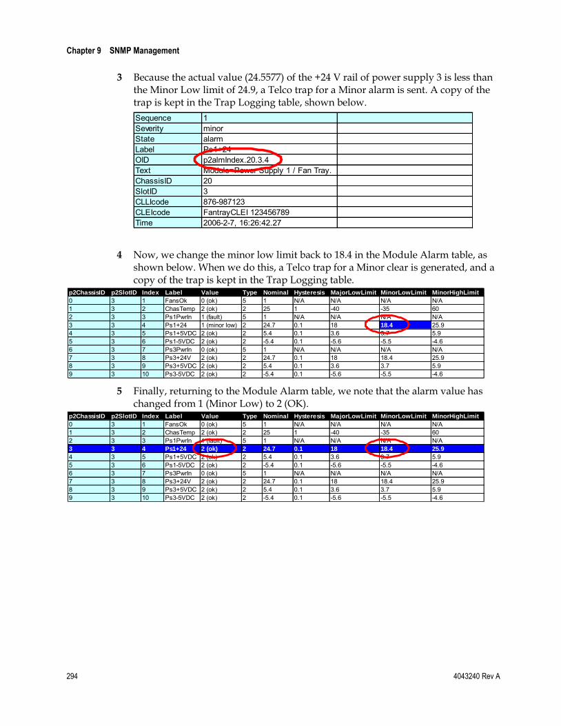
Chapter 9 SNMP Management
294 4043240 Rev A
3 Because the actual value (24.5577) of the +24 V rail of power supply 3 is less than the Minor Low limit of 24.9, a Telco trap for a Minor alarm is sent. A copy of the trap is kept in the Trap Logging table, shown below.
Sequence 1Severity minorState alarmLabel Ps1+24OID p2almIndex.20.3.4Text Module=Power Supply 1 / Fan Tray.ChassisID 20SlotID 3CLLIcode 876-987123CLEIcode FantrayCLEI 123456789Time 2006-2-7, 16:26:42.27
4 Now, we change the minor low limit back to 18.4 in the Module Alarm table, as shown below. When we do this, a Telco trap for a Minor clear is generated, and a copy of the trap is kept in the Trap Logging table.
p2ChassisID p2SlotID Index Label Value Type Nominal Hysteresis MajorLowLimit MinorLowLimit MinorHighLimit
0 3 1 FansOk 0 (ok) 5 1 N/A N/A N/A N/A1 3 2 ChasTemp 2 (ok) 2 25 1 -40 -35 602 3 3 Ps1PwrIn 1 (fault) 5 1 N/A N/A N/A N/A3 3 4 Ps1+24 1 (minor low) 2 24.7 0.1 18 18.4 25.94 3 5 Ps1+5VDC 2 (ok) 2 5.4 0.1 3.6 3.7 5.95 3 6 Ps1-5VDC 2 (ok) 2 -5.4 0.1 -5.6 -5.5 -4.66 3 7 Ps3PwrIn 0 (ok) 5 1 N/A N/A N/A N/A7 3 8 Ps3+24V 2 (ok) 2 24.7 0.1 18 18.4 25.98 3 9 Ps3+5VDC 2 (ok) 2 5.4 0.1 3.6 3.7 5.99 3 10 Ps3-5VDC 2 (ok) 2 -5.4 0.1 -5.6 -5.5 -4.6
5 Finally, returning to the Module Alarm table, we note that the alarm value has changed from 1 (Minor Low) to 2 (OK).
p2ChassisID p2SlotID Index Label Value Type Nominal Hysteresis MajorLowLimit MinorLowLimit MinorHighLimit
0 3 1 FansOk 0 (ok) 5 1 N/A N/A N/A N/A1 3 2 ChasTemp 2 (ok) 2 25 1 -40 -35 602 3 3 Ps1PwrIn 1 (fault) 5 1 N/A N/A N/A N/A3 3 4 Ps1+24 2 (ok) 2 24.7 0.1 18 18.4 25.9
4 3 5 Ps1+5VDC 2 (ok) 2 5.4 0.1 3.6 3.7 5.95 3 6 Ps1-5VDC 2 (ok) 2 -5.4 0.1 -5.6 -5.5 -4.66 3 7 Ps3PwrIn 0 (ok) 5 1 N/A N/A N/A N/A7 3 8 Ps3+24V 2 (ok) 2 24.7 0.1 18 18.4 25.98 3 9 Ps3+5VDC 2 (ok) 2 5.4 0.1 3.6 3.7 5.99 3 10 Ps3-5VDC 2 (ok) 2 -5.4 0.1 -5.6 -5.5 -4.6

System Behavior
4043240 Rev A 295
System Behavior
ICIM as Proxy for Module Information
The user gains access to information about modules in the ICIM domain through the ICIM via SNMP and the MIBs. A virtual database in the ICIM keeps track of data supplied by each module. The ICIM periodically refreshes this database to ensure that the information it provides is up-to-date.
In this way, all module information obtained via SNMP is proxied through the ICIM. Because the modules never interface directly with SNMP, this proxy behavior differs from that of SNMP Proxy Agents, and the two methods should not be confused with each other.
Delay in the Discovery Process
Depending on when an event occurs in relation to the ICIM polling cycle, a user may notice delays in the discovery process.
Such delays may be experienced when inserting or removing a module. For example, if the ICIM has just polled a module in chassis 02 slot 06, and the module is removed, it may be several seconds before the ICIM realizes that chassis 02 slot 06 is empty. Once the empty slot is detected, and if trap destination is configured, a trap indicating module removal will be sent.
Depending on the number of modules managed by an ICIM and the timing of the polling cycle, it may be possible to remove and re-insert a module from chassis 02 slot 06, for example, without the ICIM even detecting that it was missing.
Module Removal and Enhanced Traps
If a module is removed, an Enhanced trap is sent. No other traps indicating alarms or clearings are sent for that module. Once again, because of the delay in the discovery process, it may be possible to remove and reinsert a module without traps being sent.

Chapter 9 SNMP Management
296 4043240 Rev A
Frequently Asked Questions
How do I configure trap destination?
To set up trap destination use an entry into the p2TrapRecvTable. Select an index (choices are 0 through 9) that is not currently used for trap destination.
Note: Some element management systems access and populate the first two entries (0 and 1), making them unavailable for user configuration.
1 Set p2TrapRecvEnable to enabled (2).
2 Set p2TrapRecvAddr to the IP address of the remote entity, in the format 172.0.0.1.
Note: If the ICIM has IPsec enabled, all trap receivers must be set up for IPsec and added to the ICIM list of IPsec peers. For Detailed instructions, see Setting Up IPsec (on page 315).
3 Set p2TrapRecvTelcoAlarm to enabled (2).
Note: Enable the row, or traps will not be sent.
For additional information, see To Configure Trap Destination (on page 256), Trap Types (on page 257), and Trap Recv Table (on page 216).
Why do the same alarm values represent different conditions?
For example, why does an alarm value of zero sometimes mean "OK," and other times indicate a state of alarm? The answer is that the alarm value and the alarm type are inseparably linked, with the meaning of the alarm value inherently connected with the type of alarm.
For example:
A zero in p2almValue indicates that all is fine for a Boolean (p2almType 5 or 6).
A zero in p2almValue indicates a major low alarm for a Non-Boolean (p2almType 1, 2, 3, 4, 7 or 8).

Frequently Asked Questions
4043240 Rev A 297
For additional information, see the sections on alarms in Module Alarm Table (on page 235).
How do Enhanced Traps differ from other trap types?
The Enhanced traps contain additional information in the bindings that is not included in the original proprietary traps.
All proprietary traps are represented with the Enhanced traps. If Enhanced traps are enabled and if the row in the p2TrapRecvTable is enabled, all traps will be sent to the IP address set in that particular row.
All trap settings are documented for completeness only. Information contained in other proprietary traps is expanded upon in the Enhanced traps. Use of the older traps is not recommended, as the new Enhanced trap is more useful. Enabling other traps together with the Enhanced trap will cause two traps to be sent for each event. For more information, see Prisma II Traps (on page 254), Trap Types (on page 257), and Enhanced Trap Binding Information (on page 268).
Note: If the ICIM has IPsec enabled, the remote PC or workstation must be set up for IPsec and included in the ICIM list of IPsec peers. For detailed instructions, see Setting Up IPsec (on page 315).
When do traps associated with module insertion, removal, and alarms occur?
If modules are in a state of alarm, traps are generated at module insertion, module startup, chassis startup, or ICIM startup. If p2TrapRecvTable is not configured with IP addresses, rows enabled, and Enhanced traps enabled, no traps are sent for alarms detected at startup.
If a module is inserted after a steady-state condition is reached, a trap is generated when the ICIM recognizes the insertion event. This fact is recorded in p2InsertModuleTable. Also, if the module is in a state of alarm, this will be indicated with startup traps. For additional information, see System Behavior (on page 295).
Upon removal of a module, and once the ICIM detects the change, a trap is generated. Module removal is detected by continued lack of response to internal ICIM polling of the module, so it may take several polling cycles to discover that the module was removed. However, no traps will be sent to clear the alarms.
After a module is removed, the ICIM keeps no further information on the module except what appears in p2RemoveModuleTable.
After the modules are discovered by the ICIM and initial alarms are acknowledged by traps, subsequent alarm traps are edge-triggered. Thus, alarm traps are generated upon module startup, and if there is a change in the state of an alarm following initial discovery.

Chapter 9 SNMP Management
298 4043240 Rev A
Tip: Enable the row, set the IP address, and enable Enhanced traps, or startup alarm traps will not be sent or logged.
Where can I find trap definitions?
Because trap bindings are defined in the code, we have added comments describing Enhanced traps in the SCIATL-PRISMAII-ICIM-MIB. The current document also describes the behavior of all proprietary traps and the bindings associated with each trap.
What is the Trap Logging Table?
If trap destination is configured and enabled for Enhanced traps, the Trap Logging table maintains a listing of Enhanced traps sent. Each entry in the table contains all of the bindings of the original trap. The table serves as a backup in the event of network connectivity failure.
The Trap Logging table holds up to 1,000 entries. When the table gets full, each new entry causes the oldest one to age out of the listing, leaving the most recent 1,000 entries.
The figure below illustrates the Trap Logging table with several entries.
For additional information, see Prisma II Traps (on page 254), Trap Logging Table (on page 221), and Enhanced Trap Binding Information (on page 268).

4043240 Rev A 299
Introduction
The Prisma II Software Upgrade Program (SOUP) is a user-friendly utility that allows users to perform firmware upgrades on Prisma II modules. The SOUP utility simplifies the firmware upgrade process by providing a graphical user interface (GUI) that is easy to use and requires little training.
When connected to a chassis, the SOUP utility shows the user the current versions of firmware on all modules and allows the user to download and activate other versions from system release files. The SOUP works together with the ICIM2 to send the binary image files and appropriate commands to the modules to upgrade their firmware. As the modules are being upgraded, the SOUP displays relevant progress information to the user.
10 Chapter 10 Remote Firmware Download
Feature
In This Chapter
Installing the SOUP ............................................................................ 300
Concepts ............................................................................................... 301
Usage .................................................................................................... 303
Firmware Updates .............................................................................. 312

Chapter 10 Remote Firmware Download Feature
300 4043240 Rev A
Installing the SOUP
To Install the SOUP on Windows
Complete the following steps to install the Prisma II SOUP on Windows.
1 Locate the Prisma II SOUP installation file on www.cisco.com/support and copy the file to your Windows desktop.
Note: If you need help locating the SOUP installation program, see Customer Information (on page 369) to locate customer support for your area.
2 Double-click the Prisma II SOUP installation icon to start the installation.
3 Follow the instructions of the installation wizard.
4 After the installation is complete, you will have an icon on the desktop to launch the SOUPLauncher application. There will also be a program group called Prisma II SOUP on your Start button menu.
To Uninstall the SOUP on Windows
Complete the following steps to remove the Prisma II SOUP from your computer.
1 Open the Control Panel from the Windows Start menu.
2 From the Control Panel, open the Add or Remove Programs application.
3 Find and choose the Prisma II SOUP entry in the list of installed programs. If the entry is not present, the program is not installed on the computer or was not installed properly.
4 Click the Change/Remove button.
5 Follow the instructions of the uninstall wizard.

Concepts
4043240 Rev A 301
Concepts
The Chassis and the ICIM2
The ICIM2 (or ICIM2-XD) acts as the communication interface to all modules in the chassis system. All communication with the chassis system from the SOUP program or the FTP server is managed by the ICIM2. The physical IP network connection for the chassis system is made through the Ethernet connector on the ICIM2 front panel.
Release Files
The Prisma II SOUP works with system release files. A Prisma II system release contains binary image files for the modules that can be installed in the chassis.
System release files are held in a repository accessible through FTP. The Prisma II SOUP can access this repository to display information about available system releases and let the user choose among them. When the user selects a system release, the ICIM2 retrieves the binary image files and upgrades the installed modules.
Note: Although shown separately above for clarity, the Prisma II SOUP and the FTP Server Release Repository may be resident on the same computer.
The format of a release file is explained in Firmware Updates (on page 312).
Active and Inactive Flash
The application modules have two flash memory areas, active and inactive. Each area can hold a copy of the module firmware. Module code always loads from active flash at boot-up. Inactive flash is used only for module firmware upgrades.
When upgrading firmware, the new version is downloaded to inactive flash. The module is then commanded to make the inactive flash active (and vice versa) and reboot, causing the new module code to load from the now active flash.

Chapter 10 Remote Firmware Download Feature
302 4043240 Rev A
Concurrency
The upgrade process for a chassis depends on the number of modules in the chassis, the firmware versions that the modules are currently running, and the firmware versions that are currently being stored in the inactive flash area of each module.
The SOUP reads the current state of the modules in the chassis to determine what tasks are necessary to perform the upgrade, and then executes these tasks. For the upgrade process to work correctly, the state of the modules in the chassis must be fully known and not changed by another instance of the program running on a different system. This means that only one instance of the SOUP can be allowed to make any changes in a chassis at a time.
To enforce this, the SOUP attempts to grab a semaphore when it first connects to an ICIM2 in a chassis. A semaphore is a control token that can only be grabbed by one instance of the SOUP at a time, and must be released before another instance can grab it. The attempt fails if the semaphore is already taken by another instance of the program running on another system and already connected to this ICIM2.
If the SOUP detects that the semaphore is taken, it does not attempt to make any changes to the modules in the chassis. Instead, it displays a message giving the user the option of proceeding in Browse Only mode. In Browse Only mode, the user is able to look at module information, but cannot download new firmware versions or change active or inactive flash areas.
Integration with an NMS (Optional)
The SOUP is designed to integrate into a network management system (NMS) that will handle permission security, access to the SOUP and its features, and actual launching of the SOUP utility.
When invoked, the SOUP requires a number of command line parameters to identify the ICIM2 to be managed, the FTP server address, and the SNMP settings. Among these parameters is a security key that the NMS must retrieve from the ICIM2 and pass to the SOUP.
If this parameter is not correct, or if the program is launched from the command line without it, the SOUP will only allow the user to run in Browse Only mode. In this mode, you can view information from the ICIM2 and modules, but you cannot make changes.
Specifics on launching the SOUP utility vary from one NMS to another. Consult your system administrator for details on running the SOUP from your NMS.

Usage
4043240 Rev A 303
Usage When launched, the SOUP utility first tries to connect to the ICIM2 and retrieve information about the modules it manages. After retrieving the module information, the SOUP connects to the FTP server holding the system release files and retrieves the firmware versions available for each module. Information about new and existing module firmware is then displayed in the SOUP application main screen.
Launching Standalone (Windows Only)
A Windows program called SOUPLauncher also lets Admin users launch the Prisma II SOUP manually as a standalone application.
Complete the following steps to launch SOUP as a standalone application.
1 Open the Windows Start menu, open the Prisma II SOUP program group, and click the SOUPLauncher program item. The Prisma II SOUP Login window appears as shown in the following illustration.
2 In the ICIM IP: field, type the IP address of the ICIM2 to receive the download.
3 Type your Admin username and password in the fields provided.
Note: You must be an Admin user to log into the Prisma II SOUP.

Chapter 10 Remote Firmware Download Feature
304 4043240 Rev A
4 Click OK. The Prisma II SOUP FTP Configuration window appears as shown in the following illustration.
Note: This window is bypassed after the first use of SOUPLauncher as long as the initial FTP server configuration remains valid.
5 In the FTP Host field, type the IP address of the FTP server to be used for the download.
6 In the FTP User and FTP Password fields, type the name and password of a user with permission to access files on the FTP server.
7 If the release files are in a folder rather than at the login root directory, type the name of the folder in the FTP Dir field.
If the release files are located at the login root directory, leave this field blank.
8 Click OK to launch the SOUP application.
After the Prisma II SOUP is running, you can change the FTP configuration if needed by accessing the FTP Server option from the Settings menu. See FTP Settings (on page 309) for details.

Usage
4043240 Rev A 305
SOUP Main Screen
This screen serves as the control center for the SOUP utility. Most SOUP operations will be driven from here.
The table below describes the information displayed in this screen.
Item Description
ICIM IP Address The address of the ICIM2 currently connected. This is determined at utility startup and cannot be changed.
CLLI Code The value of the p2icimCLLICode SNMP element in the ICIM2.
Release File The system release version and date of the current release file. Release files are listed in a drop-down box that the user can choose from to select the desired release.

Chapter 10 Remote Firmware Download Feature
306 4043240 Rev A
Item Description
Modules This table lists the modules and ICIM2 present in the connected chassis. The table displays one row per module, with each row displaying details about the module.
Each row in the table also displays:
The firmware version contained in the release file for each module according to module type.
The Suggested Action, a value determined by the program as explained below.
Suggested Action
The SOUP utility determines a Suggested Action for each module by comparing the firmware version available in the system release file with the firmware version in the module Active and Inactive flash areas. The possible values for the Suggested Action are listed below.
Value Description
None No action needed; this module already holds the correct version of the firmware.
DnLoad + Activate The module is not running the version of the firmware in the release file and that version is not available in the inactive flash. To upgrade the module, the program will need to first download the firmware to the inactive flash in the module, and then activate the firmware.
Activate The module is not running the version of the firmware in the release file, but it is holding that version in its inactive flash. To upgrade the module, the program just needs to make the inactive flash active.
N/A There is no information about this module in the system release file.
Screen Functions
The user can then initiate any of the following functions from the main screen.
Function Description
Details (ICIM) This function displays a dialog box containing additional details from the ICIM2 to which the program is connected.
Details (Release File)
This function displays a dialog box containing additional details from the release file currently chosen.
Download The download function looks at the selected modules in the Modules table and determines which ones need to have a new firmware binary image downloaded to their inactive flash. It then presents a dialog to the user with this list before starting the download process.
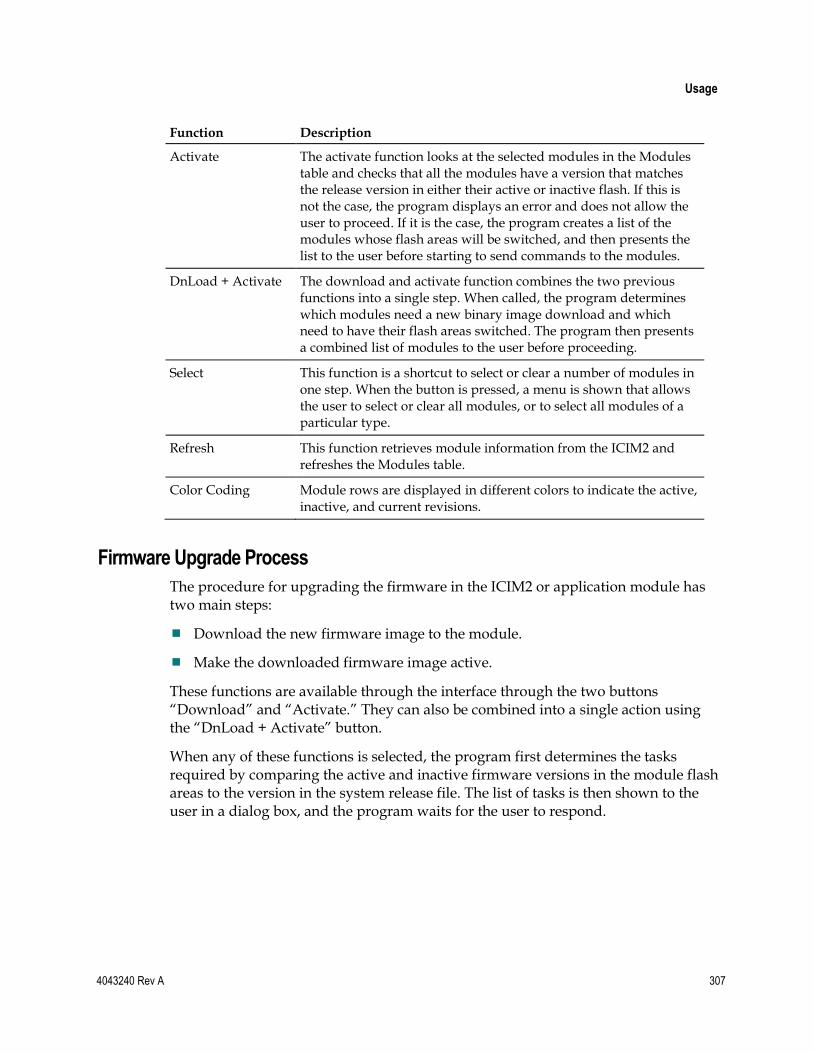
Usage
4043240 Rev A 307
Function Description
Activate The activate function looks at the selected modules in the Modules table and checks that all the modules have a version that matches the release version in either their active or inactive flash. If this is not the case, the program displays an error and does not allow the user to proceed. If it is the case, the program creates a list of the modules whose flash areas will be switched, and then presents the list to the user before starting to send commands to the modules.
DnLoad + Activate The download and activate function combines the two previous functions into a single step. When called, the program determines which modules need a new binary image download and which need to have their flash areas switched. The program then presents a combined list of modules to the user before proceeding.
Select This function is a shortcut to select or clear a number of modules in one step. When the button is pressed, a menu is shown that allows the user to select or clear all modules, or to select all modules of a particular type.
Refresh This function retrieves module information from the ICIM2 and refreshes the Modules table.
Color Coding Module rows are displayed in different colors to indicate the active, inactive, and current revisions.
Firmware Upgrade Process
The procedure for upgrading the firmware in the ICIM2 or application module has two main steps:
Download the new firmware image to the module.
Make the downloaded firmware image active.
These functions are available through the interface through the two buttons “Download” and “Activate.” They can also be combined into a single action using the “DnLoad + Activate” button.
When any of these functions is selected, the program first determines the tasks required by comparing the active and inactive firmware versions in the module flash areas to the version in the system release file. The list of tasks is then shown to the user in a dialog box, and the program waits for the user to respond.
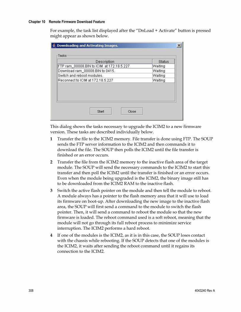
Chapter 10 Remote Firmware Download Feature
308 4043240 Rev A
For example, the task list displayed after the “DnLoad + Activate” button is pressed might appear as shown below.
This dialog shows the tasks necessary to upgrade the ICIM2 to a new firmware version. These tasks are described individually below.
1 Transfer the file to the ICIM2 memory. File transfer is done using FTP. The SOUP sends the FTP server information to the ICIM2 and then commands it to download the file. The SOUP then polls the ICIM2 until the file transfer is finished or an error occurs.
2 Transfer the file from the ICIM2 memory to the inactive flash area of the target module. The SOUP will send the necessary commands to the ICIM2 to start this transfer and then poll the ICIM2 until the transfer is finished or an error occurs. Even when the module being upgraded is the ICIM2, the binary image still has to be downloaded from the ICIM2 RAM to the inactive flash.
3 Switch the active flash pointer on the module and then tell the module to reboot. A module always has a pointer to the flash memory area that it will use to load its firmware on boot-up. After downloading the new image to the inactive flash area, the SOUP will first send a command to the module to switch the flash pointer. Then, it will send a command to reboot the module so that the new firmware is loaded. The reboot command used is a soft reboot, meaning that the module will not go through its full reboot process to minimize service interruption. The ICIM2 performs a hard reboot.
4 If one of the modules is the ICIM2, as it is in this case, the SOUP loses contact with the chassis while rebooting. If the SOUP detects that one of the modules is the ICIM2, it waits after sending the reboot command until it regains its connection to the ICIM2.

Usage
4043240 Rev A 309
FTP Settings
To upgrade firmware for Prisma II application modules, an FTP server is needed to transfer system release files and firmware binary images. When the SOUP is launched from a network management system (NMS), information about the FTP server must be passed to it in the command line. When launched as a standalone application using SOUPLauncher, this information is requested from the user.
Specifically, the SOUP needs the FTP server address, the user and password to log into the server, and an optional subdirectory path for the location of the system release files. If the SOUP is running in Administrator level, you can look at and change these settings by first clicking on Settings in the main menu bar, and then choosing FTP Server.
A dialog box displaying the FTP server information opens, allowing you to change and test the settings.
The table below describes the fields in the FTP Settings dialog box.
Item Description
FTP Server Address The address of the FTP server. This can be an IP address or a name that can be resolved by the computer running the SOUP.
Directory on FTP Server
The path to the system release files within the FTP server; for example, /dload/Prisma2.
User The user name to log into the FTP server.
Password The password to log into the FTP server.

Chapter 10 Remote Firmware Download Feature
310 4043240 Rev A
Item Description
Timeout (sec) Timeout to prevent SOUP from hanging up due to an FTP file transfer problem. The timeout value is adjustable from 1 to 180 seconds; the default value is 180.
SNMP Settings
SNMP Settings are passed to the SOUP utility by an NMS as command line parameters. If launched using SOUPLauncher, this information is retrieved from the ICIM2 after a successful login.
To connect to the ICIM2 through SNMP, the SOUP utility needs the SNMP Read and Write community strings. If the SOUP is running in Administrator mode, you can browse and change the SNMP settings by first clicking on Settings in the main menu bar, and then choosing SNMP Settings.
The SNMP Settings dialog appears as shown in the following illustration.
In addition to the Read and Write community strings, the Administrator can change:
The timeout value (in milliseconds) to use when communicating with the ICIM2.
The number of retries for SNMP messages.
These two settings are saved locally by the SOUP utility.
Usage
4043240 Rev A 311
FTP Server
The SOUP utility and the ICIM2 work together with an FTP server to perform firmware upgrades. The FTP server makes the binary image files available to the ICIM2 and acts as a repository for system release files. The only requirement for the FTP server is that it be accessible through TCP/IP by both the SOUP and the ICIM2.
Consult your system administrator for details on how to configure an FTP server for this application.
Note: If the ICIM2 has IPsec enabled, the FTP server must also be set up for IPsec and included in the ICIM2 list of IPsec peers.
Chapter 10 Remote Firmware Download Feature
312 4043240 Rev A
Firmware Updates New system release files are distributed when a firmware update becomes available. System release files package the firmware binary images for the different modules and provide version information for those images. These files are produced and distributed by the manufacturer, and are not intended to be created or modified by end users in any manner.
CAUTION:
Do not try to perform a firmware update that would result in downgrading ICIM2 or ICIM2-XD firmware below system release 2.02.09. Earlier system releases may incorrectly identify the ICIM2 or ICIM2-XD slot number and fail to connect with the ICIM2 or ICIM2-XD when completing the download.
The following is a sample system release file. The information contained in the XML file is listed in the table below.
Item Description
PrismaIIRelease The root element in the file identifies this to be a Prisma II system release file.
ReleaseDate The official release date.
Name A descriptive name for the system release, typically a system version number.

Firmware Updates
4043240 Rev A 313
Item Description
Module One or more module elements containing information about the versions contained in this system release file for a particular module type.
TypeNo – The target module type number.
Version – The version of the firmware for the module.
Filename – The file name of the binary image holding the module firmware.
Boot – An element containing information about the boot image necessary to run this version of the firmware (ICIM2 or ICIM2-XD only).
– Version – The version of the boot image.
– Filename – The file name that holds the boot image.
Depends – An optional element containing information about dependencies of this version of the firmware to other modules and their version. These elements are used to make sure that when an upgrade is performed, any dependencies across modules are enforced.
– TypeNo – The type number of the module depended on.
– Version – The version of the firmware necessary in the module on which it depends.
– VersionEq – A comparison operator to use when looking at the version in the module. This can either be Equal for strict equality, or EqualOrGreater to accept a matching or newer version.

Chapter 10 Remote Firmware Download Feature
314 4043240 Rev A

4043240 Rev A 315
Introduction
Internet Protocol security (IPsec) is a suite of standards and protocols that provides security, confidentiality, authentication, and protection from replay attacks, i.e., the repeated or delayed transmission of data for the purpose of defeating network security.
IPsec provides security for all IP-based communication. This makes it unnecessary to build separate security into ftp, Telnet, SNMP, and other similar applications.
This chapter explains how to set up the ICIM (ICIM2 or ICIM2-XD) and the Windows or Solaris computers to use IPsec with preshared keys. Preshared keys are the only form of internet key exchange (IKE) currently supported by the ICIM.
11 Chapter 11 Setting Up IPsec
In This Chapter
IPsec Overview .................................................................................... 316
Configuring IPsec on the ICIM ......................................................... 318
Configuring IPsec on Windows ........................................................ 321
Configuring IPsec on Solaris ............................................................. 344

Chapter 11 Setting Up IPsec
316 4043240 Rev A
IPsec Overview IPsec ensures secure communication by providing authentication and encryption mechanisms for network traffic between two peer computers.
IPsec can use several different encryption and authentication mechanisms to accommodate various implementations and security needs. To ensure that two peer computers use the same protocols when communicating with each other, a policy is set up that defines a set of security parameters and encryption algorithms that can be configured in each of the peer computers.
This chapter describes the possible IPsec configuration options and values in the ICIM, and provides step-by-step procedures for configuring IPsec on the ICIM, Windows, and Solaris.
Key Exchange
When an IPsec session is established, the peer computers need to exchange encryption keys in a secure way. The ICIM uses Internet Key Exchange (IKE) for this purpose. IKE is configured to use preshared keys that can be set by the user. IKE will use 3DES encryption and MD5 hashing.
IPsec Packets
After a key is exchanged, the peer computers negotiate the structure of the IP packets. IPsec modifies IP packets between the two peer computers by adding optional headers and encrypting the data. Potentially, two headers can be used for this purpose: the Authentication Header (AH) and the Encapsulated Security Payload Header (ESP). To meet current requirements, however, the ICIM uses only ESP; AH is not used.
When using ESP, two options ensure data integrity: the encryption algorithm (3DES) and the hashing algorithm (MD5). The ICIM is configured to accept a number of ESP "proposals," that is, a number of combinations of encryption and hashing algorithms. These combinations are listed below.
Encryption Hashing
None MD5
None SHA
3DES None
AES - 128 bits None
AES - 128 bits MD5
3DES MD5

IPsec Overview
4043240 Rev A 317
Note: To establish a network session, the computer communicating with the ICIM must support at least one of the above combinations.
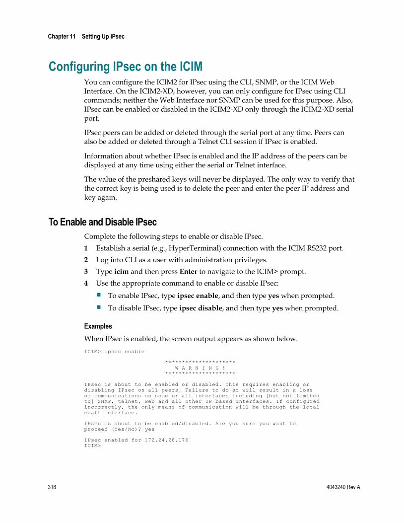
Chapter 11 Setting Up IPsec
318 4043240 Rev A
Configuring IPsec on the ICIM You can configure the ICIM2 for IPsec using the CLI, SNMP, or the ICIM Web Interface. On the ICIM2-XD, however, you can only configure for IPsec using CLI commands; neither the Web Interface nor SNMP can be used for this purpose. Also, IPsec can be enabled or disabled in the ICIM2-XD only through the ICIM2-XD serial port.
IPsec peers can be added or deleted through the serial port at any time. Peers can also be added or deleted through a Telnet CLI session if IPsec is enabled.
Information about whether IPsec is enabled and the IP address of the peers can be displayed at any time using either the serial or Telnet interface.
The value of the preshared keys will never be displayed. The only way to verify that the correct key is being used is to delete the peer and enter the peer IP address and key again.
To Enable and Disable IPsec
Complete the following steps to enable or disable IPsec.
1 Establish a serial (e.g., HyperTerminal) connection with the ICIM RS232 port.
2 Log into CLI as a user with administration privileges.
3 Type icim and then press Enter to navigate to the ICIM> prompt.
4 Use the appropriate command to enable or disable IPsec:
To enable IPsec, type ipsec enable, and then type yes when prompted.
To disable IPsec, type ipsec disable, and then type yes when prompted.
Examples
When IPsec is enabled, the screen output appears as shown below.
ICIM> ipsec enable
********************* W A R N I N G ! *********************
IPsec is about to be enabled or disabled. This requires enabling or disabling IPsec on all peers. Failure to do so will result in a loss of communications on some or all interfaces including [but not limited to] SNMP, telnet, web and all other IP based interfaces. If configured incorrectly, the only means of communication will be through the local craft interface.
IPsec is about to be enabled/disabled. Are you sure you want to proceed (Yes/No)? yes
IPsec enabled for 172.24.28.176 ICIM>

Configuring IPsec on the ICIM
4043240 Rev A 319
When IPsec is disabled, the screen output is similar:
CLI> icim ICIM> ipsec disable
********************* W A R N I N G ! *********************
IPsec is about to be enabled or disabled. This requires enabling or disabling IPsec on all peers. Failure to do so will result in a loss of communications on some or all interfaces including [but not limited to] SNMP, telnet, web and all other IP based interfaces. If configured incorrectly, the only means of communication will be through the local craft interface.
IPsec is about to be enabled/disabled. Are you sure you want to proceed (Yes/No)? yes
IPsec disabled for 172.24.28.176 ICIM>
To Add or Delete an IPsec Peer
To add or delete an IPsec peer, you must first establish a HyperTerminal CLI session as instructed in To Set Up a HyperTerminal Serial Port Session (on page 86). Or, if IPsec is enabled, you can set up a Telnet CLI session as described in Telnet Session (on page 94).
Note: To be able to add or delete an IPsec peer, you must log in as a user with Admin level privileges.
Add an IPsec Peer
From the CLI> prompt, complete the following steps to add an IPsec peer.
1 Type icim, and then press Enter to access the ICIM> command prompt.
2 Type ike add xxx.xxx.xxx.xxx, where the string xxx.xxx.xxx.xxx is the IP address of the peer (for example, 172.24.28.123), and then press Enter.
3 When prompted by the system, enter the preshared key value, and then press Enter.
Note:
The preshared key value must be an alphanumeric string exactly 16 characters long. This value must exactly match the key used on the peer being added.
For security, the preshared key value is not displayed on the screen as you type. The system will ask you to reenter the key to confirm correct entry.
4 When prompted by the system, enter the preshared key value again, and then press Enter. The new IPsec peer is added.

Chapter 11 Setting Up IPsec
320 4043240 Rev A
Delete an IPsec Peer
From the CLI> prompt, complete the following steps to delete an IPsec peer.
1 Type icim, and then press Enter to access the ICIM> command prompt.
2 Type ike delete xxx.xxx.xxx.xxx, where the string xxx.xxx.xxx.xxx is the IP address of the peer (for example, 172.24.28.123), and then press Enter.
Example
The following example shows the screen output as an IPsec peer at 172.24.28.123 with a preshared key of TestKey890123456 (never displayed onscreen) is added and then deleted.
CLI> icim
ICIM> ike add 172.24.28.123
Please enter the key:
Please reenter the key:
SUCCESS!
ICIM> ike delete 172.24.28.123
SUCCESS!
Note: IPsec must be enabled on the ICIM in order to delete an IKE peer.
To Display IPsec Information
Complete the following steps to display information on IPsec.
1 Establish a HyperTerminal or Telnet session using the instructions in To Set Up a HyperTerminal Serial Port Session (on page 86).
2 Log in and navigate to the ICIM> prompt.
3 Type show ike to display whether IPsec is currently enabled or disabled and list the IP addresses of all IPsec peers.

Configuring IPsec on Windows
4043240 Rev A 321
Configuring IPsec on Windows Note: You must be an Admin user to perform this procedure.
Windows can be configured to use IPsec using the Microsoft Management Console (MMC). The MMC is a generic management console that can manage many different Windows components.
IPsec configuration in Windows consists of four main tasks:
Access the IPsec management console.
Create IP address lists to identify computers.
Create Filter actions to define encryption parameters.
Create Policies that put IP address lists and filter actions together.
Each of these tasks is described below.
Note: The screens shown below were captured under Windows XP Professional v5.1. There may be slight differences in appearance between these screens and those appearing on your monitor, depending on the version of Windows you are running.
To Access the IPsec Management Console
Complete the following steps to open the IPsec management console.
Launch MMC
1 From the Windows desktop, click the Start button in the System Tray, and then choose Run… from the Start menu.
The Run dialog box appears as shown below.

Chapter 11 Setting Up IPsec
322 4043240 Rev A
2 Enter mmc in the text field, and then click OK.
The MMC main screen appears as shown below.

Configuring IPsec on Windows
4043240 Rev A 323
Add the Appropriate Snap-In
In order for MMC to manage the IPsec component, you must add the appropriate IPsec snap-in as follows:
1 From the File menu, choose Add/Remove Snap-in.
The Add/Remove Snap-in dialog appears as shown below.

Chapter 11 Setting Up IPsec
324 4043240 Rev A
2 Click the Add button.
The Add Standalone Snap-in dialog appears as shown below.
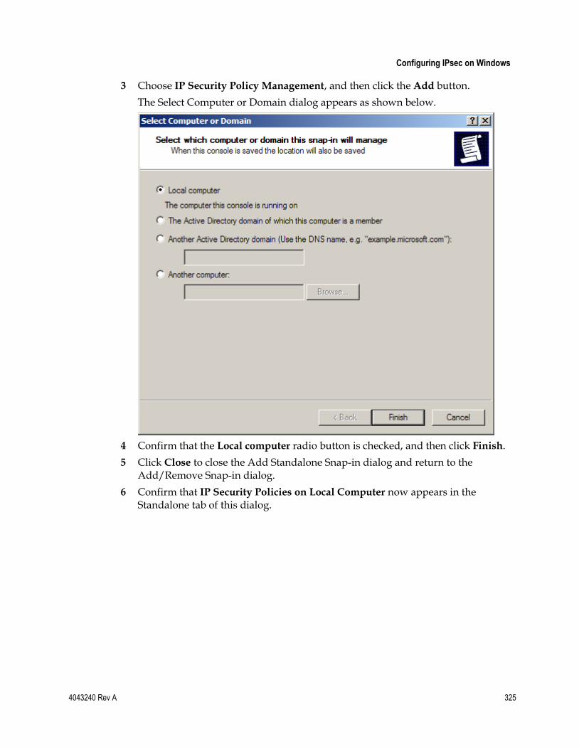
Configuring IPsec on Windows
4043240 Rev A 325
3 Choose IP Security Policy Management, and then click the Add button.
The Select Computer or Domain dialog appears as shown below.
4 Confirm that the Local computer radio button is checked, and then click Finish.
5 Click Close to close the Add Standalone Snap-in dialog and return to the Add/Remove Snap-in dialog.
6 Confirm that IP Security Policies on Local Computer now appears in the Standalone tab of this dialog.

Chapter 11 Setting Up IPsec
326 4043240 Rev A
7 Click OK to return to the management console.
The screen should now appear as shown below.
Note: If Console Root is highlighted in the left pane, click IP Security Policies on
Local Computer to display the options shown in the right pane above.

Configuring IPsec on Windows
4043240 Rev A 327
To Create a New IP List
Complete the following steps to create a new IP list.
1 In the left pane of the Management Console, right-click the IP Security Policies on Local Computer item.
2 Choose Manage IP filter lists and filter actions from the right-click menu.
The corresponding dialog appears as shown below.
3 Click the Add button to open the IP Filter List dialog.
Note that the default name New IP Filter List appears in the Name field.

Chapter 11 Setting Up IPsec
328 4043240 Rev A
4 In the Name field, replace the default name with a new list name that is meaningful to you (ICIM IPs in the example below).
5 Confirm that the Use Add Wizard checkbox is checked, and then click the Add button to start the IP filter list wizard.
6 Complete the steps of the wizard as follows:
a Traffic Source. This identifies the source of IP traffic for this list. Choose My IP Address from the drop-down list, and then click Next.
b IP Traffic Destination. This identifies the destination of the IP traffic for this list. Choose A specific IP Address from the drop-down list, then enter the ICIM IP address in the field provided, and then click Next.
c IP Protocol Type. This identifies what protocols are valid for this list. Choose Any from the drop-down list, and then click Next.

Configuring IPsec on Windows
4043240 Rev A 329
d Click Finish.
7 The IP Filter List dialog should now appear as shown below.
8 Click OK to return to the Manage IP filter lists and filter actions dialog.
9 Confirm that the new IP list now appears in the IP filter lists window.

Chapter 11 Setting Up IPsec
330 4043240 Rev A
To Create a New Filter Action
Complete the following steps to create a new filter action.
1 Click the Manage Filter Actions tab to show current filter actions and to add a new entry for the ICIM.
The tab opens as shown below.
2 Click the Add button to start the Filter Action wizard.
3 At the wizard welcome screen, click Next.
4 Complete the steps of the wizard as follows:
a Filter Action Name. Replace the default name New Filter Action with a meaningful name for the new action (e.g., ICIM IPsec Filter), and then click Next.
b Filter Action General Options. Check the Negotiate Security radio button, and then click Next.
c Communicating with computers that do not support IPsec. Choose Do not
communicate with computers that do not support IPsec, and then click Next.

Configuring IPsec on Windows
4043240 Rev A 331
d IP Traffic Security. Check the Custom radio button, and then click the Settings button.
The Custom Security Method Settings dialog appears as shown below.
e Check Data integrity and encryption (ESP), and then select MD5 and 3DES from the Integrity algorithm and Encryption algorithm drop-down menus, respectively.
f Click OK to save your selections and return to the Filter Action wizard IP Traffic Security wizard page.
g Click Next to proceed to the final page of the Filter Action wizard.

Chapter 11 Setting Up IPsec
332 4043240 Rev A
h Click Finish.
The new filter action should now appear in the Filter Actions list as shown below.
5 Double-click the filter action you just created to open the ICIM IPsec Filter Properties dialog.

Configuring IPsec on Windows
4043240 Rev A 333
6 On the Security Methods tab, confirm that the Session key perfect forward secrecy box is checked and the other boxes are cleared, as shown below.

Chapter 11 Setting Up IPsec
334 4043240 Rev A
7 When finished, click OK to close the ICIM IPsec Properties dialog and return to the Manage IP filter lists and filter actions dialog.
8 Click the Close button to close this dialog and return to the MMC screen.

Configuring IPsec on Windows
4043240 Rev A 335
To Create a New IPsec Policy
Complete the following steps to create a new IPsec policy.
1 Right-click the right pane of the MMC, and then click Create IP Security Policy. to open the IP Security Policy wizard.
2 At the wizard welcome screen, click Next to continue, and then complete the steps of the wizard as follows:

Chapter 11 Setting Up IPsec
336 4043240 Rev A
a IP Security Policy Name. In the Name field, replace the default policy name with a name that is more meaningful to you (e.g., ICIM Policy), and then click Next.
b Requests for Secure Communication. Confirm that the Activate the default response rule checkbox is checked, and then click Next.
c Default Response Rule Authentication Method. Confirm that Activate Directory Default (Kerberos V5 Protocol) is selected, and then click Next.

Configuring IPsec on Windows
4043240 Rev A 337
d On the final page of the wizard, confirm that the Edit Properties checkbox is checked, and then click Finish.
The ICIM Policy Properties dialog appears as shown below.
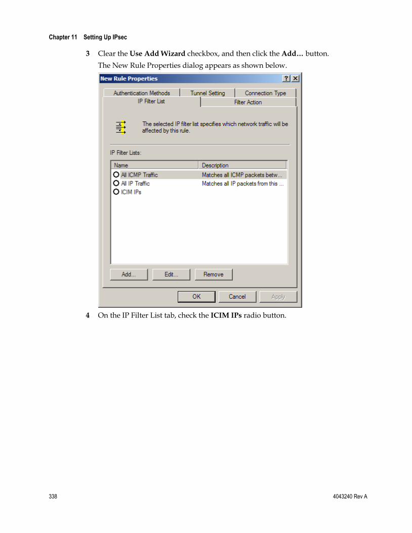
Chapter 11 Setting Up IPsec
338 4043240 Rev A
3 Clear the Use Add Wizard checkbox, and then click the Add… button.
The New Rule Properties dialog appears as shown below.
4 On the IP Filter List tab, check the ICIM IPs radio button.

Configuring IPsec on Windows
4043240 Rev A 339
5 On the Filter Action tab, check the ICIM IPSec Filter radio button.

Chapter 11 Setting Up IPsec
340 4043240 Rev A
6 Click the Authentication Methods tab, and then click the Add button.
The New Authentication Method Properties dialog appears as shown below.
7 Click the Use this string (preshared key) radio button, and then enter a 16-character alphanumeric string.
Note: Be sure to make a note of this string, as it must exactly match the preshared key entered in the ICIM.
8 Click OK to save the preshared key entry and return to the New Rule Properties dialog.
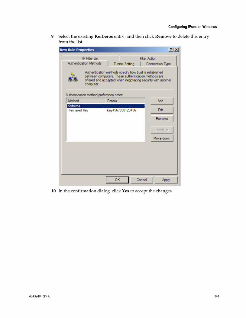
Configuring IPsec on Windows
4043240 Rev A 341
9 Select the existing Kerberos entry, and then click Remove to delete this entry from the list.
10 In the confirmation dialog, click Yes to accept the changes.

Chapter 11 Setting Up IPsec
342 4043240 Rev A
11 Click OK to close the New Rule Properties dialog.
The ICIM Policy Properties dialog should now display only the newly entered rule.
12 Close the dialog to return to the MMC. Confirm that the new policy now appears on the right pane.
13 Right-click the new policy, and then choose Assign to activate the policy.
If all of the above steps were performed correctly, the computer will now require IPsec to talk to the ICIM.
Note: If you have difficulty communicating with the ICIM after completing this procedure, ask your system administrator for assistance.
To Unassign IPsec
To disable IPsec on a Windows computer, you must unassign the IPsec policy as follows:
1 Access the ICIM Policy Properties dialog as described above.
2 Clear the check box beside the policy to be unassigned.
3 Click OK to save the change.
4 Reboot the computer.

Configuring IPsec on Windows
4043240 Rev A 343
Note: In some cases, it may be necessary to reassign an IPsec policy after you reboot. See your system administrator for assistance if needed.
For Further Information
Additional information on configuring IPsec for Windows is available on the following web page:
http://www.microsoft.com/downloads/details.aspx?familyid=a774012a-ac25-4a1d-8851-b7a09e3f1dc9&displaylang=en

Chapter 11 Setting Up IPsec
344 4043240 Rev A
Configuring IPsec on Solaris Note: You must be a root level user to perform this procedure.
To configure Solaris for IPsec, you must modify a number of files and then run a configuration program to activate the settings in these files.
The file /etc/inet/ipsecinit.conf holds the IPsec policy information.
Two files, /etc/inet/ike/config and /etc/inet/secret/ike.preshared, contain configuration information for IKE (the key exchange).
The program used to activate IPsec is called /usr/sbin/ipsecconf. Options when running this program include the following:
Option Description
ipsecconf –f Flush (clears) the current IPsec configuration.
ipsecconf –a <file> Loads a configuration file.
ipsecconf Shows the current IPsec configuration.
Solaris Configuration Files
IPsec configuration for Solaris involves two types of Solaris configuration files: the policy description file and the IKE setup files.
Policy Description File
The file /etc/inet/ipsecinit.conf holds all the IP lists and filters which together form the policy. The file contains a set of rules that describe how to handle IP traffic between source and destination addresses. Each line in the file represents one rule, and is generally of the form shown below.
{raddr 172.24.28.193/32} ipsec {encr_algs 3des encr_auth_algs md5}
Indicates two-way communication with ICIM
ICIM IP Address TP646
Indicates the encryption properties to be used for IPsec
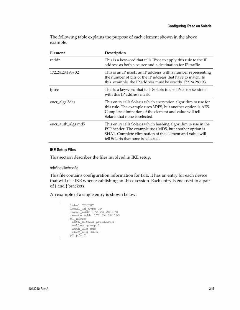
Configuring IPsec on Solaris
4043240 Rev A 345
The following table explains the purpose of each element shown in the above example.
Element Description
raddr This is a keyword that tells IPsec to apply this rule to the IP address as both a source and a destination for IP traffic.
172.24.28.193/32 This is an IP mask: an IP address with a number representing the number of bits of the IP address that have to match. In this example, the IP address must be exactly 172.24.28.193.
ipsec This is a keyword that tells Solaris to use IPsec for sessions with this IP address mask.
encr_algs 3des This entry tells Solaris which encryption algorithm to use for this rule. The example uses 3DES, but another option is AES. Complete elimination of the element and value will tell Solaris that none is selected.
encr_auth_algs md5 This entry tells Solaris which hashing algorithm to use in the ESP header. The example uses MD5, but another option is SHA1. Complete elimination of the element and value will tell Solaris that none is selected.
IKE Setup Files
This section describes the files involved in IKE setup.
/etc/inet/ike/config
This file contains configuration information for IKE. It has an entry for each device that will use IKE when establishing an IPsec session. Each entry is enclosed in a pair of { and } brackets.
An example of a single entry is shown below.
{ label "ICIM" local_id_type IP local_addr 172.24.28.178 remote_addr 172.24.28.193 p1_xform{ auth_method preshared oakley_group 2 auth_alg md5 encr_alg 3des} p2_pfs 2 }
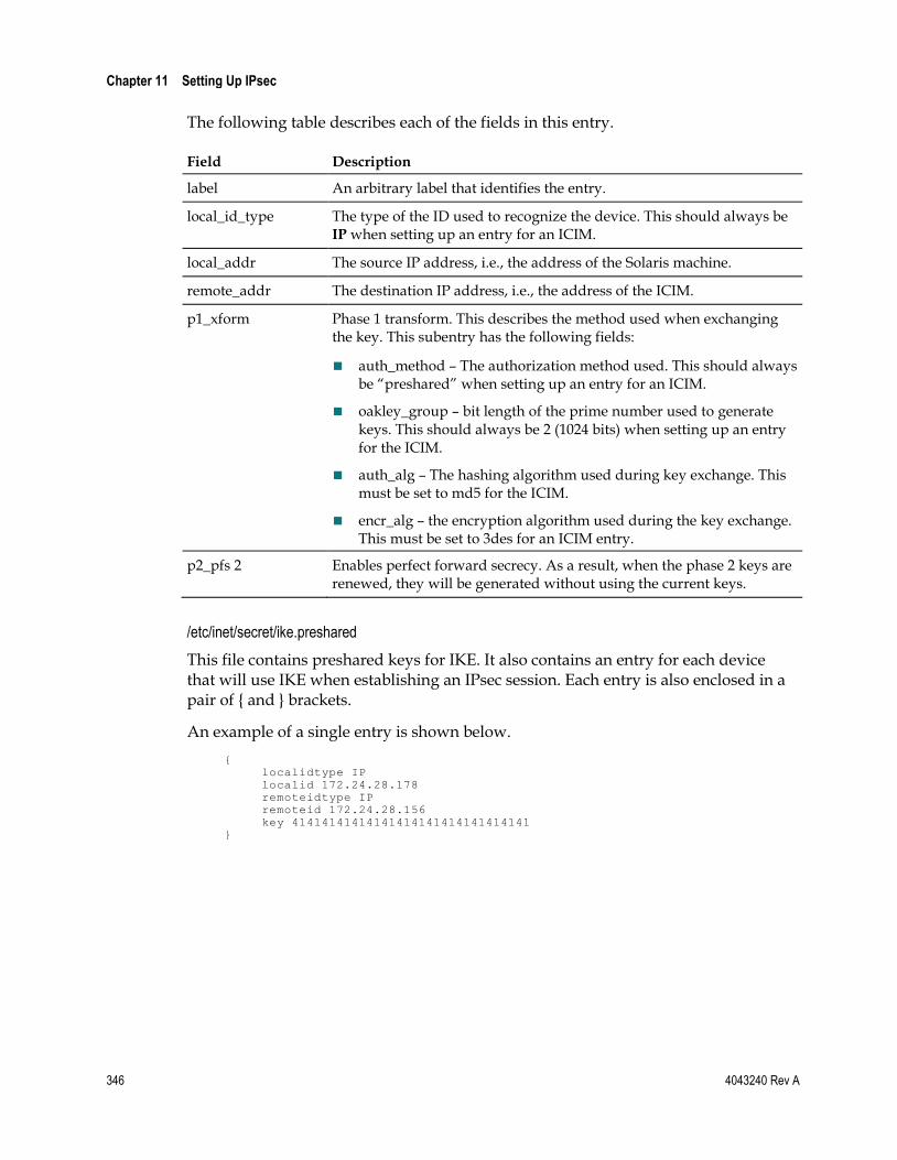
Chapter 11 Setting Up IPsec
346 4043240 Rev A
The following table describes each of the fields in this entry.
Field Description
label An arbitrary label that identifies the entry.
local_id_type The type of the ID used to recognize the device. This should always be IP when setting up an entry for an ICIM.
local_addr The source IP address, i.e., the address of the Solaris machine.
remote_addr The destination IP address, i.e., the address of the ICIM.
p1_xform Phase 1 transform. This describes the method used when exchanging the key. This subentry has the following fields:
auth_method – The authorization method used. This should always be “preshared” when setting up an entry for an ICIM.
oakley_group – bit length of the prime number used to generate keys. This should always be 2 (1024 bits) when setting up an entry for the ICIM.
auth_alg – The hashing algorithm used during key exchange. This must be set to md5 for the ICIM.
encr_alg – the encryption algorithm used during the key exchange. This must be set to 3des for an ICIM entry.
p2_pfs 2 Enables perfect forward secrecy. As a result, when the phase 2 keys are renewed, they will be generated without using the current keys.
/etc/inet/secret/ike.preshared
This file contains preshared keys for IKE. It also contains an entry for each device that will use IKE when establishing an IPsec session. Each entry is also enclosed in a pair of { and } brackets.
An example of a single entry is shown below.
{ localidtype IP localid 172.24.28.178 remoteidtype IP remoteid 172.24.28.156 key 41414141414141414141414141414141 }

Configuring IPsec on Solaris
4043240 Rev A 347
The following table describes each of the fields in this entry.
Field Description
localidtype The type of ID used to identify the Solaris machine. Normally this should be set to IP.
localid The source IP address, i.e., the address of the Solaris machine.
remoteidtype Type ID used to identify the remote device. This should always be IP when setting up and entry for an ICIM.
remoteid The remote IP address, i.e., the address of the ICIM.
key The preshared key. The key is entered as a string of two-digit hexadecimal values representing ASCII characters. In the example above, 41 is the hexadecimal equivalent of 65, the ASCII decimal equivalent of the uppercase A character. Therefore, the key value shown above represents the string AAAAAAAAAAAAAAAA.
Had the ICIM IPsec key been entered as 1234567890123456, the Solaris /etc/inet/secret/ike.preshared file key would appear as follows:
key 31323334353637383930313233343536
where 31 is the hexadecimal equivalent of the ASCII value of the character 1, 32 is the hex equivalent of ASCII 2, and so on.
Note: Tables for converting ASCII characters to hex equivalents are available from many sources on the internet.
Implementing the Changes
In order for these changes to take effect, the IKE daemon must be "killed" (stopped) and then restarted as follows:
1 At the Unix shell prompt, type pkill in.iked, and then press Enter to stop the IKE daemon.
2 At the prompt, type /usr/lib/inet/in.iked, and then press Enter to restart the IKE daemon.
The changes to the IKE configuration should now be in effect.

Chapter 11 Setting Up IPsec
348 4043240 Rev A
To Configure IPsec on Solaris
Complete the following steps to configure IPsec on Solaris.
1 Modify /etc/inet/ipsecinit.conf to add entries for each ICIM that will use IPsec.
2 Modify /etc/inet/ike/config to add an entry for each ICIM that will use IPsec.
3 Modify /etc/inet/secret/ike.preshared to enter the preshared keys for each ICIM that will use IPsec.
4 Flush any current IPsec configuration by executing ipsecconf –f.
5 Stop the IKE daemon by issuing the command pkill in.iked.
6 Restart the IKE daemon by issuing the command /usr/lib/inet/in.iked.
7 Activate the IPsec configuration by executing ipsecconf –a /etc/inet/ipsecinit.conf.
To test this connection, open a web browser and confirm that you can use it to communicate with the ICIM.
Note: If a syntax error occurs stating that the input string is too long, reopen the /etc/inet/ipsecinit.conf and /etc/inet/ike/config files, remove any space characters at the ends of the files, and then save the files and retry.
To Disable IPsec
To disable IPsec on Solaris, issue the command ipsecconf –s.
References
For more detail on configuring IPsec on Solaris, go to http://www.securityfocus.com/infocus/1616.

4043240 Rev A 349
Introduction
This chapter provides information to assist you in maintaining and troubleshooting the platform.
Qualified Personnel
Only appropriately qualified and skilled personnel should attempt to maintain or troubleshoot chassis faults.
WARNING:
Allow only qualified and skilled personnel to install, operate, maintain, and service these products. Otherwise, personal injury or equipment damage may occur.
12 Chapter 12 Maintenance and
Troubleshooting

Chapter 12 Maintenance and Troubleshooting
350 4043240 Rev A
In This Chapter
Maintenance ........................................................................................ 351
Troubleshooting .................................................................................. 352
FansOk Alarm ..................................................................................... 354
ChasTemp Alarm ................................................................................ 355
Ps1PwrIn Alarm .................................................................................. 357
Ps1+24 Alarm ...................................................................................... 358
Ps1+5VDC Alarm ................................................................................ 359
Ps1-5VDC Alarm ................................................................................. 360
Ps3PwrIn Alarm .................................................................................. 361
Ps3+24 Alarm ...................................................................................... 362
Ps3+5VDC Alarm ................................................................................ 363
Ps3-5VDC Alarm ................................................................................. 364
Cleaning Optical Connectors ............................................................ 365
Connecting Optical Cables ................................................................ 367
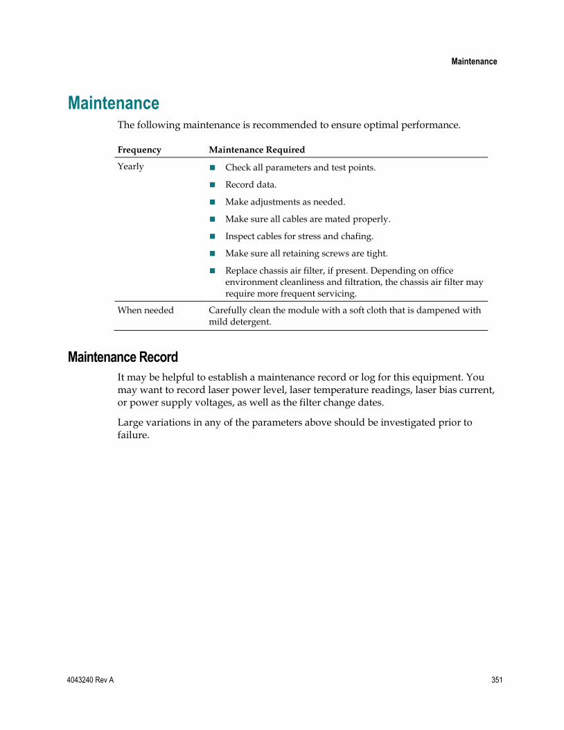
Maintenance
4043240 Rev A 351
Maintenance The following maintenance is recommended to ensure optimal performance.
Frequency Maintenance Required
Yearly Check all parameters and test points.
Record data.
Make adjustments as needed.
Make sure all cables are mated properly.
Inspect cables for stress and chafing.
Make sure all retaining screws are tight.
Replace chassis air filter, if present. Depending on office environment cleanliness and filtration, the chassis air filter may require more frequent servicing.
When needed Carefully clean the module with a soft cloth that is dampened with mild detergent.
Maintenance Record
It may be helpful to establish a maintenance record or log for this equipment. You may want to record laser power level, laser temperature readings, laser bias current, or power supply voltages, as well as the filter change dates.
Large variations in any of the parameters above should be investigated prior to failure.

Chapter 12 Maintenance and Troubleshooting
352 4043240 Rev A
Troubleshooting This section provides general information on servicing and troubleshooting this equipment. The troubleshooting information describes the most common alarms and gives typical symptoms, causes, and items to check before contacting Customer Service.
Chassis Troubleshooting
The main function of the chassis is to distribute power and establish communication links for the application modules installed in the chassis. Most troubleshooting involves the modules installed in the chassis, but in some instances, you will need to troubleshoot the chassis itself.
The table below describes the most common problems and gives typical symptoms, possible causes, and items to check before contacting Customer Service.
WARNING:
Avoid electric shock and damage to this product! Do not open the enclosure of this product. There are no user-serviceable parts inside. Refer servicing to qualified service personnel.
Symptom Possible Causes Solutions
ON indicator is not illuminated
Power supply connection loose
Check that all power supply connections are secure.
Loss of system power Check that power is present at receptacle.
Power failure; backup in use Check other displays and indicators for power indication.
Module indicator burned out Contact Customer Service for an indicator replacement.
ALARM indicator is on or flashing
Application module in alarm Consult network management system (NMS) for module alarms (see module documentation for details).
Chassis failed power-up self-test
Check that all power supply connections are secure.
Check Power On and Alarm LED indicators on power supplies.

Troubleshooting
4043240 Rev A 353
ICIM indicator is off ICIM not installed or not fully seated
Confirm that chassis is part of an ICIM daisy chain (no need for separate ICIM).
If not, check that the ICIM is fully seated in back of chassis.
Alarm Troubleshooting
The Prisma II Platform generates certain alarms that are specific to the chassis, its fan assembly, and its power supply components.
Parameter Function
FansOk Fan tray operating status
ChasTemp Fan tray internal temperature
Ps1PwrIn Power supply slot 1 input power
Ps1+24 Power supply slot 1 +24 VDC output voltage
Ps1+5VDC Power supply slot 1 +5 VDC output voltage
Ps1-5VDC Power supply slot 1 -5 VDC output voltage
Ps3PwrIn Power supply slot 3 input power
Ps3+24 Power supply slot 3 +24 VDC output voltage
Ps3+5VDC Power supply slot 3 +5 VDC output voltage
Ps3-5VDC Power supply slot 3 -5 VDC output voltage
Troubleshooting information for each of these alarms is provided in the following sections of this chapter.
Other alarms may occur as a result of fault conditions in specific application modules. For information on troubleshooting alarms for specific application modules, see the appropriate module documentation.
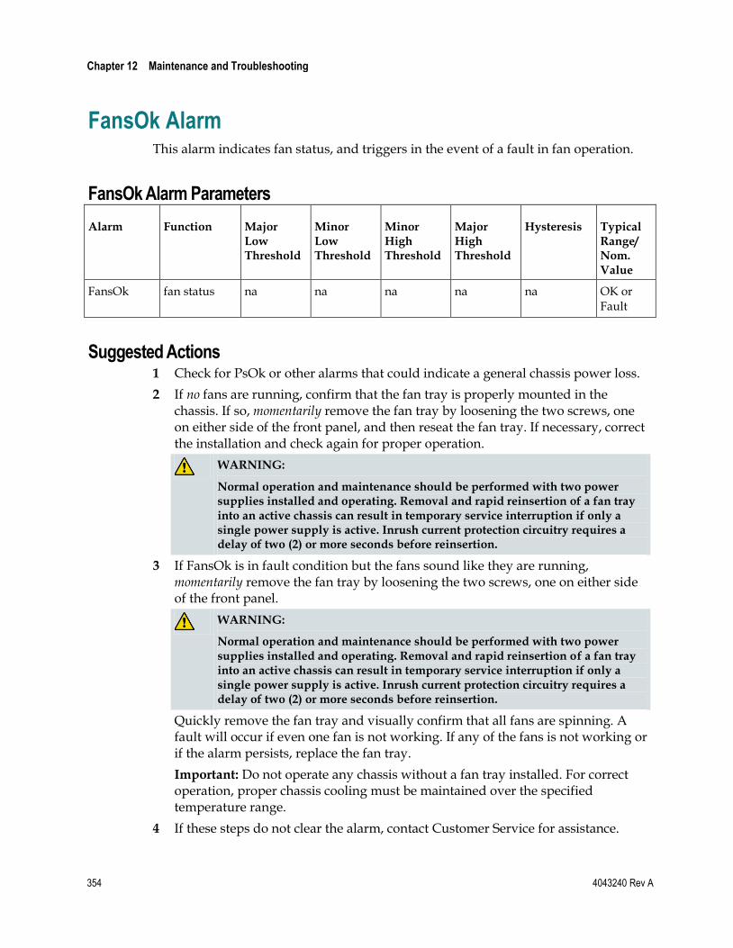
Chapter 12 Maintenance and Troubleshooting
354 4043240 Rev A
FansOk Alarm This alarm indicates fan status, and triggers in the event of a fault in fan operation.
FansOk Alarm Parameters
Alarm Function Major Low Threshold
Minor Low Threshold
Minor High Threshold
Major High Threshold
Hysteresis Typical Range/ Nom. Value
FansOk fan status na na na na na OK or Fault
Suggested Actions 1 Check for PsOk or other alarms that could indicate a general chassis power loss.
2 If no fans are running, confirm that the fan tray is properly mounted in the chassis. If so, momentarily remove the fan tray by loosening the two screws, one on either side of the front panel, and then reseat the fan tray. If necessary, correct the installation and check again for proper operation.
WARNING:
Normal operation and maintenance should be performed with two power supplies installed and operating. Removal and rapid reinsertion of a fan tray into an active chassis can result in temporary service interruption if only a single power supply is active. Inrush current protection circuitry requires a delay of two (2) or more seconds before reinsertion.
3 If FansOk is in fault condition but the fans sound like they are running, momentarily remove the fan tray by loosening the two screws, one on either side of the front panel.
WARNING:
Normal operation and maintenance should be performed with two power supplies installed and operating. Removal and rapid reinsertion of a fan tray into an active chassis can result in temporary service interruption if only a single power supply is active. Inrush current protection circuitry requires a delay of two (2) or more seconds before reinsertion.
Quickly remove the fan tray and visually confirm that all fans are spinning. A fault will occur if even one fan is not working. If any of the fans is not working or if the alarm persists, replace the fan tray.
Important: Do not operate any chassis without a fan tray installed. For correct operation, proper chassis cooling must be maintained over the specified temperature range.
4 If these steps do not clear the alarm, contact Customer Service for assistance.
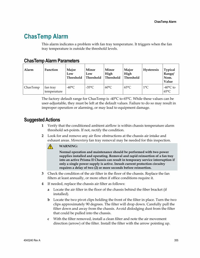
ChasTemp Alarm
4043240 Rev A 355
ChasTemp Alarm This alarm indicates a problem with fan tray temperature. It triggers when the fan tray temperature is outside the threshold levels.
ChasTemp Alarm Parameters
Alarm Function Major Low Threshold
Minor Low Threshold
Minor High Threshold
Major High Threshold
Hysteresis Typical Range/ Nom. Value
ChasTemp fan tray temperature
-40°C -35°C 60°C 65°C 1°C -40°C to 65°C
The factory default range for ChasTemp is -40°C to 65°C. While these values can be user-adjustable, they must be left at the default values. Failure to do so may result in improper operation or alarming, or may lead to equipment damage.
Suggested Actions 1 Verify that the conditioned ambient airflow is within chassis temperature alarm
threshold set-points. If not, rectify the condition.
2 Look for and remove any air flow obstructions at the chassis air intake and exhaust areas. Momentary fan tray removal may be needed for this inspection.
WARNING:
Normal operation and maintenance should be performed with two power supplies installed and operating. Removal and rapid reinsertion of a fan tray into an active Prisma II Chassis can result in temporary service interruption if only a single power supply is active. Inrush current protection circuitry requires a delay of two (2) or more seconds before reinsertion.
3 Check the condition of the air filter in the floor of the chassis. Replace the fan filters at least annually, or more often if office conditions require it.
4 If needed, replace the chassis air filter as follows:
a Locate the air filter in the floor of the chassis behind the fiber bracket (if installed).
b Locate the two pivot clips holding the front of the filter in place. Turn the two clips approximately 90 degrees. The filter will drop down. Carefully pull the filter down and away from the chassis. Avoid dislodging dust from the filter that could be pulled into the chassis.
c With the filter removed, install a clean filter and note the air movement direction (arrow) of the filter. Install the filter with the arrow pointing up.

Chapter 12 Maintenance and Troubleshooting
356 4043240 Rev A
d Note that two pins secure the rear of the filter. Install the filter above these pins, and then push upward.
e Press the filter upward.
f Rotate the two pivot clips to secure the front edge of the filter.
5 If these steps do not clear the alarm, contact Customer Service for assistance.

Ps1PwrIn Alarm
4043240 Rev A 357
Ps1PwrIn Alarm This alarm indicates the status of the line input voltage to the power supply installed in slot 1 of the chassis. It triggers in the event that the power supply input voltage is not in the voltage range recommended by the manufacturer.
Ps1PwrIn Alarm Parameters
Alarm Function Major Low Threshold
Minor Low Threshold
Minor High Threshold
Major High Threshold
Hysteresis Typical Range/ Nom. Value
Ps1PwrIn Slot 1 input power
na na na na na OK or Fault
Suggested Actions 1 Check the chassis power cord and confirm that the power supply in slot 1 is fully
seated.
2 If the line voltage is feeding only the alarming power supply, check the line for both proper voltage and polarity. If the line voltage and polarity are acceptable, replace the power supply module.
3 If the line voltage is feeding more than one chassis with no indication of Ps1PwrIn alarm on any other power supply, replace the alarming power supply module.
4 If these steps do not clear the alarm, contact Customer Service for assistance.

Chapter 12 Maintenance and Troubleshooting
358 4043240 Rev A
Ps1+24 Alarm This alarm indicates the status of the +24 V DC output voltage from the power supply installed in slot 1 of the chassis. It triggers when this output voltage is outside the threshold levels.
Ps1+24 Alarm Parameters
Alarm Function Major Low Threshold
Minor Low Threshold
Minor High Threshold
Major High Threshold
Hysteresis Typical Range/ Nom. Value
Ps1+24 Slot 1 +24 voltage
18.0 V DC 18.4 V DC 25.9 V DC 26.1 V DC 0.1 V DC 23.8 to 25.6 V DC
While the threshold values can be user-adjustable, they must be left at the default values. Failure to do so may result in improper operation or alarming, or may lead to equipment damage.
Suggested Actions 1 Confirm that the power supply in slot 1 is fully seated.
2 Confirm that the alarm is caused by the voltage exceeding or falling below factory-set threshold values. If so, replace the power supply module.
3 If these steps do not clear the alarm, contact Customer Service for assistance.

Ps1+5VDC Alarm
4043240 Rev A 359
Ps1+5VDC Alarm This alarm indicates the status of the +5 V DC output voltage from the power supply installed in slot 1 of the chassis. It triggers when this output voltage is outside the threshold levels.
Ps1+5VDC Alarm Parameters
Alarm Function Major Low Threshold
Minor Low Threshold
Minor High Threshold
Major High Threshold
Hysteresis Typical Range/ Nom. Value
Ps1+5VDC Slot 1 +5 voltage
3.6 V DC 3.7 V DC 5.9 V DC 6.1 V DC 0.1 V DC 4.9 to 5.3 V DC
While the threshold values can be user-adjustable, they must be left at the default values. Failure to do so may result in improper operation or alarming, or may lead to equipment damage.
Suggested Actions 1 Confirm that the power supply in slot 1 is fully seated.
2 Confirm that the alarm is caused by the voltage exceeding or falling below factory-set threshold values. If so, replace the power supply module.
3 If these steps do not clear the alarm, contact Customer Service for assistance.

Chapter 12 Maintenance and Troubleshooting
360 4043240 Rev A
Ps1-5VDC Alarm This alarm indicates the status of the -5 V DC output voltage from the power supply installed in slot 1 of the chassis. It triggers when this output voltage is outside the threshold levels.
PS1-5VDC Alarm Parameters
Alarm Function Major Low Threshold
Minor Low Threshold
Minor High Threshold
Major High Threshold
Hysteresis Typical Range/ Nom. Value
Ps1-5VDC Slot 1 -5 voltage
-5.6 V DC -5.5 V DC -4.6 V DC -4.5 V DC 0.1 V DC -5.3 to -4.9 V DC
While the threshold values can be user-adjustable, they must be left at the default values. Failure to do so may result in improper operation or alarming, or may lead to equipment damage.
Suggested Actions 1 Confirm that the power supply in slot 1 is fully seated.
2 Confirm that the alarm is caused by the voltage exceeding or falling below factory-set threshold values. If so, replace the power supply module.
3 If these steps do not clear the alarm, contact Customer Service for assistance.

Ps3PwrIn Alarm
4043240 Rev A 361
Ps3PwrIn Alarm This alarm indicates the status of the input power to the power supply installed in slot 3 of the chassis. It triggers in the event that the power supply input voltage is not in the range recommended by the manufacturer.
Ps3PwrIn Alarm Parameters
Alarm Function Major Low Threshold
Minor Low Threshold
Minor High Threshold
Major High Threshold
Hysteresis Typical Range/ Nom. Value
Ps3PwrIn Slot 3 input power
na na na na na OK or Fault
Suggested Actions 1 Check the chassis power cord and confirm that the power supply in slot 3 is fully
seated.
2 If the line voltage is feeding only the alarming power supply, check the line for both proper voltage and polarity. If the line voltage and polarity are acceptable, replace the power supply module.
3 If the line voltage is feeding more than one chassis with no indication of Ps3PwrIn alarm on any other power supply, replace the alarming power supply module.
4 If these steps do not clear the alarm, contact Customer Service for assistance.

Chapter 12 Maintenance and Troubleshooting
362 4043240 Rev A
Ps3+24 Alarm This alarm indicates the status of the +24 V DC output voltage from the power supply installed in slot 3 of the chassis. It triggers when this output voltage is outside the threshold levels.
Ps3+24 Alarm Parameters
Alarm Function Major Low Threshold
Minor Low Threshold
Minor High Threshold
Major High Threshold
Hysteresis Typical Range/ Nom. Value
Ps3+24 Slot 3 +24 voltage
18.0 V DC 18.4 V DC 25.9 V DC 26.1 V DC 0.1 V DC 23.8 to 25.6 V DC
While the threshold values can be user-adjustable, they must be left at the default values. Failure to do so may result in improper operation or alarming, or may lead to equipment damage.
Suggested Actions 1 Confirm that the power supply in slot 3 is fully seated.
2 Confirm that the alarm is caused by the voltage exceeding or falling below factory-set threshold values. If so, replace the power supply module.
3 If these steps do not clear the alarm, contact Customer Service for assistance.

Ps3+5VDC Alarm
4043240 Rev A 363
Ps3+5VDC Alarm This alarm indicates the status of the +5 V DC output voltage from the power supply installed in slot 3 of the chassis. It triggers when this output voltage is outside the threshold levels.
Ps3+5VDC Alarm Parameters
Alarm Function Major Low Threshold
Minor Low Threshold
Minor High Threshold
Major High Threshold
Hysteresis Typical Range/ Nom. Value
Ps3+5VDC Slot 3 +5 voltage
3.6 V DC 3.7 V DC 5.9 V DC 6.1 V DC 0.1 V DC 4.9 to 5.3 V DC
While the threshold values can be user-adjustable, they must be left at the default values. Failure to do so may result in improper operation or alarming, or may lead to equipment damage.
Suggested Actions 1 Confirm that the power supply in slot 3 is fully seated.
2 Confirm that the alarm is caused by the voltage exceeding or falling below factory-set threshold values. If so, replace the power supply module.
3 If these steps do not clear the alarm, contact Customer Service for assistance.

Chapter 12 Maintenance and Troubleshooting
364 4043240 Rev A
Ps3-5VDC Alarm This alarm indicates the status of the -5 V DC output voltage from the power supply installed in slot 3 of the chassis. It triggers when this output voltage is outside the threshold levels.
PS3-5VDC Alarm Parameters
Alarm Function Major Low Threshold
Minor Low Threshold
Minor High Threshold
Major High Threshold
Hysteresis Typical Range/ Nom. Value
Ps3-5VDC Slot 3 -5 voltage
-5.6 V DC -5.5 V DC -4.6 V DC -4.5 V DC 0.1 V DC -5.3 to -4.9 V DC
While the threshold values can be user-adjustable, they must be left at the default values. Failure to do so may result in improper operation or alarming, or may lead to equipment damage.
Suggested Actions 1 Confirm that the power supply in slot 3 is fully seated.
2 Confirm that the alarm is caused by the voltage exceeding or falling below factory-set threshold values. If so, replace the power supply module.
3 If these steps do not clear the alarm, contact Customer Service for assistance.

Cleaning Optical Connectors
4043240 Rev A 365
Cleaning Optical Connectors
CAUTION:
Proper operation of this equipment requires clean optical fibers. Dirty fibers will adversely affect performance. Proper cleaning is imperative.
The proper procedure for cleaning optical connectors depends on the connector type. The following describes general instructions for fiber optic cleaning. Use your company's established procedures, if any, but also consider the following.
Cleaning fiber optic connectors can help prevent interconnect problems and aid system performance. When optical connectors are disconnected or reconnected, the fiber surface can become dirty or scratched, reducing system performance.
Inspect connectors prior to mating, clean as needed, and then remove all residue. Inspect connectors after cleaning to confirm that they are clean and undamaged.
Recommended Equipment
CLETOP or OPTIPOP ferrule cleaner (for specific connector type)
Compressed air (also called “canned air”)
Lint-free wipes moistened with optical-grade (99%) isopropyl alcohol
Bulkhead swabs (for specific connector type)
Optical connector scope with appropriate adaptor
Tips for Optimal Fiber Optic Connector Performance
Do not connect or disconnect optical connectors with optical power present.
Always use compressed air before cleaning the fiber optic connectors and when cleaning connector end caps.
Always install or leave end caps on connectors when they are not in use.
If you have any degraded signal problems, clean the fiber optic connector.
Advance a clean portion of the ferrule cleaner reel for each cleaning.
Turn off optical power before making or breaking optical connections to avoid microscopic damage to fiber mating surfaces.

Chapter 12 Maintenance and Troubleshooting
366 4043240 Rev A
To Clean Optical Connectors
Warning:
Avoid personal injury! Use of controls, adjustments, or procedures other than those specified herein may result in hazardous radiation exposure.
Avoid personal injury! The laser light source on this equipment (if a transmitter) or the fiber cables connected to this equipment emit invisible laser radiation.
Avoid personal injury! Viewing the laser output (if a transmitter) or fiber cable with optical instruments (such as eye loupes, magnifiers, or microscopes) may pose an eye hazard.
Do not apply power to this equipment if the fiber is unmated or unterminated.
Do not stare into an unmated fiber or at any mirror-like surface that could reflect light emitted from an unterminated fiber.
Use safety-approved optical fiber cable to maintain compliance with applicable laser safety requirements.
Important: Ensure that no optical power is present prior to this procedure.
1 Turn optical power off to the connector.
2 Using an optical connector scope, inspect the connector for scratches, burns, or other signs of damage.
Note: If the connector is damaged, replace the jumper.
3 If the connector requires cleaning, swipe it across the face of the appropriate ferrule cleaner several times. This will remove dust and some films.
Note: You may hear a slight "squeak" while cleaning the connector, indicating that it is clean.
4 Inspect the connector again. If the connector requires further cleaning, clean it using 99% isopropyl alcohol and a lint-free wipe.
5 Swipe the connector across the face of the appropriate ferrule cleaner several more times to remove any film left by the alcohol.
6 Repeat all the steps above as needed until the connector is clean.

Connecting Optical Cables
4043240 Rev A 367
Connecting Optical Cables Important: It is recommended that all connections be made with the optical power off. This will reduce the risk of damage to fiber-optic connectors.
Note: Observe laser safety precautions. Refer to Laser Safety (on page xxv) for further information.
To Connect Optical Cables
CAUTION:
High power density exists on fiber when optical power is present. To avoid microscopic damage to fiber mating surfaces, turn off optical power or reduce power below 15 dBm before making or breaking optical connections.
Complete the following steps for each optical cable connection to be made and on every module to be installed.
1 Clean the end of the fiber to be connected as described in Cleaning Optical Connectors (on page 81).
2 Connect the optical cable to the module connector.
3 Route the cable to the appropriate destination.
4 Clean the remaining cable end, and then connect the cable to the mating module connector.
Note: Remember to observe minimum bend radius and other accepted handling practices when working with fiber-optic cables.
5 After cable installation is complete, return the module control settings to their original states.


4043240 Rev A 369
If You Have Questions
If you have technical questions, call Cisco Services for assistance. Follow the menu options to speak with a service engineer.
Access your company's extranet site to view or order additional technical publications. For accessing instructions, contact the representative who handles your account. Check your extranet site often as the information is updated frequently.
13 Chapter 13 Customer Information


4043240 Rev A 371
A Appx auto letter Appendix A Prisma II Permitted CLI Commands
Introduction
The following tables summarize the available CLI commands for the Prisma II Enhanced Management System Platform. Each table lists the commands available for one of the four major CLI prompts: CLI, */* MODULE, TERMINAL, and ICIM.
Entries shown in parenthesis () are module-specific and must be typed in full. Hints are given to display available entries for those cases. All other entries may be abbreviated to the shortest unambiguous form, as explained in the CLI online help screens.
For further information and assistance when working with CLI, type help at the appropriate CLI prompt, and then press Enter to display the corresponding help screens.
In This Appendix
From CLI .............................................................................................. 372
From ICIM ........................................................................................... 373
From */* MODULE ............................................................................ 379
From TERMINAL ............................................................................... 382

Appendix A Prisma II Permitted CLI Commands
372 4043240 Rev A
From CLI ALARM
CLEAR
DATE
EXIT
HELP ALARM
CLEAR
COMMANDS
DATE
EDIT
EXIT
ICIM
LOGOUT
MANUAL
MODULE
TERMINAL
WHO
WHOAMI
ICIM
LOGOUT
MANUAL
MODULE
TERMINAL
WHO
WHOAMI
'?'

From ICIM
4043240 Rev A 373
From ICIM
ALARM
EVENTLOGCLEAR
EVENTLOGFILTER HARDWARE ON/OFF
PROVISIONING ON/OFF
SYSTEM ON/OFF
EXIT
FILE IP (IP_ADDRESS)
NAME (FILENAME)
PASSWORD (PASSWORD)
PATH (PATH)
USER (USERNAME)
HELP
IKE ADD (IP_ADDRESS)
DELETE (IP_ADDRESS)
INFO ACTIVEREV
ATTNSTATUS
BOOTREV
CHASSIS
CLEI
CLLI
COMMREAD
COMMTRAP
COMMWRITE
DEVTYPE
DOWNLDCMD
DOWNLDDIR
DOWNLDFILE
DOWNLDRESULT
DOWNLDSEM
DOWNLDSIG
DOWNLDSTATE

Appendix A Prisma II Permitted CLI Commands
374 4043240 Rev A
DOWNLDTGT
DOWNLDUSER
FTPSERVER
FTPUSER
GATEWAY
HWREV
INACTIVEREV
IP
IPSEC
KEYPADEDITING
LOCKOUT
MAC
MANDATA
NEXTIMAGE
PREVIOUSIP
SELFTEST
SERIAL
SIZE
SLOT
SMC
STATUSMSG
SUBNET
SWDATE
SWREV
THRESHOLD
TIMEOUT
TOS
TZONE
UPDATEID
IPROUTE ADD (DESTINATION)
(GATEWAY)
DELETE (DESTINATION)
(GATEWAY)

From ICIM
4043240 Rev A 375
IPSEC DISABLE
ENABLE
LOGOUT
MANUAL
REBOOT
SET CLLI (CLLI)
CLOCK (DATE_TIME)
COMMREAD (READ_STRING)
COMMTRAP (TRAP_STRING)
COMMWRITE (WRITE_STRING)
GATEWAY (GATEWAY)
IP (IP_ADDRESS)
KEYPADEDITING
LOCKOUT (INTERVAL)
STATUSMSG- CLEARKEY
(1)
SUBNET (SUBNET_MASK)
THRESHOLD (THRESHOLD)
TIMEOUT (TIMEOUT)
TZONE (TIMEZONE)
UPDATEID (1)
SHOW ACTIVEREV
ATTNSTATUS
BOOTREV
CHASSIS
CLEI
CLLI
CLOCK
COMMREAD
COMMTRAP
COMMWRITE
DEVTYPE
DOMAIN
DOWNLDCMD

Appendix A Prisma II Permitted CLI Commands
376 4043240 Rev A
DOWNLDDIR
DOWNLDFILE
DOWNLDRESULT
DOWNLDSEM
DOWNLDSIG
DOWNLDSTATE
DOWNLDTGT
DOWNLDUSER
EVENTLOG
EVENTLOGALL
EVENTLOGFILTER
FILE
FTPSERVER
FTPUSER
GATEWAY
HWREV
IKE
INACTIVEREV
IP
IPROUTE
IPSEC
KEYPADEDITING
LOCKOUT
LOCKEDUSERS
MAC
MANDATA
NEXTIMAGE
PREVIOUSIP
PROVISIONING
SELFTEST
SERIAL
SIZE
SLOT

From ICIM
4043240 Rev A 377
SMC
SNTP
STATUSMSG
SUBNET
SWDATE
SWREV
THRESHOLD
TIMEOUT
TOS
TRAPS
TZONE
UPDATEID
USER
SNTP INTERVAL
IP
MODE
STATE
TIMEOUT
TRAPS DISABLE (INDEX)
(IP_ADDRESS)
ENABLE (INDEX)
(IP_ADDRESS)
USER ADD (USER_ID) ADMIN DISABLE
ENABLE
READ DISABLE
ENABLE
READWRITE DISABLE
ENABLE
CHANGE ACCESS_RIGHTS (USER_ID) ADMIN
READ
READWRITE
ACCOUNT_STATUS (USER_ID) DISABLE
ENABLE

Appendix A Prisma II Permitted CLI Commands
378 4043240 Rev A
PASSWORD (USER_ID) (PASSWORD)
DELETE (USER_ID)
UNLOCK (USER_ID)
'?'

From */* MODULE
4043240 Rev A 379
From */* MODULE ALARM DOMAIN
MODULE
CHASSIS (digits)
*
[range]
EXIT
HELP
INFO ALARM (ALARMNAME) HYSTERESIS
use show alarms * INDEX
LABEL
LIMITADJUST
MAJORHIGH
MAJORLOW
MINORHIGH
MINORLOW
NOMINAL
RANGEHI
RANGELO
TYPE
VALUE
CONTROL (CONTROLNAME) INDEX
use show control * LABEL
RANGEHI
RANGELO
RANGESTEP
STATENAMES
TYPE
UNITS
VALUE
MODULE ACTIVEREV
BOOTREV

Appendix A Prisma II Permitted CLI Commands
380 4043240 Rev A
CLEI
CLLI
CODEREV
DATECODE
DEVTYPE
DOWNLOADABLE
INACTIVEREV
MANDATA
MODTYPE
NAME
NEXTIMAGE
NUMANALOGCONTROLS
NUMCONTROLS
NUMDIGITALCONTROLS
NUMMONITS
NUMOFALARMS
SCRIPTREV
SELFTEST
SERIAL
TOS
MONITOR (MONITORNAME) INDEX
use show mon * LABEL
STATENAMES
TYPE
UNITS
VALUE
LOGOUT
MANUAL
MODID digits
*
[range]
RESET
SET ALARMPARAM (ALARMNAME) HYSTERESIS

From */* MODULE
4043240 Rev A 381
MAJORHIGH
MAJORLOW
MINORHIGH
MINORLOW
CONTROL (CONTROLNAME) (VALUE)
MODULE CLLI (CLLI)
SHOW ALARMPARAM (ALARMNAME) HYSTERESIS
use show alarms * MAJORHIGH
MAJORLOW
MINORHIGH
MINORLOW
ALARMSTATE (ALARMNAME)
CONTROL (CONTROLNAME)
MODULE
MONITOR (MONITORNAME)
SLOT digits
*
[range]
'?'

Appendix A Prisma II Permitted CLI Commands
382 4043240 Rev A
From TERMINAL ALARM
COLSEP (string)
EXIT
HEADERS (digits)
HELP
LOGOUT
MANUAL
PAGING (digits)
PATTERN REGEX
WILDCARD
SHOW
'?'

4043240 Rev A 383
B Appx auto letter Appendix B Features Available via Remote User Interface
Introduction
This appendix lists the features of the remote user interface and identifies the availability (CLI, Web Interface, or both) and required user access level (Read-Only, Read-Write, or Admin) for each feature.
In This Appendix
Overview .............................................................................................. 384
ICIM Data ............................................................................................. 385
Module Data ........................................................................................ 388
Current Alarms ................................................................................... 389
Module Alarms ................................................................................... 390
Module Controls ................................................................................. 391
Module Monitors ................................................................................ 392
System Information ............................................................................ 393
User Management ............................................................................... 394

Appendix B Features Available via Remote User Interface
384 4043240 Rev A
Overview The tables below list the features available via either the CLI or the Web Interface.
Symbols appearing in the cells of these tables have the meanings described below.
In the CLI or Web column:
- An asterisk (*) indicates that the corresponding interface (CLI or Web) supports this feature.
- A dash (-) indicates that the corresponding interface (CLI or Web) does not support this feature.
In the Read-Only User, Read-Write User, or Admin User security column:
- A dash (-) indicates that this feature is not available to the corresponding access level.
- The letter R indicates that the corresponding access level has Read-Only access to this feature.
- The letter RW indicates that the corresponding access level has Read-Write access to this feature.
Note: The hierarchy of access goes from Read-Only to Read-Write to Admin. So, if a Read-Only user has the privilege to view a particular data element, a Read-Write user would be able to view the same data element. Similarly, if a Read-Write user is able to view or edit a data element, an Admin level user would be able to do the same.

ICIM Data
4043240 Rev A 385
ICIM Data
Feature CLI Web Read-Only User Privilege
Read-Write User Privilege
Admin User Privilege
IP address * 1 * R R RW
Active rev * * R R R
Attnstatus * - R R R
Boot rev * - R R R
Chassis * * R R R
CLEI 2 * * R R R
CLLI 2 * * R RW RW
Clock * 1 * R R RW
Commread * - - - RW
Commwrite * - - - RW
Commtrap * - - - RW
DevType * - R R R
Domain * * R R R
Downldcmd * - R R R
Downlddir * - R R R
Downldfile * - R R R
Downldresult * - R R R
Downldsem * - R R R
Downldsig * - R R R
Downldstate * * R R R
Downldtgt * - R R R
Downlduser * - R R R
Eventlog * - - - R
Eventlogall * * - - R
File * - - R RW
Ftpserver * - R R R
Ftpuser * - - - R
Gateway * 1 * R R RW

Appendix B Features Available via Remote User Interface
386 4043240 Rev A
Feature CLI Web Read-Only User Privilege
Read-Write User Privilege
Admin User Privilege
Hwrev * * R R R
Inactiverev * * R R R
IKE * - - - RW
IProute * - R R RW
IPsec * - R R RW
KeypadEditing * - - - RW
LockedUsers * * - - R
LockoutInterval * * R R RW
MAC * * R R R
Mandata * * R R R
Nextimage * - R R R
Previousip * - R R R
Provisioning * - R R R
Reboot * - - - W
Selftest * * R R R
Serial * * R R R
Size * * R R R
Slot * * R R R
Smc * * R R R
SNTPInterval 2 * - - - RW
SNTPIPAddress 2 * - - - RW
SNTPLastUpdate 2 * - - - R
SNTPMode 2 * - - - RW
SNTPState 2 * - - - RW
SNTPTimeout 2 * - - - RW
Statusmsg * - R R R
Statusmsgclearkey * - - - W
Subnet * 1 * R R RW
Swdate * - R R R
Swrev * - R R R

ICIM Data
4043240 Rev A 387
Feature CLI Web Read-Only User Privilege
Read-Write User Privilege
Admin User Privilege
sysDescr - * R R R
sysLocation - * R R R
sysUptime - * R R R
Threshold * 3 * R R RW
Timeout * 3 * R R RW
TOS * * R R R
Traps * 3 * R R RW
Timezone * 1 * R R RW
Updateid * - R R RW
User * * - - RW
1 May be modified through the CLI but not through the Web Interface.
2 Reserved for future use.
3 May be read through the CLI but not through the Web Interface.

Appendix B Features Available via Remote User Interface
388 4043240 Rev A
Module Data
Feature CLI Web Read-Only User Privilege
Read-Write User Privilege
Admin User Privilege
Active rev * * R R R
Boot rev * - R R R
Chassis * * R R R
CLEI 1 * * R R R
CLLI 1 * * R RW RW
Device Type * * R R R
Downloadable * * R R R
Inactive Rev * * R R R
Module Name * * R R R
Module Type * * R R R
Reset * - - - W
Selftest * * R R R
Serial * * R R R
Slot * * R R R
Time of Service * * R R R
1 Reserved for future use.

Current Alarms
4043240 Rev A 389
Current Alarms
Feature CLI Web Read-Only User Privilege
Read-Write User Privilege
Admin User Privilege
Current Alarms * * R R R

Appendix B Features Available via Remote User Interface
390 4043240 Rev A
Module Alarms
Feature CLI Web Read-Only User Privilege
Read-Write User Privilege
Admin User Privilege
Hysteresis * * R RW RW
Label * * R R R
MajorHigh * * R RW RW
MajorLow * * R RW RW
MinorHigh * * R RW RW
MinorLow * * R RW RW
RangeHigh * * R R R
RangeLow * * R R R
Type * * R R R
Value * * R R R

Module Controls
4043240 Rev A 391
Module Controls
Feature CLI Web Read-Only User Privilege
Read-Write User Privilege
Admin User Privilege
High * * R R R
Label * * R R R
Low * * R R R
Step * * R R R
Units * * R R R
Value * * R RW RW

Appendix B Features Available via Remote User Interface
392 4043240 Rev A
Module Monitors
Feature CLI Web Read-Only User Privilege
Read-Write User Privilege
Admin User Privilege
Label * * R R R
Units * * R R R
Value * * R R R

System Information
4043240 Rev A 393
System Information
Feature CLI Web Read-Only User Privilege
Read-Write User Privilege
Admin User Privilege
Event Log Filter * 4 * R R RW
Event Log Clear * * - - R/Clear
Max Login Attempts * 4 * R R RW
Inactivity Timeout * 4 * R R RW
Lockout Interval * * R R RW
Trap Receive Table * 4 * R R RW
4 May be read through the CLI but not through the Web Interface.

Appendix B Features Available via Remote User Interface
394 4043240 Rev A
User Management
Feature CLI Web Read-Only User Privilege
Read-Write User Privilege
Admin User Privilege
Add user * * - - RW
Change user * * - - RW
Current users * * - - R
Delete user * * - - RW
Unlock user * - 1 - - RW
1 A user account may be unlocked through the Web Interface by enabling the account.

4043240 Rev A 395
C Appx auto letter Appendix C Module Parameter Descriptions
Introduction
This appendix provides control, alarm, monitor, and manufacturing data parameters for this equipment. The examples shown in the tables are for guidance only.
CAUTION:
The warranty may be voided and the equipment damaged if you operate the equipment above the specified temperature limits (0 to 50°C). Specification temperature limits are measured in the air stream at the fan inlet and may be higher than room ambient temperature.
In This Appendix
Prisma II Chassis Parameters ............................................................ 396
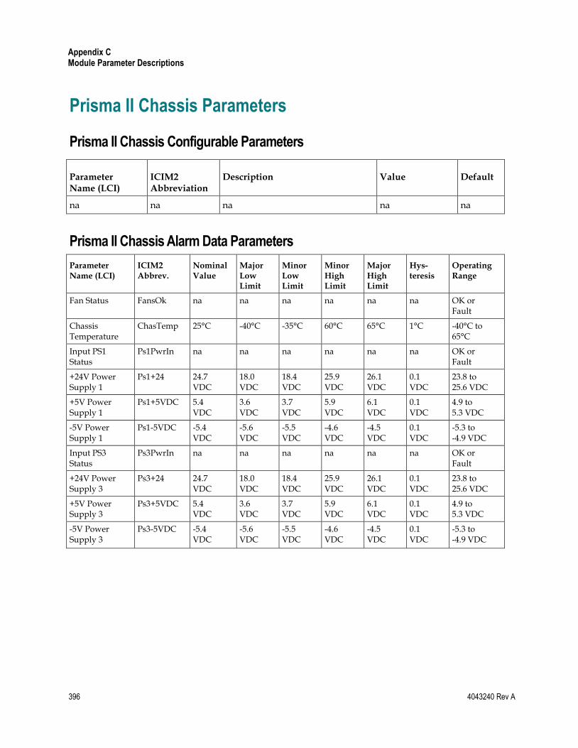
Appendix C Module Parameter Descriptions
396 4043240 Rev A
Prisma II Chassis Parameters
Prisma II Chassis Configurable Parameters
Parameter Name (LCI)
ICIM2 Abbreviation
Description Value Default
na na na na na
Prisma II Chassis Alarm Data Parameters
Parameter Name (LCI)
ICIM2 Abbrev.
Nominal Value
Major Low Limit
Minor Low Limit
Minor High Limit
Major High Limit
Hys- teresis
Operating Range
Fan Status FansOk na na na na na na OK or Fault
Chassis Temperature
ChasTemp 25°C -40°C -35°C 60°C 65°C 1°C -40°C to 65°C
Input PS1 Status
Ps1PwrIn na na na na na na OK or Fault
+24V Power Supply 1
Ps1+24 24.7 VDC
18.0 VDC
18.4 VDC
25.9 VDC
26.1 VDC
0.1 VDC
23.8 to 25.6 VDC
+5V Power Supply 1
Ps1+5VDC 5.4 VDC
3.6 VDC
3.7 VDC
5.9 VDC
6.1 VDC
0.1 VDC
4.9 to 5.3 VDC
-5V Power Supply 1
Ps1-5VDC -5.4 VDC
-5.6 VDC
-5.5 VDC
-4.6 VDC
-4.5 VDC
0.1 VDC
-5.3 to -4.9 VDC
Input PS3 Status
Ps3PwrIn na na na na na na OK or Fault
+24V Power Supply 3
Ps3+24 24.7 VDC
18.0 VDC
18.4 VDC
25.9 VDC
26.1 VDC
0.1 VDC
23.8 to 25.6 VDC
+5V Power Supply 3
Ps3+5VDC 5.4 VDC
3.6 VDC
3.7 VDC
5.9 VDC
6.1 VDC
0.1 VDC
4.9 to 5.3 VDC
-5V Power Supply 3
Ps3-5VDC -5.4 VDC
-5.6 VDC
-5.5 VDC
-4.6 VDC
-4.5 VDC
0.1 VDC
-5.3 to -4.9 VDC

Prisma II Chassis Parameters
4043240 Rev A 397
Prisma II Chassis Operating Status Parameters
Parameter Name (LCI)
ICIM2 Abbreviation
Function Initial Value
Typical Value (Op.)
Power Supply 1 Installed
Ps1Inst 1 if slot 1 PS installed, 0 if not 1 (Inst) 1 (Inst)
+24V Power Supply 1
Ps1+24V measured +24 V DC of slot 1 24.97V 24.97V
+5V Power Supply 1
Ps1+5V measured +5 V DC of slot 1 5.38V 5.38V
-5V Power Supply 1
Ps1-5V measured -5 V DC of slot 1 -5.42V -5.42V
Power Supply 1 Temperature
Ps1Temp internal slot 1 PS temperature 32.7°C 32.7°C
Power Supply 3 Installed
Ps3Inst 1 if slot 3 PS installed, 0 if not 1 (Inst) 1 (Inst)
+24V Power Supply 3
Ps3+24V measured +24 V DC of slot 3 25.03V 25.03V
+5V Power Supply 3
Ps3+5V measured +5 V DC of slot 3 5.38V 5.38V
-5V Power Supply 3
Ps3-5V measured -5 V DC of slot 3 -5.43V -5.43V
Power Supply 3 Temperature
Ps3Temp internal slot 3 PS temperature 28.7°C 28.7°C
+24V Voltage Chas+24V chassis +24 V rail 24.14V 24.14V
+5V Voltage Chas+5V chassis +5 V rail 5.08V 5.08V
-5V Voltage Chas-5V chassis -5 V rail -5.05V -5.05V
Chassis Temperature
ChasTemp fan tray internal temperature 36.0°C 36.0°C
Fans Running FansOn 1 if fans are running, 0 if shut off 1 (ON) 1 (ON)
Note: All monitored values may vary from module to module. The values shown above are examples only.

Appendix C Module Parameter Descriptions
398 4043240 Rev A
Prisma II Chassis Manufacturing Data Parameters
Fan Tray
Parameter Name (LCI)
ICIM2 Abbreviation
Typical Values
Generic Name na Fan Tray
Description na Fan Tray
Software Revision Sw Ver CCB612
Script Version na 9
Serial Number Serial # AALR1RL
Time of Service In Service Hours 26 Hrs
Day Code Date Code J04
Module Type na 5000
na Spec Data (MANDATA) (blank)
Power Supply
Parameter Name (LCI)
ICIM Abbreviation
Typical Values
Generic Name na Power Supply
Description na Power Supply
Software Revision Sw Ver na
Script Version na na
Serial Number Serial # na
Time of Service In Service Hours na
Day Code Date Code na
Module Type na 5000
na Spec Data (MANDATA) (blank)
Note: Some of these values may vary from module to module. The values shown above are examples only.

4043240 Rev A 399
A
ac, AC
alternating current. An electric current that reverses its direction at regularly recurring intervals.
AGC
automatic gain control. A process or means by which gain is automatically adjusted in a specified manner as a function of input level or other specified parameters.
B
binding
A parameter representing the physical or logical objects associated with a trap. C
CAT5
category 5 Ethernet cable.
CDE
common desktop environment.
CLEI
common language equipment identifier. CLEI code is globally unique ten-character intelligent code, assigned by Telcordia, that identifies communications equipment in a concise, uniform feature-oriented language, which describes product type, features, source document and associated drawings and vintages.
CLI
command line interface. A command reference software that allows the user to interact with the operating system by entering commands and optional arguments.
CLLI
common language location identification. A CLLI code is typically an 11-character alphanumeric descriptor used to identify network elements and their locations.
CSV
comma-separated values. A data file format supported by many spreadsheet programs, in
Glossary

Glossary
400 4043240 Rev A
which fields are separated by commas. Also referred to as comma delimited. D
DB-37
37-pin D-sub connector.
dc, DC
direct current. An electric current flowing in one direction only and substantially constant in value.
E
EIA
Electronic Industries Association. A United States association that provides standards for use between manufacturers and purchasers of electronic products.
EMC
electromagnetic compatibility. A measure of equipment tolerance to external electromagnetic fields.
EMT
externally-modulated transmitter.
ESD
electrostatic discharge. Discharge of stored static electricity that can damage electronic equipment and impair electrical circuitry, resulting in complete or intermittent failures.
F
FTTP
fiber-to-the-premises. Fiber optic service to the subscriber's premises. G
GUI
graphical user interface. A program interface that takes advantage of a computer graphics capabilities to make the program visually easier to use.
I
I/O
input/output.
ICIM
intelligent communications interface module.
IP
Internet protocol. A standard that was originally developed by the United States Department

Glossary
4043240 Rev A 401
of Defense to support the internetworking of dissimilar computers across a network. IP is perhaps the most important of the protocols on which the Internet is based. It is the standard that describes software that keeps track of the internetwork addresses for different nodes, routes, and outgoing/incoming messages on a network. Some examples of IP applications include email, chat, and Web browsers.
ISO
International Organization for Standardization. An international body that defines global standards for electronic and other industries.
L
LCD
liquid crystal display. A display medium made of liquid crystal. Liquid crystal's reflectance changes when an electric field is applied. Commonly used in monitors, televisions, cell phones, digital watches, etc.
LED
light-emitting diode. An electronic device that lights up when electricity passes through it. M
MIB
management information base. SNMP collects management information from devices on the network and records the information in a management information base. The MIB information includes device features, data throughput statistics, traffic overloads, and errors.
N
nm
nanometer. One billionth of a meter.
NMS
network management system. A software system designed specifically to monitor a network and to facilitate troubleshooting.
O
OID
object identifier.
OMI
optical modulation index, expressed in decimal or percentage notation. P
PLL
phase lock loop. An electronic servo system controlling an oscillator to maintain a constant phase angle relative to a reference signal.
Glossary
402 4043240 Rev A
polling
In a transmission network system, the active sampling of the status of network devices by a control and monitoring program.
R
RF
radio frequency. The frequency in the portion of the electromagnetic spectrum that is above the audio frequencies and below the infrared frequencies, used in radio transmission systems.
RMA
return material authorization. A form used to return products.
RT
remote terminal. Remote equipment of a supervisory system.
RTC
real time clock.
RX
receive or receiver. S
SBS
stimulated Brillouin scattering. The easiest fiber nonlinearity to trigger. When a powerful lightwave travels through a fiber, it interacts with acoustical vibration modes in the glass. This causes a scattering mechanism to be formed that reflects some of the light back to the source.
semaphore
In programming, a control token (variable or abstract data type) used to restrict access to a resource. The SOUP program uses a semaphore to prevent multiple instances of the SOUP from running and trying to change Prisma II EMS chassis parameters at the same time.
SMC
status monitoring and control. The process by which the operation, configuration, and performance of individual elements in a network or system are monitored and controlled from a central location.
SNMP
simple network management protocol. A protocol that governs network management and the monitoring of network devices and their functions.

Glossary
4043240 Rev A 403
SOUP
software upgrade program. A utility used to update firmware in Prisma II EMS application modules.
T
TEC
thermoelectric cooler. A device used to dissipate heat in electronic assemblies.
Telco
telephone company.
TNCS
Transmission Network Control System. A Cisco application that allows status monitoring and control of all transmission equipment located in headends and hubs plus optical nodes, power supplies, and amplifiers in the outside plant. TNCS provides access to and information on the entire network in an easy to understand, topology driven, graphical user display.
trap
An unsolicited message sent by a network device to notify a network or element management system of an alarm or other condition that requires administrative attention.
TX
transmit or transmitter.


4043240 Rev A 405
A
About Traps • 254 ac, AC • 399 Accessing the Module Detail Information • 152 Active and Inactive Flash • 301 AGC • 399 ALARM IN and OUT Connections • 66 Alarm Severity Mappings • 241 Alarm Threshold Menus • 139 Alarm Threshold Modification • 293 Alarm Troubleshooting • 353 ALARMS IN Connector • 67 ALARMS OUT Connector • 67
B
Back Panel Connectors • 52 Back Plane Bus Connectors • 44 Before You Begin • 54 binding • 399
C
Cable Requirements • 143 CAT5 • 399 CDE • 399 Chassis Back Plane Bus • 43 Chassis Configuration • 39 Chassis Dimensions • 59 Chassis Fan Filter • 69 Chassis Front Panel Features • 42 Chassis Troubleshooting • 352 Chassis Wiring and Fusing • 6, 55 Chassis-to-Chassis ICIM Connections • 3 Chassis-to-Chassis ICIM2 Activation • 64 ChasTemp Alarm • 355 ChasTemp Alarm Parameters • 355 Checking Alarms using the ICIM • 136 Checking Manufacturing Data using LCI • 158 Checking the Module Alarms using LCI • 154 Checking the Operating Status • 153 Cleaning Optical Connectors • 81, 365 Clearing the Event Log • 186
CLEI • 399 CLI • 399 CLI Parameters • 90 CLLI • 399 Computer Requirements • 143 Concepts • 301 Concurrency • 302 CONFIG Menus • 135 Configuring a Module using the ICIM • 135 Configuring for Remote Network Access • 113 Configuring IPsec on Solaris • 344 Configuring IPsec on the ICIM • 318 Configuring IPsec on Windows • 321 Connecting Optical Cables • 83, 367 Connecting RF Cables • 84 Connecting the ICIM to Additional Chassis • 62 Connecting Your Computer to the Chassis • 148 Connector Interface Panel • 60 Connector Interface Panel Illustration • 60 CSV • 399 Current Alarm Table • 242 Current Alarms • 389 Customer Information • 369
D
DB-37 • 400 DC Power Inlet Illustration • 8 dc, DC • 400 Delay in the Discovery Process • 295 Downloading and Viewing the Event Log
Remotely • 191
E
EIA • 400 Electrical Input Voltages • 47 Electrical Power Connections • 6, 71 EMC • 400 EMT • 400 Enhanced Trap Alarms • 272 Enhanced Trap Binding Information • 268 Enhanced Trap Events • 275 Equipment Configuration • 85
Index

Index
406 4043240 Rev A
ESD • 400 Event Action IDs • 181 Event Log • 179 Event Log Fields • 180 Event Log File Management • 209 Event Log-Related Traps • 189 Expired Password or Inactive Password
Messages • 107, 131 External Alarms Connections • 66
F
Fan Tray • 68 Fan Tray ALARMS Menus • 118 Fan Tray Configuration • 45 Fan Tray Front Panel Features • 46 Fan Tray Illustration (Top View) • 46 Fan Tray Installation • 45 Fan Tray Menu Structure • 116 Fan Tray MFG. DATA Menus • 120 Fan Tray STATUS Menus • 117 FansOk Alarm • 354 FansOk Alarm Parameters • 354 Firmware Updates • 312 Firmware Upgrade Process • 307 Frequently Asked Questions • 296 From */* MODULE • 379 From CLI • 372 From ICIM • 373 From TERMINAL • 382 Front-Access Chassis • 41 FTP Server • 311 FTP Settings • 309 FTTP • 400
G
GUI • 400
H
Hardware Installation • 53 How do Enhanced Traps differ from other trap
types? • 297 How do I configure trap destination? • 296 HyperTerminal Session Setup • 86
I
I/O • 400 ICIM • 400 ICIM as Proxy for Module Information • 295 ICIM Data • 385 ICIM IN and ICIM OUT Cables • 5, 64
ICIM IN and ICIM OUT Connectors • 3, 64 ICIM Menu • 111 ICIM MIB • 195 ICIM Operation • 101 ICIM Password • 106 ICIM Password (Keypad Interface) • 130 ICIM2 • 37 ICIM2 Block Diagram • 45 ICIM2 Front Panel Features • 51, 104 ICIM2 Illustration (Front Panel) • 51, 103 ICIM2 Keypad • 105 ICIM2 LCD • 104 Insert Module Table • 250 Installing LCI • 144 Installing the ICIM2 • 76 Installing the Module in the Chassis • 78 Installing the Power Supplies • 71 Installing the SOUP • 300 Integration with an NMS (Optional) • 302 Introduction • 33, 160, 180, 194 IP • 400 IPsec Overview • 316 IPsec Packets • 316 ISO • 401
K
Key Exchange • 316
L
Launching Standalone (Windows Only) • 303 LCD • 401 LCI Introduction • 142 LCI Module Tree • 151 LCI Operation • 141 LED • 401 Login • 90 Login Settings • 97
M
MAIN Menu • 111 Maintenance • 351 Maintenance and Troubleshooting • 349 Maintenance Record • 351 Master-Slave Illustration • 67 Master-Slave Operation • 66 MIB • 401 Modifying Module Alarm Limits using LCI •
156 Module Alarm Table • 235 Module Alarms • 390

Index
4043240 Rev A 407
Module Back Panel • 52 Module Control Table • 247 Module Controls • 391 Module Data • 388 Module MIB • 226 Module Monitor Table • 244 Module Monitors • 392 Module Removal and Enhanced Traps • 295 Module Table • 227 Module Tree • 151 Mounting the Chassis in a Rack • 58
N
nm • 401 NMS • 401
O
OID • 401 OMI • 401 Operating Environment • 55 Operating the ICIM2 • 103 Overview • 384
P
Password Protection System • 106, 130 Platform Configuration • 102 PLL • 401 polling • 402 Power and Communications Connector • 52 Power Inlets • 47 Power Supply 1 ALARMS Menus • 123 Power Supply 1 Menu Structure • 121 Power Supply 1 MFG. DATA Menus • 125 Power Supply 1 STATUS Menus • 122 Power Supply 3 ALARMS Menus • 128 Power Supply 3 Menu Structure • 126 Power Supply 3 MFG. DATA Menus • 130 Power Supply 3 STATUS Menus • 127 Power Supply Block Diagram • 48 Power Supply Cooling Fans • 75 Power Supply Front Panel Features • 49 Power Supply Front Panel Illustrations • 49 Prisma II Application Modules • 38 Prisma II Chassis • 39 Prisma II Chassis Alarm Data Parameters • 396 Prisma II Chassis Configurable Parameters • 396 Prisma II Chassis Manufacturing Data
Parameters • 398 Prisma II Chassis Operating Status Parameters •
397
Prisma II Chassis Parameters • 396 Prisma II Enterprise MIBs • 194 Prisma II Fan Tray • 37, 45 Prisma II ICIM2 • 50 Prisma II MAIN Menu and ICIM Menu
Structure • 110 Prisma II Platform Components • 36 Prisma II Platform Description • 36 Prisma II Power Supplies • 37, 43 Prisma II Power Supply • 47 Prisma II Traps • 254 Ps1+24 Alarm • 358 Ps1+24 Alarm Parameters • 358 Ps1+5VDC Alarm • 359 Ps1+5VDC Alarm Parameters • 359 Ps1-5VDC Alarm • 360 PS1-5VDC Alarm Parameters • 360 Ps1PwrIn Alarm • 357 Ps1PwrIn Alarm Parameters • 357 Ps3+24 Alarm • 362 Ps3+24 Alarm Parameters • 362 Ps3+5VDC Alarm • 363 Ps3+5VDC Alarm Parameters • 363 Ps3-5VDC Alarm • 364 PS3-5VDC Alarm Parameters • 364 Ps3PwrIn Alarm • 361 Ps3PwrIn Alarm Parameters • 361
Q
Quick Start Guide • 1
R
Rack Location Requirements • 57 Recommended Equipment • 81, 365 References • 348 Related Publications • 35 Release Files • 301 Remote Firmware Download Feature • 299 Remote Reboot of ICIM and Modules • 253 Remove Module Table • 251 Replacing the Default Admin Account • 163 Required Equipment and Tools • 54 RF • 402 RMA • 402 RT • 402 RTC • 402 RX • 402
S
Sample Module Details Window • 152

Index
408 4043240 Rev A
SBS • 402 semaphore • 402 Setting Event Log Filter Parameters • 187 Setting Up IPsec • 315 Site Requirements • 55 SMC • 402 SNMP • 402 SNMP Management • 193 SNMP Parameters • 96 SNMP Settings • 310 SNTP Time Synchronization • 213 Solaris Configuration Files • 344 SOUP • 403 SOUP Main Screen • 305 Space Requirements • 71 Starting LCI Software • 149 Step 1
Install the Chassis in a Rack • 2 Step 10
Perform Chassis-to-Chassis ICIM Activation (Optional) • 25
Step 11 Make Changes to Traps and Enterprise MIBs
• 26 Step 12
Make Physical Connections to Modules • 28 Step 13
Verify System Release and Module Firmware Versions • 29
Step 14 Install and Use the Firmware Update (SOUP)
Utility (Optional) • 30 Step 2
Make Chassis-to-Chassis ICIM Connections • 3
Step 3 Make Electrical Power Connections • 6
Step 4 Install the ICIM • 13
Step 5 Set Network Parameters from the Command
Line Interface (CLI) • 14 Step 6
Connect the ICIM to the Network • 18 Step 7
Install Modules in the Chassis • 20 Step 8
Set Additional Parameters via CLI (Optional) • 22
Step 9
Set and Verify SNMP Community Strings • 23
Suggested Actions • 354, 355, 357, 358, 359, 360, 361, 362, 363, 364
System Behavior • 295 System Information • 393 System Requirements • 143
T
TEC • 403 Telco • 403 Telnet Session • 94 The Chassis and the ICIM2 • 301 Tips for Optimal Fiber Optic Connector
Performance • 81, 365 TNCS • 403 To Access the IPsec Management Console • 321 To Access the Password Menu • 106, 131 To Add or Delete an IPsec Peer • 319 To Adjust the ICIM2 LCD Contrast • 105 To Change the Chassis ID Number • 4, 63 To Change the User Password • 108, 133 To Check Alarm Thresholds • 139 To Check Alarms • 117, 122, 127 To Check Alarms using LCI • 154 To Check Alarms using the ICIM • 136 To Check Fan Tray Manufacturing Data • 119 To Check Manufacturing Data using LCI • 158 To Check Operating Status • 116, 121, 126 To Check Power Supply 1 Manufacturing Data •
124 To Check Power Supply 3 Manufacturing Data •
129 To Check the Operating Status using LCI • 153 To Clean Optical Connectors • 82, 366 To Configure IPsec on Solaris • 348 To Configure Parameters using the ICIM • 135 To Configure the ICIM2 for SNMP • 113 To Configure Trap Destination • 256 To Connect Optical Cables • 83, 367 To Connect RF Cables • 84 To Connect the Computer to a Prisma II Chassis
• 148 To Create a New Filter Action • 330 To Create a New IP List • 327 To Create a New IPsec Policy • 335 To Disable the User Password using ICIM • 109,
134 To Display IPsec Information • 320 To Enable and Disable IPsec • 318

Index
4043240 Rev A 409
To Enter the User Password • 107, 132 To Install the AC Power Cord • 11, 73 To Install the Chassis in a Rack • 2, 58 To Install the DC Power Cord • 10, 73 To Install the ICIM2 • 13, 76 To Install the LCI Software • 144 To Install the Module • 20, 78 To Install the Power Supply in the Chassis • 11,
74 To Install the SOUP on Windows • 300 To Log In • 98 To Log Out • 99 To Make ICIM IN and ICIM OUT Cable
Connections • 3, 62 To Modify Alarm Limits using LCI • 156 To Monitor the Power Supply • 75 To Remove Chassis Fan Filter • 70 To Remove the Fan Tray • 68 To Restart the ICIM2 • 115 To Set Additional Users for ICIM Access • 22,
91 To Set Adjustable Alarm Thresholds using the
ICIM • 138 To Set and Verify SNMP Community Strings •
92 To Set the Clock • 91 To Set Up a HyperTerminal Serial Port Session •
86 To Set Up a Telnet CLI Session • 18, 94 To Start LCI Software • 149 To Uninstall the SOUP on Windows • 300 To View Alarms • 138 trap • 403 Trap Handling • 216 Trap Logging Auxiliaries • 220 Trap Logging Table • 221 Trap Receiving Configuration • 255 Trap Recv Table • 216 Trap Types • 257 Troubleshooting • 352 TX • 403 Typical Chassis Block Diagram • 40
U
Unpacking and Inspecting the Chassis • 54 Unused Slots • 57 Usage • 303 User Lockout • 174 User Management • 159, 394 Using ICIM2 with Power Supply 1 • 121
Using ICIM2 with Power Supply 3 • 126 Using ICIM2 with the Fan Tray • 116 Using the ICIM Web Interface • 97
V
Viewing the Event Log • 184
W
Warning Labels • xxvii What is the Trap Logging Table? • 298 When do traps associated with module insertion,
removal, and alarms occur? • 297 Where can I find trap definitions? • 298 Why do the same alarm values represent
different conditions? • 296 Working With User Accounts • 167

5030 Sugarloaf Parkway, Box 465447 Lawrenceville, GA 30042
678 277-1120 800 722-2009
This document includes various trademarks of Cisco Systems, Inc. Please see the Notices section of this document for a list of Cisco Systems, Inc. trademarks used in this document.
Product and service availability are subject to change without notice.
© 2012 Cisco and/or its affiliates. All rights reserved. August 2012 Printed in United States of America
Part Number 4043240 Rev A
Recommended