Hita
ch
i Cir
cu
it Bre
ak
ers
& M
inia
ture
Cir
cu
it Bre
ak
ers
:Philippines
Hitachi Asia Ltd. (Philippines Branch)
25th Floor, Pacific Star Building, Cor. Makati & Sen. Gil.
Puyat Ave., Makati, Metro Manila
TEL :<63>(2)819-7528, -7529
FAX:<63>(2)819-7539
:Thailand
Hitachi Asia (Thailand) Co., Ltd.
18th Floor, Ramaland Building, 952 Rama IV Road
Bangrak, Bangkok 10500
TEL :<66>(2)632-9292
FAX:<66>(2)632-9299
:China
Hitachi East Asia Ltd.
4th Floor, North Tower
World Finance Centre, Harbour City
Canton Road, Tsim Sha Tsui, Kowloon
Hong Kong
TEL :<852>2735-9218
FAX:<852>2375-3192
Hitachi China Ltd. (Beijing Office)
Room 1412, Beijing Fortune Building
5 Dong San Huan BeiLu
Chao Yang District, Beijing 100004
TEL :<86>(10)6590-8851, -8852, -8853, -8854
FAX:<86>(10)6590-8850
Hitachi (Shanghai) Trading Co., Ltd.
18th Floor, Rui Jin Building,
No.205, Maoming Road(S)
Shanghai, 200030
TEL :<86>(21)6472-1002
FAX:<86>(21)6415-8272
Taiwan Hitachi Asia Pacific Co., Ltd.
3rd Floor, Hung Kuo Building No.167
Tun-Hwa North Road, Taipei (105) , Taiwan
TEL :<886>(2)2718-3666
FAX:<886>(2)2718-8180
Information in this brochure is subject to change without notice.
For further information, please contact your nearest sales representative.
Printed in Japan (H) SI-E123 (0709)
http://www.hitachi-ies.co.jp/english/index.htm
:Headquarters
AKS Building, 3, Kanda Neribei-cho,
Chiyoda-ku, Tokyo, 101-0022, Japan
TEL:<81>(3)4345-6000
FAX:<81>(3)4345-6914
:Singapore
Hitachi Asia Ltd.
Power & Industrial Systems Group
24 Jurong Port Poad, #03-05 Cwt Distripark,
Office Block, Singapore, 619097
TEL:<65>(6305)7400
FAX:<65>(6305)7401
:Vietnam
Hitachi Asia Ltd.(Ho Chi Minh City Office)
7th Floor, The Landmark, 5B Ton Duc Thang
Street District 1, Ho Chi Minh City
TEL :<84>(8)829-9725
FAX:<84>(8)829-9729
(Ha Noi Office)
Sun Red River Bldg, 6th Floor,
23 Phan Chu Trinh Street
Hoan Kiem District Hanoi
TEL :<84>(4)933-3123
FAX:<84>(4)933-3125
: India
Hitachi India Trading Pvt. Ltd.
Hindustan Times House (10th Floor)
18-20, Kasturba Gandhi Marg., New Delhi, 110001
TEL:<91>(11)331-5635, 371-2817, -3953, -3958
FAX:<91>(11)331-3742
: Indonesia
Hitachi Asia Ltd. (Jakarta Office)
Mid Plaza 1, 10th Floor, J.I. Jend.
Sudirman Kav. 10-11, Jakarta 10220
TEL:<62>(21)574-4313
FAX:<62>(21)574-4312
:Malaysia
Hitachi Asia (Malaysia) Sdn. Bhd.
Suite 17.3, Level 17, Menara IMC (Letter Box No.5)
No. 8 Jalan Sultan Ismail, 50250, Kuala Lumpur
TEL:<60>(3)201-8751
FAX:<60>(3)201-8757, -8758
Circuit Breakers & Miniature Circuit Breakers
Hitachi Industrial Equipment Systems Co., Ltd.

1
Hitachi Circuit Breakers and Miniature Circuit Breakers are
designed for circuit protection of low-voltage distribution
systems. They are suitable for application as main breakers and
for protection of branch and feeder circuits and connected
apparatus. These breakers provide overload protection for
conductors and short-circuit protection for all circuit elements
appLications
contents
Applications ..........................................................................................................................................1
Fuse-Free Breakers
New Line-up Series (Features) ........................................................................................................................... 2
Classifi cation and Composition ......................................................................................................................... 4
Composition in terms of Interrupting Capacity ............................................................................................... 5
Ratings and Specifi cations ................................................................................................................................. 6
Construction ..................................................................................................................................................... 15
Characteristics .................................................................................................................................................. 19
Caution..............................................................................................................................................................20
Selection ........................................................................................................................................................... 21
Accessories ........................................................................................................................................................ 25
Dimensions .......................................................................................................................................................39
Earth Leakage Breakers and Earth Leakage Relays
Classifi cation and Composition .......................................................................................................................67
Ratings and Specifi cations ...............................................................................................................................68
Construction ..................................................................................................................................................... 72
Application of Earth Leakage Relays .............................................................................................................. 75
Dimensions ....................................................................................................................................................... 76
Earth Leakage Breakers for Welders ............................................................................................................106
Miniature Circuit Breakers
Features...........................................................................................................................................................108
Specifi cations .................................................................................................................................................. 109
Characteristic curve and Compensation curve............................................................................................. 110
Residual Circuit Breakers
Features............................................................................................................................................................111
Specifi cations .................................................................................................................................................. 112
Air Circuit Breakers (AKN, AKS, AKH series)
Ordering ......................................................................................................................................................... 114
Ratings ............................................................................................................................................................ 120
Dimensions ..................................................................................................................................................... 142
such as conductors, motors, and starters.
They are designed for use in switchboard, control centers,
panel boards, combination starters, and separate individual
enclosures. In these various enclosures, they are applicable to
the requirements of lighting, distribution, and other power
circuits.
2
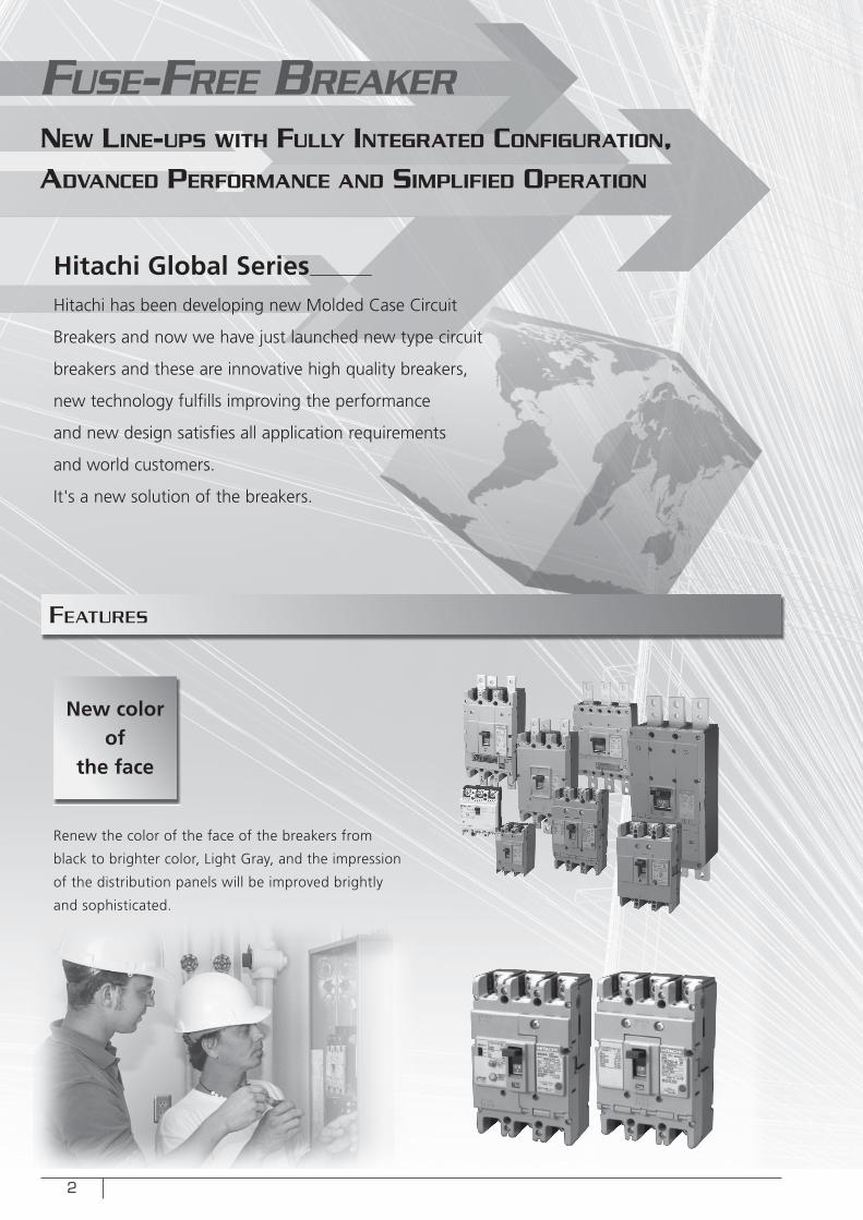
Hitachi Global SeriesHitachi has been developing new Molded Case Circuit
Breakers and now we have just launched new type circuit
breakers and these are innovative high quality breakers,
new technology fulfi lls improving the performance
and new design satisfi es all application requirements
and world customers.
It's a new solution of the breakers.
Renew the color of the face of the breakers from
black to brighter color, Light Gray, and the impression
of the distribution panels will be improved brightly
and sophisticated.
FUSE-FREE BREAKER
NEW LINE-UPS WITH FULLY INTEGRATED CONFIGURATION, ADVANCED PERFORMANCE AND SIMPLIFIED OPERATION
featURes
New color of
the face
3
Easy to install the
accessories and
easy to change the
specifi cations
Dimensions are unifi ed for the economical and standard types,
contributing to total cost reduction of the control panel.
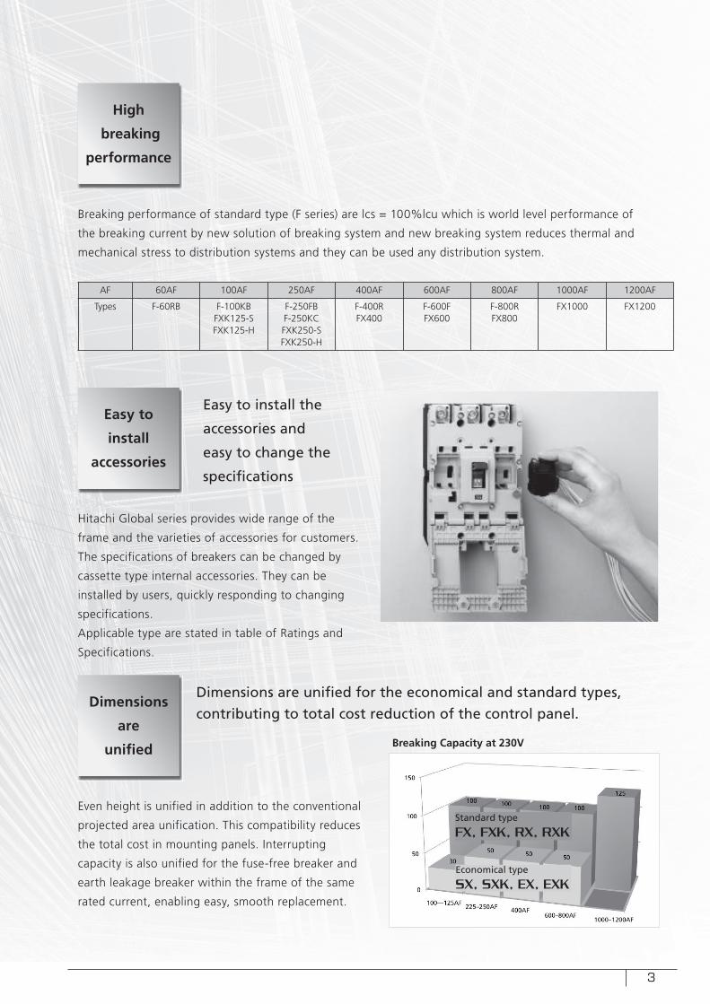
Breaking performance of standard type (F series) are lcs = 100%lcu which is world level performance of
the breaking current by new solution of breaking system and new breaking system reduces thermal and
mechanical stress to distribution systems and they can be used any distribution system.
Hitachi Global series provides wide range of the
frame and the varieties of accessories for customers.
The specifications of breakers can be changed by
cassette type internal accessories. They can be
installed by users, quickly responding to changing
specifications.
Applicable type are stated in table of Ratings and
Specifications.
Even height is unified in addition to the conventional
projected area unification. This compatibility reduces
the total cost in mounting panels. Interrupting
capacity is also unified for the fuse-free breaker and
earth leakage breaker within the frame of the same
rated current, enabling easy, smooth replacement.
AF 60AF 100AF 250AF 400AF 600AF 800AF 1000AF 1200AF
Types F-60RB F-100KBFXK125-SFXK125-H
F-250FBF-250KCFXK250-SFXK250-H
F-400RFX400
F-600FFX600
F-800RFX800
FX1000 FX1200
Standard type
FX, FXK, RX, RXK
Economical type
SX, SXK, EX, EXK
Breaking Capacity at 230V
High
breaking
performance
Easy to
install
accessories
Dimensions
are
unifi ed
4
cLassification and coMposition
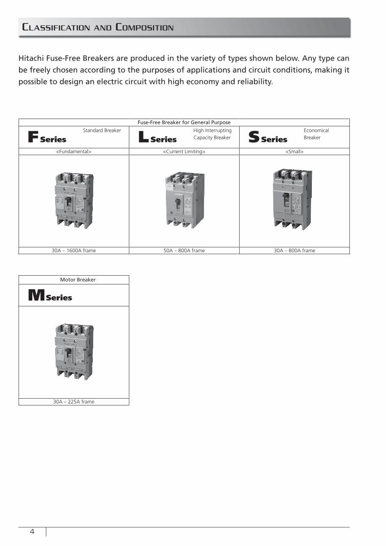
Hitachi Fuse-Free Breakers are produced in the variety of types shown below. Any type can
be freely chosen according to the purposes of applications and circuit conditions, making it
possible to design an electric circuit with high economy and reliability.
Fuse-Free Breaker for General Purpose
FSeries LSeries SSeries<Fundamental> <Current Limiting> <Small>
30A – 1600A frame 50A – 800A frame 30A – 800A frame
Motor Breaker
MSeries
30A – 225A frame
Standard Breaker High Interrupting Capacity Breaker
Economical Breaker
5
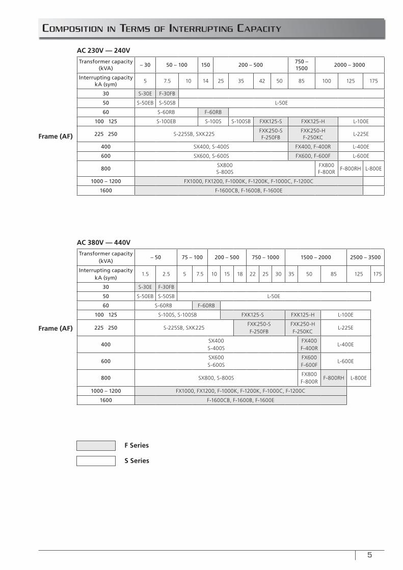
coMposition in teRMs of inteRRUpting capacitY
Transformer capacity (kVA)
– 30 50 – 100 150 200 – 500750 – 1500
2000 – 3000
Interrupting capacity kA (sym)
5 7.5 10 14 25 35 42 50 85 100 125 175
30 S-30E F-30FB
50 S-50EB S-50SB L-50E
60 S-60RB F-60RB
100 125 S-100EB S-100S S-100SB FXK125-S FXK125-H L-100E
225 250 S-225SB, SXK225FXK250-SF-250FB
FXK250-HF-250KC
L-225E
400 SX400, S-400S FX400, F-400R L-400E
600 SX600, S-600S FX600, F-600F L-600E
800SX800S-800S
FX800F-800R
F-800RH L-800E
1000 – 1200 FX1000, FX1200, F-1000K, F-1200K, F-1000C, F-1200C
1600 F-1600CB, F-1600B, F-1600E
Transformer capacity (kVA)
– 50 75 – 100 200 – 500 750 – 1000 1500 – 2000 2500 – 3500
Interrupting capacity kA (sym)
1.5 2.5 5 7.5 10 15 18 22 25 30 35 50 85 125 175
30 S-30E F-30FB
50 S-50EB S-50SB L-50E
60 S-60RB F-60RB
100 125 S-100S, S-100SB FXK125-S FXK125-H L-100E
225 250 S-225SB, SXK225FXK250-SF-250FB
FXK250-HF-250KC
L-225E
400SX400S-400S
FX400F-400R
L-400E
600SX600S-600S
FX600F-600F
L-600E
800 SX800, S-800SFX800F-800R
F-800RH L-800E
1000 – 1200 FX1000, FX1200, F-1000K, F-1200K, F-1000C, F-1200C
1600 F-1600CB, F-1600B, F-1600E
AC 230V — 240V
AC 380V — 440V
Frame (AF)
Frame (AF)
F Series
S Series
6
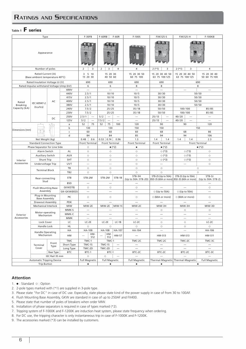
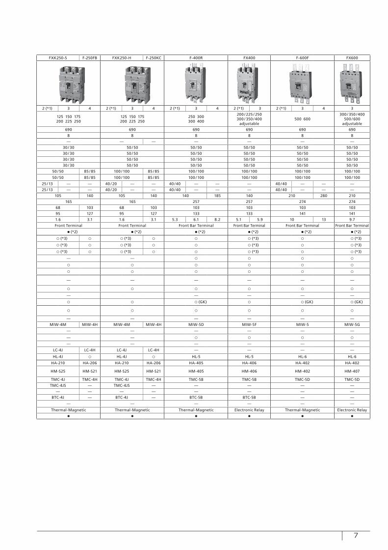
Ratings and specifications
Type F-30FB F-60RB F-60R F-100S FXK125-S FXK125-H F-100KB FXK250-S F-250FB FXK250-H F-250KC F-400R FX400 F-600F FX600
Appearance
Number of poles 2 3 2 3 4 4 2 (*1) 3 2 (*1) 3 4 2 (*1) 3 4 2 (*1) 3 4 2 (*1) 3 4 2 (*1) 3 2 (*1) 3 4 3
Rated Current (A)(Base ambient temperature 40ºC)
3 5 1015 20 30
15 20 3040 50 60
15 20 30 5060 75 100
15 20 30 40 5063 75 100 125
15 20 30 40 5063 75 100 125
15 20 30 4050 60 75 100
125 150 175200 225 250
125 150 175200 225 250
250 300300 400
200 / 225 / 250300 / 350 /400
adjustable500 600
300 / 350 /400500 / 600
adjustable
Rated Insulation Voltage Ui (V) 690 690 690 690 690 690 690 690 690 690 690
Rated Impulse withstand Voltage Uimp (kV) 6 6 8 8 8 8 8 8 8 8 8
Rated Breaking
Capacity (kA)
IEC 60947-2
(Icu/Ics)
AC
690V — — — — — — — — — — — — —
440V 2.5 / 1 10 / 10 10 / 5 30 / 30 50 / 50 30 / 30 50 / 50 50 / 50 50 / 50 50 / 50 50 / 50
415V 2.5 / 1 10 / 10 10 / 5 30 / 30 50 / 50 30 / 30 50 / 50 50 / 50 50 / 50 50 / 50 50 / 50
400V 2.5 / 1 10 / 10 10 / 5 30 / 30 50 / 50 30 / 30 50 / 50 50 / 50 50 / 50 50 / 50 50 / 50
380V 2.5 / 1 10 / 10 10 / 5 30 / 30 50 / 50 30 / 30 50 / 50 50 / 50 50 / 50 50 / 50 50 / 50
240V 7.5 / 2 25 / 25 35 / 18 50 / 50 100 / 100 85 / 85 50 / 50 85 / 85 100 / 100 85 / 85 100 / 100 100 / 100 100 / 100 100 / 100
230V 7.5 / 2 25 / 25 35 / 18 50 / 50 100 / 100 85 / 85 50 / 50 85 / 85 100 / 100 85 / 85 100 / 100 100 / 100 100 / 100 100 / 100
DC250V 2.5 / 1 — 5 / 2 — — — 25 / 13 — 40 / 20 — — 25 / 13 — — 40 / 20 — — 40 /40 — — — 40 /40 — — —
125V 5 / 2 — 7.5 / 2 — — — 25 / 13 — 40 / 20 — — 25 / 13 — — 40 / 20 — — 40 /40 — — — 40 /40 — — —
Dimensions (mm)
a 52 75 52 75 100 120 90 90 120 105 140 105 140 140 185 140 210 280 210
b 130 130 150 150 150 165 165 257 257 274 274
c 60 60 60 68 68 86 68 103 68 103 103 103 103 103
d 84 84 85 94 94 106 95 127 95 127 133 133 141 141
Net Weight (kg) 0.48 0.6 0.53 0.74 0.96 1.3 1.4 1.4 1.4 1.4 2.3 1.6 3.1 1.6 3.1 5.3 6.1 8.2 5.1 5.9 10 13 9.7
Standard Connection Type Front Terminal Front Terminal Front Terminal Front Terminal Front Terminal Front Terminal Front Terminal Front Bar Terminal Front Bar Terminal Front Bar Terminal Front Bar Terminal
Phase Separator for Line Side ○ ● (*2) ● ● (*2) ● (*2) ● (*2) ● (*2) ● (*2) ● (*2) ● (*2) ● (*2)
Interior Accessories
Alarm Switch AL ○ ○ ○ ○ (*3) ○ (*3) ○ ○ (*3) ○ ○ (*3) ○ ○ ○ (*3) ○ ○ (*3)
Auxiliary Switch AUX ○ ○ ○ ○ (*3) ○ (*3) ○ ○ (*3) ○ ○ (*3) ○ ○ ○ (*3) ○ ○ (*3)
Shunt Trip SHT ○ ○ ○ ○ (*3) ○ (*3) ○ ○ (*3) ○ ○ (*3) ○ ○ ○ (*3) ○ ○ (*3)
Undervoltage Trip UVT — — ○ — — ○ — — ○ ○ ○ ○
Terminal BlockTB ○ ○ ○ ○ ○ ○ ○ ○ ○ ○ ○
TB2 ○ ○ ○ ○ ○ ○ ○ ○ ○ ○ ○
Exterior Accessories
Rear-connecting Stud
STB STB-2M STB-2M STB-1B STB-3H(Up to 50A : STB-2D)
STB-2S (Up to 50A)BSD-3S (60A or more)
STB-2S (Up to 50A)BSD-3S (60A or more)
STB-3J(Up to 50A : STB-2) — — — — — —
BSD — — — — ○ ○ ○ ○ ○ ○
Flush Mounting Base Assembly
GKW(STB) ○ ○ ○ — — ○ — — — — —
GK•GKW(BSD) — — — ○ (Up to 50A) ○ (Up to 50A) — ○ ○ ○ (GK) ○ ○ (GK) ○ (GK)
Plug-in Mounting Base Assembly PK ○ ○ ○ ○ (60A or more) ○ (60A or more) ○ ○ ○ ○ ○ ○ ○
Drawout Assembly PDK — — — — — — — — — — — —
Mechanical Interlock MIW MIW-2E MIW-2E MIW-1C MIW-2C MIW-3H MIW-3H MIW-3D MIW-4M MIW-4H MIW-4M MIW-4H MIW-5D MIW-5F MIW-5 MIW-5G
Motor-operating Mechanism
MMK-S — — — ○ ○ ○ — — — — — —
MMK-C — — — — — — — — ○ ○ ○ ○
MMK — — — — — — — — — — — —
Lock Cover LC LC-2E LC-2E LC-1B LC-2C ○ ○ LC-2C LC-4J LC-4H LC-4J LC-4H — — — —
Handle Lock HL ○ ○ ○ ○ ○ ○ HL-4J ○ HL-4J ○ HL-5 HL-5 HL-6 HL-6
Handle Operating Mechanism
HA HA-108 HA-108 HA-107 HA-104 — — HA-106 HA-210 HA-206 HA-210 HA-206 HA-405 HA-406 HA-402 HA-402
HM — HM-S12 — HM-
S12 HM-57 — HM-S13 HM-S13 HM-S11 HM-S25 HM-S21 HM-S25 HM-S21 HM-405 HM-406 HM-402 HM-407
Terminal Cover
Front Type
TMC TMC-1 TMC-1 TMC-2C TMC-2C TMC-2C TMC-3C TMC-4J TMC-4H TMC-4J TMC-4H TMC-5B TMC-5B TMC-5D TMC-5D
Short Type TMC-1S TMC-1S — — — — — TMC-4JS — TMC-4JS — — — — —
Long Type TMC-2D TMC-2D — — — — — — — — — — — — —
Rear Type BTC BTC-1 BTC-1 BTC-2C BTC-2C BTC-2C BTC-3C BTC-4J — BTC-4J — BTC-5B BTC-5B — —
IEC Rail 35 mm ○ ○ — — — — — — — — — — —
Automatic Tripping Device Full Magnetic Full Magnetic Full Magnetic Thermal-Magnetic Thermal-Magnetic Full Magnetic Thermal-Magnetic Thermal-Magnetic Thermal-Magnetic Electronic Relay Thermal-Magnetic Electronic Relay
Trip Button ● ● ● ● ● ● ● ● ● ● ●
a
b
dc
Table 1 F series
Attention1. ● : Standard ○ : Option2. 2-pole types marked with (*1) are supplied in 3-pole type. 3. Please state "For DC" in case of DC use. Especially, state please state kind of the power supply in case of from 30 to 100AF.4. Flush Mounting Base Assembly, GKW are standard in case of up to 250AF and FX400.5. Please state that number of poles of breakers when order MIW.6. Installation of phase separators is required in case of types marked (*2).7. Tripping system of F-1000K and F-1200K are induction heat system, please state frequency when ordering.8. For DC use, the tripping character is only instantaneous trip in case of F-1000K and F-1200K.9. The accessories marked (*3) can be installed by customers.
7
Type F-30FB F-60RB F-60R F-100S FXK125-S FXK125-H F-100KB FXK250-S F-250FB FXK250-H F-250KC F-400R FX400 F-600F FX600
Appearance
Number of poles 2 3 2 3 4 4 2 (*1) 3 2 (*1) 3 4 2 (*1) 3 4 2 (*1) 3 4 2 (*1) 3 4 2 (*1) 3 2 (*1) 3 4 3
Rated Current (A)(Base ambient temperature 40ºC)
3 5 1015 20 30
15 20 3040 50 60
15 20 30 5060 75 100
15 20 30 40 50 63 75 100 125
15 20 30 40 50 63 75 100 125
15 20 30 40 50 60 75 100
125 150 175 200 225 250
125 150 175 200 225 250
250 300300 400
200 / 225 / 250300 / 350 /400
adjustable500 600
300 / 350 /400500 / 600
adjustable
Rated Insulation Voltage Ui (V) 690 690 690 690 690 690 690 690 690 690 690
Rated Impulse withstand Voltage Uimp (kV) 6 6 8 8 8 8 8 8 8 8 8
Rated Breaking
Capacity (kA)
IEC 60947-2
(Icu/Ics)
AC
690V — — — — — — — — — — — — —
440V 2.5 / 1 10 / 10 10 / 5 30 / 30 50 / 50 30 / 30 50 / 50 50 / 50 50 / 50 50 / 50 50 / 50
415V 2.5 / 1 10 / 10 10 / 5 30 / 30 50 / 50 30 / 30 50 / 50 50 / 50 50 / 50 50 / 50 50 / 50
400V 2.5 / 1 10 / 10 10 / 5 30 / 30 50 / 50 30 / 30 50 / 50 50 / 50 50 / 50 50 / 50 50 / 50
380V 2.5 / 1 10 / 10 10 / 5 30 / 30 50 / 50 30 / 30 50 / 50 50 / 50 50 / 50 50 / 50 50 / 50
240V 7.5 / 2 25 / 25 35 / 18 50 / 50 100 / 100 85 / 85 50 / 50 85 / 85 100 / 100 85 / 85 100 / 100 100 / 100 100 / 100 100 / 100
230V 7.5 / 2 25 / 25 35 / 18 50 / 50 100 / 100 85 / 85 50 / 50 85 / 85 100 / 100 85 / 85 100 / 100 100 / 100 100 / 100 100 / 100
DC250V 2.5 / 1 — 5 / 2 — — — 25 / 13 — 40 / 20 — — 25 / 13 — — 40 / 20 — — 40 /40 — — — 40 /40 — — —
125V 5 / 2 — 7.5 / 2 — — — 25 / 13 — 40 / 20 — — 25 / 13 — — 40 / 20 — — 40 /40 — — — 40 /40 — — —
Dimensions (mm)
a 52 75 52 75 100 120 90 90 120 105 140 105 140 140 185 140 210 280 210
b 130 130 150 150 150 165 165 257 257 274 274
c 60 60 60 68 68 86 68 103 68 103 103 103 103 103
d 84 84 85 94 94 106 95 127 95 127 133 133 141 141
Net Weight (kg) 0.48 0.6 0.53 0.74 0.96 1.3 1.4 1.4 1.4 1.4 2.3 1.6 3.1 1.6 3.1 5.3 6.1 8.2 5.1 5.9 10 13 9.7
Standard Connection Type Front Terminal Front Terminal Front Terminal Front Terminal Front Terminal Front Terminal Front Terminal Front Bar Terminal Front Bar Terminal Front Bar Terminal Front Bar Terminal
Phase Separator for Line Side ○ ● (*2) ● ● (*2) ● (*2) ● (*2) ● (*2) ● (*2) ● (*2) ● (*2) ● (*2)
Interior Accessories
Alarm Switch AL ○ ○ ○ ○ (*3) ○ (*3) ○ ○ (*3) ○ ○ (*3) ○ ○ ○ (*3) ○ ○ (*3)
Auxiliary Switch AUX ○ ○ ○ ○ (*3) ○ (*3) ○ ○ (*3) ○ ○ (*3) ○ ○ ○ (*3) ○ ○ (*3)
Shunt Trip SHT ○ ○ ○ ○ (*3) ○ (*3) ○ ○ (*3) ○ ○ (*3) ○ ○ ○ (*3) ○ ○ (*3)
Undervoltage Trip UVT — — ○ — — ○ — — ○ ○ ○ ○
Terminal BlockTB ○ ○ ○ ○ ○ ○ ○ ○ ○ ○ ○
TB2 ○ ○ ○ ○ ○ ○ ○ ○ ○ ○ ○
Exterior Accessories
Rear-connecting Stud
STB STB-2M STB-2M STB-1B STB-3H(Up to 50A : STB-2D)
STB-2S (Up to 50A)BSD-3S (60A or more)
STB-2S (Up to 50A)BSD-3S (60A or more)
STB-3J(Up to 50A : STB-2) — — — — — —
BSD — — — — ○ ○ ○ ○ ○ ○
Flush Mounting Base Assembly
GKW(STB) ○ ○ ○ — — ○ — — — — —
GK•GKW(BSD) — — — ○ (Up to 50A) ○ (Up to 50A) — ○ ○ ○ (GK) ○ ○ (GK) ○ (GK)
Plug-in Mounting Base Assembly PK ○ ○ ○ ○ (60A or more) ○ (60A or more) ○ ○ ○ ○ ○ ○ ○
Drawout Assembly PDK — — — — — — — — — — — —
Mechanical Interlock MIW MIW-2E MIW-2E MIW-1C MIW-2C MIW-3H MIW-3H MIW-3D MIW-4M MIW-4H MIW-4M MIW-4H MIW-5D MIW-5F MIW-5 MIW-5G
Motor-operating Mechanism
MMK-S — — — ○ ○ ○ — — — — — —
MMK-C — — — — — — — — ○ ○ ○ ○
MMK — — — — — — — — — — — —
Lock Cover LC LC-2E LC-2E LC-1B LC-2C ○ ○ LC-2C LC-4J LC-4H LC-4J LC-4H — — — —
Handle Lock HL ○ ○ ○ ○ ○ ○ HL-4J ○ HL-4J ○ HL-5 HL-5 HL-6 HL-6
Handle Operating Mechanism
HA HA-108 HA-108 HA-107 HA-104 — — HA-106 HA-210 HA-206 HA-210 HA-206 HA-405 HA-406 HA-402 HA-402
HM — HM-S12 — HM-
S12 HM-57 — HM-S13 HM-S13 HM-S11 HM-S25 HM-S21 HM-S25 HM-S21 HM-405 HM-406 HM-402 HM-407
Terminal Cover
Front Type
TMC TMC-1 TMC-1 TMC-2C TMC-2C TMC-2C TMC-3C TMC-4J TMC-4H TMC-4J TMC-4H TMC-5B TMC-5B TMC-5D TMC-5D
Short Type TMC-1S TMC-1S — — — — — TMC-4JS — TMC-4JS — — — — —
Long Type TMC-2D TMC-2D — — — — — — — — — — — — —
Rear Type BTC BTC-1 BTC-1 BTC-2C BTC-2C BTC-2C BTC-3C BTC-4J — BTC-4J — BTC-5B BTC-5B — —
IEC Rail 35 mm ○ ○ — — — — — — — — — — —
Automatic Tripping Device Full Magnetic Full Magnetic Full Magnetic Thermal-Magnetic Thermal-Magnetic Full Magnetic Thermal-Magnetic Thermal-Magnetic Thermal-Magnetic Electronic Relay Thermal-Magnetic Electronic Relay
Trip Button ● ● ● ● ● ● ● ● ● ● ●
8
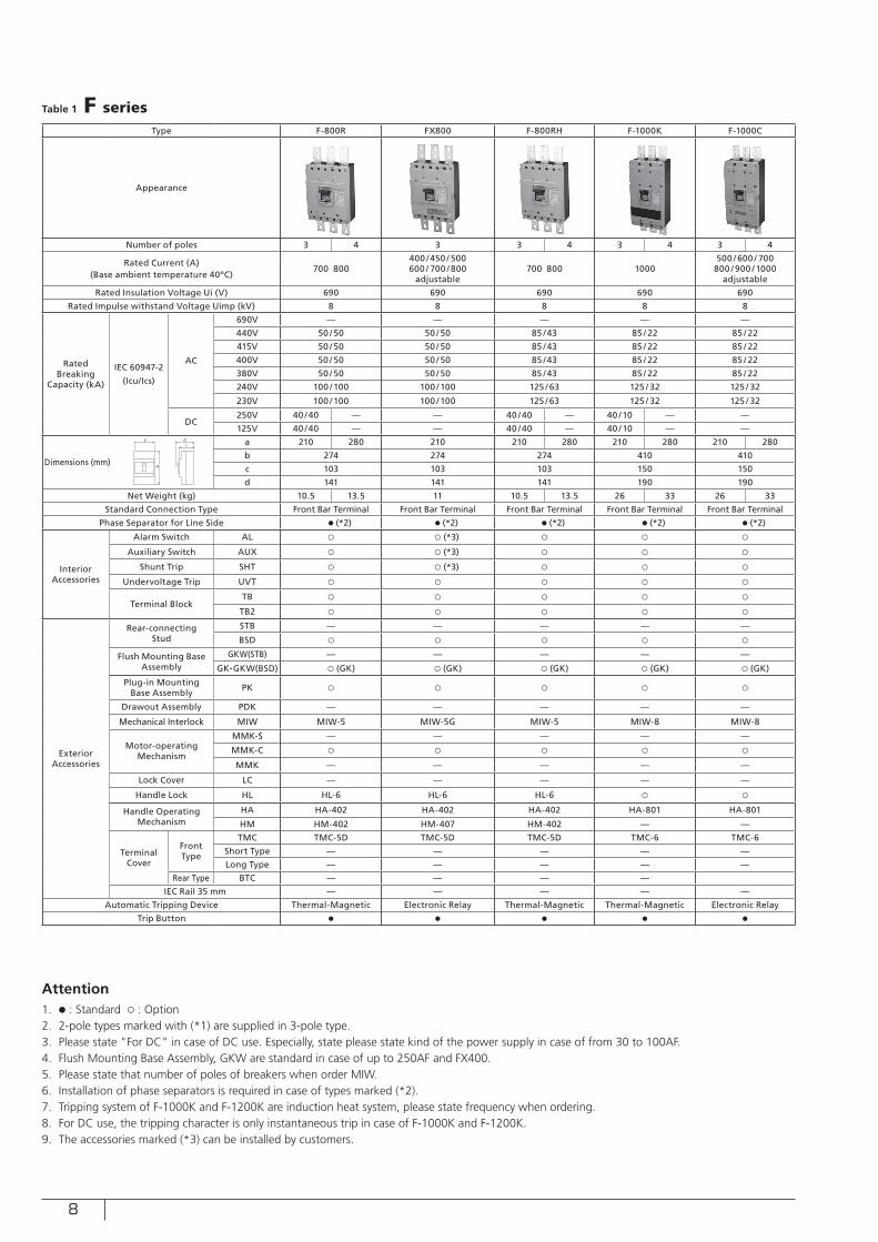
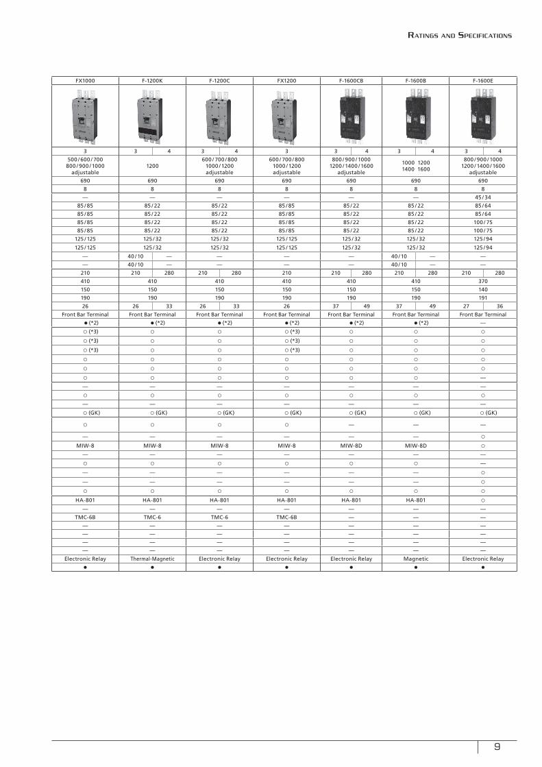
Type F-800R FX800 F-800RH F-1000K F-1000C FX1000 F-1200K F-1200C FX1200 F-1600CB F-1600B F-1600E
Appearance
Number of poles 3 4 3 3 4 3 4 3 4 3 3 4 3 4 3 3 4 3 4 3 4
Rated Current (A)(Base ambient temperature 40ºC)
700 800400 /450 / 500600 / 700 / 800
adjustable700 800 1000
500 / 600 / 700800 / 900 / 1000
adjustable
500 / 600 / 700800 / 900 / 1000
adjustable1200
600 / 700 / 8001000 / 1200adjustable
600 / 700 / 8001000 / 1200adjustable
800 / 900 / 10001200 / 1400 / 1600
adjustable
1000 12001400 1600
800 / 900 / 10001200 / 1400 / 1600
adjustable
Rated Insulation Voltage Ui (V) 690 690 690 690 690 690 690 690 690 690 690 690
Rated Impulse withstand Voltage Uimp (kV) 8 8 8 8 8 8 8 8 8 8 8 8
Rated Breaking
Capacity (kA)
IEC 60947-2
(Icu/Ics)
AC
690V — — — — — — — — — — — 45 / 34
440V 50 / 50 50 / 50 85 /43 85 / 22 85 / 22 85 / 85 85 / 22 85 / 22 85 / 85 85 / 22 85 / 22 85 / 64
415V 50 / 50 50 / 50 85 /43 85 / 22 85 / 22 85 / 85 85 / 22 85 / 22 85 / 85 85 / 22 85 / 22 85 / 64
400V 50 / 50 50 / 50 85 /43 85 / 22 85 / 22 85 / 85 85 / 22 85 / 22 85 / 85 85 / 22 85 / 22 100 / 75
380V 50 / 50 50 / 50 85 /43 85 / 22 85 / 22 85 / 85 85 / 22 85 / 22 85 / 85 85 / 22 85 / 22 100 / 75
240V 100 / 100 100 / 100 125 / 63 125 / 32 125 / 32 125 / 125 125 / 32 125 / 32 125 / 125 125 / 32 125 / 32 125 / 94
230V 100 / 100 100 / 100 125 / 63 125 / 32 125 / 32 125 / 125 125 / 32 125 / 32 125 / 125 125 / 32 125 / 32 125 / 94
DC250V 40 /40 — — 40 /40 — 40 / 10 — — — 40 / 10 — — — — 40 / 10 — —
125V 40 /40 — — 40 /40 — 40 / 10 — — — 40 / 10 — — — — 40 / 10 — —
Dimensions (mm)
a 210 280 210 210 280 210 280 210 280 210 210 280 210 280 210 210 280 210 280 210 280
b 274 274 274 410 410 410 410 410 410 410 410 370
c 103 103 103 150 150 150 150 150 150 150 150 140
d 141 141 141 190 190 190 190 190 190 190 190 191
Net Weight (kg) 10.5 13.5 11 10.5 13.5 26 33 26 33 26 26 33 26 33 26 37 49 37 49 27 36
Standard Connection Type Front Bar Terminal Front Bar Terminal Front Bar Terminal Front Bar Terminal Front Bar Terminal Front Bar Terminal Front Bar Terminal Front Bar Terminal Front Bar Terminal Front Bar Terminal Front Bar Terminal Front Bar Terminal
Phase Separator for Line Side ● (*2) ● (*2) ● (*2) ● (*2) ● (*2) ● (*2) ● (*2) ● (*2) ● (*2) ● (*2) ● (*2) —
Interior Accessories
Alarm Switch AL ○ ○ (*3) ○ ○ ○ ○ (*3) ○ ○ ○ (*3) ○ ○ ○
Auxiliary Switch AUX ○ ○ (*3) ○ ○ ○ ○ (*3) ○ ○ ○ (*3) ○ ○ ○
Shunt Trip SHT ○ ○ (*3) ○ ○ ○ ○ (*3) ○ ○ ○ (*3) ○ ○ ○
Undervoltage Trip UVT ○ ○ ○ ○ ○ ○ ○ ○ ○ ○ ○ ○
Terminal BlockTB ○ ○ ○ ○ ○ ○ ○ ○ ○ ○ ○ ○
TB2 ○ ○ ○ ○ ○ ○ ○ ○ ○ ○ ○ —
Exterior Accessories
Rear-connecting Stud
STB — — — — — — — — — — — —
BSD ○ ○ ○ ○ ○ ○ ○ ○ ○ ○ ○ ○
Flush Mounting Base Assembly
GKW(STB) — — — — — — — — — — — —
GK •GKW(BSD) ○ (GK) ○ (GK) ○ (GK) ○ (GK) ○ (GK) ○ (GK) ○ (GK) ○ (GK) ○ (GK) ○ (GK) ○ (GK) ○ (GK)
Plug-in Mounting Base Assembly PK ○ ○ ○ ○ ○ ○ ○ ○ ○ — — —
Drawout Assembly PDK — — — — — — — — — — — ○
Mechanical Interlock MIW MIW-5 MIW-5G MIW-5 MIW-8 MIW-8 MIW-8 MIW-8 MIW-8 MIW-8 MIW-8D MIW-8D ○
Motor-operating Mechanism
MMK-S — — — — — — — — — — — —
MMK-C ○ ○ ○ ○ ○ ○ ○ ○ ○ ○ ○ —
MMK — — — — — — — — — — — ○
Lock Cover LC — — — — — — — — — — — ○
Handle Lock HL HL-6 HL-6 HL-6 ○ ○ ○ ○ ○ ○ ○ ○ ○
Handle Operating Mechanism
HA HA-402 HA-402 HA-402 HA-801 HA-801 HA-801 HA-801 HA-801 HA-801 HA-801 HA-801 ○
HM HM-402 HM-407 HM-402 — — — — — — — — —
Terminal Cover
Front Type
TMC TMC-5D TMC-5D TMC-5D TMC-6 TMC-6 TMC-6B TMC-6 TMC-6 TMC-6B — — —
Short Type — — — — — — — — — — — —
Long Type — — — — — — — — — — — —
Rear Type BTC — — — — — — — — — — —
IEC Rail 35 mm — — — — — — — — — — — —
Automatic Tripping Device Thermal-Magnetic Electronic Relay Thermal-Magnetic Thermal-Magnetic Electronic Relay Electronic Relay Thermal-Magnetic Electronic Relay Electronic Relay Electronic Relay Magnetic Electronic Relay
Trip Button ● ● ● ● ● ● ● ● ● ● ● ●
a
b
dc
Table 1 F series
Attention1. ● : Standard ○ : Option2. 2-pole types marked with (*1) are supplied in 3-pole type. 3. Please state "For DC" in case of DC use. Especially, state please state kind of the power supply in case of from 30 to 100AF.4. Flush Mounting Base Assembly, GKW are standard in case of up to 250AF and FX400.5. Please state that number of poles of breakers when order MIW.6. Installation of phase separators is required in case of types marked (*2).7. Tripping system of F-1000K and F-1200K are induction heat system, please state frequency when ordering.8. For DC use, the tripping character is only instantaneous trip in case of F-1000K and F-1200K.9. The accessories marked (*3) can be installed by customers.
9
Type F-800R FX800 F-800RH F-1000K F-1000C FX1000 F-1200K F-1200C FX1200 F-1600CB F-1600B F-1600E
Appearance
Number of poles 3 4 3 3 4 3 4 3 4 3 3 4 3 4 3 3 4 3 4 3 4
Rated Current (A)(Base ambient temperature 40ºC)
700 800400 /450 / 500600 / 700 / 800
adjustable700 800 1000
500 / 600 / 700800 / 900 / 1000
adjustable
500 / 600 / 700800 / 900 / 1000
adjustable1200
600 / 700 / 8001000 / 1200adjustable
600 / 700 / 8001000 / 1200adjustable
800 / 900 / 10001200 / 1400 / 1600
adjustable
1000 12001400 1600
800 / 900 / 10001200 / 1400 / 1600
adjustable
Rated Insulation Voltage Ui (V) 690 690 690 690 690 690 690 690 690 690 690 690
Rated Impulse withstand Voltage Uimp (kV) 8 8 8 8 8 8 8 8 8 8 8 8
Rated Breaking
Capacity (kA)
IEC 60947-2
(Icu/Ics)
AC
690V — — — — — — — — — — — 45 / 34
440V 50 / 50 50 / 50 85 /43 85 / 22 85 / 22 85 / 85 85 / 22 85 / 22 85 / 85 85 / 22 85 / 22 85 / 64
415V 50 / 50 50 / 50 85 /43 85 / 22 85 / 22 85 / 85 85 / 22 85 / 22 85 / 85 85 / 22 85 / 22 85 / 64
400V 50 / 50 50 / 50 85 /43 85 / 22 85 / 22 85 / 85 85 / 22 85 / 22 85 / 85 85 / 22 85 / 22 100 / 75
380V 50 / 50 50 / 50 85 /43 85 / 22 85 / 22 85 / 85 85 / 22 85 / 22 85 / 85 85 / 22 85 / 22 100 / 75
240V 100 / 100 100 / 100 125 / 63 125 / 32 125 / 32 125 / 125 125 / 32 125 / 32 125 / 125 125 / 32 125 / 32 125 / 94
230V 100 / 100 100 / 100 125 / 63 125 / 32 125 / 32 125 / 125 125 / 32 125 / 32 125 / 125 125 / 32 125 / 32 125 / 94
DC250V 40 /40 — — 40 /40 — 40 / 10 — — — 40 / 10 — — — — 40 / 10 — —
125V 40 /40 — — 40 /40 — 40 / 10 — — — 40 / 10 — — — — 40 / 10 — —
Dimensions (mm)
a 210 280 210 210 280 210 280 210 280 210 210 280 210 280 210 210 280 210 280 210 280
b 274 274 274 410 410 410 410 410 410 410 410 370
c 103 103 103 150 150 150 150 150 150 150 150 140
d 141 141 141 190 190 190 190 190 190 190 190 191
Net Weight (kg) 10.5 13.5 11 10.5 13.5 26 33 26 33 26 26 33 26 33 26 37 49 37 49 27 36
Standard Connection Type Front Bar Terminal Front Bar Terminal Front Bar Terminal Front Bar Terminal Front Bar Terminal Front Bar Terminal Front Bar Terminal Front Bar Terminal Front Bar Terminal Front Bar Terminal Front Bar Terminal Front Bar Terminal
Phase Separator for Line Side ● (*2) ● (*2) ● (*2) ● (*2) ● (*2) ● (*2) ● (*2) ● (*2) ● (*2) ● (*2) ● (*2) —
Interior Accessories
Alarm Switch AL ○ ○ (*3) ○ ○ ○ ○ (*3) ○ ○ ○ (*3) ○ ○ ○
Auxiliary Switch AUX ○ ○ (*3) ○ ○ ○ ○ (*3) ○ ○ ○ (*3) ○ ○ ○
Shunt Trip SHT ○ ○ (*3) ○ ○ ○ ○ (*3) ○ ○ ○ (*3) ○ ○ ○
Undervoltage Trip UVT ○ ○ ○ ○ ○ ○ ○ ○ ○ ○ ○ ○
Terminal BlockTB ○ ○ ○ ○ ○ ○ ○ ○ ○ ○ ○ ○
TB2 ○ ○ ○ ○ ○ ○ ○ ○ ○ ○ ○ —
Exterior Accessories
Rear-connecting Stud
STB — — — — — — — — — — — —
BSD ○ ○ ○ ○ ○ ○ ○ ○ ○ ○ ○ ○
Flush Mounting Base Assembly
GKW(STB) — — — — — — — — — — — —
GK •GKW(BSD) ○ (GK) ○ (GK) ○ (GK) ○ (GK) ○ (GK) ○ (GK) ○ (GK) ○ (GK) ○ (GK) ○ (GK) ○ (GK) ○ (GK)
Plug-in Mounting Base Assembly PK ○ ○ ○ ○ ○ ○ ○ ○ ○ — — —
Drawout Assembly PDK — — — — — — — — — — — ○
Mechanical Interlock MIW MIW-5 MIW-5G MIW-5 MIW-8 MIW-8 MIW-8 MIW-8 MIW-8 MIW-8 MIW-8D MIW-8D ○
Motor-operating Mechanism
MMK-S — — — — — — — — — — — —
MMK-C ○ ○ ○ ○ ○ ○ ○ ○ ○ ○ ○ —
MMK — — — — — — — — — — — ○
Lock Cover LC — — — — — — — — — — — ○
Handle Lock HL HL-6 HL-6 HL-6 ○ ○ ○ ○ ○ ○ ○ ○ ○
Handle Operating Mechanism
HA HA-402 HA-402 HA-402 HA-801 HA-801 HA-801 HA-801 HA-801 HA-801 HA-801 HA-801 ○
HM HM-402 HM-407 HM-402 — — — — — — — — —
Terminal Cover
Front Type
TMC TMC-5D TMC-5D TMC-5D TMC-6 TMC-6 TMC-6B TMC-6 TMC-6 TMC-6B — — —
Short Type — — — — — — — — — — — —
Long Type — — — — — — — — — — — —
Rear Type BTC — — — — — — — — — — —
IEC Rail 35 mm — — — — — — — — — — — —
Automatic Tripping Device Thermal-Magnetic Electronic Relay Thermal-Magnetic Thermal-Magnetic Electronic Relay Electronic Relay Thermal-Magnetic Electronic Relay Electronic Relay Electronic Relay Magnetic Electronic Relay
Trip Button ● ● ● ● ● ● ● ● ● ● ● ●
Ratings and specifications
10
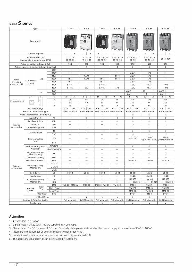
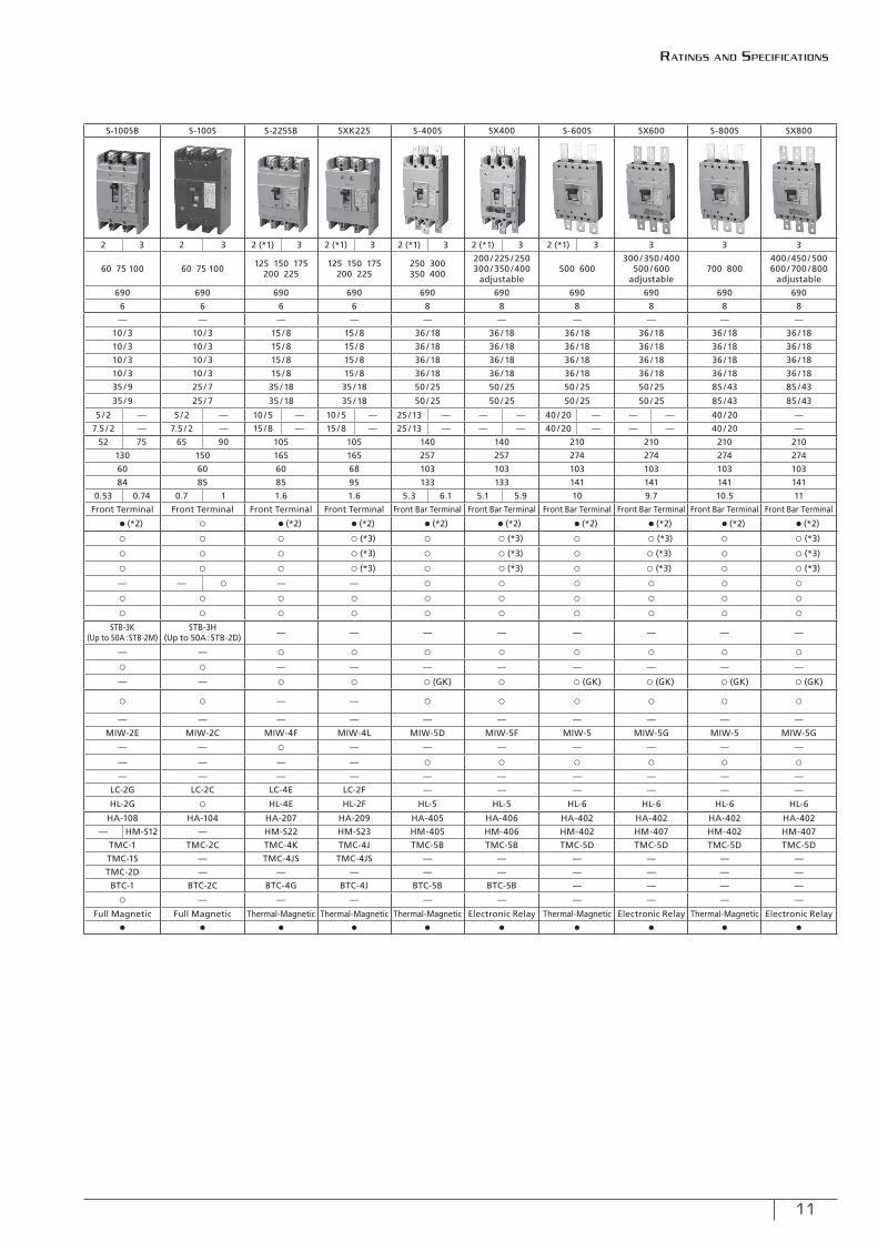
Type S-30S S-30E S-50E S-50EB S-50SB S-60RB S-100EB S-100SB S-100S S-225SB SXK225 S-400S SX400 S-600S SX600 S-800S SX800
Appearance
Number of poles 2 3 2 3 2 3 2 3 2 3 2 3 2 3 2 3 2 3 2 (*1) 3 2 (*1) 3 2 (*1) 3 2 (*1) 3 2 (*1) 3 3 3 3
Rated Current (A)(Base ambient temperature 40ºC)
3 5 1015 20 30
3 5 1015 20 30
5 10 15 2030 40 50
5 10 15 2030 40 50
5 10 15 2030 50
5 10 15 2030 50 60 60 75 100 60 75 100 60 75 100 125 150 175
200 225125 150 175
200 225250 300350 400
200 / 225 / 250300 / 350 /400
adjustable500 600
300 / 350 /400500 / 600
adjustable700 800
400 /450 / 500600 / 700 / 800
adjustable
Rated Insulation Voltage Ui (V) 500 500 500 500 690 690 250 690 690 690 690 690 690 690 690 690 690
Rated Impulse withstand Voltage Uimp (kV) — 4 — 4 6 6 6 6 6 6 6 8 8 8 8 8 8
Rated Breaking
Capacity (kA)
IEC 60947-2
(Icu/Ics)
AC
690V — — — — — — — — — — — — — — — — —
440V — — — — 2.5 / 1 5 / 2 — 10 / 3 10 / 3 15 / 8 15 / 8 36 / 18 36 / 18 36 / 18 36 / 18 36 / 18 36 / 18
415V — 1.5 / 1 — 1.5 / 1 2.5 / 1 5 / 2 — 10 / 3 10 / 3 15 / 8 15 / 8 36 / 18 36 / 18 36 / 18 36 / 18 36 / 18 36 / 18
400V 1.5 / 1 1.5 / 1 1.5 / 1 1.5 / 1 2.5 / 1 5 / 2 — 10 / 3 10 / 3 15 / 8 15 / 8 36 / 18 36 / 18 36 / 18 36 / 18 36 / 18 36 / 18
380V 1.5 / 1 — 1.5 / 1 — 2.5 / 1 5 / 2 — 10 / 3 10 / 3 15 / 8 15 / 8 36 / 18 36 / 18 36 / 18 36 / 18 36 / 18 36 / 18
240V 2.3 / 1.3 — 2.3 / 1.3 — 7.5 / 2 10 / 3 10 / 3 35 / 9 25 / 7 35 / 18 35 / 18 50 / 25 50 / 25 50 / 25 50 / 25 85 /43 85 /43
230V 2.5 / 1.3 5 / 2 2.3 / 1.3 5 / 2 7.5 / 2 10 / 3 10 / 3 35 / 9 25 / 7 35 / 18 35 / 18 50 / 25 50 / 25 50 / 25 50 / 25 85 /43 85 /43
DC250V — — — — 2.5 / 1 — 2.5 / 1 — 2.5 / 1 — 5 / 2 — 5 / 2 — 10 / 5 — 10 / 5 — 25 / 13 — — — 40 / 20 — — — 40 / 20 —
125V — — — — 5 / 2 — 5 / 2 — 5 / 2 — 7.5 / 2 — 7.5 / 2 — 15 / 8 — 15 / 8 — 25 / 13 — — — 40 / 20 — — — 40 / 20 —
Dimensions (mm)
a 50 75 50 75 50 75 50 75 52 75 52 75 52 75 52 75 65 90 105 105 140 140 210 210 210 210
b 95 96 96 96 130 130 130 130 150 165 165 257 257 274 274 274 274
c 60 60 60 60 60 60 60 60 60 60 68 103 103 103 103 103 103
d 79 76 79 76 84 84 84 84 85 85 95 133 133 141 141 141 141
Net Weight (kg) 0.32 0.47 0.25 0.37 0.32 0.47 0.25 0.37 0.48 0.6 0.5 0.7 0.5 0.7 0.53 0.74 0.7 1 1.6 1.6 5.3 6.1 5.1 5.9 10 9.7 10.5 11
Standard Connection Type Front Terminal Front Terminal Front Terminal Front Terminal Front Terminal Front Terminal Front Terminal Front Terminal Front Terminal Front Terminal Front Terminal Front Bar Terminal Front Bar Terminal Front Bar Terminal Front Bar Terminal Front Bar Terminal Front Bar Terminal
Phase Separator for Line Side (*2) — — — — ○ ○ ○ ● (*2) ○ ● (*2) ● (*2) ● (*2) ● (*2) ● (*2) ● (*2) ● (*2) ● (*2)
Interior Accessories
Alarm Switch AL — ○ — ○ ○ ○ ○ ○ ○ ○ ○ (*3) ○ ○ (*3) ○ ○ (*3) ○ ○ (*3)
Auxiliary Switch AUX — ○ — ○ ○ ○ ○ ○ ○ ○ ○ (*3) ○ ○ (*3) ○ ○ (*3) ○ ○ (*3)
Shunt Trip SHT — ○ — ○ ○ ○ ○ ○ ○ ○ ○ (*3) ○ ○ (*3) ○ ○ (*3) ○ ○ (*3)
Undervoltage Trip UVT — — — — — — — — — ○ — — ○ ○ ○ ○ ○ ○
Terminal BlockTB — — — — ○ ○ ○ ○ ○ ○ ○ ○ ○ ○ ○ ○ ○
TB2 — ○ — ○ ○ ○ ○ ○ ○ ○ ○ ○ ○ ○ ○ ○ ○
Exterior Accessories
Rear-connecting Stud
STB — — — — STB-2M STB-3K(Up to 50A :STB-2M)
STB-3K(Up to 50A :STB-2M)
STB-3K(Up to 50A :STB-2M)
STB-3H(Up to 50A :STB-2D) — — — — — — — —
BSD — — — — — — — — — ○ ○ ○ ○ ○ ○ ○ ○
Flush Mounting Base Assembly
GKW(STB) — — — — ○ ○ ○ ○ ○ — — — — — — — —
GK•GKW(BSD) — — — — — — — — — ○ ○ ○ (GK) ○ ○ (GK) ○ (GK) ○ (GK) ○ (GK)
Plug-in Mounting Base Assembly PK — — — — ○ ○ ○ ○ ○ — — ○ ○ ○ ○ ○ ○
Drawout Assembly PDK — — — — — — — — — — — — — — — — —
Mechanical Interlock MIW — — — — MIW-2E MIW-2E MIW-2E MIW-2E MIW-2C MIW-4F MIW-4L MIW-5D MIW-5F MIW-5 MIW-5G MIW-5 MIW-5G
Motor-operating Mechanism
MMK-S — — — — — — — — — ○ — — — — — — —
MMK-C — — — — — — — — — — — ○ ○ ○ ○ ○ ○
MMK — — — — — — — — — — — — — — — — —
Lock Cover LC LC-0B LC-03 LC-0B LC-03 LC-2G LC-2G LC-2G LC-2G LC-2C LC-4E LC-2F — — — — — —
Handle Lock HL — — — — HL-2G HL-2G HL-2G HL-2G ○ HL-4E HL-2F HL-5 HL-5 HL-6 HL-6 HL-6 HL-6
Handle Operating Mechanism
HA — — — — HA-108 HA-108 HA-108 HA-108 HA-104 HA-207 HA-209 HA-405 HA-406 HA-402 HA-402 HA-402 HA-402
HM — — — — HM-S12 — HM-S12 — HM-S12 — HM-S12 — HM-S22 HM-S23 HM-405 HM-406 HM-402 HM-407 HM-402 HM-407
Terminal Cover
Front Type
TMC TMC-0C TMC-0A TMC-0G TMC-0C TMC-0A TMC-0G TMC-1 TMC-1 TMC-1 TMC-1 TMC-2C TMC-4K TMC-4J TMC-5B TMC-5B TMC-5D TMC-5D TMC-5D TMC-5D
Short Type — — — — TMC-1S TMC-1S TMC-1S TMC-1S — TMC-4JS TMC-4JS — — — — — —
Long Type — — — — TMC-2D TMC-2D TMC-2D TMC-2D — — — — — — — — —
Rear Type BTC — — — — BTC-1 BTC-1 BTC-1 BTC-1 BTC-2C BTC-4G BTC-4J BTC-5B BTC-5B — — — —
IEC Rail 35 mm ● ● ● ● ○ ○ ○ ○ — — — — — — — — —
Automatic Tripping Device Full Magnetic Full Magnetic Full Magnetic Full Magnetic Full Magnetic Full Magnetic Full Magnetic Full Magnetic Full Magnetic Thermal-Magnetic Thermal-Magnetic Thermal-Magnetic Electronic Relay Thermal-Magnetic Electronic Relay Thermal-Magnetic Electronic Relay
Trip Button ● — ● — ● ● ● ● ● ● ● ● ● ● ● ● ●
a
b
dc
Table 2 S series
Attention1. ● : Standard ○ : Option2. 2-pole types marked with (*1) are supplied in 3-pole type. 3. Please state "For DC" in case of DC use . Especially, state please state kind of the power supply in case of from 30AF to 100AF.4. Please state that number of poles of breakers when order MIW.5. Installation of phase separators is required in case of types marked (*2).6. The accessories marked (*3) can be installed by customers.
11
Type S-30S S-30E S-50E S-50EB S-50SB S-60RB S-100EB S-100SB S-100S S-225SB SXK225 S-400S SX400 S-600S SX600 S-800S SX800
Appearance
Number of poles 2 3 2 3 2 3 2 3 2 3 2 3 2 3 2 3 2 3 2 (*1) 3 2 (*1) 3 2 (*1) 3 2 (*1) 3 2 (*1) 3 3 3 3
Rated Current (A)(Base ambient temperature 40ºC)
3 5 1015 20 30
3 5 1015 20 30
5 10 15 2030 40 50
5 10 15 2030 40 50
5 10 15 2030 50
5 10 15 2030 50 60 60 75 100 60 75 100 60 75 100 125 150 175
200 225125 150 175
200 225250 300350 400
200 / 225 / 250300 / 350 /400
adjustable500 600
300 / 350 /400500 / 600
adjustable700 800
400 /450 / 500600 / 700 / 800
adjustable
Rated Insulation Voltage Ui (V) 500 500 500 500 690 690 250 690 690 690 690 690 690 690 690 690 690
Rated Impulse withstand Voltage Uimp (kV) — 4 — 4 6 6 6 6 6 6 6 8 8 8 8 8 8
Rated Breaking
Capacity (kA)
IEC 60947-2
(Icu/Ics)
AC
690V — — — — — — — — — — — — — — — — —
440V — — — — 2.5 / 1 5 / 2 — 10 / 3 10 / 3 15 / 8 15 / 8 36 / 18 36 / 18 36 / 18 36 / 18 36 / 18 36 / 18
415V — 1.5 / 1 — 1.5 / 1 2.5 / 1 5 / 2 — 10 / 3 10 / 3 15 / 8 15 / 8 36 / 18 36 / 18 36 / 18 36 / 18 36 / 18 36 / 18
400V 1.5 / 1 1.5 / 1 1.5 / 1 1.5 / 1 2.5 / 1 5 / 2 — 10 / 3 10 / 3 15 / 8 15 / 8 36 / 18 36 / 18 36 / 18 36 / 18 36 / 18 36 / 18
380V 1.5 / 1 — 1.5 / 1 — 2.5 / 1 5 / 2 — 10 / 3 10 / 3 15 / 8 15 / 8 36 / 18 36 / 18 36 / 18 36 / 18 36 / 18 36 / 18
240V 2.3 / 1.3 — 2.3 / 1.3 — 7.5 / 2 10 / 3 10 / 3 35 / 9 25 / 7 35 / 18 35 / 18 50 / 25 50 / 25 50 / 25 50 / 25 85 /43 85 /43
230V 2.5 / 1.3 5 / 2 2.3 / 1.3 5 / 2 7.5 / 2 10 / 3 10 / 3 35 / 9 25 / 7 35 / 18 35 / 18 50 / 25 50 / 25 50 / 25 50 / 25 85 /43 85 /43
DC250V — — — — 2.5 / 1 — 2.5 / 1 — 2.5 / 1 — 5 / 2 — 5 / 2 — 10 / 5 — 10 / 5 — 25 / 13 — — — 40 / 20 — — — 40 / 20 —
125V — — — — 5 / 2 — 5 / 2 — 5 / 2 — 7.5 / 2 — 7.5 / 2 — 15 / 8 — 15 / 8 — 25 / 13 — — — 40 / 20 — — — 40 / 20 —
Dimensions (mm)
a 50 75 50 75 50 75 50 75 52 75 52 75 52 75 52 75 65 90 105 105 140 140 210 210 210 210
b 95 96 96 96 130 130 130 130 150 165 165 257 257 274 274 274 274
c 60 60 60 60 60 60 60 60 60 60 68 103 103 103 103 103 103
d 79 76 79 76 84 84 84 84 85 85 95 133 133 141 141 141 141
Net Weight (kg) 0.32 0.47 0.25 0.37 0.32 0.47 0.25 0.37 0.48 0.6 0.5 0.7 0.5 0.7 0.53 0.74 0.7 1 1.6 1.6 5.3 6.1 5.1 5.9 10 9.7 10.5 11
Standard Connection Type Front Terminal Front Terminal Front Terminal Front Terminal Front Terminal Front Terminal Front Terminal Front Terminal Front Terminal Front Terminal Front Terminal Front Bar Terminal Front Bar Terminal Front Bar Terminal Front Bar Terminal Front Bar Terminal Front Bar Terminal
Phase Separator for Line Side (*2) — — — — ○ ○ ○ ● (*2) ○ ● (*2) ● (*2) ● (*2) ● (*2) ● (*2) ● (*2) ● (*2) ● (*2)
Interior Accessories
Alarm Switch AL — ○ — ○ ○ ○ ○ ○ ○ ○ ○ (*3) ○ ○ (*3) ○ ○ (*3) ○ ○ (*3)
Auxiliary Switch AUX — ○ — ○ ○ ○ ○ ○ ○ ○ ○ (*3) ○ ○ (*3) ○ ○ (*3) ○ ○ (*3)
Shunt Trip SHT — ○ — ○ ○ ○ ○ ○ ○ ○ ○ (*3) ○ ○ (*3) ○ ○ (*3) ○ ○ (*3)
Undervoltage Trip UVT — — — — — — — — — ○ — — ○ ○ ○ ○ ○ ○
Terminal BlockTB — — — — ○ ○ ○ ○ ○ ○ ○ ○ ○ ○ ○ ○ ○
TB2 — ○ — ○ ○ ○ ○ ○ ○ ○ ○ ○ ○ ○ ○ ○ ○
Exterior Accessories
Rear-connecting Stud
STB — — — — STB-2M STB-3K(Up to 50A :STB-2M)
STB-3K(Up to 50A :STB-2M)
STB-3K(Up to 50A :STB-2M)
STB-3H(Up to 50A :STB-2D) — — — — — — — —
BSD — — — — — — — — — ○ ○ ○ ○ ○ ○ ○ ○
Flush Mounting Base Assembly
GKW(STB) — — — — ○ ○ ○ ○ ○ — — — — — — — —
GK•GKW(BSD) — — — — — — — — — ○ ○ ○ (GK) ○ ○ (GK) ○ (GK) ○ (GK) ○ (GK)
Plug-in Mounting Base Assembly PK — — — — ○ ○ ○ ○ ○ — — ○ ○ ○ ○ ○ ○
Drawout Assembly PDK — — — — — — — — — — — — — — — — —
Mechanical Interlock MIW — — — — MIW-2E MIW-2E MIW-2E MIW-2E MIW-2C MIW-4F MIW-4L MIW-5D MIW-5F MIW-5 MIW-5G MIW-5 MIW-5G
Motor-operating Mechanism
MMK-S — — — — — — — — — ○ — — — — — — —
MMK-C — — — — — — — — — — — ○ ○ ○ ○ ○ ○
MMK — — — — — — — — — — — — — — — — —
Lock Cover LC LC-0B LC-03 LC-0B LC-03 LC-2G LC-2G LC-2G LC-2G LC-2C LC-4E LC-2F — — — — — —
Handle Lock HL — — — — HL-2G HL-2G HL-2G HL-2G ○ HL-4E HL-2F HL-5 HL-5 HL-6 HL-6 HL-6 HL-6
Handle Operating Mechanism
HA — — — — HA-108 HA-108 HA-108 HA-108 HA-104 HA-207 HA-209 HA-405 HA-406 HA-402 HA-402 HA-402 HA-402
HM — — — — HM-S12 — HM-S12 — HM-S12 — HM-S12 — HM-S22 HM-S23 HM-405 HM-406 HM-402 HM-407 HM-402 HM-407
Terminal Cover
Front Type
TMC TMC-0C TMC-0A TMC-0G TMC-0C TMC-0A TMC-0G TMC-1 TMC-1 TMC-1 TMC-1 TMC-2C TMC-4K TMC-4J TMC-5B TMC-5B TMC-5D TMC-5D TMC-5D TMC-5D
Short Type — — — — TMC-1S TMC-1S TMC-1S TMC-1S — TMC-4JS TMC-4JS — — — — — —
Long Type — — — — TMC-2D TMC-2D TMC-2D TMC-2D — — — — — — — — —
Rear Type BTC — — — — BTC-1 BTC-1 BTC-1 BTC-1 BTC-2C BTC-4G BTC-4J BTC-5B BTC-5B — — — —
IEC Rail 35 mm ● ● ● ● ○ ○ ○ ○ — — — — — — — — —
Automatic Tripping Device Full Magnetic Full Magnetic Full Magnetic Full Magnetic Full Magnetic Full Magnetic Full Magnetic Full Magnetic Full Magnetic Thermal-Magnetic Thermal-Magnetic Thermal-Magnetic Electronic Relay Thermal-Magnetic Electronic Relay Thermal-Magnetic Electronic Relay
Trip Button ● — ● — ● ● ● ● ● ● ● ● ● ● ● ● ●
Ratings and specifications
12
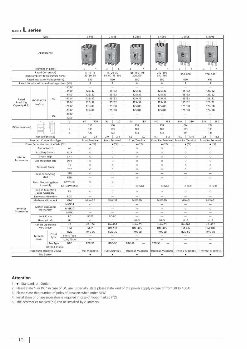
Type L-50E L-100E L-225E L-400E L-600E L-800E
Appearance
Number of poles 3 4 3 4 3 4 3 4 3 4 3 4
Rated Current (A)(Base ambient temperature 40ºC)
5 10 1520 30 50
15 20 3050 60 75 100
125 150 175200 225
250 300350 400 500 600 700 800
Rated Insulation Voltage Ui (V) 690 690 690 690 690 690
Rated Impulse withstand Voltage Uimp (kV) 8 8 8 8 8 8
Rated Breaking
Capacity (kA)
IEC 60947-2
(Icu/Ics)
AC
690V — — — — — —
440V 125 / 32 125 / 32 125 / 32 125 / 32 125 / 32 125 / 32
415V 125 / 32 125 / 32 125 / 32 125 / 32 125 / 32 125 / 32
400V 125 / 32 125 / 32 125 / 32 125 / 32 125 / 32 125 / 32
380V 125 / 32 125 / 32 125 / 32 125 / 32 125 / 32 125 / 32
240V 175 / 88 175 / 88 175 / 88 175 / 88 175 / 88 175 / 88
230V 175 / 88 175 / 88 175 / 88 175 / 88 175 / 88 175 / 88
DC250V — — — — — —
125V — — — — — —
Dimensions (mm)
a 90 120 90 120 140 185 140 185 210 280 210 280
b 150 150 257 257 274 274
c 103 103 103 103 103 103
d 123 123 133 133 141 141
Net Weight (kg) 2.0 2.5 2.0 2.5 5.2 7.0 6.1 8.2 10.0 13.0 10.5 13.5
Standard Connection Type Front Terminal Front Terminal Front Terminal Front Bar Terminal Front Bar Terminal Front Bar Terminal
Phase Separator for Line Side (*2) ● (*2) ● (*2) ● (*2) ● (*2) ● (*2) ● (*2)
Interior Accessories
Alarm Switch AL ○ ○ ○ ○ ○ ○
Auxiliary Switch AUX ○ ○ ○ ○ ○ ○
Shunt Trip SHT ○ ○ ○ ○ ○ ○
Undervoltage Trip UVT ○ ○ ○ ○ ○ ○
Terminal BlockTB ○ ○ ○ ○ ○ ○
TB2 ○ ○ ○ ○ ○ ○
Exterior Accessories
Rear-connecting Stud
STB ○ ○ — — — —
BSD — — ○ ○ ○ ○
Flush Mounting Base Assembly
GKW(STB) ○ ○ — — — —
GK•GKW(BSD) — — ○ (GK) ○ (GK) ○ (GK) ○ (GK)
Plug-in Mounting Base Assembly PK ○ ○ ○ ○ ○ ○
Drawout Assembly PDK — — — — — —
Mechanical Interlock MIW MIW-3E MIW-3E MIW-5D MIW-5D MIW-5 MIW-5
Motor-operating Mechanism
MMK-S ○ ○ — — — —
MMK-C — — ○ ○ ○ ○
MMK — — — — — —
Lock Cover LC LC-2C LC-2C — — — —
Handle Lock HL ○ ○ HL-5 HL-5 HL-6 HL-6
Handle Operating Mechanism
HA HA-106 HA-106 HA-405 HA-405 HA-402 HA-402
HM HM-S11 HM-S11 HM-405 HM-405 HM-402 HM-402
Terminal Cover
Front Type
TMC TMC-3C TMC-3C TMC-5B TMC-5B TMC-5D TMC-5D
Short Type — — — — — —
Long Type — — — — — —
Rear Type BTC BTC-3C BTC-3C BTC-5B — BTC-5B — — —
IEC Rail 35 mm — — — — — —
Automatic Tripping Device Full Magnetic Full Magnetic Thermal-Magnetic Thermal-Magnetic Thermal-Magnetic Thermal-Magnetic
Trip Button ● ● ● ● ● ●
a
b
dc
Table 3 L series
Attention1. ● : Standard ○ : Option2. Please state "For DC" in case of DC use. Especially, state please state kind of the power supply in case of from 30 to 100AF.3. Please state that number of poles of breakers when order MIW.4. Installation of phase separators is required in case of types marked (*2).5. The accessories marked (*3) can be installed by customers.
13
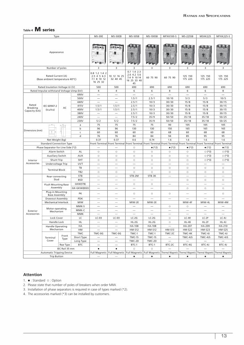
Type MS-30E MS-50EB MS-50SB MS-100SB MFXK100-S MS-225SB MSXK225 MFXK225-S
Appearance
Number of poles 3 3 3 3 3 3 3 3
Rated Current (A)(Base ambient temperature 40ºC)
0.8 1.2 1.4 2 2.5 4 5 6.3 7.1 8 10 12
16 25 32
10 12 16 25 32 40 45
0.7 1.4 2.3 2.6 4.2 5.6 7.4 9 10 14
16 25 33 40 45
60 75 90 60 75 90 125 150175 225
125 150175 225
125 150175 225
Rated Insulation Voltage Ui (V) 500 500 690 690 690 690 690 690
Rated Impulse withstand Voltage Uimp (kV) 4 4 6 6 8 6 6 8
Rated Breaking
Capacity (kA)
IEC 60947-2
(Icu/Ics)AC
690V — — — — — — — —
500V — — 1.5 / 1 2.5 / 1 10 / 10 5 / 3 5 / 3 10 / 5
440V — — 2.5 / 1 10 / 3 30 / 30 15 / 8 15 / 8 30 / 15
415V 1.5 / 1 1.5 / 1 2.5 / 1 10 / 3 30 / 30 15 / 8 15 / 8 30 / 15
400V 1.5 / 1 1.5 / 1 2.5 / 1 10 / 3 30 / 30 15 / 8 15 / 8 30 / 15
380V — — 2.5 / 1 10 / 3 30 / 30 15 / 8 15 / 8 30 / 15
240V — — 7.5 / 2 35 / 9 50 / 50 35 / 18 35 / 18 50 / 25
230V 5 / 2 5 / 2 7.5 / 2 35 / 9 50 / 50 35 / 18 35 / 18 50 / 25
Dimensions (mm)
a 75 75 75 75 90 105 105 105
b 96 96 130 130 150 165 165 165
c 60 60 60 60 68 60 68 68
d 76 76 84 84 94 85 95 95
Net Weight (kg) 0.37 0.37 0.6 0.74 1.6 1.6 1.6 1.6
Standard Connection Type Front Terminal Front Terminal Front Terminal Front Terminal Front Terminal Front Terminal Front Terminal Front Terminal
Phase Separator for Line Side (*2) — — ○ ● (*2) ● (*2) ● (*2) ● (*2) ● (*2)
Interior Accessories
Alarm Switch AL ○ ○ ○ ○ ○ ○ ○ (*3) ○ (*3)
Auxiliary Switch AUX ○ ○ ○ ○ ○ ○ ○ (*3) ○ (*3)
Shunt Trip SHT ○ ○ ○ ○ ○ ○ ○ (*3) ○ (*3)
Undervoltage Trip UVT — — — — — — — —
Terminal BlockTB — — ○ ○ ○ ○ ○ ○
TB2 ○ ○ ○ ○ ○ ○ ○ ○
Exterior Accessories
Rear-connecting Stud
STB — — STB-2M STB-3K — — — —
BSD — — — — ○ ○ ○
Flush Mounting Base Assembly
GKW(STB) — — ○ ○ — — — —
GK•GKW(BSD) — — — — ○ ○ ○
Plug-in Mounting Base Assembly PK — — ○ ○ ○ — — ○
Drawout Assembly PDK — — — — — — — —
Mechanical Interlock MIW — — MIW-2E MIW-2E MIW-4F MIW-4L MIW-4M
Motor-operating Mechanism
MMK-S — — — — ○ ○ — —
MMK-C — — — — — — — —
MMK — — — — — — — —
Lock Cover LC LC-03 LC-03 LC-2G LC-2G ○ LC-4E LC-2F LC-4J
Handle Lock HL — — HL-2G HL-2G ○ HL-4E HL-2F HL-4J
Handle Operating Mechanism
HA — — HA-108 HA-108 — HA-207 HA-209 HA-210
HM — — HM-S12 HM-S12 HM-S13 HM-S22 HM-S23 HM-S25
Terminal Cover
Front Type
TMC TMC-0G TMC-0G TMC-1 TMC-1 TMC-2C TMC-4K TMC-4J TMC-4J
Short Type — — TMC-1S TMC-1S — TMC-4JS TMC-4JS TMC-4JS
Long Type — — TMC-2D TMC-2D — — — —
Rear Type BTC — — BTC-1 BTC-1 BTC-2C BTC-4G BTC-4J BTC-4J
IEC Rail 35 mm ● ● ○ ○ — — — —
Automatic Tripping Device Full Magnetic Full Magnetic Full Magnetic Full Magnetic Thermal-Magnetic Thermal-Magnetic Thermal-Magnetic Thermal-Magnetic
Trip Button — — ● ● ● ● ● ●
a
b
dc
Table 4 M series
Attention1. ● : Standard ○ : Option2. Please state that number of poles of breakers when order MIW.3. Installation of phase separators is required in case of types marked (*2).4. The accessories marked (*3) can be installed by customers.
Ratings and specifications
14
Min. value
Max. value of less than 30A
Sec.
Min
.H
r.
Trip
pin
g T
ime
Max. value of 31 to 50A
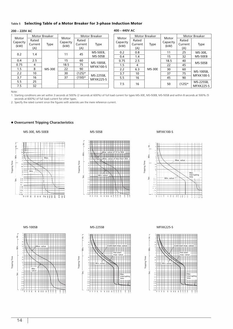
Table 5 Selecting Table of a Motor Breaker for 3-phase Induction Motor
Motor Capacity
(kW)
Motor BreakerMotor
Capacity (kW)
Motor BreakerRated
Current (A)
TypeRated
Current (A)
Type
0.2 1.4
MS-30E
11 45MS-50EB, MS-50SB
0.4 2.5 15 60MS-100SB,MFXK100-S
0.75 4 18.5 751.5 8 22 902.2 10 30 (125)*
MS-225SB,MFXK225-S
3.7 16 37 (150)*5.5 257.5 32
Motor Capacity
(kW)
Motor BreakerMotor
Capacity (kW)
Motor BreakerRated
Current (A)
TypeRated
Current (A)
Type
0.2 0.8
MS-30E
11 25 MS-30E, MS-50EB0.4 1.4 15 32
0.75 2.5 18.5 40MS-50SB
1.5 4 22 452.2 6.3 30 60
MS-100SB,MFXK100-S
3.7 10 37 755.5 16 45 90
7.5 16 50 (125)*MS-225SB,MFXK225-S
Note:1. Starting conditions are set within 3 seconds at 500% (2 seconds at 600%) of full load current for types MS-30E, MS-50EB, MS-50SB and within 8 seconds at 500% (5
seconds at 600%) of full load current for other types.2. Specify the rated current since the figures with asterisks are the mere reference current.
● Overcurrent Tripping Characteristics
MS-30E, MS-50EB
MS-100SB
MS-50SB
MS-225SB
MFXK100-S
MFXK225-S
200 – 220V AC 400 – 440V AC
Min.
Max.
Sec.
Min
.H
r.
Trip
pin
g T
ime
Trip
pin
g T
ime
Trip
pin
g T
ime
Trip
pin
g T
ime
Sec.
Sec.
Min
.
Min
.
Hr.
Hr.
Min. value Min. value
Max. interrupting time
Max. interrupting time
Min. value
Max. value
Sec.
Min
.H
r.
Cold start max. value Cold start max. value
Hot startmax. value
Hot startmax. value
Max. value
Sec.
Min
.H
r.
Trip
pin
g T
ime
Min. value
Max. interrupting time
15
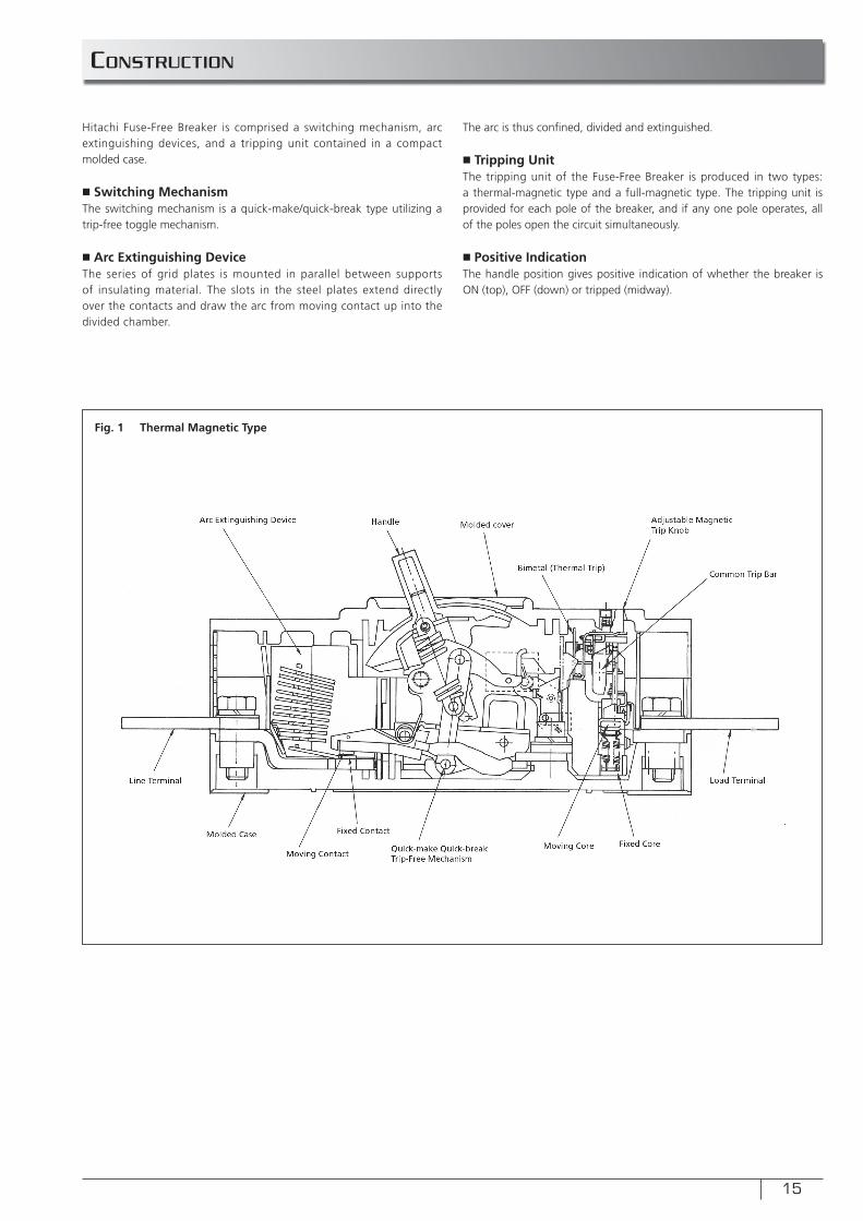
constRUction
Hitachi Fuse-Free Breaker is comprised a switching mechanism, arc extinguishing devices, and a tripping unit contained in a compact molded case.
■ Switching MechanismThe switching mechanism is a quick-make/quick-break type utilizing a trip-free toggle mechanism.
■ Arc Extinguishing DeviceThe series of grid plates is mounted in parallel between supports of insulating material. The slots in the steel plates extend directly over the contacts and draw the arc from moving contact up into the divided chamber.
The arc is thus confi ned, divided and extinguished.
■ Tripping UnitThe tripping unit of the Fuse-Free Breaker is produced in two types: a thermal-magnetic type and a full-magnetic type. The tripping unit is provided for each pole of the breaker, and if any one pole operates, all of the poles open the circuit simultaneously.
■ Positive IndicationThe handle position gives positive indication of whether the breaker is ON (top), OFF (down) or tripped (midway).
Fig. 1 Thermal Magnetic Type
16
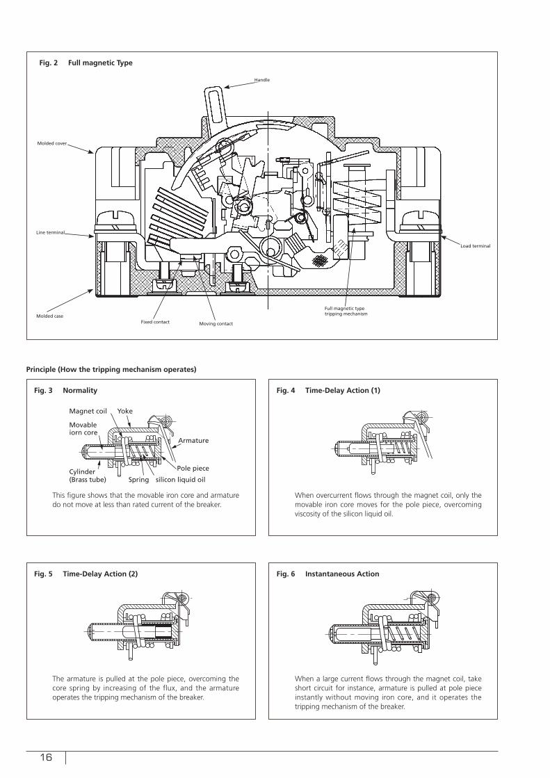
Fig. 2 Full magnetic Type
Fig. 3 Normality
Fig. 5 Time-Delay Action (2)
Fig. 4 Time-Delay Action (1)
Fig. 6 Instantaneous Action
Principle (How the tripping mechanism operates)
Movable iorn core
Yoke
Armature
Pole piece
silicon liquid oilSpringCylinder(Brass tube)
Magnet coil
This figure shows that the movable iron core and armature do not move at less than rated current of the breaker.
The armature is pulled at the pole piece, overcoming the core spring by increasing of the flux, and the armature operates the tripping mechanism of the breaker.
When overcurrent flows through the magnet coil, only the movable iron core moves for the pole piece, overcoming viscosity of the silicon liquid oil.
When a large current flows through the magnet coil, take short circuit for instance, armature is pulled at pole piece instantly without moving iron core, and it operates the tripping mechanism of the breaker.
Full magnetic type tripping mechanism
Load terminal
Moving contactFixed contactMolded case
Molded cover
Line terminal
Handle
17
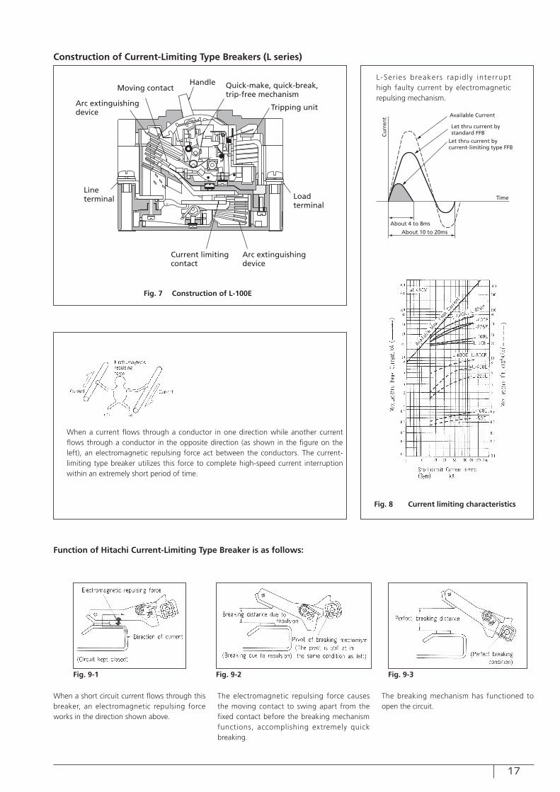
Fig. 7 Construction of L-100E
Construction of Current-Limiting Type Breakers (L series)
Arc extinguishingdevice
Lineterminal
Current limitingcontact
Arc extinguishingdevice
Loadterminal
Tripping unit
Quick-make, quick-break, trip-free mechanism
HandleMoving contact
About 4 to 8ms
About 10 to 20ms
Time
Available Current
Let thru current by standard FFB
Let thru current by current-limiting type FFB
Cu
rren
t
L-Ser ies breakers rapidly interrupt high faulty current by electromagnetic repulsing mechanism.
When a current flows through a conductor in one direction while another current flows through a conductor in the opposite direction (as shown in the figure on the left), an electromagnetic repulsing force act between the conductors. The current-limiting type breaker utilizes this force to complete high-speed current interruption within an extremely short period of time.
Function of Hitachi Current-Limiting Type Breaker is as follows:
When a short circuit current flows through this breaker, an electromagnetic repulsing force works in the direction shown above.
The electromagnetic repulsing force causes the moving contact to swing apart from the fixed contact before the breaking mechanism functions, accomplishing extremely quick breaking.
The breaking mechanism has functioned to open the circuit.
Fig. 8 Current limiting characteristics
Fig. 9-1 Fig. 9-2 Fig. 9-3
18
Excellent Current Limiting Function Double Instantaneous Trip*
Higher MT current Reduces Miss trip by motors rush Current Easy Coordination*
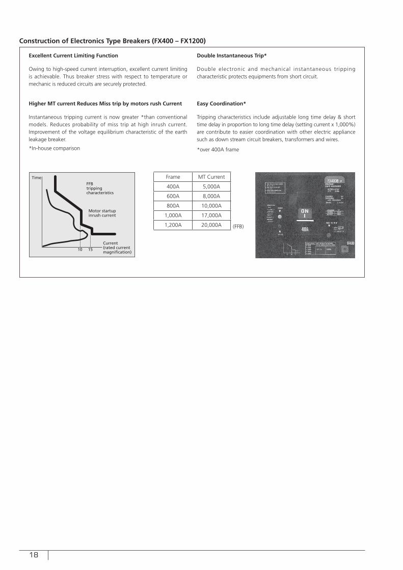
Construction of Electronics Type Breakers (FX400 – FX1200)
Owing to high-speed current interruption, excellent current limiting is achievable. Thus breaker stress with respect to temperature or mechanic is reduced circuits are securely protected.
Double electronic and mechanical instantaneous tripping characteristic protects equipments from short circuit.
Instantaneous tripping current is now greater *than conventional models. Reduces probability of miss trip at high inrush current. Improvement of the voltage equilibrium characteristic of the earth leakage breaker.
*In-house comparison
Tripping characteristics include adjustable long time delay & short time delay in proportion to long time delay (setting current x 1,000%) are contribute to easier coordination with other electric appliance such as down stream circuit breakers, transformers and wires.
*over 400A frame
Frame MT Current
400A 5,000A
600A 8,000A
800A 10,000A
1,000A 17,000A
1,200A 20,000A (FFB)
TimeFFBtrippingcharacteristics
Motor startupinrush current
Current(rated current magni�cation)
10 15
19
CHARACTERISTICS
1. Overcurrent Tripping
Because of its tripping device with proper time-delay characteristics, Hitachi Fuse-Free Breaker automatically opens circuits for overcurrents up to about 800% of its ampere rating. For heavy short-circuit currents, its instantaneous magnetic tripping device functions to break the circuit.These characteristics are specified in Circuit Breakers IEC60947-2, as shown in Table 6, according to which Hitachi Fuse-Free Breaker is designed.
<Base ambient temperature>Tripping device of Hitachi Fuse-Free Breaker is factory-adjusted for application at an ambient temperature of 40ºC, the base ambient temperature specifi ed by IEC standard.
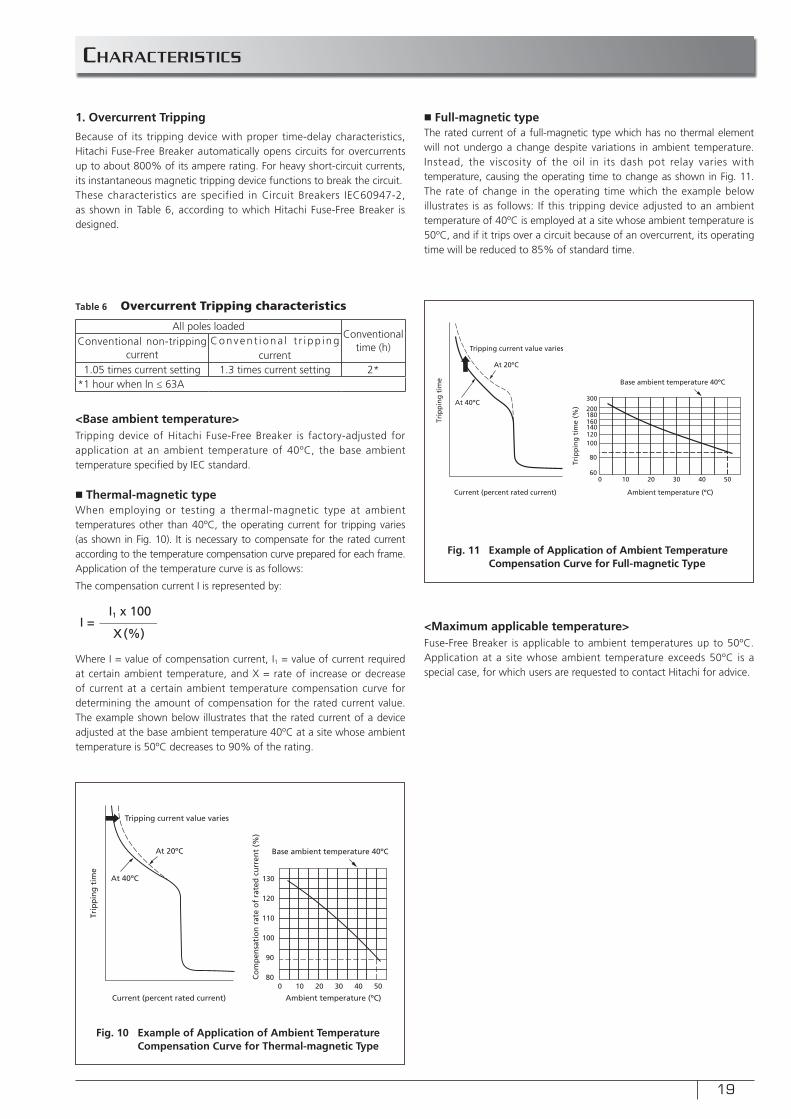
■ Thermal-magnetic typeWhen employing or testing a thermal-magnetic type at ambient temperatures other than 40ºC, the operating current for tripping varies (as shown in Fig. 10). It is necessary to compensate for the rated current according to the temperature compensation curve prepared for each frame.Application of the temperature curve is as follows:
The compensation current I is represented by:
Where I = value of compensation current, I1 = value of current required at certain ambient temperature, and X = rate of increase or decrease of current at a certain ambient temperature compensation curve for determining the amount of compensation for the rated current value. The example shown below illustrates that the rated current of a device adjusted at the base ambient temperature 40ºC at a site whose ambient temperature is 50ºC decreases to 90% of the rating.
<Maximum applicable temperature>Fuse-Free Breaker is applicable to ambient temperatures up to 50ºC. Application at a site whose ambient temperature exceeds 50ºC is a special case, for which users are requested to contact Hitachi for advice.
■ Full-magnetic typeThe rated current of a full-magnetic type which has no thermal element will not undergo a change despite variations in ambient temperature. Instead, the viscosity of the oil in its dash pot relay varies with temperature, causing the operating time to change as shown in Fig. 11. The rate of change in the operating time which the example below illustrates is as follows: If this tripping device adjusted to an ambient temperature of 40ºC is employed at a site whose ambient temperature is 50ºC, and if it trips over a circuit because of an overcurrent, its operating time will be reduced to 85% of standard time.
Table 6 Overcurrent Tripping characteristics
All poles loadedConventional
time (h)Conventional non-tripping current
Conven t i ona l t r i pp i ng current
1.05 times current setting 1.3 times current setting 2**1 hour when ln ≤ 63A
I =I1 x 100
X(%)
Current (percent rated current)
At 40ºC
At 20ºC
Tripping current value varies
0 10 20 30 40 5080
90
100
110
120
130
Base ambient temperature 40ºC
Ambient temperature (ºC)
Trip
pin
g t
ime
Co
mp
ensa
tio
n r
ate
of
rate
d c
urr
ent
(%)
Trip
pin
g t
ime
Trip
pin
g t
ime
(%)At 40ºC
At 20ºC
Tripping current value varies
Current (percent rated current) Ambient temperature (ºC)
0 10 20 30 40 5060
80
100120140160180200
300
Base ambient temperature 40ºC
Fig. 10 Example of Application of Ambient Temperature Compensation Curve for Thermal-magnetic Type
Fig. 11 Example of Application of Ambient Temperature Compensation Curve for Full-magnetic Type
20
CAUTION
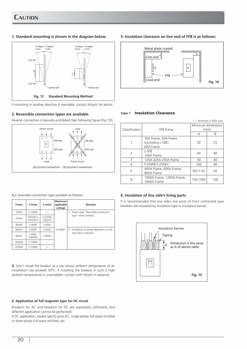
1. Standard mounting is shown in the diagram below.
2. Reversible connection types are available.
Reverse connection is basically prohibited (See following fi gure (Fig.13))
5. Insulation clearance on line end of FFB is as follows:
4. Application of full magnetic type for DC circuit
Breakers for AC and breakers for DC are separately calibrated, and different application cannot be performed.If DC application, please specify pure DC, single-phase full-wave rectifi ed or three-phase full-wave rectifi ed, etc.
3. Don’t install the breaker at a site whose ambient temperature of an installation site exceeds 50ºC. If installing the breaker in such a high ambient temperature is unavoidable, contact with Hitachi in advance.
If mounting in another direction is inevitable, contact Hitachi for advice.
But reversible connection type available as follows: 6. Insulation of line side’s living parts
It is recommended that line side’s live parts of front connected type breakers are insulated by insulation tape or insulation barrier.
15 degree or less
15 degree or less
15 degree or less
15 degree or less
Line end
Load end
Vertical wall Vertical wall
A B
Metal plate coated
FFB
Line end
Load end
ON side
OFF side
Power source
Load
(a) Correct connection (b) Incorrect connection
Power source
Load
OFF side
ON side
Frame F series S seriesMaximum applicable
voltageRemarks
100AF F-100KB —
AC460V
1. Please state "Reversible connection type" when ordered.
225AFFXK250-S,FXK250-H
S-225SB,SXK225
400AF F-400R S-400S
600AF F-600F S-600S 2. Installation of phase separators on the load side is required.
800AFF-800F,
F-800RHS-800S
1000AF F-1000K —
1200AF F-1200K —
Table 7 Insulation Clearance
Classifi cation FFB frameMinimum dimensions
(mm)A B
130A Frame, 50A Frame (Excluding L-50E) 60A Frame
30 25
2L-50E100A Frame
40 40
3 125A 225A 250A Frame 50 404 F-250FB F-250KC 100 40
5400A Frame, 600A Frame, 800A Frame
80 (110) 50
61000A Frame, 1200A Frame, 1600A Frame
150 (190) 100
Taping
Insulation barrier
Dimension is the same as A of above tableA
( ) dimension is 400V class
Fig. 12 Standard Mounting Method
Fig. 15
Fig. 14
21
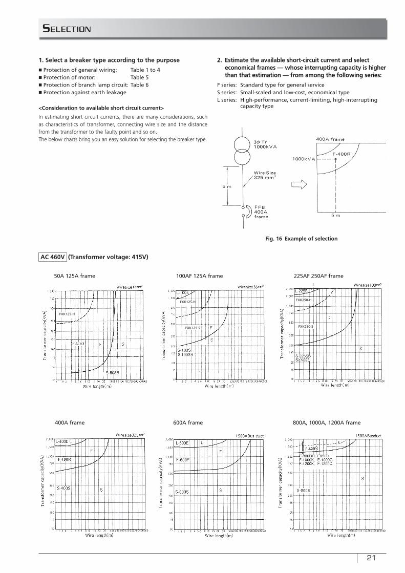
SELECTION
1. Select a breaker type according to the purpose
■ Protection of general wiring: Table 1 to 4■ Protection of motor: Table 5■ Protection of branch lamp circuit: Table 6■ Protection against earth leakage
2. Estimate the available short-circuit current and select economical frames — whose interrupting capacity is higher than that estimation — from among the following series:
F series: Standard type for general serviceS series: Small-scaled and low-cost, economical typeL series: High-performance, current-limiting, high-interrupting capacity type<Consideration to available short circuit current>
In estimating short circuit currents, there are many considerations, such as characteristics of transformer, connecting wire size and the distance from the transformer to the faulty point and so on.The below charts bring you an easy solution for selecting the breaker type.
Fig. 16 Example of selection
50A 125A frame
400A frame
100AF 125A frame
600A frame
225AF 250AF frame
800A, 1000A, 1200A frame
FXK125-H
FXK125-H
FXK125-S
FXK250-H
FXK250-S
AC 460V (Transformer voltage: 415V)
22
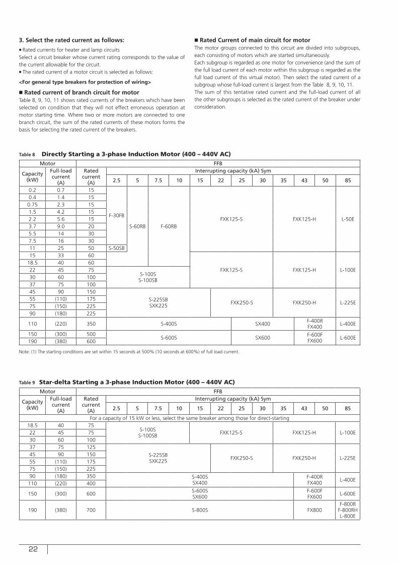
3. Select the rated current as follows:● Rated currents for heater and lamp circuitsSelect a circuit breaker whose current rating corresponds to the value of the current allowable for the circuit.● The rated current of a motor circuit is selected as follows:
<For general type breakers for protection of wiring>
■ Rated current of branch circuit for motorTable 8, 9, 10, 11 shows rated currents of the breakers which have been selected on condition that they will not effect erroneous operation at motor starting time. Where two or more motors are connected to one branch circuit, the sum of the rated currents of these motors forms the basis for selecting the rated current of the breakers.
■ Rated Current of main circuit for motorThe motor groups connected to this circuit are divided into subgroups, each consisting of motors which are started simultaneously.Each subgroup is regarded as one motor for convenience (and the sum of the full load current of each motor within this subgroup is regarded as the full load current of this virtual motor). Then select the rated current of a subgroup whose full-load current is largest from the Table 8, 9, 10, 11.The sum of this tentative rated current and the full-load current of all the other subgroups is selected as the rated current of the breaker under consideration.
Table 8 Directly Starting a 3-phase Induction Motor (400 – 440V AC)
Table 9 Star-delta Starting a 3-phase Induction Motor (400 – 440V AC)
Motor FFB
Capacity (kW)
Full-load current
(A)
Rated current
(A)
Interrupting capacity (kA) Sym
2.5 5 7.5 10 15 22 25 30 35 43 50 85
0.2 0.7 15
F-30FB
S-60RB F-60RBFXK125-S FXK125-H L-50E
0.4 1.4 150.75 2.3 151.5 4.2 152.2 5.6 153.7 9.0 205.5 14 307.5 16 3011 25 50 S-50SB15 33 60
FXK125-S FXK125-H L-100E18.5 40 6022 45 75
S-100SS-100SB30 60 100
37 75 10045 90 150
S-225SBSXK225 FXK250-S FXK250-H L-225E
55 (110) 17575 (150) 22590 (180) 225
110 (220) 350 S-400S SX400 F-400RFX400 L-400E
150 (300) 500S-600S SX600 F-600F
FX600 L-600E190 (380) 600
Motor FFB
Capacity (kW)
Full-load current
(A)
Rated current
(A)
Interrupting capacity (kA) Sym
2.5 5 7.5 10 15 22 25 30 35 43 50 85
For a capacity of 15 kW or less, select the same breaker among those for direct-starting18.5 40 75
S-100SS-100SB FXK125-S FXK125-H L-100E22 45 75
30 60 10037 75 125
S-225SBSXK225 FXK250-S FXK250-H L-225E
45 90 15055 (110) 17575 (150) 22590 (180) 350 S-400S
SX400F-400RFX400 L-400E
110 (220) 400
150 (300) 600 S-600SSX600
F-600FFX600 L-600E
190 (380) 700 S-800S FX800F-800R
F-800RHL-800E
Note: (1) The starting conditions are set within 15 seconds at 500% (10 seconds at 600%) of full load current.
23
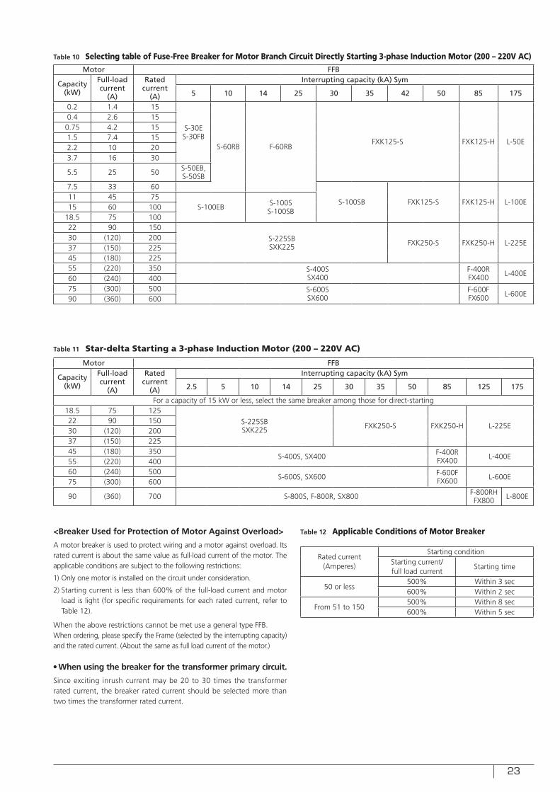
Table 10 Selecting table of Fuse-Free Breaker for Motor Branch Circuit Directly Starting 3-phase Induction Motor (200 – 220V AC)
Table 11 Star-delta Starting a 3-phase Induction Motor (200 – 220V AC)
Table 12 Applicable Conditions of Motor Breaker
Motor FFB
Capacity (kW)
Full-load current
(A)
Rated current
(A)
Interrupting capacity (kA) Sym
5 10 14 25 30 35 42 50 85 175
0.2 1.4 15
S-30ES-30FB
S-60RB F-60RBFXK125-S FXK125-H L-50E
0.4 2.6 150.75 4.2 151.5 7.4 152.2 10 203.7 16 30
5.5 25 50 S-50EB, S-50SB
7.5 33 60
S-100SB FXK125-S FXK125-H L-100E11 45 75
S-100EB S-100SS-100SB15 60 100
18.5 75 10022 90 150
S-225SBSXK225 FXK250-S FXK250-H L-225E
30 (120) 20037 (150) 22545 (180) 22555 (220) 350 S-400S
SX400F-400RFX400 L-400E
60 (240) 40075 (300) 500 S-600S
SX600F-600FFX600 L-600E
90 (360) 600
Motor FFB
Capacity (kW)
Full-load current
(A)
Rated current
(A)
Interrupting capacity (kA) Sym
2.5 5 10 14 25 30 35 50 85 125 175
For a capacity of 15 kW or less, select the same breaker among those for direct-starting18.5 75 125
S-225SBSXK225 FXK250-S FXK250-H L-225E
22 90 15030 (120) 20037 (150) 22545 (180) 350
S-400S, SX400 F-400RFX400 L-400E
55 (220) 40060 (240) 500
S-600S, SX600 F-600FFX600 L-600E
75 (300) 600
90 (360) 700 S-800S, F-800R, SX800 F-800RHFX800 L-800E
<Breaker Used for Protection of Motor Against Overload>
A motor breaker is used to protect wiring and a motor against overload. Its rated current is about the same value as full-load current of the motor. The applicable conditions are subject to the following restrictions:
1) Only one motor is installed on the circuit under consideration.
2) Starting current is less than 600% of the full-load current and motor load is light (for specific requirements for each rated current, refer to Table 12).
When the above restrictions cannot be met use a general type FFB.When ordering, please specify the Frame (selected by the interrupting capacity) and the rated current. (About the same as full load current of the motor.)
● When using the breaker for the transformer primary circuit.
Since exciting inrush current may be 20 to 30 times the transformer rated current, the breaker rated current should be selected more than two times the transformer rated current.
Rated current (Amperes)
Starting conditionStarting current/full load current
Starting time
50 or less500% Within 3 sec600% Within 2 sec
From 51 to 150500% Within 8 sec600% Within 5 sec
24
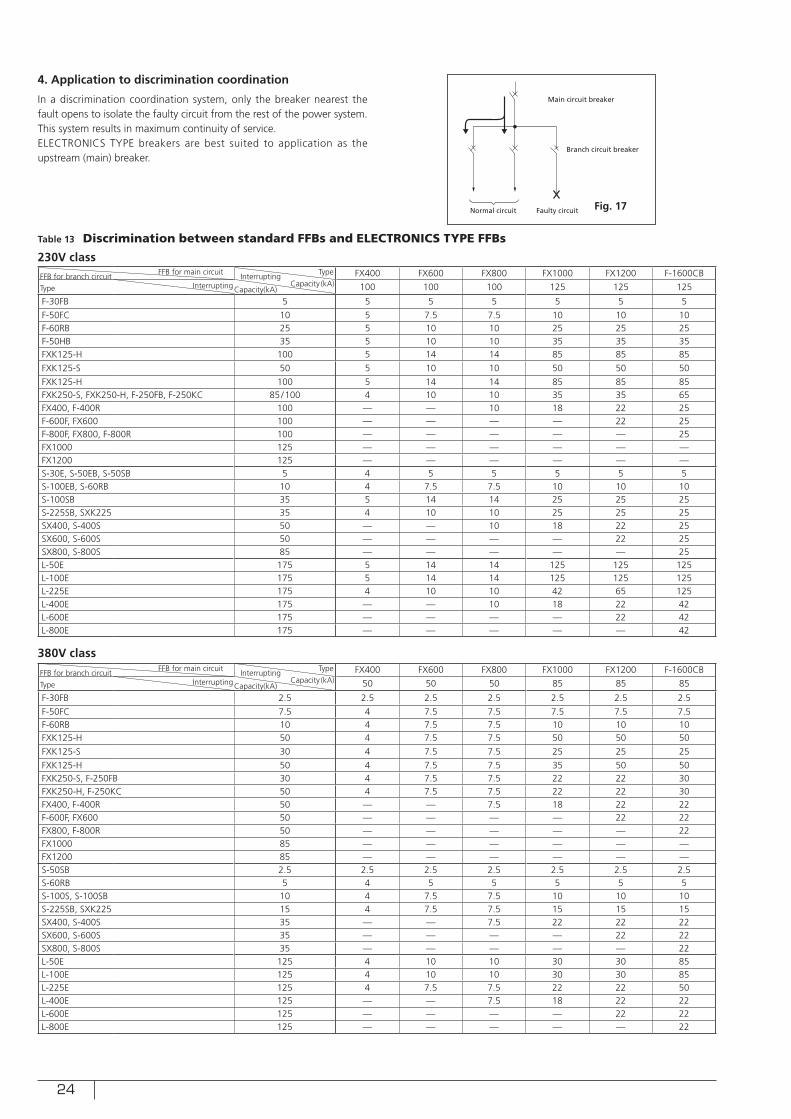
4. Application to discrimination coordination
In a discrimination coordination system, only the breaker nearest the fault opens to isolate the faulty circuit from the rest of the power system.This system results in maximum continuity of service.ELECTRONICS TYPE breakers are best suited to application as the upstream (main) breaker.
Table 13 Discrimination between standard FFBs and ELECTRONICS TYPE FFBs
Normal circuit
Main circuit breaker
Branch circuit breaker
Faulty circuit
FFB for branch circuit FFB for main circuit
Interrupting Type FX400 FX600 FX800 FX1000 FX1200 F-1600CB
Type Interrupting Capacity(kA) Capacity (kA) 100 100 100 125 125 125
F-30FB 5 5 5 5 5 5 5
F-50FC 10 5 7.5 7.5 10 10 10F-60RB 25 5 10 10 25 25 25F-50HB 35 5 10 10 35 35 35FXK125-H 100 5 14 14 85 85 85
FXK125-S 50 5 10 10 50 50 50
FXK125-H 100 5 14 14 85 85 85FXK250-S, FXK250-H, F-250FB, F-250KC 85/100 4 10 10 35 35 65FX400, F-400R 100 — — 10 18 22 25F-600F, FX600 100 — — — — 22 25F-800F, FX800, F-800R 100 — — — — — 25FX1000 125 — — — — — —FX1200 125 — — — — — —S-30E, S-50EB, S-50SB 5 4 5 5 5 5 5S-100EB, S-60RB 10 4 7.5 7.5 10 10 10S-100SB 35 5 14 14 25 25 25S-225SB, SXK225 35 4 10 10 25 25 25SX400, S-400S 50 — — 10 18 22 25SX600, S-600S 50 — — — — 22 25SX800, S-800S 85 — — — — — 25L-50E 175 5 14 14 125 125 125L-100E 175 5 14 14 125 125 125L-225E 175 4 10 10 42 65 125L-400E 175 — — 10 18 22 42L-600E 175 — — — — 22 42L-800E 175 — — — — — 42
FFB for branch circuit FFB for main circuit
Interrupting Type FX400 FX600 FX800 FX1000 FX1200 F-1600CB
Type Interrupting Capacity(kA) Capacity (kA) 50 50 50 85 85 85
F-30FB 2.5 2.5 2.5 2.5 2.5 2.5 2.5
F-50FC 7.5 4 7.5 7.5 7.5 7.5 7.5F-60RB 10 4 7.5 7.5 10 10 10FXK125-H 50 4 7.5 7.5 50 50 50
FXK125-S 30 4 7.5 7.5 25 25 25
FXK125-H 50 4 7.5 7.5 35 50 50FXK250-S, F-250FB 30 4 7.5 7.5 22 22 30FXK250-H, F-250KC 50 4 7.5 7.5 22 22 30FX400, F-400R 50 — — 7.5 18 22 22F-600F, FX600 50 — — — — 22 22FX800, F-800R 50 — — — — — 22FX1000 85 — — — — — —FX1200 85 — — — — — —S-50SB 2.5 2.5 2.5 2.5 2.5 2.5 2.5S-60RB 5 4 5 5 5 5 5S-100S, S-100SB 10 4 7.5 7.5 10 10 10S-225SB, SXK225 15 4 7.5 7.5 15 15 15SX400, S-400S 35 — — 7.5 22 22 22SX600, S-600S 35 — — — — 22 22SX800, S-800S 35 — — — — — 22L-50E 125 4 10 10 30 30 85L-100E 125 4 10 10 30 30 85L-225E 125 4 7.5 7.5 22 22 50L-400E 125 — — 7.5 18 22 22L-600E 125 — — — — 22 22L-800E 125 — — — — — 22
230V class
380V class
Fig. 17
25
ACCESSORIES
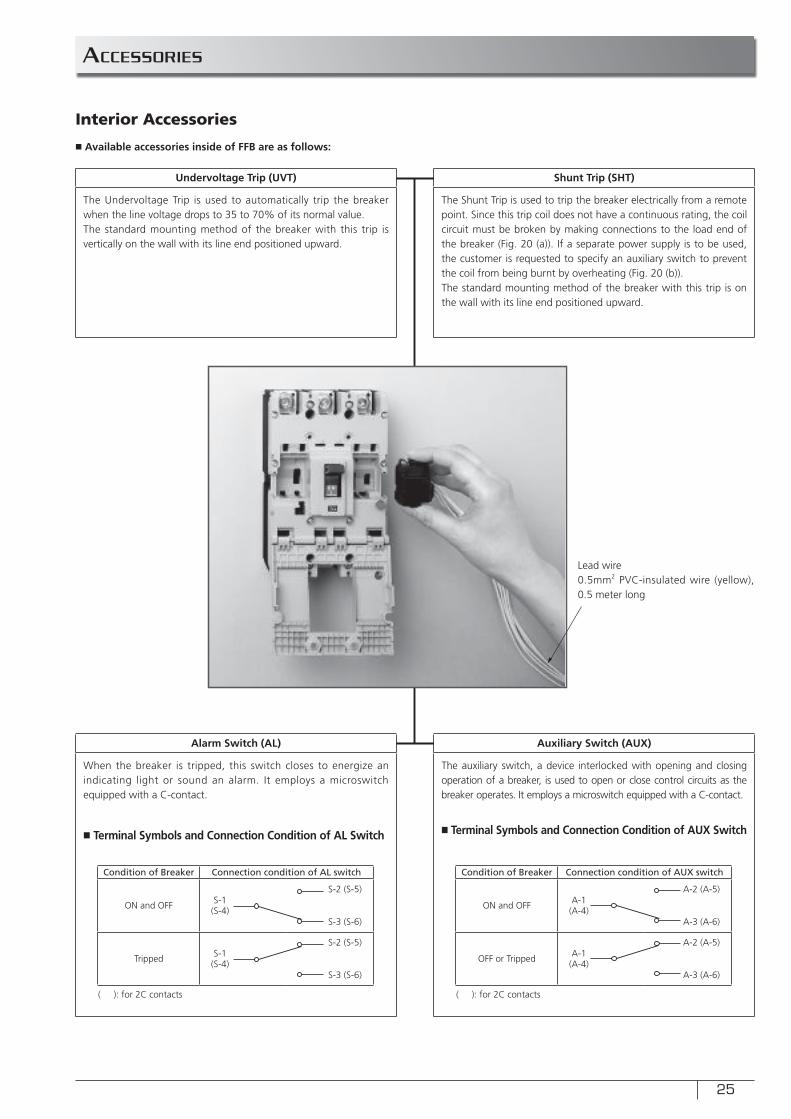
■ Available accessories inside of FFB are as follows:
Interior Accessories
Undervoltage Trip (UVT)
The Undervoltage Trip is used to automatically trip the breaker when the line voltage drops to 35 to 70% of its normal value.The standard mounting method of the breaker with this trip is vertically on the wall with its line end positioned upward.
Alarm Switch (AL)
When the breaker is tripped, this switch closes to energize an indicating light or sound an alarm. It employs a microswitch equipped with a C-contact.
■ Terminal Symbols and Connection Condition of AL Switch
Shunt Trip (SHT)
The Shunt Trip is used to trip the breaker electrically from a remote point. Since this trip coil does not have a continuous rating, the coil circuit must be broken by making connections to the load end of the breaker (Fig. 20 (a)). If a separate power supply is to be used, the customer is requested to specify an auxiliary switch to prevent the coil from being burnt by overheating (Fig. 20 (b)).The standard mounting method of the breaker with this trip is on the wall with its line end positioned upward.
Auxiliary Switch (AUX)
The auxiliary switch, a device interlocked with opening and closing operation of a breaker, is used to open or close control circuits as the breaker operates. It employs a microswitch equipped with a C-contact.
■ Terminal Symbols and Connection Condition of AUX Switch
Lead wire0.5mm2 PVC-insulated wire (yellow), 0.5 meter long
Condition of Breaker Connection condition of AL switch
ON and OFF S-1(S-4)
S-2 (S-5)
S-3 (S-6)
Tripped S-1(S-4)
S-2 (S-5)
S-3 (S-6)
Condition of Breaker Connection condition of AUX switch
ON and OFF A-1(A-4)
A-2 (A-5)
A-3 (A-6)
OFF or Tripped A-1(A-4)
A-2 (A-5)
A-3 (A-6)
( ): for 2C contacts ( ): for 2C contacts
26
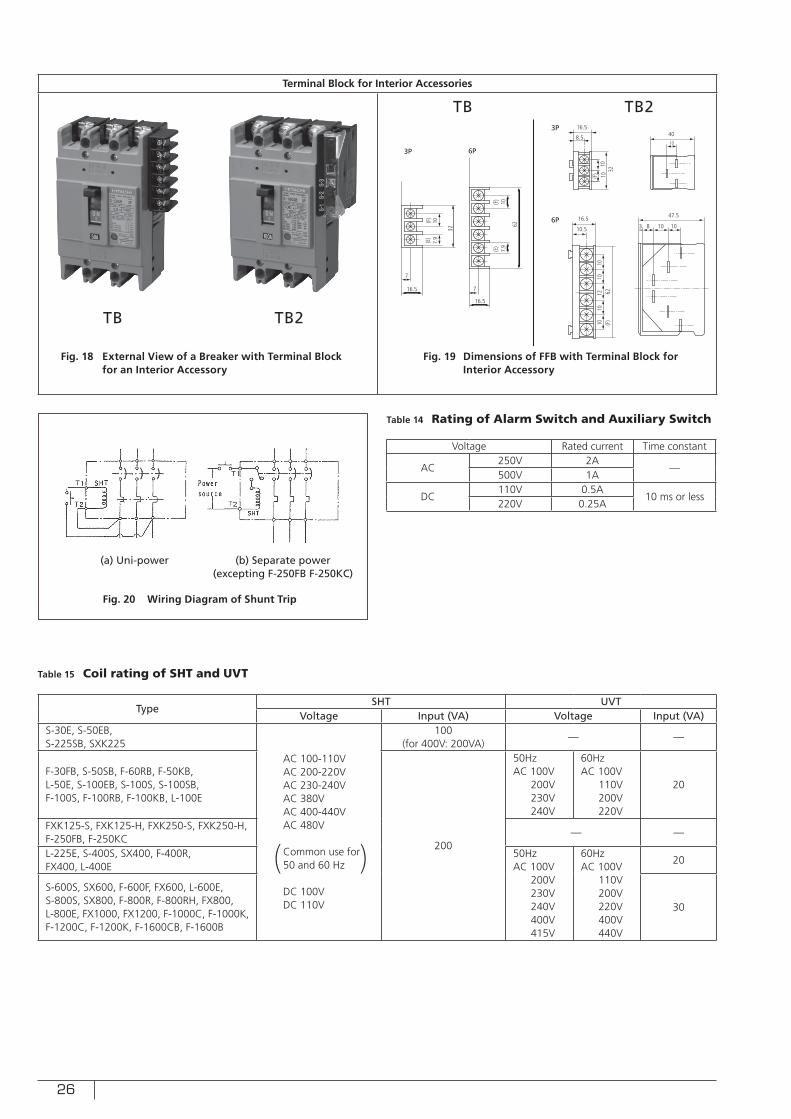
Terminal Block for Interior Accessories
Fig. 18 External View of a Breaker with Terminal Block for an Interior Accessory
Fig. 19 Dimensions of FFB with Terminal Block for Interior Accessory
TB TB2
TB TB2
32
(F)
107.9
(E)
7
16.5
(F)
10
62
(E)
7.9
16.5
7
16.5
8.54010
47.5
10108316.5
10.5
1010
1210
1062
(F)
3210
10(F)
3P 6P
3P
6P
Fig. 20 Wiring Diagram of Shunt Trip
Table 14 Rating of Alarm Switch and Auxiliary Switch
Table 15 Coil rating of SHT and UVT
Voltage Rated current Time constant
AC250V 2A
—500V 1A
DC110V 0.5A
10 ms or less220V 0.25A
TypeSHT UVT
Voltage Input (VA) Voltage Input (VA)S-30E, S-50EB, S-225SB, SXK225
AC 100-110VAC 200-220VAC 230-240VAC 380VAC 400-440VAC 480V
Common use for 50 and 60 Hz
DC 100VDC 110V
100(for 400V: 200VA)
— —
F-30FB, S-50SB, F-60RB, F-50KB,L-50E, S-100EB, S-100S, S-100SB,F-100S, F-100RB, F-100KB, L-100E
200
50HzAC 100V 200V 230V 240V
60HzAC 100V 110V 200V 220V
20
FXK125-S, FXK125-H, FXK250-S, FXK250-H, F-250FB, F-250KC
— —
L-225E, S-400S, SX400, F-400R,FX400, L-400E
50HzAC 100V 200V 230V 240V 400V 415V
60HzAC 100V 110V 200V 220V 400V 440V
20
S-600S, SX600, F-600F, FX600, L-600E, S-800S, SX800, F-800R, F-800RH, FX800, L-800E, FX1000, FX1200, F-1000C, F-1000K, F-1200C, F-1200K, F-1600CB, F-1600B
30
( )
(a) Uni-power (b) Separate power(excepting F-250FB F-250KC)
27
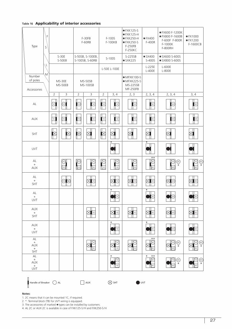
Table 16 Applicability of interior accessories
Type S
FF-30FBF-60RB
F-100S F-100KB
✶FXK125-S✶FXK125-H✶FXK250-H✶FXK250-S
F-250FBF-250KC
✶FX400✶F-400R
✶FX600 F-1200K✶FX800 F-1600B
F-600F F-800RF-1000KF-800RH
✶FX1000✶FX1200
F-1600CB
S-30E S-50EB
S-50SB, S-100EB,S-100SB, S-60RB
S-100SS-225SB
✶SXK225✶SX400✶S-400S
✶SX600 S-600S✶SX800 S-600S
L
L-50E L-100EL-225E L-400E
L-600EL-800E
Numberof poles
M
MS-30E MS-50EB
MS-50SB MS-100SB
✶MFXK100-S✶MFXK225-S
MS-225SBMF-250FBAccessories
2 3 2 3 2 3, 4 2, 3 2, 3, 4 2, 3, 4 3, 4
AL
AUX
SHT
UVT
AL+
AUX
AL+
SHT
AL+
UVT
AUX+
SHT
AUX+
UVT
AL+
AUX+
SHT
AL+
AUX+
UVT
1C
1C
1C 2C 2C 2C1C 1C
1C 1C 2C
1C 2C
1C 1C 2C1C 1C
1C
1C 2C 2C
1C
1C
1C
1C
1C
1C
1C
1C
1C
1C
1C
2C 2C
2C
1C 2C
1C
2C
1C
1C
2C
2C
1C
2C
1C
1C
1C
1C
1C 1C 2C 2C
1C 1C 2C 2C
1C
1C
1C
1C
1C
1C
2C
2C
1C
2C
1C 2C
2C 2C
2C 2C
2C
2C 1C
2C
2C
1C
2C
2C
2C1C
2C
Handle of Breaker AL AUX SHT UVT
Notes: 1. 2C means that it can be mounted 1C, if required.2. *: Terminal block (TB) for UVT wiring is equipped.3. The accessories of marked ✶ types can be installed by customers.4. AL 2C or AUX 2C is available in case of FXK125-S /H and FXK250-S /H
28
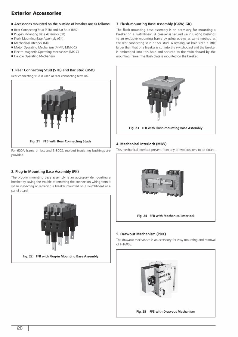
■ Accessories mounted on the outside of breaker are as follows:
■ Rear Connecting Stud (STB) and Bar Stud (BSD)■ Plug-in Mounting Base Assembly (PK)■ Flush Mounting Base Assembly (GK)■ Mechanical Interlock (MI)■ Motor Operating Mechanism (MMK, MMK-C)■ Electro-magnetic Operating Mechanism (MK-C)■ Handle Operating Mechanism
Exterior Accessories
1. Rear Connecting Stud (STB) and Bar Stud (BSD)
Rear connecting stud is used as rear connecting terminal.
2. Plug-in Mounting Base Assembly (PK)
The plug-in mounting base assembly is an accessory demounting a breaker by saving the trouble of removing the connection wiring from it when inspecting or replacing a breaker mounted on a switchboard or a panel board.
3. Flush-mounting Base Assembly (GKW, GK)
The flush-mounting base assembly is an accessory for mounting a breaker on a switchboard. A breaker is secured via insulating bushings to an exclusive mounting frame by using screws as same method as the rear connecting stud or bar stud. A rectangular hole sized a little larger than that of a breaker is cut into the switchboard and the breaker is embedded into this hole and secured to the switchboard by the mounting frame. The flush plate is mounted on the breaker.
4. Mechanical Interlock (MIW)
This mechanical interlock prevent from any of two breakers to be closed.
5. Drawout Mechanism (PDK)
The drawout mechanism is an accessory for easy mounting and removal of F-1600E.
For 600A frame or less and S-800S, molded insulating bushings are provided.
Fig. 21 FFB with Rear Connecting Studs
Fig. 23 FFB with Flush-mounting Base Assembly
Fig. 24 FFB with Mechanical Interlock
Fig. 25 FFB with Drawout Mechanism
Fig. 22 FFB with Plug-in Mounting Base Assembly
29
Fig. 27 Control Circuit of Motor Operating Mechanism
6. Motor Operating Mechanism (MMK-S)
• This mechanism is suitable to remote control a breaker by utilizing a motor.Since the control circuit is self holding type, the operation of this mechanism is completed by brief closing of push button switch contact. As soon as completing of operation, the control circuit is opened and the motor is stopped by instant operation of a limit switch.
• The manual operation is also available.
Fig. 26 Motor Operating Mechanism
Table 17 Standard Ratings of Motor Operated Mechcanism
Type MMK-S
Type of FFB
F series
3P 4P
FXK125-SFXK125-H
FX400 F-400R
F100KBF-250FBF-250KC
F-400R
L seriesL-50E
L-100EL-225EL-400E
L-50E L-100E
L-225EL-400E
S seriesS-225SBSXK225
SX400S-400S
— —
Max. operational current peak (A)
DC100—
DC110AC100 0.2
(0.6)0.3(0.9)
0.2(0.6)
0.3(0.9)AC110
AC200 0.1(0.3)
0.15(0.45)
0.1(0.3)
0.15(0.45)AC220
Power supply (VA) 500 100 50 100
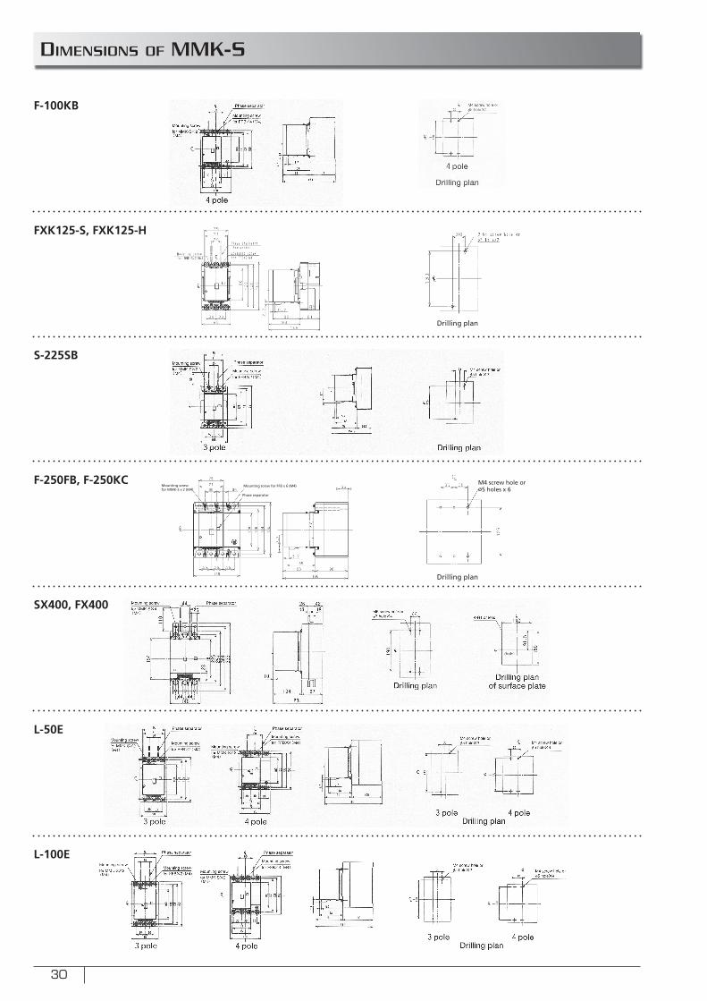
30
DIMENSIONS OF MMK-S
F-100KB
FXK125-S, FXK125-H
S-225SB
F-250FB, F-250KC
SX400, FX400
L-50E
L-100E
Drilling plan
Drilling plan
Mounting screw for MMK-S x 2 (M4)
Phase separator
Mounting screw for FFB x 6 (M4)M4 screw hole or ø5 holes x 6
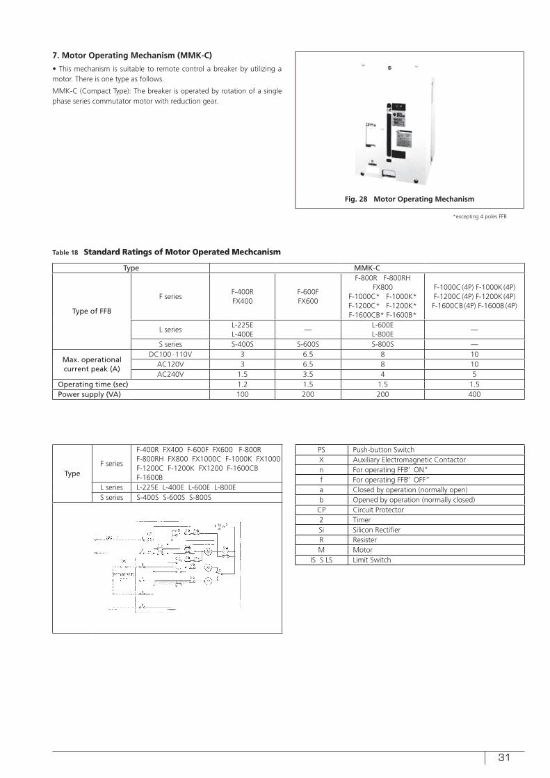
31
7. Motor Operating Mechanism (MMK-C)
• This mechanism is suitable to remote control a breaker by utilizing a motor. There is one type as follows.
MMK-C (Compact Type): The breaker is operated by rotation of a single phase series commutator motor with reduction gear.
Fig. 28 Motor Operating Mechanism
Table 18 Standard Ratings of Motor Operated Mechcanism
Type MMK-C
Type of FFB
F seriesF-400RFX400
F-600FFX600
F-800R F-800RHFX800
F-1000C* F-1000K*F-1200C* F-1200K*F-1600CB* F-1600B*
F-1000C(4P) F-1000K(4P)F-1200C(4P) F-1200K(4P)F-1600CB(4P) F-1600B (4P)
L seriesL-225EL-400E
—L-600E L-800E
—
S series S-400S S-600S S-800S —
Max. operational current peak (A)
DC100∙110V 3 6.5 8 10AC120V 3 6.5 8 10AC240V 1.5 3.5 4 5
Operating time (sec) 1.2 1.5 1.5 1.5Power supply (VA) 100 200 200 400
TypeF series
F-400R FX400 F-600F FX600 F-800R F-800RH FX800 FX1000C F-1000K FX1000 F-1200C F-1200K FX1200 F-1600CB F-1600B
L series L-225E L-400E L-600E L-800ES series S-400S S-600S S-800S
PS Push-button SwitchX Auxiliary Electromagnetic Contactorn For operating FFB “ ON”f For operating FFB “ OFF”a Closed by operation (normally open)b Opened by operation (normally closed)
CP Circuit Protector2 TimerSi Silicon RectifierR ResisterM Motor
IS S LS Limit Switch
*excepting 4 poles FFB
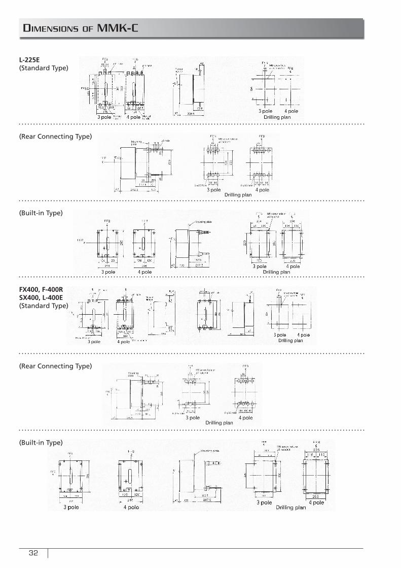
32
DIMENSIONS OF MMK-C
L-225E(Standard Type)
(Rear Connecting Type)
(Built-in Type)
(Rear Connecting Type)
FX400, F-400RSX400, L-400E(Standard Type)
(Built-in Type)
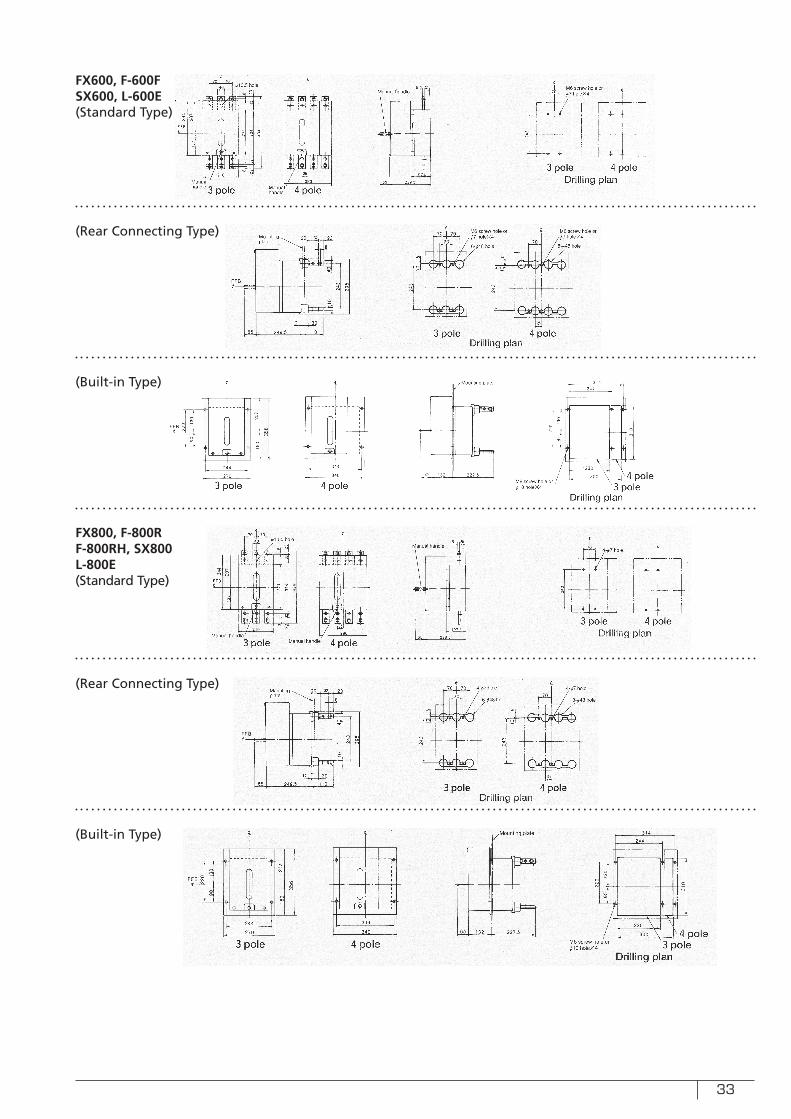
33
FX600, F-600FSX600, L-600E(Standard Type)
(Rear Connecting Type)
(Built-in Type)
(Rear Connecting Type)
FX800, F-800RF-800RH, SX800L-800E(Standard Type)
(Built-in Type)
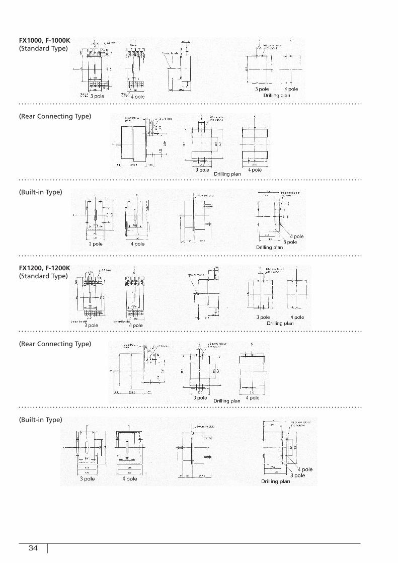
34
(Rear Connecting Type)
(Built-in Type)
(Rear Connecting Type)
FX1000, F-1000K(Standard Type)
FX1200, F-1200K(Standard Type)
(Built-in Type)
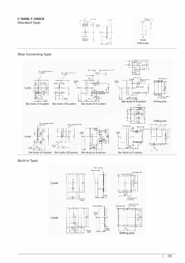
35
F-1600B, F-1600CB(Standard Type)
(Rear Connecting Type)
(Built-in Type)
ø13.5 holes
Manual handle
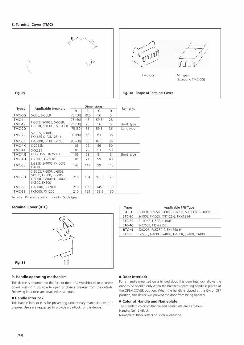
36
8. Terminal Cover (TMC)
Terminal Cover (BTC)
9. Handle operating mechanism
This device is mounted on the face or door of a switchboard or a control board, making it possible to open or close a breaker from the outside. Following interlocks are attached as standard.
■ Handle InterlockThis handle interlocks is for preventing unnecessary manipulations of a breaker. Users are requested to provide a padlock for this device.
■ Door InterlockFor a handle mounted on a hinged door, this door interlock allows the door to be opened only when the breaker’s operating handle is placed at the OPEN COVER position. When the handle is placed at the ON or OFF position, this device will prevent the door from being opened.
■ Color of Handle and NameplateThe standard colors of handle and nameplate are as follows:Handle: No1.5 (Black)Nameplate: Black letters on silver aventurine
Fig. 29
Fig. 31
Fig. 30 Shape of Terminal Cover
D
AB
C
TMC-0G All Types(Excepting TMC-0G)
Types Applicable breakersDimensions
RemarksA B C D
TMC-0G S-30E, S-50EB 75 (50) 19.5 56 5TMC-1
F-30FB, S-50SB, S-60SB, F-60RB, S-100EB, S-100SB
75 (50) 48 59.5 28TMC-1S 75 (50) 25 56 5 Short typeTMC-2D 75 (50 56 59.5 36 Long type
TMC-2C S-100S, F-100S, FXK125-S, FXK125-H 90 (60) 63 63 36
TMC-3C F-100KB, L-50E, L-100E 90 (60) 56 85.5 36TMC-4K S-225SB 105 79 56 50TMC-4J SXK225
FXK250-S, FX-250-H105 79 53 50
TMC-4JS 105 28 51 5 Short typeTMC-4H F-250FB, F-250KC 105 71 99 40
TMC-5B L-225E, S-400S, F-400FB, L-400E 147 147 99 110
TMC-5D
S-600S, F-600F, L-600E, SX600, FX600, S-800S, F-800R, F-800RH, L-800E, SX800, FX800
210 154 91.5 129
TMC-6 F-1000K, F-1200K 210 159 145 130TMC-6B FX1000, FX1200 210 159 138.5 130
Types Applicable FFB TypeBTC-1 F-30FB, S-50SB, S-60RB, F-60RB, S-100EB, S-100SB
BTC-2C S-100S, F-100S, FXK125-S, FXK125-HBTC-3C F-100KB, L-50E, L-100EBTC-4G S-225SB, MS-225SBBTC-4J SXK225, FXK250-S, FXK250-HBTC-5B L-225E, L-400E, S-400S, F-400R, SX400, FX400
Remarks Dimensions with ( ) are for 2-pole types
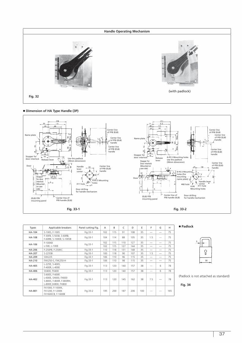
37
■ Dimension of HA Type Handle (3P)
Handle Operating Mechanism
Fig. 32
(with padlock)
Center line of FFB (ELB)handle
Stopper for door interlock Use the padlock
(30mm dimension)
(ELB) FFB mounting panel
Stopper for door interlock(Mounted on case side)
Door
Release lever
Name plate
Max
. AM
ax. B
Door drillingfor handle mechanism
Center line of FFB handle (ELB)
Fig. 33-1 Fig. 33-2
Center line of FFB (ELB)handle
Center line of FFB (ELB)
Center line of FFB (ELB)handle
Handle lever center
ø11 hole
4-ø5.5 Mountingholes
Center line of FFB (ELB)handle Stopper for
door interlock
Stopper for Door interlock(Mounted on case side)
Door
Releaselever
Name plate Max
. AM
ax. B
Door drillingfor handle mechanism
Center line of FFB (ELB)handle
Center line of FFB (ELB)
Center line of FFB (ELB)handle
Handle lever centerø60 hole
ø11 hole
4-ø5.5 Mountingholes (For mounting name plate)
4-ø6 Mounting holes
(ELB) FFB mounting panel
Center line of FFB handle (ELB)
4-ø5.5 Mounting holesUse the padlock(30mm dimension)
Types Applicable breakers Panel cutting Fig. A B C D E F G H
HA-104 S-100S, F-100S Fig.33-1 102 115 91 108 35 — — 75
HA-108F-30FB, S-50SB, S-60RB, F-60RB, S-100EB, S-100SB
Fig.33-1 104 114 88 105 35 1.5 — 75
HA-106F-100KBL-50E, L-100E
Fig.33-1102 115 110 127 35 — — 75
102 115 127 144 35 — — 75
HA-206 F-250FB, F-250KC Fig.33-1 110 118 131 148 35 — — 75
HA-207 S-225SB Fig.33-1 100 118 90 107 35 1.5 — 75
HA-209 SXK225 Fig.33-1 106 110 96 115 35 — — 75
HA-210 FXK250-S, FXK250-H Fig.33-1 106 110 98 115 35 — — 75
HA-405L-225E, S-400S,F-400R, L-400E
Fig.33-1 113 120 140 157 38 — 6 78
HA-406 SX400, FX400 Fig.33-1 113 120 140 157 38 — 6 78
HA-402
S-600S, F-600F,L-600E, SX600, FX600S-800S, F-800R, F-800RH,L-800E,SX800, FX800
Fig.33-1 113 120 145 162 38 7.5 — 78
HA-801FX1000, F-1000K,FX1200, F-1200KFX1600CB, F-1600B
Fig.33-2 195 200 187 206 100 — — 165
■ Padlock
(Padlock is not attached as standard)
5
30
Fig. 34
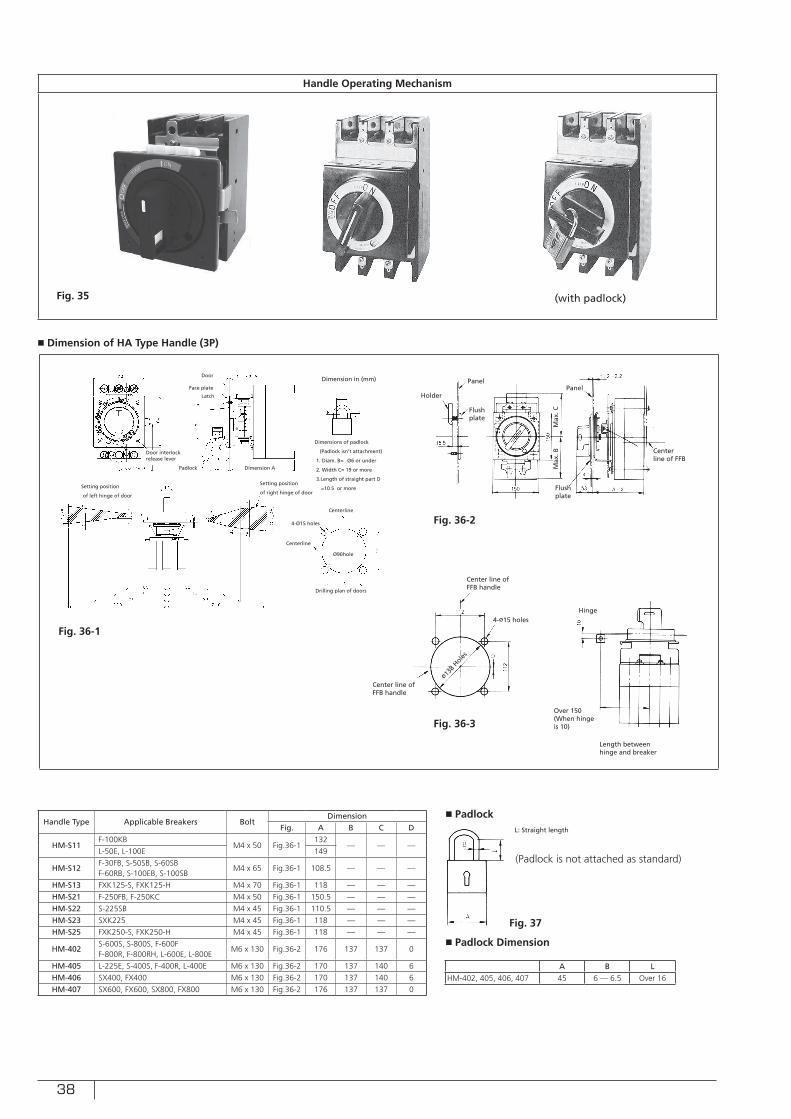
38
■ Dimension of HA Type Handle (3P)
Handle Operating Mechanism
Fig. 35 (with padlock)
Handle Type Applicable Breakers BoltDimension
Fig. A B C D
HM-S11F-100KB
M4 x 50 Fig.36-1132
— — —L-50E, L-100E 149
HM-S12F-30FB, S-50SB, S-60SBF-60RB, S-100EB, S-100SB
M4 x 65 Fig.36-1 108.5 — — —
HM-S13 FXK125-S, FXK125-H M4 x 70 Fig.36-1 118 — — —
HM-S21 F-250FB, F-250KC M4 x 50 Fig.36-1 150.5 — — —
HM-S22 S-225SB M4 x 45 Fig.36-1 110.5 — — —
HM-S23 SXK225 M4 x 45 Fig.36-1 118 — — —
HM-S25 FXK250-S, FXK250-H M4 x 45 Fig.36-1 118 — — —
HM-402S-600S, S-800S, F-600FF-800R, F-800RH, L-600E, L-800E
M6 x 130 Fig.36-2 176 137 137 0
HM-405 L-225E, S-400S, F-400R, L-400E M6 x 130 Fig.36-2 170 137 140 6
HM-406 SX400, FX400 M6 x 130 Fig.36-2 170 137 140 6
HM-407 SX600, FX600, SX800, FX800 M6 x 130 Fig.36-2 176 137 137 0
■ Padlock
■ Padlock Dimension
(Padlock is not attached as standard)
Fig. 37
Dimensions of padlock
(Padlock isn’t attachment)
1. Diam. B= Ø6 or under
2. Width C= 19 or more
3.Length of straight part D
=10.5 or more
Latch
Face plate
Door
Padlock
Door interlock release lever
Setting position
of right hinge of door Setting position
of left hinge of door
Centerline
Drilling plan of doors
4-Ø15 holes
Ø90hole
Dimension A
Dimension in (mm)
Centerline
Center line of FFB handle
Fig. 36-1
ø
PanelPanel
Max
. CM
ax. B Center
line of FFB
Flush plate
Flush plate
Holder
4-ø15 holes
Center line of FFB handle
ø138
Holes
Hinge
Fig. 36-2
Fig. 36-3Over 150(When hingeis 10)
Length between hinge and breaker
L: Straight length
A B LHM-402, 405, 406, 407 45 6 — 6.5 Over 16
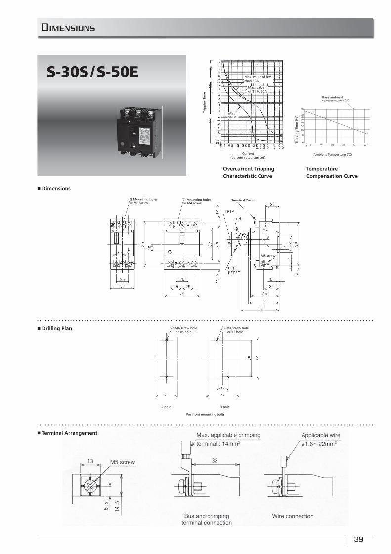
39
DIMENSIONS
■ Dimensions
■ Drilling Plan
300
200180160140120
100
80
60-5 0 10 20 30 40 50
S-30S/S-50E
Sec.
Min
.H
r.
Ambient Temperture (ºC)Current (percent rated current)
Trip
pin
g T
ime
Trip
pin
g T
ime
(%)
Overcurrent Tripping Characteristic Curve
Temperature Compensation Curve
Terminal Cover(2) Mounting holes for M4 screw
2-M4 screw hole or ø5 hole
2-M4 screw hole or ø5 hole
2 pole 3 pole
Base ambient temperature 40ºC
Max. value of less than 30A
Max. value of 31 to 50A
Min. value
(2) Mounting holes for M4 screw
For front mounting bolts
■ Terminal Arrangement
M5 screw
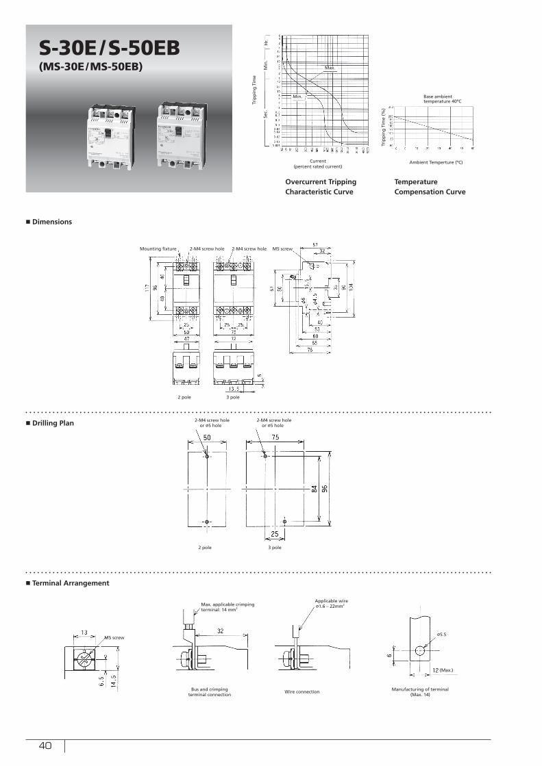
40
■ Dimensions
■ Drilling Plan
■ Terminal Arrangement
S-30E/S-50EB(MS-30E/MS-50EB)
Min.
Max.
Sec.
Min
.H
r.
Ambient Temperture (ºC)Current (percent rated current)
Trip
pin
g T
ime
Trip
pin
g T
ime
(%)
Overcurrent Tripping Characteristic Curve
Temperature Compensation Curve
Mounting fixture 2-M4 screw hole 2-M4 screw hole M5 screw
2 pole 3 pole
2-M4 screw hole or ø5 hole
2 pole 3 pole
M5 screw
Max. applicable crimpingterminal: 14 mm2
Bus and crimping terminal connection
Manufacturing of terminal (Max. 14)
Applicable wireø1.6 – 22mm2
Wire connection
Base ambient temperature 40ºC
2-M4 screw hole or ø5 hole
ø5.5
(Max.)
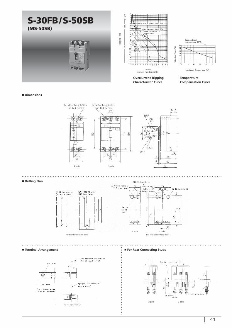
41
■ Dimensions
■ Drilling Plan
■ Terminal Arrangement ■ For Rear Connecting Studs
S-30FB/S-50SB(MS-50SB)
Min. value for AC
Min. value for DC
Max. value of less than 30A
Sec.
Min
.H
r.
Ambient Temperture (ºC)Current (percent rated current)
Trip
pin
g T
ime
(%)
Trip
pin
g T
ime
Overcurrent Tripping Characteristic Curve
Temperature Compensation Curve
2 pole 3 pole
Max. value of 31 to 50AMax. value for DC application
Base ambient temperature 40ºC
2 pole 3 pole
For front mounting bolts For rear connecting studs
2 pole 3 pole
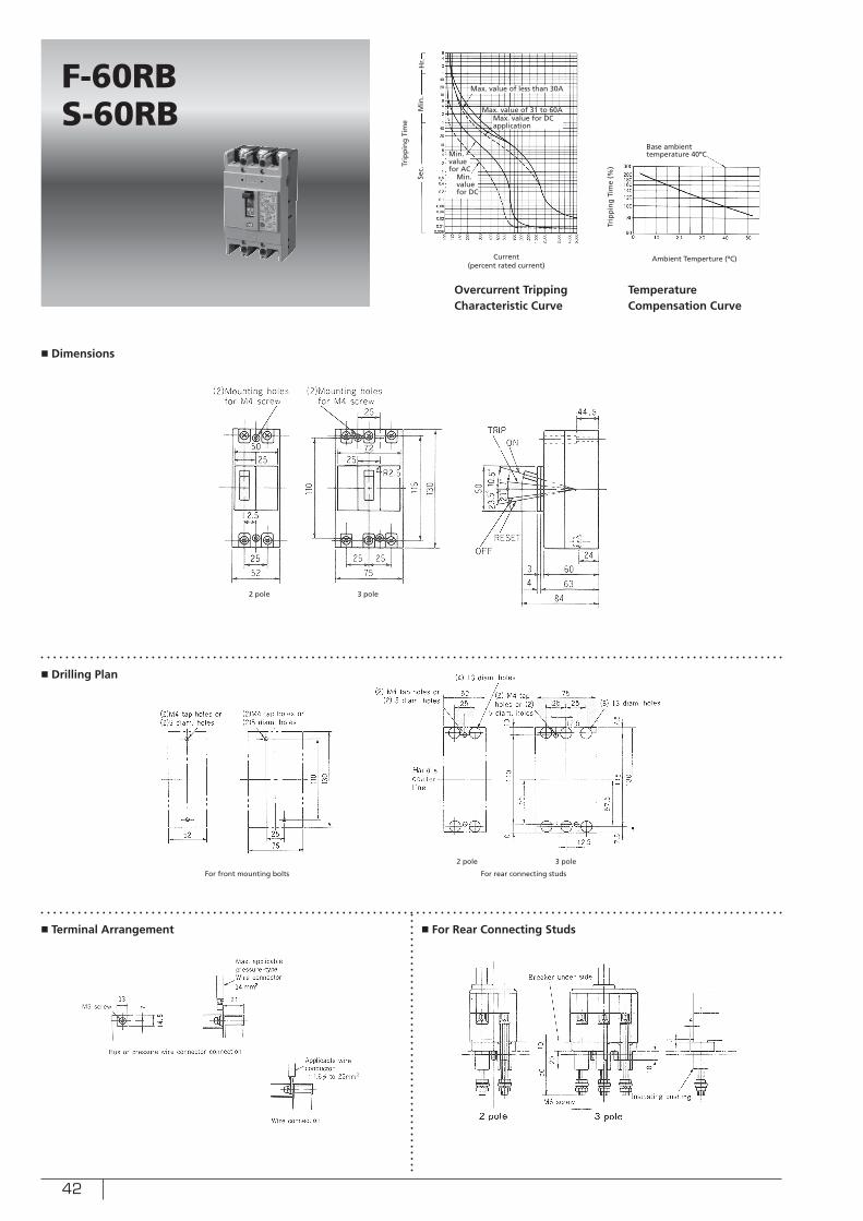
42
■ Dimensions
■ Drilling Plan
■ Terminal Arrangement ■ For Rear Connecting Studs
F-60RBS-60RB
Min. value for AC
Min. value for DC
Max. value of less than 30A
Sec.
Min
.H
r.
Ambient Temperture (ºC)Current (percent rated current)
Trip
pin
g T
ime
(%)Tr
ipp
ing
Tim
e
Overcurrent Tripping Characteristic Curve
Temperature Compensation Curve
Max. value of 31 to 60AMax. value for DC application
Base ambient temperature 40ºC
2 pole 3 pole
2 pole 3 pole
For front mounting bolts For rear connecting studs
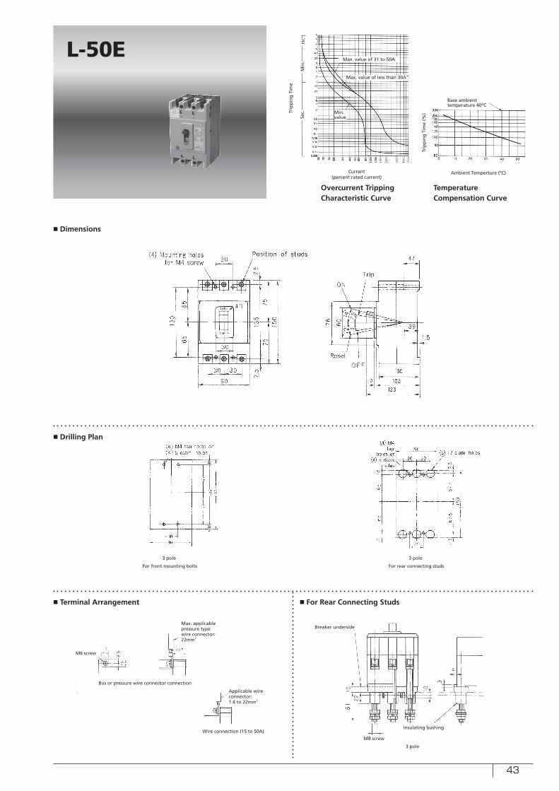
43
■ Dimensions
■ Drilling Plan
■ Terminal Arrangement ■ For Rear Connecting Studs
L-50E
Min. value
Max. value of less than 30A
Sec.
Min
.H
r.
Ambient Temperture (ºC)Current (percent rated current)
Trip
pin
g T
ime
(%)Tr
ipp
ing
Tim
e
Overcurrent Tripping Characteristic Curve
Temperature Compensation Curve
Max. value of 31 to 50A
Base ambient temperature 40ºC
3 pole3 pole
For front mounting bolts For rear connecting studs
3 pole
Max. applicable pressure typewire connector: 22mm2
Applicable wire connector: 1.6 to 22mm2
M6 screw
Bus or pressure wire connector connection
Wire connection (15 to 50A)
M8 screw
Breaker underside
Insulating bushing
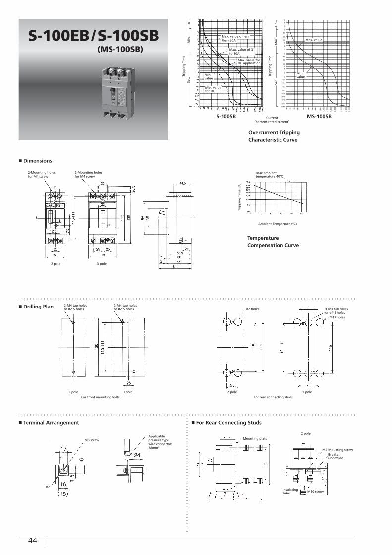
44
■ Dimensions
■ Drilling Plan
■ Terminal Arrangement ■ For Rear Connecting Studs
Min. value
Min. value
Min. value for DC
Max. value of less than 30A Max. value
Sec.
Sec.
Min
.
Min
.
Hr.
Hr.
Ambient Temperture (ºC)
Current (percent rated current)
Trip
pin
g T
ime
(%)
Trip
pin
g T
ime
Trip
pin
g T
ime
Overcurrent Tripping Characteristic Curve
Temperature Compensation Curve
Max. value of 31 to 50A
Max. value for DC application
Base ambient temperature 40ºC
S-100EB/S-100SB (MS-100SB)
S-100SB MS-100SB
2-Mounting holesfor M4 screw
2-Mounting holesfor M4 screw
2 pole 3 pole
2-M4 tap holesor ø2-5 holes
2-M4 tap holesor ø2-5 holes
2 pole 2 pole3 pole 3 pole
For front mounting bolts For rear connecting studs
4-M4 tap holesor ø4-5 holes
ø17 holes
ø2 holes
M8 screw
R2
Applicable pressure typewire connector: 38mm2
Mounting plate
M10 screwInsulatingtube
2 pole
M4 Mounting screwBreakerunderside
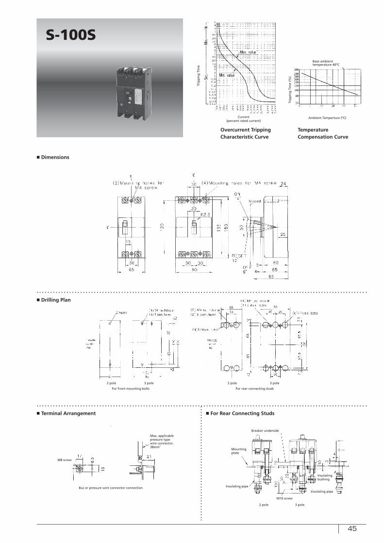
45
■ Dimensions
■ Drilling Plan
■ Terminal Arrangement ■ For Rear Connecting Studs
S-100S
Ambient Temperture (ºC)Current (percent rated current)
Trip
pin
g T
ime
(%)
Trip
pin
g T
ime
Overcurrent Tripping Characteristic Curve
Temperature Compensation Curve
Base ambient temperature 40ºC
2 pole 2 pole3 pole 3 pole
For front mounting bolts For rear connecting studs
M8 screw
Max. applicable pressure typewire connector: 38mm2
Bus or pressure wire connector connection
2 pole 3 pole
M10 screw
Breaker underside
Insulating bushing
Insulating pipe
Insulating pipe
Mounting plate
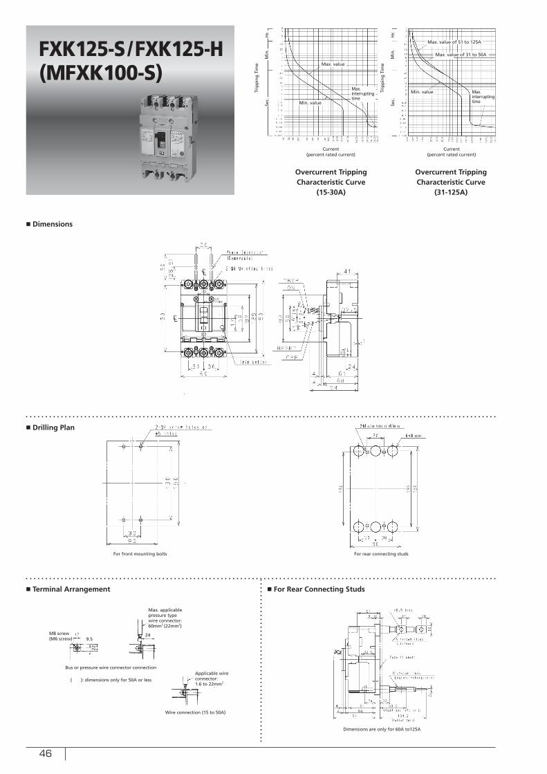
46
■ Dimensions
■ Drilling Plan
■ Terminal Arrangement ■ For Rear Connecting Studs
FXK125-S/FXK125-H(MFXK100-S)
22
249.5
For front mounting bolts For rear connecting studs
Max. applicable pressure typewire connector: 60mm2 (22mm2)
Applicable wire connector: 1.6 to 22mm2
M8 screw(M6 screw)
Bus or pressure wire connector connection
Wire connection (15 to 50A)
( ): dimensions only for 50A or less
Dimensions are only for 60A to125A
Max. value
Sec.
Sec.
Min
.
Min
.
Hr.
Hr.
Current (percent rated current)
Current (percent rated current)
Trip
pin
g T
ime
Trip
pin
g T
ime
Overcurrent Tripping Characteristic Curve
(15-30A)
Overcurrent Tripping Characteristic Curve
(31-125A)
Min. value
Max. interrupting time
Min. value Max. interrupting time
Max. value of 31 to 50A
Max. value of 51 to 125A
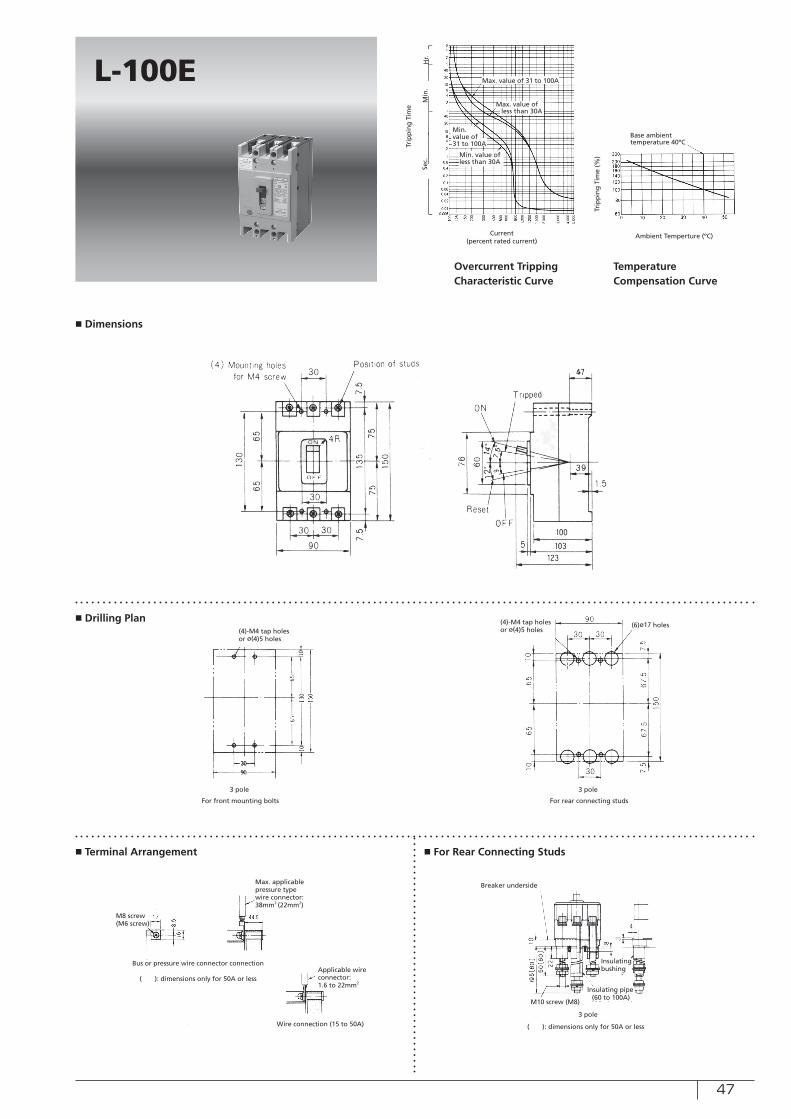
47
■ Dimensions
■ Drilling Plan
■ Terminal Arrangement ■ For Rear Connecting Studs
L-100EMax. value of less than 30A
Sec.
Min
.H
r.
Ambient Temperture (ºC)Current (percent rated current)
Trip
pin
g T
ime
(%)
Trip
pin
g T
ime
Overcurrent Tripping Characteristic Curve
Temperature Compensation Curve
Max. value of 31 to 100A
Base ambient temperature 40ºC
Min. value of less than 30A
Min. value of 31 to 100A
For front mounting bolts For rear connecting studs
Max. applicable pressure typewire connector: 38mm2 (22mm2)
Applicable wire connector: 1.6 to 22mm2
M8 screw(M6 screw)
Bus or pressure wire connector connection
Wire connection (15 to 50A)
( ): dimensions only for 50A or less
3 pole 3 pole
3 pole
M10 screw (M8)
Breaker underside
Insulating bushing
Insulating pipe
( ): dimensions only for 50A or less
(60 to 100A)
(4)-M4 tap holesor ø(4)5 holes
(4)-M4 tap holesor ø(4)5 holes
(6)ø17 holes
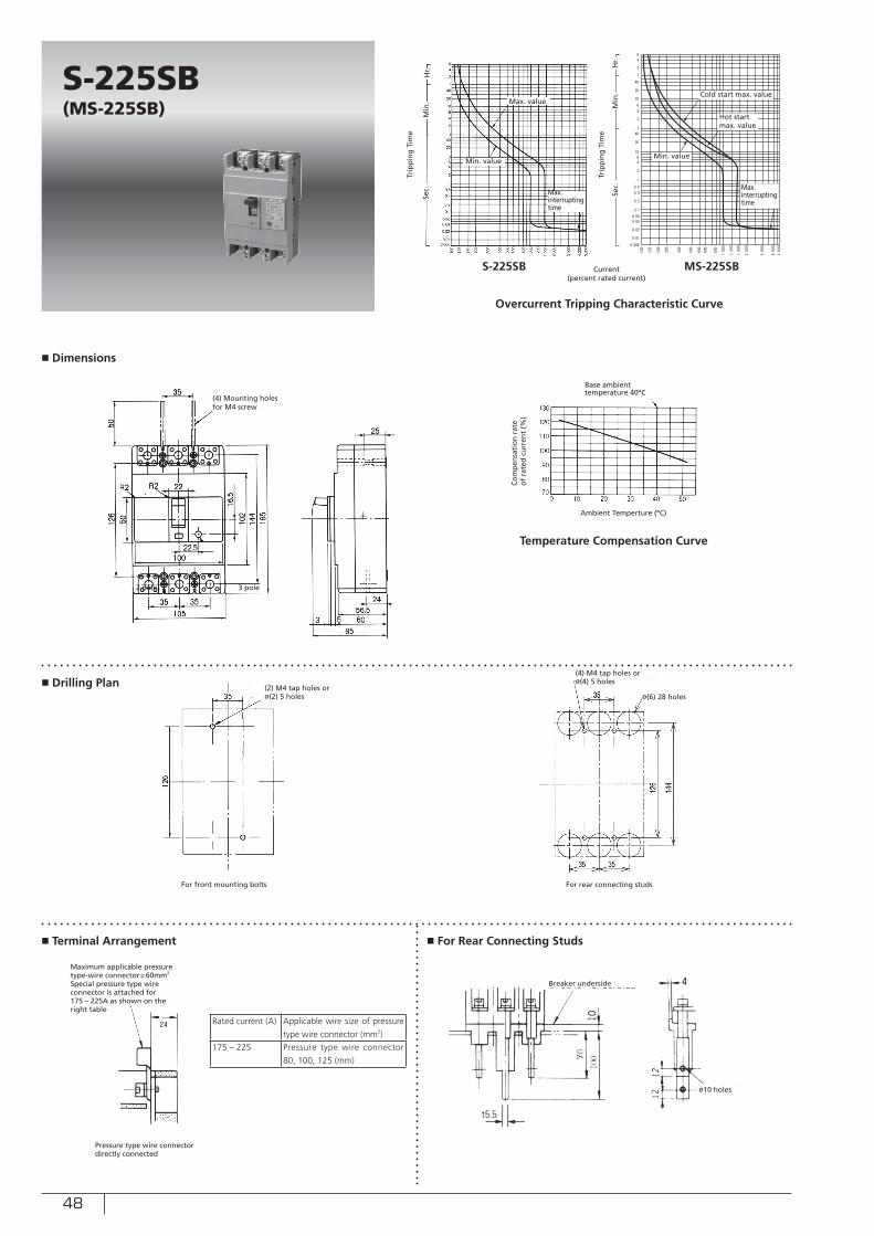
48
■ Dimensions
■ Drilling Plan
■ Terminal Arrangement ■ For Rear Connecting Studs
Min. value
Sec.
Min
.H
r.
Current (percent rated current)
Trip
pin
g T
ime
Trip
pin
g T
ime
Overcurrent Tripping Characteristic Curve
Max. value
S-225SB(MS-225SB)
S-225SB MS-225SB
(4) Mounting holesfor M4 screw
2 pole 3 pole
(2) M4 tap holes or ø(2) 5 holes
For front mounting bolts For rear connecting studs
Maximum applicable pressure type-wire connector=60mm2
Special pressure type wire connector is attached for 175 – 225A as shown on the right table
Max. interrupting time
(4) M4 tap holes or ø(4) 5 holes
ø(6) 28 holes
Pressure type wire connector directly connected
Rated current (A) Applicable wire size of pressure
type wire connector (mm2)
175 – 225 Pressure type wire connector
80, 100, 125 (mm)
Cold start max. value
Sec.
Min
.H
r.
Min. value
Max. interrupting time
Breaker underside
ø10 holes
Hot startmax. value
Ambient Temperture (ºC)
Temperature Compensation Curve
Base ambient temperature 40ºC
Co
mp
ensa
tio
n r
ate
of
rate
d c
urr
ent
(%)
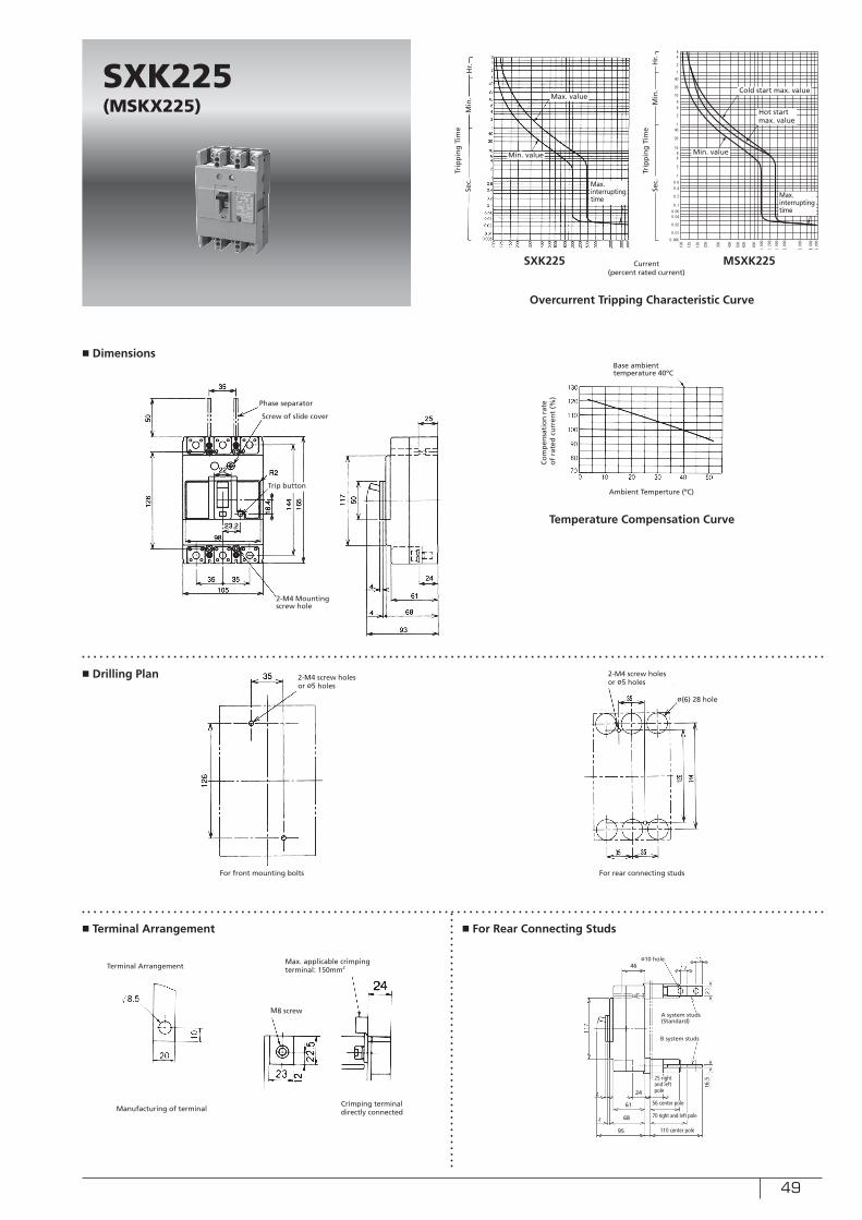
49
■ Dimensions
■ Drilling Plan
■ Terminal Arrangement ■ For Rear Connecting Studs
Min. value
Sec.
Sec.
Min
.
Min
.
Hr. H
r.
Ambient Temperture (ºC)
Current (percent rated current)
Trip
pin
g T
ime
Trip
pin
g T
ime
Overcurrent Tripping Characteristic Curve
Temperature Compensation Curve
Max. value
Base ambient temperature 40ºC
SXK225(MSKX225)
SXK225 MSXK225
2-M4 Mounting screw hole
2-M4 screw holes or ø5 holes
For front mounting bolts For rear connecting studs
Max. interrupting time
Min. value
Max. interrupting time
ø(6) 28 hole
Manufacturing of terminal
Phase separator
Screw of slide cover
Trip button
2-M4 screw holes or ø5 holes
Terminal ArrangementMax. applicable crimping terminal: 150mm2
Crimping terminal directly connected
M8 screw
ø10 hole46
A system studs(Standard)
B system studs
24
61
68
95
25 rightand left pole
56 center pole
70 right and left pole
110 center pole
t6.5
Hot startmax. value
Cold start max. value
Co
mp
ensa
tio
n r
ate
of
rate
d c
urr
ent
(%)
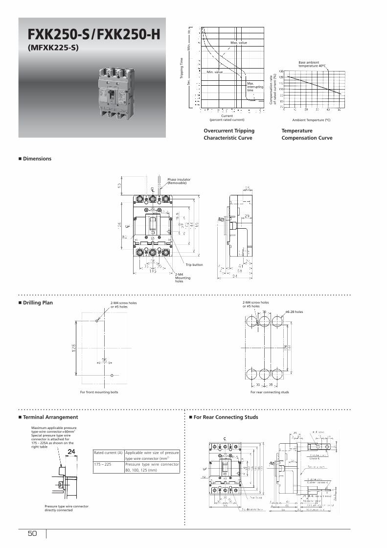
50
■ Dimensions
■ Drilling Plan
■ Terminal Arrangement ■ For Rear Connecting Studs
Min. value
Sec.
Min
.H
r.
Ambient Temperture (ºC)
Trip
pin
g T
ime
Max. value
Base ambient temperature 40ºC
FXK250-S /FXK250-H(MFXK225-S)
2-M4 Mounting holes
2-M4 screw holes or ø5 holes
For front mounting bolts For rear connecting studs
Max. interrupting time
ø6-28 holes
Phase insulator(Removable)
Trip button
2-M4 screw holes or ø5 holes
Current (percent rated current)
Overcurrent Tripping Characteristic Curve
Temperature Compensation Curve
Pressure type wire connector directly connected
Rated current (A) Applicable wire size of pressure
type wire connector (mm2)
175 – 225 Pressure type wire connector
80, 100, 125 (mm)
Maximum applicable pressure type-wire connector=60mm2
Special pressure type wire connector is attached for 175 – 225A as shown on the right table
Co
mp
ensa
tio
n r
ate
of
rate
d c
urr
ent
(%)
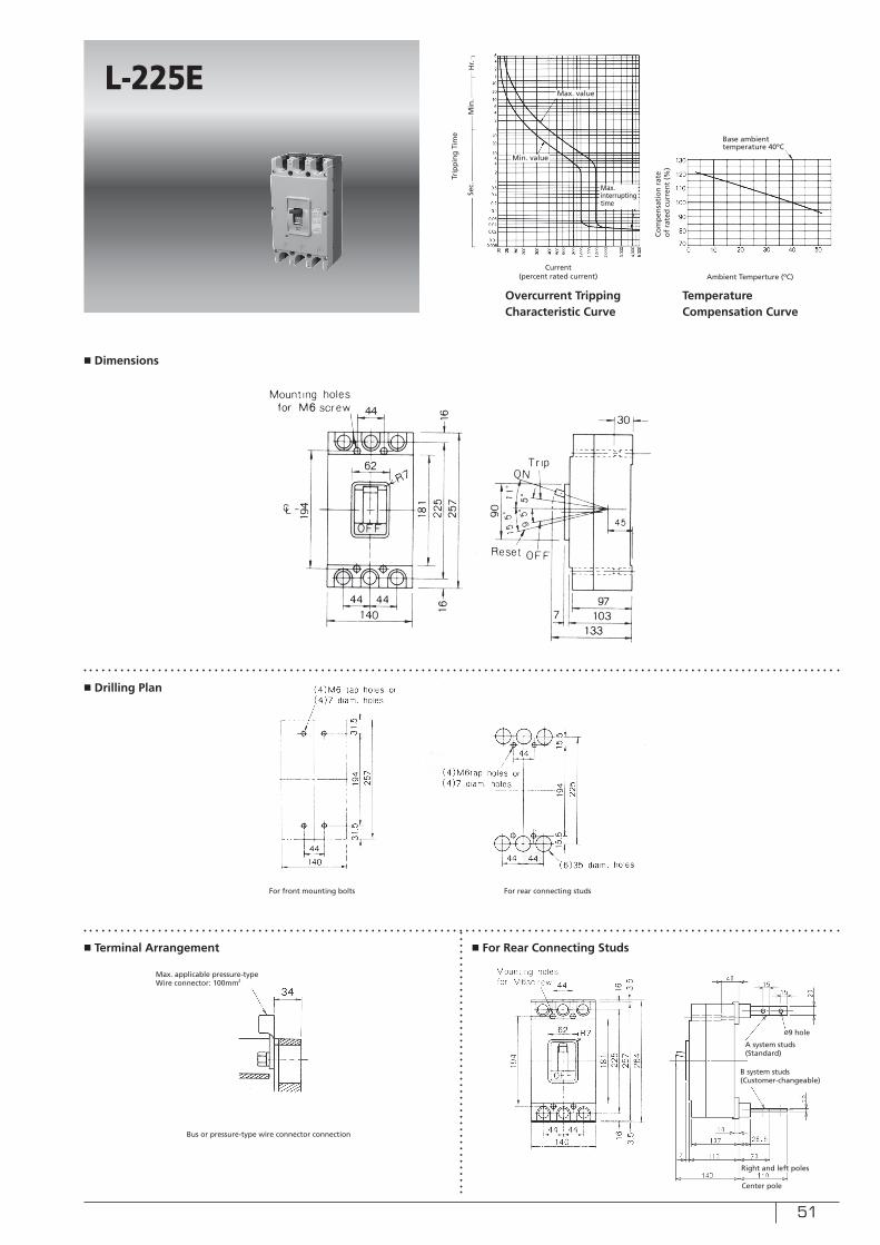
51
■ Dimensions
■ Drilling Plan
■ Terminal Arrangement ■ For Rear Connecting Studs
Min. value
Sec.
Min
.H
r.
Ambient Temperture (ºC)
Trip
pin
g T
ime
Max. value
Base ambient temperature 40ºC
L-225E
For front mounting bolts For rear connecting studs
Max. interrupting time
Current (percent rated current)
Overcurrent Tripping Characteristic Curve
Temperature Compensation Curve
Bus or pressure-type wire connector connection
A system studs(Standard)
B system studs(Customer-changeable)
Max. applicable pressure-typeWire connector: 100mm2
Co
mp
ensa
tio
n r
ate
of
rate
d c
urr
ent
(%)
Center pole
Right and left poles
ø9 hole
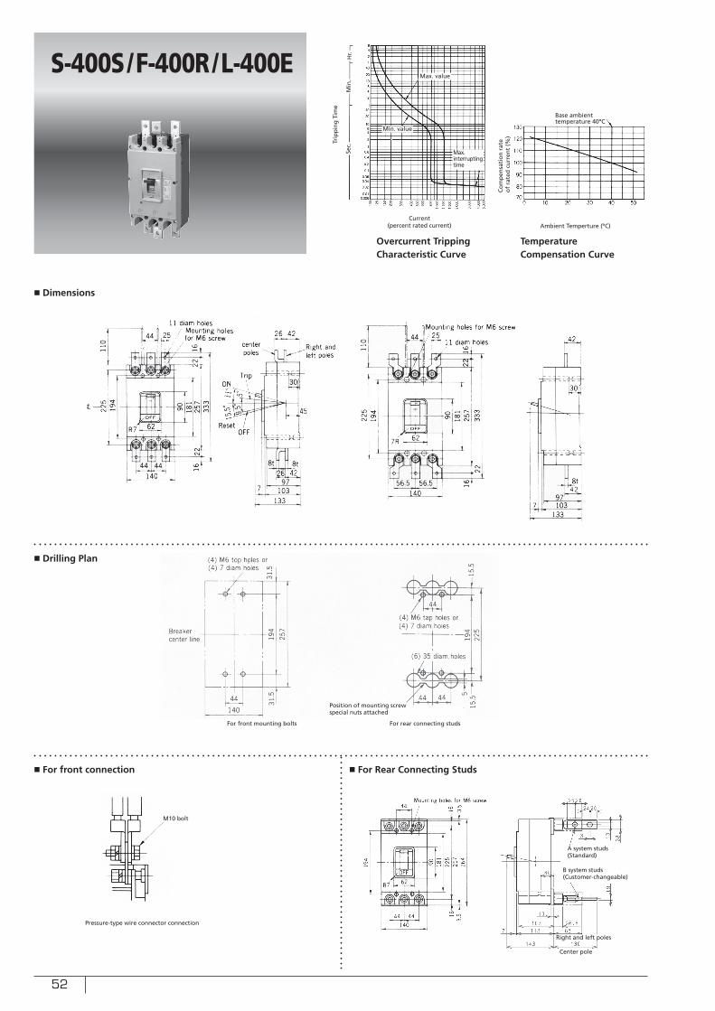
52
■ Dimensions
■ Drilling Plan
■ For front connection ■ For Rear Connecting Studs
Min. value
Sec.
Min
.H
r.
Ambient Temperture (ºC)
Trip
pin
g T
ime
Max. value
Base ambient temperature 40ºC
S-400S/F-400R/L-400E
Max. interrupting time
Current (percent rated current)
Overcurrent Tripping Characteristic Curve
Temperature Compensation Curve
Pressure-type wire connector connection
Position of mounting screw special nuts attached
For front mounting bolts For rear connecting studs
M10 bolt
Co
mp
ensa
tio
n r
ate
of
rate
d c
urr
ent
(%)
A system studs(Standard)
B system studs(Customer-changeable)
Center pole
Right and left poles
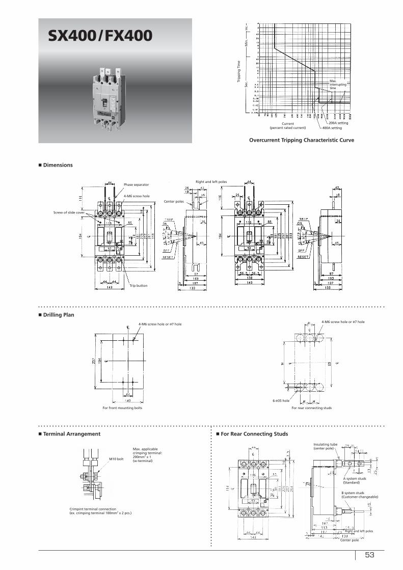
53
■ Dimensions
■ Drilling Plan
■ Terminal Arrangement ■ For Rear Connecting Studs
Sec.
Min
.H
r.
Trip
pin
g T
ime
SX400/FX400
Max. interrupting time
Current (percent rated current)
Overcurrent Tripping Characteristic Curve
Crimpint terminal connection(ex. crimping terminal 100mm2 x 2 pcs.)
For rear connecting studs
M10 bolt
200A setting400A setting
For front mounting bolts
4-M6 screw hole or ø7 hole4-M6 screw hole or ø7 hole
6-ø35 hole
Phase separator
4-M6 screw hole
Screw of slide cover
Center poles
Right and left poles
Max. applicable crimping terminal: 200mm2 x 1(w-terminal)
Trip button
Insulating tube (center pole)
A system studs(Standard)
B system studs(Customer-changeable)
Center pole
Right and left poles
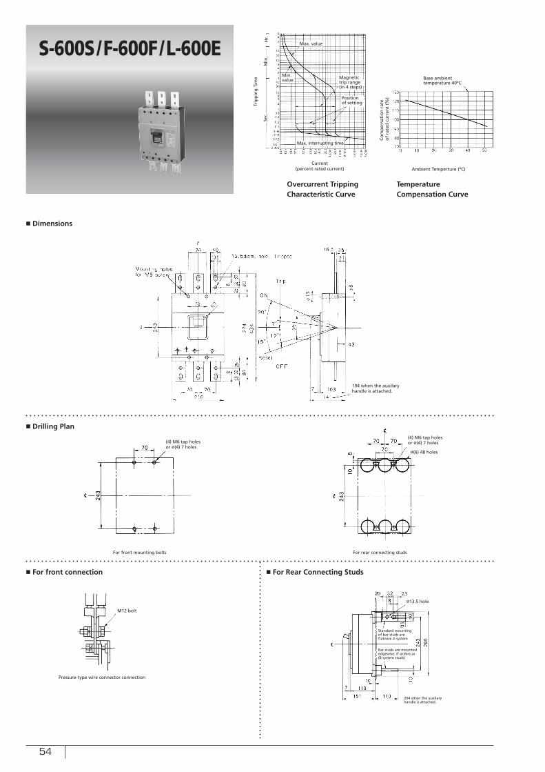
54
■ Dimensions
■ Drilling Plan
■ For front connection ■ For Rear Connecting Studs
Min. value
Sec.
Min
.H
r.
Ambient Temperture (ºC)
Trip
pin
g T
ime
Max. value
Base ambient temperature 40ºC
S-600S/F-600F/L-600E
Max. interrupting time
Current (percent rated current)
Overcurrent Tripping Characteristic Curve
Temperature Compensation Curve
Pressure-type wire connector connection
For front mounting bolts For rear connecting studs
M12 bolt
Magnetic trip range (in 4 steps)
Position of setting
(4) M6 tap holes or ø(4) 7 holes
(4) M6 tap holes or ø(4) 7 holes
ø(6) 48 holes
ø13.5 hole
Standard mounting of bar studs are flatwise A system
Bar studs are mounted edgewise, If orders as (B system studs)
204 when the auxilary handle is attached.
194 when the auxilary handle is attached.
Co
mp
ensa
tio
n r
ate
of
rate
d c
urr
ent
(%)

55
■ Dimensions
■ Drilling Plan
■ Terminal Arrangement ■ For Rear Connecting Studs
Sec.
Min
.H
r.
Trip
pin
g T
ime
SX600/FX600
Max. interrupting time
Current (percent rated current)
Overcurrent Tripping Characteristic Curve
Crimpint terminal connection(ex. crimping terminal 200mm2 x 2)
For rear connecting studs
M12 bolt
300A setting600A setting
For front mounting bolts
4-M6 screw hole or ø7 hole4-M6 screw hole or ø7 hole
ø48 hole
Phase separator4-M6 screw hole
Center poles
Trip button
Max. applicable crimping terminal: 200mm2 x 2
ø13.5 hole4-M6 screw hole
A system studs(Standard)
B system studs
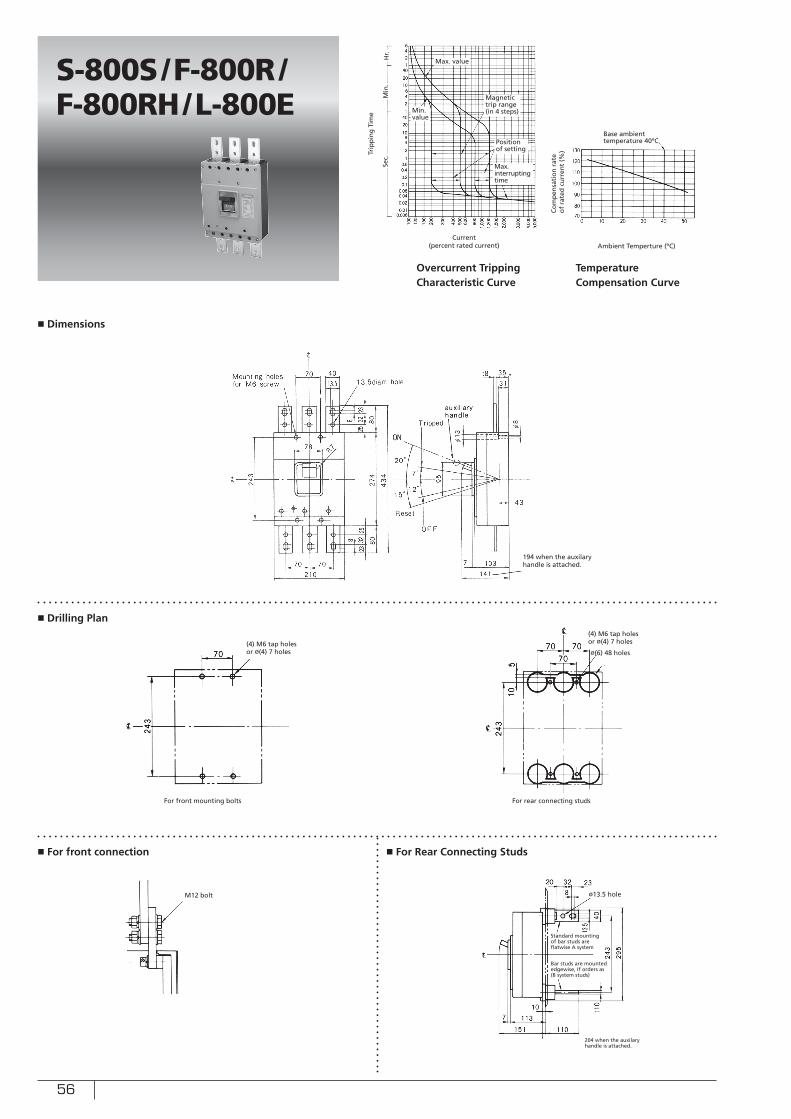
56
■ Dimensions
■ Drilling Plan
■ For front connection ■ For Rear Connecting Studs
Min. value
Sec.
Min
.H
r.
Ambient Temperture (ºC)
Trip
pin
g T
ime
Max. value
Base ambient temperature 40ºC
S-800S/F-800R/F-800RH/L-800E
Max. interrupting time
Current (percent rated current)
Overcurrent Tripping Characteristic Curve
Temperature Compensation Curve
For front mounting bolts For rear connecting studs
M12 bolt
Magnetic trip range (in 4 steps)
Position of setting
(4) M6 tap holes or ø(4) 7 holes
(4) M6 tap holes or ø(4) 7 holes
ø(6) 48 holes
ø13.5 hole
194 when the auxilary handle is attached.
Standard mounting of bar studs are flatwise A system
Bar studs are mounted edgewise, If orders as (B system studs)
204 when the auxilary handle is attached.
Co
mp
ensa
tio
n r
ate
of
rate
d c
urr
ent
(%)
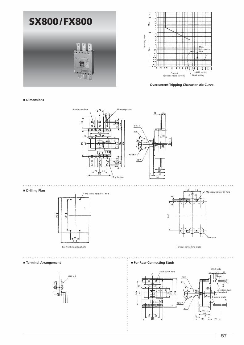
57
■ Dimensions
■ Drilling Plan
■ Terminal Arrangement ■ For Rear Connecting Studs
Sec.
Min
.H
r.
Trip
pin
g T
ime
SX800/FX800
Max. interrupting time
Current (percent rated current)
Overcurrent Tripping Characteristic Curve
For rear connecting studs
M12 bolt
400A setting800A setting
For front mounting bolts
4-M6 screw hole or ø7 hole4-M6 screw hole or ø7 hole
ø48 hole
Phase separator4-M6 screw hole
Trip button
ø13.5 hole4-M6 screw hole
A system studs(Standard)
B system studs
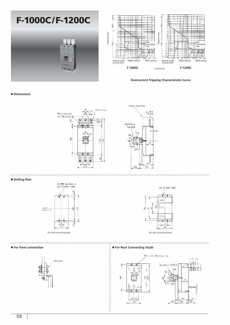
58
■ Dimensions
■ Drilling Plan
■ For front connection ■ For Rear Connecting Studs
Current (A)
Trip
pin
g T
ime
Trip
pin
g T
ime
Overcurrent Tripping Characteristic Curve
F-1000C/F-1200C
F-1000C F-1200C
For front mounting bolts For rear connecting studs
M12 bolt
Sec.
Sec.
Min
.
Min
.
Hr. Hr.
Max. interrupting time
Max. interrupting time
1000A setting 1200A setting500A setting 600A settingSetting range at short limit
Setting range at short limit
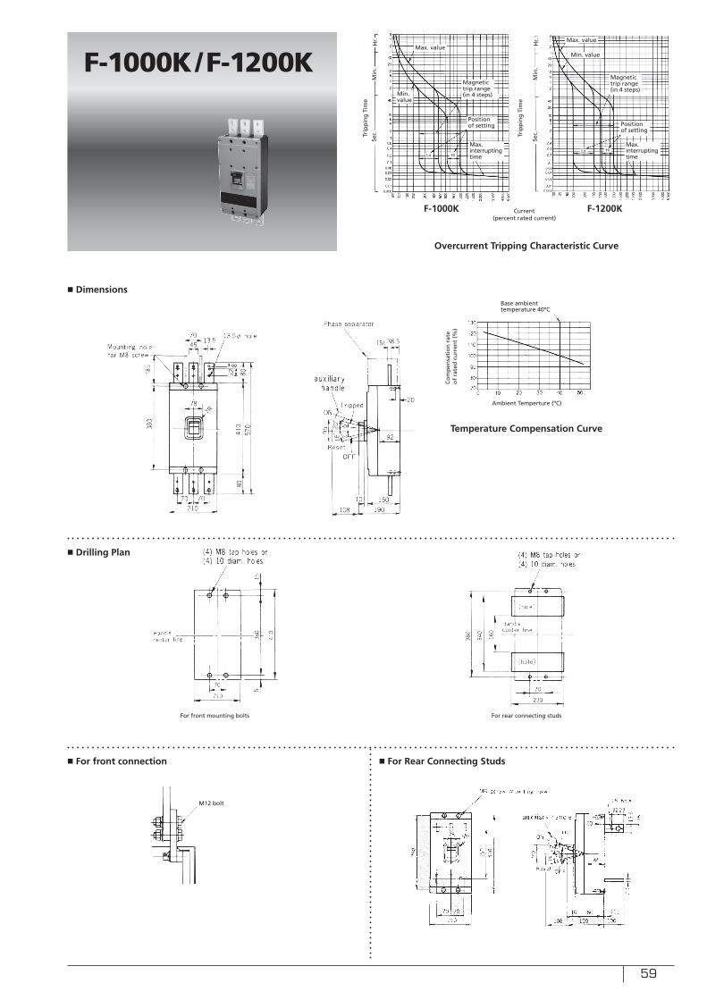
59
■ For front connection
M12 bolt
■ Dimensions
■ Drilling Plan
■ For Rear Connecting Studs
Ambient Temperture (ºC)
Current (percent rated current)
Trip
pin
g T
ime
Trip
pin
g T
ime
Overcurrent Tripping Characteristic Curve
Temperature Compensation Curve
Base ambient temperature 40ºC
F-1000K/F-1200K
F-1000K F-1200K
For front mounting bolts For rear connecting studs
Min. value
Min. value
Sec.
Sec.
Min
.
Min
.
Hr.
Hr.
Max. valueMax. value
Max. interrupting time
Max. interrupting time
Magnetic trip range (in 4 steps)
Magnetic trip range (in 4 steps)
Position of setting Position
of setting
Lo HiLo Hi
Co
mp
ensa
tio
n r
ate
of
rate
d c
urr
ent
(%)
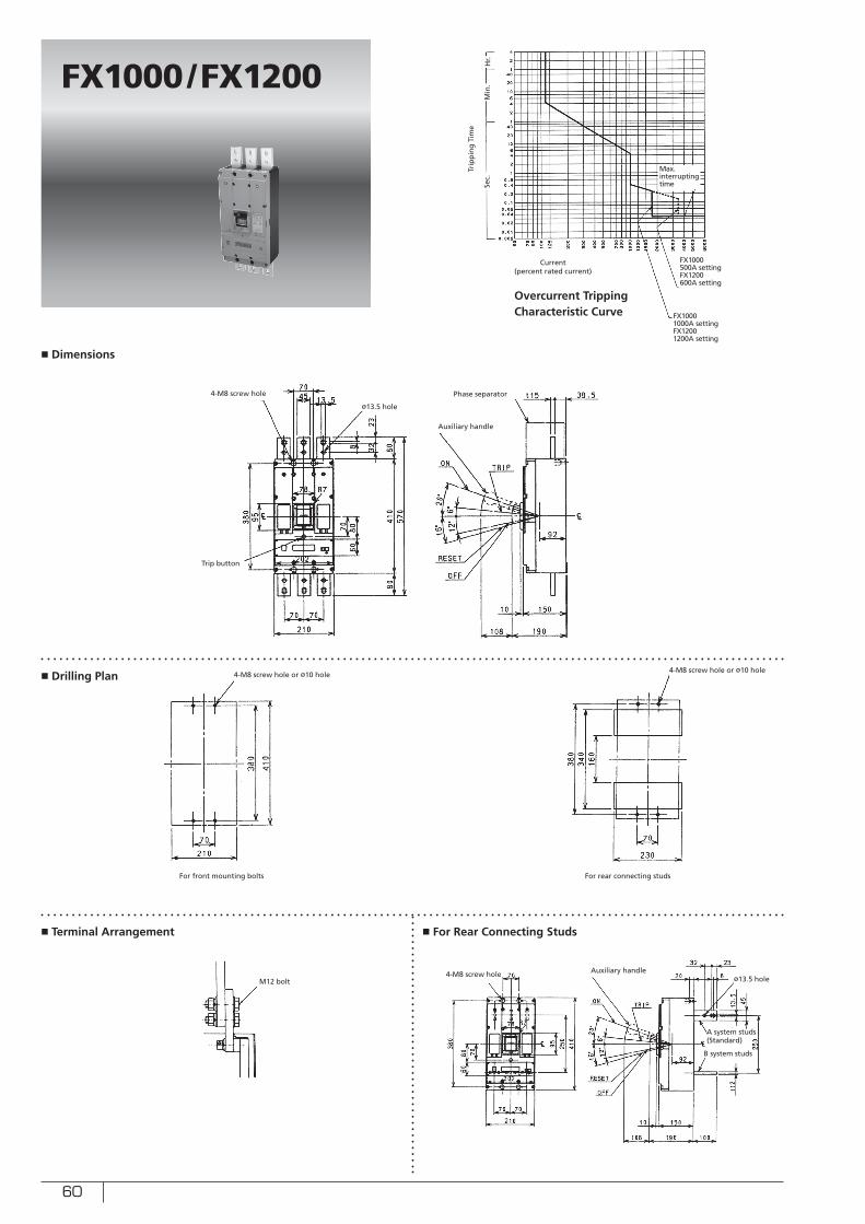
60
■ Dimensions
■ Drilling Plan
■ Terminal Arrangement ■ For Rear Connecting Studs
Sec.
Min
.H
r.
Trip
pin
g T
ime
FX1000/FX1200
Max. interrupting time
Current (percent rated current)
Overcurrent Tripping Characteristic Curve
For rear connecting studs
M12 bolt
FX1000500A settingFX1200600A setting
For front mounting bolts
4-M8 screw hole or ø10 hole
Phase separator4-M8 screw hole
Trip button
ø13.5 hole4-M8 screw hole
FX10001000A settingFX12001200A setting
ø13.5 hole
Auxiliary handle
4-M8 screw hole or ø10 hole
Auxiliary handle
A system studs(Standard)
B system studs
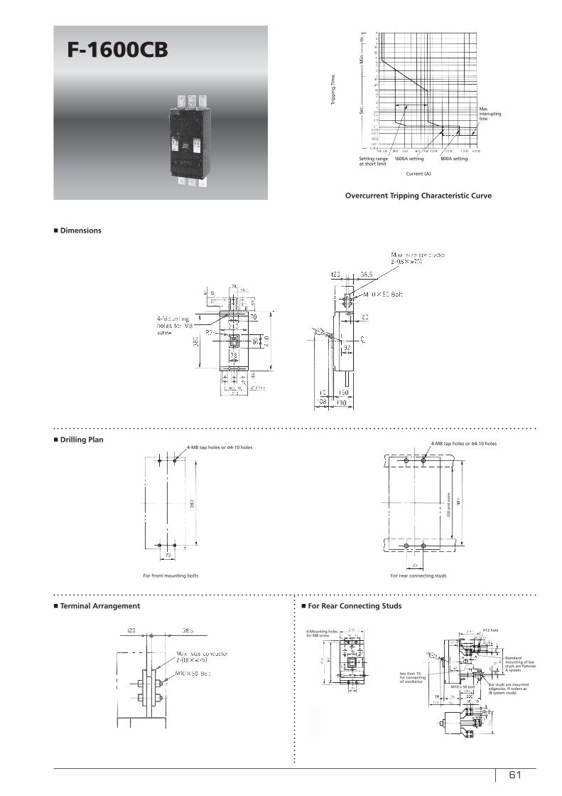
61
■ Dimensions
■ Drilling Plan
■ Terminal Arrangement ■ For Rear Connecting Studs
F-1600CB
For front mounting bolts For rear connecting studs
Trip
pin
g T
ime
Current (A)
Overcurrent Tripping Characteristic Curve
4-M8 tap holes or ø4-10 holes4-M8 tap holes or ø4-10 holes
4-Mounting holes for M8 screw
ø12 hole
320
and
mo
re
M10 x 50 bolt
Standard mounting of bar studs are flatwise A system
Bar studs are mounted edgewise, If orders as (B system studs)
less than 15 for connecting of conductor
Sec.
Min
.H
r.
Max. interrupting time
1600A setting 800A settingSetting range at short limit
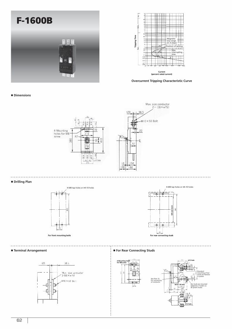
62
■ Dimensions
■ Drilling Plan
■ Terminal Arrangement ■ For Rear Connecting Studs
F-1600BF-1600B
For front mounting boltsFor front mounting bolts For rear connecting studsFor rear connecting studs
Trip
pin
g T
ime
Trip
pin
g T
ime
Overcurrent Tripping Characteristic Curve
4-M8 tap holes or ø4-10 holes 4-M8 tap holes or ø4-10 holes
4-Mounting holes for M8 screw4-Mounting holes for M8 screw
ø12 holeø12 hole
320
and
mo
re32
0 an
d m
ore
M10 x 50 boltM10 x 50 bolt
Standard mounting of bar studs are flatwise A system
Standard mounting of bar studs are flatwise A system
Bar studs are mounted edgewise, If orders as (B system studs)
Bar studs are mounted edgewise, If orders as (B system studs)
less than 15 for connecting of conductor
less than 15 for connecting of conductor
Current (percent rated current)
Current (percent rated current)
Sec.
Sec.
Min
.M
in.
Hr.
Hr.
Max. interrupting time
Max. interrupting time
Magnetic trip range (in 4 steps)
Magnetic trip range (in 4 steps)
Position of settingPosition of setting
LoLo HiHi
ø12 holeø12 hole
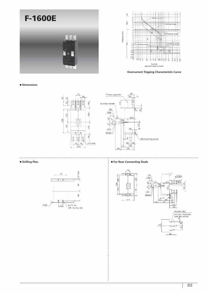
63
■ Dimensions
■ Drilling Plan ■ For Rear Connecting Studs
F-1600E
Trip
pin
g T
ime
Overcurrent Tripping Characteristic Curve
Current (percent rated current)
Sec.
Min
.H
r.
Rated current
[T1] Setting range
[I2] Setting range
[T2] Setting range [I3] Setting range
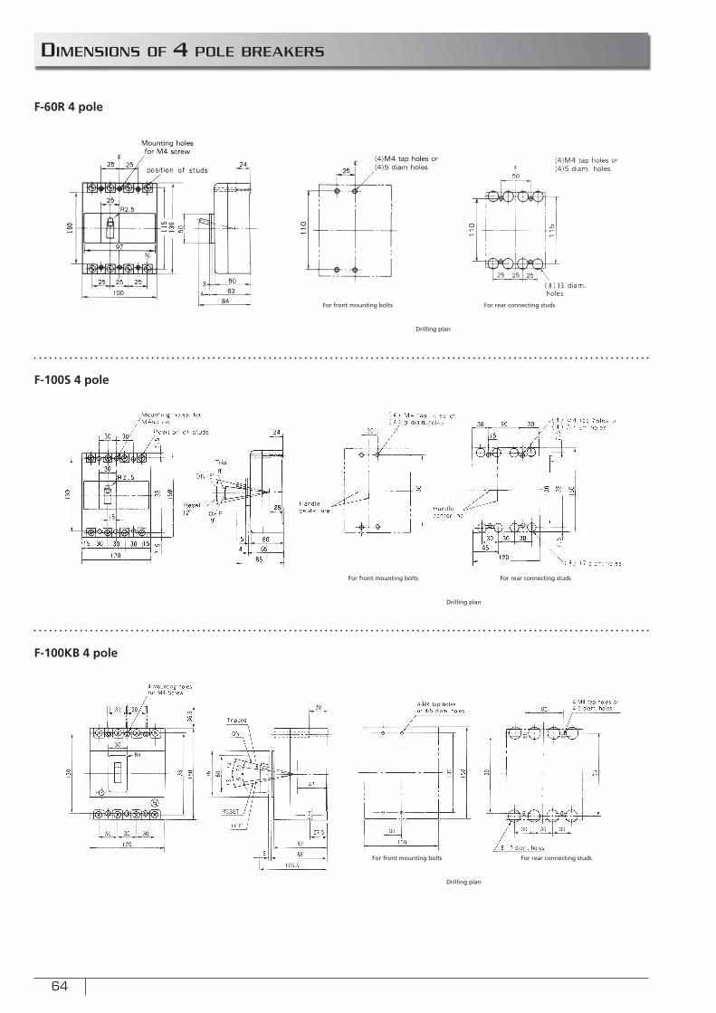
64
DIMENSIONS OF 4 POLE BREAKERS
F-60R 4 pole
F-100S 4 pole
F-100KB 4 pole
For front mounting bolts
For front mounting bolts
For front mounting bolts
For rear connecting studs
For rear connecting studs
For rear connecting studs
Drilling plan
Drilling plan
Drilling plan
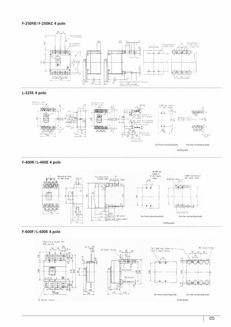
65
F-250FB/F-250KC 4 pole
L-225E 4 pole
F-400R/L-400E 4 pole
F-600F/L-600E 4 pole
For front mounting bolts
For front mounting bolts
For rear connecting studs
For rear connecting studs
Drilling plan
Drilling plan
For front mounting bolts For rear connecting studs
Drilling plan
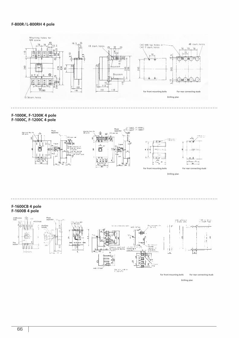
66
F-800R/L-800RH 4 pole
F-1000K, F-1200K 4 poleF-1000C, F-1200C 4 pole
F-1600CB 4 poleF-1600B 4 pole
For front mounting bolts
For front mounting bolts
For front mounting bolts
For rear connecting studs
For rear connecting studs
For rear connecting studs
Drilling plan
Drilling plan
Drilling plan
Phase separator
4-M8 screw hole
Trip button
ø13.5 hole
Auxiliary handle

67
■ Principle of operation
This device is composed of a zero phase current transformer for
detecting leakage current, a control circuit, and a Fuse-Free Breaker with a shunt trip.
As shown in Fig. 37, magnetic fl uxes cancel out each other, inducing no output voltage in the secondary coil while no leakage is present in the load circuit.
i1 + i2 + i3 = 0
If leakage current (lg) occurs in the load circuit, magnetic fl ux øg is induced, producing a certain voltage across the secondary coil.
i1 + i2 + i3 = ig
The induced voltage is supplied to the shunt trip coil of the Fuse-Free Breaker, through a control circuit composed of diodes and semiconductor control elements, to break the circuit.
Fig. 37 Principle of operation
cLassification and coMposition
ESeries RSeriesEarth Leakage Relay Series
30A – 800A frame 100A – 1200A frame –
Standard Breaker High Interrupting Breaker
EARTH LEAKAGE BREAKERS AND EARTH LEAKAGE RELAYS
This is a combination of a Fuse-Free Breaker and a leakage current detector for
preventing fi re or electric shock due to deterioration of electric insulation.
It will provide perfect protection of a circuit against overload,
short-circuit, or earth leakage.
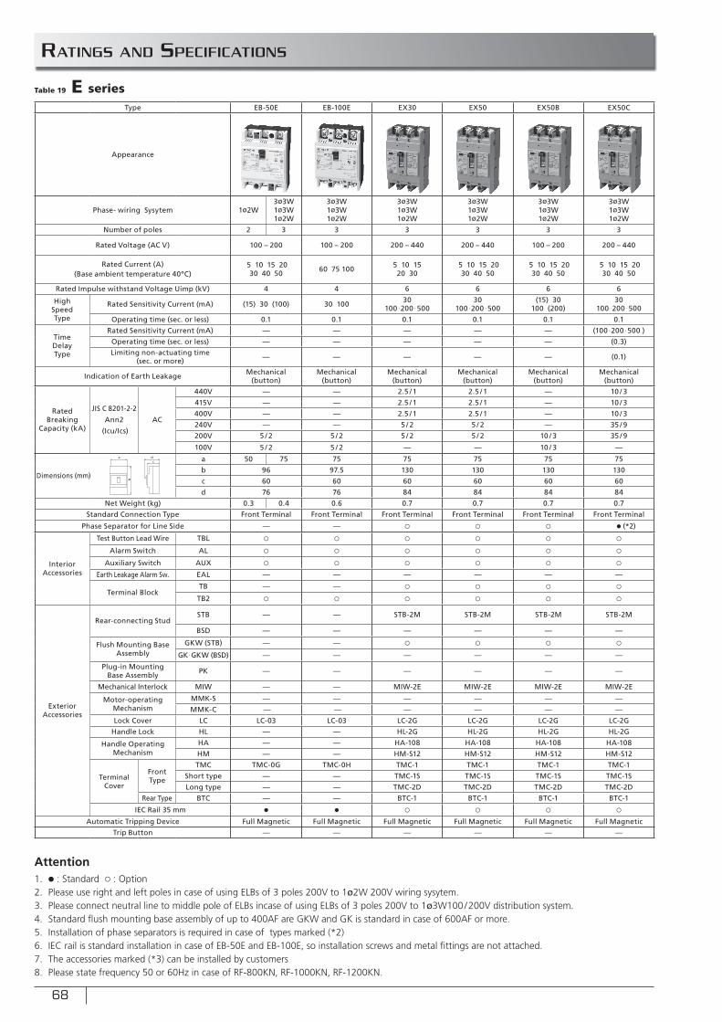
68
Ratings and specifications
Type EB-50E EB-100E EX30 EX50 EX50B EX50C EX100 EX100B EX225 EXK225 EX400 EX400B EX600B EX800B
Appearance
Phase- wiring Sysytem 1ø2W3ø3W1ø3W1ø2W
3ø3W1ø3W1ø2W
3ø3W1ø3W1ø2W
3ø3W1ø3W1ø2W
3ø3W1ø3W1ø2W
3ø3W1ø3W1ø2W
3ø3W1ø3W1ø2W
3ø3W1ø3W1ø2W
3ø3W1ø3W1ø2W
3ø3W1ø3W1ø2W
3ø3W1ø3W1ø2W
3ø3W1ø3W1ø2W
3ø3W1ø3W1ø2W
3ø3W1ø3W1ø2W
Number of poles 2 3 3 3 3 3 3 3 3 3 3 3 3 3 3
Rated Voltage (AC V) 100 – 200 100 – 200 200 – 440 200 – 440 100 – 200 200 – 440 100 – 200 200 – 440 200 – 440(100 – 200)
200 – 440(100 – 200)
200 – 440(100 – 200) 200 – 440 200 – 440 200 – 440
Rated Current (A)(Base ambient temperature 40ºC)
5 10 15 20 30 40 50 60 75 100 5 10 15
20 30 5 10 15 20
30 40 50 5 10 15 20
30 40 50 5 10 15 20
30 40 50 50 60 75 100 50 60 75 100 125 150 175200 225
125 150 175200 225
250 300350 400
200 / 225 / 250300 / 350 /400
adjustable
300 / 350 /400500 / 600
adjustable
400 /450 / 500600 / 700 / 800
adjustable
Rated Impulse withstand Voltage Uimp (kV) 4 4 6 6 6 6 6 6 6 6 8 8 8 8
High Speed Type
Rated Sensitivity Current (mA) (15) 30 (100) 30 100 30100 ∙200 ∙500
30100 ∙200 ∙500
(15) 30100 (200)
30100 ∙200 ∙500
(15) 30100 (200)
30100 ∙200 ∙500
30100 ∙200 ∙500
30100 ∙200 ∙500
(30)100 ∙200 ∙500
(30)100 ∙200 ∙500 100 ∙200 ∙500 100 ∙200 ∙500
Operating time (sec. or less) 0.1 0.1 0.1 0.1 0.1 0.1 0.1 0.1 0.1 0.1 0.1 0.1 0.1 0.1
Time Delay Type
Rated Sensitivity Current (mA) — — — — — (100 ∙200 ∙500 ) — (100 ∙200 ∙500 ) (100 ∙200 ∙500 ) (100 ∙200 ∙500 ) (100 ∙200 ∙500 ) (100 ∙200 ∙500 ) (100 ∙200 ∙500 ) (100 ∙200 ∙500 )
Operating time (sec. or less) — — — — — (0.3) — (0.3) (0.3 0.6 1.2) (0.3 0.6 1.2) (0.3 0.6 1.2) (0.3 0.6 1.2) (0.3 0.6 1.2) (0.3 0.6 1.2)
Limiting non-actuating time (sec. or more) — — — — — (0.1) — (0.1) (0.1 0.2 0.5) (0.1 0.2 0.5) (0.1 0.2 0.5) (0.1 0.2 0.5) (0.1 0.2 0.5) (0.1 0.2 0.5)
Indication of Earth Leakage Mechanical(button)
Mechanical(button)
Mechanical(button)
Mechanical(button)
Mechanical(button)
Mechanical(button)
Mechanical(button)
Mechanical(button)
Mechanical(button)
Mechanical(button)
Mechanical(button)
Mechanical(button)
Mechanical(button)
Mechanical(button)
Rated Breaking
Capacity (kA)
JIS C 8201-2-2
Ann2
(Icu/Ics)
AC
440V — — 2.5 / 1 2.5 / 1 — 10 / 3 — 10 / 3 15 / 8 15 / 8 36 / 18 36 / 18 36 / 18 36 / 18
415V — — 2.5 / 1 2.5 / 1 — 10 / 3 — 10 / 3 15 / 8 15 / 8 36 / 18 36 / 18 36 / 18 36 / 18
400V — — 2.5 / 1 2.5 / 1 — 10 / 3 — 10 / 3 15 / 8 15 / 8 36 / 18 36 / 18 36 / 18 36 / 18
240V — — 5 / 2 5 / 2 — 35 / 9 — 35 / 9 35 / 18 35 / 18 50 / 25 50 / 25 50 / 25 50 / 25
200V 5 / 2 5 / 2 5 / 2 5 / 2 10 / 3 35 / 9 10 / 3 35 / 9 35 / 18 35 / 18 50 / 25 50 / 25 50 / 25 50 / 25
100V 5 / 2 5 / 2 — — 10 / 3 — 10 / 3 — — — — — — —
Dimensions (mm)
a 50 75 75 75 75 75 75 75 75 105 105 140 140 210 210
b 96 97.5 130 130 130 130 130 130 165 165 257 257 274 274
c 60 60 60 60 60 60 60 60 60 68 103 103 103 103
d 76 76 84 84 84 84 84 84 85 93 133 133 141 141
Net Weight (kg) 0.3 0.4 0.6 0.7 0.7 0.7 0.7 0.8 0.9 2.2 2.2 6.6 6.5 10.6 12.9
Standard Connection Type Front Terminal Front Terminal Front Terminal Front Terminal Front Terminal Front Terminal Front Terminal Front Terminal Front Terminal Front Terminal Front Bar Terminal Front Bar Terminal Front Bar Terminal Front Bar Terminal
Phase Separator for Line Side — — ○ ○ ○ ● (*2) ○ ● (*2) ● (*2) ● (*2) ● (*2) ● (*2) ● (*2) ● (*2)
Interior Accessories
Test Button Lead Wire TBL ○ ○ ○ ○ ○ ○ ○ ○ ○ ○ ○ ○ ○ ○
Alarm Switch AL ○ ○ ○ ○ ○ ○ ○ ○ ○ ○ (*3) ○ ○ (*3) ○ (*3) ○ (*3)
Auxiliary Switch AUX ○ ○ ○ ○ ○ ○ ○ ○ ○ ○ (*3) ○ ○ (*3) ○ (*3) ○ (*3)
Earth Leakage Alarm Sw. EAL — — — — — — — — — — — — — —
Terminal BlockTB — — ○ ○ ○ ○ ○ ○ ○ ○ ○ ○ ○ ○
TB2 ○ ○ ○ ○ ○ ○ ○ ○ ○ ○ ○ ○ ○ ○
Exterior Accessories
Rear-connecting StudSTB — — STB-2M STB-2M STB-2M STB-2M STB-3K
(50A:STB-2M)STB-3K
(50A:STB-2M) — — — — — —
BSD — — — — — — — — ○ ○ ○ ○ ○ ○
Flush Mounting Base Assembly
GKW (STB) — — ○ ○ ○ ○ ○ ○ — — — — — —
GK∙GKW (BSD) — — — — — — — — ○ ○ ○ ○ ○ (GK) ○ (GK)
Plug-in Mounting Base Assembly PK — — — — — — — — — — — — — —
Mechanical Interlock MIW — — MIW-2E MIW-2E MIW-2E MIW-2E MIW-2E MIW-2E MIW-4F MIW-4L ○ MIW-5F MIW-5G MIW-5G
Motor-operating Mechanism
MMK-S — — — — — — — — — — — — — —
MMK-C — — — — — — — — — — — — — —
Lock Cover LC LC-03 LC-03 LC-2G LC-2G LC-2G LC-2G LC-2G LC-2G LC-4E LC-2F — — — —
Handle Lock HL — — HL-2G HL-2G HL-2G HL-2G HL-2G HL-2G HL-4E HL-2F HL-5 HL-5 HL-6 HL-6
Handle Operating Mechanism
HA — — HA-108 HA-108 HA-108 HA-108 HA-108 HA-108 HA-207 HA-209 HA-405 HA-406 HA-402 HA-402
HM — — HM-S12 HM-S12 HM-S12 HM-S12 HM-S12 HM-S12 HM-S22 HM-S23 — — — —
Terminal Cover
Front Type
TMC TMC-0G TMC-0H TMC-1 TMC-1 TMC-1 TMC-1 TMC-1 TMC-1 TMC-4K TMC-4J TMC-5B TMC-5B TMC-5D TMC-5D
Short type — — TMC-1S TMC-1S TMC-1S TMC-1S TMC-1S TMC-1S TMC-4JS TMC-4JS — — — —
Long type — — TMC-2D TMC-2D TMC-2D TMC-2D TMC-2D TMC-2D — — — — — —
Rear Type BTC — — BTC-1 BTC-1 BTC-1 BTC-1 BTC-1 BTC-1 BTC-4G BTC-4J BTC-5B BTC-5B — —
IEC Rail 35 mm ● ● ○ ○ ○ ○ ○ ○ — — — — — —
Automatic Tripping Device Full Magnetic Full Magnetic Full Magnetic Full Magnetic Full Magnetic Full Magnetic Full Magnetic Full Magnetic Thermal-Magnetic Thermal-Magnetic Thermal-Magnetic Electric Relay Electric Relay Electric Relay
Trip Button — — — — — — — — — ● — ● ● ●
a
b
dc
Table 19 E series
Attention1. ● : Standard ○ : Option2. Please use right and left poles in case of using ELBs of 3 poles 200V to 1ø2W 200V wiring sysytem.3. Please connect neutral line to middle pole of ELBs incase of using ELBs of 3 poles 200V to 1ø3W100/200V distribution system.4. Standard fl ush mounting base assembly of up to 400AF are GKW and GK is standard in case of 600AF or more.5. Installation of phase separators is required in case of types marked (*2)6. IEC rail is standard installation in case of EB-50E and EB-100E, so installation screws and metal fi ttings are not attached.7. The accessories marked (*3) can be installed by customers8. Please state frequency 50 or 60Hz in case of RF-800KN, RF-1000KN, RF-1200KN.
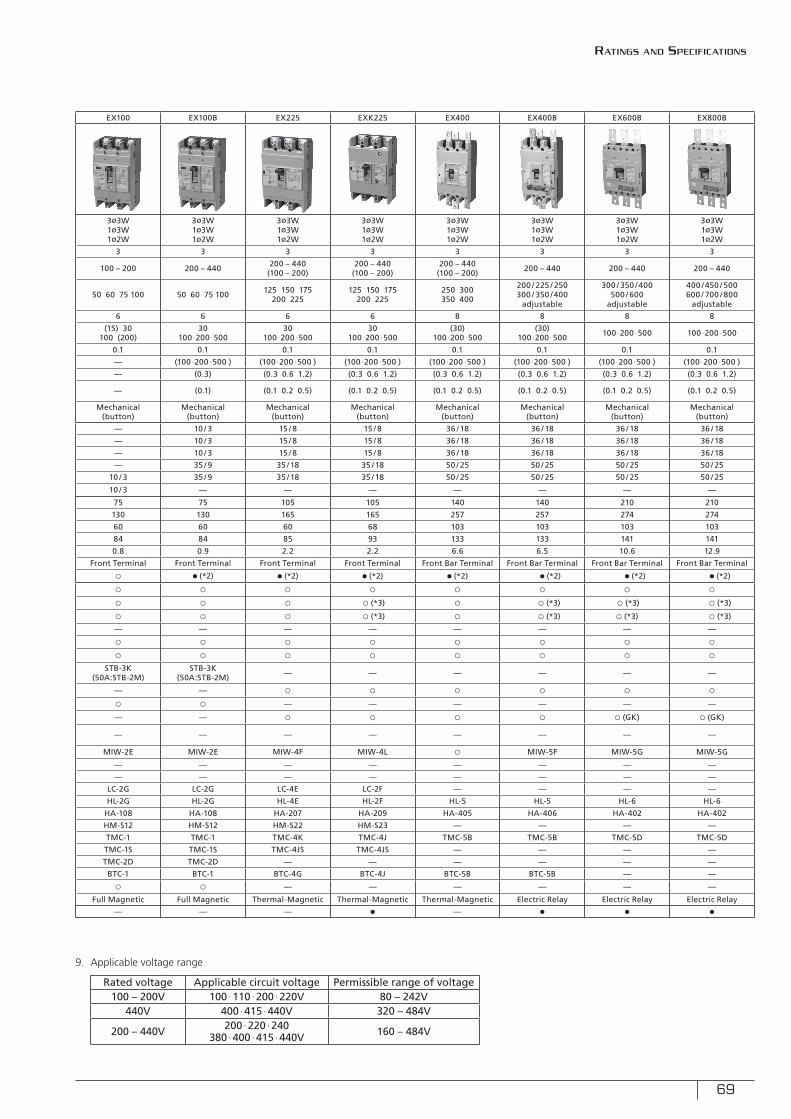
69
Type EB-50E EB-100E EX30 EX50 EX50B EX50C EX100 EX100B EX225 EXK225 EX400 EX400B EX600B EX800B
Appearance
Phase- wiring Sysytem 1ø2W3ø3W1ø3W1ø2W
3ø3W1ø3W1ø2W
3ø3W1ø3W1ø2W
3ø3W1ø3W1ø2W
3ø3W1ø3W1ø2W
3ø3W1ø3W1ø2W
3ø3W1ø3W1ø2W
3ø3W1ø3W1ø2W
3ø3W1ø3W1ø2W
3ø3W1ø3W1ø2W
3ø3W1ø3W1ø2W
3ø3W1ø3W1ø2W
3ø3W1ø3W1ø2W
3ø3W1ø3W1ø2W
Number of poles 2 3 3 3 3 3 3 3 3 3 3 3 3 3 3
Rated Voltage (AC V) 100 – 200 100 – 200 200 – 440 200 – 440 100 – 200 200 – 440 100 – 200 200 – 440 200 – 440(100 – 200)
200 – 440(100 – 200)
200 – 440(100 – 200) 200 – 440 200 – 440 200 – 440
Rated Current (A)(Base ambient temperature 40ºC)
5 10 15 20 30 40 50 60 75 100 5 10 15
20 30 5 10 15 20
30 40 50 5 10 15 20
30 40 50 5 10 15 20
30 40 50 50 60 75 100 50 60 75 100 125 150 175200 225
125 150 175200 225
250 300350 400
200 / 225 / 250300 / 350 /400
adjustable
300 / 350 /400500 / 600
adjustable
400 /450 / 500600 / 700 / 800
adjustable
Rated Impulse withstand Voltage Uimp (kV) 4 4 6 6 6 6 6 6 6 6 8 8 8 8
High Speed Type
Rated Sensitivity Current (mA) (15) 30 (100) 30 100 30100 ∙200 ∙500
30100 ∙200 ∙500
(15) 30100 (200)
30100 ∙200 ∙500
(15) 30100 (200)
30100 ∙200 ∙500
30100 ∙200 ∙500
30100 ∙200 ∙500
(30)100 ∙200 ∙500
(30)100 ∙200 ∙500 100 ∙200 ∙500 100 ∙200 ∙500
Operating time (sec. or less) 0.1 0.1 0.1 0.1 0.1 0.1 0.1 0.1 0.1 0.1 0.1 0.1 0.1 0.1
Time Delay Type
Rated Sensitivity Current (mA) — — — — — (100 ∙200 ∙500 ) — (100 ∙200 ∙500 ) (100 ∙200 ∙500 ) (100 ∙200 ∙500 ) (100 ∙200 ∙500 ) (100 ∙200 ∙500 ) (100 ∙200 ∙500 ) (100 ∙200 ∙500 )
Operating time (sec. or less) — — — — — (0.3) — (0.3) (0.3 0.6 1.2) (0.3 0.6 1.2) (0.3 0.6 1.2) (0.3 0.6 1.2) (0.3 0.6 1.2) (0.3 0.6 1.2)
Limiting non-actuating time (sec. or more) — — — — — (0.1) — (0.1) (0.1 0.2 0.5) (0.1 0.2 0.5) (0.1 0.2 0.5) (0.1 0.2 0.5) (0.1 0.2 0.5) (0.1 0.2 0.5)
Indication of Earth Leakage Mechanical(button)
Mechanical(button)
Mechanical(button)
Mechanical(button)
Mechanical(button)
Mechanical(button)
Mechanical(button)
Mechanical(button)
Mechanical(button)
Mechanical(button)
Mechanical(button)
Mechanical(button)
Mechanical(button)
Mechanical(button)
Rated Breaking
Capacity (kA)
JIS C 8201-2-2
Ann2
(Icu/Ics)
AC
440V — — 2.5 / 1 2.5 / 1 — 10 / 3 — 10 / 3 15 / 8 15 / 8 36 / 18 36 / 18 36 / 18 36 / 18
415V — — 2.5 / 1 2.5 / 1 — 10 / 3 — 10 / 3 15 / 8 15 / 8 36 / 18 36 / 18 36 / 18 36 / 18
400V — — 2.5 / 1 2.5 / 1 — 10 / 3 — 10 / 3 15 / 8 15 / 8 36 / 18 36 / 18 36 / 18 36 / 18
240V — — 5 / 2 5 / 2 — 35 / 9 — 35 / 9 35 / 18 35 / 18 50 / 25 50 / 25 50 / 25 50 / 25
200V 5 / 2 5 / 2 5 / 2 5 / 2 10 / 3 35 / 9 10 / 3 35 / 9 35 / 18 35 / 18 50 / 25 50 / 25 50 / 25 50 / 25
100V 5 / 2 5 / 2 — — 10 / 3 — 10 / 3 — — — — — — —
Dimensions (mm)
a 50 75 75 75 75 75 75 75 75 105 105 140 140 210 210
b 96 97.5 130 130 130 130 130 130 165 165 257 257 274 274
c 60 60 60 60 60 60 60 60 60 68 103 103 103 103
d 76 76 84 84 84 84 84 84 85 93 133 133 141 141
Net Weight (kg) 0.3 0.4 0.6 0.7 0.7 0.7 0.7 0.8 0.9 2.2 2.2 6.6 6.5 10.6 12.9
Standard Connection Type Front Terminal Front Terminal Front Terminal Front Terminal Front Terminal Front Terminal Front Terminal Front Terminal Front Terminal Front Terminal Front Bar Terminal Front Bar Terminal Front Bar Terminal Front Bar Terminal
Phase Separator for Line Side — — ○ ○ ○ ● (*2) ○ ● (*2) ● (*2) ● (*2) ● (*2) ● (*2) ● (*2) ● (*2)
Interior Accessories
Test Button Lead Wire TBL ○ ○ ○ ○ ○ ○ ○ ○ ○ ○ ○ ○ ○ ○
Alarm Switch AL ○ ○ ○ ○ ○ ○ ○ ○ ○ ○ (*3) ○ ○ (*3) ○ (*3) ○ (*3)
Auxiliary Switch AUX ○ ○ ○ ○ ○ ○ ○ ○ ○ ○ (*3) ○ ○ (*3) ○ (*3) ○ (*3)
Earth Leakage Alarm Sw. EAL — — — — — — — — — — — — — —
Terminal BlockTB — — ○ ○ ○ ○ ○ ○ ○ ○ ○ ○ ○ ○
TB2 ○ ○ ○ ○ ○ ○ ○ ○ ○ ○ ○ ○ ○ ○
Exterior Accessories
Rear-connecting StudSTB — — STB-2M STB-2M STB-2M STB-2M STB-3K
(50A:STB-2M)STB-3K
(50A:STB-2M) — — — — — —
BSD — — — — — — — — ○ ○ ○ ○ ○ ○
Flush Mounting Base Assembly
GKW (STB) — — ○ ○ ○ ○ ○ ○ — — — — — —
GK∙GKW (BSD) — — — — — — — — ○ ○ ○ ○ ○ (GK) ○ (GK)
Plug-in Mounting Base Assembly PK — — — — — — — — — — — — — —
Mechanical Interlock MIW — — MIW-2E MIW-2E MIW-2E MIW-2E MIW-2E MIW-2E MIW-4F MIW-4L ○ MIW-5F MIW-5G MIW-5G
Motor-operating Mechanism
MMK-S — — — — — — — — — — — — — —
MMK-C — — — — — — — — — — — — — —
Lock Cover LC LC-03 LC-03 LC-2G LC-2G LC-2G LC-2G LC-2G LC-2G LC-4E LC-2F — — — —
Handle Lock HL — — HL-2G HL-2G HL-2G HL-2G HL-2G HL-2G HL-4E HL-2F HL-5 HL-5 HL-6 HL-6
Handle Operating Mechanism
HA — — HA-108 HA-108 HA-108 HA-108 HA-108 HA-108 HA-207 HA-209 HA-405 HA-406 HA-402 HA-402
HM — — HM-S12 HM-S12 HM-S12 HM-S12 HM-S12 HM-S12 HM-S22 HM-S23 — — — —
Terminal Cover
Front Type
TMC TMC-0G TMC-0H TMC-1 TMC-1 TMC-1 TMC-1 TMC-1 TMC-1 TMC-4K TMC-4J TMC-5B TMC-5B TMC-5D TMC-5D
Short type — — TMC-1S TMC-1S TMC-1S TMC-1S TMC-1S TMC-1S TMC-4JS TMC-4JS — — — —
Long type — — TMC-2D TMC-2D TMC-2D TMC-2D TMC-2D TMC-2D — — — — — —
Rear Type BTC — — BTC-1 BTC-1 BTC-1 BTC-1 BTC-1 BTC-1 BTC-4G BTC-4J BTC-5B BTC-5B — —
IEC Rail 35 mm ● ● ○ ○ ○ ○ ○ ○ — — — — — —
Automatic Tripping Device Full Magnetic Full Magnetic Full Magnetic Full Magnetic Full Magnetic Full Magnetic Full Magnetic Full Magnetic Thermal-Magnetic Thermal-Magnetic Thermal-Magnetic Electric Relay Electric Relay Electric Relay
Trip Button — — — — — — — — — ● — ● ● ●
9. Applicable voltage range
Rated voltage Applicable circuit voltage Permissible range of voltage 100 – 200V 100 ∙110 ∙200 ∙220V 80 – 242V
440V 400 ∙415 ∙440V 320 – 484V
200 – 440V 200 ∙220 ∙240380 ∙400 ∙415 ∙440V 160 – 484V
Ratings and specifications
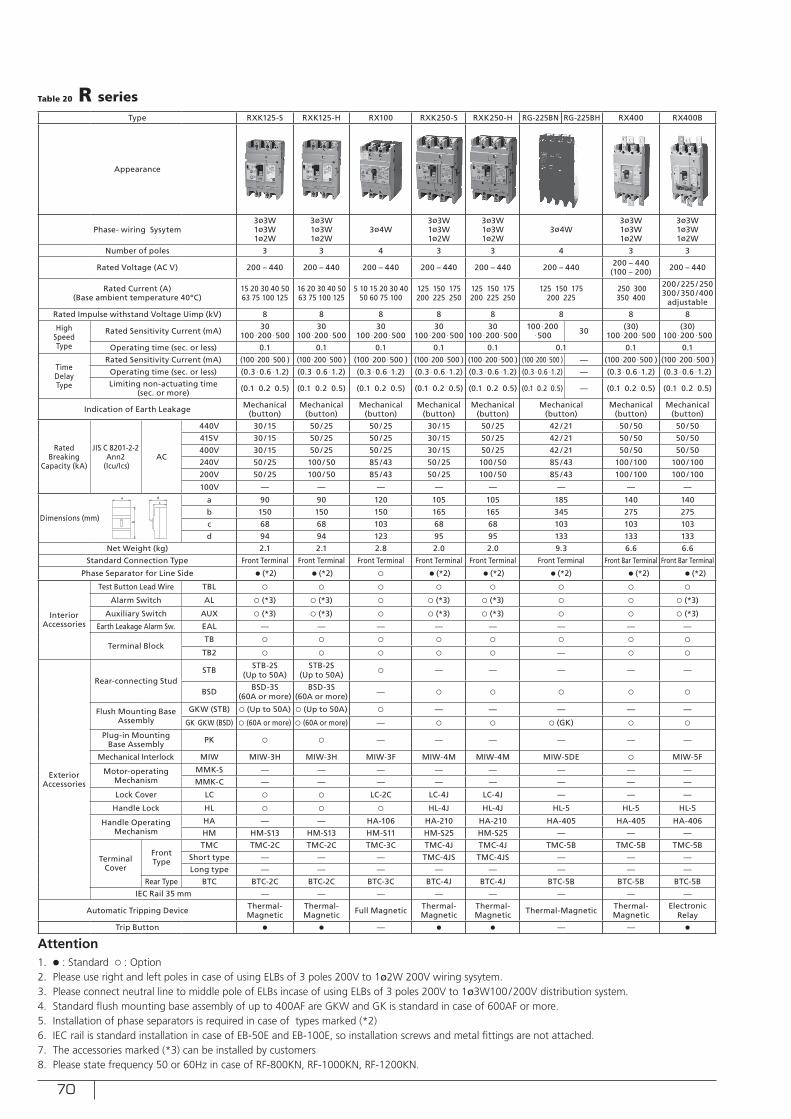
70
Type RXK125-S RXK125-H RX100 RXK250-S RXK250-H RG-225BN RG-225BH RX400 RX400B RG-400BN RG-400BH RX600B RF-600FN RX800B RF-800KN RF-1000KN RF-1000CBN RF-1200KN RF-1200CBN
Appearance
Phase- wiring Sysytem3ø3W1ø3W1ø2W
3ø3W1ø3W1ø2W
3ø4W3ø3W1ø3W1ø2W
3ø3W1ø3W1ø2W
3ø4W3ø3W1ø3W1ø2W
3ø3W1ø3W1ø2W
3ø4W3ø3W1ø3W1ø2W
3ø4W3ø3W1ø3W1ø2W
3ø4W3ø3W1ø3W1ø2W
3ø4W3ø3W1ø3W1ø2W
3ø3W1ø3W1ø2W
3ø4W3ø3W1ø3W1ø2W
Number of poles 3 3 4 3 3 4 3 3 4 3 4 3 4 3 4 3 3 4 3
Rated Voltage (AC V) 200 – 440 200 – 440 200 – 440 200 – 440 200 – 440 200 – 440 200 – 440(100 – 200) 200 – 440 200 – 440 200 – 440 440 (200) 200 – 440 440 (200) 440 (200) 440 (200) 440 (200) 440 (200)
Rated Current (A)(Base ambient temperature 40ºC)
15 20 30 40 50 63 75 100 125
16 20 30 40 50 63 75 100 125
5 10 15 20 30 40 50 60 75 100
125 150 175200 225 250
125 150 175200 225 250
125 150 175200 225
250 300350 400
200 / 225 / 250300 / 350 /400
adjustable
250 300350 400
300 / 350 /400500 / 600
adjustable500 600
400 /450 / 500600 / 700 / 800
adjustable700 800 1000
500 / 600 / 700800 / 900 / 1000
adjustable1200
600 / 700 / 8001000 / 1200adjustable
Rated Impulse withstand Voltage Uimp (kV) 8 8 8 8 8 8 8 8 8 8 8 8 8 8 8 8 8
High Speed Type
Rated Sensitivity Current (mA) 30100 ∙200 ∙500
30100 ∙200 ∙500
30100 ∙200 ∙500
30100 ∙200 ∙500
30100 ∙200 ∙500
100 ∙200∙500 30 (30)
100 ∙200 ∙500 (30)
100 ∙200 ∙500 100 ∙200 ∙500 30 100 ∙200 ∙500 50 ∙100 ∙200500 ∙1000 100 ∙200 ∙500 50 ∙100 ∙200
500 ∙100050 ∙100 ∙200500 ∙1000
50 ∙100 ∙200500 ∙1000
50 ∙100 ∙200500 ∙1000
50 ∙100 ∙200500 ∙1000
Operating time (sec. or less) 0.1 0.1 0.1 0.1 0.1 0.1 0.1 0.1 0.1 0.1 0.1 0.1 0.1 0.1 0.1 0.1 0.1
Time Delay Type
Rated Sensitivity Current (mA) (100 ∙200 ∙500 ) (100 ∙200 ∙500 ) (100 ∙200 ∙500 ) (100 ∙200 ∙500 ) (100 ∙200 ∙500 ) (100 ∙200 ∙500 ) — (100 ∙200 ∙500 ) (100 ∙200 ∙500 ) (100 ∙200 ∙500 ) — (100 ∙200 ∙500 ) (100 ∙200 ∙500 ) (100 ∙200 ∙500 ) (100 ∙200 ∙500 ) (100 ∙200 ∙500 ) (100 ∙200 ∙500 ) (100 ∙200 ∙500 ) (100 ∙200 ∙500 )
Operating time (sec. or less) (0.3 ∙ 0.6 ∙1.2) (0.3 ∙ 0.6 ∙1.2) (0.3 ∙ 0.6 ∙1.2) (0.3 ∙ 0.6 ∙1.2) (0.3 ∙ 0.6 ∙1.2) (0.3 ∙ 0.6 ∙1.2) — (0.3 ∙ 0.6 ∙1.2) (0.3 ∙ 0.6 ∙1.2) (0.3 0.6 1.2) — (0.3 0.6 1.2) (0.3 1.2) (0.3 0.6 1.2) (0.3 1.2) (0.3 1.2) (0.5 1.2) (0.3 1.2) (0.5 1.2)
Limiting non-actuating time (sec. or more) (0.1 0.2 0.5) (0.1 0.2 0.5) (0.1 0.2 0.5) (0.1 0.2 0.5) (0.1 0.2 0.5) (0.1 0.2 0.5) — (0.1 0.2 0.5) (0.1 0.2 0.5) (0.1 0.2 0.5) — (0.1 0.2 0.5) (0.1 0.5) (0.1 0.2 0.5) (0.1 0.5) (0.1 0.5) (0.2 0.5) (0.1 0.5) (0.2 0.5)
Indication of Earth Leakage Mechanical(button)
Mechanical(button)
Mechanical(button)
Mechanical(button)
Mechanical(button)
Mechanical(button)
Mechanical(button)
Mechanical(button)
Mechanical(button)
Mechanical(button)
Mechanical(button)
Mechanical(button)
Mechanical(button)
Mechanical(button)
Mechanical(button)
Mechanical(button)
Mechanical(button)
Rated Breaking
Capacity (kA)
JIS C 8201-2-2Ann2
(Icu/Ics)AC
440V 30 / 15 50 / 25 50 / 25 30 / 15 50 / 25 42 / 21 50 / 50 50 / 50 42 / 21 50 / 50 42 / 21 50 / 50 85 / 22 85 / 22 85 / 22 85 / 22 85 / 22
415V 30 / 15 50 / 25 50 / 25 30 / 15 50 / 25 42 / 21 50 / 50 50 / 50 42 / 21 50 / 50 42 / 21 50 / 50 85 / 22 85 / 22 85 / 22 85 / 22 85 / 22
400V 30 / 15 50 / 25 50 / 25 30 / 15 50 / 25 42 / 21 50 / 50 50 / 50 42 / 21 50 / 50 42 / 21 50 / 50 85 / 22 85 / 22 85 / 22 85 / 22 85 / 22
240V 50 / 25 100 / 50 85 /43 50 / 25 100 / 50 85 /43 100 / 100 100 / 100 85 /43 100 / 100 85 /43 100 / 100 125 / 32 125 / 32 125 / 32 125 / 32 125 / 32
200V 50 / 25 100 / 50 85 /43 50 / 25 100 / 50 85 /43 100 / 100 100 / 100 85 /43 100 / 100 85 /43 100 / 100 125 / 32 125 / 32 125 / 32 125 / 32 125 / 32
100V — — — — — — — — — — — — — — — — —
Dimensions (mm)
a 90 90 120 105 105 185 140 140 185 210 280 210 280 210 280 210 210 280 210
b 150 150 150 165 165 345 275 275 345 274 580 274 800 800 800 800 800
c 68 68 103 68 68 103 103 103 103 103 141 103 185 185 185 185 185
d 94 94 123 95 95 133 133 133 133 141 179 141 225 225 225 225 225
Net Weight (kg) 2.1 2.1 2.8 2.0 2.0 9.3 6.6 6.6 10.2 10.6 23.0 12.9 50.0 41.0 60.0 41.0 41.0 60.0 41.0
Standard Connection Type Front Terminal Front Terminal Front Terminal Front Terminal Front Terminal Front Terminal Front Bar Terminal Front Bar Terminal Front Bar Terminal Front Bar Terminal Front Bar Terminal Front Bar Terminal Front Bar Terminal Front Bar Terminal Front Bar Terminal Front Bar Terminal Front Bar Terminal
Phase Separator for Line Side ● (*2) ● (*2) ○ ● (*2) ● (*2) ● (*2) ● (*2) ● (*2) ● (*2) ● (*2) ● (*2) ● (*2) ● (*2) ● (*2) ● (*2) ● (*2) ● (*2)
Interior Accessories
Test Button Lead Wire TBL ○ ○ ○ ○ ○ ○ ○ ○ ○ ○ ○ ○ ○ ○ ○ ○ ○
Alarm Switch AL ○ (*3) ○ (*3) ○ ○ (*3) ○ (*3) ○ ○ ○ (*3) ○ ○ (*3) ○ ○ (*3) ○ ○ ○ (*3) ○ ○ (*3)
Auxiliary Switch AUX ○ (*3) ○ (*3) ○ ○ (*3) ○ (*3) ○ ○ ○ (*3) ○ ○ (*3) ○ ○ (*3) ○ ○ ○ (*3) ○ ○ (*3)
Earth Leakage Alarm Sw. EAL — — — — — — — — — — ● — ● ● ● ● ●
Terminal BlockTB ○ ○ ○ ○ ○ ○ ○ ○ ○ ○ ○ ○ ○ ○ ○ ○ ○
TB2 ○ ○ ○ ○ ○ — ○ ○ — ○ ○ ○ ○ ○ ○ ○ ○
Exterior Accessories
Rear-connecting StudSTB STB-2S
(Up to 50A)STB-2S
(Up to 50A) ○ — — — — — — — — — — — — — —
BSD BSD-3S(60A or more)
BSD-3S(60A or more) — ○ ○ ○ ○ ○ ○ ○ ○ ○ ○ ○ ○ ○ ○
Flush Mounting Base Assembly
GKW (STB) ○ (Up to 50A) ○ (Up to 50A) ○ — — — — — — — — — — — — — —
GK∙GKW (BSD) ○ (60A or more) ○ (60A or more) — ○ ○ ○ (GK) ○ ○ ○ (GK) ○ (GK) ○ (GK) ○ (GK) ○ (GK) ○ (GK) ○ (GK) ○ (GK) ○ (GK)
Plug-in Mounting Base Assembly PK ○ ○ — — — — — — — — — — — — — — —
Mechanical Interlock MIW MIW-3H MIW-3H MIW-3F MIW-4M MIW-4M MIW-5DE ○ MIW-5F MIW-5DE MIW-5G ○ MIW-5G ○ ○ ○ ○ ○
Motor-operating Mechanism
MMK-S — — — — — — — — — — — — — — — — —
MMK-C — — — — — — — — — — — — — — — — —
Lock Cover LC ○ ○ LC-2C LC-4J LC-4J — — — — — — — — — — — —
Handle Lock HL ○ ○ ○ HL-4J HL-4J HL-5 HL-5 HL-5 HL-5 HL-6 HL-6 HL-6 ○ ○ ○ ○ ○
Handle Operating Mechanism
HA — — HA-106 HA-210 HA-210 HA-405 HA-405 HA-406 HA-405 HA-402 HA-402 HA-402 HA-801 HA-801 HA-801 HA-801 HA-801
HM HM-S13 HM-S13 HM-S11 HM-S25 HM-S25 — — — — — — — — — — — —
Terminal Cover
Front Type
TMC TMC-2C TMC-2C TMC-3C TMC-4J TMC-4J TMC-5B TMC-5B TMC-5B TMC-5B TMC-5D TMC-5D TMC-5D TMC-6 TMC-6 TMC-6B TMC-6 TMC-6B
Short type — — — TMC-4JS TMC-4JS — — — — — — — — — — — —
Long type — — — — — — — — — — — — — — — — —
Rear Type BTC BTC-2C BTC-2C BTC-3C BTC-4J BTC-4J BTC-5B BTC-5B BTC-5B BTC-5B — — — — — — — —
IEC Rail 35 mm — — — — — — — — — — — — — — — — —
Automatic Tripping Device Thermal-Magnetic
Thermal-Magnetic Full Magnetic Thermal-
MagneticThermal-Magnetic Thermal-Magnetic Thermal-
MagneticElectronic
Relay Thermal-Magnetic Electronic Relay Thermal-Magnetic Electronic Relay Thermal-
MagneticThermal-Magnetic Electronic Relay Thermal-
Magnetic Electronic Relay
Trip Button ● ● — ● ● — — ● — — ● ● ● ● ● ● ● ●
a
b
dc
Table 20 R series
Attention1. ● : Standard ○ : Option2. Please use right and left poles in case of using ELBs of 3 poles 200V to 1ø2W 200V wiring sysytem.3. Please connect neutral line to middle pole of ELBs incase of using ELBs of 3 poles 200V to 1ø3W100/200V distribution system.4. Standard fl ush mounting base assembly of up to 400AF are GKW and GK is standard in case of 600AF or more.5. Installation of phase separators is required in case of types marked (*2)6. IEC rail is standard installation in case of EB-50E and EB-100E, so installation screws and metal fi ttings are not attached.7. The accessories marked (*3) can be installed by customers8. Please state frequency 50 or 60Hz in case of RF-800KN, RF-1000KN, RF-1200KN.
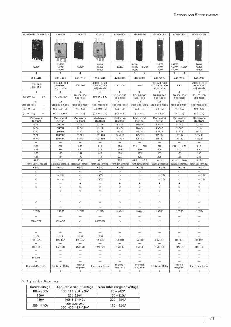
71
Type RXK125-S RXK125-H RX100 RXK250-S RXK250-H RG-225BN RG-225BH RX400 RX400B RG-400BN RG-400BH RX600B RF-600FN RX800B RF-800KN RF-1000KN RF-1000CBN RF-1200KN RF-1200CBN
Appearance
Phase- wiring Sysytem3ø3W1ø3W1ø2W
3ø3W1ø3W1ø2W
3ø4W3ø3W1ø3W1ø2W
3ø3W1ø3W1ø2W
3ø4W3ø3W1ø3W1ø2W
3ø3W1ø3W1ø2W
3ø4W3ø3W1ø3W1ø2W
3ø4W3ø3W1ø3W1ø2W
3ø4W3ø3W1ø3W1ø2W
3ø4W3ø3W1ø3W1ø2W
3ø3W1ø3W1ø2W
3ø4W3ø3W1ø3W1ø2W
Number of poles 3 3 4 3 3 4 3 3 4 3 4 3 4 3 4 3 3 4 3
Rated Voltage (AC V) 200 – 440 200 – 440 200 – 440 200 – 440 200 – 440 200 – 440 200 – 440(100 – 200) 200 – 440 200 – 440 200 – 440 440 (200) 200 – 440 440 (200) 440 (200) 440 (200) 440 (200) 440 (200)
Rated Current (A)(Base ambient temperature 40ºC)
15 20 30 40 50 63 75 100 125
16 20 30 40 50 63 75 100 125
5 10 15 20 30 40 50 60 75 100
125 150 175200 225 250
125 150 175200 225 250
125 150 175200 225
250 300350 400
200 / 225 / 250300 / 350 /400
adjustable
250 300350 400
300 / 350 /400500 / 600
adjustable500 600
400 /450 / 500600 / 700 / 800
adjustable700 800 1000
500 / 600 / 700800 / 900 / 1000
adjustable1200
600 / 700 / 8001000 / 1200adjustable
Rated Impulse withstand Voltage Uimp (kV) 8 8 8 8 8 8 8 8 8 8 8 8 8 8 8 8 8
High Speed Type
Rated Sensitivity Current (mA) 30100 ∙200 ∙500
30100 ∙200 ∙500
30100 ∙200 ∙500
30100 ∙200 ∙500
30100 ∙200 ∙500
100 ∙200∙500 30 (30)
100 ∙200 ∙500 (30)
100 ∙200 ∙500 100 ∙200 ∙500 30 100 ∙200 ∙500 50 ∙100 ∙200500 ∙1000 100 ∙200 ∙500 50 ∙100 ∙200
500 ∙100050 ∙100 ∙200500 ∙1000
50 ∙100 ∙200500 ∙1000
50 ∙100 ∙200500 ∙1000
50 ∙100 ∙200500 ∙1000
Operating time (sec. or less) 0.1 0.1 0.1 0.1 0.1 0.1 0.1 0.1 0.1 0.1 0.1 0.1 0.1 0.1 0.1 0.1 0.1
Time Delay Type
Rated Sensitivity Current (mA) (100 ∙200 ∙500 ) (100 ∙200 ∙500 ) (100 ∙200 ∙500 ) (100 ∙200 ∙500 ) (100 ∙200 ∙500 ) (100 ∙200 ∙500 ) — (100 ∙200 ∙500 ) (100 ∙200 ∙500 ) (100 ∙200 ∙500 ) — (100 ∙200 ∙500 ) (100 ∙200 ∙500 ) (100 ∙200 ∙500 ) (100 ∙200 ∙500 ) (100 ∙200 ∙500 ) (100 ∙200 ∙500 ) (100 ∙200 ∙500 ) (100 ∙200 ∙500 )
Operating time (sec. or less) (0.3 ∙ 0.6 ∙1.2) (0.3 ∙ 0.6 ∙1.2) (0.3 ∙ 0.6 ∙1.2) (0.3 ∙ 0.6 ∙1.2) (0.3 ∙ 0.6 ∙1.2) (0.3 ∙ 0.6 ∙1.2) — (0.3 ∙ 0.6 ∙1.2) (0.3 ∙ 0.6 ∙1.2) (0.3 0.6 1.2) — (0.3 0.6 1.2) (0.3 1.2) (0.3 0.6 1.2) (0.3 1.2) (0.3 1.2) (0.5 1.2) (0.3 1.2) (0.5 1.2)
Limiting non-actuating time (sec. or more) (0.1 0.2 0.5) (0.1 0.2 0.5) (0.1 0.2 0.5) (0.1 0.2 0.5) (0.1 0.2 0.5) (0.1 0.2 0.5) — (0.1 0.2 0.5) (0.1 0.2 0.5) (0.1 0.2 0.5) — (0.1 0.2 0.5) (0.1 0.5) (0.1 0.2 0.5) (0.1 0.5) (0.1 0.5) (0.2 0.5) (0.1 0.5) (0.2 0.5)
Indication of Earth Leakage Mechanical(button)
Mechanical(button)
Mechanical(button)
Mechanical(button)
Mechanical(button)
Mechanical(button)
Mechanical(button)
Mechanical(button)
Mechanical(button)
Mechanical(button)
Mechanical(button)
Mechanical(button)
Mechanical(button)
Mechanical(button)
Mechanical(button)
Mechanical(button)
Mechanical(button)
Rated Breaking
Capacity (kA)
JIS C 8201-2-2Ann2
(Icu/Ics)AC
440V 30 / 15 50 / 25 50 / 25 30 / 15 50 / 25 42 / 21 50 / 50 50 / 50 42 / 21 50 / 50 42 / 21 50 / 50 85 / 22 85 / 22 85 / 22 85 / 22 85 / 22
415V 30 / 15 50 / 25 50 / 25 30 / 15 50 / 25 42 / 21 50 / 50 50 / 50 42 / 21 50 / 50 42 / 21 50 / 50 85 / 22 85 / 22 85 / 22 85 / 22 85 / 22
400V 30 / 15 50 / 25 50 / 25 30 / 15 50 / 25 42 / 21 50 / 50 50 / 50 42 / 21 50 / 50 42 / 21 50 / 50 85 / 22 85 / 22 85 / 22 85 / 22 85 / 22
240V 50 / 25 100 / 50 85 /43 50 / 25 100 / 50 85 /43 100 / 100 100 / 100 85 /43 100 / 100 85 /43 100 / 100 125 / 32 125 / 32 125 / 32 125 / 32 125 / 32
200V 50 / 25 100 / 50 85 /43 50 / 25 100 / 50 85 /43 100 / 100 100 / 100 85 /43 100 / 100 85 /43 100 / 100 125 / 32 125 / 32 125 / 32 125 / 32 125 / 32
100V — — — — — — — — — — — — — — — — —
Dimensions (mm)
a 90 90 120 105 105 185 140 140 185 210 280 210 280 210 280 210 210 280 210
b 150 150 150 165 165 345 275 275 345 274 580 274 800 800 800 800 800
c 68 68 103 68 68 103 103 103 103 103 141 103 185 185 185 185 185
d 94 94 123 95 95 133 133 133 133 141 179 141 225 225 225 225 225
Net Weight (kg) 2.1 2.1 2.8 2.0 2.0 9.3 6.6 6.6 10.2 10.6 23.0 12.9 50.0 41.0 60.0 41.0 41.0 60.0 41.0
Standard Connection Type Front Terminal Front Terminal Front Terminal Front Terminal Front Terminal Front Terminal Front Bar Terminal Front Bar Terminal Front Bar Terminal Front Bar Terminal Front Bar Terminal Front Bar Terminal Front Bar Terminal Front Bar Terminal Front Bar Terminal Front Bar Terminal Front Bar Terminal
Phase Separator for Line Side ● (*2) ● (*2) ○ ● (*2) ● (*2) ● (*2) ● (*2) ● (*2) ● (*2) ● (*2) ● (*2) ● (*2) ● (*2) ● (*2) ● (*2) ● (*2) ● (*2)
Interior Accessories
Test Button Lead Wire TBL ○ ○ ○ ○ ○ ○ ○ ○ ○ ○ ○ ○ ○ ○ ○ ○ ○
Alarm Switch AL ○ (*3) ○ (*3) ○ ○ (*3) ○ (*3) ○ ○ ○ (*3) ○ ○ (*3) ○ ○ (*3) ○ ○ ○ (*3) ○ ○ (*3)
Auxiliary Switch AUX ○ (*3) ○ (*3) ○ ○ (*3) ○ (*3) ○ ○ ○ (*3) ○ ○ (*3) ○ ○ (*3) ○ ○ ○ (*3) ○ ○ (*3)
Earth Leakage Alarm Sw. EAL — — — — — — — — — — ● — ● ● ● ● ●
Terminal BlockTB ○ ○ ○ ○ ○ ○ ○ ○ ○ ○ ○ ○ ○ ○ ○ ○ ○
TB2 ○ ○ ○ ○ ○ — ○ ○ — ○ ○ ○ ○ ○ ○ ○ ○
Exterior Accessories
Rear-connecting StudSTB STB-2S
(Up to 50A)STB-2S
(Up to 50A) ○ — — — — — — — — — — — — — —
BSD BSD-3S(60A or more)
BSD-3S(60A or more) — ○ ○ ○ ○ ○ ○ ○ ○ ○ ○ ○ ○ ○ ○
Flush Mounting Base Assembly
GKW (STB) ○ (Up to 50A) ○ (Up to 50A) ○ — — — — — — — — — — — — — —
GK∙GKW (BSD) ○ (60A or more) ○ (60A or more) — ○ ○ ○ (GK) ○ ○ ○ (GK) ○ (GK) ○ (GK) ○ (GK) ○ (GK) ○ (GK) ○ (GK) ○ (GK) ○ (GK)
Plug-in Mounting Base Assembly PK ○ ○ — — — — — — — — — — — — — — —
Mechanical Interlock MIW MIW-3H MIW-3H MIW-3F MIW-4M MIW-4M MIW-5DE ○ MIW-5F MIW-5DE MIW-5G ○ MIW-5G ○ ○ ○ ○ ○
Motor-operating Mechanism
MMK-S — — — — — — — — — — — — — — — — —
MMK-C — — — — — — — — — — — — — — — — —
Lock Cover LC ○ ○ LC-2C LC-4J LC-4J — — — — — — — — — — — —
Handle Lock HL ○ ○ ○ HL-4J HL-4J HL-5 HL-5 HL-5 HL-5 HL-6 HL-6 HL-6 ○ ○ ○ ○ ○
Handle Operating Mechanism
HA — — HA-106 HA-210 HA-210 HA-405 HA-405 HA-406 HA-405 HA-402 HA-402 HA-402 HA-801 HA-801 HA-801 HA-801 HA-801
HM HM-S13 HM-S13 HM-S11 HM-S25 HM-S25 — — — — — — — — — — — —
Terminal Cover
Front Type
TMC TMC-2C TMC-2C TMC-3C TMC-4J TMC-4J TMC-5B TMC-5B TMC-5B TMC-5B TMC-5D TMC-5D TMC-5D TMC-6 TMC-6 TMC-6B TMC-6 TMC-6B
Short type — — — TMC-4JS TMC-4JS — — — — — — — — — — — —
Long type — — — — — — — — — — — — — — — — —
Rear Type BTC BTC-2C BTC-2C BTC-3C BTC-4J BTC-4J BTC-5B BTC-5B BTC-5B BTC-5B — — — — — — — —
IEC Rail 35 mm — — — — — — — — — — — — — — — — —
Automatic Tripping Device Thermal-Magnetic
Thermal-Magnetic Full Magnetic Thermal-
MagneticThermal-Magnetic Thermal-Magnetic Thermal-
MagneticElectronic
Relay Thermal-Magnetic Electronic Relay Thermal-Magnetic Electronic Relay Thermal-
MagneticThermal-Magnetic Electronic Relay Thermal-
Magnetic Electronic Relay
Trip Button ● ● — ● ● — — ● — — ● ● ● ● ● ● ● ●
Rated voltage Applicable circuit voltage Permissible range of voltage 100 – 200V 100 ∙110 ∙200 ∙220V 80 – 242V
200V 200 ∙220V 160 – 220V440V 400 ∙415 ∙440V 320 – 484V
200 – 440V 200 ∙220 ∙240380 ∙400 ∙415 ∙440V 160 – 484V
Ratings and specifications
9. Applicable voltage range
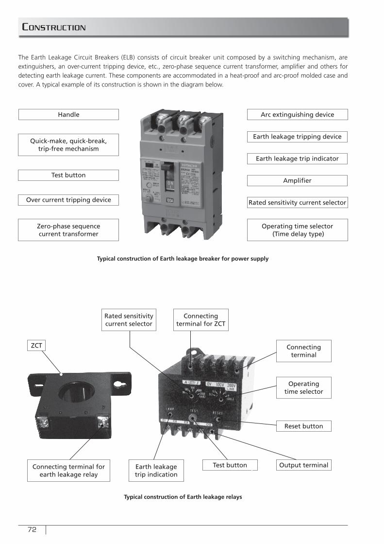
72
constRUction
The Earth Leakage Circuit Breakers (ELB) consists of circuit breaker unit composed by a switching mechanism, are extinguishers, an over-current tripping device, etc., zero-phase sequence current transformer, amplifi er and others for detecting earth leakage current. These components are accommodated in a heat-proof and arc-proof molded case and cover. A typical example of its construction is shown in the diagram below.
Handle Arc extinguishing device
Quick-make, quick-break, trip-free mechanism
Earth leakage tripping device
Earth leakage trip indicator
Amplifi er
Rated sensitivity current selector
Operating time selector (Time delay type)
Test button
Over current tripping device
Zero-phase sequence current transformer
Typical construction of Earth leakage breaker for power supply
Typical construction of Earth leakage relays
ZCT
Connecting terminal forearth leakage relay
Connecting terminal for ZCT
Connecting terminal
Rated sensitivity current selector
Earth leakage trip indication
Reset button
Operating time selector
Output terminalTest button
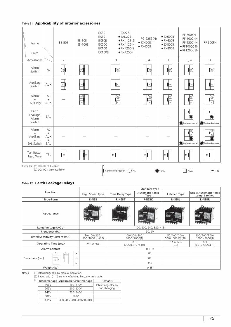
73
Table 21 Applicability of interior accessories
Table 22 Earth Leakage Relays
Frame EB-50EEB-50EEB-100E
EX30EX50EX50BEX50CEX100EX100B
EX225✶EXK225✶RXK125-S✶RXK125-H✶RXK250-S✶RXK250-H
RG-225B (N)✶EX400B✶RX400B
✶EX600B✶RX600B✶EX800B✶RX800B
RF-800KNRF-1000KNRF-1200KN
✶RF1000CBN✶RF1200CBN
RF-600FN
Poles
Accessories 2 3 3 3, 4 3 3, 4 3
Alarm Switch
AL
Auxiliary Switch
AUX
Alarm +
Auxiliary
AL+
AUX—
Earth Leakage Alarm Switch
EAL — — — — —
Alarm +
Auxiliary +
EAL Switch
AL+
AUX+
EAL
— — — — —
Test Button Lead Wire
TBL
1C
1C
1C 2C 2C 2C1C
1C 1C 2C1C 2C 2C
2C
2C
1C
1C
1C
2C
2C
1C
2C
1C
1C
2C
2C
1C
2C
Equipped normaly Equipped normaly
1C
2C
Equipped normaly Equipped normaly
Handle of Breaker AL AUXEAL TBL
Remarks: (1) Handle of breaker (2) 2C: 1C is also available
Notes: (1) Interchangeable by manual operation. (2) Rating with ( ) are manufactured by customer’s order. (3)
FunctionStandard type
High Speed Type Time Delay Type Automatic Reset Type Latched Type Relay: Automatic Reset
Lamp: LatchedType-Form R-NZB R-NZBT R-NZBK R-NZBL R-NZBR
Appearance
Rated Voltage (AC V) 100, 200, 240, 380, 415Frequency (Hz) 50, 60
Rated Sensitivity Current (mA) 50 /100 / 200 /500 /1000 (1) (30)
100 / 200 / 500 /1000 / 2000(1)
50 /100 / 200 /500 /1000 (1) (30)
100 / 200 / 500 /1000 / 2000(1)
Operating Time (sec.) 0.1 or less 0.3 (0.2 / 0.5 / 2 /4 (1))
0.1 or less0.3
0.3 (0.2 / 0.5 / 2 /4 (1))
Alarm Contact 1c + 1a
Dimensions (mm)
a 80
b 80
c 115
Weight (kg) 0.45
a
b
dc
Rated Voltage Applicable Circuit Voltage Remarks100V 100∙110V Interchangealbe by
tap changing200V 200∙220V240V 230∙240V380V 380V415V 400∙415 ∙440 ∙460V (60Hz)
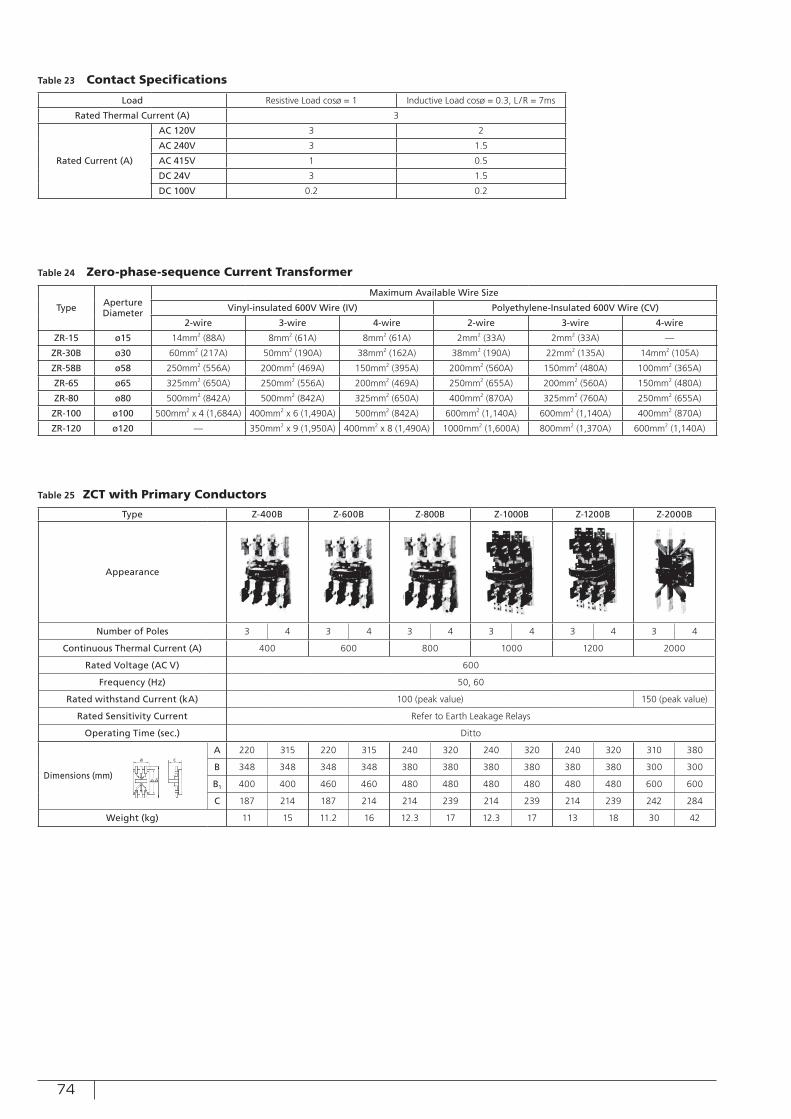
74
Table 23 Contact Specifications
Table 24 Zero-phase-sequence Current Transformer
Table 25 ZCT with Primary Conductors
Load Resistive Load cosø = 1 Inductive Load cosø = 0.3, L /R = 7ms
Rated Thermal Current (A) 3
Rated Current (A)
AC 120V 3 2
AC 240V 3 1.5
AC 415V 1 0.5
DC 24V 3 1.5
DC 100V 0.2 0.2
Type Aperture Diameter
Maximum Available Wire Size
Vinyl-insulated 600V Wire (IV) Polyethylene-Insulated 600V Wire (CV)
2-wire 3-wire 4-wire 2-wire 3-wire 4-wire
ZR-15 ø15 14mm2 (88A) 8mm2 (61A) 8mm2 (61A) 2mm2 (33A) 2mm2 (33A) —
ZR-30B ø30 60mm2 (217A) 50mm2 (190A) 38mm2 (162A) 38mm2 (190A) 22mm2 (135A) 14mm2 (105A)
ZR-58B ø58 250mm2 (556A) 200mm2 (469A) 150mm2 (395A) 200mm2 (560A) 150mm2 (480A) 100mm2 (365A)
ZR-65 ø65 325mm2 (650A) 250mm2 (556A) 200mm2 (469A) 250mm2 (655A) 200mm2 (560A) 150mm2 (480A)
ZR-80 ø80 500mm2 (842A) 500mm2 (842A) 325mm2 (650A) 400mm2 (870A) 325mm2 (760A) 250mm2 (655A)
ZR-100 ø100 500mm2 x 4 (1,684A) 400mm2 x 6 (1,490A) 500mm2 (842A) 600mm2 (1,140A) 600mm2 (1,140A) 400mm2 (870A)
ZR-120 ø120 — 350mm2 x 9 (1,950A) 400mm2 x 8 (1,490A) 1000mm2 (1,600A) 800mm2 (1,370A) 600mm2 (1,140A)
Type Z-400B Z-600B Z-800B Z-1000B Z-1200B Z-2000B
Appearance
Number of Poles 3 4 3 4 3 4 3 4 3 4 3 4
Continuous Thermal Current (A) 400 600 800 1000 1200 2000
Rated Voltage (AC V) 600
Frequency (Hz) 50, 60
Rated withstand Current (kA) 100 (peak value) 150 (peak value)
Rated Sensitivity Current Refer to Earth Leakage Relays
Operating Time (sec.) Ditto
Dimensions (mm)
A 220 315 220 315 240 320 240 320 240 320 310 380
B 348 348 348 348 380 380 380 380 380 380 300 300
B1 400 400 460 460 480 480 480 480 480 480 600 600
C 187 214 187 214 214 239 214 239 214 239 242 284
Weight (kg) 11 15 11.2 16 12.3 17 12.3 17 13 18 30 42
a c
b b1
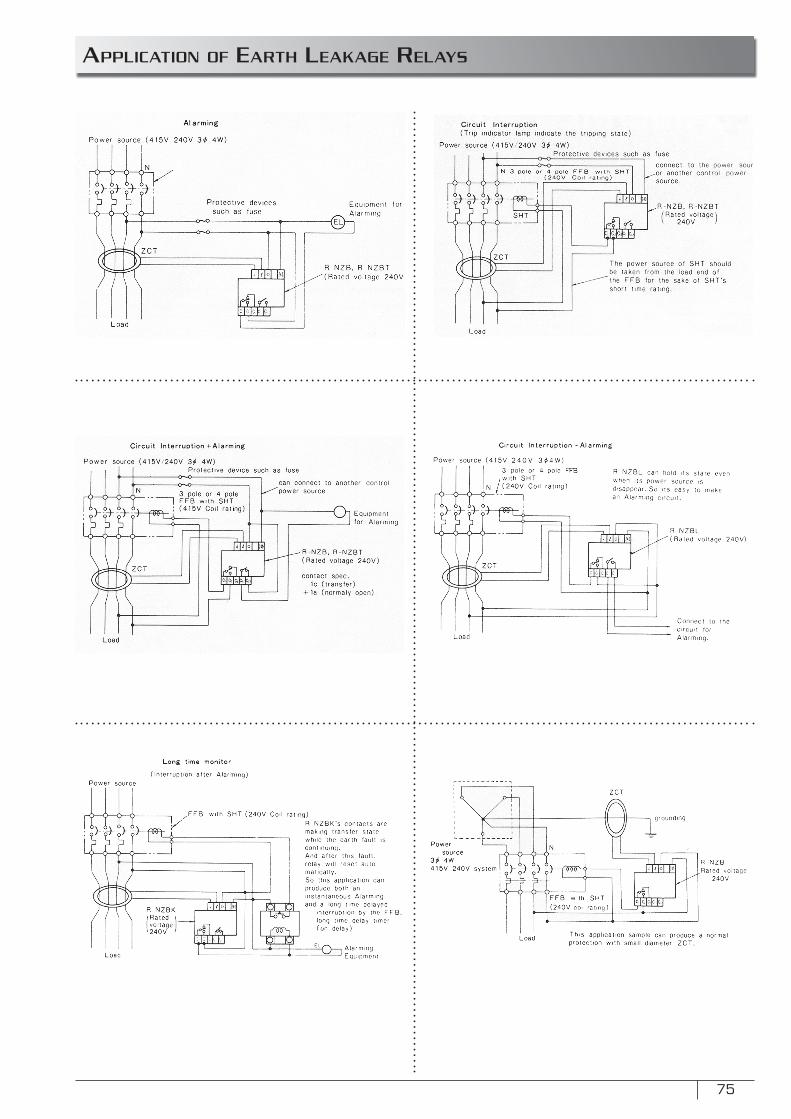
75
appLication of eaRtH LeaKage ReLaYs
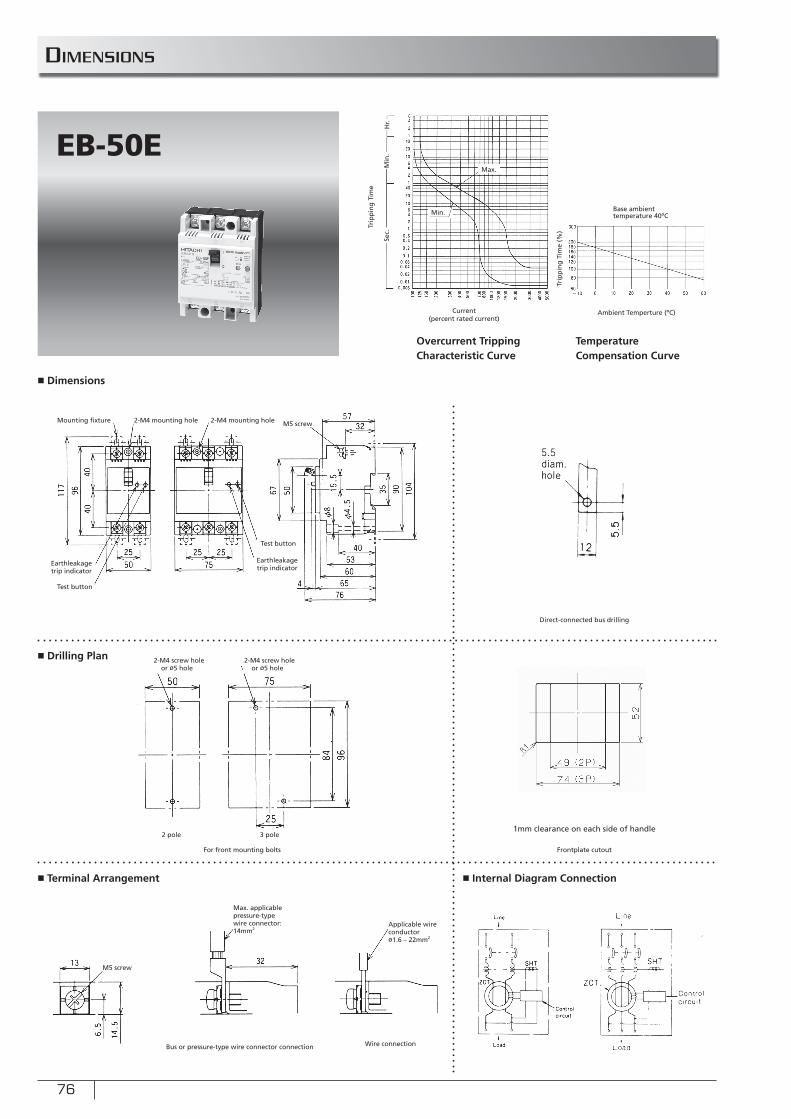
76
■ Dimensions
■ Drilling Plan
■ Terminal Arrangement ■ Internal Diagram Connection
EB-50E
Min.
Max.
Sec.
Min
.H
r.
Ambient Temperture (ºC)Current (percent rated current)
Trip
pin
g T
ime
(%)
Trip
pin
g T
ime
Overcurrent Tripping Characteristic Curve
Temperature Compensation Curve
Base ambient temperature 40ºC
For front mounting bolts
Direct-connected bus drilling
Frontplate cutout
Mounting fi xture
Test button
2-M4 mounting hole M5 screw2-M4 mounting hole
Test button
Earthleakage trip indicator
Earthleakage trip indicator
2-M4 screw hole or ø5 hole
2 pole 3 pole
2-M4 screw hole or ø5 hole
1mm clearance on each side of handle
M5 screw
Wire connection
Max. applicable pressure-typewire connector: 14mm2
Bus or pressure-type wire connector connection
Applicable wire conductorø1.6 – 22mm2
diMensions
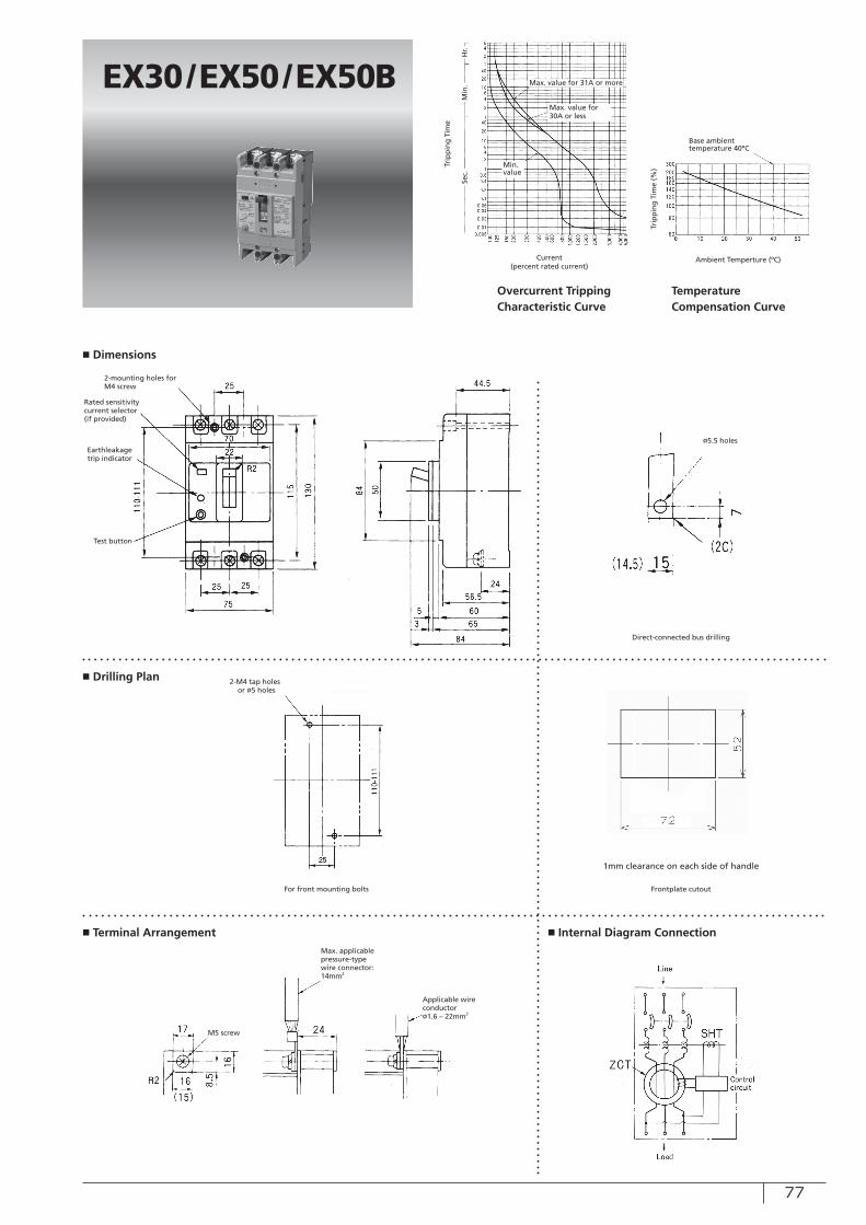
77
■ Dimensions
■ Drilling Plan
■ Terminal Arrangement ■ Internal Diagram Connection
EX30/EX50/EX50B
Sec.
Min
.H
r.
Ambient Temperture (ºC)Current (percent rated current)
Trip
pin
g T
ime
(%)Tr
ipp
ing
Tim
e
Overcurrent Tripping Characteristic Curve
Temperature Compensation Curve
Base ambient temperature 40ºC
For front mounting bolts
Direct-connected bus drilling
Frontplate cutout
Test button
2-mounting holes for M4 screw
Rated sensitivity current selector (if provided)
Earthleakage trip indicator
1mm clearance on each side of handle
M5 screw
Min. value
ø5.5 holes
2-M4 tap holes or ø5 holes
Max. applicable pressure-typewire connector: 14mm2
Applicable wire conductorø1.6 – 22mm2
Max. value for 31A or more
Max. value for 30A or less
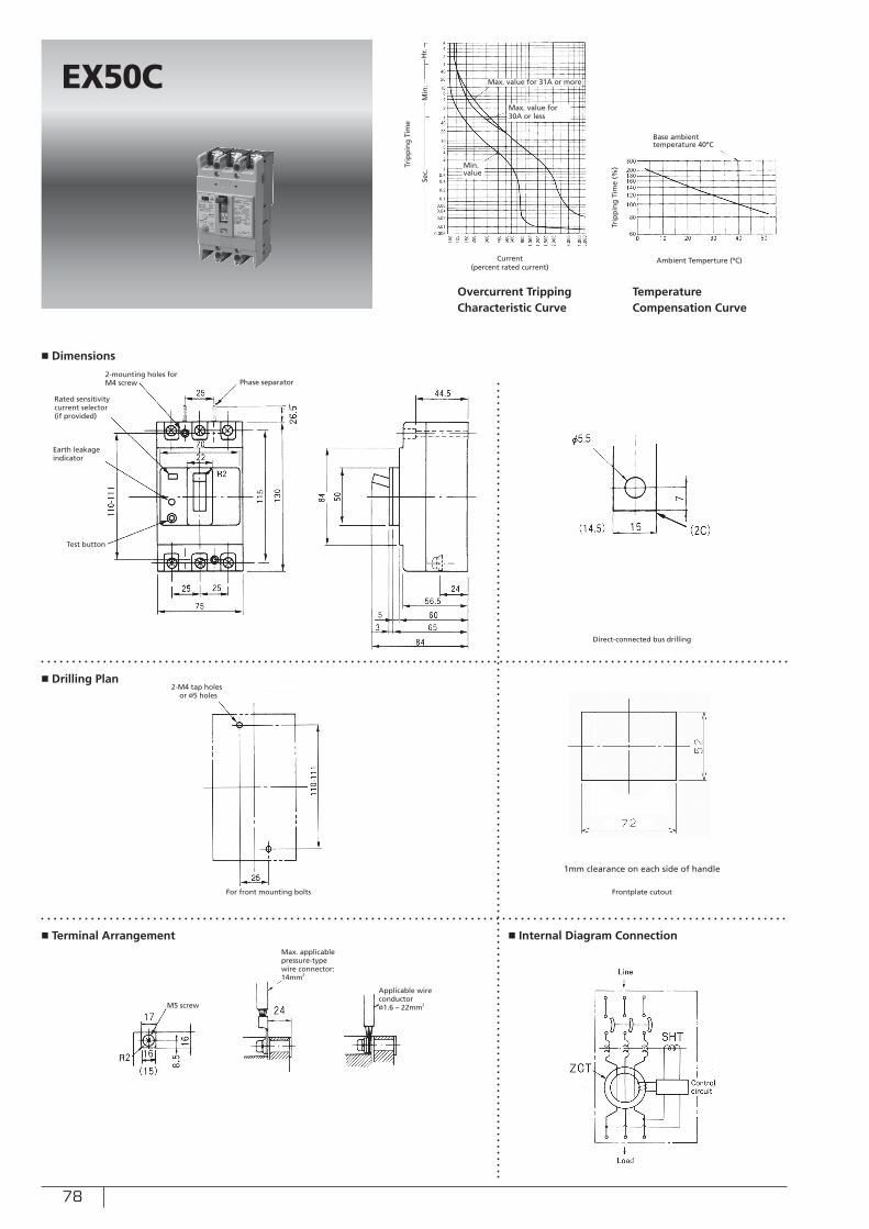
78
■ Dimensions
■ Drilling Plan
■ Terminal Arrangement ■ Internal Diagram Connection
EX50C
Sec.
Min
.H
r.
Ambient Temperture (ºC)Current (percent rated current)
Trip
pin
g T
ime
(%)Tr
ipp
ing
Tim
e
Overcurrent Tripping Characteristic Curve
Temperature Compensation Curve
Base ambient temperature 40ºC
For front mounting bolts
Direct-connected bus drilling
Frontplate cutout
Test button
2-mounting holes for M4 screw
Rated sensitivity current selector (if provided)
Earth leakage indicator
1mm clearance on each side of handle
M5 screw
Min. value
2-M4 tap holes or ø5 holes
Phase separator
Max. applicable pressure-typewire connector: 14mm2
Applicable wire conductorø1.6 – 22mm2
Max. value for 31A or more
Max. value for 30A or less
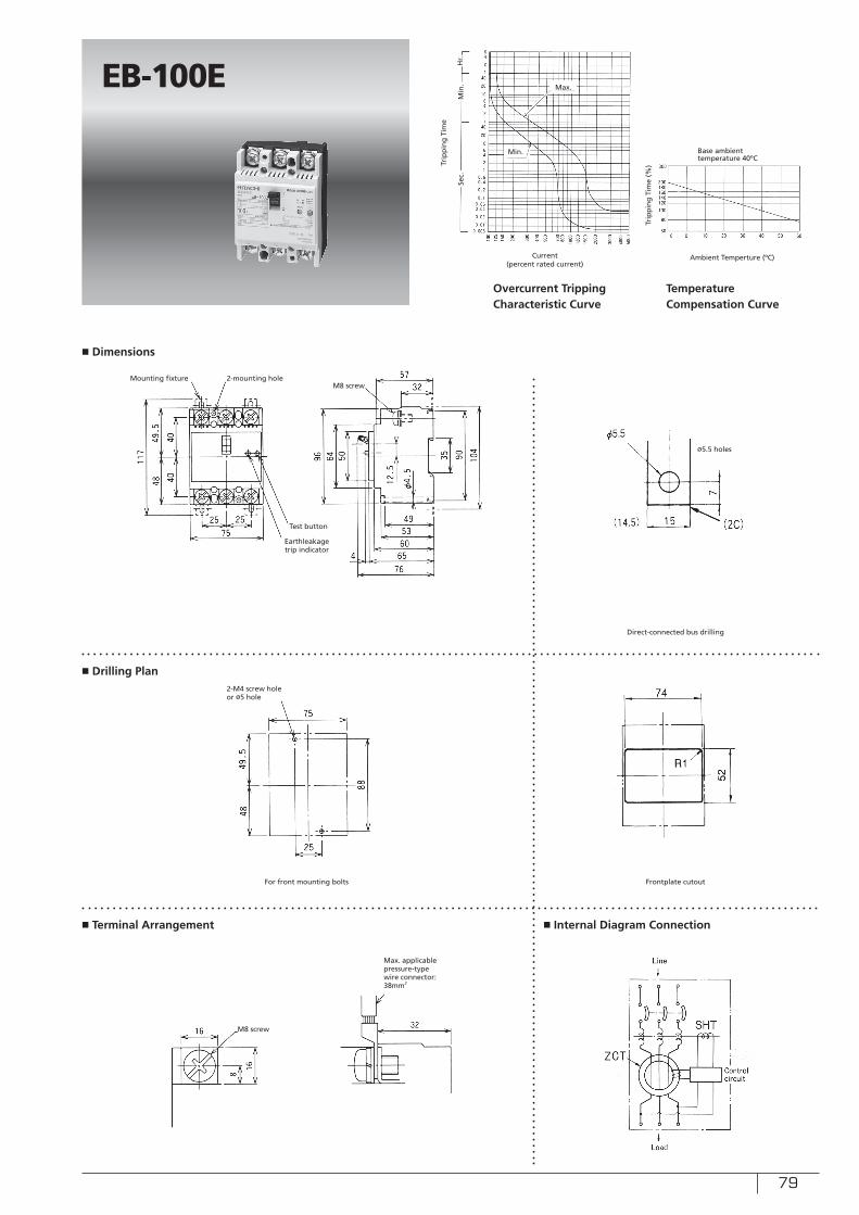
79
■ Dimensions
■ Drilling Plan
■ Terminal Arrangement ■ Internal Diagram Connection
EB-100E
Sec.
Min
.H
r.
Ambient Temperture (ºC)Current (percent rated current)
Trip
pin
g T
ime
(%)Tr
ipp
ing
Tim
e
Overcurrent Tripping Characteristic Curve
Temperature Compensation Curve
Base ambient temperature 40ºC
For front mounting bolts
Direct-connected bus drilling
Frontplate cutout
Test button
2-mounting hole
Earthleakage trip indicator
M8 screw
Min.
Max.
ø5.5 holes
2-M4 screw hole or ø5 hole
Mounting fixtureM8 screw
Max. applicable pressure-typewire connector: 38mm2
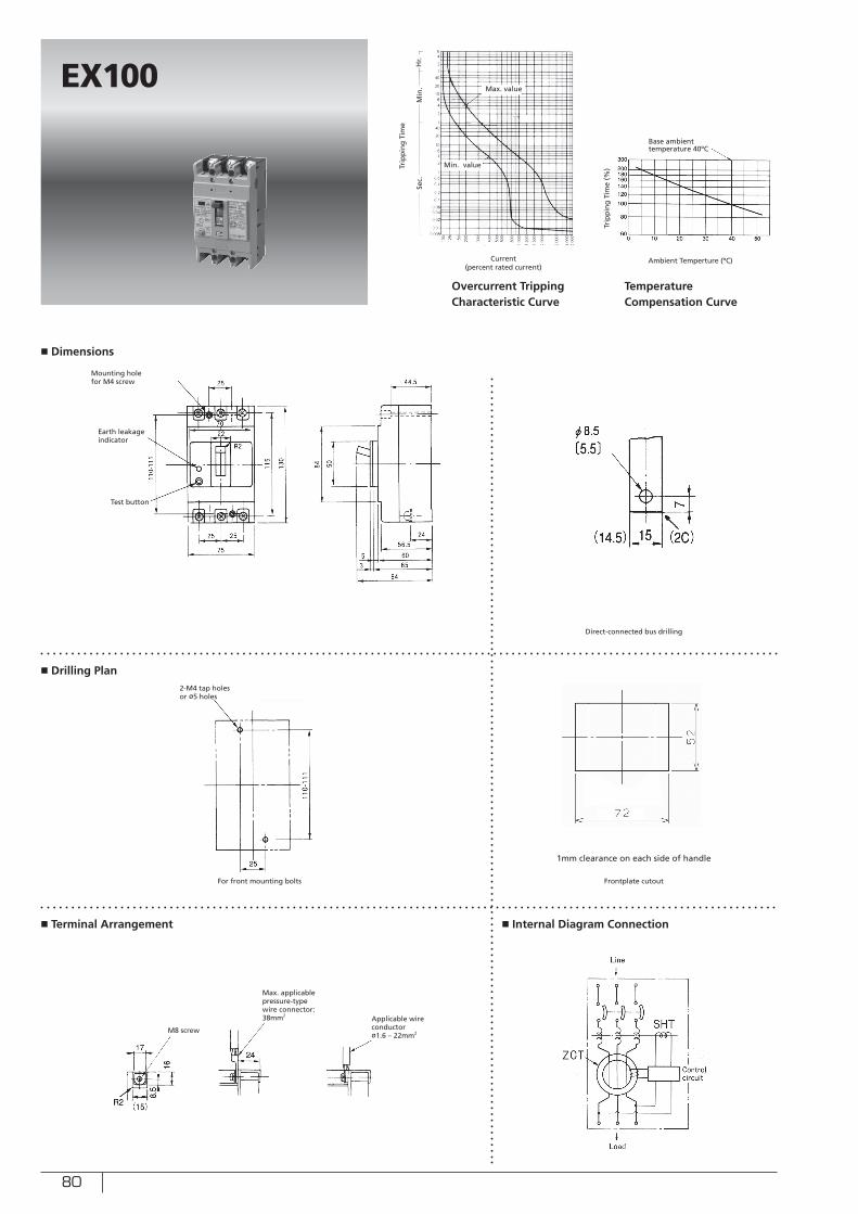
80
■ Dimensions
■ Drilling Plan
■ Terminal Arrangement ■ Internal Diagram Connection
EX100
Sec.
Min
.H
r.
Ambient Temperture (ºC)Current (percent rated current)
Trip
pin
g T
ime
(%)Tr
ipp
ing
Tim
e
Overcurrent Tripping Characteristic Curve
Temperature Compensation Curve
Base ambient temperature 40ºC
For front mounting bolts
Direct-connected bus drilling
Frontplate cutout
Test button
Min. value
Mounting hole for M4 screw
2-M4 tap holes or ø5 holes
1mm clearance on each side of handle
Earth leakage indicator
Max. value
M8 screw
Max. applicable pressure-typewire connector: 38mm2
Applicable wire conductorø1.6 – 22mm2

81
■ Dimensions
■ Drilling Plan
■ Terminal Arrangement ■ Internal Diagram Connection
EX100B
Sec.
Min
.H
r.
Ambient Temperture (ºC)Current (percent rated current)
Trip
pin
g T
ime
(%)Tr
ipp
ing
Tim
e
Overcurrent Tripping Characteristic Curve
Temperature Compensation Curve
Base ambient temperature 40ºC
For front mounting bolts
Direct-connected bus drilling
Frontplate cutout
Test button
M8 screw
Min. value
Max. applicable pressure-typewire connector: 38mm2
Max. value
Mounting hole for M4 screw
Earthleakage trip indicator
2-M4 tap holes or ø5 holes
1mm clearance on each side of handle
Applicable wire conductorø1.6 – 22mm2
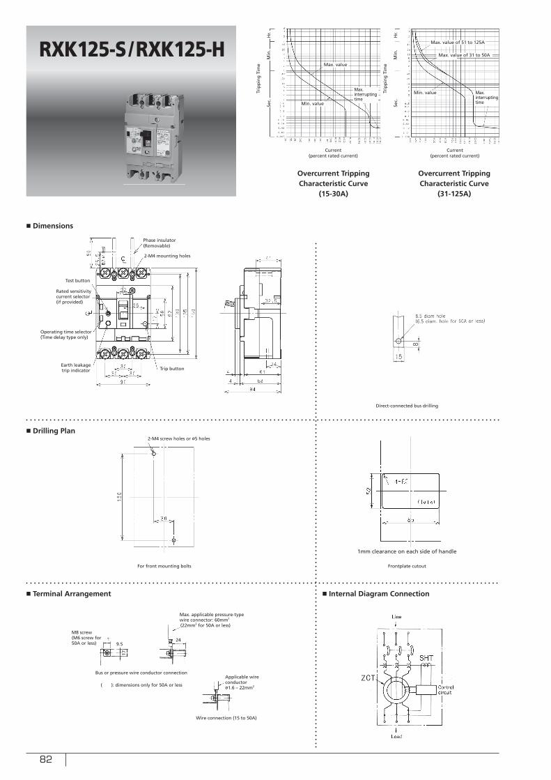
82
■ Dimensions
■ Drilling Plan
■ Terminal Arrangement
RXK125-S/RXK125-H
17
249.5
For front mounting bolts
Max. applicable pressure-typewire connector: 60mm2
(22mm2 for 50A or less)
M8 screw(M6 screw for 50A or less)
Bus or pressure wire conductor connection
Wire connection (15 to 50A)
( ): dimensions only for 50A or less
■ Internal Diagram Connection
Direct-connected bus drilling
Frontplate cutout
1mm clearance on each side of handle
Test button
2-M4 mounting holes
Earth leakage trip indicator
Rated sensitivity current selector (if provided)
Phase insulator(Removable)
Applicable wire conductorø1.6 – 22mm2
Trip button
Operating time selector(Time delay type only)
2-M4 screw holes or ø5 holes
Max. value
Sec.
Sec.
Min
.
Min
.
Hr.
Hr.
Current (percent rated current)
Current (percent rated current)
Trip
pin
g T
ime
Trip
pin
g T
ime
Overcurrent Tripping Characteristic Curve
(15-30A)
Overcurrent Tripping Characteristic Curve
(31-125A)
Min. value
Max. interrupting time
Min. value Max. interrupting time
Max. value of 31 to 50A
Max. value of 51 to 125A
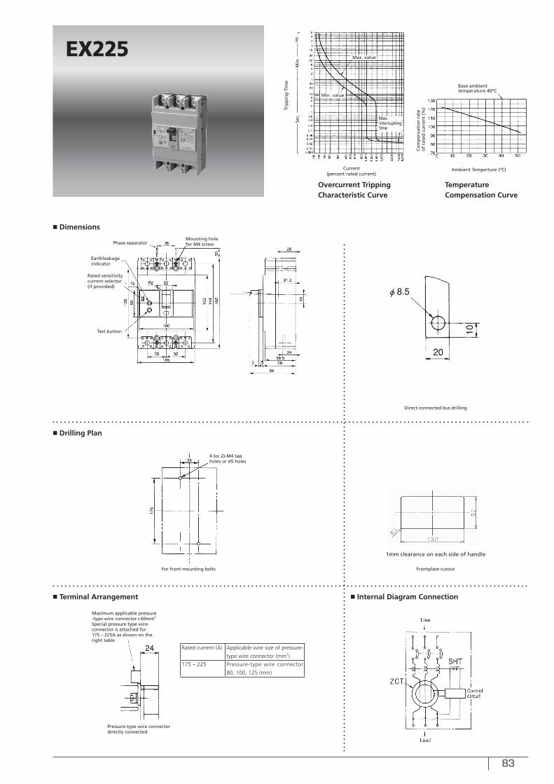
83
■ Dimensions
■ Drilling Plan
■ Terminal Arrangement ■ Internal Diagram Connection
EX225
Sec.
Min
.H
r.
Ambient Temperture (ºC)Current (percent rated current)
Co
mp
ensa
tio
n r
ate
of
rate
d c
urr
ent
(%)Tr
ipp
ing
Tim
e
Overcurrent Tripping Characteristic Curve
Temperature Compensation Curve
Base ambient temperature 40ºC
For front mounting bolts
Direct-connected bus drilling
Frontplate cutout
Test button
Mounting hole for M4 screw
Earthleakage indicator
4 (or 2)-M4 tap holes or ø5 holes
1mm clearance on each side of handle
Maximum applicable pressure -type wire connector=60mm2
Special pressure type wire connector is attached for 175 – 225A as shown on the right table
Pressure-type wire connector directly connected
Rated current (A) Applicable wire size of pressure-
type wire connector (mm2)
175 – 225 Pressure-type wire connector
80, 100, 125 (mm)
Min. value
Max. value
Max. interrupting time
Rated sensitivity current selector (if provided)
Phase separator
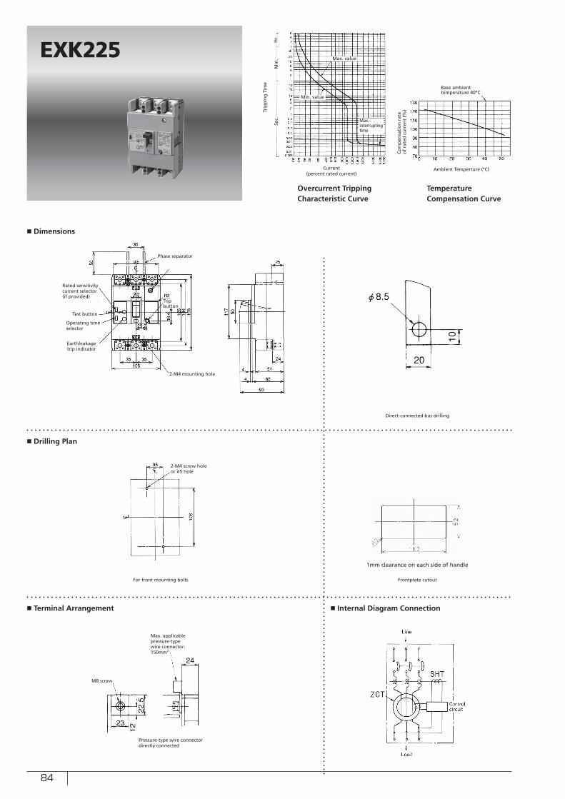
84
■ Dimensions
■ Drilling Plan
■ Terminal Arrangement ■ Internal Diagram Connection
EXK225
Sec.
Min
.H
r.
Ambient Temperture (ºC)Current (percent rated current)
Trip
pin
g T
ime
Overcurrent Tripping Characteristic Curve
Temperature Compensation Curve
Base ambient temperature 40ºC
For front mounting bolts
Direct-connected bus drilling
Frontplate cutout
Test button
2-M4 mounting hole
Earthleakage trip indicator
1mm clearance on each side of handle
Min. value
Max. value
Max. interrupting time
Rated sensitivity current selector (if provided)
Phase separator
Trip button
Operating time selector
2-M4 screw hole or ø5 hole
M8 screw
Max. applicable pressure-typewire connector: 150mm2
Pressure-type wire connector directly connected
Co
mp
ensa
tio
n r
ate
of
rate
d c
urr
ent
(%)
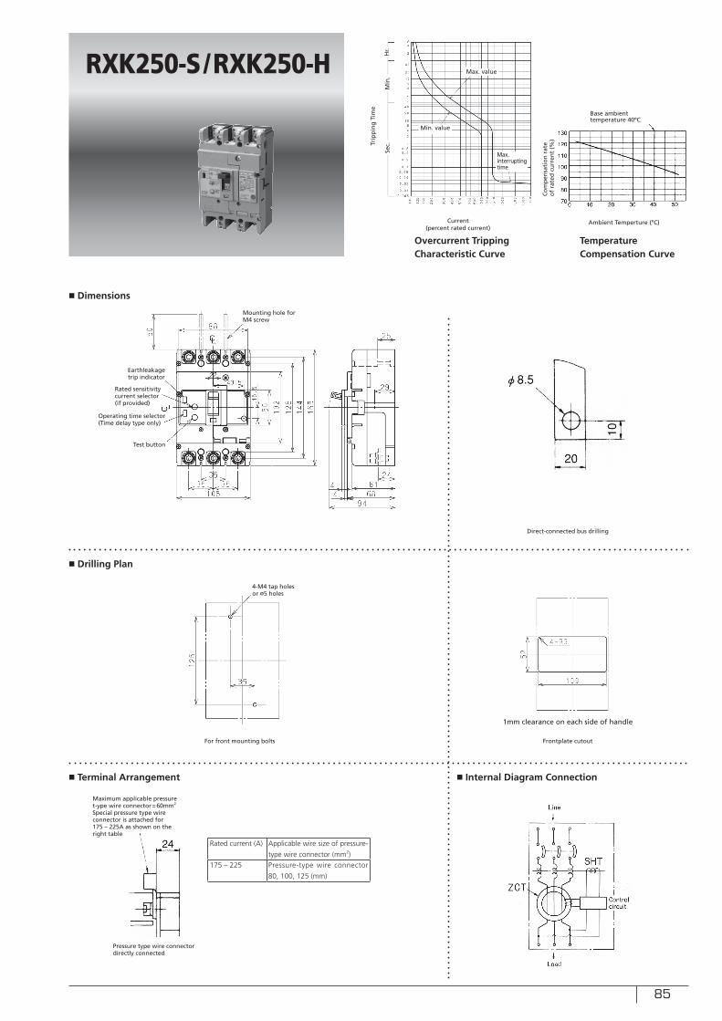
85
■ Dimensions
■ Drilling Plan
■ Terminal Arrangement ■ Internal Diagram Connection
RXK250-S/RXK250-H
Sec.
Min
.H
r.
Ambient Temperture (ºC)Current (percent rated current)
Co
mp
ensa
tio
n r
ate
of
rate
d c
urr
ent
(%)
Trip
pin
g T
ime
Overcurrent Tripping Characteristic Curve
Temperature Compensation Curve
Base ambient temperature 40ºC
For front mounting bolts
Direct-connected bus drilling
Frontplate cutout
Test button
Mounting hole for M4 screw
Earthleakage trip indicator
1mm clearance on each side of handle
Min. value
Max. value
Max. interrupting time
Rated sensitivity current selector (if provided)
Operating time selector(Time delay type only)
4-M4 tap holes or ø5 holes
Maximum applicable pressure t-ype wire connector=60mm2
Special pressure type wire connector is attached for 175 – 225A as shown on the right table
Pressure type wire connector directly connected
Rated current (A) Applicable wire size of pressure-
type wire connector (mm2)
175 – 225 Pressure-type wire connector
80, 100, 125 (mm)
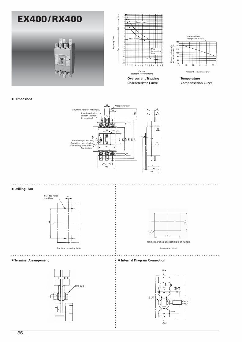
86
■ Dimensions
■ Drilling Plan
■ Terminal Arrangement ■ Internal Diagram Connection
EX400/RX400
Sec.
Min
.H
r.
Ambient Temperture (ºC)Current (percent rated current)
Co
mp
ensa
tio
n r
ate
of
rate
d c
urr
ent
(%)
Trip
pin
g T
ime
Overcurrent Tripping Characteristic Curve
Temperature Compensation Curve
Base ambient temperature 40ºC
For front mounting bolts Frontplate cutout
Test button
Earthleakage indicator
1mm clearance on each side of handle
Min. value
Max. value
Max. interrupting time
Rated sensitivity current selector (if provided)
Phase separator
4-M4 tap holes or ø5 holes
M10 bolt
Mounting hole for M4 screw
Operating time selector(Time delay type only)
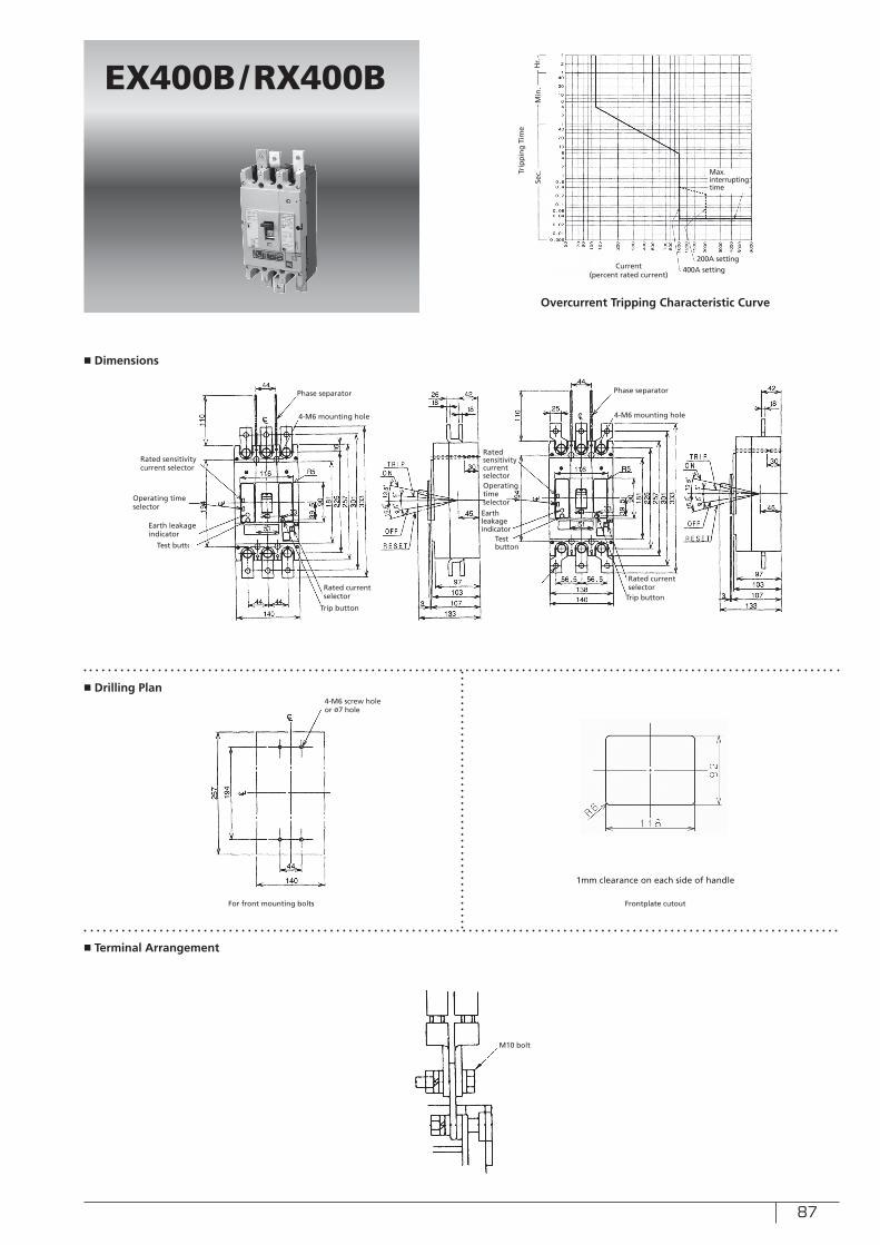
87
■ Dimensions
■ Drilling Plan
■ Terminal Arrangement
EX400B/RX400B
Sec.
Min
.H
r.
Current (percent rated current)
Trip
pin
g T
ime
Overcurrent Tripping Characteristic Curve
For front mounting bolts Frontplate cutout
Test button
1mm clearance on each side of handle
Max. interrupting time
4-M6 screw hole or ø7 hole
M10 bolt
200A setting400A setting
Phase separator
Trip button
Rated current selector
4-M6 mounting hole
Earth leakage indicator
Test button
Operating time selector
Phase separator
4-M6 mounting hole
Earth leakage indicator
Rated sensitivity current selector
Trip button
Rated current selector
Rated sensitivity current selector
Operating time selector
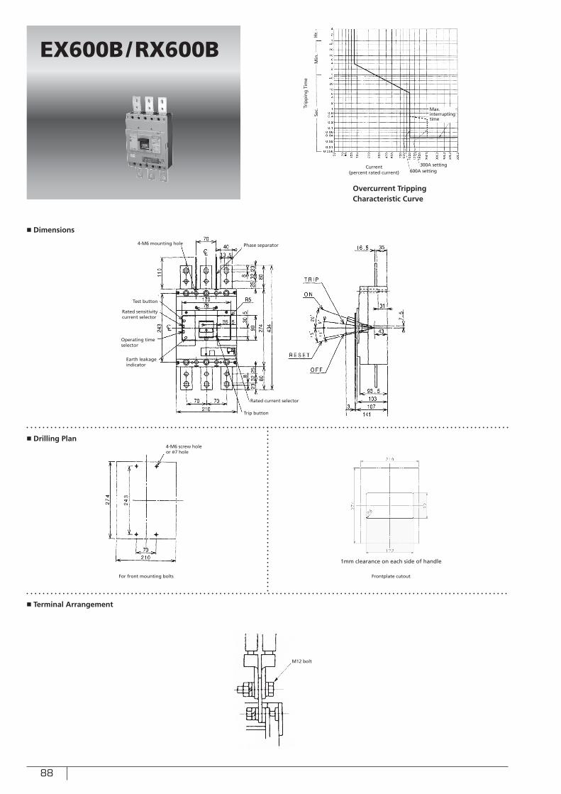
88
■ Dimensions
■ Drilling Plan
■ Terminal Arrangement
EX600B/RX600B
Sec.
Min
.H
r.
Current (percent rated current)
Trip
pin
g T
ime
Overcurrent Tripping Characteristic Curve
For front mounting bolts Frontplate cutout
Test button
1mm clearance on each side of handle
Max. interrupting time
Rated sensitivity current selector
Operating time selector
4-M6 screw hole or ø7 hole
M12 bolt
300A setting600A setting
Phase separator
Trip button
Rated current selector
4-M6 mounting hole
Earth leakage indicator
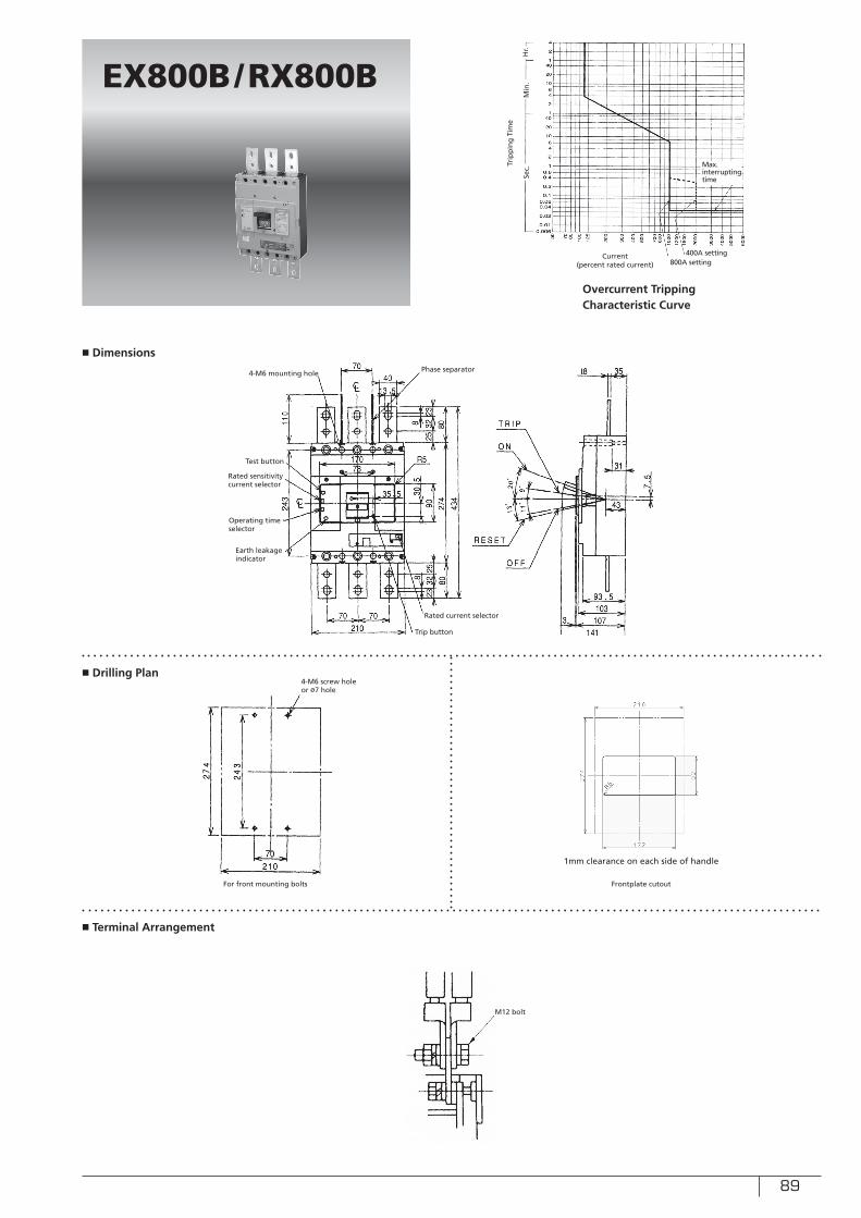
89
■ Dimensions
■ Drilling Plan
■ Terminal Arrangement
EX800B/RX800B
Sec.
Min
.H
r.
Current (percent rated current)
Trip
pin
g T
ime
Overcurrent Tripping Characteristic Curve
For front mounting bolts Frontplate cutout
Test button
1mm clearance on each side of handle
Max. interrupting time
Rated sensitivity current selector
Operating time selector
4-M6 screw hole or ø7 hole
M12 bolt
400A setting800A setting
Phase separator
Trip button
Rated current selector
4-M6 mounting hole
Earth leakage indicator
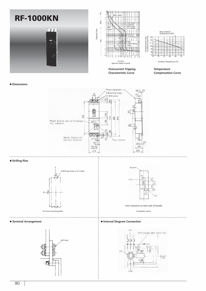
90
■ Dimensions
■ Drilling Plan
■ Terminal Arrangement ■ Internal Diagram Connection
RF-1000KN
Sec.
Min
.H
r.
Ambient Temperture (ºC)Current (percent rated current)
Co
mp
ensa
tio
n r
ate
of
rate
d c
urr
ent
(%)
Trip
pin
g T
ime
Overcurrent Tripping Characteristic Curve
Temperature Compensation Curve
Base ambient temperature 40ºC
For front mounting bolts Frontplate cutout
1mm clearance on each side of handle
Min. value
Max. value
4-M10 tap holes or ø11 holes
M12 bolt
Max. interrupting time
Adjustable magnetic trip range (in 4 steps)
Position of setting
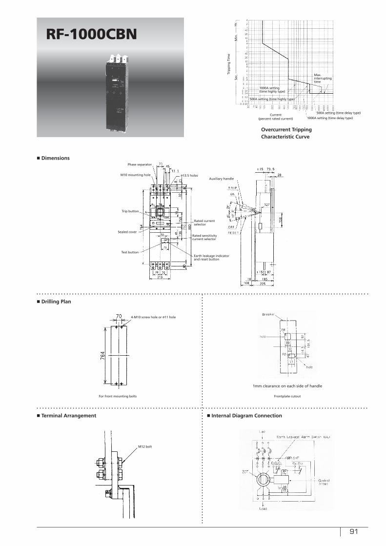
91
■ Dimensions
■ Drilling Plan
■ Terminal Arrangement ■ Internal Diagram Connection
RF-1000CBN
For front mounting bolts Frontplate cutout
1mm clearance on each side of handle
4-M10 screw hole or ø11 hole
M12 bolt
Sec.
Min
.H
r.
Current (percent rated current)
Trip
pin
g T
ime
Overcurrent Tripping Characteristic Curve
Max. interrupting time
500A setting (time delay type)
1000A setting (time delay type)
500A setting (time highly type)
1000A setting (time highly type)
Test button
Rated sensitivity current selector
Sealed cover
Phase separator
Trip button
Rated current selector
M10 mounting hole
Earth leakage indicator and reset button
Auxiliary handleø13.5 holes
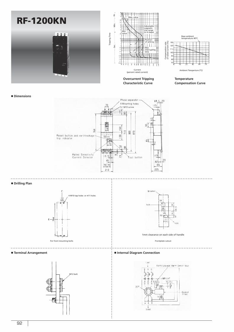
92
■ Dimensions
■ Drilling Plan
■ Terminal Arrangement ■ Internal Diagram Connection
RF-1200KN
Sec.
Min
.H
r.
Ambient Temperture (ºC)Current (percent rated current)
Co
mp
ensa
tio
n r
ate
of
rate
d c
urr
ent
(%)
Trip
pin
g T
ime
Overcurrent Tripping Characteristic Curve
Temperature Compensation Curve
Base ambient temperature 40ºC
For front mounting bolts Frontplate cutout
1mm clearance on each side of handle
Min. value
Max. value
4-M10 tap holes or ø11 holes
M12 bolt
Max. interrupting time
Adjustable magnetic trip range (in 4 steps)
Position of setting
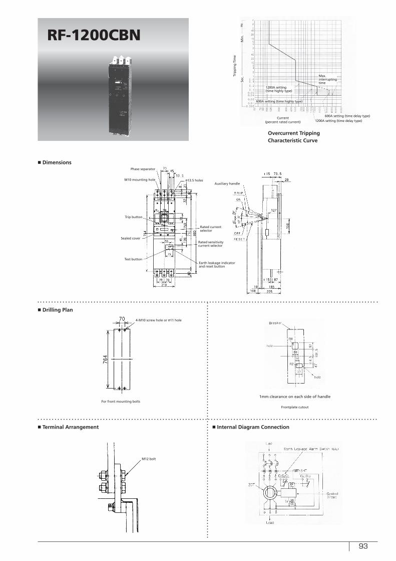
93
■ Dimensions
■ Drilling Plan
■ Terminal Arrangement ■ Internal Diagram Connection
RF-1200CBN
For front mounting bolts
Frontplate cutout
1mm clearance on each side of handle
4-M10 screw hole or ø11 hole
M12 bolt
Sec.
Min
.H
r.
Current (percent rated current)
Trip
pin
g T
ime
Overcurrent Tripping Characteristic Curve
Max. interrupting time
600A setting (time delay type)1200A setting (time delay type)
600A setting (time highly type)
1200A setting (time highly type)
Test button
Rated sensitivity current selector
Sealed cover
Phase separator
Trip button
Rated current selector
M10 mounting hole
Earth leakage indicator and reset button
Auxiliary handleø13.5 holes
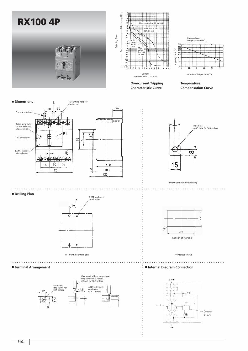
94
■ Dimensions
■ Drilling Plan
■ Terminal Arrangement ■ Internal Diagram Connection
RX100 4P
Sec.
Min
.H
r.
Ambient Temperture (ºC)Current (percent rated current)
Trip
pin
g T
ime
(%)Tr
ipp
ing
Tim
e
Overcurrent Tripping Characteristic Curve
Temperature Compensation Curve
Base ambient temperature 40ºC
For front mounting bolts
Direct-connected bus drilling
Frontplate cutout
Test button
Mounting hole for M4 screw
Rated sensitivity current selector (if provided)
Earth leakage trip indicator
Center of handle
M8 screw(M6 screw for 50A or less)
Applicable wire conductorø1.6 – 22mm2
Min. valuefor 31 to 100A
Max. value for 30A or less
Max. value for 31 to 100A
4-M4 tap holesor ø5 holes
Phase separator
Max. applicable pressure-typewire connector: 38mm2
(22mm2 for 50A or less)
Min. valuefor 30A or less
ø8.5 hole(ø6.5 hole for 50A or less)
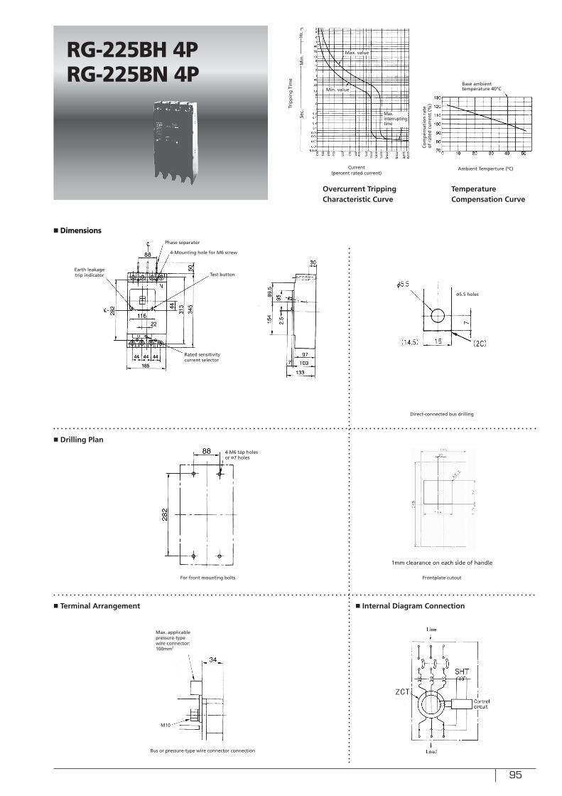
95
■ Dimensions■ Dimensions
■ Drilling Plan
■ Terminal Arrangement ■ Internal Diagram Connection
RG-225BH 4PRG-225BN 4P
Sec.
Min
.H
r.
Current (percent rated current)
Trip
pin
g T
ime
Overcurrent Tripping Characteristic Curve
For front mounting bolts
Direct-connected bus drilling
Frontplate cutout
Test button
4-Mounting hole for M6 screw
Rated sensitivity current selector
Earth leakage trip indicator
ø5.5 holes
4-M6 tap holes or ø7 holes
Phase separator
Max. applicable pressure-typewire connector: 100mm2
Max. interrupting time
Min. value
Max. value
Temperature Compensation Curve
Co
mp
ensa
tio
n r
ate
of
rate
d c
urr
ent
(%)
Ambient Temperture (ºC)
Base ambient temperature 40ºC
1mm clearance on each side of handle
Bus or pressure-type wire connector connection
M10
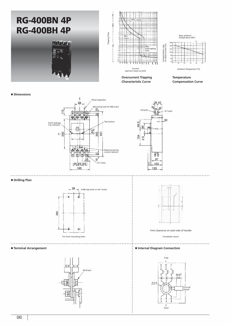
96
■ Dimensions
■ Drilling Plan
■ Terminal Arrangement ■ Internal Diagram Connection
RG-400BN 4PRG-400BH 4P
Sec.
Min
.H
r.
Ambient Temperture (ºC)Current (percent rated current)
Co
mp
ensa
tio
n r
ate
of
rate
d c
urr
ent
(%)Tr
ipp
ing
Tim
e
Overcurrent Tripping Characteristic Curve
Temperature Compensation Curve
Base ambient temperature 40ºC
For front mounting bolts Frontplate cutout
1mm clearance on each side of handle
Min. value
Max. value
4-M6 tap holes or ø4-7 holes
M10 bolt
Max. interrupting time
Test button
Rated sensitivity current selector
Phase separator
S.N pole
Mounting hole for M6 screw
Earth leakage trip indicator
ø11 holes
R.T pole
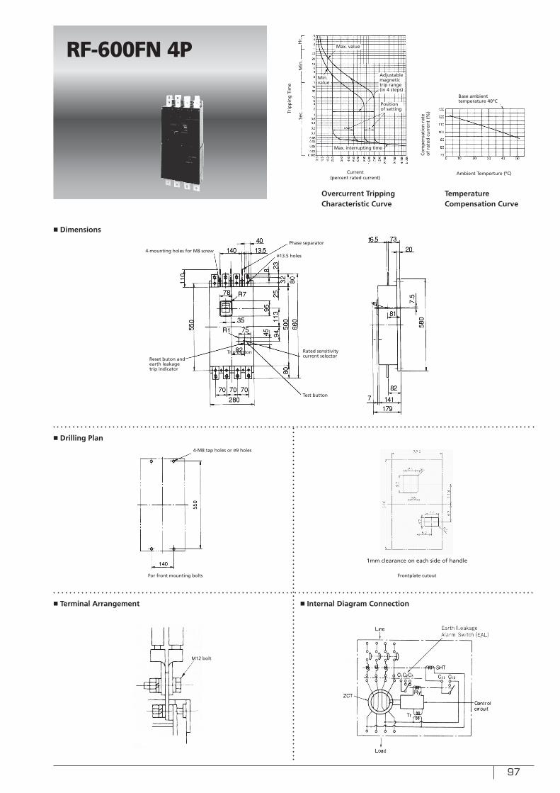
97
■ Dimensions
■ Drilling Plan
■ Terminal Arrangement ■ Internal Diagram Connection
RF-600FN 4P
Sec.
Min
.H
r.
Ambient Temperture (ºC)Current (percent rated current)
Co
mp
ensa
tio
n r
ate
of
rate
d c
urr
ent
(%)Tr
ipp
ing
Tim
e
Overcurrent Tripping Characteristic Curve
Temperature Compensation Curve
Base ambient temperature 40ºC
For front mounting bolts Frontplate cutout
1mm clearance on each side of handle
Min. value
Max. value
4-M8 tap holes or ø9 holes
M12 bolt
Max. interrupting time
Test button
Rated sensitivity current selector
Phase separator
Trip button
4-mounting holes for M8 screw
Reset buton and earth leakage trip indicator
ø13.5 holes
Adjustable magnetic trip range (in 4 steps)
Position of setting
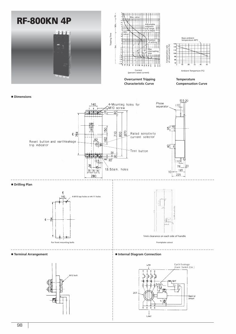
98
■ Drilling Plan
■ Terminal Arrangement ■ Internal Diagram Connection
RF-800KN 4P
Sec.
Min
.H
r.
Ambient Temperture (ºC)Current (percent rated current)
Co
mp
ensa
tio
n r
ate
of
rate
d c
urr
ent
(%)Trip
pin
g T
ime
Overcurrent Tripping Characteristic Curve
Temperature Compensation Curve
Base ambient temperature 40ºC
For front mounting bolts Frontplate cutout
1mm clearance on each side of handle
Min. value
Max. value
4-M10 tap holes or ø4-11 holes
M12 bolt
Max. interrupting time
Adjustable magnetic trip range (in 4 steps)
Position of setting
■ Dimensions
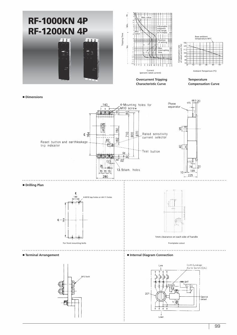
99
■ Drilling Plan
■ Terminal Arrangement ■ Internal Diagram Connection
RF-1000KN 4PRF-1200KN 4P
Frontplate cutout
1mm clearance on each side of handle
■ Dimensions
Sec.
Min
.H
r.
Ambient Temperture (ºC)Current (percent rated current)
Co
mp
ensa
tio
n r
ate
of
rate
d c
urr
ent
(%)Trip
pin
g T
ime
Overcurrent Tripping Characteristic Curve
Temperature Compensation Curve
Base ambient temperature 40ºC
Min. value
Max. value
Max. interrupting time
Adjustable magnetic trip range (in 4 steps)
Position of setting
For front mounting bolts
4-M10 tap holes or ø4-11 holes
M12 bolt
68.5t15
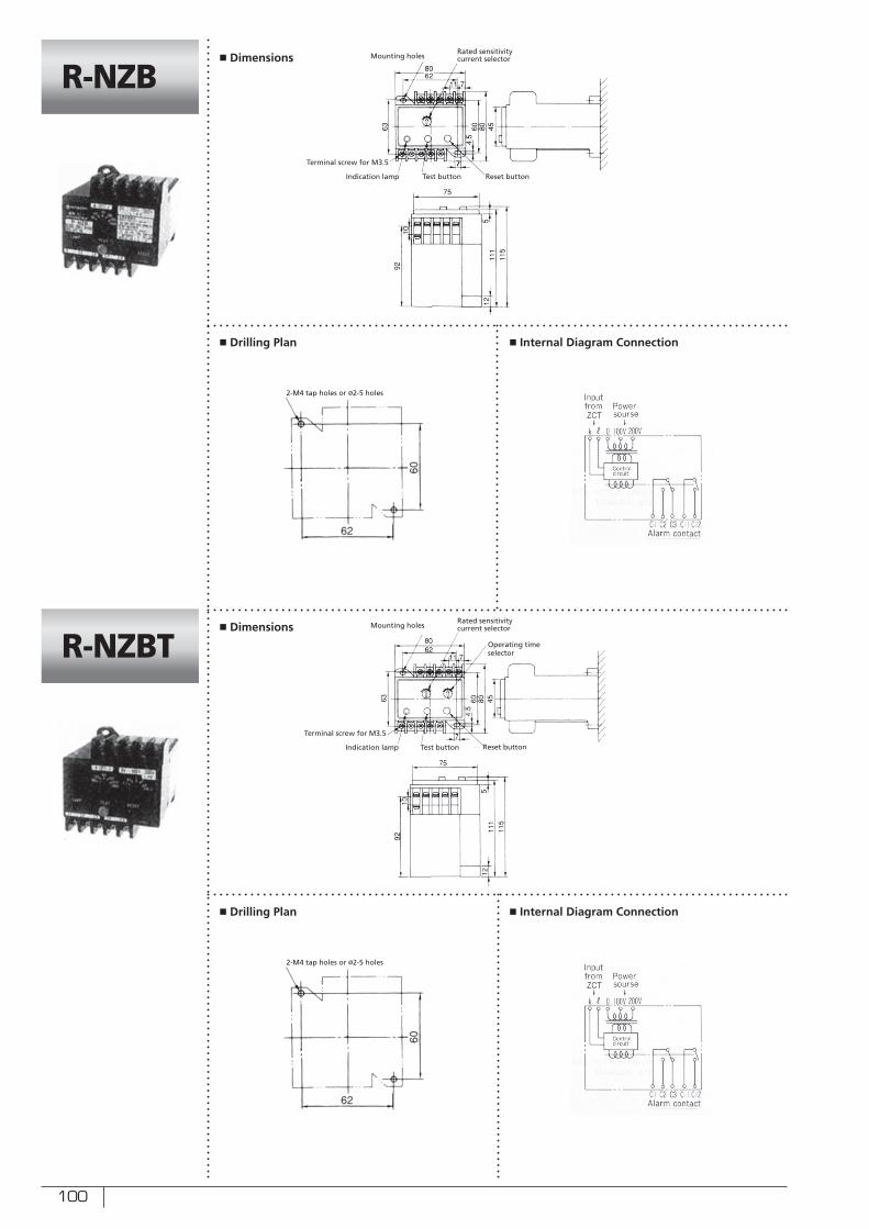
100
■ Drilling Plan
■ Drilling Plan
■ Internal Diagram Connection
■ Internal Diagram Connection
R-NZB
R-NZBT
■ Dimensions
■ Dimensions
Test button
Test button
Rated sensitivity current selector
Rated sensitivity current selector
Reset button
Reset button
Mounting holes
Mounting holes
Terminal screw for M3.5
Terminal screw for M3.5
Indication lamp
Indication lamp
2-M4 tap holes or ø2-5 holes
2-M4 tap holes or ø2-5 holes
Operating time selector
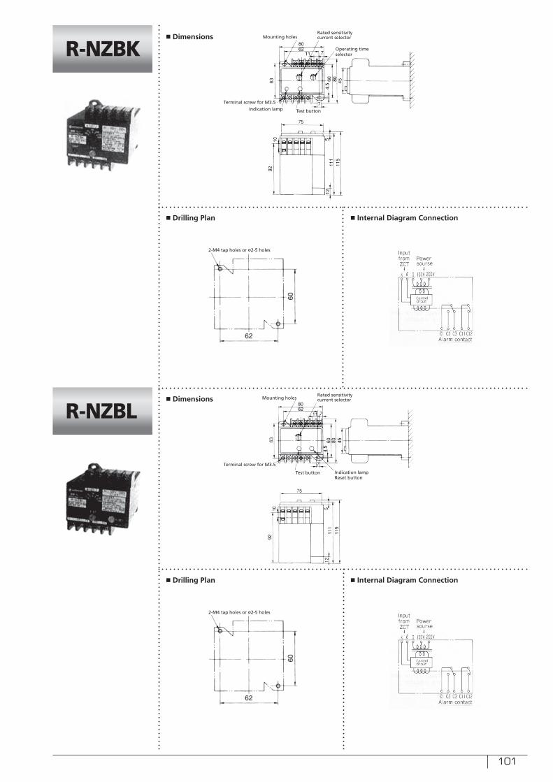
101
■ Drilling Plan
■ Drilling Plan
■ Internal Diagram Connection
■ Internal Diagram Connection
R-NZBK
R-NZBL
■ Dimensions
■ Dimensions
Test button
Test button
Rated sensitivity current selector
Rated sensitivity current selector
Mounting holes
Mounting holes
Terminal screw for M3.5
Terminal screw for M3.5
Indication lamp
Indication lampReset button
2-M4 tap holes or ø2-5 holes
2-M4 tap holes or ø2-5 holes
Operating time selector
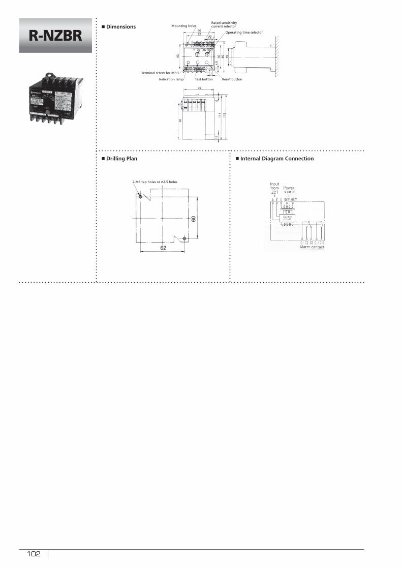
102
■ Drilling Plan ■ Internal Diagram Connection
R-NZBR■ Dimensions
Reset button
Rated sensitivity current selector Mounting holes
Terminal screw for M3.5
Indication lamp
2-M4 tap holes or ø2-5 holes
Test button
Operating time selector
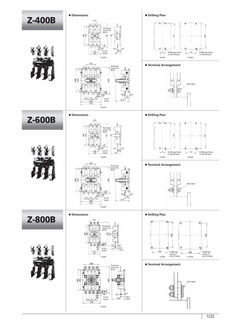
103
■ Drilling Plan
■ Drilling Plan
■ Drilling Plan
■ Terminal Arrangement
■ Terminal Arrangement
■ Terminal Arrangement
Z-400B
Z-600B
Z-800B
Terminal screw for M3.5
Terminal screw for M3.5
Terminal screw for M3.5
ø13.5 holes
ø13.5 holes
ø13.5 holes
M12 bolt
M12 bolt
M12 bolt
■ Dimensions
■ Dimensions
■ Dimensions
3 pole
3 pole
3 pole
4 pole
4 pole
4 pole
4 pole
4 pole
4 pole
3 pole
3 pole
3 pole
Terminal screw for M3.5
Terminal screw for M3.5
Terminal screw for M3.5
ø13.5 holes
ø13.5 holes
ø13.5 holes
4-M6 tap holes or ø4-8 holes
4-M6 tap holes or ø4-8 holes
4-M8 tap holes or ø4-10 holes
4-M8 tap holes or ø4-10 holes
4-M6 tap holes or ø4-8 holes
4-M6 tap holes or ø4-8 holes
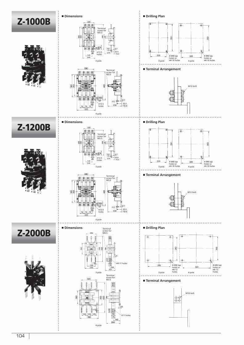
104
■ Drilling Plan
■ Drilling Plan
■ Drilling Plan
■ Terminal Arrangement
■ Terminal Arrangement
■ Terminal Arrangement
Z-1000B
Z-1200B
Z-2000BTerminal screw for M3.5
Terminal screw for M3.5
Terminal screw for M3.5
ø4-11 holes
ø13.5 holes
ø13.5 holes
M10 bolt
M12 bolt
M12 bolt
■ Dimensions
■ Dimensions
■ Dimensions
3 pole
3 pole
3 pole
4 pole
4 pole
4 pole
4 pole
4 pole
4 pole
3 pole
3 pole
3 pole
Terminal screw for M3.5
Terminal screw for M3.5
Terminal screw for M3.5
ø11 holes
ø13.5 holes
ø13.5 holes
4-M8 tap holes or ø4-12 holes
4-M8 tap holes or ø4-12 holes
4-M8 tap holes or ø4-10 holes
4-M8 tap holes or ø4-10 holes
4-M8 tap holes or ø4-10 holes
4-M8 tap holes or ø4-10 holes
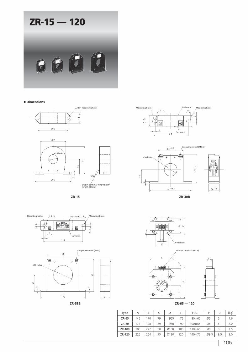
105
ZR-15 — 120
■ Dimensions
Type A B C D E F×G H J (kg)
ZR-65 145 170 79 Ø65 75 80×60 Ø6 6 1.6
ZR-80 172 198 89 Ø80 90 100×65 Ø6 6 2.0
ZR-100 185 222 90 Ø100 100 110×65 Ø8 8 2.5
ZR-120 226 264 95 Ø120 120 140×70 Ø9.5 9.5 3.0
ZR-15 ZR-30B
ZR-58B ZR-65 — 120
2-M4 mounting holes Mounting holes
Mounting holes
Mounting holes
Mounting holes
ø15 holes
ø30 holes
ø58 holes
4-øH holes
Outlet terminal wire 0.5mm2
length 500mm
Surface K
Surface K
Surface L
Surface L
Output terminal (M3.5)
Output terminal (M3.5) Output terminal (M3.5)
øD hol
es
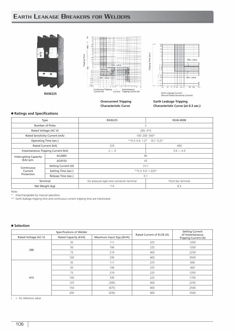
106
■ Ratings and Specifi cations
■ Selection
Sec.
Min
.H
r.
Earth Leakage Current(Percent Rated Sensitivity Current)
Current
Trip
pin
g T
ime
Trip
pin
g T
ime
(sec
.)
Overcurrent Tripping Characteristic Curve
Earth Leakage Tripping Characteristic Curve (at 0.3 sec.)
Min. value
Max. value
Setting time (sec.)
RXW225
EARTH LEAKAGE BREAKERS FOR WELDERS
Continuous Tripping Current (A)
Instantaneous Tripping Current (A)
Min. value
Max. value
Type RXW225 RGW-400B
Number of Poles 2
Rated Voltage (AC V) 200, 415
Rated Sensitivity Current (mA) 100∙200 ∙500*
Operating Time (sec.) **0.3 ∙0.6 ∙1.2* (0.1 ∙0.2)*
Rated Current (kA) 225 400
Instantaneous Tripping Current (kA) 3 — 4 3.6 — 4.4
Interrupting Capacity (kA) sym.
AC200V 85
AC415V 42
ContinuousCurrent
Protection
Setting Current (A) 3±1
Setting Time (sec.) **0.3 ∙0.6 ∙1.2(3)*
Release Time (sec.) 0.1
Terminal For pressure-type wire connector terminal Front bar terminal
Net Weight (kg) 7.4 8.3
Note:* Interchangeable by manual operation.** Earth leakage tripping time and continuous current tripping time are interlocked.
( ): for reference value
Specifi cations of WelderRated Current of ELCB (A)
Setting Current of Instantaneous
Tripping Current (A)Rated Voltage (AC V) Rated Capacity (kVA) Maximum Input (typ.)(kVA)
200
35 111 225 1200
50 106 225 1200
75 219 400 2250
100 330 400 3500
415
35 111 225 600
50 106 225 600
75 219 225 1200
100 330 225 1700
125 (395) 400 2250
150 (475) 400 2500
200 (630) 400 3500
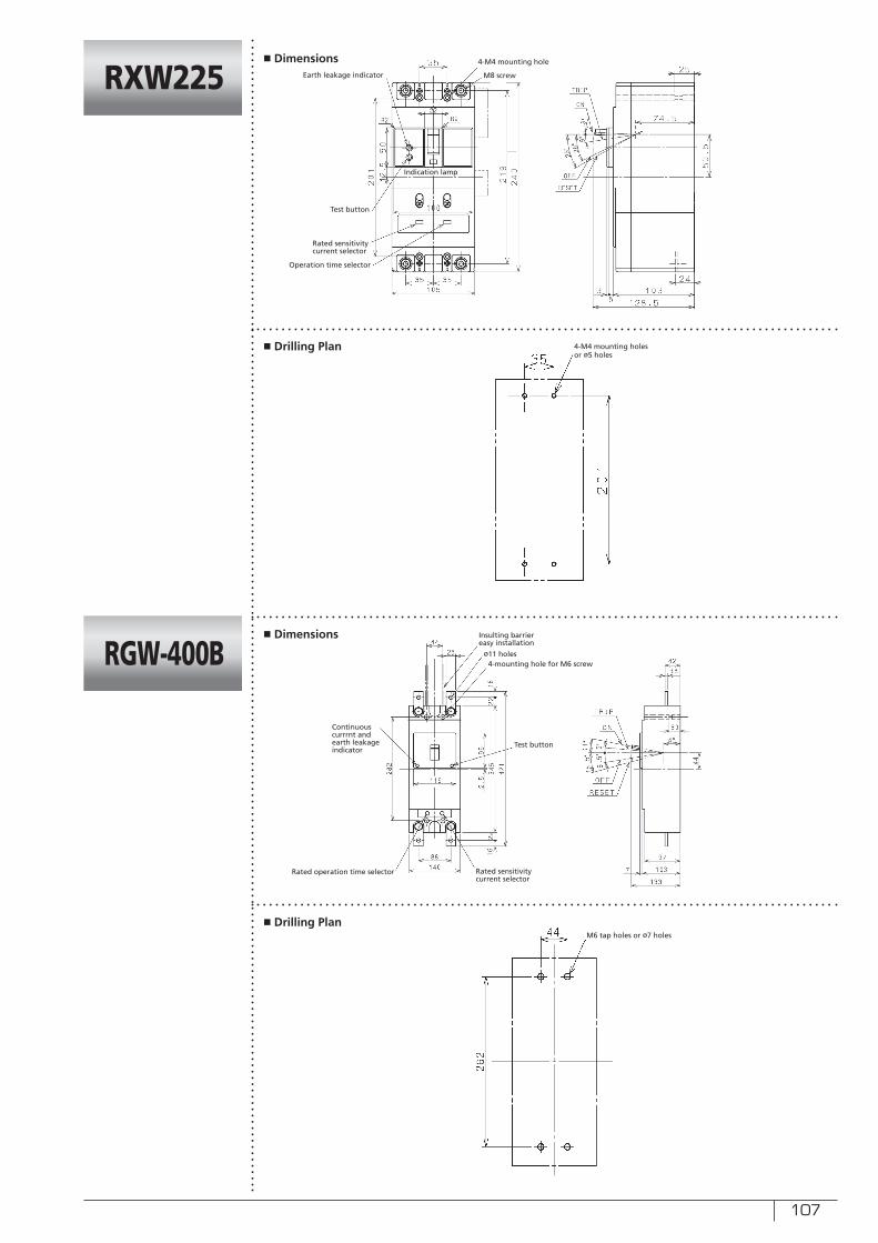
107
■ Drilling Plan
■ Drilling Plan
RXW225
RGW-400B
■ Dimensions
■ Dimensions
Test button
Test button
Rated sensitivity current selector
Rated sensitivity current selector
4-M4 mounting hole
4-mounting hole for M6 screw
Operation time selector
Rated operation time selector
Indication lamp
M6 tap holes or ø7 holes
M8 screwEarth leakage indicator
Insulting barrier easy installation
Continuous currrnt and earth leakageindicator
ø11 holes
4-M4 mounting holes or ø5 holes
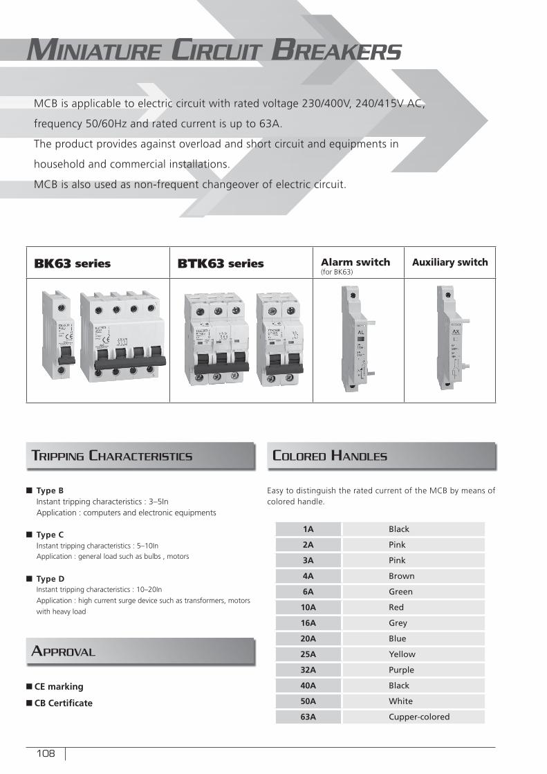
108
TRIPPING CHARACTERISTICS
BK63 series BTK63 series Alarm switch (for BK63)
Auxiliary switch
MINIATURE CIRCUIT BREAKERS
MCB is applicable to electric circuit with rated voltage 230/400V, 240/415V AC,
frequency 50/60Hz and rated current is up to 63A.
The product provides against overload and short circuit and equipments in
household and commercial installations.
MCB is also used as non-frequent changeover of electric circuit.
COLORED HANDLES
APPROVAL
Easy to distinguish the rated current of the MCB by means of colored handle.
1A Black
2A Pink
3A Pink
4A Brown
6A Green
10A Red
16A Grey
20A Blue
25A Yellow
32A Purple
40A Black
50A White
63A Cupper-colored
n Type B Instant tripping characteristics : 3–5InApplication : computers and electronic equipments
n Type CInstant tripping characteristics : 5–10InApplication : general load such as bulbs , motors
n Type DInstant tripping characteristics : 10–20In
Application : high current surge device such as transformers, motors
with heavy load
n CE marking
n CB Certifi cate
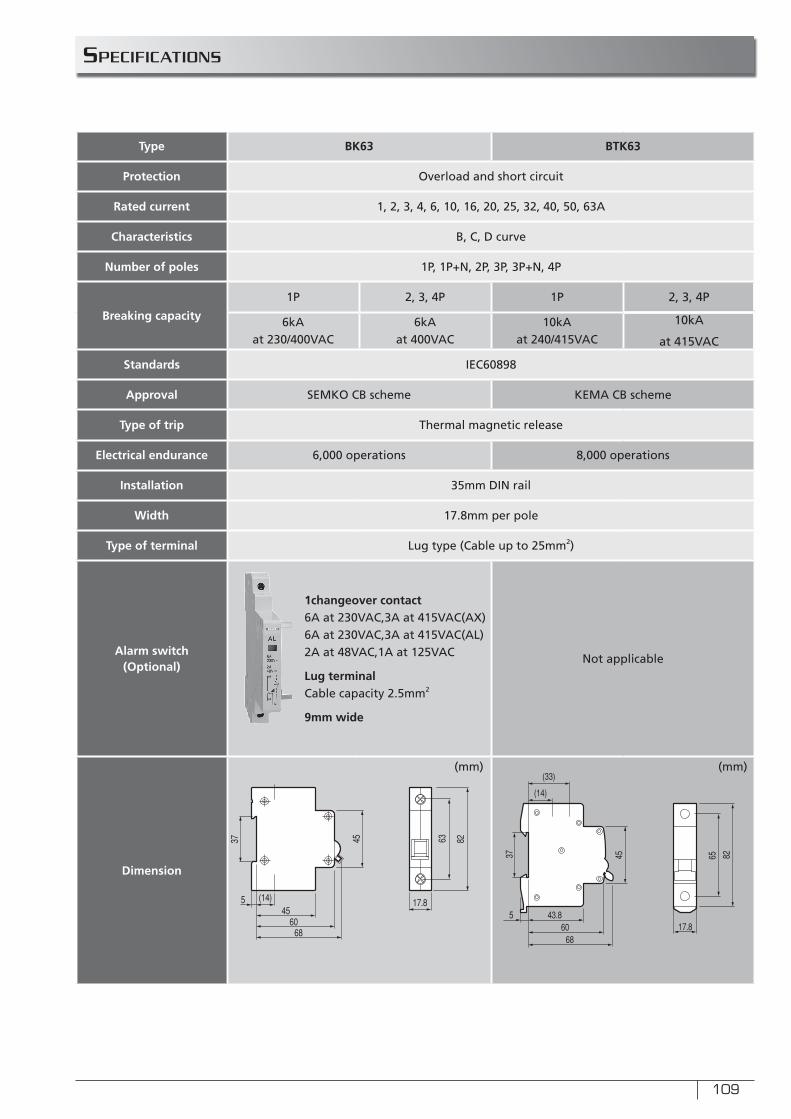
109
SPECIFICATIONS
Type BK63 BTK63
Protection Overload and short circuit
Rated current 1, 2, 3, 4, 6, 10, 16, 20, 25, 32, 40, 50, 63A
Characteristics B, C, D curve
Number of poles 1P, 1P+N, 2P, 3P, 3P+N, 4P
Breaking capacity
1P 2, 3, 4P 1P 2, 3, 4P
6kA at 230/400VAC
6kAat 400VAC
10kAat 240/415VAC
10kA
at 415VAC
Standards IEC60898
Approval SEMKO CB scheme KEMA CB scheme
Type of trip Thermal magnetic release
Electrical endurance 6,000 operations 8,000 operations
Installation 35mm DIN rail
Width 17.8mm per pole
Type of terminal Lug type (Cable up to 25mm2)
Alarm switch(Optional)
1changeover contact6A at 230VAC,3A at 415VAC(AX)6A at 230VAC,3A at 415VAC(AL)2A at 48VAC,1A at 125VAC
Lug terminalCable capacity 2.5mm2
9mm wide
Not applicable
Dimension
(mm) (mm)
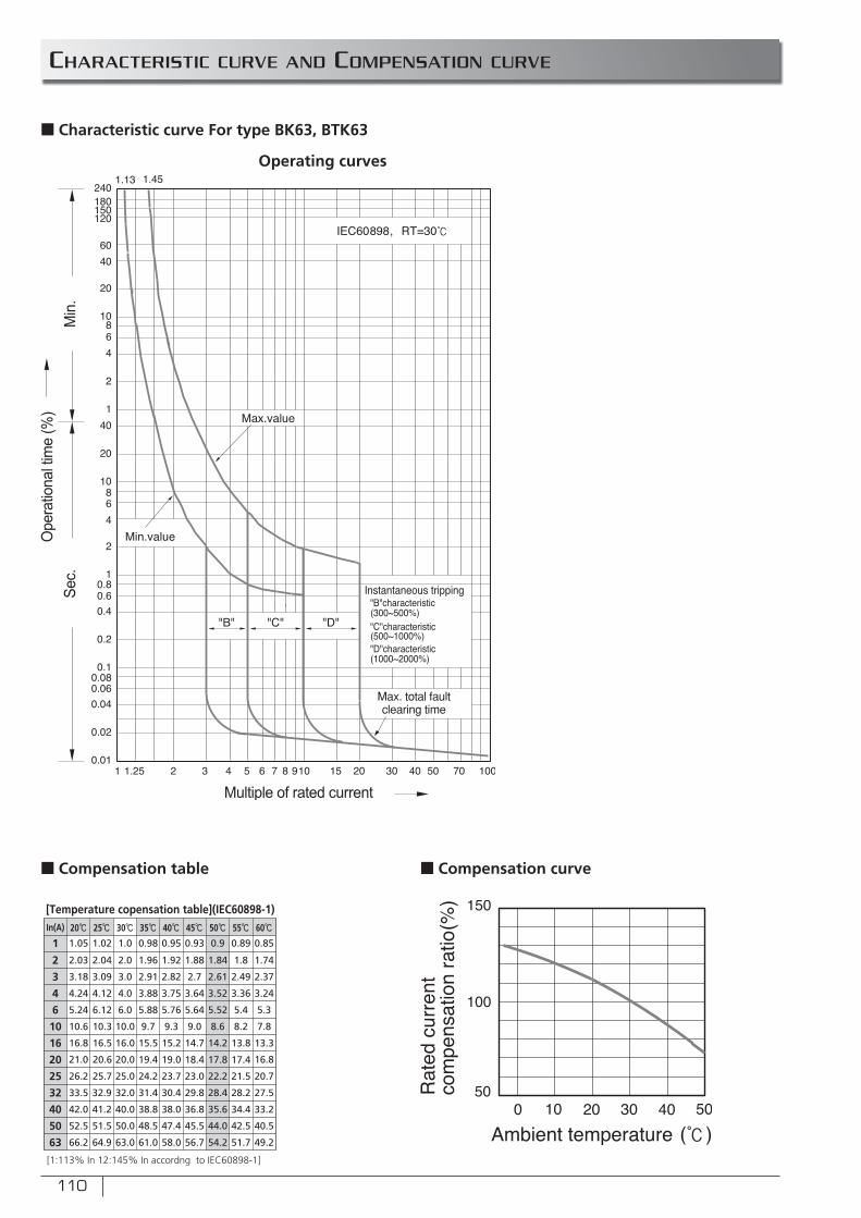
110
CHARACTERISTIC CURVE AND COMPENSATION CURVE
n Characteristic curve For type BK63, BTK63
Operating curves
In(A)
1
2
3
4
6
10
16
25
32
40
50
63
1.05
2.03
3.18
4.24
5.24
10.6
16.8
26.2
33.5
42.0
52.5
66.2
1.02
2.04
3.09
4.12
6.12
10.3
16.5
25.7
32.9
41.2
51.5
64.9
1.0
2.0
3.0
4.0
6.0
10.0
16.0
25.0
32.0
40.0
50.0
63.0
0.98
1.96
2.91
3.88
5.88
9.7
15.5
24.2
31.4
38.8
48.5
61.0
0.95
1.92
2.82
3.75
5.76
9.3
15.2
23.7
30.4
38.0
47.4
58.0
0.93
1.88
2.7
3.64
5.64
9.0
14.7
23.0
29.8
36.8
45.5
56.7
0.9
1.84
2.61
3.52
5.52
8.6
14.2
22.2
28.4
35.6
44.0
54.2
0.89
1.8
2.49
3.36
5.4
8.2
13.8
21.5
28.2
34.4
42.5
51.7
0.85
1.74
2.37
3.24
5.3
7.8
13.3
20 21.0 20.6 20.0 19.4 19.0 18.4 17.8 17.4 16.8
20.7
27.5
33.2
40.5
49.2
[Temperature copensation table](IEC60898-1)
[1:113% In 12:145% In accordng to IEC60898-1]
n Compensation table n Compensation curve

111
n RCCBs with rated sensitivity up to 30mA can be used as supplementary protecting device in case other protecting device fails its protection against electric shock.
n RCCBs designed for household installation and other similar application, is for non-professional operation, and no maintenance is required.
n RCCBs provides no protection against electric shock resulted from direct contacts of both protected lines, or leakage current between these two lines.
n Particular devices such as surge protective devices, surge arresters etc are recommended to installation at upstream line to RCCBs as precaution against potential surge voltage and current occurring at its power input side.
n Satisfying conditions and applications as mentioned above, RCCBs with ON-OFF indicating device is considered suitable for isolation function.
FEATURES
RK63 series
RESIDUAL CURRENT CIRCUIT BREAKERS
RCCB is applicable to electric circuits with rated voltage 240/415VAC, frequency 50/60Hz
and rated current up to63A. The RCCBs provides indirect protection to the operator’s body
under such condition that the exposed live parts should be connected to a proper earthing
pole. The RCCB also provides protection against the fi re danger caused by earth fault
current due to function failure of over current protection device.
COLORED HANDLES
APPROVAL
n CE marking
n CB Certifi cate
n Black only.
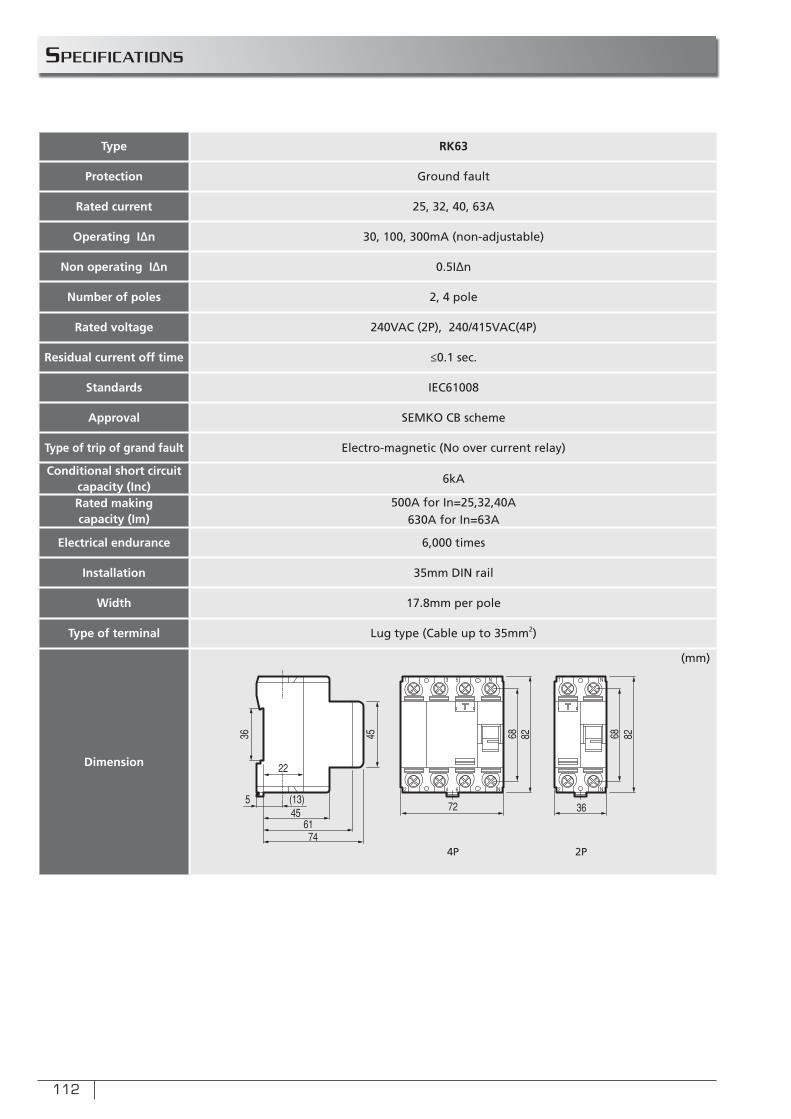
112
SPECIFICATIONS
Type RK63
Protection Ground fault
Rated current 25, 32, 40, 63A
Operating I∆n 30, 100, 300mA (non-adjustable)
Non operating I∆n 0.5I∆n
Number of poles 2, 4 pole
Rated voltage 240VAC (2P), 240/415VAC(4P)
Residual current off time ≤0.1 sec.
Standards IEC61008
Approval SEMKO CB scheme
Type of trip of grand fault Electro-magnetic (No over current relay)
Conditional short circuitcapacity (Inc)
6kA
Rated makingcapacity (Im)
500A for In=25,32,40A630A for In=63A
Electrical endurance 6,000 times
Installation 35mm DIN rail
Width 17.8mm per pole
Type of terminal Lug type (Cable up to 35mm2)
Dimension
(mm)
4P 2P
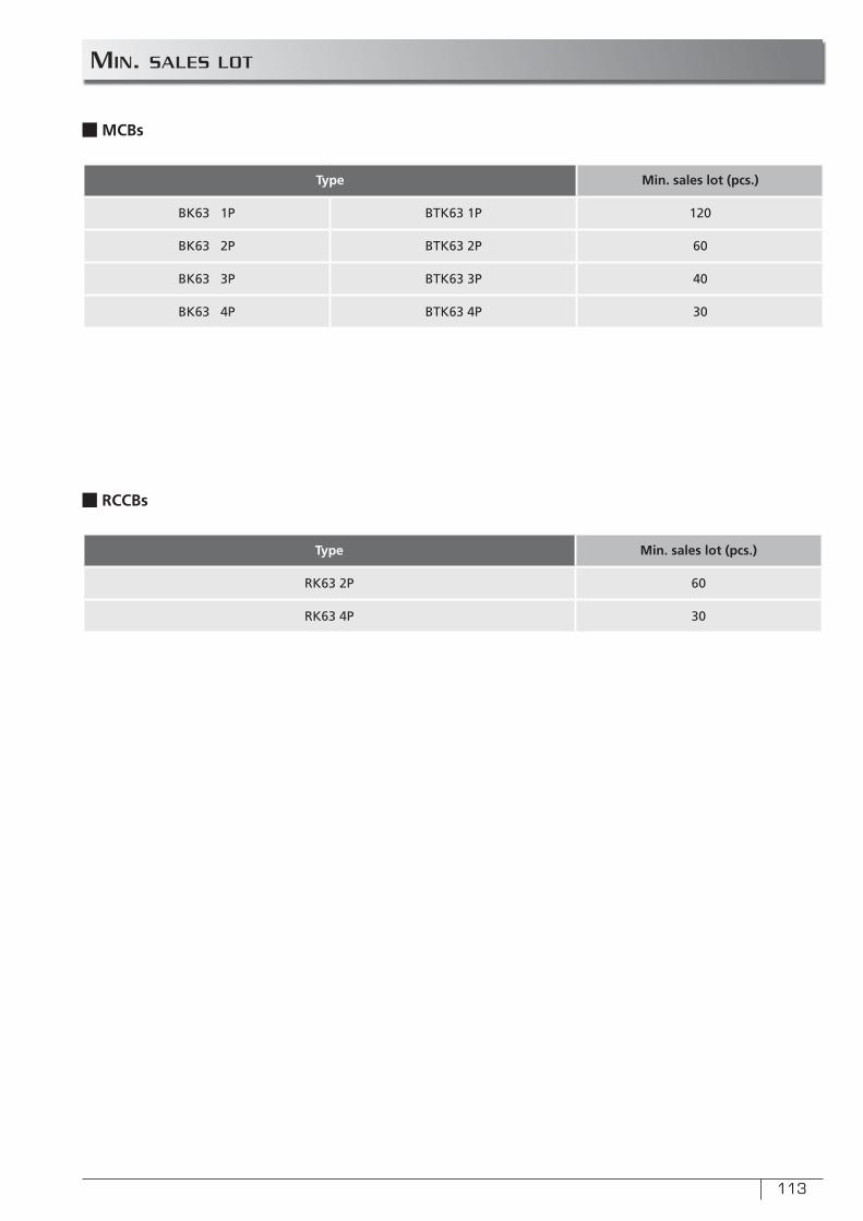
113
min. sALes LoT
Type Min. sales lot (pcs.)
BK63 1P BTK63 1P 120
BK63 2P BTK63 2P 60
BK63 3P BTK63 3P 40
BK63 4P BTK63 4P 30
nMCBs
Type Min. sales lot (pcs.)
RK63 2P 60
RK63 4P 30
n RCCBs
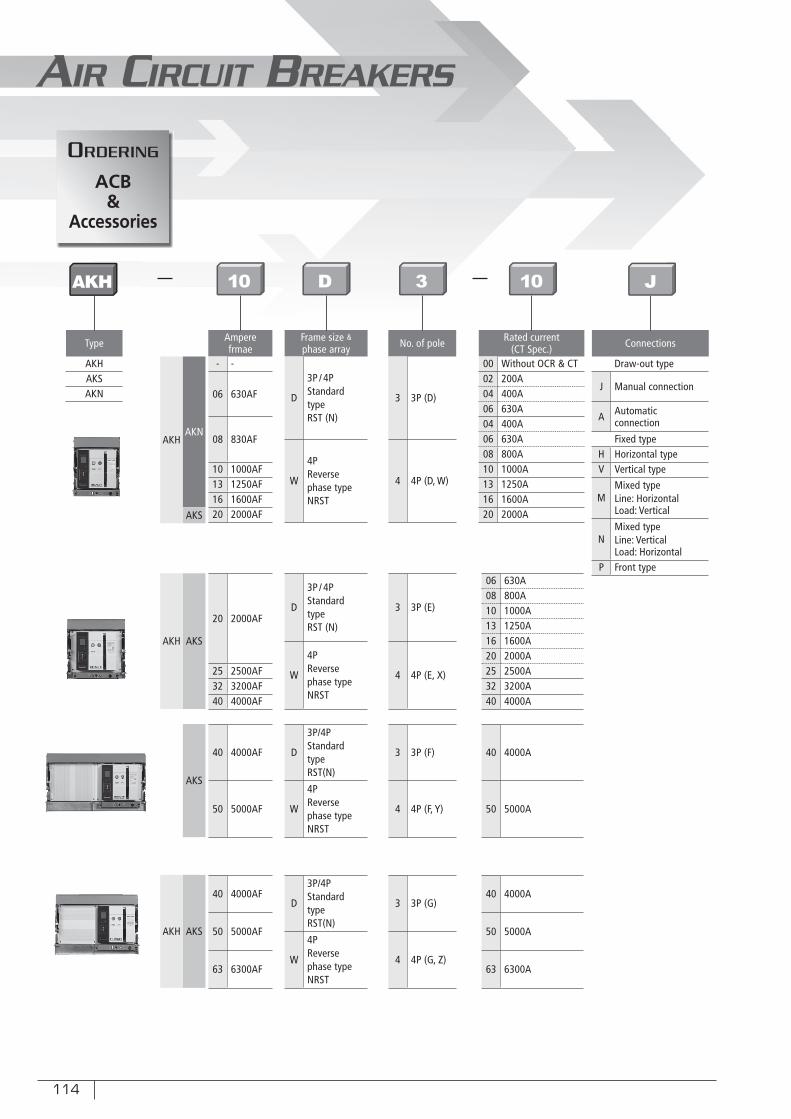
114
AIR CIRCUIT BREAKERS
Type
AKHAKSAKN
No. of pole
3 3P (D)
4 4P (D, W)
3 3P (E)
4 4P (E, X)
3 3P (F)
4 4P (F, Y)
3 3P (G)
4 4P (G, Z)
Frame size &phase array
D
3P / 4PStandardtypeRST (N)
W
4PReversephase typeNRST
D
3P / 4PStandardtypeRST (N)
W
4PReversephase typeNRST
D
3P/4PStandardtypeRST(N)
W
4PReversephase typeNRST
D
3P/4PStandardtypeRST(N)
W
4PReversephase typeNRST
Rated current(CT Spec.)
00 Without OCR & CT02 200A04 400A06 630A04 400A06 630A08 800A10 1000A13 1250A16 1600A20 2000A
06 630A08 800A10 1000A13 1250A16 1600A20 2000A25 2500A32 3200A40 4000A
40 4000A
50 5000A
40 4000A
50 5000A
63 6300A
Connections
Draw-out type
J Manual connection
A Automaticconnection
Fixed typeH Horizontal typeV Vertical type
MMixed typeLine: HorizontalLoad: Vertical
NMixed typeLine: VerticalLoad: Horizontal
P Front type
Amperefrmae
- -
06 630AF
08 830AF
10 1000AF13 1250AF16 1600AF20 2000AF
20 2000AF
25 2500AF32 3200AF40 4000AF
40 4000AF
50 5000AF
40 4000AF
50 5000AF
63 6300AF
AKHAKN
AKS
AKH AKS
AKH AKS
AKS
AKH
oRDeRinG
ACB&
Accessories
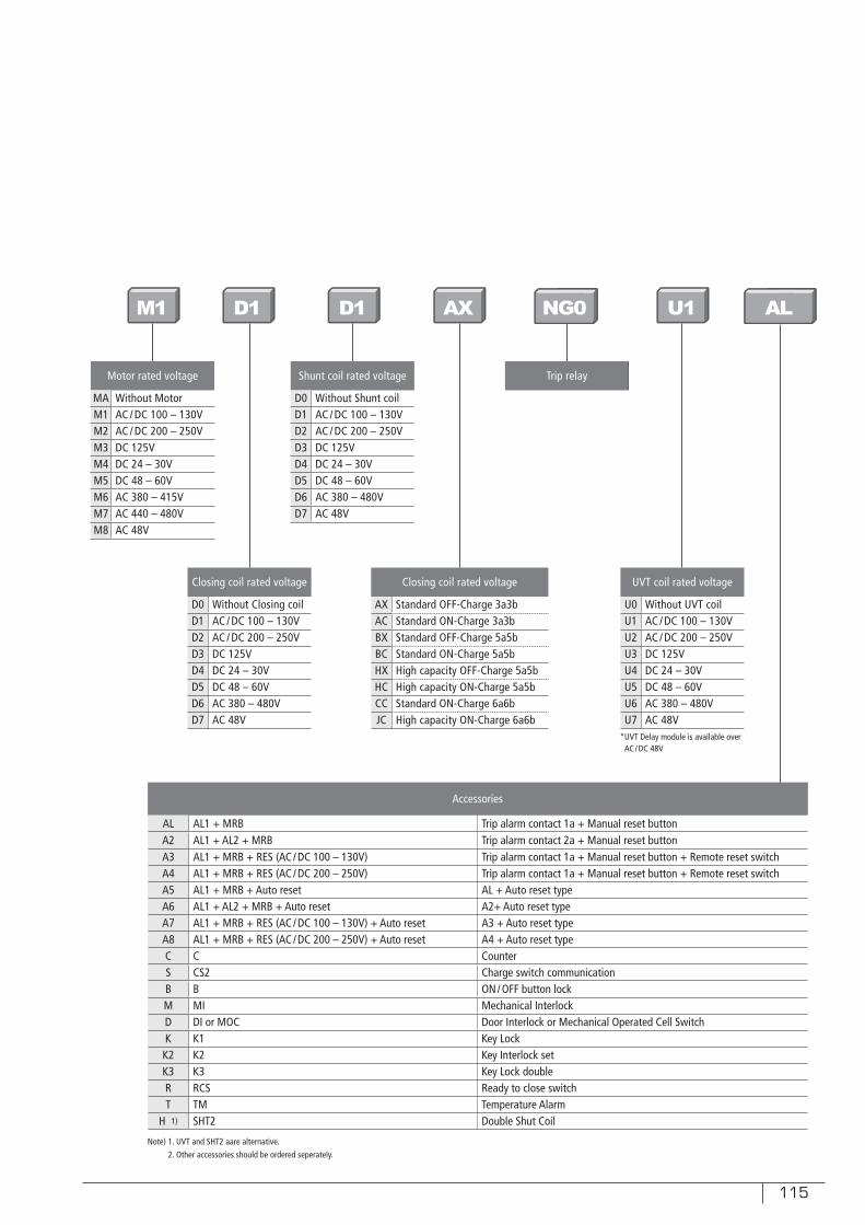
115
Motor rated voltage
MA Without MotorM1 AC / DC 100 – 130VM2 AC / DC 200 – 250VM3 DC 125VM4 DC 24 – 30VM5 DC 48 – 60VM6 AC 380 – 415VM7 AC 440 – 480VM8 AC 48V
Shunt coil rated voltage
D0 Without Shunt coilD1 AC / DC 100 – 130VD2 AC / DC 200 – 250VD3 DC 125VD4 DC 24 – 30VD5 DC 48 – 60VD6 AC 380 – 480VD7 AC 48V
Closing coil rated voltage
D0 Without Closing coilD1 AC / DC 100 – 130VD2 AC / DC 200 – 250VD3 DC 125VD4 DC 24 – 30VD5 DC 48 – 60VD6 AC 380 – 480VD7 AC 48V
UVT coil rated voltage
U0 Without UVT coilU1 AC / DC 100 – 130VU2 AC / DC 200 – 250VU3 DC 125VU4 DC 24 – 30VU5 DC 48 – 60VU6 AC 380 – 480VU7 AC 48V
Closing coil rated voltage
AX Standard OFF-Charge 3a3bAC Standard ON-Charge 3a3bBX Standard OFF-Charge 5a5bBC Standard ON-Charge 5a5bHX High capacity OFF-Charge 5a5bHC High capacity ON-Charge 5a5bCC Standard ON-Charge 6a6bJC High capacity ON-Charge 6a6b
Trip relay
*UVT Delay module is available over AC / DC 48V
Accessories
AL AL1 + MRB Trip alarm contact 1a + Manual reset buttonA2 AL1 + AL2 + MRB Trip alarm contact 2a + Manual reset buttonA3 AL1 + MRB + RES (AC / DC 100 – 130V) Trip alarm contact 1a + Manual reset button + Remote reset switchA4 AL1 + MRB + RES (AC / DC 200 – 250V) Trip alarm contact 1a + Manual reset button + Remote reset switchA5 AL1 + MRB + Auto reset AL + Auto reset typeA6 AL1 + AL2 + MRB + Auto reset A2+ Auto reset typeA7 AL1 + MRB + RES (AC / DC 100 – 130V) + Auto reset A3 + Auto reset typeA8 AL1 + MRB + RES (AC / DC 200 – 250V) + Auto reset A4 + Auto reset typeC C CounterS CS2 Charge switch communicationB B ON / OFF button lockM MI Mechanical InterlockD DI or MOC Door Interlock or Mechanical Operated Cell SwitchK K1 Key Lock
K2 K2 Key Interlock setK3 K3 Key Lock doubleR RCS Ready to close switchT TM Temperature Alarm
H 1) SHT2 Double Shut Coil
Note) 1. UVT and SHT2 aare alternative.
2. Other accessories should be ordered seperately.
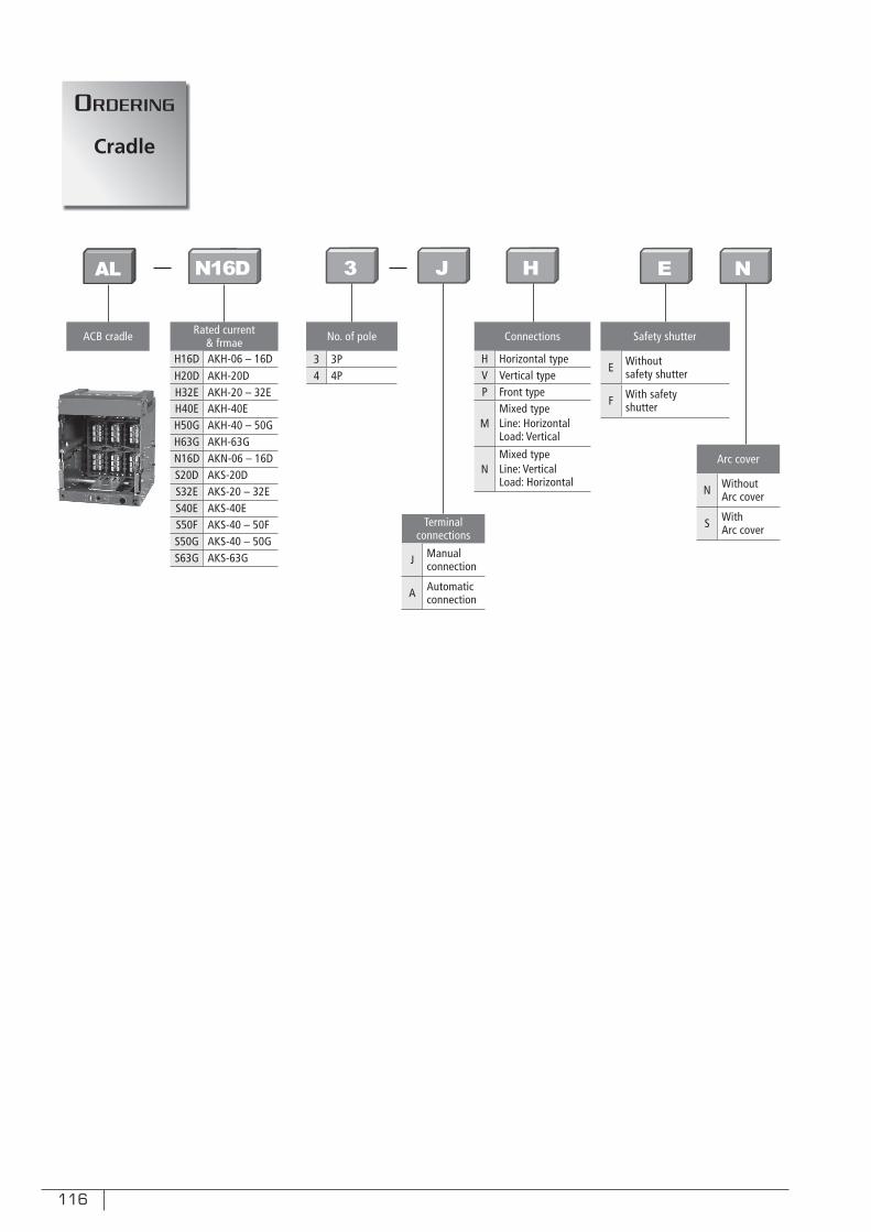
116
ACB cradle
Terminalconnections
J Manualconnection
A Automaticconnection
Arc cover
N WithoutArc cover
S WithArc cover
No. of pole
3 3P4 4P
Connections
H Horizontal typeV Vertical typeP Front type
MMixed typeLine: HorizontalLoad: Vertical
NMixed typeLine: VerticalLoad: Horizontal
Safety shutter
E Withoutsafety shutter
F With safetyshutter
Rated current & frmae
H16D AKH-06 – 16DH20D AKH-20DH32E AKH-20 – 32EH40E AKH-40EH50G AKH-40 – 50GH63G AKH-63GN16D AKN-06 – 16DS20D AKS-20DS32E AKS-20 – 32ES40E AKS-40ES50F AKS-40 – 50FS50G AKS-40 – 50GS63G AKS-63G
AL
oRDeRinG
Cradle
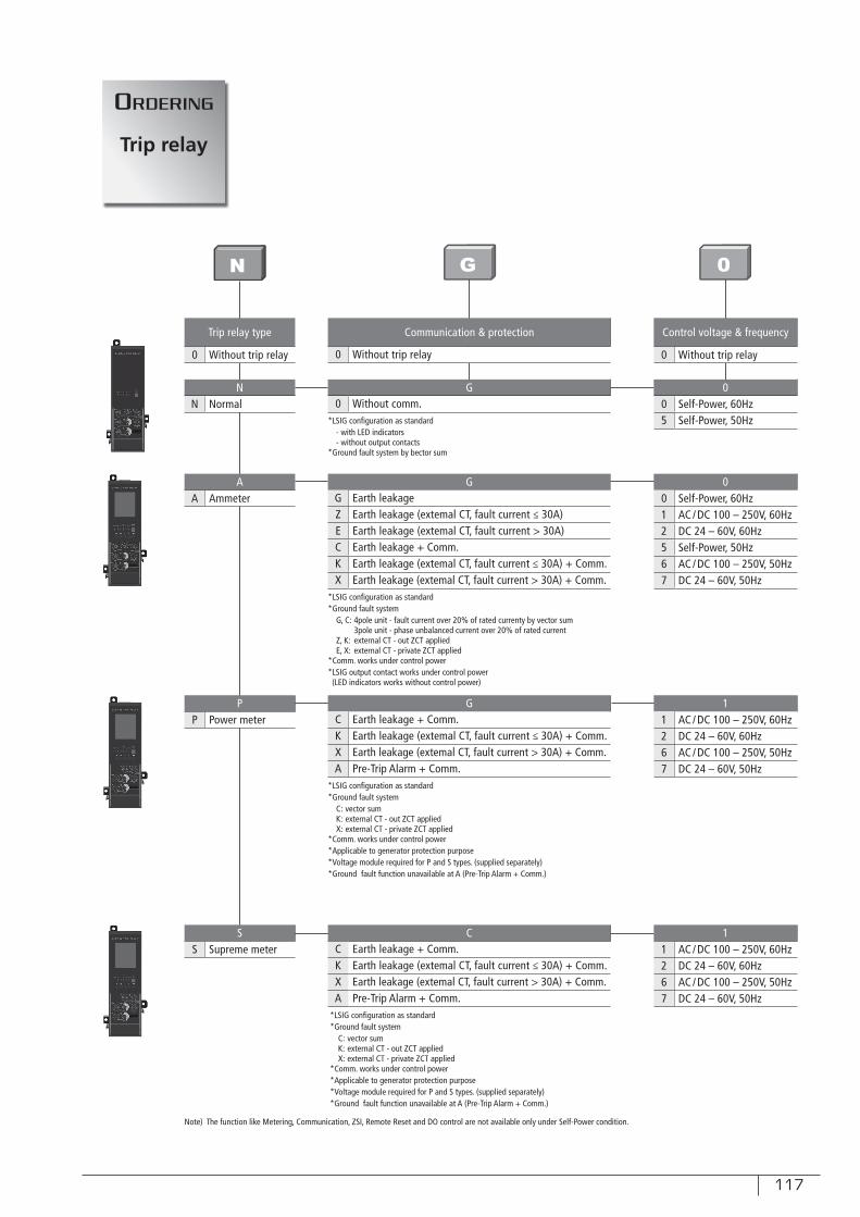
117
Trip relay type
0 Without trip relay
NN Normal
AA Ammeter
PP Power meter
SS Supreme meter
GG Earth leakageZ Earth leakage (extemal CT, fault current ≤ 30A)E Earth leakage (extemal CT, fault current > 30A)C Earth leakage + Comm.K Earth leakage (extemal CT, fault current ≤ 30A) + Comm.X Earth leakage (extemal CT, fault current > 30A) + Comm.
GC Earth leakage + Comm.K Earth leakage (extemal CT, fault current ≤ 30A) + Comm.X Earth leakage (extemal CT, fault current > 30A) + Comm.A Pre-Trip Alarm + Comm.
CC Earth leakage + Comm.K Earth leakage (extemal CT, fault current ≤ 30A) + Comm.X Earth leakage (extemal CT, fault current > 30A) + Comm.A Pre-Trip Alarm + Comm.
Communication & protection
0 Without trip relay
G0 Without comm.
Control voltage & frequency
0 Without trip relay
00 Self-Power, 60Hz5 Self-Power, 50Hz
00 Self-Power, 60Hz1 AC / DC 100 – 250V, 60Hz2 DC 24 – 60V, 60Hz5 Self-Power, 50Hz6 AC / DC 100 – 250V, 50Hz7 DC 24 – 60V, 50Hz
11 AC / DC 100 – 250V, 60Hz2 DC 24 – 60V, 60Hz6 AC / DC 100 – 250V, 50Hz7 DC 24 – 60V, 50Hz
11 AC / DC 100 – 250V, 60Hz2 DC 24 – 60V, 60Hz6 AC / DC 100 – 250V, 50Hz7 DC 24 – 60V, 50Hz
*LSIG confi guration as standard- with LED indicators- without output contacts
*Ground fault system by bector sum
*LSIG confi guration as standard*Ground fault system
G, C: 4pole unit - fault current over 20% of rated currenty by vector sum 3pole unit - phase unbalanced current over 20% of rated currentZ, K: external CT - out ZCT appliedE, X: external CT - private ZCT applied
*Comm. works under control power*LSIG output contact works under control power(LED indicators works without control power)
*LSIG confi guration as standard*Ground fault system
C: vector sumK: external CT - out ZCT appliedX: external CT - private ZCT applied
*Comm. works under control power*Applicable to generator protection purpose*Voltage module required for P and S types. (supplied separately)*Ground fault function unavailable at A (Pre-Trip Alarm + Comm.)
Note) The function like Metering, Communication, ZSI, Remote Reset and DO control are not available only under Self-Power condition.
oRDeRinG
Trip relay
N
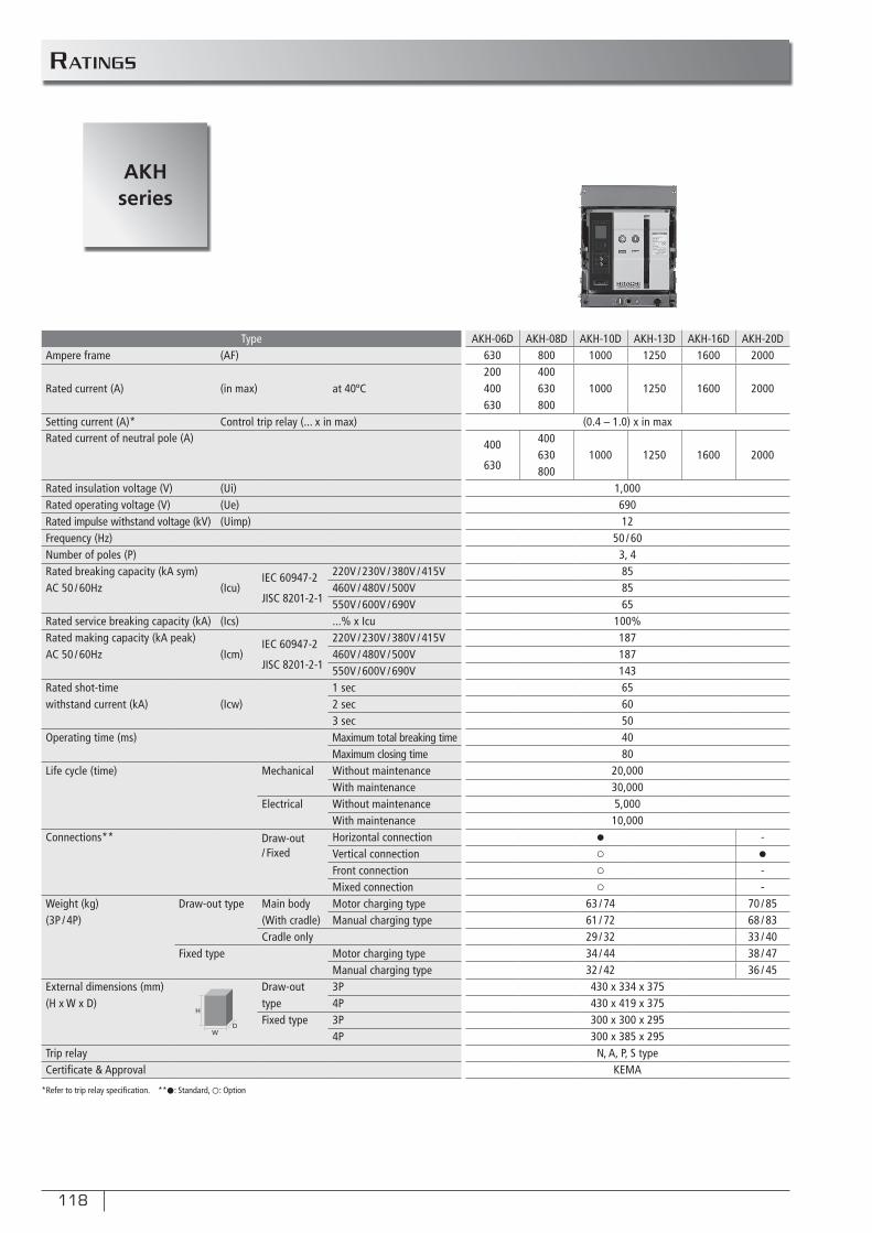
118
TypeAmpere frame (AF)
Rated current (A) (in max) at 40ºC
Setting current (A)* Control trip relay (... x in max)Rated current of neutral pole (A)
Rated insulation voltage (V) (Ui)Rated operating voltage (V) (Ue)Rated impulse withstand voltage (kV) (Uimp)Frequency (Hz)Number of poles (P)Rated breaking capacity (kA sym)
(Icu)IEC 60947-2
JISC 8201-2-1
220V / 230V / 380V / 415VAC 50 / 60Hz 460V / 480V / 500V
550V / 600V / 690VRated service breaking capacity (kA) (Ics) ...% x IcuRated making capacity (kA peak) IEC 60947-2
JISC 8201-2-1
220V / 230V / 380V / 415VAC 50 / 60Hz (Icm) 460V / 480V / 500V
550V / 600V / 690VRated shot-time 1 secwithstand current (kA) (Icw) 2 sec
3 secOperating time (ms) Maximum total breaking time
Maximum closing timeLife cycle (time) Mechanical Without maintenance
With maintenanceElectrical Without maintenance
With maintenanceConnections** Draw-out
/ FixedHorizontal connectionVertical connectionFront connectionMixed connection
Weight (kg) Draw-out type Main body Motor charging type(3P / 4P) (With cradle) Manual charging type
Cradle onlyFixed type Motor charging type
Manual charging typeExternal dimensions (mm) Draw-out 3P(H x W x D) type 4P
Fixed type 3P4P
Trip relayCertifi cate & Approval
AKH-06D AKH-08D AKH-10D AKH-13D AKH-16D AKH-20D630 800 1000 1250 1600 2000200 400400 630 1000 1250 1600 2000630 800
(0.4 – 1.0) x in max
400
630
400630 1000 1250 1600 2000800
1,00069012
50 / 603, 4858565
100%1871871436560504080
20,00030,0005,000
10,000● -○ ●
○ -○ -
63 / 74 70 / 8561 / 72 68 / 8329 / 32 33 / 4034 / 44 38 / 4732 / 42 36 / 45430 x 334 x 375430 x 419 x 375300 x 300 x 295300 x 385 x 295
N, A, P, S typeKEMA
*Refer to trip relay specifi cation. **●: Standard, ○: Option
RATinGs
AKHseries
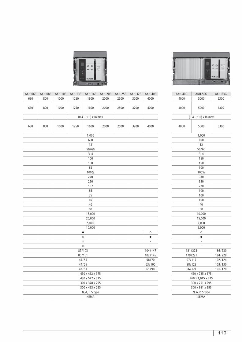
119
AKH-06E AKH-08E AKH-10E AKH-13E AKH-16E AKH-20E AKH-25E AKH-32E AKH-40E630 800 1000 1250 1600 2000 2500 3200 4000
630 800 1000 1250 1600 2000 2500 3200 4000
(0.4 – 1.0) x In max
630 800 1000 1250 1600 2000 2500 3200 4000
1,00069012
50 / 603, 410010085
100%2202201878575654080
15,00020,0005,000
10,000● ○
○ ●
○ -○ -
87 / 103 104 / 14785 / 101 102 / 14544 / 55 58 / 7044 / 55 63 / 10042 / 53 61 / 98430 x 412 x 375430 x 527 x 375300 x 378 x 295300 x 493 x 295
N, A, P, S typeKEMA
AKH-40G AKH-50G AKH-63G4000 5000 6300
4000 5000 6300
(0.4 – 1.0) x In max
4000 5000 6300
1,00069012
50 / 603, 4150150100
100%3303302201001001004080
10,00015,0002,0005,000
○
●
--
181 / 223 186 / 230179 / 221 184 / 22897 / 117 102 / 12498 / 123 103 / 13096 / 121 101 / 128
460 x 785 x 375460 x 1,015 x 375300 x 751 x 295300 x 981 x 295
N, A, P, S typeKEMA
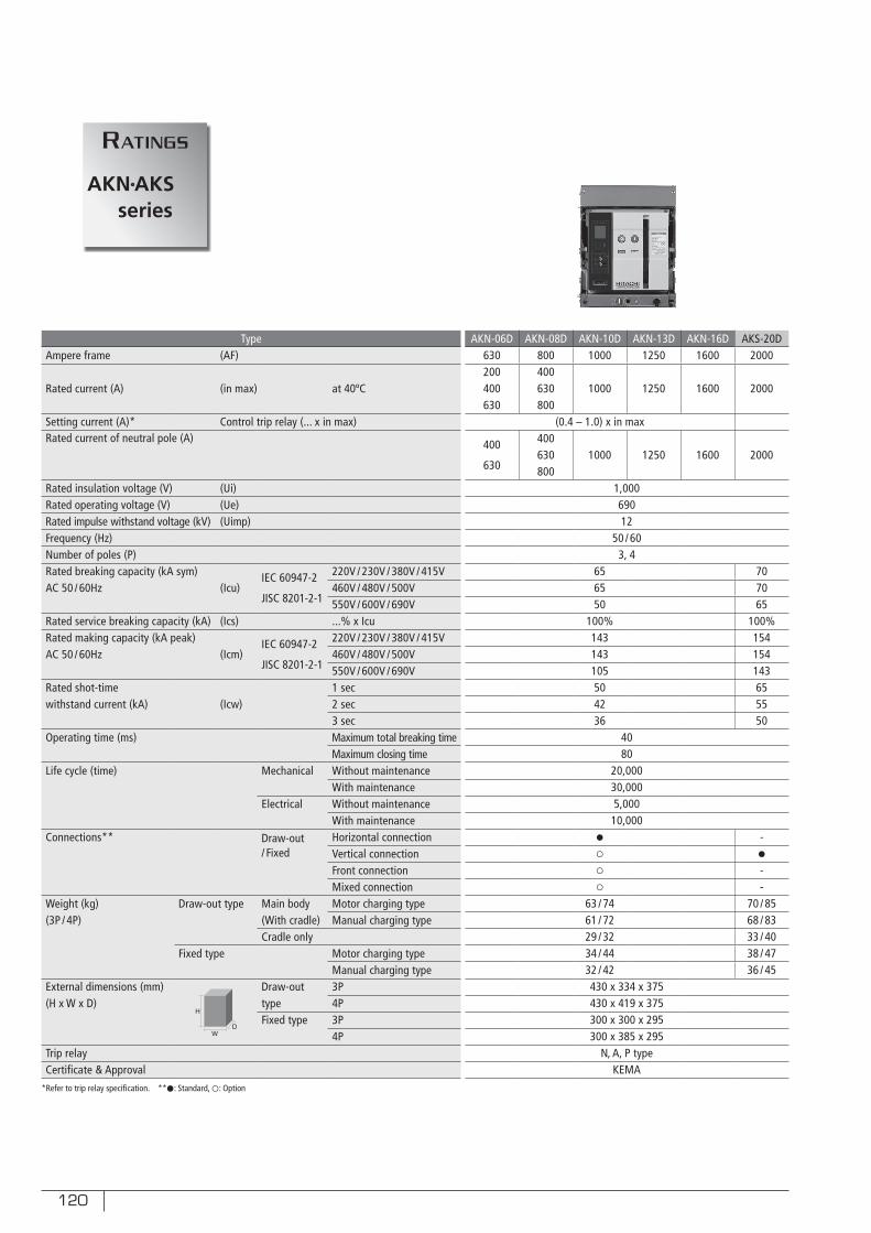
120
TypeAmpere frame (AF)
Rated current (A) (in max) at 40ºC
Setting current (A)* Control trip relay (... x in max)Rated current of neutral pole (A)
Rated insulation voltage (V) (Ui)Rated operating voltage (V) (Ue)Rated impulse withstand voltage (kV) (Uimp)Frequency (Hz)Number of poles (P)Rated breaking capacity (kA sym)
(Icu)IEC 60947-2
JISC 8201-2-1
220V / 230V / 380V / 415VAC 50 / 60Hz 460V / 480V / 500V
550V / 600V / 690VRated service breaking capacity (kA) (Ics) ...% x IcuRated making capacity (kA peak) IEC 60947-2
JISC 8201-2-1
220V / 230V / 380V / 415VAC 50 / 60Hz (Icm) 460V / 480V / 500V
550V / 600V / 690VRated shot-time 1 secwithstand current (kA) (Icw) 2 sec
3 secOperating time (ms) Maximum total breaking time
Maximum closing timeLife cycle (time) Mechanical Without maintenance
With maintenanceElectrical Without maintenance
With maintenanceConnections** Draw-out
/ FixedHorizontal connectionVertical connectionFront connectionMixed connection
Weight (kg) Draw-out type Main body Motor charging type(3P / 4P) (With cradle) Manual charging type
Cradle onlyFixed type Motor charging type
Manual charging typeExternal dimensions (mm) Draw-out 3P(H x W x D) type 4P
Fixed type 3P4P
Trip relayCertifi cate & Approval
AKN-06D AKN-08D AKN-10D AKN-13D AKN-16D AKS-20D630 800 1000 1250 1600 2000200 400400 630 1000 1250 1600 2000630 800
(0.4 – 1.0) x in max
400
630
400630 1000 1250 1600 2000800
1,00069012
50 / 603, 4
65 7065 7050 65
100% 100%143 154143 154105 14350 6542 5536 50
4080
20,00030,0005,000
10,000● -○ ●
○ -○ -
63 / 74 70 / 8561 / 72 68 / 8329 / 32 33 / 4034 / 44 38 / 4732 / 42 36 / 45430 x 334 x 375430 x 419 x 375300 x 300 x 295300 x 385 x 295
N, A, P typeKEMA
*Refer to trip relay specifi cation. **●: Standard, ○: Option
RATinGs
AKN AKSseries
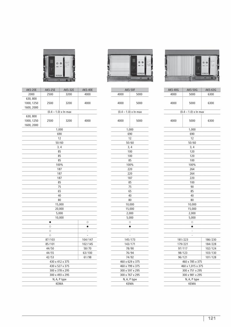
121
AKS-20E AKS-25E AKS-32E AKS-40E2000 2500 3200 4000
630, 8001000, 1250 2500 3200 40001600, 2000
(0.4 – 1.0) x In max630, 800
1000, 1250 2500 3200 40001600, 2000
1,00069012
50 / 603, 4858585
100%1871871878575654080
15,00020,0005,000
10,000● ○
○ ●
○ -○ -
87 / 103 104 / 14785 / 101 102 / 14544 / 50 58 / 7044 / 55 63 / 10042 / 53 61 / 98
430 x 412 x 375430 x 527 x 375300 x 378 x 295300 x 493 x 295
N, A, P typeKEMA
AKS-50F4000 5000
4000 5000
(0.4 – 1.0) x In max
4000 5000
1,00069012
50 / 603, 410010085
100%2202201878575654080
10,00015,0002,0005,000
○
●
--
145 / 173143 / 171
78 / 9076 / 9474 / 92
460 x 629 x 375460 x 799 x 375300 x 597 x 295300 x 767 x 295
N, A, P typeKEMA
AKS-40G AKS-50G AKS-63G4000 5000 6300
4000 5000 6300
(0.4 – 1.0) x In max
4000 5000 6300
1,00069012
50 / 603, 4120120100
100%26426422010090854080
10,00015,0002,0005,000
○
●
--
181 / 223 186 / 230179 / 221 184 / 22897 / 117 102 / 12498 / 123 103 / 13096 / 121 101 / 128
460 x 785 x 375460 x 1,015 x 375300 x 751 x 295300 x 981 x 295
N, A, P typeKEMA
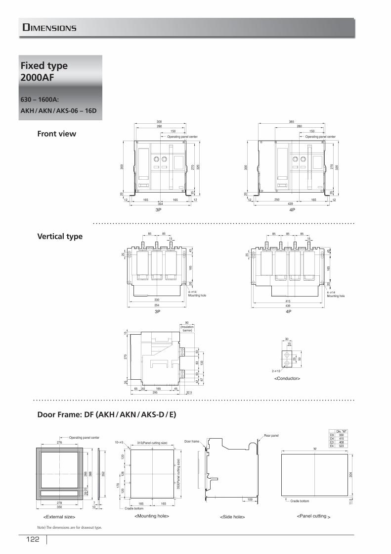
122
Front view
Vertical type
Door Frame: DF (AKH/AKN/AKS-D/E)
Note) The dimensions are for drawout type.
Dimensions
Fixed type 2000AF
630 – 1600A:
AKH/AKN/AKS-06 – 16D
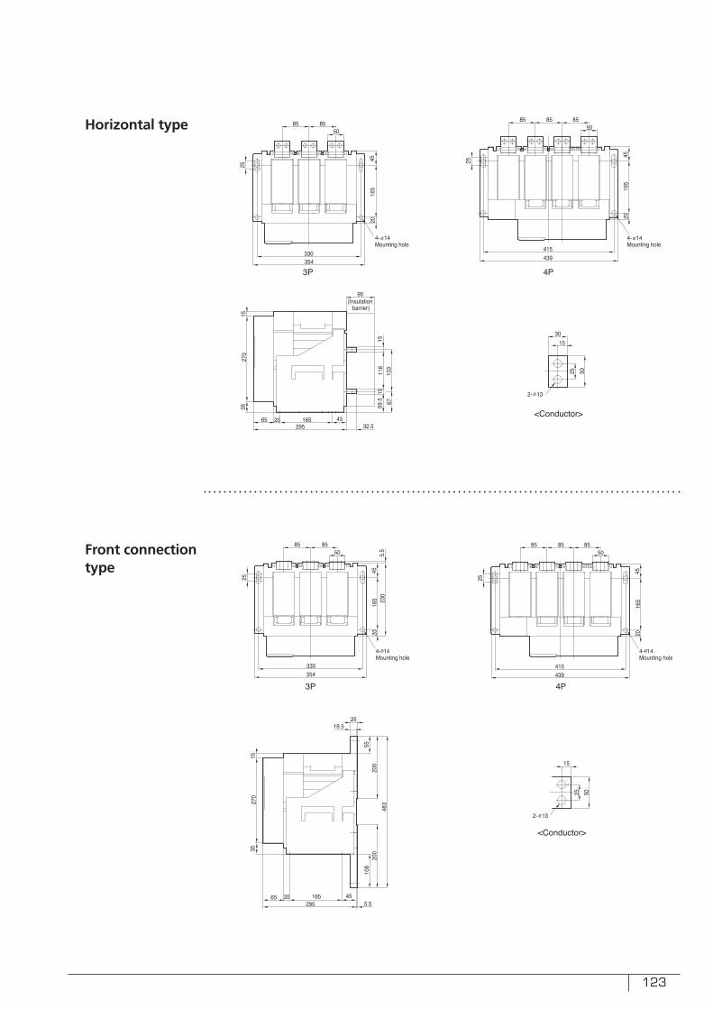
123
Horizontal type
Front connectiontype
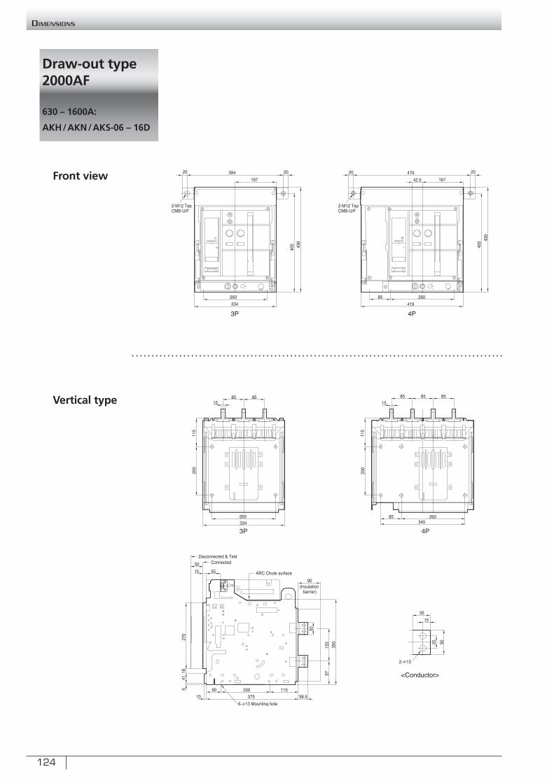
124
Front view
Vertical type
Draw-out type 2000AF
630 – 1600A:
AKH/AKN/AKS-06 – 16D
Dimensions
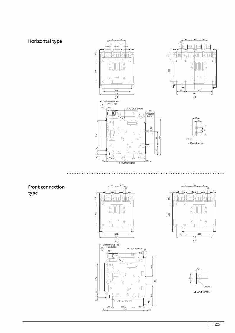
125
Horizontal type
Front connectiontype
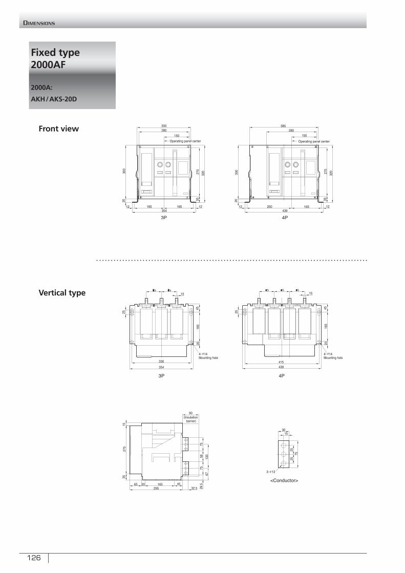
126
Fixed type 2000AF
2000A:
AKH/AKS-20D
Dimensions
Front view
Vertical type
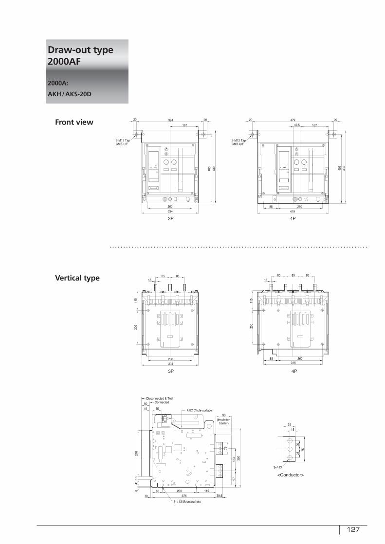
127
Draw-out type 2000AF
2000A:
AKH/AKS-20D
Front view
Vertical type
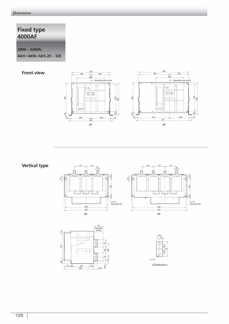
128
Fixed type 4000AF
2000 – 3200A:
AKH/AKN/AKS-20 – 32E
Dimensions
Front view
Vertical type
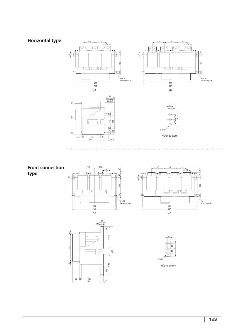
129
Horizontal type
Front connectiontype
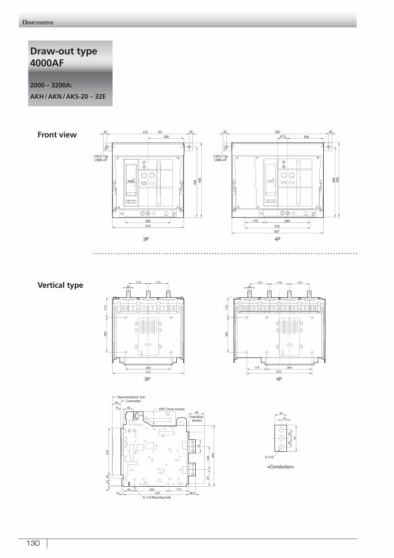
130
Draw-out type 4000AF
2000 – 3200A:
AKH/AKN/AKS-20 – 32E
Dimensions
Front view
Vertical type
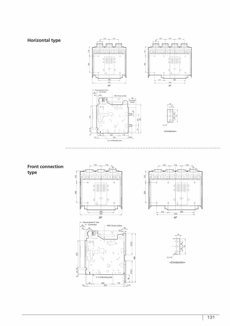
131
Horizontal type
Front connectiontype
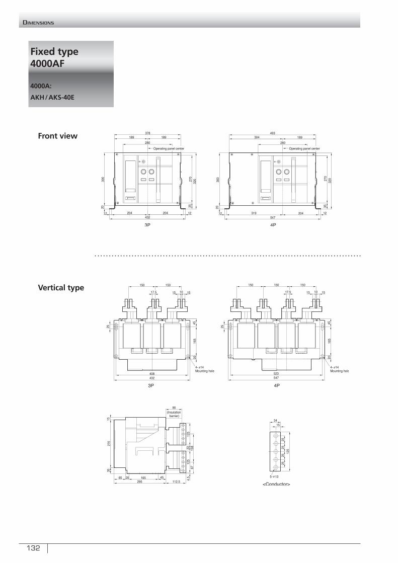
132
Fixed type 4000AF
4000A:
AKH/AKS-40E
Dimensions
Front view
Vertical type
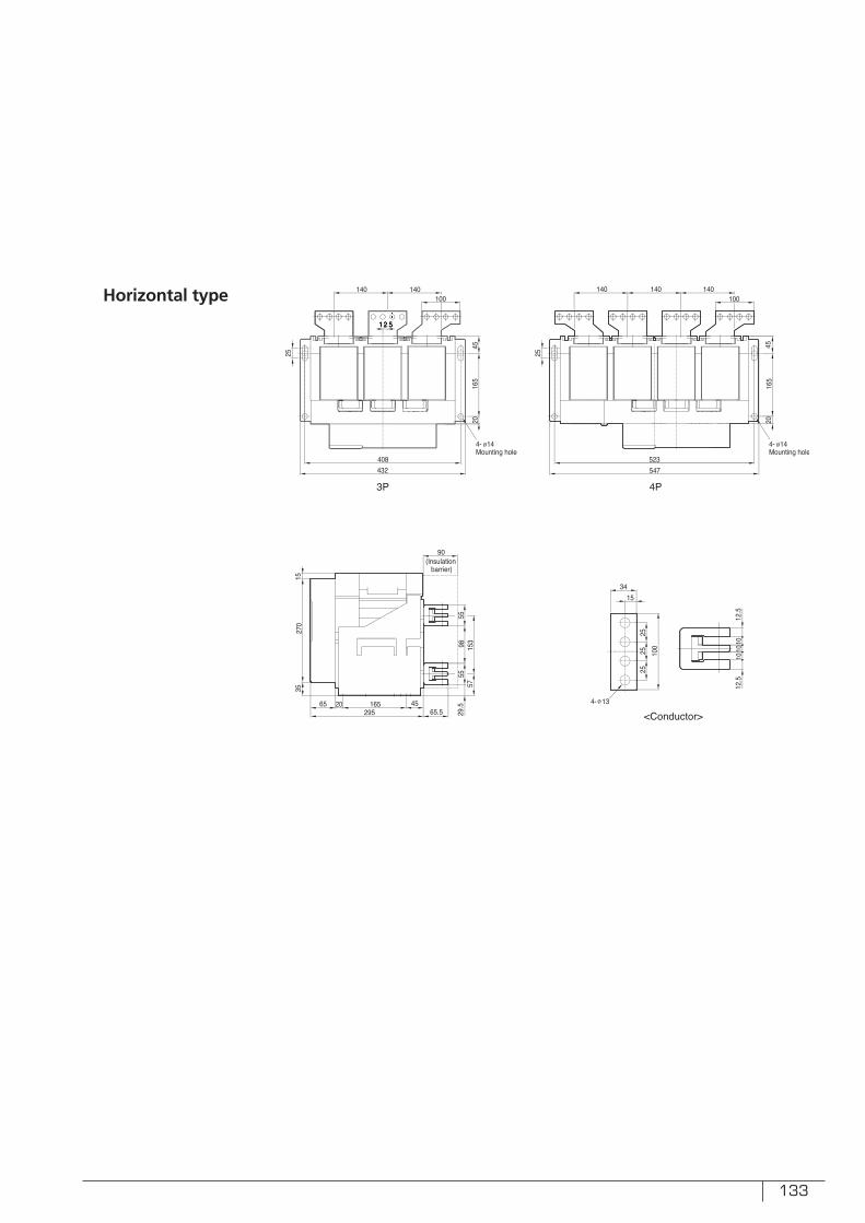
133
Horizontal type
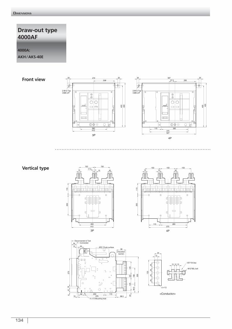
134
Draw-out type 4000AF
4000A:
AKH/AKS-40E
Dimensions
Front view
Vertical type
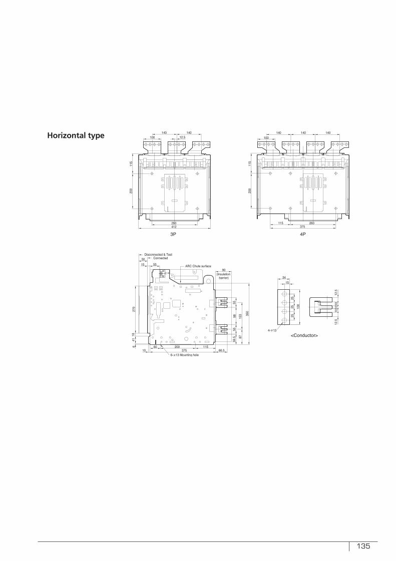
135
Horizontal type
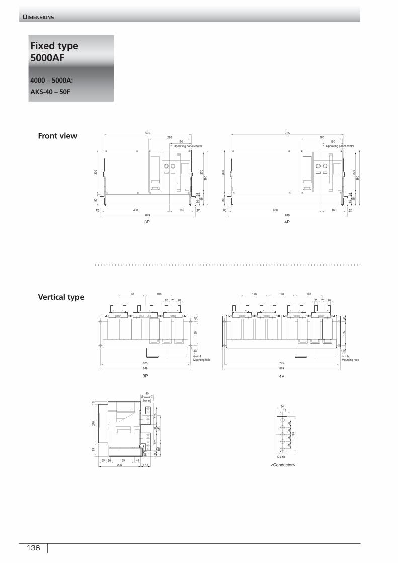
136
Fixed type 5000AF
4000 – 5000A:
AKS-40 – 50F
Dimensions
Front view
Vertical type
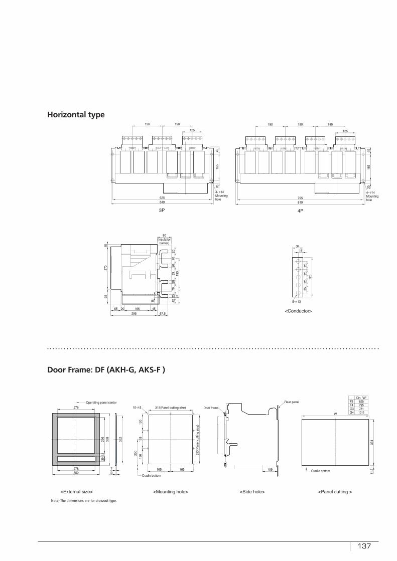
137
Door Frame: DF (AKH-G, AKS-F )
Note) The dimensions are for drawout type.
18
Horizontal type
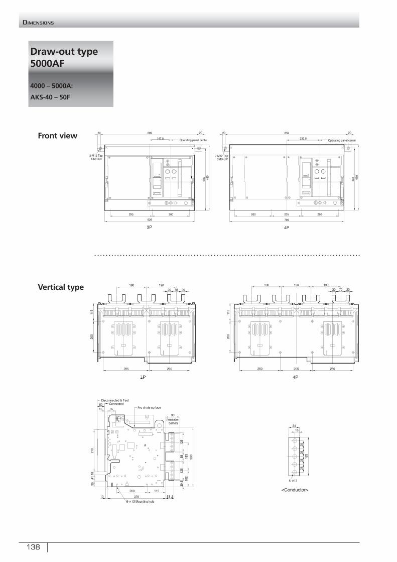
138
Draw-out type 5000AF
4000 – 5000A:
AKS-40 – 50F
Dimensions
Front view
Vertical type
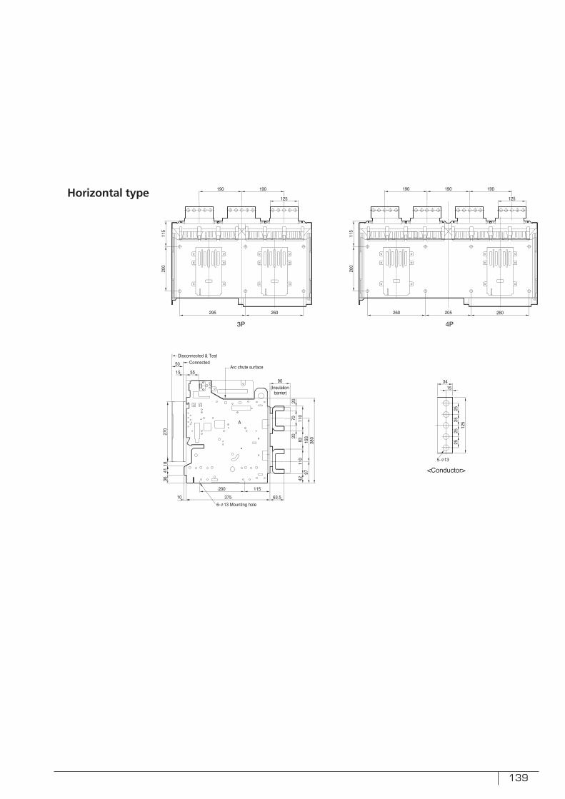
139
Horizontal type
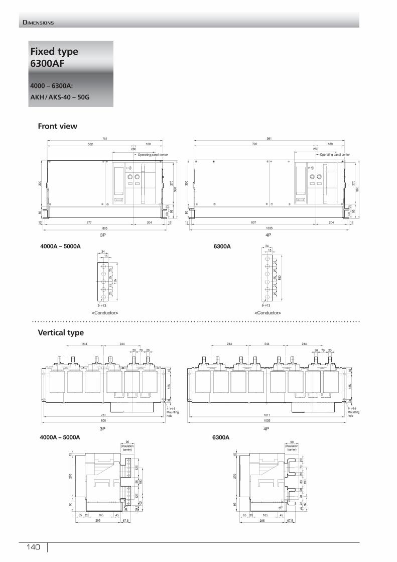
140
Fixed type 6300AF
4000 – 6300A:
AKH/AKS-40 – 50G
Dimensions
Front view
Vertical type
4000A – 5000A 6300A
4000A – 5000A 6300A
18
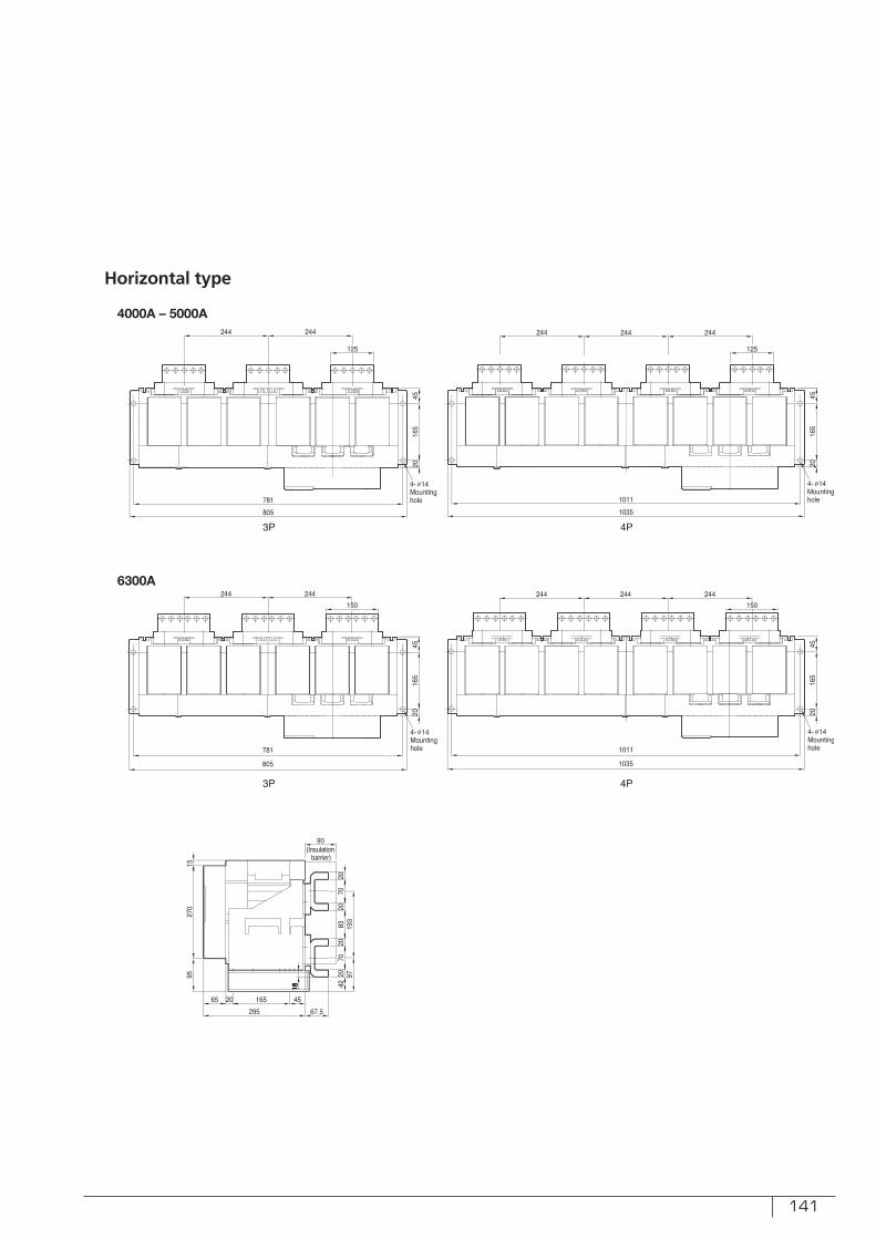
141
Horizontal type
4000A – 5000A
6300A

142
Draw-out type 6300AF
4000 – 6300A:
AKH/AKS-40 – 50G
Dimensions
Front view
Vertical type
6300A4000A – 5000A
6300A4000A – 5000A

143
Horizontal type
6300A
4000A – 5000A

144
memo
Recommended