CIE S 025: Test Method for LED Lamps,
LED Luminaires and LED Modules
Tony Bergen
Secretary, Division 2, International Commission on Illumination (CIE)
Technical Director, Photometric Solutions International Pty Ltd

The contents of many of the slides in this presentation were
provided by Dr Yoshi Ohno, National Institute of Standards
and Technology (NIST), the US Department of Commerce
Acknowledgement
UNEP-lites.asia MVE webinar, 7 May 2015
2

Background and purpose of CIE S 025
What measurements it covers
Standard test conditions and tolerance interval
Operating conditions for device under test
Requirements for test equipment
Reporting uncertainties of measurement
Outline
UNEP-lites.asia MVE webinar, 7 May 2015
3

Background and purpose of CIE S 025
What measurements it covers
Standard test conditions and tolerance interval
Operating conditions for device under test
Requirements for test equipment
Reporting uncertainties of measurement
Outline
UNEP-lites.asia MVE webinar, 7 May 2015
4

Importance of Quality Assurance of SSL
Products
UNEP-lites.asia MVE webinar, 7 May 2015
Problems
• Some very low quality products in the market (dim, short life, bad colour)
• Inaccurate performance claims
• Insufficient product information (label)
• Consumers’ disappointment
• Delay of adoption of SSL
Various Solid State Lighting (SSL) products are
introduced in many countries
Needs for good standards and regulations
5

Need for International Harmonisation in
SSL Testing and Accreditation: Historical
UNEP-lites.asia MVE webinar, 7 May 2015
LM-79
Manufacturers
& Testing labs
PT by NIST
for LM-79
Manufacturers
& Testing labs Manufacturers
& Testing labs
EN Test
Method JIS Test
Methods
NVLAP and other
SSL testing acc.
PT for
EN T.M.
PT for
JIS T.M.
Acc. Prog. for
SSL testing
IA-JAPAN SSL
testing acc.
Chinese CQC
and GB stds
Chinese
regulations
Manufacturers
& Testing labs
PT for
Chinese T.M.
CNAS SSL
testing acc.
Eco-
design
Energy
Label
Test
reports
JAPAN
Eco mark
Top Runner
DOE new
lighting
products
regulations
6

Needs for International Harmonisation in
SSL Testing and Accreditation: Now
UNEP-lites.asia MVE webinar, 7 May 2015
International
Test Method
Manufacturers &
Testing labs
PT for
CIE S 025
Manufacturers &
Testing labs Manufacturers &
Testing labs
International
Test Method International
Test Method
NVLAP and other
SSL testing acc.
International
Test Method
Chinese
regulations
Manufacturers &
Testing labs
Eco-
design
Eco
mark
Energy
Label
CIE S 025
Mutual
recognition Accreditation
for SSL testing
CNAS SSL
testing acc. IA-JAPAN SSL
testing acc.
PT for
CIE S 025
PT for
CIE S 025
PT for
CIE S 025 Shared
DOE new
lighting
products
regulations
7
CIE standard S 025 provides a unified
global test method for harmonisation of
testing of LEDs and SSL products
UNEP-lites.asia MVE webinar, 7 May 2015
8

CIE is the International Commission on Illumination
(Commission Internationale de l'Eclairage)
An independent, non-profit organisation recognised by the
ISO as an international standardisation body in the field of
light and lighting
The CIE is about...
LIGHT & VISION & COLOUR
SCIENCE & STANDARDS
KNOWLEDGE TRANSFER & QUALITY ASSURANCE
The CIE has been working for over 100 years
Who is the CIE??
UNEP-lites.asia MVE webinar, 7 May 2015
9

CIE Division 2 deals with physical measurement of light and
radiation
CIE TC2-71 CIE Standard on Test Methods for LED Lamps,
Luminaires and Modules
Established in 2011
Chair: Dr. Yoshi Ohno (NIST, USA)
The TC has 37 members from 16 countries in 5 continents:
globally representative
Standard was published in March 2015:
CIE S 025/E:2015 Test Method for LED Lamps, LED
Luminaires and LED Modules
CIE Technical Committee TC2-71
UNEP-lites.asia MVE webinar, 7 May 2015
10

CIE TC2-71 and CEN TC169 WG7
UNEP-lites.asia MVE webinar, 7 May 2015
EN 13032 Lighting Applications — Measurement and Presentation of
Photometric Data of Lamps and Luminaires — Part 4: LED Lamps, Modules
and Luminaires
CIE TC2-71 CIE Standard on test methods for LED Lamps,
luminaires and modules Chair, Yoshi Ohno (US)
Joint work with
CEN TC169 WG7 Photometry, Chair, Guy Vandermeersch (BE)
CIE S 025/E:2015 Test Method for LED Lamps, LED
Luminaires and LED Modules Published 2015.3.20
In final approval process
11

IESNA LM-79-08 was one of the first test methods for SSL devices
It became a default global test standard for SSL measurement
However, LM-79 was developed by a regional organisation: many
national standards could not adopt this
CIE S 025 draws on the experience of LM-79:
it is more comprehensive; covers more measurement instruments; and
has greater depth
S 025 development was globally representative
S 025 was developed by CIE, a recognised international standards
organisation
National and regional standardising bodies and regulators should
now move to adopting S 025 for LED measurement
CIE S 025 and LM-79
UNEP-lites.asia MVE webinar, 7 May 2015
12

Background and purpose of CIE S 025
What measurements it covers
Standard test conditions and tolerance interval
Operating conditions for device under test
Requirements for test equipment
Reporting uncertainties of measurement
Outline
UNEP-lites.asia MVE webinar, 7 May 2015
13

Products covered:
LED lamps
LED luminaires
LED modules
Products not covered:
LED packages
OLED products
What it Covers
UNEP-lites.asia MVE webinar, 7 May 2015
14

Total luminous flux
Partial luminous flux (useful lumens)
Centre beam and beam angles
Electrical measurements
Luminous efficacy (efficiency)
Luminous intensity distribution
Chromaticity coordinates
Correlated colour temperature
Distance from Planckian locus
Colour rendering indices
Angular colour uniformity
Measurements it Covers
UNEP-lites.asia MVE webinar, 7 May 2015
15

The Standard does not cover or only partially covers:
Dimmable, internal feedback, adjustable colour, adjustable white, multicolour
Maintained luminous flux
Omni-directional assessment
Maintained colour measurements
Harmonics & EMC
Start time / activation time
Switch withstand
Lamp Life
Temperature cycling shock
Endurance
Photobiological hazards
Flicker
Dimmer compatibility
Note: Many of these are already covered satisfactorily in other Standards
What it Doesn’t Cover
UNEP-lites.asia MVE webinar, 7 May 2015
16

Background and purpose of CIE S 025
What measurements it covers
Standard test conditions and tolerance interval
Operating conditions for device under test
Requirements for test equipment
Reporting uncertainties of measurement
Outline
UNEP-lites.asia MVE webinar, 7 May 2015
17

4.1 General
4.1.1 Standard Test Conditions
Measurements of the photometric, colorimetric
and electrical characteristics of a LED device
shall be performed by means of appropriate
equipment and procedures under defined
standard test conditions for operation of the DUT
(Device Under Test). A standard test condition
includes a set value and a tolerance interval.
Measurement results are expressed for the set
value of the standard test conditions.
Standard test conditions and tolerance interval
UNEP-lites.asia MVE webinar, 7 May 2015
Set
value
Tolerance
interval
18

Standard Test Conditions
UNEP-lites.asia MVE webinar, 7 May 2015
Ambient temperature (LED lamps, luminaires)
25 °C ±1.2 °C
Surface temperature (LED module) ±2.5 °C from
specified tp
Air movement 0 to 0.25 m/s
Test voltage ± 0.4 % from rated supply voltage
Set value ± tolerance interval
(For operation of DUT)
19

What is the uncertainty of your instrument (eg: thermometer,
anemometer)?
How does the uncertainty affect the tolerance interval?
Need to Consider
UNEP-lites.asia MVE webinar, 7 May 2015
4.1.2 Tolerance Interval
The measurement uncertainty of the related parameter shall be taken
into account to ensure that the parameter is within the tolerance
interval. For this purpose, an acceptance interval is defined as the
tolerance interval reduced by the expanded uncertainty (95%
confidence) of the measurement of the parameter on both limits of the
tolerance.
20

Tolerance Interval and Acceptance Interval
UNEP-lites.asia MVE webinar, 7 May 2015
Annex A
Tolerance Interval
“tolerance interval” defined in ISO/IEC Guide 98-4 Role of measurement
uncertainty in conformity assessment.
Tolerance interval is an acceptable range of the true value of the parameter (not
the range of readings of instrument). Therefore, to ensure this requirement is
fulfilled, measurement uncertainty of the parameter needs to be taken into
account.
21

Tolerance Interval and Acceptance Interval
UNEP-lites.asia MVE webinar, 7 May 2015
22

Examples of Acceptance Intervals
UNEP-lites.asia MVE webinar, 7 May 2015
Tolerance
Interval Instrument
uncertainty
(k=2)
Acceptance
interval
Ambient temperature ± 1.2 oC 0.2
oC
0.5 oC
± 1.0 oC
± 0.7 oC
Surface temperature
(LED module)
± 2.5 oC 0.5
oC ± 2.0
oC
Air movement speed ± 0.25 m/s 0.05 m/s ± 0.20 m/s
Supply voltage (AC) ± 0.4 % 0.2 % ± 0.2 %
(DC) ± 0.2 % 0.1 % ± 0.1 %
(example values only)
• There are no requirements for the instrument uncertainties
• The larger the uncertainty, the smaller the acceptance interval
23

Tolerance Interval and Acceptance Interval
UNEP-lites.asia MVE webinar, 7 May 2015
3.38
tolerance interval
interval of permissible values of a property
Note 1 to entry: Unless otherwise stated in a specification, the tolerance limits belong to the
tolerance interval.
Note 2 to entry: The term “tolerance interval“ as used in conformity assessment has a
different meaning from the same term as it is used in statistics.
[SOURCE: ISO/IEC Guide 98-4, 3.3.5]
3.39
acceptance interval
interval of permissible measured quantity values
Note 1 to entry: Unless otherwise stated in the specification, the acceptance limits belong to
the acceptance interval.
[SOURCE: ISO/IEC Guide 98-4, 3.3.9]
24

Outside the Tolerance Interval
UNEP-lites.asia MVE webinar, 7 May 2015
4.1 General
4.1.1 Standard Test Conditions
In case where some of the standard test conditions
or requirements cannot be fulfilled, deviations
outside the tolerance intervals or requirements are
permitted if the related measurements are
corrected to the standard test conditions. In such
cases, the specific uncertainty component for the
corrected parameter shall be evaluated and
incorporated into the final uncertainty budget. The
actual measurement condition and the fact that
correction is made to the standard test condition for
the parameter shall be reported in the test report.
Set
value
Tolerance
interval
Measured
parameter
value
25

Correction to the Standard Condition
UNEP-lites.asia MVE webinar, 7 May 2015
4.1 General
4.1.1 Standard Test Conditions
(Even if the tolerance is met) To further reduce
the uncertainty of measurements, the results
may be corrected for the deviation within the
tolerance interval, to conditions at the set value
of the standard test condition. The set value is
normally the centre value of the tolerance
interval, though not always so.
Set
value
Tolerance
interval
Measured
parameter
value
26

Direct Correction of the Measurement Result
UNEP-lites.asia MVE webinar, 7 May 2015
Example: In a goniophotometric measurement, room temperature = 27.3 oC
Use a temperature controlled chamber and a luminance meter to make a
correction factor to correct the measured result to what it would be at 25.0 oC
27

Correction Using Sensitivity Coefficient
UNEP-lites.asia MVE webinar, 7 May 2015
Sensitivity coefficient
= -0.5% / oC
Set value = 25 oC Measured value = 27.3
oC
Measured luminous flux: F = 1243 lm
Corrected luminous flux: F (25 oC) = 1257 lm
0.96
0.97
0.98
0.99
1.00
1.01
1.02
1.03
1.04
1.05
15 20 25 30 35
Re
lati
ve
lu
min
ou
s f
lux
Ambient temperature (oC)
28

Background and purpose of CIE S 025
What measurements it covers
Standard test conditions and tolerance interval
Operating conditions for device under test
Requirements for test equipment
Reporting uncertainties of measurement
Outline
UNEP-lites.asia MVE webinar, 7 May 2015
29

Temperature Conditions for Operation of DUT
UNEP-lites.asia MVE webinar, 7 May 2015
LED Lamps
LED lamps are measured in standard test conditions and data shall be reported
for tamb = 25 oC. If other operating temperatures are declared by the manufacturer,
the measured results at the given temperature shall be reported or a service
conversion factor shall be provided.
LED Modules
LED modules are measured in standard test conditions at the rated performance
temperature tp. The temperature at the tp-point shall be set at this value for the
measurements. …… a suitable temperature controlled heat sink may be used.
Interpolation techniques may also be applied (see Annex C).
LED Luminaires
LED luminaires are measured in standard test conditions at tamb = 25 oC.
30
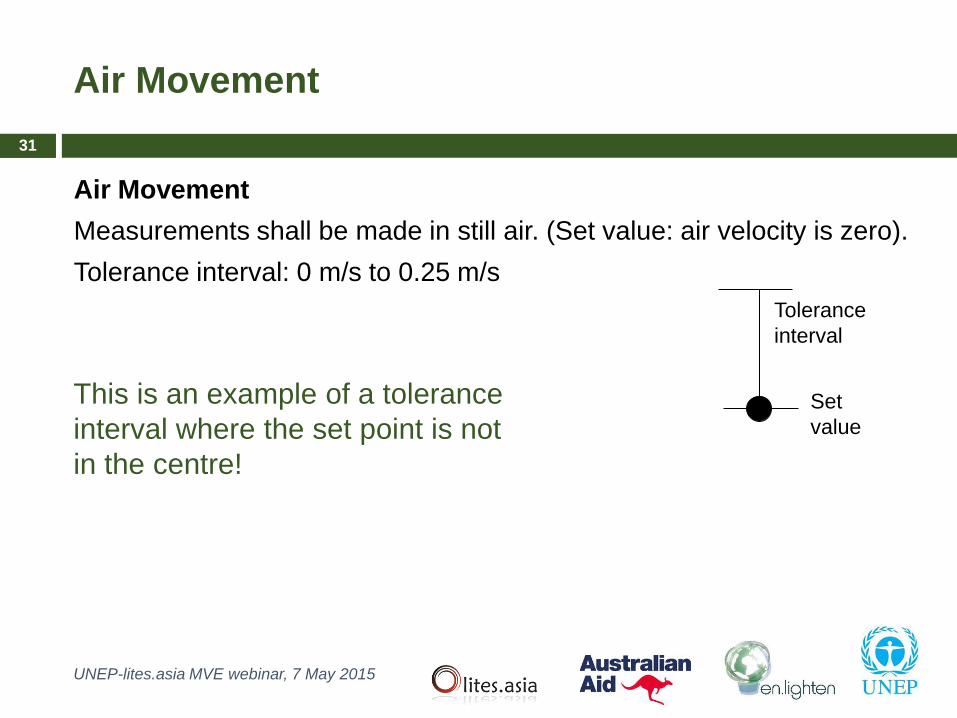
Air Movement
Measurements shall be made in still air. (Set value: air velocity is zero).
Tolerance interval: 0 m/s to 0.25 m/s
Air Movement
UNEP-lites.asia MVE webinar, 7 May 2015
This is an example of a tolerance
interval where the set point is not
in the centre!
Set
value
Tolerance
interval
31

Operating Position of Device Under Test (DUT)
UNEP-lites.asia MVE webinar, 7 May 2015
Operating Position
Specific requirement: The DUT shall remain in its designed
operating condition (with respect to gravity direction) throughout the
stabilization and testing period.
If this requirement is not met, the measurements shall be
corrected to the performance in the designed operating position.
32

Stabilization of Device Under Test (DUT)
UNEP-lites.asia MVE webinar, 7 May 2015
LED Lamps and LED Luminaires
The DUT shall be operated (at ambient temperature 25 °C) for at least 30
min and it is considered as stable if the relative difference of maximum
and minimum readings of light output and electrical power observed over
the last 15 minutes is less than 0,5 % of the minimum reading.
30 min 0
15 min
< 0.5 % F P
33

Stabilization of Device Under Test (DUT)
UNEP-lites.asia MVE webinar, 7 May 2015
LED Modules
When the temperature reaches and maintains the specified performance
temperature tp within ±1 oC for 15 min, the LED module is considered to be
stabilized in temperature.
0
15 min
≤ ±1 oC tp
tp
The temperature of LED modules is commonly adjusted using a temperature-
controlled heat sink.
34

Background and purpose of CIE S 025
What measurements it covers
Standard test conditions and tolerance interval
Operating conditions for device under test
Requirements for test equipment
Reporting uncertainties of measurement
Outline
UNEP-lites.asia MVE webinar, 7 May 2015
35

Laboratory Requirements for Tests
UNEP-lites.asia MVE webinar, 7 May 2015
All measurements shall be traceable to the SI* when
instruments are used to measure absolute values of a
quantity relevant to the measurement.
3.37
traceability
property of a measurement result whereby the result can be
related to a reference (usually NMI’s calibration) through a documented
unbroken chain of calibrations, each contributing to the
measurement uncertainty.
36
* Note: SI is an abbreviation for Système International d’Unités (International System
of Units) is defined by the CGPM (General Conference of Weights and Measure) and
includes the units used internationally today.

Electrical Test Conditions and Electrical
Equipment
UNEP-lites.asia MVE webinar, 7 May 2015
Specific requirements (summary)
Calibration uncertainty of AC Voltmeters and ammeters ≤ 0.2 % for
AC, ≤ 0.1 % for DC
Calibration uncertainty of AC power meter ≤ 0.5 %
Bandwidth of AC power meter ≥ 100 kHz.
Internal impedance of the voltage measurement: ≥ 1 MW
AC power supply THD ≤ 1.5% (≤ 3 % for PF > 0.9) at DUT terminal
AC power supply frequency uncertainty ≤ 0.2 %
DC power supply voltage AC ripple ≤ 0.5 %
37

Electrical Test Conditions and Electrical
Equipment
UNEP-lites.asia MVE webinar, 7 May 2015
The voltage of the AC power supply shall be regulated (tested) at the
supply terminals of the DUT. (not at the output terminal of power
supply. Cables included).
Specific requirement: Any drift or fluctuation of the supply voltage during
measurement of a DUT shall be within the acceptance interval of the
test voltage (4.3.1).
38

Photometric and Colorimetric Measurement
Instruments
UNEP-lites.asia MVE webinar, 7 May 2015
Integrating sphere systems:
• Sphere-photometer (photometer head as detector)
• Sphere-spectroradiometer (spectroradiometer as detector)
Goniophotometer systems:
• Goniophotometer (photometer head as detector)
• Gonio-spectroradiometer (spectroradiometer as detector)
• Gonio-colorimeter (tristimulus colorimeter as detector)
Other types of measurement instruments including integrating hemisphere,
near-field goniophotometer and ILMD, are acceptable if they are
demonstrated to produce equivalent results as a conventional integrating
sphere system or conventional goniophotometer system.
39

Photometric and Colorimetric Measurement
Instruments
UNEP-lites.asia MVE webinar, 7 May 2015
Specific requirements (summary)
f1’ of the photometer system (gonio, sphere) ≤ 3 %
f2 of the detector head of sphere system ≤ 15%
Repeatability of sphere (open/close) ≤ 0.5 %
Stability of the sphere between recalibrations ≤ 0.5 %
Spectroradiometer bandwidth and interval ≤ 5 nm
Spectroradiometer wavelength uncertainty ≤ 0.5 nm
Angle uncertainty of goniophotometers ≤ 0.5 °
40

Covers both 4 and 2 integrating sphere systems
Integrating Sphere Measurements
UNEP-lites.asia MVE webinar, 7 May 2015
From IES LM-79
<4 geometry> <2 geometry>
41

Gives guidance for:
Self-absorption measurements
Size of DUT with respect to size of sphere
Orientation of DUT in sphere
Sphere reflectance uniformity
Cosine response
Repeatability of closure
Calibration interval
Spectral responsivity (including coating reflectance)
Integrating Sphere Measurements
UNEP-lites.asia MVE webinar, 7 May 2015
42

Gives guidance for:
Angular scan range and dead angle
Angular aiming and accuracy
Stray light
Spectral responsivity (including mirror reflectance)
Test distance for far-field measurements (see next slide)
Goniophotometer Measurements
UNEP-lites.asia MVE webinar, 7 May 2015
43

Distance requirements for goniophotometers
UNEP-lites.asia MVE webinar, 7 May 2015
Luminous intensity measurements according to the inverse square law require a sufficient photometric
distance.
Specific requirements for test distance in far-field photometry:
− For DUT having near cosine (Lambertian) distribution (beam angle ≥ 90°) in all C-planes: ≥ 5 × D
− For DUT having a broad angular distribution different from a cosine distribution (beam angle ≥ 60°)
in some of the C-planes: ≥ 10 × D
− For DUT with narrower angular distributions , steep gradients in the luminous intensity distribution or
critical glare control: ≥ 15 × D
− For DUT where there are large non-luminous spaces between the luminous areas: ≥ 15 × (D+S)
where D is the maximal luminous dimension of the DUT and S is the largest distance between two
adjacent luminous areas.
44

Background and purpose of CIE S 025
What measurements it covers
Standard test conditions and tolerance interval
Operating conditions for device under test
Requirements for test equipment
Reporting uncertainties of measurement
Outline
UNEP-lites.asia MVE webinar, 7 May 2015
45

It is a simple fact of life that no measurement is ever perfect
For each measurement there is an uncertainty of
measurement, which is like an estimate of the possible error
that could be associated with the measurement result
CIE S 025 requires that all measurement reports shall
include a statement of uncertainties of measurement
Reporting of Measurement Uncertainties
UNEP-lites.asia MVE webinar, 7 May 2015
46

A statement of uncertainties consists of a magnitude and an
associated probability
“The measured luminous flux is 783 lm ± 4.2% with a
coverage factor k = 2”
“The correlated colour temperature is 3012 K ± 55 K with a
confidence interval of 95%”
Reporting of Measurement Uncertainties
UNEP-lites.asia MVE webinar, 7 May 2015
Magnitude
May be relative (eg: 5%)
May be absolute (eg: 14 lm)
Probability
May be a coverage probability, eg: 95%
May be a coverage factor, eg: k = 2
47

Ideally, for best practice, measurement uncertainties would
be evaluated for each test
However for practical purposes, it is permitted to use
uncertainty values for a typical product of the similar type,
with a statement that indicates so in the test report
If a lab does this, they must keep a detailed uncertainty
budget and evidence of how they evaluated this “typical”
product
Reporting of Measurement Uncertainties
UNEP-lites.asia MVE webinar, 7 May 2015
48

The measurement uncertainties shall be evaluated according
to ISO/IEC Guide 98-3 and its supplements
Guidance for evaluating measurement uncertainties for LED
lighting devices is given in Chapter 8 and Annex D of
CIE S 025
Guidance is also available in CIE 198:2011 “Determination of
Measurement Uncertainties in Photometry” and its
supplements
Reporting of Measurement Uncertainties
UNEP-lites.asia MVE webinar, 7 May 2015
49

CIE has recently published the Standard CIE S 025/E:2015,
which is a standard test method for photometric testing of
LED lamps, luminaires and modules
CIE S 025 can be used for worldwide harmonised testing of
LED lighting products
It contains test conditions and requirements for equipment
used to perform the tests
It requires mandatory reporting of measurement uncertainties
Standardising bodies and regulators are encouraged to move
to adopting CIE S 025 for LED measurement
http://div2.cie.co.at/?i_ca_id=563&pubid=491
Summary
UNEP-lites.asia MVE webinar, 7 May 2015
50

CIE’s 28th Quadrennial Session, Manchester/UK, June 28 -
July 4, 2015
CIE Lighting Quality and Energy Efficiency Conference,
Melbourne/Australia, March 3-5, 2016
More information: http://www.cie.co.at/
Upcoming CIE Conferences
UNEP-lites.asia MVE webinar, 7 May 2015
51

Thank you for your kind attention.
Any questions?
Tony Bergen
UNEP-lites.asia MVE webinar, 7 May 2015
52
Recommended


![LED MEASUREMENT ISSUES* - Gooch & Housego MEASUREMENT ISSUES* ... CIE TC 2-46 [6ii, Draft 4 May 2001]: LED front tip: The LED front tip is center point of the LED light emitting surface](https://img.pdfslide.us/doc/110x75/5b095ef47f8b9a3d018d9d8f/led-measurement-issues-gooch-housego-measurement-issues-cie-tc-2-46-6ii.jpg)