Chapter 5 Spread spectrum
Audio Watermarking
Algorithms
50
Chapter 5 Spread Spectrum Audio Watermarking algorithms
Introduction
Most of the existing audio watermarking techniques embed the watermarks in
the time domain / frequency domain where as there are few techniques which embed
the data in cepstrum or compressed domain. Spread spectrum technique is most
popular technique and is used by many researchers in their implementations [13, 14,
15, 16, 17, 18, 19, 29]. Amplitude scaled Spread Spectrum Sequence is embedded in
the host audio signal which can be detected via a correlation technique. Generally
embedding is based on a psychoacoustic model (which provides inaudible limits of
watermark).
The spread spectrum techniques can be divided in to two categories blind and
non blind techniques. Blind watermarking techniques detect the watermark without
using the original host signal whereas the non blind techniques use the original host
signal to detect the watermark. The most blind watermarking techniques studied in
chapter 2 only detects the presence of the valid watermark and not concentrate on
recovering (extracting) the embedded watermark. Non blind techniques recover the
watermark whereas it requires the original signal to recover the watermark.
Section 5.1 provides the brief overview of conventional spread spectrum
method. Section 5.2 highlights on the non blind technique suggested by Li et al [29]
and implemented in the initial stage of the research to test the watermarking scheme
for our database and then compare the results with our proposed schemes. The results
of this implementation tested for our database are appeared in paper VI. In section 5.3
we propose the adaptive blind watermarking technique based on SNR using DWT and
lifting wavelet transform. The results of these implementations are published partly in
paper VII and paper VIII. To improve the imperceptibility between the original audio
signal and the watermarked audio signal the adaptive SNR based scheme using DWT-
DCT is implemented. Section 5.4 describes this scheme the results of which are
published in paper IX and Paper X. To make the system robust and secure we propose
to embed the watermark using cyclic coding. The scheme which encodes the
watermark using cyclic codes and embeds the watermark is proposed in section 5.5.
51
5.1. Spread Spectrum watermarking: Theoretical background
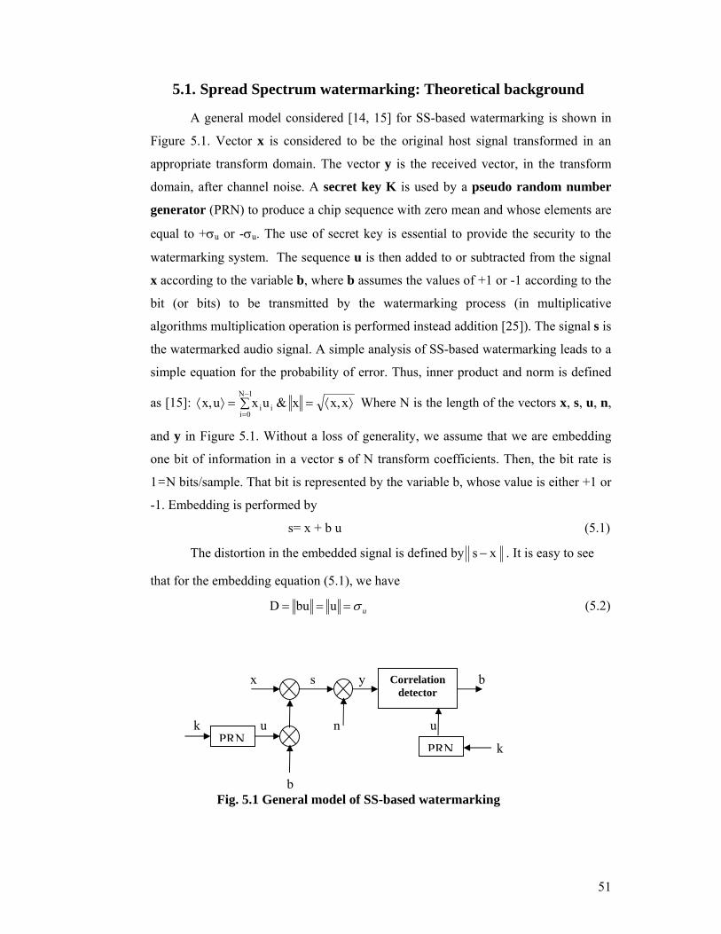
A general model considered [14, 15] for SS-based watermarking is shown in
Figure 5.1. Vector x is considered to be the original host signal transformed in an
appropriate transform domain. The vector y is the received vector, in the transform
domain, after channel noise. A secret key K is used by a pseudo random number
generator (PRN) to produce a chip sequence with zero mean and whose elements are
equal to +σu or -σu. The use of secret key is essential to provide the security to the
watermarking system. The sequence u is then added to or subtracted from the signal
x according to the variable b, where b assumes the values of +1 or -1 according to the
bit (or bits) to be transmitted by the watermarking process (in multiplicative
algorithms multiplication operation is performed instead addition [25]). The signal s is
the watermarked audio signal. A simple analysis of SS-based watermarking leads to a
simple equation for the probability of error. Thus, inner product and norm is defined
as [15]: ⟩⟨=∑=⟩⟨−
=xx,x&uxux,
1N
0iii Where N is the length of the vectors x, s, u, n,
and y in Figure 5.1. Without a loss of generality, we assume that we are embedding
one bit of information in a vector s of N transform coefficients. Then, the bit rate is
1=N bits/sample. That bit is represented by the variable b, whose value is either +1 or
-1. Embedding is performed by
s= x + b u (5.1)
The distortion in the embedded signal is defined by x s − . It is easy to see
that for the embedding equation (5.1), we have
uσ=== ubuD (5.2)
x s y b
k u n u
k b Fig. 5.1 General model of SS-based watermarking
PRNPRN
Correlation detector
52
The channel is modeled as an additive noise channel y = s + n, and the
watermark extraction is usually performed by the calculation of the normalized
sufficient statistics r:
nc++=⟩++⟨
=⟩⟨⟩⟨
= xu
c b un,xbuuu,uy,
rσ
(5.3)
and estimating the embedded bit as sign(r) b̂ = , where uun,
nuux,
x c and c ⟩⟨⟩⟨ == .
Simple statistical models for the host audio x and the attack noise n are assumed.
Namely, both sequences are modeled as uncorrelated white Gaussian random
processes. Then, it is easy to show that the sufficient statistics r is also
Gaussian )σN(0,n and)σN(0,x 2ni
2xi ∼∼ , ~ Sian variable, i.e.:
[ ] 2u
2n
2x2
rr 2rr Nσ
σσσ b, rEm),σ,N(mr
+===∼ (5.4)
Let us consider the case when b is equal to 1. In this case error occurs when r <
0 and therefore, the error probability p is given by
{ } ( ) ⎟⎟⎠
⎞⎜⎜⎝
⎛
+=⎟⎟
⎠
⎞⎜⎜⎝
⎛==<= 2
n2x
2u
r
rr σσ2
Nσerfc21
2σmerfc
211 b0 b̂ P p (5.5)
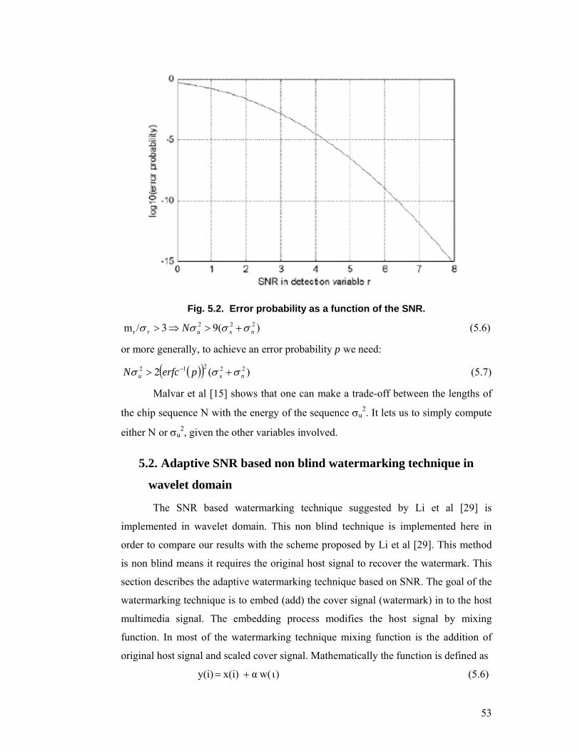
Where erfc(.) is complementary error function. The equal error probability is
obtained under the assumption that b = -1. A plot of that probability as a function of
the SNR (in this case defined as (mr/σr) is given in Figure 5.2. For example, from
Figure 5.2, it can be seen that if an error probability lower than 10-3 is needed, SNR
becomes:
53
Fig. 5.2. Error probability as a function of the SNR.
)(93/m 222r nxur N σσσσ +>⇒> (5.6)
or more generally, to achieve an error probability p we need:
( )( ) )(2 22212nxu perfcN σσσ +> − (5.7)
Malvar et al [15] shows that one can make a trade-off between the lengths of
the chip sequence N with the energy of the sequence σu2. It lets us to simply compute
either N or σu2, given the other variables involved.
5.2. Adaptive SNR based non blind watermarking technique in
wavelet domain
The SNR based watermarking technique suggested by Li et al [29] is
implemented in wavelet domain. This non blind technique is implemented here in
order to compare our results with the scheme proposed by Li et al [29]. This method
is non blind means it requires the original host signal to recover the watermark. This
section describes the adaptive watermarking technique based on SNR. The goal of the
watermarking technique is to embed (add) the cover signal (watermark) in to the host
multimedia signal. The embedding process modifies the host signal by mixing
function. In most of the watermarking technique mixing function is the addition of
original host signal and scaled cover signal. Mathematically the function is defined as
)( += ιwα x(i) y(i) (5.6)
54
Where y(i) is the watermarked signal, x(i) is the original host signal, w(i) the
cover signal and α scaling parameter used as the secret key. The parameter α plays
an important role in embedding and detection process of watermarking. In embedding
process α is selected in such way that the watermark remains imperceptible
(inaudible). The watermark detection process is exactly the reverse process. Without
the knowledge of parameter α it is not possible to detect the watermark. Any
statistical analysis should not leave any possibility of detecting the cover signal or the
parameter α. The imperceptibility of the watermarking procedure is computed by
computing the SNR between the original host signal and the watermarked signal. The
SNR can be computed as
∑
∑
∀
∀
−=
i
i
iyix
ixSNR
2
2
))()((
)(log10 (5.7)
The method proposed by Wu et al [29] is implemented in wavelet domain. To
embed the watermark in to host audio signal the host audio signal is divided in to
smaller segments of size N. One bit of binary watermark is then added in to one
segment of host audio signal.
( )
⎪⎩
⎪⎨
⎧ ⋅α+=
otherwise)i(k3A
)i(Amaxis)i(k3Aif)k(w)k()i(k
3A)i(k
3B3k
(5.8)
Where )i(A3k is cd3 coefficient of 3rd level DWT of )(ixk and )(ixk is ith
sample of kth segment of host audio signal. )i(B3k is watermarked cd3 coefficient.
)k(α is scaling parameter used to scale the watermark bit )k(w so that the added
watermark is inaudible in the audio. The SNR between the original coefficient
)i(A3k and the modified coefficient )i(B3
k can be represented by
( )∑ −
∑=
∀
∀
i
23k
3k
i
23k
)i(B)i(A
)i(Alog10SNR (5.9)
Solving formulas (5.8) and (5.9) for scaling parameter α(k) to obtain
( )( )( )
)k(w
10.iA)k( i
10SNR23k∑
=α
−
(5.10)
55
The value of )k(w2 is =1 because w(k) is either +1 or -1. For the threshold
value of SNR the scaling parameter )k(α required in formula (5.8) can be computed
using this equation and used to embed the watermark. According to IFPI
(International Federation of the Phonographic Industry) [28] the imperceptible audio
watermark scheme requires at least 20 db SNR value between the watermarked signal
and the host signal, so the threshold value of SNR should be considered greater than
20 for solving the formula (5.10).
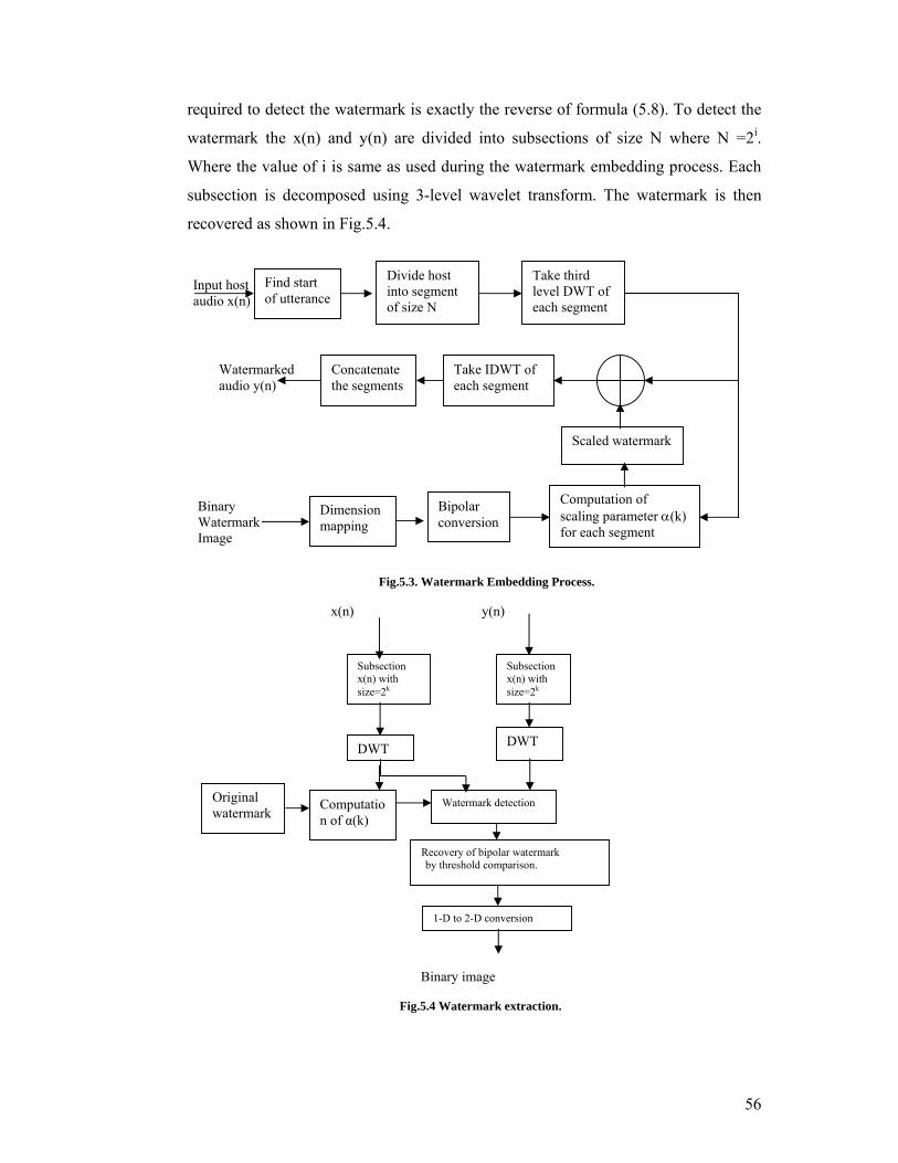
The watermark embedding process is shown in Fig 5.3. The host audio signal
x(n) is divided into subsections of size N=2i, each subsection is decomposed into 3-
level Discrete wavelet transform by means of Harr wavelet transform. The Haar
wavelet is used in the implementation because Haar wavelet gives perfect
reconstructability which is essential feature for this application. The authors in [29]
used db4 wavelet as for Daubechieves wavelets compact signal property is not
maintained if we increase the number of points in the wavelet, as well as its
reconstructability is not mentioned. So we used Haar wavelet in our implementation.
The detailed coefficients (cd3) of host audio signal are selected for embedding the
watermark in low frequency part of highest energy of audio signal.
The M1 × M2 binary image is considered as a watermark. Before embedding
this 2-D watermark into host audio it is converted into its 1-D bipolar equivalent w(k)
{1,-1}. Then w(k) is scaled by the parameter α(k) and One bit of w(k) is embedded
into a single subsection of host audio signal.
To find the imperceptibility of the system SNR between the host audio signal
and watermarked signal is computed by the formula (5.7). It is observed that the SNR
obtained using this technique is 43.77 db. The watermarked signal and host audio
signal is played in front of the ten personalities having the knowledge of music. It is
observed by the all five personalities that there is no perceptual difference between
the host audio signal and the watermarked audio signal.
In order to proceed to detect the watermark the knowledge of scaling
parameter α is very important without the knowledge of α(k) it is not possible to
detect the watermark. Scaling parameter α(k) is computed during the watermark
embedding process using the formula (5.10). The original signal x(n) is required to
compute the value of α(k) in order to recover the watermark properly. The formula
56
required to detect the watermark is exactly the reverse of formula (5.8). To detect the
watermark the x(n) and y(n) are divided into subsections of size N where N =2i.
Where the value of i is same as used during the watermark embedding process. Each
subsection is decomposed using 3-level wavelet transform. The watermark is then
recovered as shown in Fig.5.4.
Fig.5.3. Watermark Embedding Process.
x(n) y(n) α Binary image
Fig.5.4 Watermark extraction.
Watermarked audio y(n)
Input host audio x(n)
Binary Watermark Image
Subsection x(n) with size=2k
Subsection x(n) with size=2k
DWT DWT
Watermark detection
Recovery of bipolar watermark by threshold comparison.
1-D to 2-D conversion
Find start of utterance
Divide host into segment of size N
Take third level DWT of each segment
Dimension mapping
Bipolar conversion
Computation of scaling parameter α(k) for each segment
Scaled watermark
Take IDWT of each segment
Concatenate the segments
Original watermark Computatio
n of α(k)
57
After detecting the presence of watermark each value is compared against the
threshold value T to recover the bipolar watermark. If the value of the sample is
greater than the threshold then watermark bit is recovered as 1 otherwise if value of
sample is less than threshold the watermark bit is recovered as 0.The recovered
watermark is 1-D signal so it is converted into the required 2-D form of size M1× M2
to recover the binary image used as watermark. In order to test the similarity between
the recovered watermark and the original watermark the correlation coefficient
between original watermark and recovered watermark is computed.
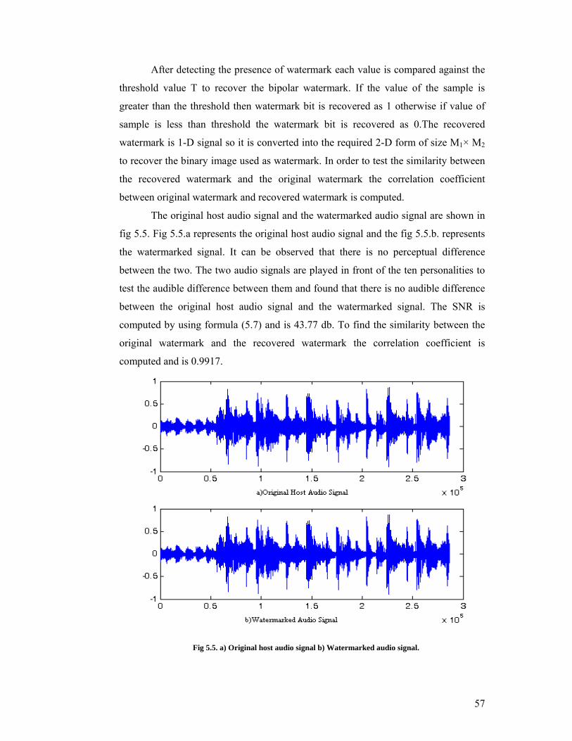
The original host audio signal and the watermarked audio signal are shown in
fig 5.5. Fig 5.5.a represents the original host audio signal and the fig 5.5.b. represents
the watermarked signal. It can be observed that there is no perceptual difference
between the two. The two audio signals are played in front of the ten personalities to
test the audible difference between them and found that there is no audible difference
between the original host audio signal and the watermarked signal. The SNR is
computed by using formula (5.7) and is 43.77 db. To find the similarity between the
original watermark and the recovered watermark the correlation coefficient is
computed and is 0.9917.
Fig 5.5. a) Original host audio signal b) Watermarked audio signal.
58
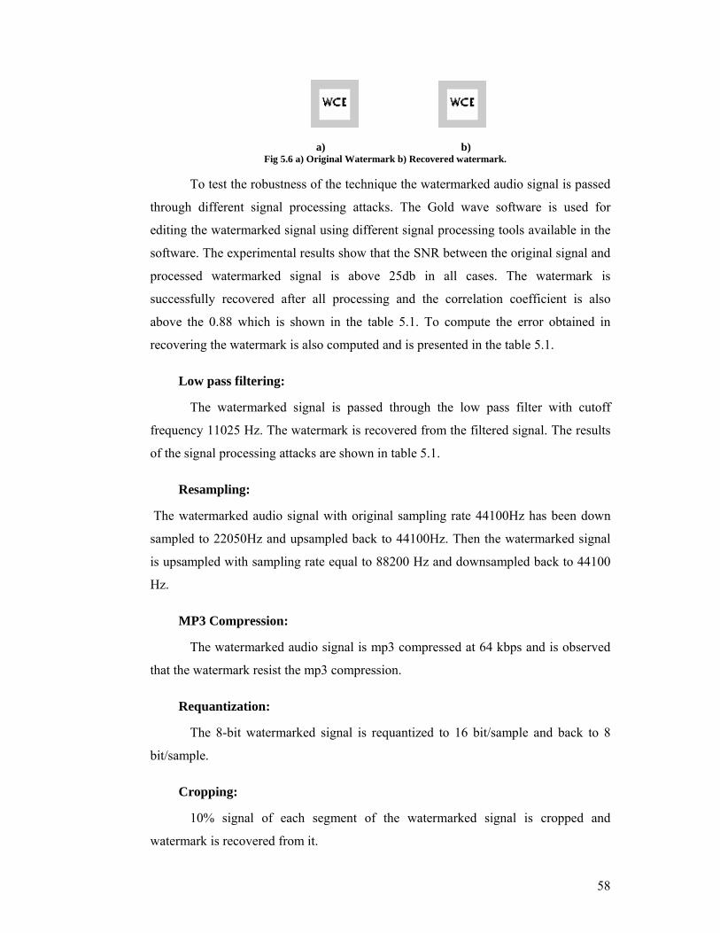
a) b) Fig 5.6 a) Original Watermark b) Recovered watermark.
To test the robustness of the technique the watermarked audio signal is passed
through different signal processing attacks. The Gold wave software is used for
editing the watermarked signal using different signal processing tools available in the
software. The experimental results show that the SNR between the original signal and
processed watermarked signal is above 25db in all cases. The watermark is
successfully recovered after all processing and the correlation coefficient is also
above the 0.88 which is shown in the table 5.1. To compute the error obtained in
recovering the watermark is also computed and is presented in the table 5.1.
Low pass filtering:
The watermarked signal is passed through the low pass filter with cutoff
frequency 11025 Hz. The watermark is recovered from the filtered signal. The results
of the signal processing attacks are shown in table 5.1.
Resampling:
The watermarked audio signal with original sampling rate 44100Hz has been down
sampled to 22050Hz and upsampled back to 44100Hz. Then the watermarked signal
is upsampled with sampling rate equal to 88200 Hz and downsampled back to 44100
Hz.
MP3 Compression:
The watermarked audio signal is mp3 compressed at 64 kbps and is observed
that the watermark resist the mp3 compression.
Requantization:
The 8-bit watermarked signal is requantized to 16 bit/sample and back to 8
bit/sample.
Cropping:
10% signal of each segment of the watermarked signal is cropped and
watermark is recovered from it.
59
Noise addition:
White noise with 15 of the power audio signal is added into the watermarked
audio signal.
Echo addition:
Echo signal of a delay of 100ms and a volume control of 50% is added to the
original audio signal.
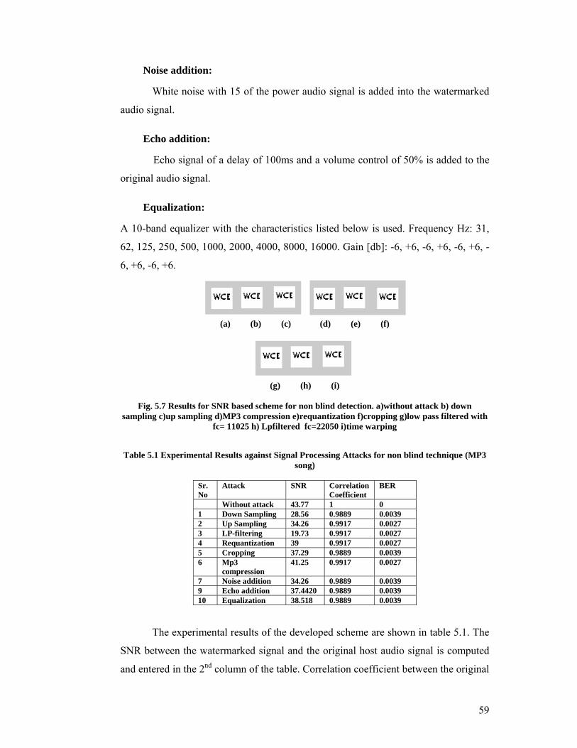
Equalization:
A 10-band equalizer with the characteristics listed below is used. Frequency Hz: 31,
62, 125, 250, 500, 1000, 2000, 4000, 8000, 16000. Gain [db]: -6, +6, -6, +6, -6, +6, -
6, +6, -6, +6.
(a) (b) (c) (d) (e) (f)
(g) (h) (i)
Fig. 5.7 Results for SNR based scheme for non blind detection. a)without attack b) down
sampling c)up sampling d)MP3 compression e)requantization f)cropping g)low pass filtered with fc= 11025 h) Lpfiltered fc=22050 i)time warping
Table 5.1 Experimental Results against Signal Processing Attacks for non blind technique (MP3
song)
Sr. No
Attack SNR Correlation Coefficient
BER
Without attack 43.77 1 0 1 Down Sampling 28.56 0.9889 0.0039 2 Up Sampling 34.26 0.9917 0.0027 3 LP-filtering 19.73 0.9917 0.0027 4 Requantization 39 0.9917 0.0027 5 Cropping 37.29 0.9889 0.0039 6 Mp3
compression 41.25 0.9917 0.0027
7 Noise addition 34.26 0.9889 0.0039 9 Echo addition 37.4420 0.9889 0.0039 10 Equalization 38.518 0.9889 0.0039
The experimental results of the developed scheme are shown in table 5.1. The
SNR between the watermarked signal and the original host audio signal is computed
and entered in the 2nd column of the table. Correlation coefficient between the original
60
watermark and the recovered watermark is entered in the 3rd column of the table. The
BER between the original watermark and the recovered watermark is entered in the
4th column of the table. The experimental results show that the developed technique
recovers the watermark successfully after all kinds of signal processing attacks
mentioned in the table. It is observed that the SNR between the original signal and the
distorted signal is within the acceptable limit of 20db and is above this limit except
for the LP-filtering and down sampling.
The major draw back of this scheme is that it requires the original host signal
and the original watermark signal in order to recover the watermark and to provide the
proof of ownership. To overcome these drawbacks we modified this scheme and
proposed the SNR based blind watermarking scheme.
5.3. Proposed adaptive SNR based blind watermarking using
DWT /Lifting wavelet transform:
This section highlights on the proposed adaptive SNR based blind
watermarking scheme implemented in DWT and LWT domain. In this scheme we
have made an attempt to recover the watermark signal without the help of original
audio signal. We are also successful in recovering the watermark without using the
scaling parameter. The scaling parameter used to embed the watermark is varied
adaptively for each segment in order to achieve the imperceptibility and to take the
advantage of insensitivity of HAS to smaller variations in transform domain. To
provide the security to the system the secret key is used and the secret key is a PNR
sequence generated by any cryptographic method. Without the knowledge of this
secret key it is not possible to recover the watermark hence it is required to generate
with secret initial seed. This idea of generating the pseudo random number from
initial seed is borrowed from communications.
Our aim in developing this scheme is to devise a system which embeds the
watermark using spread spectrum method and does not require the original audio
signal to recover the embedded watermark. The embedding process modifies the host
signal x by mixing function f(.). f(x, w) performs the mixing of x (host multimedia
signal) and w(watermark signal) with the help of secrete key k. In most of the
watermarking technique [12, 19] mixing function is the addition of original host
signal and scaled watermark signal mathematically represented by formula (5.1). The
61
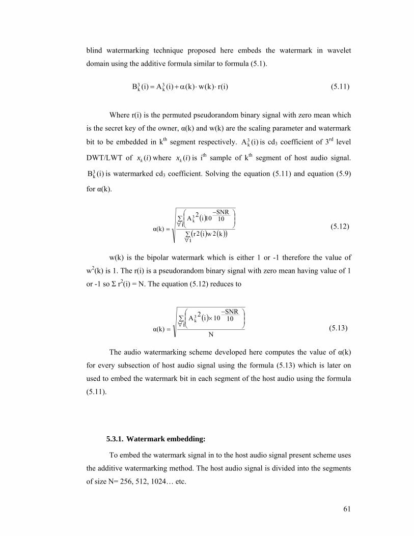
blind watermarking technique proposed here embeds the watermark in wavelet
domain using the additive formula similar to formula (5.1).
)i(r)k(w)k()i(A)i(B 3
k3k ⋅⋅α+= (5.11)
Where r(i) is the permuted pseudorandom binary signal with zero mean which
is the secret key of the owner, α(k) and w(k) are the scaling parameter and watermark
bit to be embedded in kth segment respectively. )i(A3k is cd3 coefficient of 3rd level
DWT/LWT of )(ixk where )(ixk is ith sample of kth segment of host audio signal.
)i(B3k is watermarked cd3 coefficient. Solving the equation (5.11) and equation (5.9)
for α(k).
( )
( ) ( )( )∑∀
∑∀ ⎟
⎟⎠
⎞⎜⎜⎝
⎛ −
=
ik2wi2r
i10SNR
10i2Aα(k)
3k
(5.12)
w(k) is the bipolar watermark which is either 1 or -1 therefore the value of
w2(k) is 1. The r(i) is a pseudorandom binary signal with zero mean having value of 1
or -1 so Σ r2(i) = N. The equation (5.12) reduces to
( )
Ni
10SNR
10 i2Aα(k)
3k∑
∀ ⎟⎟⎠
⎞⎜⎜⎝
⎛ −×
= (5.13)
The audio watermarking scheme developed here computes the value of α(k)
for every subsection of host audio signal using the formula (5.13) which is later on
used to embed the watermark bit in each segment of the host audio using the formula
(5.11).
5.3.1. Watermark embedding:
To embed the watermark signal in to the host audio signal present scheme uses
the additive watermarking method. The host audio signal is divided into the segments
of size N= 256, 512, 1024… etc.
62
Xk(i) = X (k . N + i) i=0,1,2…..N-1, K=0,1,2….. (5.14)
N=256, 1024
Where X(i) represent the original host audio signal and Xk(i) represent the kth
segment of the host audio. Then each Xk(i) is decomposed to Lth level wavelet
transform. The scheme is implemented using Discrete Wavelet Transform (DWT) and
Lifting Wavelet transform (LWT). To embed the watermark into low frequency part
of the highest energy of audio signal by taking advantage of frequency mask effect of
HAS [29] the 3rd level detail part of coefficients is selected. After selecting the
watermark embedding formula the 3rd approximate coefficients are modified as
i)α(k)w(k)r((i)A(i)A 3
k3k += (5.15)
Where (i)A3
k are 3rd level approximate coefficients. Where r(i) is the permuted
pseudorandom binary signal with zero mean which is the secret key of the owner, α(k)
and w(k) are the scaling parameter and watermark bit to be embedded in kth segment
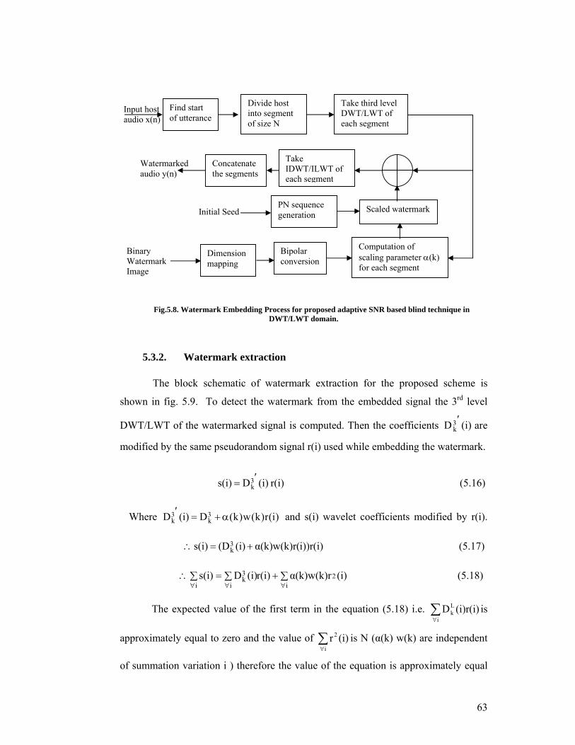
respectively. The block schematic of the proposed scheme is shown in the fig. 5.8.
The SNR between the original signal and the watermarked signal can be computed by
using formula (5.7) to measure the imperceptibility of the watermarked signal.
In this method we compute the scaling parameter α(k) for every segment of
host audio signal and then embed according to the rules for bit one or bit 0 of
watermark signal. This variation of α(k) for every segment takes in to account the
feature of the host audio in that segment and then compute the value of α(k), which is
similar to finding the scaling parameter taking into consideration the perceptual
transparency of the host audio.
63
Fig.5.8. Watermark Embedding Process for proposed adaptive SNR based blind technique in DWT/LWT domain.
5.3.2. Watermark extraction
The block schematic of watermark extraction for the proposed scheme is
shown in fig. 5.9. To detect the watermark from the embedded signal the 3rd level
DWT/LWT of the watermarked signal is computed. Then the coefficients (i)D3k′ are
modified by the same pseudorandom signal r(i) used while embedding the watermark.
r(i) (i)Ds(i) 3k′= (5.16)
Where )i(r)k(w)k(D(i)D 3k
3k α+=′ and s(i) wavelet coefficients modified by r(i).
i))r(i)α(k)w(k)r((i)(Ds(i) 3
k +=∴ (5.17) ∑+∑=∑∴
∀∀∀ i2
i
3k
i(i)α(k)w(k)rr(i)(i)Ds(i) (5.18)
The expected value of the first term in the equation (5.18) i.e. ∑
∀i
Lk (i)r(i)D is
approximately equal to zero and the value of ∑∀i
2 (i)r is N (α(k) w(k) are independent
of summation variation i ) therefore the value of the equation is approximately equal
Initial Seed
Watermarked audio y(n)
Input host audio x(n)
Binary Watermark Image
Find start of utterance
Divide host into segment of size N
Dimension mapping
Bipolar conversion
Computation of scaling parameter α(k) for each segment
Scaled watermark
Concatenate the segments
PN sequence generation
Take third level DWT/LWT of each segment
Take IDWT/ILWT of each segment
64
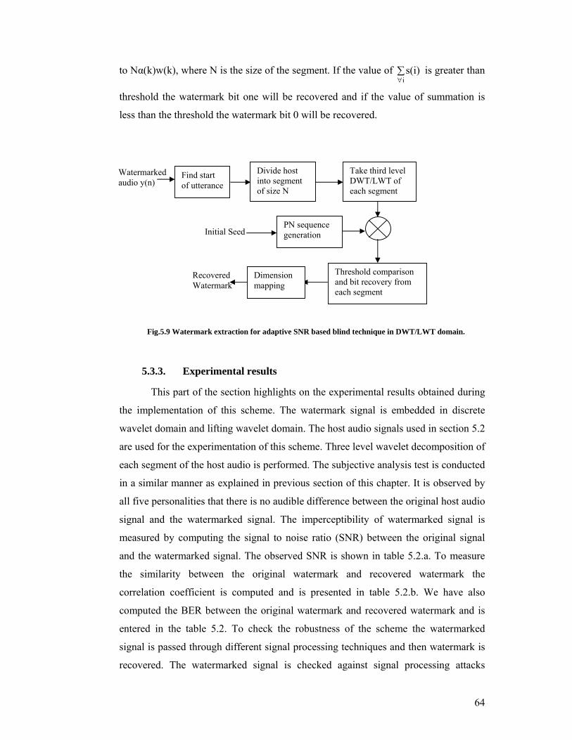
to Nα(k)w(k), where N is the size of the segment. If the value of ∑∀i
s(i) is greater than
threshold the watermark bit one will be recovered and if the value of summation is
less than the threshold the watermark bit 0 will be recovered.
Fig.5.9 Watermark extraction for adaptive SNR based blind technique in DWT/LWT domain.
5.3.3. Experimental results
This part of the section highlights on the experimental results obtained during
the implementation of this scheme. The watermark signal is embedded in discrete
wavelet domain and lifting wavelet domain. The host audio signals used in section 5.2
are used for the experimentation of this scheme. Three level wavelet decomposition of
each segment of the host audio is performed. The subjective analysis test is conducted
in a similar manner as explained in previous section of this chapter. It is observed by
all five personalities that there is no audible difference between the original host audio
signal and the watermarked signal. The imperceptibility of watermarked signal is
measured by computing the signal to noise ratio (SNR) between the original signal
and the watermarked signal. The observed SNR is shown in table 5.2.a. To measure
the similarity between the original watermark and recovered watermark the
correlation coefficient is computed and is presented in table 5.2.b. We have also
computed the BER between the original watermark and recovered watermark and is
entered in the table 5.2. To check the robustness of the scheme the watermarked
signal is passed through different signal processing techniques and then watermark is
recovered. The watermarked signal is checked against signal processing attacks
Recovered Watermark
Watermarked audio y(n)
Find start of utterance
Divide host into segment of size N
Take third level DWT/LWT of each segment
Initial Seed PN sequence generation
Threshold comparison and bit recovery from each segment
Dimension mapping
65
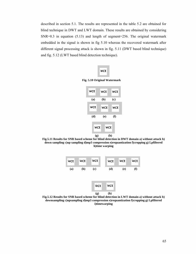
described in section 5.1. The results are represented in the table 5.2 are obtained for
blind technique in DWT and LWT domain. These results are obtained by considering
SNR=0.3 in equation (5.13) and length of segment=256. The original watermark
embedded in the signal is shown in fig 5.10 whereas the recovered watermark after
different signal processing attack is shown in fig. 5.11 (DWT based blind technique)
and fig. 5.12 (LWT based blind detection technique).
(a) (b) (c)
(d) (e) (f)
(g) (h)
Fig.5.11 Results for SNR based scheme for blind detection in DWT domain a) without attack b) down sampling c)up sampling d)mp3 compression e)requantization f)cropping g) Lpfiltered
h)time warping
(a) (b) (c) (d) (e) (f)
(g) (h)
Fig.5.12 Results for SNR based scheme for blind detection in LWT domain a) without attack b) downsampling c)upsampling d)mp3 compression e)requantization f)cropping g) Lpfiltered
i)timewarping
Fig. 5.10 Original Watermark
66
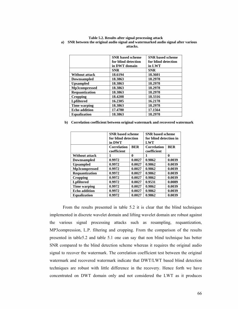
Table 5.2. Results after signal processing attack a) SNR between the original audio signal and watermarked audio signal after various
attacks.
b) Correlation coefficient between original watermark and recovered watermark
From the results presented in table 5.2 it is clear that the blind techniques
implemented in discrete wavelet domain and lifting wavelet domain are robust against
the various signal processing attacks such as resampling, requantization,
MP3compression, L.P. filtering and cropping. From the comparison of the results
presented in table5.2 and table 5.1 one can say that non blind technique has better
SNR compared to the blind detection scheme whereas it requires the original audio
signal to recover the watermark. The correlation coefficient test between the original
watermark and recovered watermark indicate that DWT/LWT based blind detection
techniques are robust with little difference in the recovery. Hence forth we have
concentrated on DWT domain only and not considered the LWT as it produces
SNR based scheme for blind detection in DWT domain
SNR based scheme for blind detection in LWT
SNR SNR Without attack 18.6194 18.3601 Downsampled 18.3863 18.2978 Upsampled 18.3863 18.2978 Mp3compressed 18.3863 18.2978Requantization 18.3863 18.2978 Cropping 18.4208 18.3316 Lpfiltered 16.2305 16.2178 Time warping 18.3863 18.2978 Echo addition 17.4780 17.1564 Equalization 18.3863 18.2978
SNR based scheme for blind detection in DWT
SNR based scheme for blind detection in LWT
Correlationcoefficient
BER Correlation coefficient
BER
Without attack 1 0 1 0 Downsampled 0.9972 0.0027 0.9862 0.0039 Upsampled 0.9972 0.0027 0.9862 0.0039 Mp3compressed 0.9972 0.0027 0.9862 0.0039 Requantization 0.9972 0.0027 0.9862 0.0039 Cropping 0.9972 0.0027 0.9862 0.0039 Lpfiltered 0.9972 0.0027 0.9531 0.0089 Time warping 0.9972 0.0027 0.9862 0.0039 Echo addition 0.9972 0.0027 0.9862 0.0039 Equalization 0.9972 0.0027 0.9862 0.0039
67
similar results. The observed SNR between the original host signal and the
watermarked signal even after signal processing attacks is less than 20 during the
experimentation results obtained in table 5.2. This is because of the parameter α(k)
calculated from (5.13) by considering SNR=30 the lowest threshold requirement. As
explained in the next subsection these imperceptibility results can be improved with
increase in SNR consideration while computing α(k).
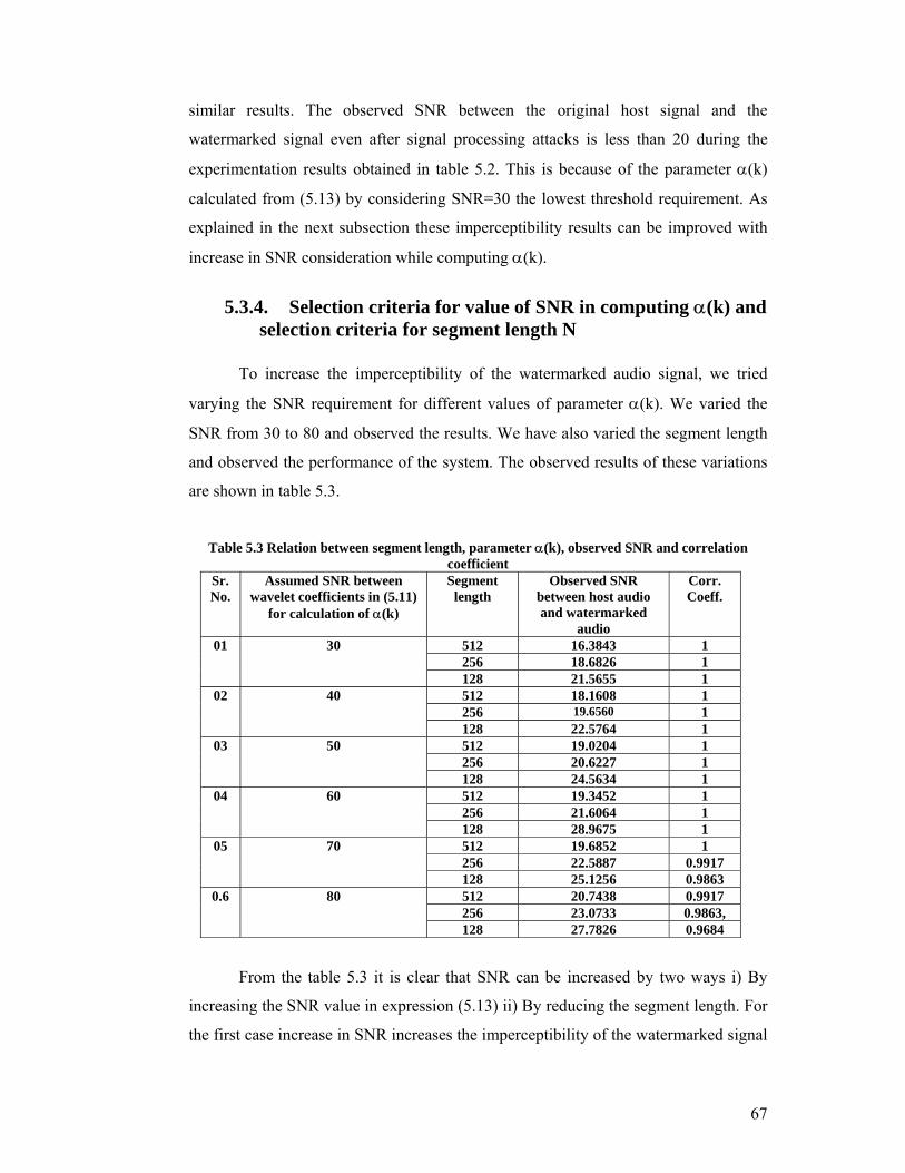
5.3.4. Selection criteria for value of SNR in computing α(k) and selection criteria for segment length N
To increase the imperceptibility of the watermarked audio signal, we tried
varying the SNR requirement for different values of parameter α(k). We varied the
SNR from 30 to 80 and observed the results. We have also varied the segment length
and observed the performance of the system. The observed results of these variations
are shown in table 5.3.
Table 5.3 Relation between segment length, parameter α(k), observed SNR and correlation
coefficient Sr.No.
Assumed SNR between wavelet coefficients in (5.11)
for calculation of α(k)
Segment length
Observed SNR between host audio and watermarked
audio
Corr. Coeff.
01 30 512 16.3843 1 256 18.6826 1 128 21.5655 1
02 40 512 18.1608 1 256 19.6560 1 128 22.5764 1
03 50 512 19.0204 1 256 20.6227 1 128 24.5634 1
04 60 512 19.3452 1 256 21.6064 1 128 28.9675 1
05 70 512 19.6852 1 256 22.5887 0.9917 128 25.1256 0.9863
0.6 80 512 20.7438 0.9917 256 23.0733 0.9863, 128 27.7826 0.9684
From the table 5.3 it is clear that SNR can be increased by two ways i) By
increasing the SNR value in expression (5.13) ii) By reducing the segment length. For
the first case increase in SNR increases the imperceptibility of the watermarked signal
68
whereas reduces the robustness. For the second case i.e reduction in segment length
improves the SNR but reduce the robustness. The optimized results can be obtained
considering all the contradictory requirements of watermarking by selecting segment
length 256 and SNR in the range 40 – 60. Therefore while obtaining the comparison
results of implementations of spread spectrum watermarking the SNR is selected as
60 and segment length is considered as 256.
5.4. Proposed Adaptive SNR based spread spectrum scheme in
DWT-DCT domain:
This section highlights on the proposed SNR based spread spectrum technique
of audio watermarking which adaptively select the embedding strength to embed the
watermark. This scheme embeds the watermark by first taking the 3rd level DWT of
the host audio signal and then computing the DCT of the low pass filtered DWT
coefficients. DWT-DCT transform is used to embed the watermark in low-middle
frequency components of host audio in order to increase the imperceptibility of the
watermarking scheme as compared to the scheme implemented in previous section.
Using DCT of the Ca3 coefficients, we can exactly track the required frequency band
to embed the watermark for better imperceptibility. The spread spectrum
watermarking techniques [2, 3, 9] modifies the host multimedia signal using the
mathematical function defined by (5.1)
The scheme proposed here first divide the host audio signal into smaller
segments of size N. Then it computes 3 rd level DWT of each segment. Then the ca3
(Low pass filtered coefficients) coefficients are selected for embedding the watermark
and take the DCT coefficients of ca3 (3rd level DWT coefficients of host audio)
coefficients to add the watermark bit using the formula (5.19) described below.
)k(w)i(r)k()i(A)i(A 3k
3k ⋅⋅α+=′ (5.19)
where r(i) is the permuted pseudorandom binary signal of length L with zero
mean which is the secret key of the owner. The length L is equal to the length of the
3rd level DWT-DCT coefficients. α(k) is the adaptive scaling parameter computed for
kth segment in which watermark is required to be added and w(k) the watermark bit to
be embedded in kth segment. )i(A3k′ is the DWT-DCT coefficient of the watermarked
signal for kth segment and )i(A3k is the DWT-DCT coefficient of the original host
69
signal for kth segment. Solving the equation (5.19) and equation (5.9) for α(k).
( )
( ) ( )( )∑∀
⎟⎠⎞
⎜⎝⎛∑
=α
−
∀
ikwir
10)i(A)k( 22
)10/SNR(
i
23k
(5.20)
w(k) is the bipolar watermark which is either 1 or -1 therefore the value of
w2(k) is 1. The r(i) is a pseudorandom binary signal with zero mean with value of 1 or
-1 so Σ r2(i) = L. The equation (5.13) reduces to
L
10)i(A)k(
)10/SNR(
i
23k
−
∀⎟⎠⎞
⎜⎝⎛∑
=α (5.21)
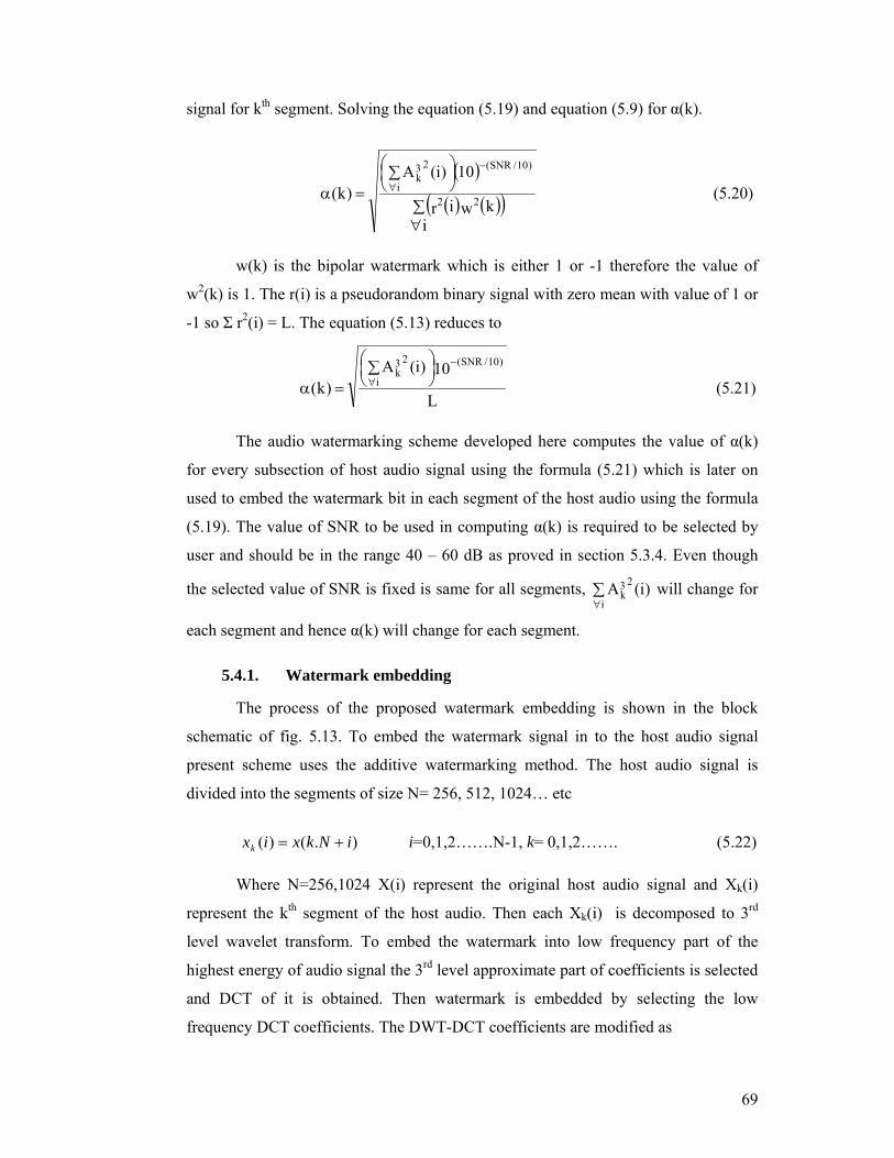
The audio watermarking scheme developed here computes the value of α(k)
for every subsection of host audio signal using the formula (5.21) which is later on
used to embed the watermark bit in each segment of the host audio using the formula
(5.19). The value of SNR to be used in computing α(k) is required to be selected by
user and should be in the range 40 – 60 dB as proved in section 5.3.4. Even though
the selected value of SNR is fixed is same for all segments, ∑∀i
23k )i(A will change for
each segment and hence α(k) will change for each segment.
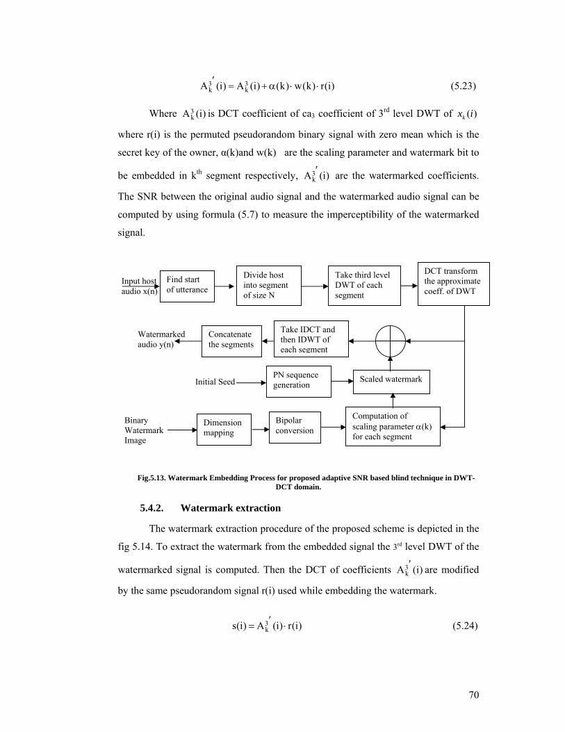
5.4.1. Watermark embedding
The process of the proposed watermark embedding is shown in the block
schematic of fig. 5.13. To embed the watermark signal in to the host audio signal
present scheme uses the additive watermarking method. The host audio signal is
divided into the segments of size N= 256, 512, 1024… etc
).()( iNkxixk += i=0,1,2…….N-1, k= 0,1,2……. (5.22) Where N=256,1024 X(i) represent the original host audio signal and Xk(i)
represent the kth segment of the host audio. Then each Xk(i) is decomposed to 3rd
level wavelet transform. To embed the watermark into low frequency part of the
highest energy of audio signal the 3rd level approximate part of coefficients is selected
and DCT of it is obtained. Then watermark is embedded by selecting the low
frequency DCT coefficients. The DWT-DCT coefficients are modified as
70
)i(r)k(w)k()i(A)i(A 3k
3k ⋅⋅α+=′ (5.23)
Where )i(A3
k is DCT coefficient of ca3 coefficient of 3rd level DWT of )(ixk
where r(i) is the permuted pseudorandom binary signal with zero mean which is the
secret key of the owner, α(k)and w(k) are the scaling parameter and watermark bit to
be embedded in kth segment respectively, )i(A3k′ are the watermarked coefficients.
The SNR between the original audio signal and the watermarked audio signal can be
computed by using formula (5.7) to measure the imperceptibility of the watermarked
signal.
Fig.5.13. Watermark Embedding Process for proposed adaptive SNR based blind technique in DWT-DCT domain.
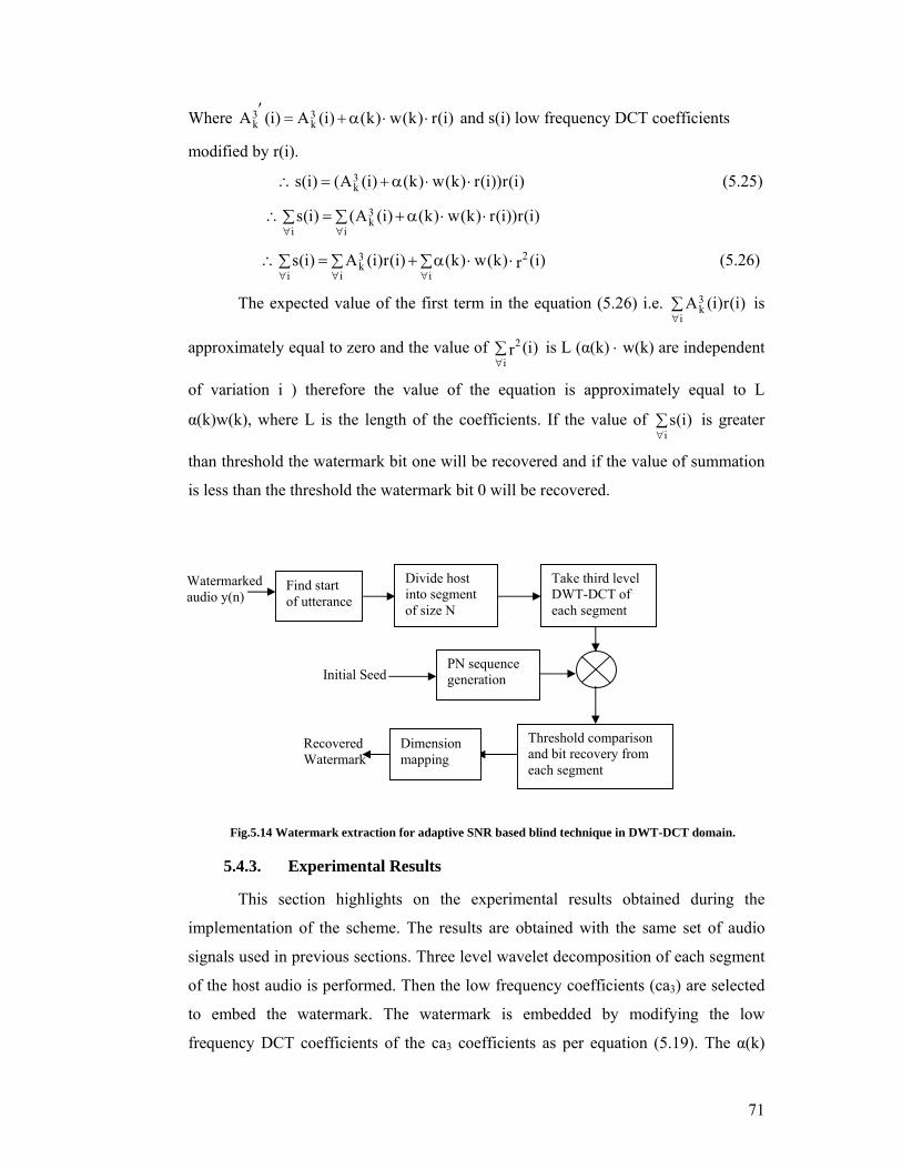
5.4.2. Watermark extraction
The watermark extraction procedure of the proposed scheme is depicted in the
fig 5.14. To extract the watermark from the embedded signal the 3rd level DWT of the
watermarked signal is computed. Then the DCT of coefficients )i(A3k′ are modified
by the same pseudorandom signal r(i) used while embedding the watermark.
)i(r)i(A)i(s 3k ⋅′= (5.24)
Initial Seed
Watermarked audio y(n)
Input host audio x(n)
Binary Watermark Image
Find start of utterance
Divide host into segment of size N
Dimension mapping
Bipolar conversion
Computation of scaling parameter α(k) for each segment
Scaled watermark
Concatenate the segments
PN sequence generation
Take third level DWT of each segment
Take IDCT and then IDWT of each segment
DCT transform the approximate coeff. of DWT
71
Where )i(r)k(w)k()i(A)i(A 3k
3k ⋅⋅α+=′ and s(i) low frequency DCT coefficients
modified by r(i).
)i(r))i(r)k(w)k()i(A()i(s 3k ⋅⋅α+=∴ (5.25)
∑ ⋅⋅α+=∑∴∀∀ i
3k
i)i(r))i(r)k(w)k()i(A()i(s
∑ ∑ ⋅⋅α+=∑∴∀ ∀∀ i i
23k
i)i(r)k(w)k()i(r)i(A)i(s (5.26)
The expected value of the first term in the equation (5.26) i.e. ∑∀i
3k )i(r)i(A is
approximately equal to zero and the value of ∑∀i
2 )i(r is L (α(k) ⋅ w(k) are independent
of variation i ) therefore the value of the equation is approximately equal to L
α(k)w(k), where L is the length of the coefficients. If the value of ∑∀i
)i(s is greater
than threshold the watermark bit one will be recovered and if the value of summation
is less than the threshold the watermark bit 0 will be recovered.
Fig.5.14 Watermark extraction for adaptive SNR based blind technique in DWT-DCT domain.
5.4.3. Experimental Results
This section highlights on the experimental results obtained during the
implementation of the scheme. The results are obtained with the same set of audio
signals used in previous sections. Three level wavelet decomposition of each segment
of the host audio is performed. Then the low frequency coefficients (ca3) are selected
to embed the watermark. The watermark is embedded by modifying the low
frequency DCT coefficients of the ca3 coefficients as per equation (5.19). The α(k)
Recovered Watermark
Watermarked audio y(n)
Find start of utterance
Divide host into segment of size N
Take third level DWT-DCT of each segment
Initial Seed PN sequence generation
Threshold comparison and bit recovery from each segment
Dimension mapping
72
used in the equation (5.19) to add the watermark bit w(k) is computed using
equation(5.21) and the value of SNR considered in the equation(5.21) is 30 dB to
obtain the results for minimum threshold.
The subjective analysis test proved that there is no perceptible difference
between the host audio and watermarked audio. The signal to noise ratio (SNR)
between the host audio signal and watermarked audio signal is computed using
equation (5.9) and is shown in table 5.4. The BER between the original watermark
and recovered watermark is computed and is presented in table 5.4.
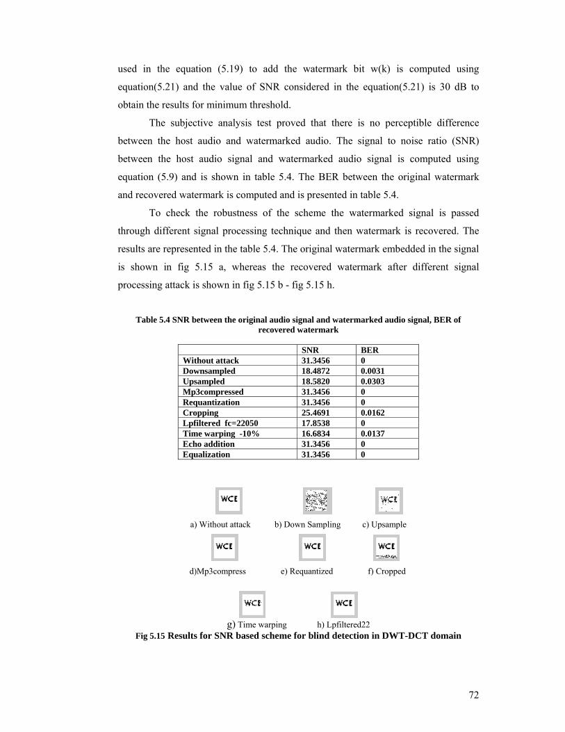
To check the robustness of the scheme the watermarked signal is passed
through different signal processing technique and then watermark is recovered. The
results are represented in the table 5.4. The original watermark embedded in the signal
is shown in fig 5.15 a, whereas the recovered watermark after different signal
processing attack is shown in fig 5.15 b - fig 5.15 h.
Table 5.4 SNR between the original audio signal and watermarked audio signal, BER of
recovered watermark
a) Without attack b) Down Sampling c) Upsample
d)Mp3compress e) Requantized f) Cropped
g) Time warping h) Lpfiltered22
Fig 5.15 Results for SNR based scheme for blind detection in DWT-DCT domain
SNR BER Without attack 31.3456 0 Downsampled 18.4872 0.0031 Upsampled 18.5820 0.0303 Mp3compressed 31.3456 0 Requantization 31.3456 0Cropping 25.4691 0.0162 Lpfiltered fc=22050 17.8538 0 Time warping -10% 16.6834 0.0137 Echo addition 31.3456 0 Equalization 31.3456 0
73
From the results presented in table 5.4 it is clear that the technique
implemented here is robust against the various signal processing attacks such as
resampling, requantization, mp3compression and cropping. It is also observed that the
technique is robust against LP filtering with cutoff frequency of 22 KHz. From the
results presented in table 5.4 it is clear that SNR between the original audio and
watermarked audio after different signal processing attacks satisfies the audio
watermarking requirements provided by IFPI [28]. The BER (bit error rate) test
between the original watermark and recovered watermark indicate that the technique
is able to recover the watermark after different signal processing attacks.
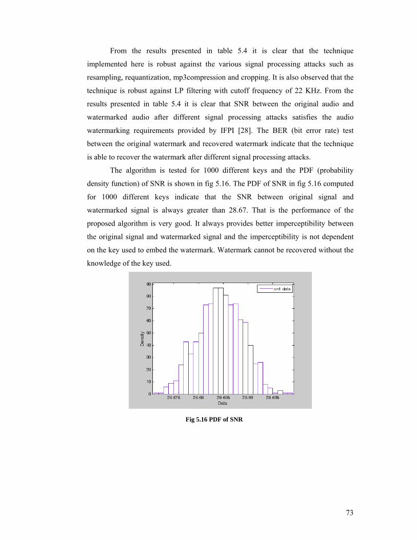
The algorithm is tested for 1000 different keys and the PDF (probability
density function) of SNR is shown in fig 5.16. The PDF of SNR in fig 5.16 computed
for 1000 different keys indicate that the SNR between original signal and
watermarked signal is always greater than 28.67. That is the performance of the
proposed algorithm is very good. It always provides better imperceptibility between
the original signal and watermarked signal and the imperceptibility is not dependent
on the key used to embed the watermark. Watermark cannot be recovered without the
knowledge of the key used.
Fig 5.16 PDF of SNR
74
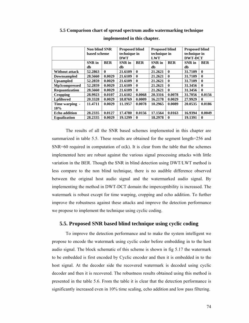
5.5 Comparison chart of spread spectrum audio watermarking technique
implemented in this chapter.
The results of all the SNR based schemes implemented in this chapter are
summarized in table 5.5. These results are obtained for the segment length=256 and
SNR=60 required in computation of α(k). It is clear from the table that the schemes
implemented here are robust against the various signal processing attacks with little
variation in the BER. Though the SNR in blind detection using DWT/LWT method is
less compare to the non blind technique, there is no audible difference observed
between the original host audio signal and the watermarked audio signal. By
implementing the method in DWT-DCT domain the imperceptibility is increased. The
watermark is robust except for time warping, cropping and echo addition. To further
improve the robustness against these attacks and improve the detection performance
we propose to implement the technique using cyclic coding.
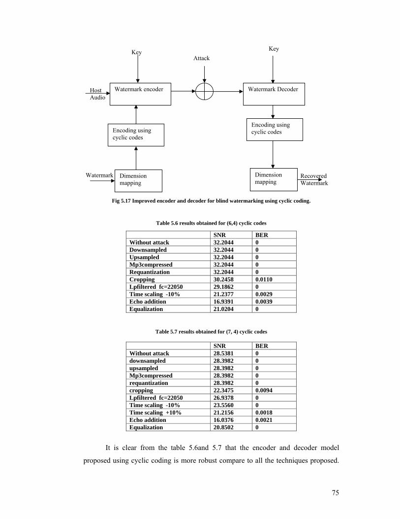
5.5. Proposed SNR based blind technique using cyclic coding
To improve the detection performance and to make the system intelligent we
propose to encode the watermark using cyclic coder before embedding in to the host
audio signal. The block schematic of this scheme is shown in fig 5.17 the watermark
to be embedded is first encoded by Cyclic encoder and then it is embedded in to the
host signal. At the decoder side the recovered watermark is decoded using cyclic
decoder and then it is recovered. The robustness results obtained using this method is
presented in the table 5.6. From the table it is clear that the detection performance is
significantly increased even in 10% time scaling, echo addition and low pass filtering.
Non blind SNR based scheme
Proposed blind technique in DWT
Proposed blind technique in LWT
Proposed blind technique in DWT-DCT
SNR in db
BER SNR in db
BER SNR in db
BER SNR in db
BER
Without attack 52.2863 0 21.6109 0 21.2621 0 31.7109 0 Downsampled 28.5660 0.0029 21.6109 0 21.2621 0 31.7109 0 Upsampled 52.2859 0.0029 21.6109 0 21.2621 0 31.7109 0 Mp3compressed 52.2859 0.0029 21.6109 0 21.2621 0 31.3456 0 Requantization 28.5660 0.0029 21.6109 0 21.2621 0 31.3456 0 Cropping 28.9923 0.0107 21.6102 0.0068 20.3316 0.0078 31.7056 0.0156 Lpfiltered 20.3328 0.0029 18.8769 0.0009 16.2178 0.0029 27.9929 0 Time warping -10%
11.4711 0.0029 11.1957 0.0078 10.2965 0.0089 20.0535 0.0186
Echo addition 28.2335 0.0127 17.4780 0.0156 17.1564 0.0163 16.9394 0.0049 Equalization 28.2335 0.0029 19.1299 0 18.2978 0 19.1391 0
75
Fig 5.17 Improved encoder and decoder for blind watermarking using cyclic coding.
Table 5.6 results obtained for (6,4) cyclic codes
Table 5.7 results obtained for (7, 4) cyclic codes
It is clear from the table 5.6and 5.7 that the encoder and decoder model
proposed using cyclic coding is more robust compare to all the techniques proposed.
SNR BER Without attack 32.2044 0 Downsampled 32.2044 0 Upsampled 32.2044 0 Mp3compressed 32.2044 0 Requantization 32.2044 0 Cropping 30.2458 0.0110 Lpfiltered fc=22050 29.1862 0 Time scaling -10% 21.2377 0.0029 Echo addition 16.9391 0.0039 Equalization 21.0204 0
SNR BER Without attack 28.5381 0 downsampled 28.3982 0 upsampled 28.3982 0 Mp3compressed 28.3982 0 requantization 28.3982 0 cropping 22.3475 0.0094 Lpfiltered fc=22050 26.9378 0 Time scaling -10% 23.5560 0 Time scaling +10% 21.2156 0.0018 Echo addition 16.0376 0.0021 Equalization 20.8502 0
Key Key Attack
Recovered Watermark
Host Audio
Watermark encoder
Watermark
Encoding using cyclic codes
Dimension mapping
Dimension mapping
Watermark Decoder
Encoding using cyclic codes
76
With small sacrifice in imperceptibility test the (7, 4) cyclic coder provides the best
robustness test as our main aim is to embed the watermark which sustain all kinds of
attacks and recover the watermark successfully.
5.6. Summary of chapter:
Adaptive SNR based schemes are proposed in this chapter. The main goal of
proposing these methods is to propose the blind watermark techniques which are
robust against various signal processing attacks. From the comparison of the results
presented in table 5.5 one can say that non blind technique has better SNR compared
to the blind detection scheme, but it requires the original audio signal to recover the
watermark. It can also be observed that blind techniques are robust against various
signal processing attacks. The scaling parameter used to embed the watermark is
varied adaptively for each segment in order to achieve the imperceptibility and to take
the advantage of insensitivity of HAS to smaller variations in transform domain. To
provide the security to the system the secret key is used which is a PNR sequence
generated by any cryptographic method. Without the knowledge of this secret key it is
not possible to recover the watermark.
The DWT-DCT based blind detection technique is more robust than
DWT/LWT based blind detection technique and is more imperceptible. The SNR
between original signal and watermarked signal is improved by DWT-DCT
technique. The multiresolution characteristics of discrete wavelet transform (DWT)
and the energy-compression characteristics of discrete cosine transform (DCT) are
combined to improve the transparency of digital watermark [26]. By computing the
DCT of 3-level DWT coefficients we take advantage of low-middle frequency
components to embed the information.
To further improve the detection convergence and to make the system more
secure the idea of encoding the watermark using cyclic coding is proposed, after
encoding the watermark the attacker will not be able to understand the statistical
behavior of the embedded watermark and will also be able to correct the one bit error.
The results obtained for watermark robustness using cyclic encoder are better than the
methods not using any such encoder.
Recommended


![[Digital Watermarking 01 & 02] Applications and Properties of Watermarking](https://img.pdfslide.us/doc/110x75/577d34c41a28ab3a6b8ecca2/digital-watermarking-01-02-applications-and-properties-of-watermarking.jpg)