Chapter 5
Electronic Circuit Diagrams
Introduction
• This chapter covers the following topics:• Schematic symbols• Schematic diagram• Breadboarding
Schematic Symbols
• Represent electrical devices in a schematic diagram for an electric circuit
• International Electrotechnical Commission (IEC)– Responsible for keeping symbols current
• Removing old symbols• Adding new ones
Schematic Symbols (cont’d.)
• Symbols may vary between countries– Much standardization exists
• Several international standards• American (MIL/ANSI) symbols used in the
text• Symbols may differ based on drawing type
Schematic Symbols (cont’d.)
• Symbols followed with a reference designator :
• Used to identify a component• One or two letters followed by a number• One or two letters followed by a number
and a letter– Indicates component with several sections
tied to a common point
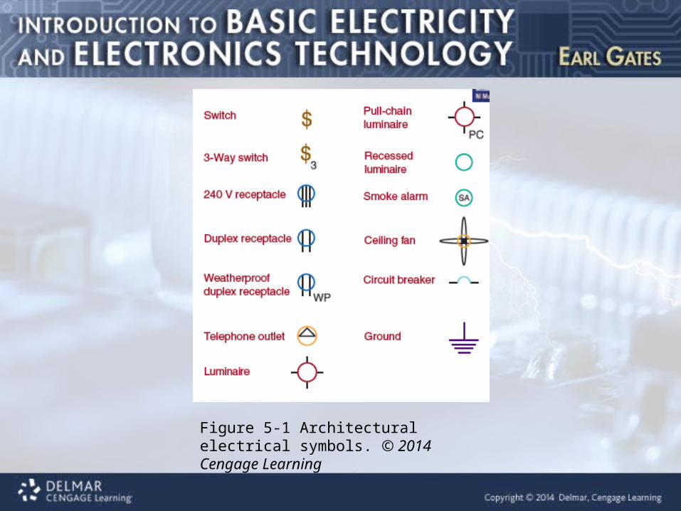
Figure 5-1 Architectural electrical symbols. © 2014 Cengage Learning
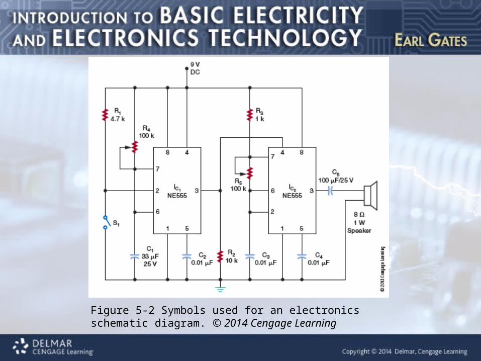
Figure 5-2 Symbols used for an electronics schematic diagram. © 2014 Cengage Learning
Schematic Diagram
• Basic reference for a circuit• Gives all necessary specifications• Circuit block diagram
– Shows how component blocks are connected• Analog schematics appear different from
digital schematics
Schematic Diagram (cont’d.)
• Tight component grouping of analog components– Important to show in schematic diagram
• Digital circuits have many common signals– Common signals are labeled– Not every connection is shown as a line
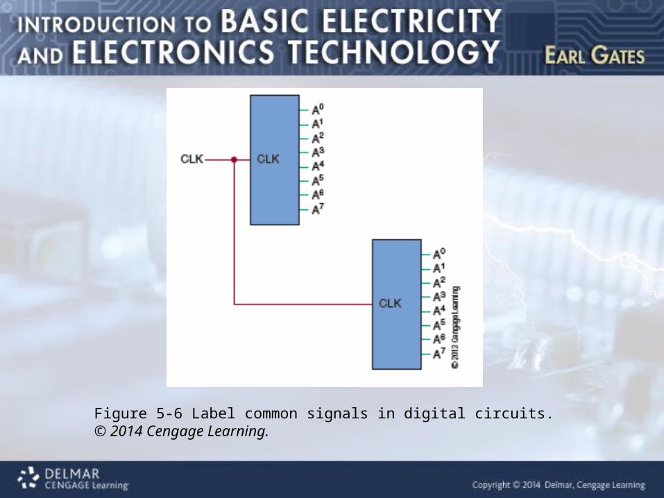
Figure 5-6 Label common signals in digital circuits. © 2014 Cengage Learning.
Schematic Diagram (cont’d.)
• Show entire circuit in as few drawings as possible
• Techniques– Group subcircuit components together– Signal flow proceeds from left to right
• Input on the left, output on the right
– Highest voltage at the top of the drawing
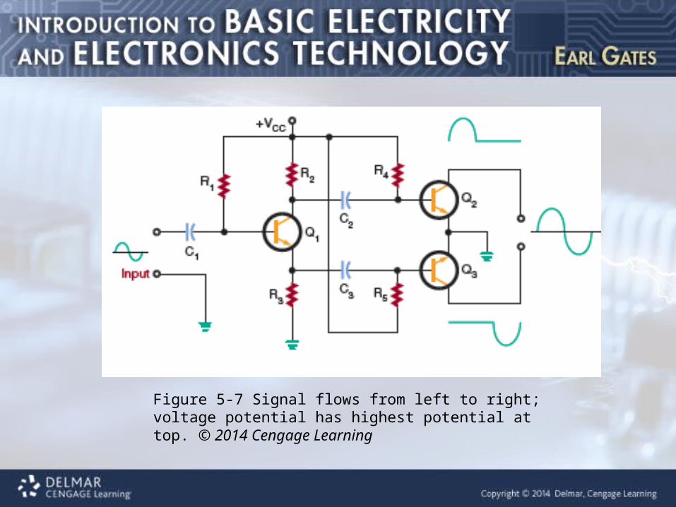
Figure 5-7 Signal flows from left to right; voltage potential has highest potential at top. © 2014 Cengage Learning
Schematic Diagram (cont’d.)
• Techniques (cont’d.)– Signal lines should cross as little as possible– Label components starting at top left
• Move down and back to the top, repeating across schematic
– Critical leads should be short or isolated from other signals
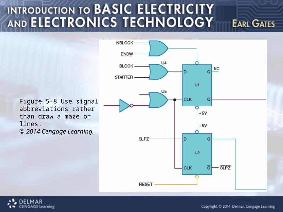
Figure 5-8 Use signal abbreviations rather than draw a maze of lines.© 2014 Cengage Learning.
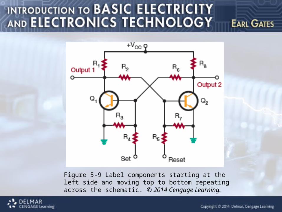
Figure 5-9 Label components starting at the left side and moving top to bottom repeating across the schematic. © 2014 Cengage Learning.
Schematic Diagram (cont’d.)• Techniques (cont’d.) :• Clearly indicate external components and
connectors• Label IC pins, including power supply inputs• Tie unused IC logic gates or extra subcircuit
inputs to the appropriate power supply level– Include any extra components added during
the construction process
Schematic Diagram (cont’d.)
• Variable components– Include an arrow as part of their symbol
• Arrows pointing away from a symbol:– Indicate it is giving off energy
• Arrows pointing toward a symbol:– Indicate it is receiving energy
• Letter symbols used to identify leads
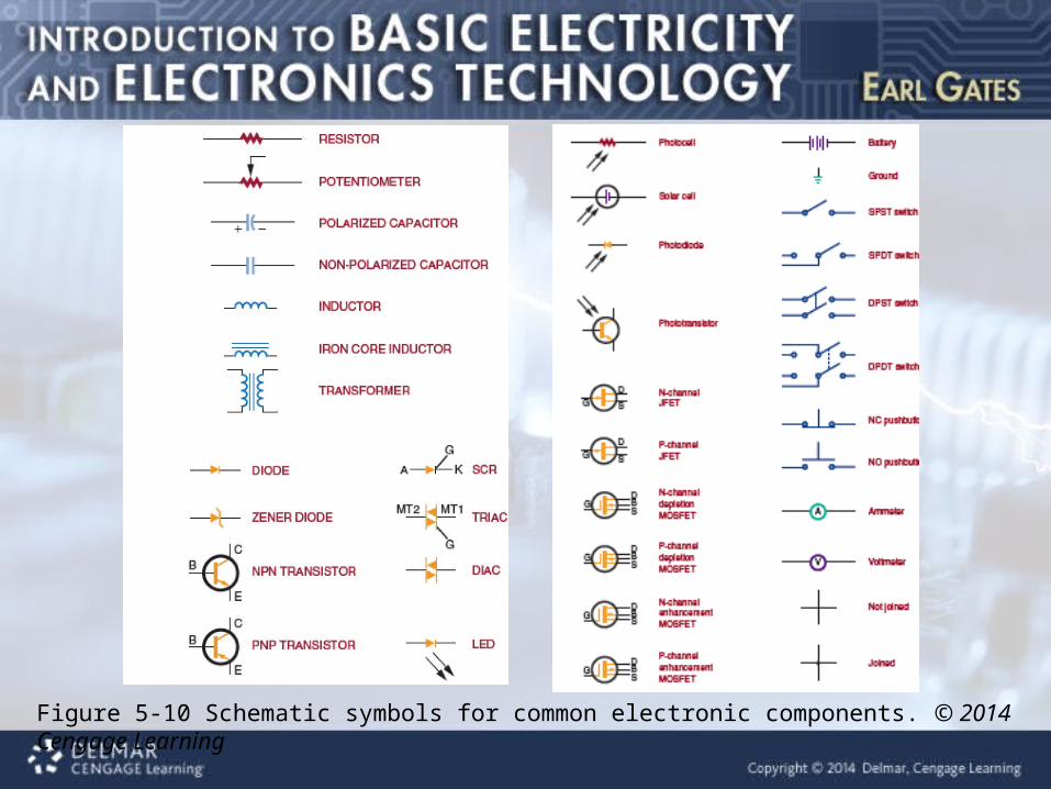
Figure 5-10 Schematic symbols for common electronic components. © 2014 Cengage Learning
Schematic Diagram (cont’d.)
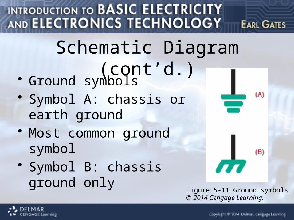
• Ground symbols• Symbol A: chassis or earth
ground• Most common ground symbol• Symbol B: chassis ground only
Figure 5-11 Ground symbols.© 2014 Cengage Learning.
Schematic Diagram (cont’d.)
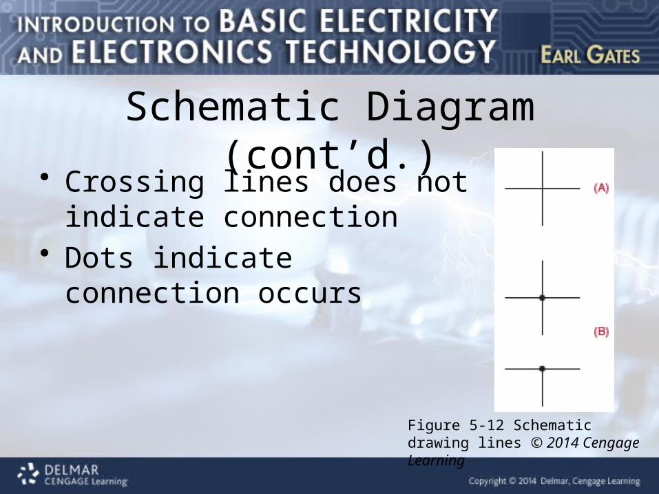
• Crossing lines does not indicate connection
• Dots indicate connection occurs
Figure 5-12 Schematic drawing lines © 2014 Cengage Learning
Schematic Diagram (cont’d.)
• Tools to create schematic diagrams• Common drafting tools• Computer aided design• Electronic circuit simulation programs
– Multisim– Circuit Wizard
Breadboarding• Breadboard :• Platform for building prototype electronic
circuit• Essential step to prove a circuit design
works• Solderless breadboards
– Developed in 1971– Allow circuits to be assembled and altered
quickly
Breadboarding (cont’d.)
• Virtual breadboarding– Assembling and testing a circuit using circuit
simulation programs
Recommended