Chapter 4Network Layer
Computer Networking: A Top Down Approach 6th edition Jim Kurose, Keith RossAddison-WesleyMarch 2012
A note on the use of these ppt slides:We’re making these slides freely available to all (faculty, students, readers).
They’re in PowerPoint form so you see the animations; and can add, modify,
and delete slides (including this one) and slide content to suit your needs.
They obviously represent a lot of work on our part. In return for use, we only
ask the following: If you use these slides (e.g., in a class) that you mention their source
(after all, we’d like people to use our book!)
If you post any slides on a www site, that you note that they are adapted
from (or perhaps identical to) our slides, and note our copyright of this
material.
Thanks and enjoy! JFK/KWR
All material copyright 1996-2012J.F Kurose and K.W. Ross, All Rights Reserved
Network Layer 4-1

Network Layer 4-2
Chapter 4: network layer
chapter goals: understand principles behind network layer
services: network layer service models
forwarding versus routing
how a router works
routing (path selection)
broadcast, multicast
instantiation, implementation in the Internet
Network Layer 4-3
4.1 introduction
4.2 virtual circuit and datagram networks
4.3 what’s inside a router
4.4 IP: Internet Protocol datagram format
IPv4 addressing
ICMP
IPv6
4.5 routing algorithms link state
distance vector
hierarchical routing
4.6 routing in the Internet RIP
OSPF
BGP
4.7 broadcast and multicast routing
Chapter 4: outline

Curso de Especialização em Redes de
Computadores – INF502
4
Interconexão de Redes

Curso de Especialização em Redes de
Computadores – INF502
5
A Internet

Curso de Especialização em Redes de
Computadores – INF502
6
A Internet

Curso de Especialização em Redes de
Computadores – INF502
7
Estatística de Usuários da Internet
Número de usuários mundiais ~ 2.400.000.000 (34% população do planeta)
Número de usuários no Brasil ~ 88.500.000 (45% da população)
fonte: http://www.internetworldstats.com/stats.htm

Network Layer 4-8
Network layer
transport segment from sending to receiving host
on sending side encapsulates segments into datagrams
on receiving side, delivers segments to transport layer
network layer protocols in every host, router
router examines header fields in all IP datagrams passing through it
application
transport
network
data link
physical
application
transport
network
data link
physical
network
data link
physical network
data link
physical
network
data link
physical
network
data link
physical
network
data link
physical
network
data link
physical
network
data link
physical
network
data link
physical
network
data link
physical
network
data link
physicalnetwork
data link
physical

Network Layer 4-9
Two key network-layer
functions forwarding: move
packets from router’s input to appropriate router output
routing: determine route taken by packets from source to dest.
routing algorithms
analogy:
routing: process of planning trip from source to dest
forwarding: process of getting through single interchange

Network Layer 4-10
1
23
0111
value in arriving
packet’s header
routing algorithm
local forwarding table
header value output link
0100
0101
0111
1001
3
2
2
1
Interplay between routing and forwarding
routing algorithm determines
end-end-path through network
forwarding table determines
local forwarding at this router

Network Layer 4-11
Connection setup
3rd important function in some network architectures: ATM, frame relay, X.25
before datagrams flow, two end hosts andintervening routers establish virtual connection routers get involved
network vs transport layer connection service: network: between two hosts (may also involve
intervening routers in case of VCs)
transport: between two processes
Network Layer 4-12
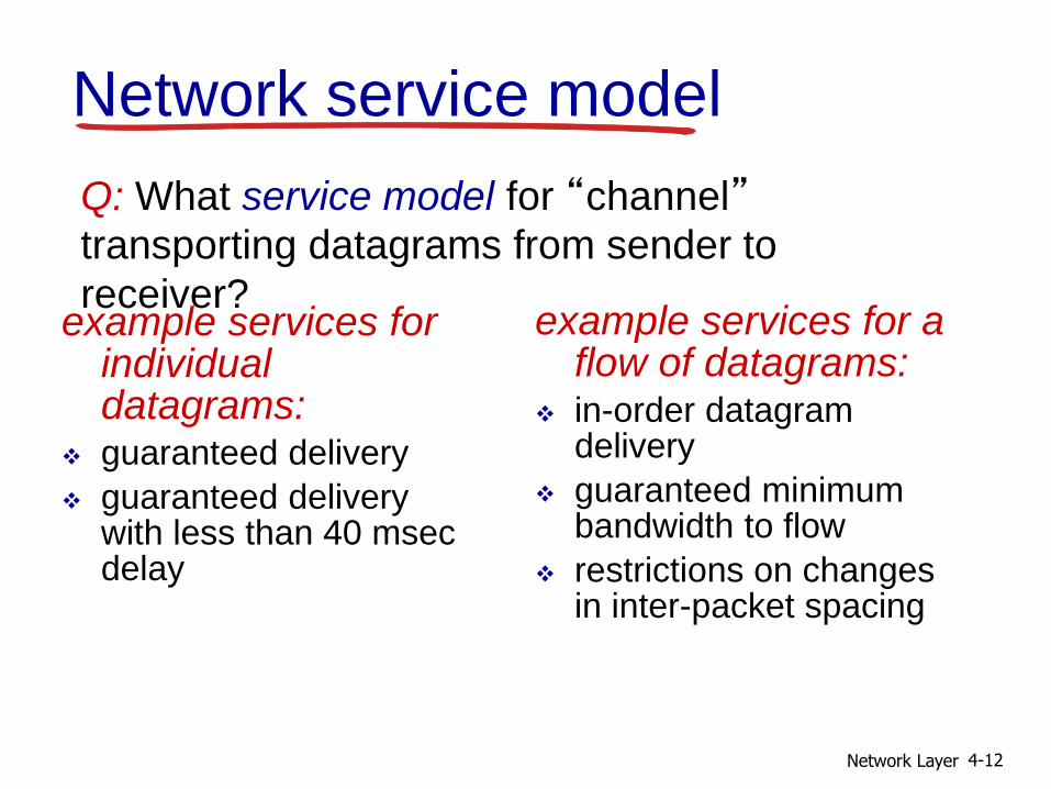
Network service model
Q: What service model for “channel”transporting datagrams from sender to
receiver?example services for
individual datagrams:
guaranteed delivery
guaranteed delivery with less than 40 msec delay
example services for a flow of datagrams:
in-order datagram delivery
guaranteed minimum bandwidth to flow
restrictions on changes in inter-packet spacing

Network Layer 4-13
Network layer service models:
Network
Architecture
Internet
ATM
ATM
ATM
ATM
Service
Model
best effort
CBR
VBR
ABR
UBR
Bandwidth
none
constant
rate
guaranteed
rate
guaranteed
minimum
none
Loss
no
yes
yes
no
no
Order
no
yes
yes
yes
yes
Timing
no
yes
yes
no
no
Congestion
feedback
no (inferred
via loss)
no
congestion
no
congestion
yes
no
Guarantees ?

Network Layer 4-14
4.1 introduction
4.2 virtual circuit and datagram networks
4.3 what’s inside a router
4.4 IP: Internet Protocol datagram format
IPv4 addressing
ICMP
IPv6
4.5 routing algorithms link state
distance vector
hierarchical routing
4.6 routing in the Internet RIP
OSPF
BGP
4.7 broadcast and multicast routing
Chapter 4: outline

Network Layer 4-15
Connection, connection-less
service
datagram network provides network-layer connectionless service
virtual-circuit network provides network-layer connection service
analogous to TCP/UDP connecton-oriented / connectionless transport-layer services, but:
service: host-to-host
no choice: network provides one or the other
implementation: in network core

Network Layer 4-16
Virtual circuits
call setup, teardown for each call before data can flow
each packet carries VC identifier (not destination host address)
every router on source-dest path maintains “state”for each passing connection
link, router resources (bandwidth, buffers) may be allocated to VC (dedicated resources = predictable service)
“source-to-dest path behaves much like telephone circuit” performance-wise
network actions along source-to-dest path
Network Layer 4-17
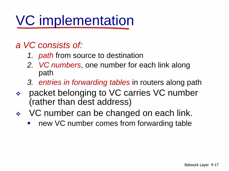
VC implementation
a VC consists of:1. path from source to destination
2. VC numbers, one number for each link along path
3. entries in forwarding tables in routers along path
packet belonging to VC carries VC number (rather than dest address)
VC number can be changed on each link. new VC number comes from forwarding table

Network Layer 4-18
VC forwarding table
12 22 32
12
3
VC number
interfacenumber
Incoming interface Incoming VC # Outgoing interface Outgoing VC #
1 12 3 22
2 63 1 18
3 7 2 17
1 97 3 87
… … … …
forwarding table innorthwest router:
VC routers maintain connection state information!

Network Layer 4-19
application
transport
network
data link
physical
Virtual circuits: signaling
protocols used to setup, maintain teardown VC
used in ATM, frame-relay, X.25
not used in today’s Internet
1. initiate call 2. incoming call
3. accept call4. call connected
5. data flow begins 6. receive dataapplication
transport
network
data link
physical
Network Layer 4-20
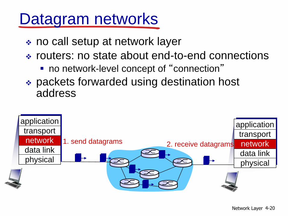
Datagram networks
no call setup at network layer
routers: no state about end-to-end connections no network-level concept of “connection”
packets forwarded using destination host address
1. send datagrams
application
transport
network
data link
physical
application
transport
network
data link
physical
2. receive datagrams

Network Layer 4-21
1
23
Datagram forwarding table
IP destination address in
arriving packet’s header
routing algorithm
local forwarding table
dest address output link
address-range 1
address-range 2
address-range 3
address-range 4
3
2
2
1
4 billion IP addresses, so rather than list individual destination addresslist range of addresses(aggregate table entries)

Network Layer 4-22
Destination Address Range
11001000 00010111 00010000 00000000
through11001000 00010111 00010111 11111111
11001000 00010111 00011000 00000000
through11001000 00010111 00011000 11111111
11001000 00010111 00011001 00000000
through11001000 00010111 00011111 11111111
otherwise
Link Interface
0
1
2
3
Q: but what happens if ranges don’t divide up so nicely?
Datagram forwarding table

Network Layer 4-23
Longest prefix matching
Destination Address Range
11001000 00010111 00010*** *********
11001000 00010111 00011000 *********
11001000 00010111 00011*** *********
otherwise
DA: 11001000 00010111 00011000 10101010
examples:
DA: 11001000 00010111 00010110 10100001 which interface?
which interface?
when looking for forwarding table entry for given destination address, use longest address prefix that matches destination address.
longest prefix matching
Link interface
0
1
2
3
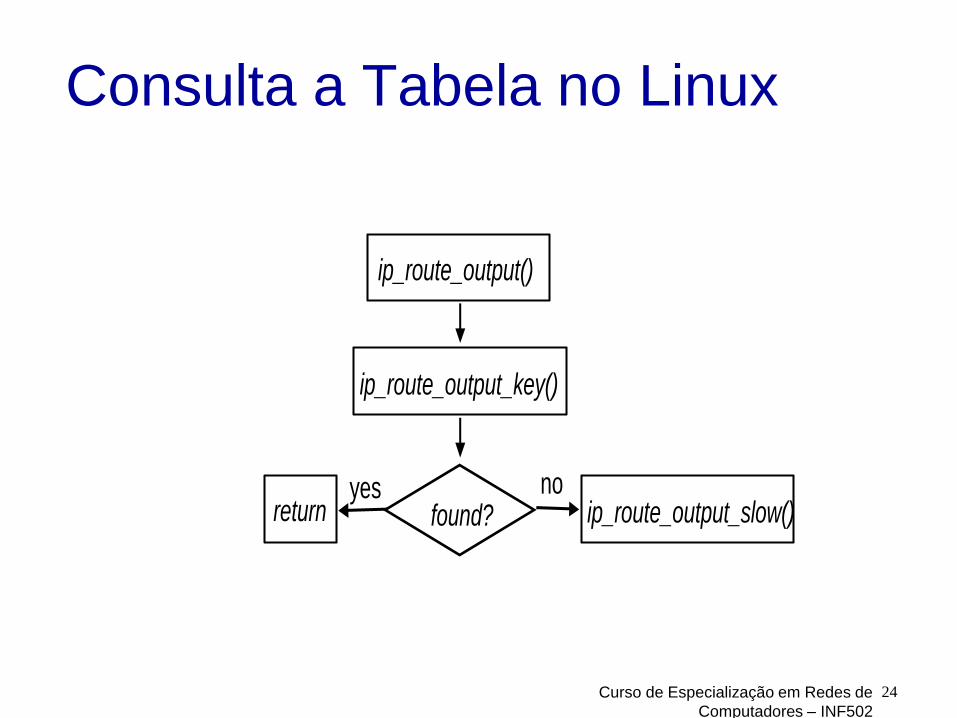
Consulta a Tabela no Linux
Curso de Especialização em Redes de
Computadores – INF502
24
ip_route_output()
ip_route_output_key()
return ip_route_output_slow() found? yes no

Cache para Acesso a Tabela
Curso de Especialização em Redes de
Computadores – INF502
25
rt_hash_table
chain
chain
chain
rtable u.rt_next
rtable

Estrutura da Tabela de
Roteamento
Curso de Especialização em Redes de
Computadores – INF502
26
fib_table
tb_data
fn_hash
fn_zones[32]
fn_zone_list
fn_zones[0]
fn_zones[1]
fn_zones[2]
fz_next
fz_hash[..]
fn_zone
fz_next
fz_hash[..]
fn_zone
fz_next
fz_hash[..]
fn_zone
fib_node
fn_next
fn_info
fib_node
fn_next
fn_info
fib_info
fib_nh
fib_nh
nh_gw
nh_dev

Network Layer 4-27
Datagram or VC network: why?
Internet (datagram) data exchange among
computers “elastic” service, no strict
timing req.
many link types different characteristics
uniform service difficult
“smart” end systems (computers) can adapt, perform control,
error recovery
simple inside network, complexity at “edge”
ATM (VC) evolved from telephony human conversation:
strict timing, reliability requirements
need for guaranteed service
“dumb” end systems telephones complexity inside
network

Network Layer 4-28
4.1 introduction
4.2 virtual circuit and datagram networks
4.3 what’s inside a router
4.4 IP: Internet Protocol datagram format
IPv4 addressing
ICMP
IPv6
4.5 routing algorithms link state
distance vector
hierarchical routing
4.6 routing in the Internet RIP
OSPF
BGP
4.7 broadcast and multicast routing
Chapter 4: outline

Network Layer 4-29
Router architecture overviewtwo key router functions: run routing algorithms/protocol (RIP, OSPF, BGP)
forwarding datagrams from incoming to outgoing link
high-seed switching
fabric
routing processor
router input ports router output ports
forwarding data
plane (hardware)
routing, management
control plane (software)
forwarding tables computed,
pushed to input ports
Network Layer 4-30
line
termination
link layer
protocol(receive)
lookup,
forwarding
queueing
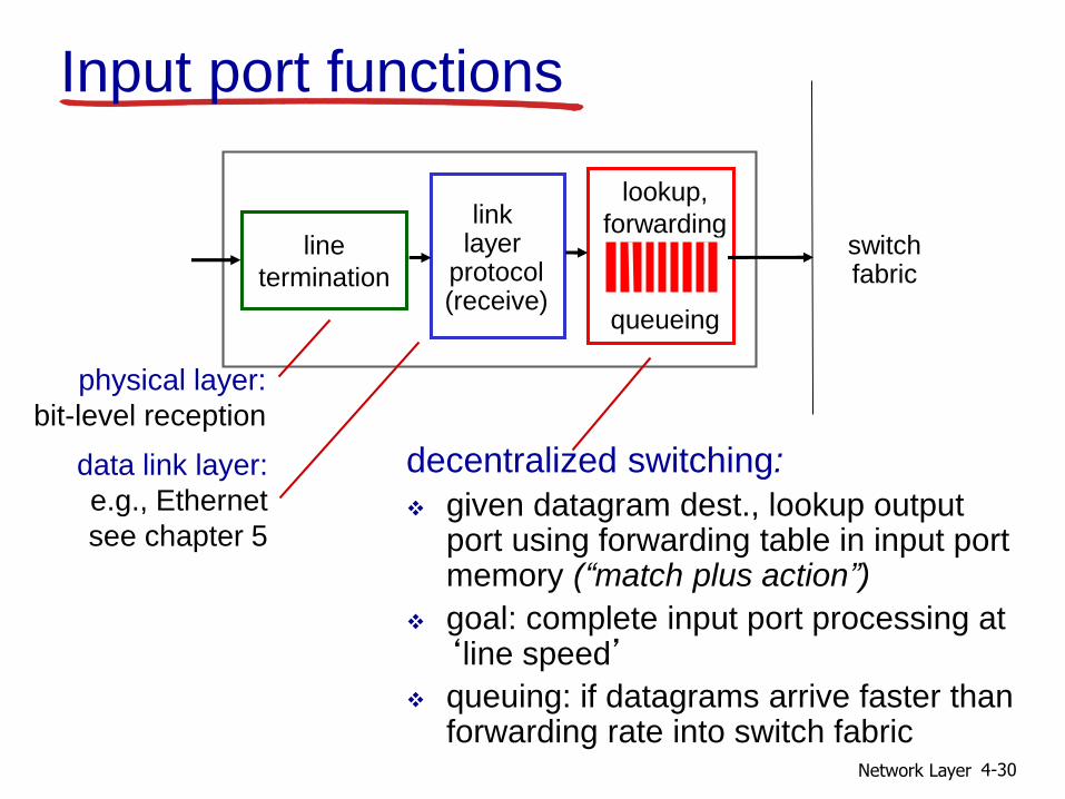
Input port functions
decentralized switching:
given datagram dest., lookup output port using forwarding table in input port memory (“match plus action”)
goal: complete input port processing at ‘line speed’
queuing: if datagrams arrive faster than forwarding rate into switch fabric
physical layer:
bit-level reception
data link layer:
e.g., Ethernet
see chapter 5
switchfabric

Network Layer 4-31
Switching fabrics
transfer packet from input buffer to appropriate output buffer
switching rate: rate at which packets can be transfer from inputs to outputs often measured as multiple of input/output line rate
N inputs: switching rate N times line rate desirable
three types of switching fabrics
memory
memory
bus crossbar

Network Layer 4-32
Switching via memory
first generation routers: traditional computers with switching under direct
control of CPU
packet copied to system’s memory
speed limited by memory bandwidth (2 bus crossings per datagram)
inputport
(e.g.,Ethernet)
memory
outputport
(e.g.,Ethernet)
system bus

Network Layer 4-33
Switching via a bus
datagram from input port memory
to output port memory via a shared bus
bus contention: switching speed limited by bus bandwidth
32 Gbps bus, Cisco 5600: sufficient speed for access and enterprise routers
bus

Network Layer 4-34
Switching via interconnection
network
overcome bus bandwidth limitations
banyan networks, crossbar, other interconnection nets initially developed to connect processors in multiprocessor
advanced design: fragmenting datagram into fixed length cells, switch cells through the fabric.
Cisco 12000: switches 60 Gbps through the interconnection network
crossbar

Network Layer 4-35
Output ports
buffering required when datagrams arrive from fabric faster than the transmission rate
scheduling discipline chooses among queued datagrams for transmission
line
termination
link layer
protocol(send)
switchfabric
datagram
buffer
queueing

Network Layer 4-36
Output port queueing
buffering when arrival rate via switch exceeds output line speed
queueing (delay) and loss due to output port buffer overflow!
at t, packets more
from input to output
one packet time later
switch
fabric
switch
fabric

Network Layer 4-37
How much buffering?
RFC 3439 rule of thumb: average buffering equal to “typical” RTT (say 250 msec) times link capacity C e.g., C = 10 Gpbs link: 2.5 Gbit buffer
recent recommendation: with N flows, buffering equal to
RTT C.
N

Network Layer 4-38
Input port queuing
fabric slower than input ports combined -> queueing may occur at input queues
queueing delay and loss due to input buffer overflow!
Head-of-the-Line (HOL) blocking: queued datagram at front of queue prevents others in queue from moving forward
output port contention:
only one red datagram can be
transferred.
lower red packet is blocked
switch
fabric
one packet time
later: green packet
experiences HOL
blocking
switch
fabric

Network Layer 4-39
4.1 introduction
4.2 virtual circuit and datagram networks
4.3 what’s inside a router
4.4 IP: Internet Protocol datagram format
IPv4 addressing
ICMP
IPv6
4.5 routing algorithms link state
distance vector
hierarchical routing
4.6 routing in the Internet RIP
OSPF
BGP
4.7 broadcast and multicast routing
Chapter 4: outline

Network Layer 4-40
The Internet network layer
forwarding
table
host, router network layer functions:
routing protocols• path selection
• RIP, OSPF, BGP
IP protocol• addressing conventions
• datagram format
• packet handling conventions
ICMP protocol• error reporting
• router
“signaling”
transport layer: TCP, UDP
link layer
physical layer
network
layer

Implementação IP - Linux
Curso de Especialização em Redes de
Computadores – INF502
41
udp_v4_rcv
UDP
tcp_v4_rcv
TCP
raw_v4_input
Raw IP
Medium Access Control (MAC)
net_tx_action
dev_queue_xmit
ip_output
ip_finish_output
ip_finish_output2
ip_push_pending_frames
ip_append_data ip_append_page
TCP UDP Raw IP
dst_output
skb->dst->output
IP
Layer
Transport
Layer
ip_queue_xmit
ip_local_deliver_finish
ip_route_output_flow
__ip_route_output_key
ip_route_output_slow
ip_rcv
dst_input
ip_route__input
ip_local_deliver
skb->dst->input
ip_rcv_finish
netif_receive_skb
net_rx_action Data link
Layer

Network Layer 4-42
ver length
32 bits
data
(variable length,
typically a TCP
or UDP segment)
16-bit identifier
header
checksum
time to
live
32 bit source IP address
head.
len
type of
service
flgsfragment
offsetupper
layer
32 bit destination IP address
options (if any)
IP datagram formatIP protocol version
number
header length
(bytes)
upper layer protocol
to deliver payload to
total datagram
length (bytes)
“type” of data for
fragmentation/
reassemblymax number
remaining hops
(decremented at
each router)
e.g. timestamp,
record route
taken, specify
list of routers
to visit.
how much overhead?
20 bytes of TCP
20 bytes of IP
= 40 bytes + app layer overhead

Network Layer 4-43
IP fragmentation, reassembly
network links have MTU (max.transfer size) -largest possible link-level frame
different link types, different MTUs
large IP datagram divided (“fragmented”) within net
one datagram becomes several datagrams
“reassembled” only at final destination
IP header bits used to identify, order related fragments
fragmentation:
in: one large datagram
out: 3 smaller datagrams
reassembly
…
…

Network Layer 4-44
ID
=xoffset
=0
fragflag
=0
length
=4000
ID
=xoffset
=0
fragflag
=1
length
=1500
ID
=xoffset
=185
fragflag
=1
length
=1500
ID
=xoffset
=370
fragflag
=0
length
=1040
one large datagram becomes
several smaller datagrams
example: 4000 byte datagram
MTU = 1500 bytes
1480 bytes in
data field
offset =
1480/8
IP fragmentation, reassembly

Network Layer 4-45
4.1 introduction
4.2 virtual circuit and datagram networks
4.3 what’s inside a router
4.4 IP: Internet Protocol datagram format
IPv4 addressing
ICMP
IPv6
4.5 routing algorithms link state
distance vector
hierarchical routing
4.6 routing in the Internet RIP
OSPF
BGP
4.7 broadcast and multicast routing
Chapter 4: outline

Network Layer 4-46
IP addressing: introduction
IP address: 32-bit identifier for host, router interface
interface: connection between host/router and physical link router’s typically have
multiple interfaces
host typically has one or two interfaces (e.g., wired Ethernet, wireless 802.11)
IP addresses associated with each interface
223.1.1.1
223.1.1.2
223.1.1.3
223.1.1.4 223.1.2.9
223.1.2.2
223.1.2.1
223.1.3.2223.1.3.1
223.1.3.27
223.1.1.1 = 11011111 00000001 00000001 00000001
223 1 11

Network Layer 4-47
IP addressing: introduction
Q: how are interfaces actually connected?
A: we’ll learn about that in chapter 5, 6.
223.1.1.1
223.1.1.2
223.1.1.3
223.1.1.4 223.1.2.9
223.1.2.2
223.1.2.1
223.1.3.2223.1.3.1
223.1.3.27
A: wired Ethernet interfaces
connected by Ethernet switches
A: wireless WiFi interfaces
connected by WiFi base station
For now: don’t need to worry
about how one interface is
connected to another (with no
intervening router)

Network Layer 4-48
Subnets
IP address:subnet part - high order bits
host part - low order bits
what’s a subnet ?device interfaces with same subnet part of IP address
can physically reach each other without intervening router network consisting of 3 subnets
223.1.1.1
223.1.1.3
223.1.1.4 223.1.2.9
223.1.3.2223.1.3.1
subnet
223.1.1.2
223.1.3.27223.1.2.2
223.1.2.1

Network Layer 4-49
recipe
to determine the subnets, detach each interface from its host or router, creating islands of isolated networks
each isolated network is called a subnet
subnet mask: /24
Subnets223.1.1.0/24
223.1.2.0/24
223.1.3.0/24
223.1.1.1
223.1.1.3
223.1.1.4 223.1.2.9
223.1.3.2223.1.3.1
subnet
223.1.1.2
223.1.3.27223.1.2.2
223.1.2.1

Network Layer 4-50
how many? 223.1.1.1
223.1.1.3
223.1.1.4
223.1.2.2223.1.2.1
223.1.2.6
223.1.3.2223.1.3.1
223.1.3.27
223.1.1.2
223.1.7.0
223.1.7.1
223.1.8.0223.1.8.1
223.1.9.1
223.1.9.2
Subnets

Network Layer 4-51
IP addressing: CIDR
CIDR: Classless InterDomain Routing subnet portion of address of arbitrary length
address format: a.b.c.d/x, where x is # bits in subnet portion of address
11001000 00010111 00010000 00000000
subnet
part
host
part
200.23.16.0/23

Network Layer 4-52
IP addresses: how to get one?
Q: How does a host get IP address?
hard-coded by system admin in a file Windows: control-panel->network->configuration-
>tcp/ip->properties
UNIX: /etc/rc.config
DHCP: Dynamic Host Configuration Protocol: dynamically get address from as server
“plug-and-play”

Network Layer 4-53
DHCP: Dynamic Host Configuration Protocol
goal: allow host to dynamically obtain its IP address from network server when it joins network
can renew its lease on address in use
allows reuse of addresses (only hold address while connected/“on”)
support for mobile users who want to join network (more shortly)
DHCP overview: host broadcasts “DHCP discover” msg [optional]
DHCP server responds with “DHCP offer” msg [optional]
host requests IP address: “DHCP request” msg
DHCP server sends address: “DHCP ack” msg

Network Layer 4-54
DHCP client-server scenario
223.1.1.0/24
223.1.2.0/24
223.1.3.0/24
223.1.1.1
223.1.1.3
223.1.1.4 223.1.2.9
223.1.3.2223.1.3.1
223.1.1.2
223.1.3.27223.1.2.2
223.1.2.1
DHCPserver
arriving DHCPclient needs address in thisnetwork

Network Layer 4-55
DHCP server: 223.1.2.5 arrivingclient
DHCP discover
src : 0.0.0.0, 68
dest.: 255.255.255.255,67
yiaddr: 0.0.0.0
transaction ID: 654
DHCP offer
src: 223.1.2.5, 67
dest: 255.255.255.255, 68
yiaddrr: 223.1.2.4
transaction ID: 654
lifetime: 3600 secs
DHCP request
src: 0.0.0.0, 68
dest:: 255.255.255.255, 67
yiaddrr: 223.1.2.4
transaction ID: 655
lifetime: 3600 secs
DHCP ACK
src: 223.1.2.5, 67
dest: 255.255.255.255, 68
yiaddrr: 223.1.2.4
transaction ID: 655
lifetime: 3600 secs
DHCP client-server
scenario

Network Layer 4-56
DHCP: more than IP
addressesDHCP can return more than just allocated IP
address on subnet: address of first-hop router for client
name and IP address of DNS sever
network mask (indicating network versus host portion of address)

Network Layer 4-57
connecting laptop needs its IP address, addr of first-hop router, addr of DNS server: use DHCP
router with DHCP
server built into
router
DHCP request encapsulated in UDP, encapsulated in IP, encapsulated in 802.1 Ethernet Ethernet frame broadcast (dest: FFFFFFFFFFFF) on LAN, received at router running DHCP server
Ethernet demuxed to IP demuxed, UDP demuxed to DHCP
168.1.1.1
DHCP
UDP
IP
Eth
Phy
DHCP
DHCP
DHCP
DHCP
DHCP
DHCP
UDP
IP
Eth
Phy
DHCP
DHCP
DHCP
DHCPDHCP
DHCP: example

Network Layer 4-58
DCP server formulates DHCP ACK containing client’s IP address, IP address of first-hop router for client, name & IP address of DNS server
encapsulation of DHCP server, frame forwarded to client, demuxing up to DHCP at client
DHCP: example
router with DHCP
server built into
router
DHCP
DHCP
DHCP
DHCP
DHCP
UDP
IP
Eth
Phy
DHCP
DHCP
UDP
IP
Eth
Phy
DHCP
DHCP
DHCP
DHCP
client now knows its IP address, name and IP address of DSN server, IP address of its first-hop router

Network Layer 4-59
DHCP: Wireshark output (home LAN)
Message type: Boot Reply (2)Hardware type: EthernetHardware address length: 6Hops: 0Transaction ID: 0x6b3a11b7Seconds elapsed: 0Bootp flags: 0x0000 (Unicast)Client IP address: 192.168.1.101 (192.168.1.101)Your (client) IP address: 0.0.0.0 (0.0.0.0)Next server IP address: 192.168.1.1 (192.168.1.1)Relay agent IP address: 0.0.0.0 (0.0.0.0)Client MAC address: Wistron_23:68:8a (00:16:d3:23:68:8a)Server host name not givenBoot file name not givenMagic cookie: (OK)Option: (t=53,l=1) DHCP Message Type = DHCP ACKOption: (t=54,l=4) Server Identifier = 192.168.1.1Option: (t=1,l=4) Subnet Mask = 255.255.255.0Option: (t=3,l=4) Router = 192.168.1.1Option: (6) Domain Name Server
Length: 12; Value: 445747E2445749F244574092; IP Address: 68.87.71.226;IP Address: 68.87.73.242; IP Address: 68.87.64.146
Option: (t=15,l=20) Domain Name = "hsd1.ma.comcast.net."
reply
Message type: Boot Request (1)Hardware type: EthernetHardware address length: 6Hops: 0Transaction ID: 0x6b3a11b7Seconds elapsed: 0Bootp flags: 0x0000 (Unicast)Client IP address: 0.0.0.0 (0.0.0.0)Your (client) IP address: 0.0.0.0 (0.0.0.0)Next server IP address: 0.0.0.0 (0.0.0.0)Relay agent IP address: 0.0.0.0 (0.0.0.0)Client MAC address: Wistron_23:68:8a (00:16:d3:23:68:8a)Server host name not givenBoot file name not givenMagic cookie: (OK)Option: (t=53,l=1) DHCP Message Type = DHCP RequestOption: (61) Client identifier
Length: 7; Value: 010016D323688A; Hardware type: EthernetClient MAC address: Wistron_23:68:8a (00:16:d3:23:68:8a)
Option: (t=50,l=4) Requested IP Address = 192.168.1.101Option: (t=12,l=5) Host Name = "nomad"Option: (55) Parameter Request List
Length: 11; Value: 010F03062C2E2F1F21F92B1 = Subnet Mask; 15 = Domain Name3 = Router; 6 = Domain Name Server44 = NetBIOS over TCP/IP Name Server……
request

Network Layer 4-60
IP addresses: how to get one?
Q: how does network get subnet part of IP addr?
A: gets allocated portion of its provider ISP’s address space
ISP's block 11001000 00010111 00010000 00000000 200.23.16.0/20
Organization 0 11001000 00010111 00010000 00000000 200.23.16.0/23
Organization 1 11001000 00010111 00010010 00000000 200.23.18.0/23
Organization 2 11001000 00010111 00010100 00000000 200.23.20.0/23
... ….. …. ….
Organization 7 11001000 00010111 00011110 00000000 200.23.30.0/23

Network Layer 4-61
Hierarchical addressing: route
aggregation
“Send me anything
with addresses
beginning
200.23.16.0/20”
200.23.16.0/23
200.23.18.0/23
200.23.30.0/23
Fly-By-Night-ISP
Organization 0
Organization 7Internet
Organization 1
ISPs-R-Us“Send me anything
with addresses
beginning
199.31.0.0/16”
200.23.20.0/23
Organization 2
.
.
.
.
.
.
hierarchical addressing allows efficient advertisement of routing
information:

Network Layer 4-62
ISPs-R-Us has a more specific route to Organization 1
“Send me anything
with addresses
beginning
200.23.16.0/20”
200.23.16.0/23
200.23.18.0/23
200.23.30.0/23
Fly-By-Night-ISP
Organization 0
Organization 7Internet
Organization 1
ISPs-R-Us“Send me anything
with addresses
beginning 199.31.0.0/16
or 200.23.18.0/23”
200.23.20.0/23
Organization 2
.
.
.
.
.
.
Hierarchical addressing: more specific
routes

Network Layer 4-63
IP addressing: the last word...
Q: how does an ISP get block of addresses?
A: ICANN: Internet Corporation for Assigned
Names and Numbers http://www.icann.org/
allocates addresses
manages DNS
assigns domain names, resolves disputes

Network Layer 4-64
NAT: network address
translation
10.0.0.1
10.0.0.2
10.0.0.3
10.0.0.4
138.76.29.7
local network
(e.g., home network)
10.0.0/24
rest of
Internet
datagrams with source or destination in this networkhave 10.0.0/24 address for source, destination (as usual)
all datagrams leavinglocal
network have samesingle source NAT IP
address: 138.76.29.7,different source port numbers

Network Layer 4-65
motivation: local network uses just one IP address as far as outside world is concerned:
range of addresses not needed from ISP: just one IP address for all devices
can change addresses of devices in local network without notifying outside world
can change ISP without changing addresses of devices in local network
devices inside local net not explicitly addressable, visible by outside world (a security plus)
NAT: network address
translation

Network Layer 4-66
implementation: NAT router must:
outgoing datagrams: replace (source IP address, port #) of every outgoing datagram to (NAT IP address, new port #)
. . . remote clients/servers will respond using (NAT IP address, new port #) as destination addr
remember (in NAT translation table) every (source IP address, port #) to (NAT IP address, new port #) translation pair
incoming datagrams: replace (NAT IP address, new port #) in dest fields of every incoming datagram with corresponding (source IP address, port #) stored in NAT table
NAT: network address
translation

Network Layer 4-67
10.0.0.1
10.0.0.2
10.0.0.3
S: 10.0.0.1, 3345
D: 128.119.40.186, 80
1
10.0.0.4
138.76.29.7
1: host 10.0.0.1 sends datagram to 128.119.40.186, 80
NAT translation table
WAN side addr LAN side addr
138.76.29.7, 5001 10.0.0.1, 3345
…… ……
S: 128.119.40.186, 80
D: 10.0.0.1, 33454
S: 138.76.29.7, 5001
D: 128.119.40.186, 802
2: NAT routerchanges datagramsource addr from10.0.0.1, 3345 to138.76.29.7, 5001,updates table
S: 128.119.40.186, 80
D: 138.76.29.7, 5001 3
3: reply arrivesdest. address:138.76.29.7, 5001
4: NAT routerchanges datagramdest addr from138.76.29.7, 5001 to 10.0.0.1, 3345
NAT: network address
translation

Network Layer 4-68
16-bit port-number field:
60,000 simultaneous connections with a single LAN-side address!
NAT is controversial:
routers should only process up to layer 3
violates end-to-end argument
• NAT possibility must be taken into account by
app designers, e.g., P2P applications
address shortage should instead be solved by IPv6
NAT: network address
translation

Network Layer 4-69
NAT traversal problem
client wants to connect to server with address 10.0.0.1 server address 10.0.0.1 local to
LAN (client can’t use it as destination addr)
only one externally visible NATed address: 138.76.29.7
solution1: statically configure NAT to forward incoming connection requests at given port to server e.g., (123.76.29.7, port 2500)
always forwarded to 10.0.0.1 port 25000
10.0.0.1
10.0.0.4
NAT router
138.76.29.7
client
?

Network Layer 4-70
NAT traversal problem
solution 2: Universal Plug and Play (UPnP) Internet Gateway Device (IGD) Protocol. Allows NATed host to: learn public IP address
(138.76.29.7) add/remove port mappings
(with lease times)
i.e., automate static NAT port map configuration
10.0.0.1
NAT router
IGD

Network Layer 4-71
NAT traversal problem
solution 3: relaying (used in Skype)
NATed client establishes connection to relay
external client connects to relay
relay bridges packets between to connections
138.76.29.7
client
1. connection torelay initiatedby NATed host
2. connection torelay initiatedby client
3. relaying established
NAT router
10.0.0.1

Network Layer 4-72
4.1 introduction
4.2 virtual circuit and datagram networks
4.3 what’s inside a router
4.4 IP: Internet Protocol datagram format
IPv4 addressing
ICMP
IPv6
4.5 routing algorithms link state
distance vector
hierarchical routing
4.6 routing in the Internet RIP
OSPF
BGP
4.7 broadcast and multicast routing
Chapter 4: outline

Network Layer 4-73
ICMP: internet control message
protocol
used by hosts & routers to communicate network-level information error reporting:
unreachable host, network, port, protocol
echo request/reply (used by ping)
network-layer “above”IP: ICMP msgs carried in IP
datagrams
ICMP message: type, code plus first 8 bytes of IP datagram causing error
Type Code description
0 0 echo reply (ping)
3 0 dest. network unreachable
3 1 dest host unreachable
3 2 dest protocol unreachable
3 3 dest port unreachable
3 6 dest network unknown
3 7 dest host unknown
4 0 source quench (congestion
control - not used)
8 0 echo request (ping)
9 0 route advertisement
10 0 router discovery
11 0 TTL expired
12 0 bad IP header

Network Layer 4-74
Traceroute and ICMP
source sends series of UDP segments to dest first set has TTL =1
second set has TTL=2, etc.
unlikely port number
when nth set of datagrams arrives to nth router: router discards datagrams
and sends source ICMP messages (type 11, code 0)
ICMP messages includes name of router & IP address
when ICMP messages arrives, source records RTTs
stopping criteria:
UDP segment eventually arrives at destination host
destination returns ICMP “port unreachable” message (type 3, code 3)
source stops
3 probes
3 probes
3 probes
Network Layer 4-75
IPv6: motivation
initial motivation: 32-bit address space soon to be completely allocated.
additional motivation: header format helps speed processing/forwarding
header changes to facilitate QoS
IPv6 datagram format: fixed-length 40 byte header
no fragmentation allowed

Network Layer 4-76
IPv6 datagram format
priority: identify priority among datagrams in flow
flow Label: identify datagrams in same “flow.”(concept of“flow” not well defined).
next header: identify upper layer protocol for data
data
destination address(128 bits)
source address(128 bits)
payload len next hdr hop limit
flow labelpriver
32 bits

Network Layer 4-77
Other changes from IPv4
checksum: removed entirely to reduce processing time at each hop
options: allowed, but outside of header, indicated by “Next Header” field
ICMPv6: new version of ICMP additional message types, e.g. “Packet Too Big” multicast group management functions

Comparação IPv4 and IPv6 IPv4 Header IPv6 Header
Field’s name kept from IPv4 to IPv6
Fields not kept in IPv6
Name and position changed in IPv6
New field in IPv6
Lege
nd
Version Traffic Class Flow Label
Payload Length Next Header Hop Limit
Source Address
Destination Address
Version IHLType of
ServiceTotal Length
Identification FlagsFragment
Offset
Time to Live Protocol Header Checksum
Source Address
Destination Address
Options Padding
Curso de Especialização em Redes de
Computadores – INF502
79
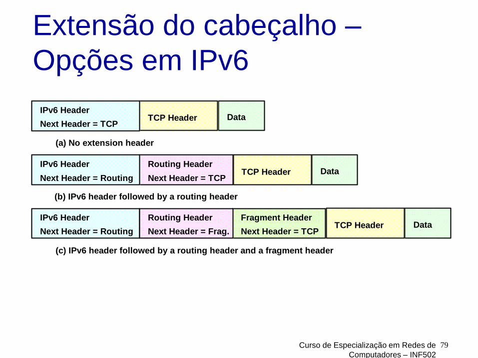
Extensão do cabeçalho –
Opções em IPv6
Next Header = TCP
IPv6 Header TCP Header Data
Next Header = TCP
Routing Header TCP Header Data
Next Header = Routing
IPv6 Header
Next Header = TCP
Fragment Header TCP Header Data
Next Header = Routing
IPv6 Header
Next Header = Frag.
Routing Header
(a) No extension header
(b) IPv6 header followed by a routing header
(c) IPv6 header followed by a routing header and a fragment header

Curso de Especialização em Redes de
Computadores – INF502
80
Ordem das extensões de
cabeçalho IPv6 (41)
Hop-By-Hop Options header (0)
Destination Options header (60)
Routing header (43)
Fragment header (44)
Authentication header (51)
Encapsulating Security Payload header (50)
Destination Options header (60)
Upper-layer header
• ICMPv6(58)
• TCP(6), UDP(17), RSVP(46), SCTP(132)

Curso de Especialização em Redes de
Computadores – INF502
81
Cabeçalho de fragmentação
A Fragmentação só é realizada na fonte e não nos roteadores intermediários
Campos semelhantes aos do
16 0 8 29 31
Next Header Reserved Fragment Offset R M
Identifier

Curso de Especialização em Redes de
Computadores – INF502
82
Exemplo de Fragmentação
IPv6 Header Fragment 1 Data
(a) Original packet
Fragment 2 Data Fragment 3 Data
IPv6 Header Fragment Header
(b) Fragments
Fragment 1 Data
IPv6 Header Fragment Header Fragment 2 Data
IPv6 Header Fragment Header Fragment 3 Data

Endereço IPv6
128 bits
Notação hexadecimal separada por “:”
3FFD:3600:0000:0000:0302:B3FF:FE3C: C0DB
Sequência de números de de 16 bits nulosseparados por “::”
3FFD:3600:0:0:0:0:1:A =>3FFD:3600::1:A
Curso de Especialização em Redes de
Computadores – INF502
83

Endereços reservados
Curso de Especialização em Redes de
Computadores – INF502
84
Prefix Address Type Portion
0000 0000 Reserved (IPv4 compatibility) 1/256
0000 0001 Unassigned 1/256
0000 001 Reserved for NSAP 1/128
0000 010 Reserved for IPX 1/128
0000 011 Unassigned 1/128
0000 1 Unassigned 1/32
0001 Unassigned 1/16
001 Aggregatable Global Unicast Address 1/8
010 Unassigned 1/8
011 Unassigned 1/8
100 Unassigned 1/8
101 Unassigned 1/8
110 Unassigned 1/8
1110 Unassigned 1/16
1111 0 Unassigned 1/32
1111 10 Unassigned 1/64
1111 110 Unassigned 1/128
1111 1110 0 Unassigned 1/512
1111 1110 10 Link Local Unicast Address 1/1024
1111 1110 11 Site Local Unicast Address 1/1024
1111 1111 Multicast Address 1/256

Endereço IPv6
Unicast IPv4 Compatible Adress
Global Unicast Adress
Link Local Unicast Adress
Multicast Começa com 11111111
Anycast Começa com prefixo de rede seguido de
sequência de zeros
Curso de Especialização em Redes de
Computadores – INF502
85

Curso de Especialização em Redes de
Computadores – INF502
86
Endereços IPv6 compatíveis
com IPv4
IPv4-compatible IPv6 Address:
00000000 IPv4 Address0000
32 32 bits
IPv4-Mapped IPv6 Address:
00000000 IPv4 AddressFFFF
32 32 bits
::FFFF:8C7B:65A0
::8C7B:65A0

Curso de Especialização em Redes de Computadores – INF502 87
Endereços IPv6 Unicast
Unicast Address without Internal Structure:
Node Address
Unicast Address with Subnet:
Subnet Prefix Interface ID
Unicast Unspecified Address:
00000000 0000
Unicast Loopback Address:
00000000 0001

Curso de Especialização em Redes de Computadores – INF502 88
ICMPv6
Versão do protocolo ICMP utilizada pelo protocolo Ipv6, basicamente as mesmas funcionalidades do ICMP
Realizar diagnósticos
Relatar erros de processamento de pacotes
Possui também funções adicionaisDescoberta de vizinhança (antes providas pelo protocolo ARP)
Gerenciamento de grupos Multicast (antes providas pelo protocolo IGMP).

Obtenção de endereço IPV6
Duas opções:
Stateless autoconfiguration
Stateful DHCP
Curso de Especialização em Redes de
Computadores – INF502
89

IPv6 Autoconfiguração
Pode-se obter endereços IPv6 automaticamente (substitui DHCP IPv4)
Endereços de enlace-local (link-local) são auto-configuráveis. Devem ser usados somente em enlaces locais (ex redes locais)
Roteadores e servidores devem ser configurados manualmete
Curso de Especialização em Redes de
Computadores – INF502
90

IPv6 Autoconfiguração
Interface pode ter mais de um endereço Ipv6: um link-local e outro Global
Endereço: identificador + token
Identificador obtido através de mensagens Router Advertisement
Curso de Especialização em Redes de
Computadores – INF502
91

IPv6 Auto-configuração
Token pode ser obtido endereço MAC EUI-64
Alternativa Randon Identifier (temporário)
Curso de Especialização em Redes de
Computadores – INF502
92

IPv6 Autoconfiguração
Após criar endereço em estado tentativa, verifica-se a unicidade do endereço através de envio de mensagem para outras interfaces no link (Dupliate Address Detection)
Após confirmação endereço usado como permanente, uso só após virar permanente
Curso de Especialização em Redes de
Computadores – INF502
93

IPv6 DHCPv6
Semelhante ao DHCP
Opera em modo cliente – servidor
Obtém endereço IPv6 e informações de configurações e segurança
Curso de Especialização em Redes de
Computadores – INF502
94

Network Layer 4-95
Transition from IPv4 to IPv6
not all routers can be upgraded simultaneously no “flag days” how will network operate with mixed IPv4 and
IPv6 routers?
tunneling: IPv6 datagram carried as payload in IPv4 datagram among IPv4 routers
IPv4 source, dest addr
IPv4 header fields
IPv4 datagram
IPv6 datagram
IPv4 payload
UDP/TCP payload
IPv6 source dest addr
IPv6 header fields

Pilhas Duais
Curso de Especialização em Redes de
Computadores – INF502
96

Network Layer 4-97
Tunneling
physical view:
IPv4 IPv4
A B
IPv6 IPv6
E
IPv6 IPv6
FC D
logical view:
IPv4 tunnel connecting IPv6 routers
E
IPv6 IPv6
FA B
IPv6 IPv6

Network Layer 4-98
flow: X
src: A
dest: F
data
A-to-B:IPv6
Flow: X
Src: A
Dest: F
data
src:B
dest: E
B-to-C:IPv6 inside
IPv4
E-to-F:IPv6
flow: X
src: A
dest: F
data
B-to-C:IPv6 inside
IPv4
Flow: X
Src: A
Dest: F
data
src:B
dest: E
physical view:A B
IPv6 IPv6
E
IPv6 IPv6
FC D
logical view:
IPv4 tunnel connecting IPv6 routers
E
IPv6 IPv6
FA B
IPv6 IPv6
Tunneling
IPv4 IPv4

6to4
Mecanismo de transição, não exige estabelecimento de túnel
Não é necessário que roteadores intermediários saibam 6to4
Procedimento: Atribui endereço IPv6 para host nativo IPv4
Encapsula pacote IPv6 em IPv4
Encaminha pacote entre roteadores 6to4
Curso de Especialização em Redes de
Computadores – INF502
99

6to4
Endereço 6to4 começa com 2002, seguido do endereço IPv4 (32 bits), seguido 16 bits escolhidos arbitrariamente
Curso de Especialização em Redes de
Computadores – INF502
100

6to4
Curso de Especialização em Redes de
Computadores – INF502
101

Teredo
6to4 exige que o endereço do destinatário tenha um endereço IPv4 válido, não permitindo que esteja atrás de NAT
Teredo encapsula Ipv4 em UDP/IPv4 – NAT não tem problema em encaminhar
Curso de Especialização em Redes de
Computadores – INF502
102

Tradutores
Soluções obsoletas tais como NAT-PT, NAPT-PT
SIIT (RFC 2765) - Stateless IP/ICMP Translation Algorithm (SIIT)
BIS (RFC 2767) e BIA (RFC 3338) – dual stack
Curso de Especialização em Redes de
Computadores – INF502
103

Estatística IPv6
Curso de Especialização em Redes de
Computadores – INF502
104

IPv6 na América do Sul
Curso de Especialização em Redes de
Computadores – INF502
105

Network Layer 4-106
4.1 introduction
4.2 virtual circuit and datagram networks
4.3 what’s inside a router
4.4 IP: Internet Protocol datagram format
IPv4 addressing
ICMP
IPv6
4.5 routing algorithms link state
distance vector
hierarchical routing
4.6 routing in the Internet RIP
OSPF
BGP
4.7 broadcast and multicast routing
Chapter 4: outline

Network Layer 4-107
1
23
IP destination address in
arriving packet’s header
routing algorithm
local forwarding table
dest address output link
address-range 1
address-range 2
address-range 3
address-range 4
3
2
2
1
Interplay between routing, forwarding
routing algorithm determines
end-end-path through network
forwarding table determines
local forwarding at this router

Network Layer 4-108
u
yx
wv
z
2
2
13
1
1
2
53
5
graph: G = (N,E)
N = set of routers = { u, v, w, x, y, z }
E = set of links ={ (u,v), (u,x), (v,x), (v,w), (x,w), (x,y), (w,y), (w,z), (y,z) }
Graph abstraction
aside: graph abstraction is useful in other network contexts, e.g.,
P2P, where N is set of peers and E is set of TCP connections
Network Layer 4-109
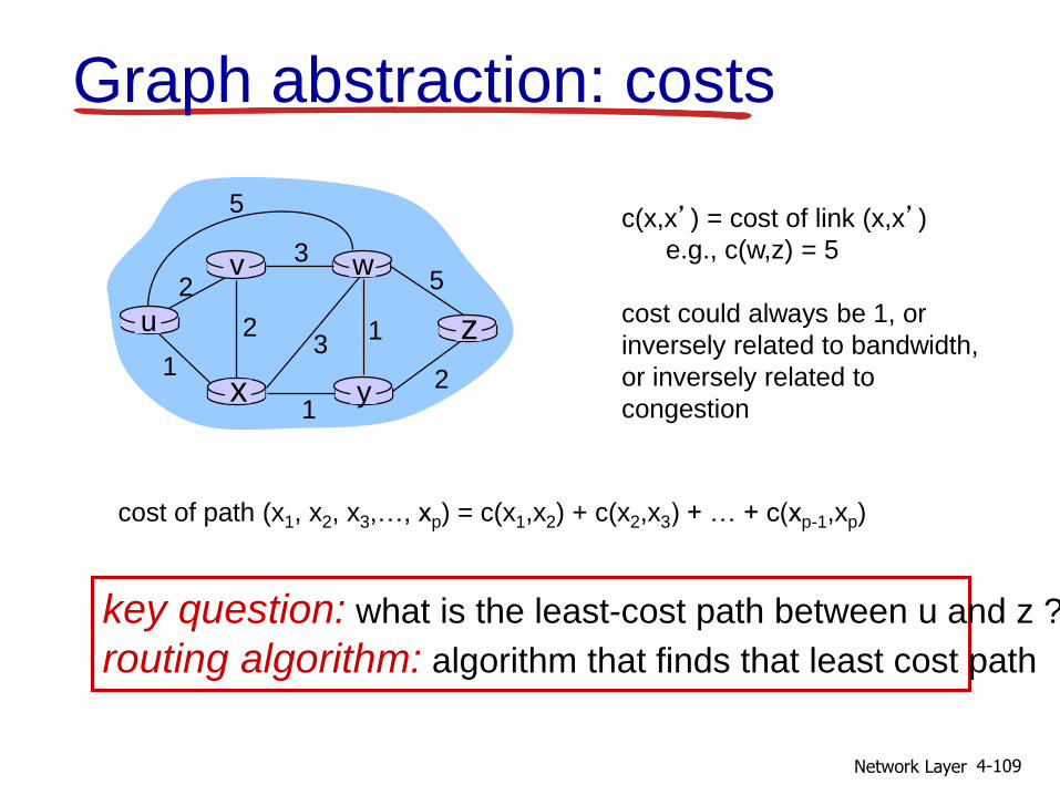
Graph abstraction: costs
u
yx
wv
z
2
2
13
1
1
2
53
5c(x,x’) = cost of link (x,x’)
e.g., c(w,z) = 5
cost could always be 1, or
inversely related to bandwidth,
or inversely related to
congestion
cost of path (x1, x2, x3,…, xp) = c(x1,x2) + c(x2,x3) + … + c(xp-1,xp)
key question: what is the least-cost path between u and z ?
routing algorithm: algorithm that finds that least cost path

Network Layer 4-110
Routing algorithm classification
Q: global or decentralized information?
global:
all routers have complete topology, link cost info
“link state” algorithms
decentralized:
router knows physically-connected neighbors, link costs to neighbors
iterative process of computation, exchange of info with neighbors
“distance vector”algorithms
Q: static or dynamic?
static:
routes change slowly over time
dynamic:
routes change more quickly
periodic update
in response to link cost changes

Network Layer 4-111
4.1 introduction
4.2 virtual circuit and datagram networks
4.3 what’s inside a router
4.4 IP: Internet Protocol datagram format
IPv4 addressing
ICMP
IPv6
4.5 routing algorithms link state
distance vector
hierarchical routing
4.6 routing in the Internet RIP
OSPF
BGP
4.7 broadcast and multicast routing
Chapter 4: outline

Network Layer 4-112
A Link-State Routing Algorithm
Dijkstra’s algorithm net topology, link costs
known to all nodes accomplished via “link
state broadcast” all nodes have same info
computes least cost paths from one node (‘source”) to all other nodes gives forwarding table for
that node
iterative: after k iterations, know least cost path to k dest.’s
notation: c(x,y): link cost from
node x to y; = ∞ if not direct neighbors
D(v): current value of cost of path from source to dest. v
p(v): predecessor node along path from source to v
N': set of nodes whose least cost path definitively known

Network Layer 4-113
Dijsktra’s Algorithm
1 Initialization:
2 N' = {u}
3 for all nodes v
4 if v adjacent to u
5 then D(v) = c(u,v)
6 else D(v) = ∞
7
8 Loop
9 find w not in N' such that D(w) is a minimum
10 add w to N'
11 update D(v) for all v adjacent to w and not in N' :
12 D(v) = min( D(v), D(w) + c(w,v) )
13 /* new cost to v is either old cost to v or known
14 shortest path cost to w plus cost from w to v */
15 until all nodes in N'

Network Layer 4-114
w3
4
v
x
u
5
37 4
y
8
z2
7
9
Dijkstra’s algorithm: example
Step N'D(v)
p(v)
0
1
2
3
4
5
D(w)p(w)
D(x)p(x)
D(y)p(y)
D(z)p(z)
u ∞ ∞ 7,u 3,u 5,u
uw ∞ 11,w6,w 5,u
14,x 11,w 6,wuwx
uwxv 14,x 10,v
uwxvy 12,y
notes: construct shortest path tree
by tracing predecessor nodes
ties can exist (can be broken arbitrarily)
uwxvyz

Network Layer 4-115
Dijkstra’s algorithm: another
example
Step
0
1
2
3
4
5
N'
u
ux
uxy
uxyv
uxyvw
uxyvwz
D(v),p(v)
2,u
2,u
2,u
D(w),p(w)
5,u
4,x
3,y
3,y
D(x),p(x)
1,u
D(y),p(y)
∞2,x
D(z),p(z)∞ ∞
4,y
4,y
4,y
u
yx
wv
z
2
2
13
1
1
2
53
5

Network Layer 4-116
Dijkstra’s algorithm: example (2)
u
yx
wv
z
resulting shortest-path tree from u:
v
x
y
w
z
(u,v)
(u,x)
(u,x)
(u,x)
(u,x)
destination link
resulting forwarding table in u:
Network Layer 4-117
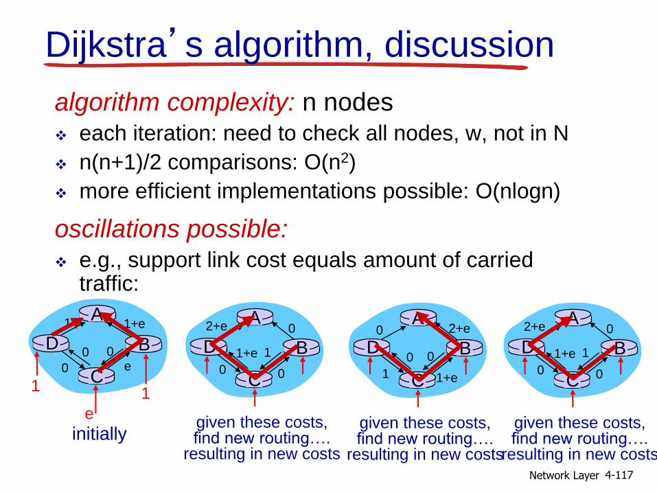
Dijkstra’s algorithm, discussion
algorithm complexity: n nodes each iteration: need to check all nodes, w, not in N
n(n+1)/2 comparisons: O(n2)
more efficient implementations possible: O(nlogn)
oscillations possible: e.g., support link cost equals amount of carried
traffic:
A
D
C
B
1 1+e
e0
e
1 1
0 0
initially
A
D
C
B
given these costs,find new routing….
resulting in new costs
2+e 0
00
1+e 1
A
D
C
B
given these costs,find new routing….
resulting in new costs
0 2+e
1+e1
0 0
A
D
C
B
given these costs,find new routing….
resulting in new costs
2+e 0
00
1+e 1

Network Layer 4-118
4.1 introduction
4.2 virtual circuit and datagram networks
4.3 what’s inside a router
4.4 IP: Internet Protocol datagram format
IPv4 addressing
ICMP
IPv6
4.5 routing algorithms link state
distance vector
hierarchical routing
4.6 routing in the Internet RIP
OSPF
BGP
4.7 broadcast and multicast routing
Chapter 4: outline

Network Layer 4-119
Distance vector algorithm
Bellman-Ford equation (dynamic programming)
let
dx(y) := cost of least-cost path from x to y
then
dx(y) = min {c(x,v) + dv(y) }v
cost to neighbor v
min taken over all neighbors v of x
cost from neighbor v to destination y
Network Layer 4-120
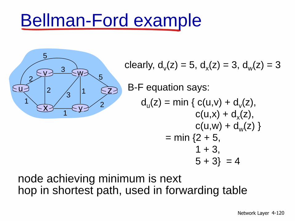
Bellman-Ford example
u
yx
wv
z
2
2
13
1
1
2
53
5
clearly, dv(z) = 5, dx(z) = 3, dw(z) = 3
du(z) = min { c(u,v) + dv(z),
c(u,x) + dx(z),
c(u,w) + dw(z) }
= min {2 + 5,
1 + 3,
5 + 3} = 4
node achieving minimum is nexthop in shortest path, used in forwarding table
B-F equation says:

Network Layer 4-121
Distance vector algorithm
Dx(y) = estimate of least cost from x to y x maintains distance vector Dx = [Dx(y): y є N ]
node x:
knows cost to each neighbor v: c(x,v)
maintains its neighbors’ distance vectors. For each neighbor v, x maintains Dv = [Dv(y): y є N ]
Network Layer 4-122
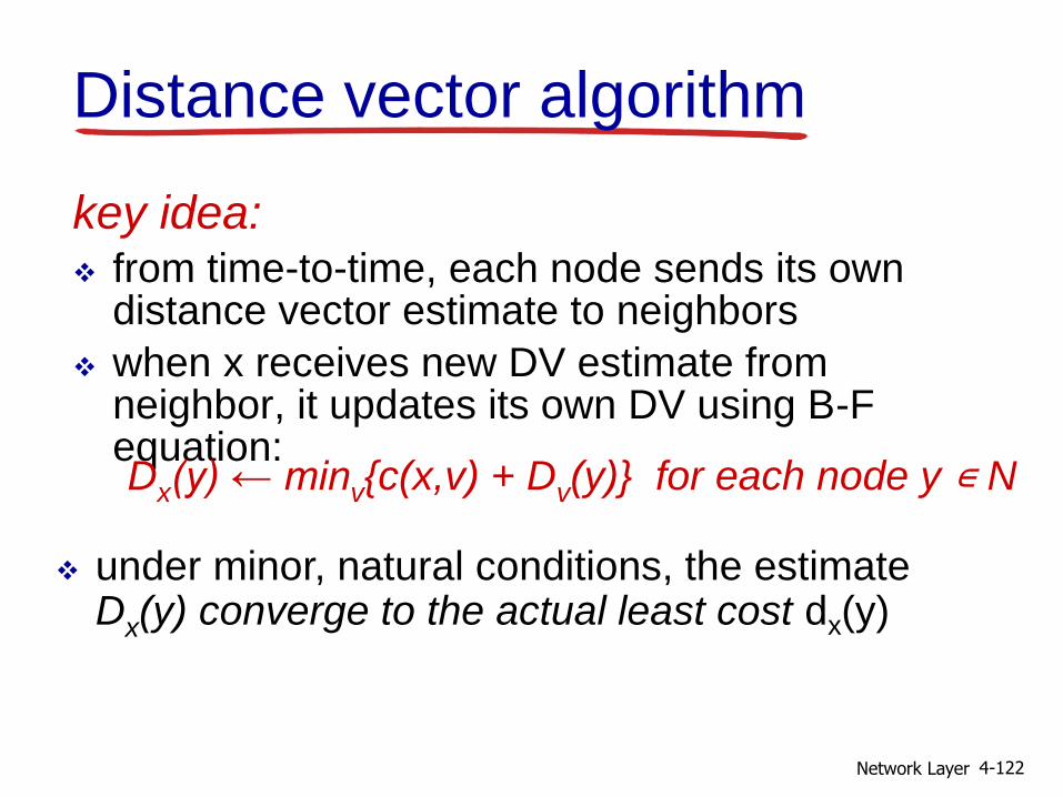
key idea: from time-to-time, each node sends its own
distance vector estimate to neighbors
when x receives new DV estimate from neighbor, it updates its own DV using B-F equation:Dx(y) ← minv{c(x,v) + Dv(y)} for each node y ∊ N
under minor, natural conditions, the estimate Dx(y) converge to the actual least cost dx(y)
Distance vector algorithm

Network Layer 4-123
iterative, asynchronous: each local iteration caused by:
local link cost change
DV update message from neighbor
distributed: each node notifies
neighbors only when its DV changes neighbors then notify
their neighbors if necessary
wait for (change in local link
cost or msg from neighbor)
recompute estimates
if DV to any dest has
changed, notify neighbors
each node:
Distance vector algorithm

Network Layer 4-124
x y z
x
y
z
0 2 7
∞ ∞ ∞
∞ ∞ ∞
fro
m
cost to
fro
mfr
om
x y z
x
y
z
0
x y z
x
y
z
∞ ∞
∞ ∞ ∞
cost to
x y z
x
y
z∞ ∞ ∞
7 1 0
cost to
∞
2 0 1
∞ ∞ ∞
2 0 1
7 1 0
time
x z
12
7
y
node xtable
Dx(y) = min{c(x,y) + Dy(y), c(x,z) + Dz(y)}
= min{2+0 , 7+1} = 2
Dx(z) = min{c(x,y) +
Dy(z), c(x,z) + Dz(z)}
= min{2+1 , 7+0} = 3
32
node ytable
node ztable
cost to
from

Network Layer 4-125
x y z
x
y
z
0 2 3
fro
m
cost to
x y z
x
y
z
0 2 7
fro
mcost to
x y z
x
y
z
0 2 3
fro
m
cost to
x y z
x
y
z
0 2 3
fro
mcost to
x y z
x
y
z
0 2 7
fro
m
cost to
2 0 1
7 1 0
2 0 1
3 1 0
2 0 1
3 1 0
2 0 1
3 1 0
2 0 1
3 1 0
time
x y z
x
y
z
0 2 7
∞ ∞ ∞
∞ ∞ ∞
fro
m
cost to
fro
mfr
om
x y z
x
y
z
0
x y z
x
y
z
∞ ∞
∞ ∞ ∞
cost to
x y z
x
y
z∞ ∞ ∞
7 1 0
cost to
∞
2 0 1
∞ ∞ ∞
2 0 1
7 1 0
time
x z
12
7
y
node xtable
Dx(y) = min{c(x,y) + Dy(y), c(x,z) + Dz(y)}
= min{2+0 , 7+1} = 2
Dx(z) = min{c(x,y) +
Dy(z), c(x,z) + Dz(z)}
= min{2+1 , 7+0} = 3
32
node ytable
node ztable
cost to
from

Network Layer 4-126
Distance vector: link cost changes
link cost changes: node detects local link cost
change
updates routing info, recalculates distance vector
if DV changes, notify neighbors“goodnews travelsfast”
x z
14
50
y1
t0 : y detects link-cost change, updates its DV, informs its
neighbors.
t1 : z receives update from y, updates its table, computes new
least cost to x , sends its neighbors its DV.
t2 : y receives z’s update, updates its distance table. y’s least costs
do not change, so y does not send a message to z.
Network Layer 4-127
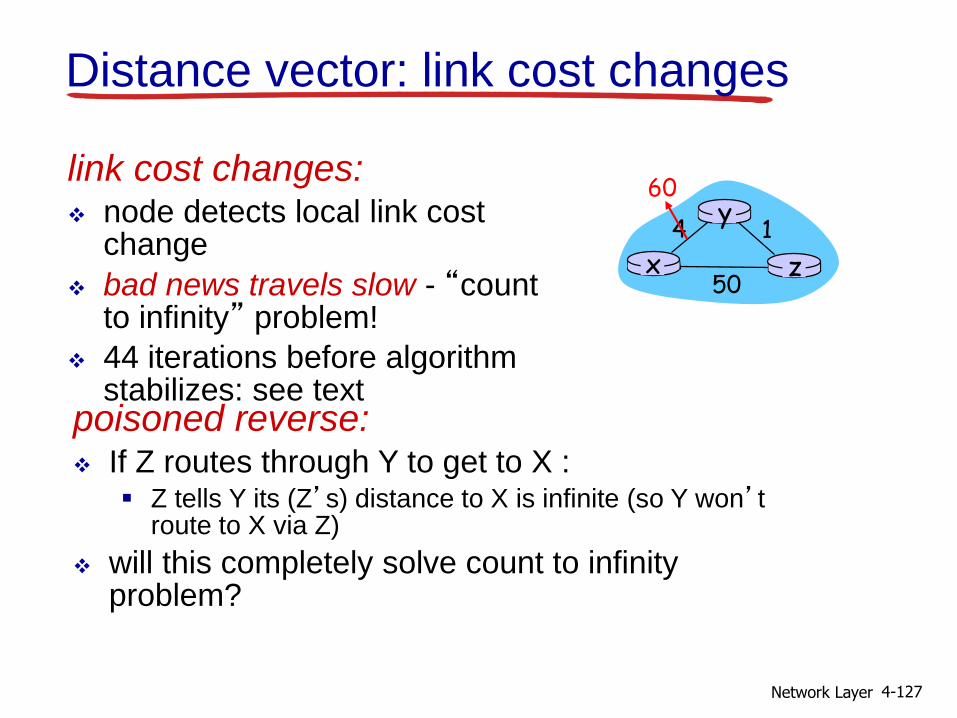
Distance vector: link cost changes
link cost changes: node detects local link cost
change
bad news travels slow - “count to infinity” problem!
44 iterations before algorithm stabilizes: see text
x z
14
50
y60
poisoned reverse: If Z routes through Y to get to X :
Z tells Y its (Z’s) distance to X is infinite (so Y won’t route to X via Z)
will this completely solve count to infinity problem?

Network Layer 4-128
Comparison of LS and DV algorithms
message complexity LS: with n nodes, E links,
O(nE) msgs sent
DV: exchange between neighbors only
convergence time varies
speed of convergence LS: O(n2) algorithm requires
O(nE) msgs
may have oscillations
DV: convergence time varies
may be routing loops
count-to-infinity problem
robustness: what happens if router malfunctions?
LS: node can advertise
incorrect link cost
each node computes only its own table
DV: DV node can advertise
incorrect path cost
each node’s table used by others
• error propagate thru network

Network Layer 4-129
4.1 introduction
4.2 virtual circuit and datagram networks
4.3 what’s inside a router
4.4 IP: Internet Protocol datagram format
IPv4 addressing
ICMP
IPv6
4.5 routing algorithms link state
distance vector
hierarchical routing
4.6 routing in the Internet RIP
OSPF
BGP
4.7 broadcast and multicast routing
Chapter 4: outline
Network Layer 4-130
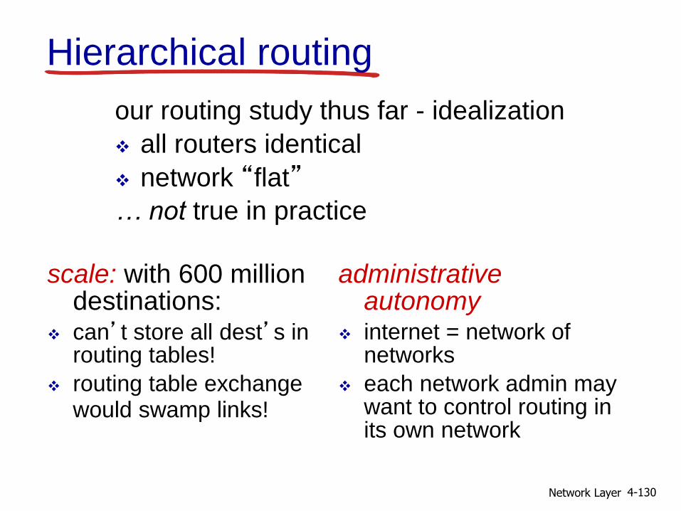
Hierarchical routing
scale: with 600 million destinations:
can’t store all dest’s in routing tables!
routing table exchange would swamp links!
administrative autonomy
internet = network of networks
each network admin may want to control routing in its own network
our routing study thus far - idealization
all routers identical
network “flat”
… not true in practice

Network Layer 4-131
aggregate routers into regions,“autonomous systems” (AS)
routers in same AS run same routing protocol “intra-AS” routing
protocol
routers in different AS can run different intra-AS routing protocol
gateway router: at “edge” of its own AS
has link to router in another AS
Hierarchical routing

Network Layer 4-132
3b
1d
3a
1c2a
AS3
AS1
AS21a
2c
2b
1b
Intra-AS
Routing
algorithm
Inter-AS
Routing
algorithm
Forwarding
table
3c
Interconnected ASes
forwarding table configured by both intra- and inter-AS routing algorithm
intra-AS sets entries for internal dests
inter-AS & intra-AS sets entries for external dests

Network Layer 4-133
Inter-AS tasks
suppose router in AS1 receives datagram destined outside of AS1:
router should forward packet to gateway router, but which one?
AS1 must:
1. learn which dests are reachable through AS2, which through AS3
2. propagate this reachability info to all routers in AS1
job of inter-AS routing!
AS3
AS2
3b
3c
3a
AS1
1c
1a1d
1b
2a2c
2b
other
networksother
networks

Network Layer 4-134
Example: setting forwarding table in router
1d
suppose AS1 learns (via inter-AS protocol) that subnet xreachable via AS3 (gateway 1c), but not via AS2
inter-AS protocol propagates reachability info to all internal routers
router 1d determines from intra-AS routing info that its interface I is on the least cost path to 1c
installs forwarding table entry (x,I)
AS3
AS2
3b
3c
3a
AS1
1c
1a1d
1b
2a2c
2b
other
networksother
networks
x

Network Layer 4-135
Example: choosing among multiple ASes
now suppose AS1 learns from inter-AS protocol that subnet x is reachable from AS3 and from AS2.
to configure forwarding table, router 1d must determine which gateway it should forward packets towards for dest x
this is also job of inter-AS routing protocol!
AS3
AS2
3b
3c
3a
AS1
1c
1a1d
1b
2a2c
2b
other
networksother
networks
x
?

Network Layer 4-136
learn from inter-AS
protocol that subnet
x is reachable via
multiple gateways
use routing info
from intra-AS
protocol to determine
costs of least-cost
paths to each
of the gateways
hot potato routing:
choose the gateway
that has the
smallest least cost
determine from
forwarding table the
interface I that leads
to least-cost gateway.
Enter (x,I) in
forwarding table
Example: choosing among multiple ASes
now suppose AS1 learns from inter-AS protocol that subnet x is reachable from AS3 and from AS2.
to configure forwarding table, router 1d must determine towards which gateway it should forward packets for dest x
this is also job of inter-AS routing protocol!
hot potato routing: send packet towards closest of two routers.
Network Layer 4-137
4.1 introduction
4.2 virtual circuit and datagram networks
4.3 what’s inside a router
4.4 IP: Internet Protocol datagram format
IPv4 addressing
ICMP
IPv6
4.5 routing algorithms link state
distance vector
hierarchical routing
4.6 routing in the Internet RIP
OSPF
BGP
4.7 broadcast and multicast routing
Chapter 4: outline

Network Layer 4-138
Intra-AS Routing
also known as interior gateway protocols (IGP)
most common intra-AS routing protocols:
RIP: Routing Information Protocol
OSPF: Open Shortest Path First
IGRP: Interior Gateway Routing Protocol (Cisco proprietary)

Network Layer 4-139
RIP ( Routing Information Protocol)
included in BSD-UNIX distribution in 1982
distance vector algorithm distance metric: # hops (max = 15 hops), each link has cost 1
DVs exchanged with neighbors every 30 sec in response message (aka advertisement)
each advertisement: list of up to 25 destination subnets (in IP addressing sense)
DC
BA
u v
w
x
yz
subnet hops
u 1
v 2
w 2
x 3
y 3
z 2
from router A to destination subnets:

Network Layer 4-140
RIP: example
destination subnet next router # hops to dest
w A 2
y B 2
z B 7
x -- 1…. …. ....
routing table in router D
w x y
z
A
C
D B

Network Layer 4-141
w x y
z
A
C
D B
destination subnet next router # hops to dest
w A 2
y B 2
z B 7
x -- 1…. …. ....
routing table in router D
A 5
dest next hopsw - 1x - 1z C 4…. … ...
A-to-D advertisement
RIP: example

Network Layer 4-142
RIP: link failure, recovery
if no advertisement heard after 180 sec --> neighbor/link declared dead routes via neighbor invalidated
new advertisements sent to neighbors
neighbors in turn send out new advertisements (if tables changed)
link failure info quickly (?) propagates to entire net
poison reverse used to prevent ping-pong loops (infinite distance = 16 hops)

Network Layer 4-143
RIP table processing
RIP routing tables managed by application-level process called route-d (daemon)
advertisements sent in UDP packets, periodically repeated
physical
link
network forwarding
(IP) table
transport
(UDP)
routed
physical
link
network
(IP)
transprt
(UDP)
routed
forwarding
table

144
Formato Pacore RIP
RIP utiliza UDP
4 bytes de header + 20 bytes para cada bloco de endereço (rota)
Pacote UDP limitação de 512 bytes, pode carregar no máximo 25 rotas

145
Formato Pacore RIPv1

Curso de Especialização em Redes de
Computadores – INF502
146
IGRP (Interior Gateway Routing Protocol)
Proprietário da CISCO; sucessor do RIP (anos 80)
Vetor de Distâncias, como RIP
Diversas métricas de custo (retardo, largura de banda, confiabilidade, carga, etc)
usa TCP para trocar mudanças de rotas
Roteamento sem ciclos via Distributed Updating Algorithm (DUAL) baseado em computação difusa

147
Métricas de Composta
(E) IGRP utiliza métrica composta com parcelas relativas a: atraso, banda passante, carga na rede e confiabilidade compesos diferentes
148
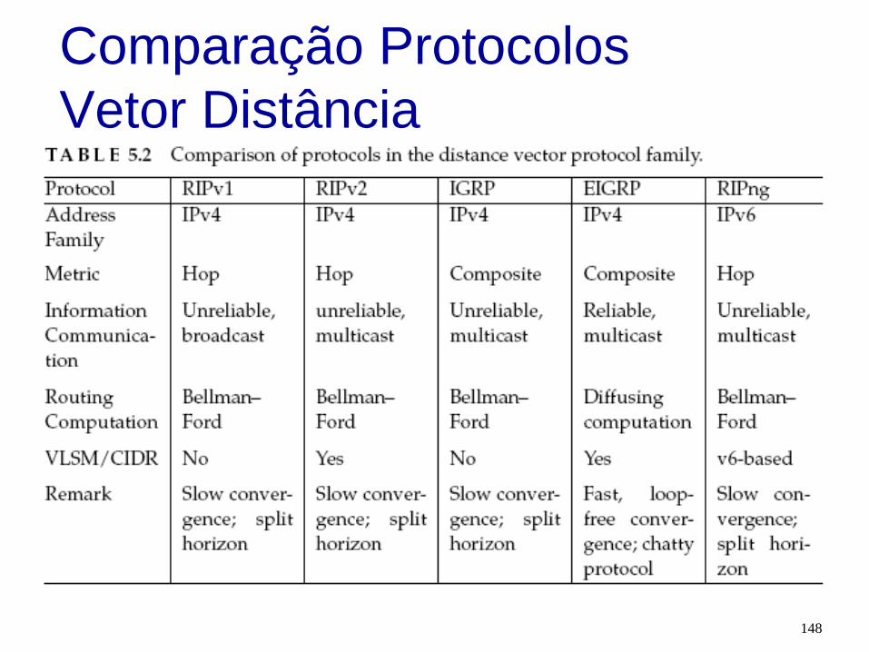
Comparação Protocolos
Vetor Distância

Network Layer 4-149
OSPF (Open Shortest Path First)
“open”: publicly available
uses link state algorithm LS packet dissemination
topology map at each node
route computation using Dijkstra’s algorithm
OSPF advertisement carries one entry per neighbor
advertisements flooded to entire AS carried in OSPF messages directly over IP (rather
than TCP or UDP
IS-IS routing protocol: nearly identical to OSPF

Network Layer 4-150
OSPF “advanced” features (not in
RIP) security: all OSPF messages authenticated (to
prevent malicious intrusion)
multiple same-cost paths allowed (only one path in RIP)
for each link, multiple cost metrics for different TOS (e.g., satellite link cost set “low” for best effort ToS; high for real time ToS)
integrated uni- and multicast support:
Multicast OSPF (MOSPF) uses same topology data base as OSPF
hierarchical OSPF in large domains.

Network Layer 4-151
Hierarchical OSPF
boundary router
backbone router
area 1
area 2
area 3
backbone
areaborderrouters
internalrouters

Network Layer 4-152
two-level hierarchy: local area, backbone.
link-state advertisements only in area
each nodes has detailed area topology; only know direction (shortest path) to nets in other areas.
area border routers: “summarize” distances to nets in own area, advertise to other Area Border routers.
backbone routers: run OSPF routing limited to backbone.
boundary routers: connect to other AS’s.
Hierarchical
OSPF

Chapter 4: Internet Protocol Layer 153
N1
N2
N3
N4
N8N6
N7
N11
N9
N10
N12
N15
N12
N13
N14
Internal
router
Area border
router
H1
RT1
RT2
RT4
RT3
RT5
RT6
RT10
RT11
RT9
RT12
RT7
RT8
3
3
1
1
1
1
1
1
1 1
1
4
2
2
2
2
8
8
8
66
7 6
6
88
8
9
1
10
3
7
5
Ia
Ib
Area 1
Area 2
Area 3
Stub
AS boundary
router

Chapter 4: Internet Protocol Layer 154
OSPF Example: Intra-area Informação sobre a área difundidada por RT3
and RT4 para o backbone.
Network Cost advertised by RT3 Cost advertised by RT4
N1 4 4
N2 4 4
N3 1 1
N4 2 3
N1
N2
N3
N4
RT1
RT2
RT4
RT3
3
3
1
1
1
1
2
Area 1

Chapter 4: Internet Protocol Layer 155
Tabela de roteamento - OSPF
Tabela do roteador RT4
Destination Path Type Cost Next Hop
N1 intra-area 4 RT1
N2 intra-area 4 RT2
N3 intra-area 1 direct
N4 intra-area 3 RT3
N6 Inter-area 15 RT5
N7 inter-area 19 RT5
N8 Inter-area 18 RT5
N9-N11 inter-area 36 RT5
N12 Type 1 external 16 RT5
N13 Type 1 external 16 RT5
N14 Type 1 external 16 RT5
N15 Type 1 external 23 RT5

Tipos de Mensagem OSPF
Curso de Especialização em Redes de
Computadores – INF502
156
Type Description
1 Hello
2 Database Description
3 Request
4 Update
5 Acknowledgment

Mensagens LS
Curso de Especialização em Redes de
Computadores – INF502
157
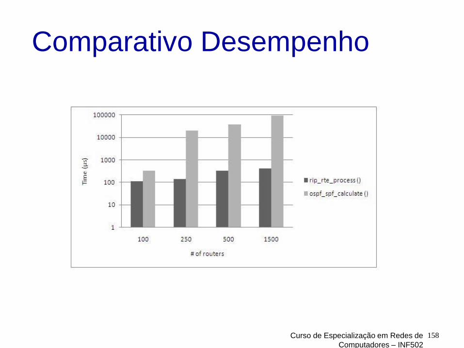
Comparativo Desempenho
Curso de Especialização em Redes de
Computadores – INF502
158
Network Layer 4-159
Internet inter-AS routing: BGP
BGP (Border Gateway Protocol): the de facto inter-domain routing protocol “glue that holds the Internet together”
BGP provides each AS a means to:
eBGP: obtain subnet reachability information from neighboring ASs.
iBGP: propagate reachability information to all AS-internal routers.
determine “good” routes to other networks based on reachability information and policy.
allows subnet to advertise its existence to rest of Internet: “I am here”

Network Layer 4-160
BGP basics
when AS3 advertises a prefix to AS1: AS3 promises it will forward datagrams towards that prefix
AS3 can aggregate prefixes in its advertisement
AS3
AS2
3b
3c
3a
AS1
1c
1a1d
1b
2a2c
2b
other
networksother
networks
BGP session: two BGP routers (“peers”) exchange BGP messages: advertising paths to different destination network prefixes (“path
vector” protocol)
exchanged over semi-permanent TCP connections
BGP message

iBGP e eBGP
Curso de Especialização em Redes de
Computadores – INF502
161

Network Layer 4-162
BGP basics: distributing path
information
AS3
AS2
3b3a
AS1
1c
1a1d
1b
2a2c
2b
other
networksother
networks
using eBGP session between 3a and 1c, AS3 sends prefix reachability info to AS1. 1c can then use iBGP do distribute new prefix info to all
routers in AS1
1b can then re-advertise new reachability info to AS2 over 1b-to-2a eBGP session
when router learns of new prefix, it creates entry for prefix in its forwarding table.
eBGP session
iBGP session

Network Layer 4-163
Path attributes and BGP
routes advertised prefix includes BGP attributes
prefix + attributes = “route”
two important attributes: AS-PATH: contains ASs through which prefix
advertisement has passed: e.g., AS 67, AS 17
NEXT-HOP: indicates specific internal-AS router to next-hop AS. (may be multiple links from current AS to next-hop-AS)
gateway router receiving route advertisement uses import policy to accept/decline e.g., never route through AS x
policy-based routing
Network Layer 4-164
BGP route selection
router may learn about more than 1 route to destination AS, selects route based on:
1. local preference value attribute: policy decision
2. shortest AS-PATH
3. closest NEXT-HOP router: hot potato routing
4. additional criteria

Network Layer 4-165
BGP messages
BGP messages exchanged between peers over TCP connection
BGP messages:
OPEN: opens TCP connection to peer and authenticates sender
UPDATE: advertises new path (or withdraws old)
KEEPALIVE: keeps connection alive in absence of UPDATES; also ACKs OPEN request
NOTIFICATION: reports errors in previous msg; also used to close connection

Atributo AS_PATH
166

Agregação de Rotas
167

Seleção de Rotas - BGP
Um roteador pode aprender mais do que 1 rota para o mesmo prefixo. O roteador deve selecionar uma rota
Regras de eliminação:
Atributo de valor de preferência local: decisão de política
AS-PATH (caminho) mais curto
Roteador do NEXT-HOP (próximo salto) maispróximo: roteamento da “batata quente”
Critérios adicionais
Curso de Especialização em Redes de
Computadores – INF502
168

Selação de Rotas
Curso de Especialização em Redes de
Computadores – INF502
169
Network Next Hop LOCAL_
PREF Weight Best? PATH Origin
139.175.56.165 0 N 4780,9739 IGP
140.123.231.103 0 N 9918,4780,9739 IGP 61.13.0.0/16
140.123.231.100 0 0 Y 9739 IGP
139.175.56.165 0 Y 4780,9277,17577 IGP 61.251.128.0/20
140.123.231.103 0 N 9918,4780,9277,17577 IGP
211.73.128.0/19 210.241.222.62 0 Y 9674 IGP
139.175.56.165 0 N 4780,9919 IGP
140.123.231.103 0 N 9918,4780,9919 IGP 218.32.0.0/17
140.123.231.106 0 Y 9919 IGP
139.175.56.165 0 N 4780,9919 IGP
140.123.231.103 0 N 9918,4780,9919 IGP 218.32.128.0/17
140.123.231.106 0 Y 9919 IGP

Network Layer 4-170
BGP routing policy
A,B,C are provider networks
X,W,Y are customer (of provider networks)
X is dual-homed: attached to two networks
X does not want to route from B via X to C
.. so X will not advertise to B a route to C
A
B
C
WX
Y
legend:
customer network:
providernetwork

Network Layer 4-171
BGP routing policy (2)
A advertises path AW to B
B advertises path BAW to X
Should B advertise path BAW to C? No way! B gets no “revenue” for routing CBAW since neither W
nor C are B’s customers
B wants to force C to route to w via A
B wants to route only to/from its customers!
A
B
C
WX
Y
legend:
customer network:
providernetwork
Network Layer 4-172
Why different Intra-, Inter-AS routing
?policy: inter-AS: admin wants control over how its traffic
routed, who routes through its net.
intra-AS: single admin, so no policy decisions needed
scale: hierarchical routing saves table size, reduced
update traffic
performance:
intra-AS: can focus on performance
inter-AS: policy may dominate over performance

Network Layer 4-173
4.1 introduction
4.2 virtual circuit and datagram networks
4.3 what’s inside a router
4.4 IP: Internet Protocol datagram format
IPv4 addressing
ICMP
IPv6
4.5 routing algorithms link state
distance vector
hierarchical routing
4.6 routing in the Internet RIP
OSPF
BGP
4.7 broadcast and multicast routing
Chapter 4: outline

Network Layer 4-174
R1
R2
R3 R4
source
duplication
R1
R2
R3 R4
in-network
duplication
duplicate
creation/transmissionduplicate
duplicate
Broadcast routing deliver packets from source to all other nodes
source duplication is inefficient:
source duplication: how does source determine recipient addresses?

Network Layer 4-175
In-network duplication
flooding: when node receives broadcast packet, sends copy to all neighbors problems: cycles & broadcast storm
controlled flooding: node only broadcasts pkt if it hasn’t broadcast same packet before node keeps track of packet ids already
broadacsted
or reverse path forwarding (RPF): only forward packet if it arrived on shortest path between node and source
spanning tree: no redundant packets received by any node

Network Layer 4-176
A
B
G
D
E
c
F
A
B
G
D
E
c
F
(a) broadcast initiated at A (b) broadcast initiated at D
Spanning tree
first construct a spanning tree
nodes then forward/make copies only along spanning tree

Network Layer 4-177
A
B
G
D
E
c
F1
2
3
4
5
(a) stepwise construction of
spanning tree (center: E)
A
B
G
D
E
c
F
(b) constructed spanning
tree
Spanning tree: creation
center node
each node sends unicast join message to center node message forwarded until it arrives at a node
already belonging to spanning tree

Network Layer 4-178
Multicast routing: problem statement
goal: find a tree (or trees) connecting routers having local mcast group members
tree: not all paths between routers used
shared-tree: same tree used by all group members
shared tree source-based trees
group member
not group member
routerwith agroup member
routerwithoutgroup member
legend
source-based: different tree from each sender to rcvrs

Curso de Especialização em Redes de
Computadores – INF502179
Multicast: um emissor para vários receptoresMulticast: envia datagramas para múltiplos receptores com uma única operação de transmissão
analogia: um professor para vários estudantes, alimentação de dados: cotações da bolsa de valores;
atualização de cache WWW;
ambientes virtuais interativos distribuídos, etc.
Questão: como garantir multicast?
Multicast via unicastFonte envia N datagrams unicast, um para cada um dos N receptores
Receptores multicast (vermelho)
Não é um receptor multicast
Roteadoresencaminham datagramas unicast

Curso de Especialização em Redes de
Computadores – INF502180
Desafios do Suporte a Multicast na Camada de Rede
Como identificar os receptores de um datagrama multicast?
Como endereçar um datagrama a ser enviado para estes receptores.
Não dá para incluir o endereço IP de cada um dos destinos no cabeçalho do datagrama!
Não funciona para um grande número de receptores;
requer que o transmissor conheça a identidade e endereços de cada um dos destinatários.
Endereço indireto: é usado um identificador único para um grupo de usuários.
Grupo Multicast associado a um endereço classe D.

Curso de Especialização em Redes de
Computadores – INF502181
Modelo de Serviço Multicast da Internet
Conceito de grupo Multicast: uso de indireção
Hosts endereçam os datagramas IP para o grupo multicast
Roteadores encaminham os datagramas multicast para os hosts que se “juntaram” ao grupo multicast

Curso de Especialização em Redes de
Computadores – INF502182
Grupos Multicast
Endereços classe D na Internet são reservados para multicast:
Semântica de grupo de hosts:
qualquer um pode se “juntar” (receber) a um grupo multicast
qualquer um pode enviar para um grupo multicast
nenhuma identificação na camada de rede para os hosts membros
necessário: infraestrutura para enviar datagramas multicast para todos os hosts que se juntaram ao grupo

Curso de Especialização em Redes de
Computadores – INF502183
Grupos Multicast: questões
Como um grupo é iniciado e como ele é encerrado?
Como é escolhido o endereço do grupo?
Como são adicionados novos hosts ao grupo?
Qualquer um pode fazer parte (ativa) do grupo ou a participação é restrita?
Caso seja restrita, quem determina a restrição?
Os membros do grupo têm conhecimento das identidades dos demais membros do grupo na camada de rede?
Como os roteadores interoperam para entregar um datagrama multicast a todos os membros do grupo?
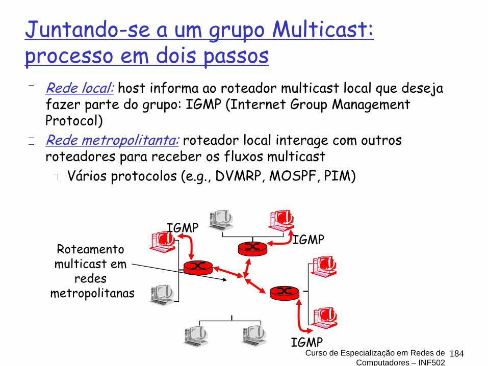
Curso de Especialização em Redes de
Computadores – INF502184
Juntando-se a um grupo Multicast: processo em dois passos
Rede local: host informa ao roteador multicast local que deseja fazer parte do grupo: IGMP (Internet Group Management Protocol)
Rede metropolitanta: roteador local interage com outros roteadores para receber os fluxos multicast
Vários protocolos (e.g., DVMRP, MOSPF, PIM)
IGMPIGMP
IGMP
Roteamento multicast em
redes metropolitanas

Curso de Especialização em Redes de
Computadores – INF502185
IGMP: Internet Group Management Protocol – RFC 2236
Opera entre o host e o roteador ao qual ele está conectado diretamente:
host: envia notificação IGMP quando a aplicação se junta a um grupo multicast
IP_ADD_MEMBERSHIP opção de socket
host não necessita fazer uma notificação quando sai de um grupo
roteador: envia requisição IGMP a intervalos regulares
host pertencente a um grupo multicast deve responder a requisição
query report

Curso de Especialização em Redes de
Computadores – INF502186
O Protocolo IGMP
O IGMP fornece meios para que o host informe ao roteador ao qual está conectado que uma aplicação deseja ser incluída em um grupo multicast.
Apesar do nome ele não é um protocolo que opera entre todos os hosts que tenham formado um grupo multicast.
É necessário um outro protocolo para coordenar os roteadores multicast, de modo que os datagramas multicast sejam roteados até seus destinos: algoritmos de roteamento multicast da camada de rede. Ex: PIM, DVMRP e MOSPF.

Curso de Especialização em Redes de
Computadores – INF502187
Tipos de Mensagens IGMP v2
Tipos das Mensagens IGMP
Enviada por
Finalidade
Consulta sobre participação em grupos:geral
Roteador Consultar quais os grupos multicast em que os hosts associados estão incluídos.
Consulta sobre participação em grupos:específica
Roteador Consultar se os hosts associados estão incluídos em um grupos multicast específico.
Relato de participação
Host Relatar que o host quer ser ou já está incluído num dado grupo multicast.
Saída de grupo Host Relata que está saindo de um determinado grupo multicast.

Curso de Especialização em Redes de
Computadores – INF502188
Consulta sobre participação e
resposta
As mensagens de relato também podem ser enviadas por iniciativa do host quando uma aplicação deseja ser incluída num grupo multicast.
Para o roteador não importa quais nem quantos hosts fazem parte do mesmo grupo multicast.

Curso de Especialização em Redes de
Computadores – INF502189
Formato das Mensagens
IGMPUsado para suprimir relatos duplicados: cada host espera um tempoaleatório entre 0 e este valor máximo antes de enviar o seu relato. Se antes disto este host escutar o relato de algum outro host, ele descarta a sua mensagem.
Encapsuladas em datagramas IP com número de protocolo 2.

Curso de Especialização em Redes de
Computadores – INF502190
Modelo do Serviço Multicast
da Internet Qualquer host pode ser incluído no grupo
multicast na camada de rede. O host simplesmente envia uma mensagem IGMP
de relato de participação para o roteador ao qual está conectado.
Em pouco tempo o roteador agindo em conjunto com os demais roteadores começará a entregar datagramas multicast para este host.
Portanto, a adesão a um grupo é uma iniciativa do receptor.

Network Layer 4-191
Approaches for building mcast
treesapproaches:
source-based tree: one tree per source shortest path trees
reverse path forwarding
group-shared tree: group uses one tree minimal spanning (Steiner)
center-based trees
…we first look at basic approaches, then specific protocols
adopting these approaches

Network Layer 4-192
Shortest path tree
mcast forwarding tree: tree of shortest path routes from source to all receivers Dijkstra’s algorithm
i
router with attached
group member
router with no attached
group member
link used for forwarding,
i indicates order link
added by algorithm
LEGEND
R1
R2
R3
R4
R5
R6 R7
2
1
6
3 4
5
s: source

Network Layer 4-193
Reverse path forwarding
if (mcast datagram received on incoming link on shortest path back to center)
then flood datagram onto all outgoing links
else ignore datagram
rely on router’s knowledge of unicast shortest
path from it to sender
each router has simple forwarding behavior:

Network Layer 4-194
Reverse path forwarding:
example
result is a source-specific reverse SPT
may be a bad choice with asymmetric links
router with attached
group member
router with no attached
group member
datagram will be forwarded
LEGENDR1
R2
R3
R4
R5
R6 R7
s: source
datagram will not be
forwarded

Network Layer 4-195
Reverse path forwarding:
pruning forwarding tree contains subtrees with no mcast group
members
no need to forward datagrams down subtree
“prune” msgs sent upstream by router with no downstream group members
router with attached
group member
router with no attached
group member
prune message
LEGEND
links with multicast
forwarding
P
R1
R2
R3
R4
R5
R6
R7
s: source
P
P

Network Layer 4-196
Shared-tree: steiner tree
steiner tree: minimum cost tree connecting all routers with attached group members
problem is NP-complete
excellent heuristics exists
not used in practice: computational complexity
information about entire network needed
monolithic: rerun whenever a router needs to join/leave

Network Layer 4-197
Center-based trees
single delivery tree shared by all
one router identified as “center” of tree
to join: edge router sends unicast join-msg addressed to
center router
join-msg “processed” by intermediate routers and forwarded towards center
join-msg either hits existing tree branch for this center, or arrives at center
path taken by join-msg becomes new branch of tree for this router

Network Layer 4-198
Center-based trees: example
suppose R6 chosen as center:
router with attached
group member
router with no attached
group member
path order in which join
messages generated
LEGEND
21
3
1
R1
R2
R3
R4
R5
R6
R7

Network Layer 4-199
Internet Multicasting Routing: DVMRP
DVMRP: distance vector multicast routing protocol, RFC1075
flood and prune: reverse path forwarding, source-based tree RPF tree based on DVMRP’s own routing tables
constructed by communicating DVMRP routers
no assumptions about underlying unicast
initial datagram to mcast group flooded everywhere via RPF
routers not wanting group: send upstream prune msgs

Network Layer 4-200
DVMRP: continued…
soft state: DVMRP router periodically (1 min.) “forgets” branches are pruned: mcast data again flows down unpruned branch
downstream router: reprune or else continue to receive data
routers can quickly regraft to tree following IGMP join at leaf
odds and ends commonly implemented in commercial router

Network Layer 4-201
Tunneling
Q: how to connect “islands” of multicast routers in a “sea” of unicast routers?
mcast datagram encapsulated inside “normal” (non-multicast-addressed) datagram
normal IP datagram sent thru “tunnel” via regular IP unicast to receiving mcast router (recall IPv6 inside IPv4 tunneling)
receiving mcast router unencapsulates to get mcast datagram
physical topology logical topology

Network Layer 4-202
PIM: Protocol Independent Multicast
not dependent on any specific underlying unicast routing algorithm (works with all)
two different multicast distribution scenarios :
dense:
group members
densely packed, in
“close” proximity.
bandwidth more
plentiful
sparse:
# networks with group
members small wrt #
interconnected networks
group members “widely
dispersed”
bandwidth not plentiful

Network Layer 4-203
Consequences of sparse-dense
dichotomy:
dense group membership by
routers assumed until routers explicitly prune
data-driven construction on mcast tree (e.g., RPF)
bandwidth and non-group-router processing profligate
sparse:
no membership until routers explicitly join
receiver- drivenconstruction of mcast tree (e.g., center-based)
bandwidth and non-group-router processing conservative

Network Layer 4-204
PIM- dense mode
flood-and-prune RPF: similar to DVMRP but…
underlying unicast protocol provides RPF info for incoming datagram
less complicated (less efficient) downstream flood than DVMRP reduces reliance on underlying routing algorithm
has protocol mechanism for router to detect it is a leaf-node router

Network Layer 4-205
PIM - sparse
mode center-based approach
router sends join msg to rendezvous point (RP)
intermediate routers update state and forward join
after joining via RP, router can switch to source-specific tree
increased performance: less concentration, shorter paths
all data multicast
from rendezvous
point
rendezvous
point
join
join
join
R1
R2
R3
R4
R5
R6
R7

Network Layer 4-206
sender(s): unicast data to RP,
which distributes down RP-rooted tree
RP can extend mcast tree upstream to source
RP can send stopmsg if no attached receivers “no one is listening!”
all data multicast
from rendezvous
point
rendezvous
point
join
join
join
R1
R2
R3
R4
R5
R6
R7
PIM - sparse
mode

Network Layer 4-207
4.1 introduction
4.2 virtual circuit and datagram networks
4.3 what’s inside a router
4.4 IP: Internet Protocol datagram format, IPv4
addressing, ICMP, IPv6
4.5 routing algorithms link state, distance
vector, hierarchical routing
4.6 routing in the Internet RIP, OSPF, BGP
4.7 broadcast and multicast routing
Chapter 4: done!
understand principles behind network layer services:
network layer service models, forwarding versus routing how a router works, routing (path selection), broadcast, multicast
instantiation, implementation in the Internet
Recommended