Chapter-4: Kani’s Method
By Prof. A.B.Harwalkar
PDA College of Engineering,Gulbarga
VTU – EDUSAT Programme – 7Class: B.E. V Sem (Civil Engineering) Sub: Structural Analysis – II (CV51)
Session on 08.10.2007KANI’S METHOD FOR ANALYSIS OF INDETERMINATE
STRUCTURES:By A.B.Harwalkar
P.D.A.College of Engg Gulbarga
This method was developed by Dr. Gasper Kani of Germany in 1947. Thismethod offers an iterative scheme for applying slope deflection method. We shall nowsee the application of Kani’s method for different cases.
I. Beams with no translation of joints:
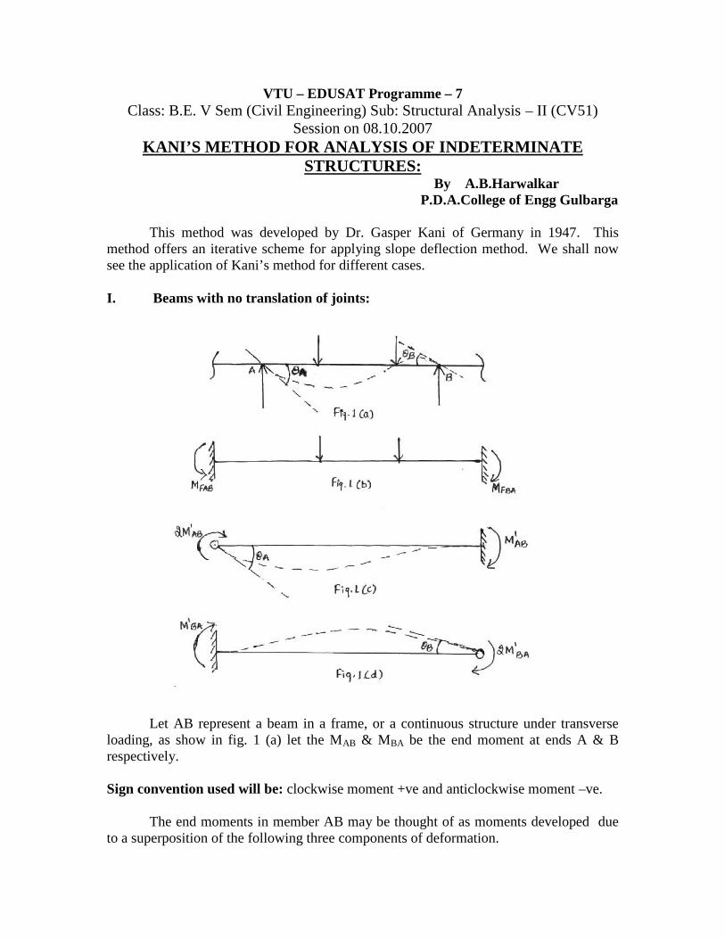
Let AB represent a beam in a frame, or a continuous structure under transverseloading, as show in fig. 1 (a) let the MAB & MBA be the end moment at ends A & Brespectively.
Sign convention used will be: clockwise moment +ve and anticlockwise moment –ve.
The end moments in member AB may be thought of as moments developed dueto a superposition of the following three components of deformation.
1. The member ‘AB’ is regarded as completely fixed. (Fig. 1 b). The fixed endmoments for this condition are written as MFAB & MFBA, at ends A & B respectively.
2. The end A only is rotated through an angle A by a moment 2 'ABM inducing a
moment 'ABM at fixed end B.
3. Next rotating the end B only through an angle B by moment 'BAM2 while keeping
end ‘A’ as fixed. This induces a moment 'BAM at end A.
Thus the final moment MAB & MBA can be expressed as super position of threemoments
MAB = MFAB + 'BA
'AB MM2
MBA = MFBA + 'BAM2 + '
ABM
For member AB we refer end ‘A’ as near end and end ‘B’ as far end. Similarlywhen we refer to moment MBA, B is referred as near end and end A as far end.
Hence above equations can be stated as follows. The moment at the near end of amember is the algebraic sum of (a) fixed end moment at near end. (b) Twice the rotationmoment of the near end (c) rotation moment of the far end.
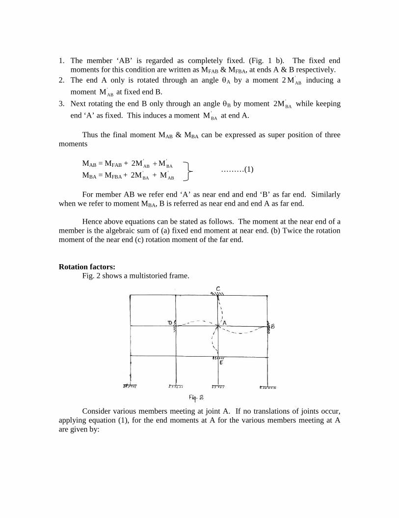
Rotation factors:Fig. 2 shows a multistoried frame.
Consider various members meeting at joint A. If no translations of joints occur,applying equation (1), for the end moments at A for the various members meeting at Aare given by:
………(1)
MAB = MFAB + 'BA
'AB MM2
MAC = MFAC + 'ACM2 + '
CAM
MAD = MFAD + 2 'ADM + '
DAM
MAE = MFAE + 'AEM2 + '
EAM
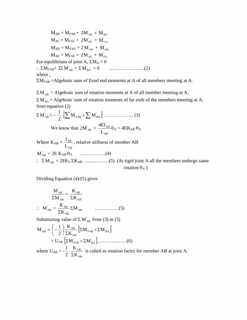
For equilibrium of joint A, MA = 0MFAB+ 2 '
ABM + 'BAM = 0 ………………….(2)
where ,MFAB =Algebraic sum of fixed end moments at A of all members meeting at A.
'ABM = Algebraic sum of rotation moments at A of all member meeting at A.
'BAM = Algebraic sum of rotation moments of far ends of the members meeting at A.
from equation (2)
'ABM =
2
1 'BAFAB MM ……………… (3)
We know that 'ABM2 =
AB
AB
L
EI4A = 4EKAB A
Where KAB =AB
AB
L
I, relative stiffness of member AB
'ABM = 2E KAB A …………….(4)
'ABM = 2EA KAB …………….(5) (At rigid joint A all the members undergo same
rotation A )
Dividing Equation (4)/(5) gives
'AB
'AB
M
M
=
AB
AB
K
K
'ABM = '
ABAB
AB MK
K
……………(5)
Substituting value of 'ABM from (3) in (5)
'BAFAB
AB
AB'AB MM
K
K
2
1M
= UAB 'BAFAB MM ………………(6)
where UAB = -2
1
AB
AB
K
K
is called as rotation factor for member AB at joint A.
Analysis Method:In equation (6) MFAB is a known quantity. To start with the far end rotation
moments 'BAM are not known and hence they may be taken as zero. By a similar
approximation the rotation moments at other joints are also determined. With theapproximate values of rotation moments computed, it is possible to again determine amore correct value of the rotation moment at A from member AB using equation (6).
The process is carried out for sufficient number of cycles until the desired degreeof accuracy is achieved.
The final end moments are calculated using equation (1).
VTU – EDUSAT Programme – 7Class: B.E. V Sem (Civil Engineering) Sub: Structural Analysis – II (CV51)
Session on 09.10.2007KANI’S METHOD FOR ANALYSIS OF INDETERMINATE
STRUCTURES (CONTD.)By A.B.Harwalkar
P.D.A.College of Engg Gulbarga
Kani’s method for beams without translation of joints, is illustrated in following
examples:
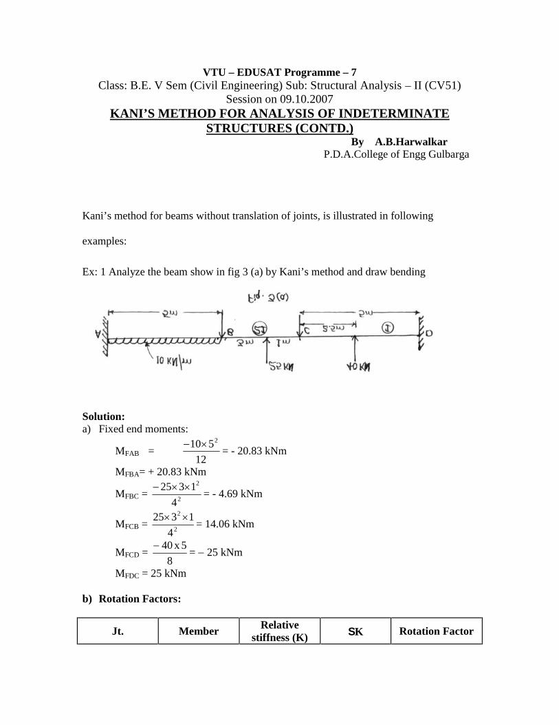
Ex: 1 Analyze the beam show in fig 3 (a) by Kani’s method and draw bending
moment diagram
Solution:a) Fixed end moments:
MFAB =12
510 2= - 20.83 kNm
MFBA= + 20.83 kNm
MFBC =2
2
4
1325 = - 4.69 kNm
MFCB =2
2
4
1325 = 14.06 kNm
MFCD =8
5x40= 25 kNm
MFDC = 25 kNm
b) Rotation Factors:
Jt. Member Relativestiffness (K) K Rotation Factor
= -2
1xKK
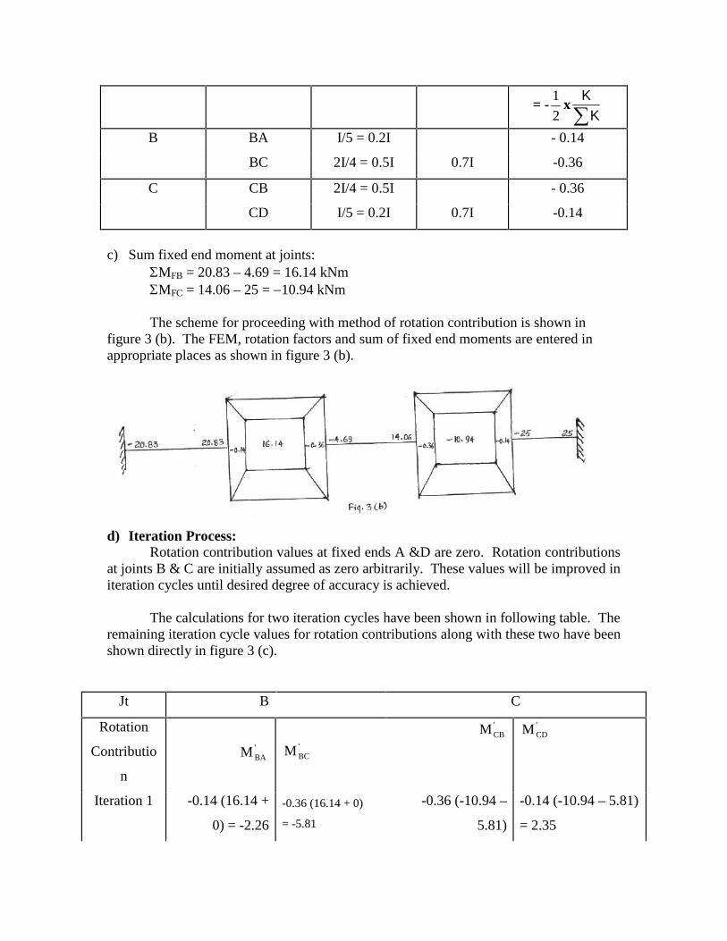
B BA I/5 = 0.2I - 0.14
BC 2I/4 = 0.5I 0.7I -0.36
C CB 2I/4 = 0.5I - 0.36
CD I/5 = 0.2I 0.7I -0.14
c) Sum fixed end moment at joints:MFB = 20.83 – 4.69 = 16.14 kNmMFC = 14.06 – 25 = 10.94 kNm
The scheme for proceeding with method of rotation contribution is shown infigure 3 (b). The FEM, rotation factors and sum of fixed end moments are entered inappropriate places as shown in figure 3 (b).
d) Iteration Process:Rotation contribution values at fixed ends A &D are zero. Rotation contributions
at joints B & C are initially assumed as zero arbitrarily. These values will be improved initeration cycles until desired degree of accuracy is achieved.
The calculations for two iteration cycles have been shown in following table. Theremaining iteration cycle values for rotation contributions along with these two have beenshown directly in figure 3 (c).
Jt B C
Rotation
Contributio
n
'BAM '
BCM
'CBM '
CDM
Iteration 1 -0.14 (16.14 +
0) = -2.26
-0.36 (16.14 + 0)
= -5.81
-0.36 (-10.94 –
5.81)
-0.14 (-10.94 – 5.81)
= 2.35
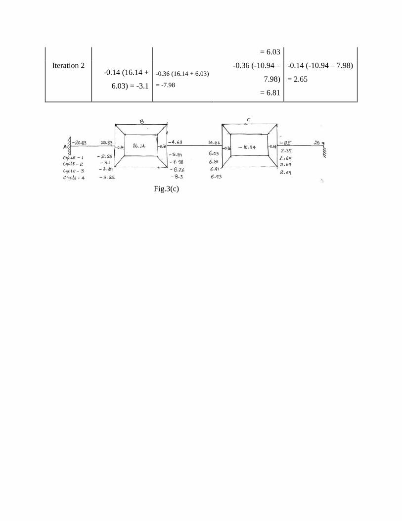
= 6.03
Iteration 2-0.14 (16.14 +
6.03) = -3.1
-0.36 (16.14 + 6.03)
= -7.98
-0.36 (-10.94 –
7.98)
= 6.81
-0.14 (-10.94 – 7.98)
= 2.65
Fig.3(c)
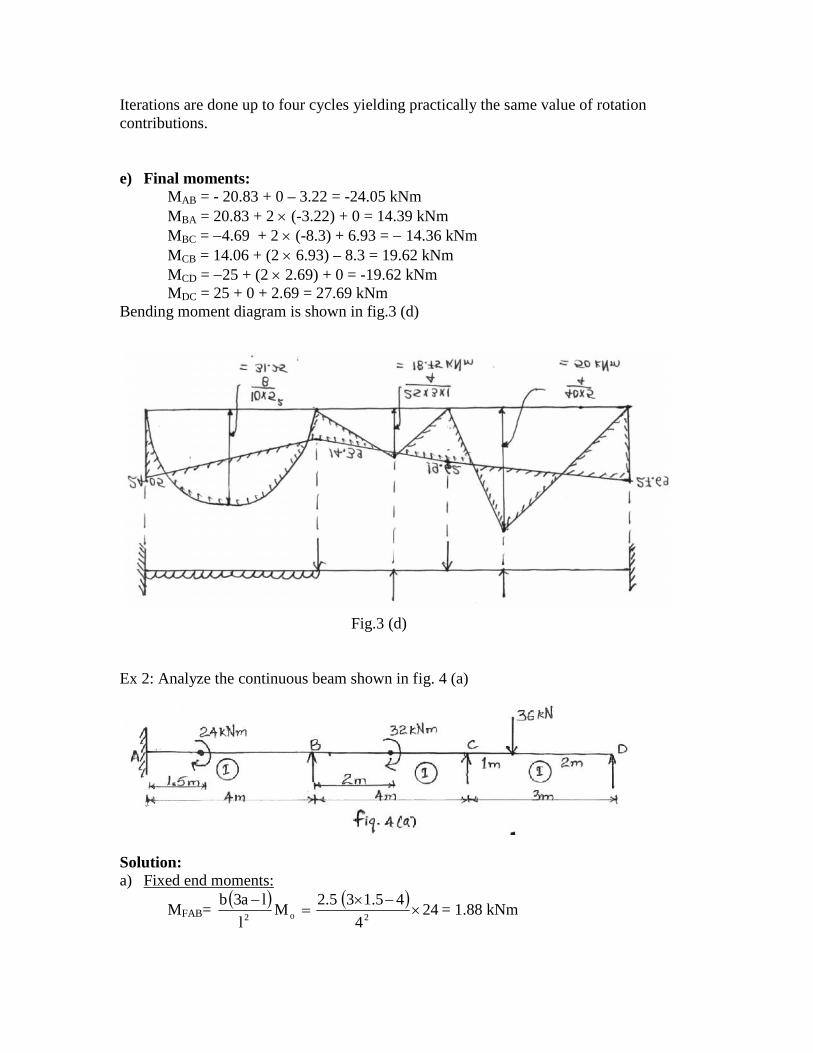
Iterations are done up to four cycles yielding practically the same value of rotationcontributions.
e) Final moments:MAB = - 20.83 + 0 – 3.22 = -24.05 kNmMBA = 20.83 + 2 (-3.22) + 0 = 14.39 kNmMBC = 4.69 + 2 (-8.3) + 6.93 = 14.36 kNmMCB = 14.06 + (2 6.93) – 8.3 = 19.62 kNmMCD = 25 + (2 2.69) + 0 = -19.62 kNmMDC = 25 + 0 + 2.69 = 27.69 kNm
Bending moment diagram is shown in fig.3 (d)
Fig.3 (d)
Ex 2: Analyze the continuous beam shown in fig. 4 (a)
Solution:a) Fixed end moments:
MFAB=
244
45.135.2M
l
la3b2o2
= 1.88 kNm
MFBA =
88.7244
45.235.1M
l
lb3a2o2
kNm
MFBC =4
M o =4
32= 8 kNm
MFCB =4
M o = 8 kNm
MFCD = 2
2
3
2136 = -16 kNm
MFDC =2
2
3
2136 = 8 kNm
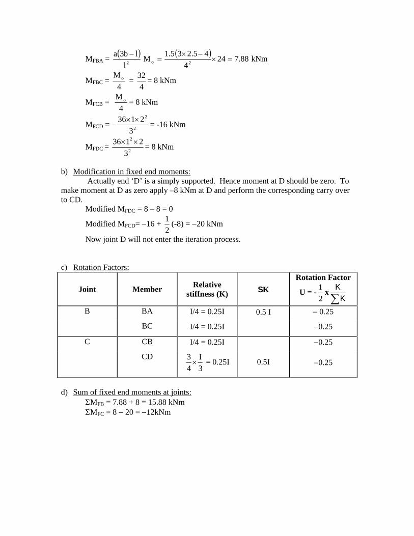
b) Modification in fixed end moments:Actually end ‘D’ is a simply supported. Hence moment at D should be zero. To
make moment at D as zero apply –8 kNm at D and perform the corresponding carry overto CD.
Modified MFDC = 8 – 8 = 0
Modified MFCD= 16 +2
1(-8) = 20 kNm
Now joint D will not enter the iteration process.
c) Rotation Factors:
Joint Member Relativestiffness (K) K
Rotation Factor
U = -2
1xKK
B BA I/4 = 0.25I 0.5 I 0.25
BC I/4 = 0.25I 0.25
C CB I/4 = 0.25I
0.5I
0.25
CD
3
I
4
3 = 0.25I 0.25
d) Sum of fixed end moments at joints:MFB = 7.88 + 8 = 15.88 kNmMFC = 8 20 = 12kNm
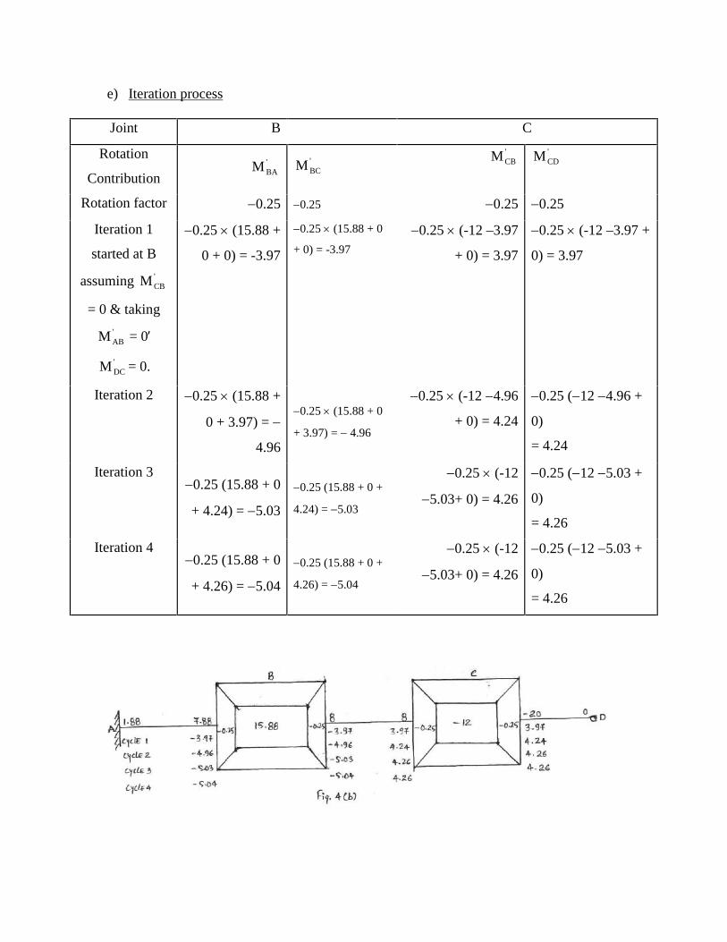
e) Iteration process
Joint B C
Rotation
Contribution'BAM '
BCM'CBM '
CDM
Rotation factor 0.25 0.25 0.25 0.25
Iteration 1
started at B
assuming 'CBM
= 0 & taking
'ABM = 0
'DCM = 0.
0.25 (15.88 +
0 + 0) = -3.97
0.25 (15.88 + 0
+ 0) = -3.97
0.25 (-12 –3.97
+ 0) = 3.97
0.25 (-12 –3.97 +
0) = 3.97
Iteration 2 0.25 (15.88 +
0 + 3.97) =
4.96
0.25 (15.88 + 0
+ 3.97) = 4.96
0.25 (-12 4.96
+ 0) = 4.24
0.25 (12 4.96 +
0)
= 4.24
Iteration 30.25 (15.88 + 0
+ 4.24) = 5.03
0.25 (15.88 + 0 +
4.24) = 5.03
0.25 (-12
5.03+ 0) = 4.26
0.25 (12 5.03 +
0)
= 4.26
Iteration 40.25 (15.88 + 0
+ 4.26) = 5.04
0.25 (15.88 + 0 +
4.26) = 5.04
0.25 (-12
5.03+ 0) = 4.26
0.25 (12 5.03 +
0)
= 4.26
Iteration process has been stopped after 4th cycle since rotation contribution values arebecoming almost constant. Values of fixed end moments, sum of fixed end moments,rotation factors along with rotation contribution values after end of each cycle inappropriate places has been shown in fig. 4 (b).
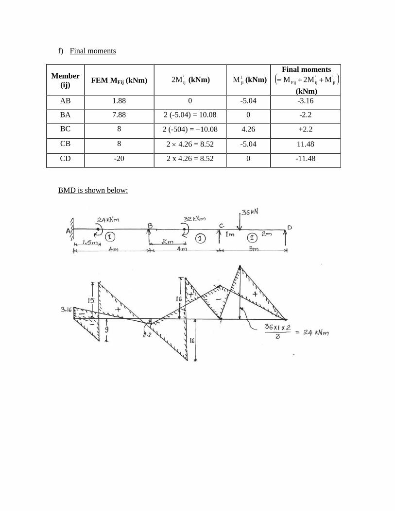
f) Final moments
Member(ij)
FEM MFij (kNm) 'ijM2 (kNm) 1
jiM (kNm)Final moments '
ji'ijFij MM2M
(kNm)AB 1.88 0 -5.04 -3.16
BA 7.88 2 (-5.04) = 10.08 0 -2.2
BC 8 2 (-504) = 10.08 4.26 +2.2
CB 8 2 4.26 = 8.52 -5.04 11.48
CD -20 2 x 4.26 = 8.52 0 -11.48
BMD is shown below:
VTU – EDUSAT Programme – 7Class: B.E. V Sem (Civil Engineering) Sub: Structural Analysis – II (CV51)
Session on 12.10.2007KANI’S METHOD FOR ANALYSIS OF INDETERMINATE
STRUCTURES (CONTD.)By A.B.Harwalkar
P.D.A.College of Engg Gulbarga
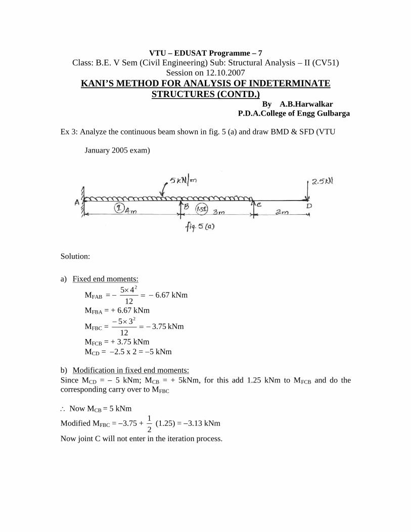
Ex 3: Analyze the continuous beam shown in fig. 5 (a) and draw BMD & SFD (VTU
January 2005 exam)
Solution:
a) Fixed end moments:
MFAB = 12
45 2
6.67 kNm
MFBA = + 6.67 kNm
MFBC = 75.312
35 2
kNm
MFCB = + 3.75 kNmMCD = 2.5 x 2 = 5 kNm
b) Modification in fixed end moments:Since MCD = 5 kNm; MCB = + 5kNm, for this add 1.25 kNm to MFCB and do thecorresponding carry over to MFBC
Now MCB = 5 kNm
Modified MFBC = 3.75 +2
1(1.25) = 3.13 kNm
Now joint C will not enter in the iteration process.
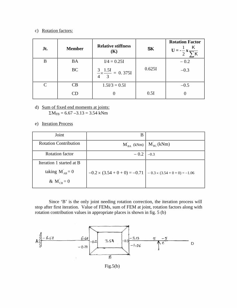
c) Rotation factors:
Jt. Member Relative stiffness(K) K
Rotation Factor
U = -2
1xKK
B BA I/4 = 0.25I
0.625I
0.2
BC
3
I5.1
4
3 = 0. 375I
0.3
C CB 1.5I/3 = 0.5I
0.5I
0.5
CD 0 0
d) Sum of fixed end moments at joints:MFB = 6.67 –3.13 = 3.54 kNm
e) Iteration Process
Joint B
Rotation Contribution 'BAM (kNm)
'BCM (kNm)
Rotation factor 0.2 0.3
Iteration 1 started at B
taking 'ABM = 0
& 'CBM = 0
0.2 (3.54 + 0 + 0) = 0.71 0.3 (3.54 + 0 + 0) = 1.06
Since ‘B’ is the only joint needing rotation correction, the iteration process willstop after first iteration. Value of FEMs, sum of FEM at joint, rotation factors along withrotation contribution values in appropriate places is shown in fig. 5 (b)
Fig.5(b)
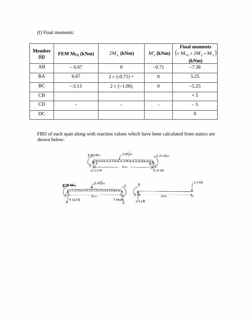
(f) Final moments:
Member(ij)
FEM MFij (kNm) 'ijM2 (kNm) 1
jiM (kNm)Final moments '
ji'ijFij MM2M
(kNm)AB 6.67 0 0.71 7.38
BA 6.67 2 (-0.71) = 0 5.25
BC 3.13 2 (1.06) 0 5.25
CB + 5
CD - - - 5
DC 0
FBD of each span along with reaction values which have been calculated from statics areshown below:
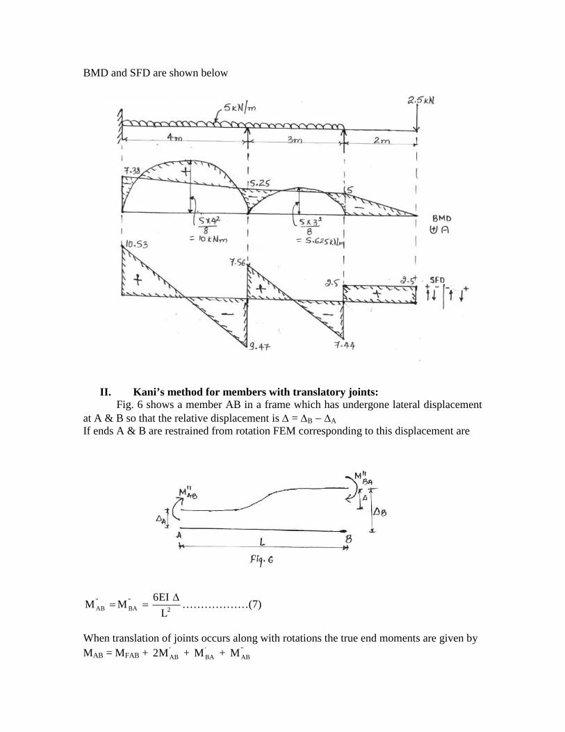
BMD and SFD are shown below
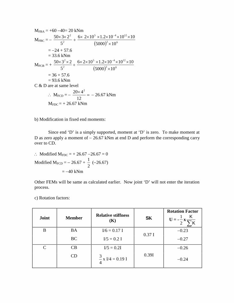
II. Kani’s method for members with translatory joints:Fig. 6 shows a member AB in a frame which has undergone lateral displacement
at A & B so that the relative displacement is = B A
If ends A & B are restrained from rotation FEM corresponding to this displacement are
2''BA
''AB L
EI6MM
………………(7)
When translation of joints occurs along with rotations the true end moments are given byMAB = MFAB + '
ABM2 + 'BAM + ''
ABM
MBA = MFBA + 'BAM2 + '
ABM + ''BAM
If ‘A’ happens to be a joint where two or more members meet then fromequilibrium of joint we have
MAB = 0MFAB + 2 '
ABM + 'BAM + ''
ABM = 0
'ABM =
2
1 ''AB
'BAFAB MMM ……………(8)
we know from equation (5)
'ABM = '
ABAB
AB MK
K
Using equation (8) 'ABM =
2
1 ''AB
'BAFAB
AB
AB MMMK
K
= ''AB
'BAFAAB MMMU
Similarly 'BAM = UBA ''
BA'ABFB MMM ……………..(9)
Using the above relationships rotation contributions can be determined byiterative procedure. If lateral displacements are known the displacement moments can bedetermined from equation (7). If lateral displacements are unknown then additionalequations have to be developed for analyzing the member.
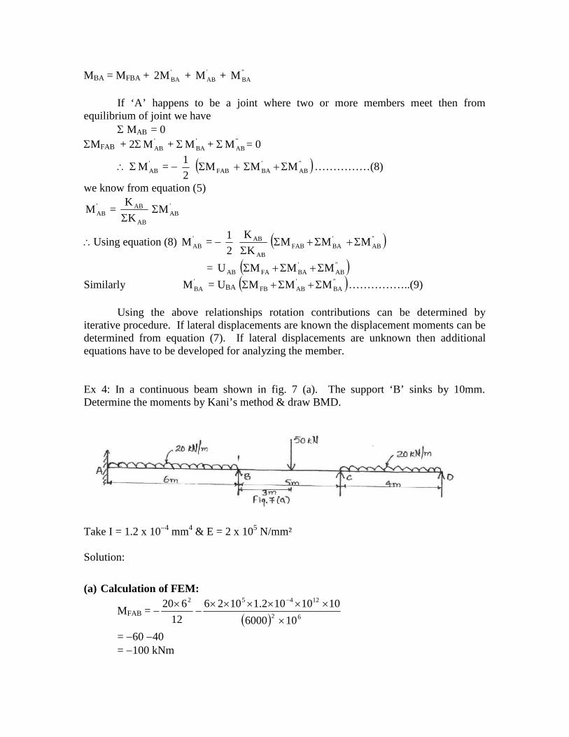
Ex 4: In a continuous beam shown in fig. 7 (a). The support ‘B’ sinks by 10mm.Determine the moments by Kani’s method & draw BMD.
Take I = 1.2 x 104 mm4 & E = 2 x 10⁵ N/mm²
Solution:
(a) Calculation of FEM:
MFAB = 62
12452
106000
1010102.11026
12
620
= 60 40= 100 kNm
MFBA = +60 40= 20 kNm
MFBC = 62
1245
2
2
105000
1010102.11026
5
2350
= 24 + 57.6= 33.6 kNm
MFCB = + 62
1245
2
2
105000
1010102.11026
5
2350
= 36 + 57.6= 93.6 kNm
C & D are at same level
MFCD =
12
420 2
26.67 kNm
MFDC = + 26.67 kNm
b) Modification in fixed end moments:
Since end ‘D’ is a simply supported, moment at ‘D’ is zero. To make moment atD as zero apply a moment of 26.67 kNm at end D and perform the corresponding carryover to CD.
Modified MFDC = + 26.67 26.67 = 0
Modified MFCD = 26.67 +2
1(26.67)
= 40 kNm
Other FEMs will be same as calculated earlier. Now joint ‘D’ will not enter the iterationprocess.
c) Rotation factors:
Joint MemberRelative stiffness
(K) K
Rotation Factor
U = -2
1xKK
B BA I/6 = 0.17 I0.37 I
0.23
BC I/5 = 0.2 I 0.27
C CB I/5 = 0.2I
0.39I
0.26
CD
4
3x I/4 = 0.19 I 0.24
d) Sum of fixed end moments:
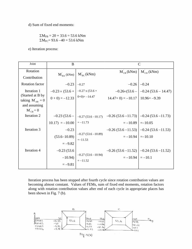
MFB = 20 + 33.6 = 53.6 kNmMFC= 93.6 40 = 53.6 kNm
e) Iteration process:
Joint B C
Rotation
Contribution'BAM (kNm)
'BCM (kNm)
'CBM (kNm) '
CDM (kNm)
Rotation factor 0.23 0.27 0.26 0.24
Iteration 1(Started at B bytaking '
ABM = 0and assuming
M 'CB = 0
0.23 (53.6 +
0 + 0) = 12.33
0.27 x (53.6 +
0+0)= 14.47
0.26(53.6 –
14.47+ 0) = 10.17
0.24 (53.6 14.47)
10.96= 9.39
Iteration 2 0.23 (53.6
10.17) = 10.00
0.27 (53.6 10.17)
= 11.73
0.26 (53.6 11.73)
= 10.89
0.24 (53.6 11.73)
=10.05
Iteration 3 0.23
(53.610.89)
= 9.82
0.27 (53.6 10.89)
=11.53
0.26 (53.6 11.53)
= 10.94
0.24 (53.6 11.53)
=10.10
Iteration 4 0.23 (53.6
10.94)
= 9.81
0.27 (53.6 10.94)
= 11.52
0.26 (53.6 11.52)
= 10.94
0.24 (53.6 11.52)
= 10.1
Iteration process has been stopped after fourth cycle since rotation contribution values arebecoming almost constant. Values of FEMs, sum of fixed end moments, rotation factorsalong with rotation contribution values after end of each cycle in appropriate places hasbeen shown in Fig. 7 (b).

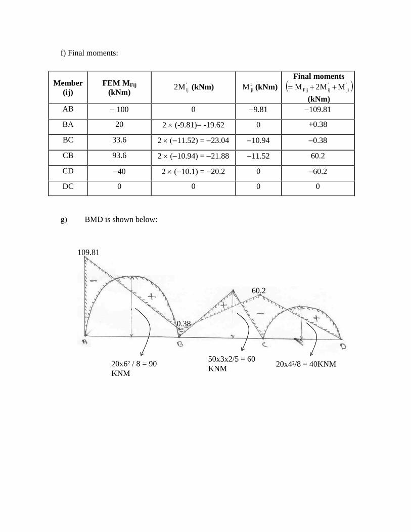
f) Final moments:
Member(ij)
FEM MFij
(kNm)'ijM2 (kNm) 1
jiM (kNm)Final moments '
ji'ijFij MM2M
(kNm)AB 100 0 9.81 109.81
BA 20 2 (-9.81)= -19.62 0 +0.38
BC 33.6 2 11.52) = 23.04 10.94 0.38
CB 93.6 2 (10.94) = 21.88 11.52 60.2
CD 40 2 (10.1) = 20.2 0 60.2
DC 0 0 0 0
g) BMD is shown below:
109.81
20x6² / 8 = 90KNM
0.38
60.2
50x3x2/5 = 60KNM 20x4²/8 = 40KNM
VTU – EDUSAT Programme – 7Class: B.E. V SEM (Civil Engineering) SUB: Structural Analysis – II (CV51)
Session on 15.10.2007KANI’S METHOD FOR ANALYSIS OF INDETERMINATE STRUCTURES
(CONTD.)BY A.B.HARWALKAR
P.D.A.College of Engg Gulbarga
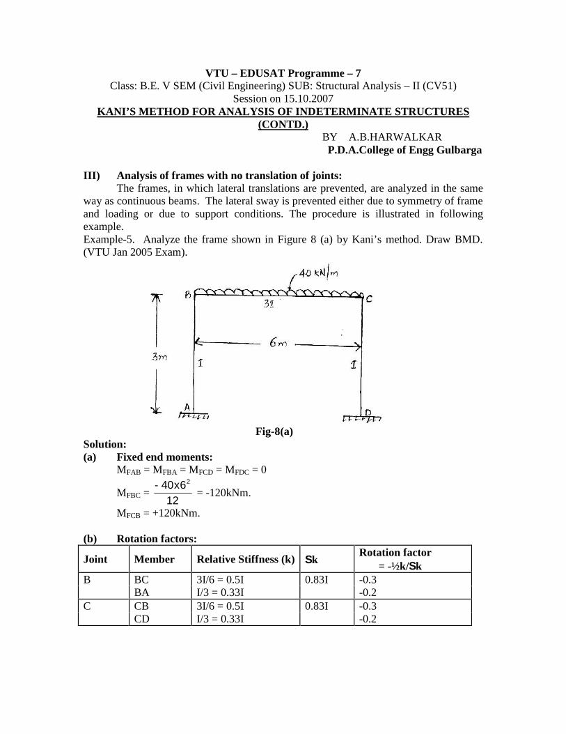
III) Analysis of frames with no translation of joints:The frames, in which lateral translations are prevented, are analyzed in the same
way as continuous beams. The lateral sway is prevented either due to symmetry of frameand loading or due to support conditions. The procedure is illustrated in followingexample.Example-5. Analyze the frame shown in Figure 8 (a) by Kani’s method. Draw BMD.(VTU Jan 2005 Exam).
Fig-8(a)Solution:(a) Fixed end moments:
MFAB = MFBA = MFCD = MFDC = 0
MFBC =12
6x40- 2
= -120kNm.
MFCB = +120kNm.
(b) Rotation factors:
Joint Member Relative Stiffness (k) kRotation factor
= -½k/kB BC 3I/6 = 0.5I 0.83I -0.3
BA I/3 = 0.33I -0.2C CB 3I/6 = 0.5I 0.83I -0.3
CD I/3 = 0.33I -0.2
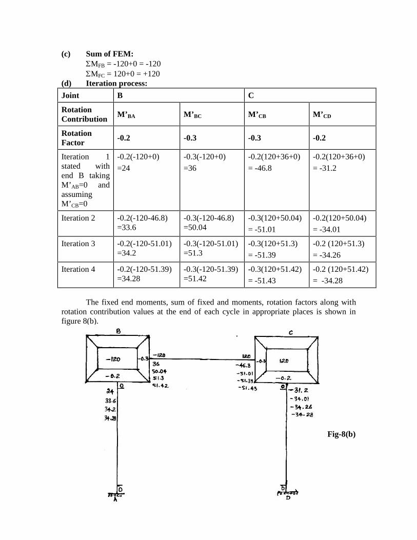
(c) Sum of FEM:MFB = -120+0 = -120MFC = 120+0 = +120
(d) Iteration process:
Joint B C
RotationContribution
M’BA M’BC M’CB M’CD
RotationFactor
-0.2 -0.3 -0.3 -0.2
Iteration 1stated withend B takingM’AB=0 andassumingM’CB=0
-0.2(-120+0)
=24
-0.3(-120+0)
=36
-0.2(120+36+0)
= -46.8
-0.2(120+36+0)
= -31.2
Iteration 2 -0.2(-120-46.8)=33.6
-0.3(-120-46.8)=50.04
-0.3(120+50.04)
= -51.01
-0.2(120+50.04)
= -34.01
Iteration 3 -0.2(-120-51.01)=34.2
-0.3(-120-51.01)=51.3
-0.3(120+51.3)
= -51.39
-0.2 (120+51.3)
= -34.26
Iteration 4 -0.2(-120-51.39)=34.28
-0.3(-120-51.39)=51.42
-0.3(120+51.42)
= -51.43
-0.2 (120+51.42)
= -34.28
The fixed end moments, sum of fixed and moments, rotation factors along withrotation contribution values at the end of each cycle in appropriate places is shown infigure 8(b).
Fig-8(b)
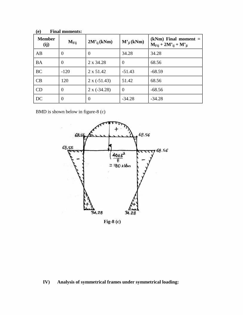
(e) Final moments:
Member(ij)
MFij 2M’ij (kNm) M’ji (kNm)(kNm) Final moment =MFij + 2M’ij + M’ji
AB 0 0 34.28 34.28
BA 0 2 x 34.28 0 68.56
BC -120 2 x 51.42 -51.43 -68.59
CB 120 2 x (-51.43) 51.42 68.56
CD 0 2 x (-34.28) 0 -68.56
DC 0 0 -34.28 -34.28
BMD is shown below in figure-8 (c)
Fig-8 (c)
IV) Analysis of symmetrical frames under symmetrical loading:
Considerable calculation work can be saved if we make use of symmetry offrames and loading especially when analysis is done manually. Two cases of symmetryarise, namely, frames in which the axis of symmetry passes through the centerline of thebeams and frames with the axis of symmetry passing through column line.
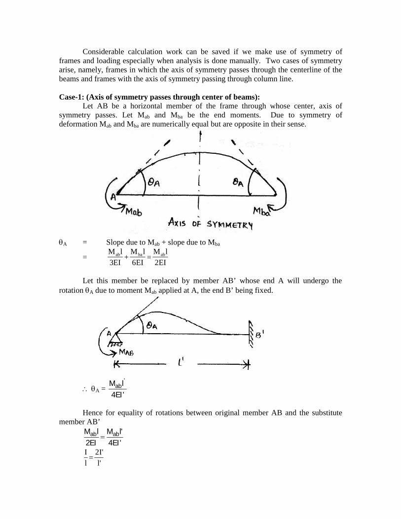
Case-1: (Axis of symmetry passes through center of beams):Let AB be a horizontal member of the frame through whose center, axis of
symmetry passes. Let Mab and Mba be the end moments. Due to symmetry ofdeformation Mab and Mba are numerically equal but are opposite in their sense.
A = Slope due to Mab + slope due to Mba
=EI2
lM=
EI6
lM+
EI3
lM abbaab
Let this member be replaced by member AB’ whose end A will undergo therotation A due to moment Mab applied at A, the end B’ being fixed.
A ='EI4lM '
ab
Hence for equality of rotations between original member AB and the substitutemember AB’
'EI4'lM
EI2lM abab
'l
'I2=
l
I
K = 2K’
K’ =2K
Thus if K is the relative stiffness of original member AB, this member can be
replaced by substitute member AB’ having relative stiffness2
K. With this substitute
member, the analysis need to be carried out for only, one half of the frame consideringline of symmetry as fixed.
VTU – EDUSAT Programme – 7Class: B.E. V SEM (Civil Engineering) SUB: Structural Analysis – II (CV51)
Session on 16.10.2007KANI’S METHOD FOR ANALYSIS OF INDETERMINATE
STRUCTURES (CONTD.)BY A.B.HARWALKARP.D.A.College of Engg Gulbarga
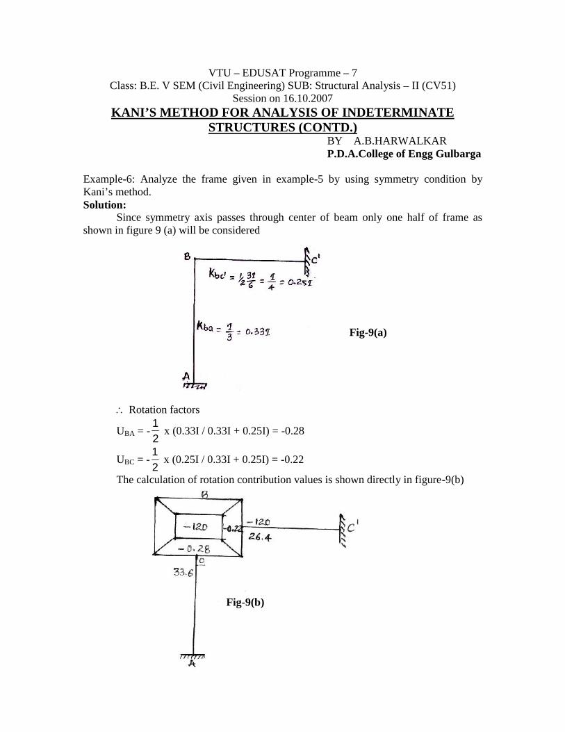
Example-6: Analyze the frame given in example-5 by using symmetry condition byKani’s method.Solution:
Since symmetry axis passes through center of beam only one half of frame asshown in figure 9 (a) will be considered
Fig-9(a)
Rotation factors
UBA = -21
x (0.33I / 0.33I + 0.25I) = -0.28
UBC = -21
x (0.25I / 0.33I + 0.25I) = -0.22
The calculation of rotation contribution values is shown directly in figure-9(b)
Fig-9(b)
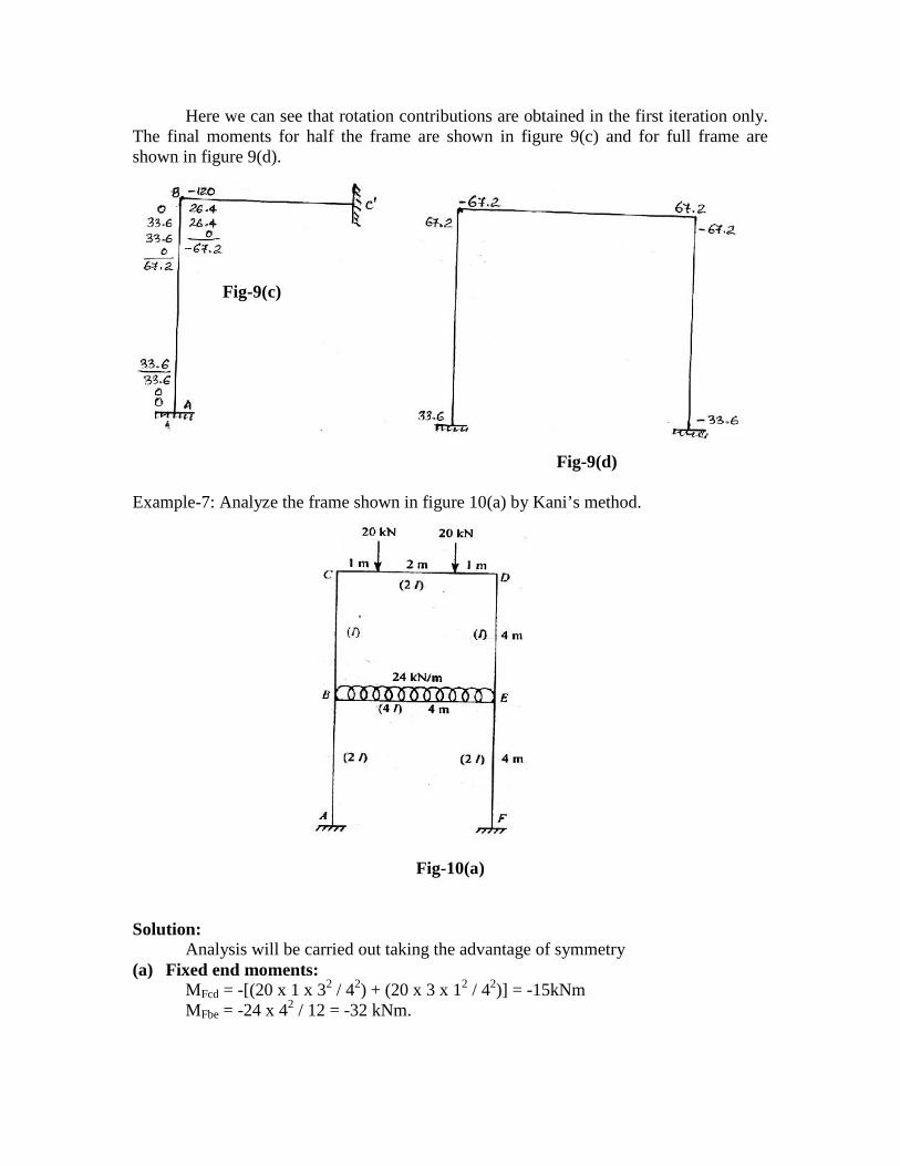
Here we can see that rotation contributions are obtained in the first iteration only.The final moments for half the frame are shown in figure 9(c) and for full frame areshown in figure 9(d).
Fig-9(d)
Example-7: Analyze the frame shown in figure 10(a) by Kani’s method.
Fig-10(a)
Solution:Analysis will be carried out taking the advantage of symmetry
(a) Fixed end moments:MFcd = -[(20 x 1 x 32 / 42) + (20 x 3 x 12 / 42)] = -15kNmMFbe = -24 x 42 / 12 = -32 kNm.
Fig-9(c)
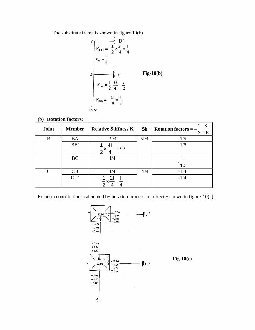
The substitute frame is shown in figure 10(b)
Fig-10(b)
(b) Rotation factors:
Joint Member Relative Stiffness K k Rotation factors = –KΣ
K21
B BA 2I/4 5I/4 -1/5BE’
2/I=4I4
x21 -1/5
BC I/4-101
C CB I/4 2I/4 -1/4CD’
4I
=4I2
x21 -1/4
Rotation contributions calculated by iteration process are directly shown in figure-10(c).
'
Fig-10(c)'
D’KCD’ = 4
I=
4I2
x21
Kba =2I
=4I2
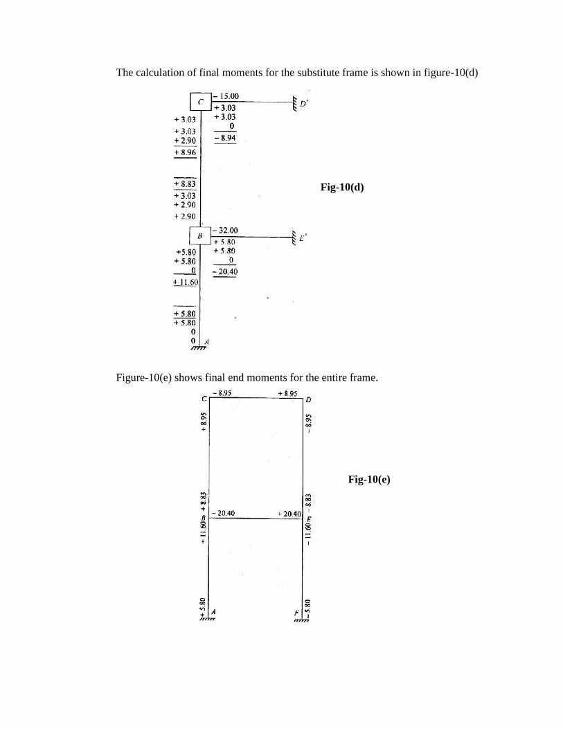
The calculation of final moments for the substitute frame is shown in figure-10(d)
Fig-10(d)
Figure-10(e) shows final end moments for the entire frame.
Fig-10(e)
VTU – EDUSAT Programme – 7Class: B.E. V SEM (Civil Engineering) SUB: Structural Analysis – II (CV51)
Session on 19.10.2007KANI’S METHOD FOR ANALYSIS OF INDETERMINATE
STRUCTURES (CONTD.)BY A.B.HARWALKAR
P.D.A.College of Engg Gulbarga
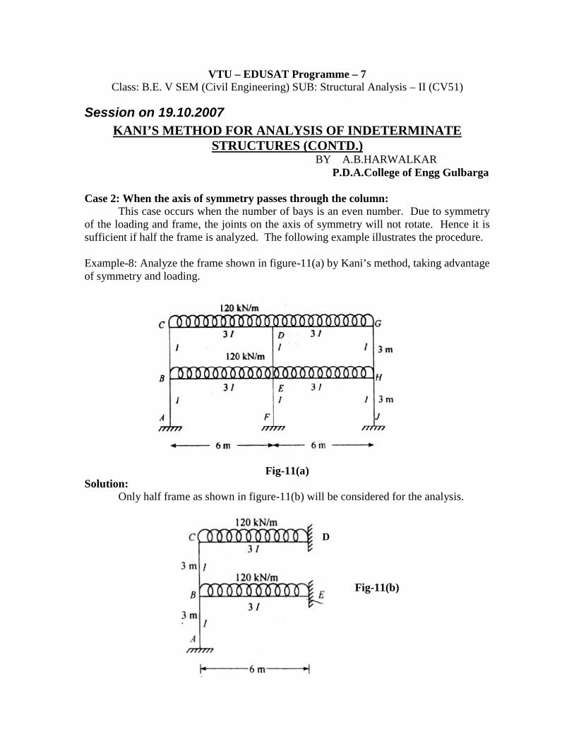
Case 2: When the axis of symmetry passes through the column:This case occurs when the number of bays is an even number. Due to symmetry
of the loading and frame, the joints on the axis of symmetry will not rotate. Hence it issufficient if half the frame is analyzed. The following example illustrates the procedure.
Example-8: Analyze the frame shown in figure-11(a) by Kani’s method, taking advantageof symmetry and loading.
Fig-11(a)Solution:
Only half frame as shown in figure-11(b) will be considered for the analysis.
Fig-11(b)
D
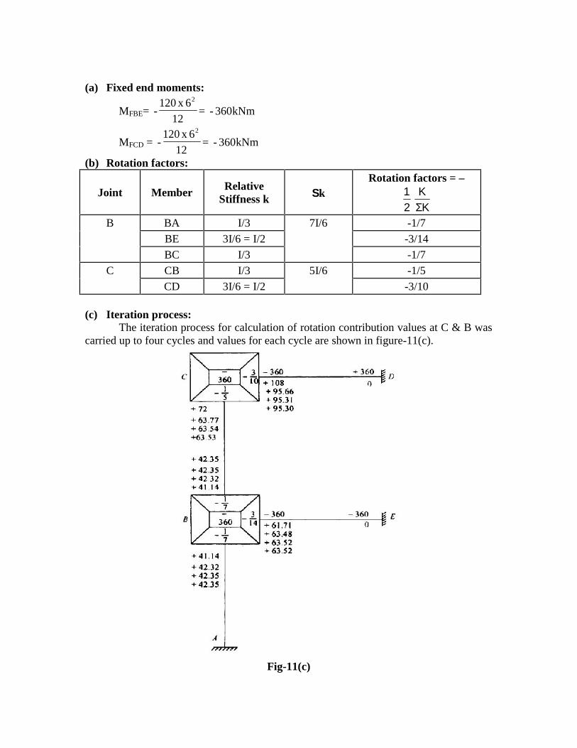
(a) Fixed end moments:
MFBE= kNm360-=12
6x120-
2
MFCD = kNm360-=12
6x120-
2
(b) Rotation factors:
Joint Member RelativeStiffness k k
Rotation factors = –
KΣK
21
B BA I/3 7I/6 -1/7
BE 3I/6 = I/2 -3/14
BC I/3 -1/7
C CB I/3 5I/6 -1/5
CD 3I/6 = I/2 -3/10
(c) Iteration process:The iteration process for calculation of rotation contribution values at C & B was
carried up to four cycles and values for each cycle are shown in figure-11(c).
Fig-11(c)
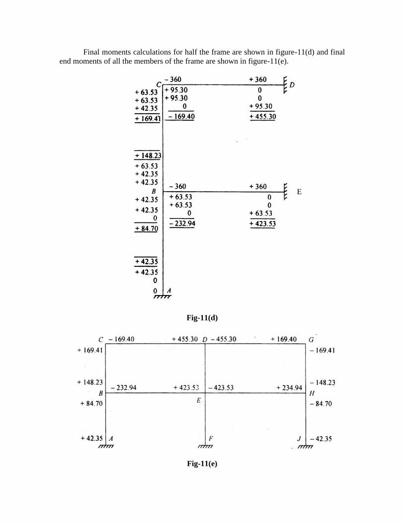
Final moments calculations for half the frame are shown in figure-11(d) and finalend moments of all the members of the frame are shown in figure-11(e).
Fig-4(d)
Fig-11(d)
Fig-11(e)
E
Recommended