8/14/2019 Chapter 02-1.ppt
http://slidepdf.com/reader/full/chapter-02-1ppt 1/101
Chapter 2
Resistive Circuits
Chapter 2
Resistive Circuits
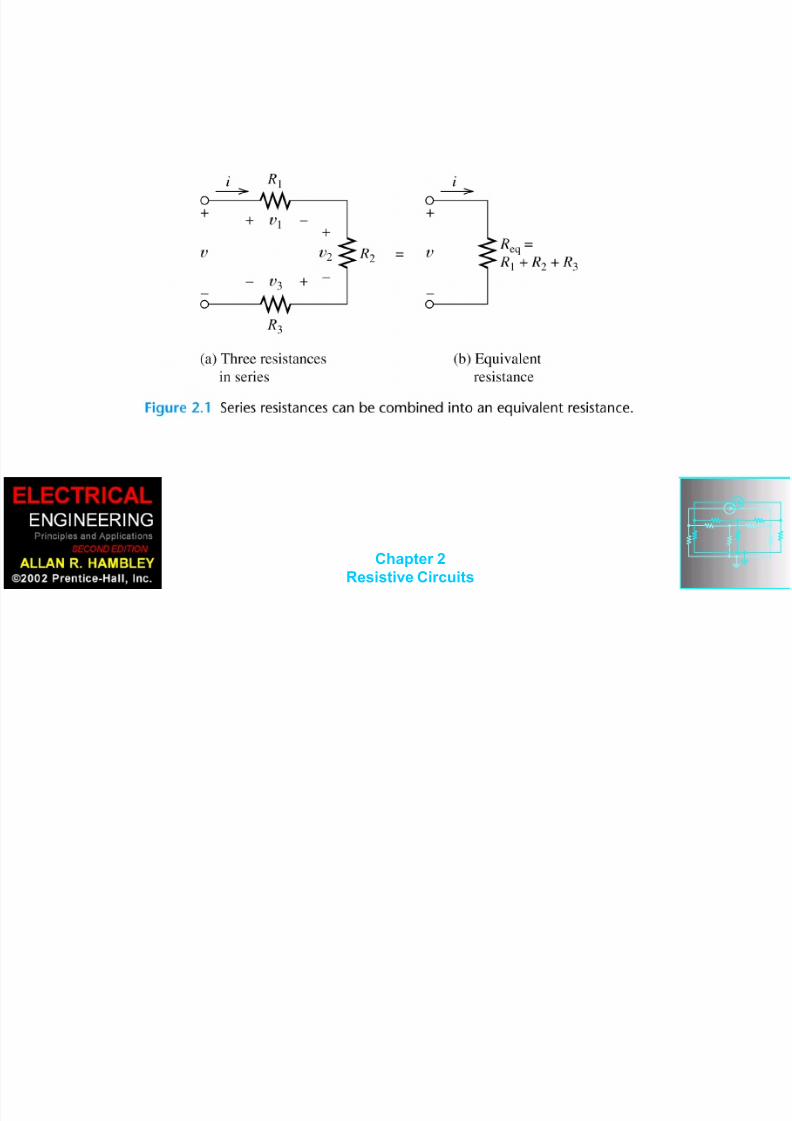
1. Solve circuits (i.e., find currents and
voltages of interest) by combining
resistances in series and parallel.
2. Apply the voltage-division and current-
division
principles.3. Solve circuits by the node-voltage
technique.
8/14/2019 Chapter 02-1.ppt
http://slidepdf.com/reader/full/chapter-02-1ppt 2/101
Chapter 2
Resistive Circuits
4. Solve circuits by the mesh-current technique.
5. Find Thévenin and Norton equivalents.
6. Apply the superposition principle.
7. Draw the circuit diagram and state the principl
of operation for the Wheatstone bridge.
8/14/2019 Chapter 02-1.ppt
http://slidepdf.com/reader/full/chapter-02-1ppt 3/101
Chapter 2
Resistive Circuits

8/14/2019 Chapter 02-1.ppt
http://slidepdf.com/reader/full/chapter-02-1ppt 4/101
Chapter 2
Resistive Circuits

8/14/2019 Chapter 02-1.ppt
http://slidepdf.com/reader/full/chapter-02-1ppt 5/101
Chapter 2
Resistive Circuits
8/14/2019 Chapter 02-1.ppt
http://slidepdf.com/reader/full/chapter-02-1ppt 6/101
Chapter 2
Resistive Circuits

8/14/2019 Chapter 02-1.ppt
http://slidepdf.com/reader/full/chapter-02-1ppt 7/101
Chapter 2
Resistive Circuits
Circuit Analysis using
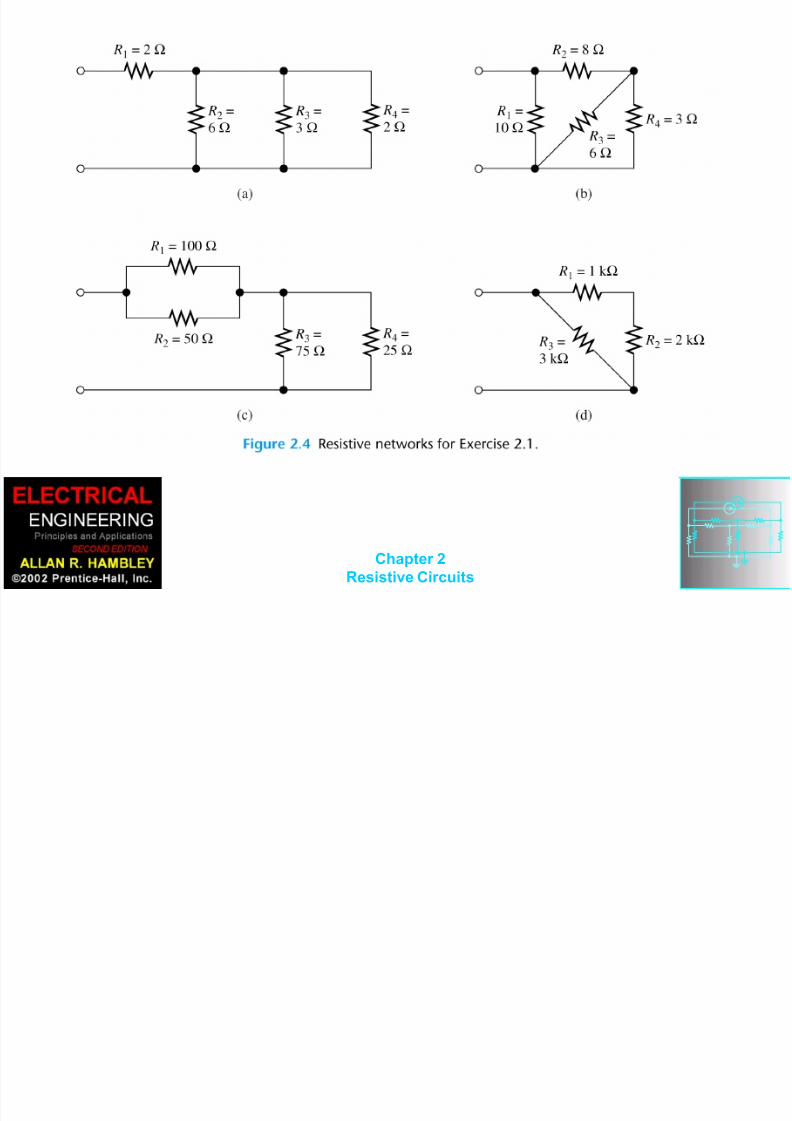
Series/Parallel Equivalents1. Begin by locating a combination of
resistances that are in series or parallel.
Often the place to start is farthest from thesource.
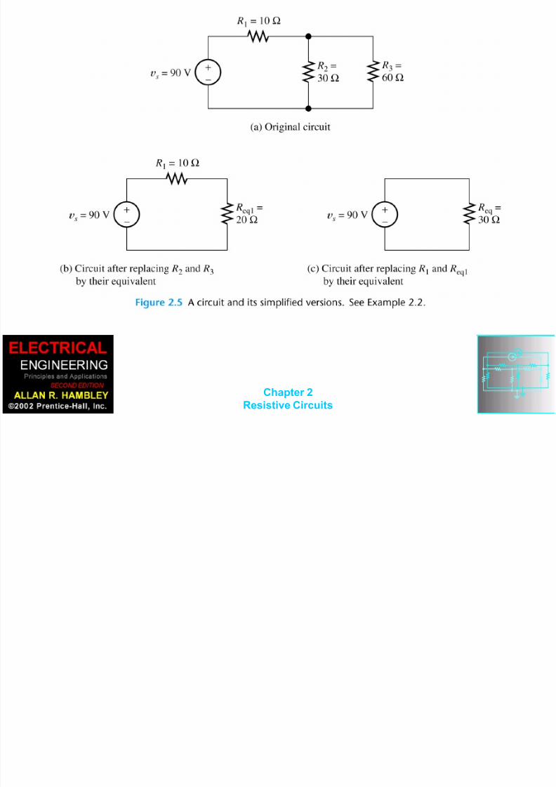
2. Redraw the circuit with the equivalentresistance for the combination found instep 1.

8/14/2019 Chapter 02-1.ppt
http://slidepdf.com/reader/full/chapter-02-1ppt 8/101
Chapter 2Resistive Circuits
3. Repeat steps 1 and 2 until the circuit isreduced as far as possible. Often (but notalways) we end up with a single source anda single resistance.
4. Solve for the currents and voltages in thefinal equivalent circuit.
8/14/2019 Chapter 02-1.ppt
http://slidepdf.com/reader/full/chapter-02-1ppt 9/101
Chapter 2Resistive Circuits

8/14/2019 Chapter 02-1.ppt
http://slidepdf.com/reader/full/chapter-02-1ppt 10/101
Chapter 2Resistive Circuits

8/14/2019 Chapter 02-1.ppt
http://slidepdf.com/reader/full/chapter-02-1ppt 11/101
Chapter 2Resistive Circuits

8/14/2019 Chapter 02-1.ppt
http://slidepdf.com/reader/full/chapter-02-1ppt 12/101
Chapter 2Resistive Circuits

8/14/2019 Chapter 02-1.ppt
http://slidepdf.com/reader/full/chapter-02-1ppt 13/101
Chapter 2Resistive Circuits
Voltage Division
total
321
111 v
R R R
Ri Rv
total
321
222 v
R R R
Ri Rv

8/14/2019 Chapter 02-1.ppt
http://slidepdf.com/reader/full/chapter-02-1ppt 14/101
Chapter 2Resistive Circuits

8/14/2019 Chapter 02-1.ppt
http://slidepdf.com/reader/full/chapter-02-1ppt 15/101
Chapter 2Resistive Circuits
Application of the Voltage-
Division Principle
V5.1
156000200010001000
1000
total
4321
11
v
R R R R
Rv

8/14/2019 Chapter 02-1.ppt
http://slidepdf.com/reader/full/chapter-02-1ppt 16/101
Chapter 2Resistive Circuits
8/14/2019 Chapter 02-1.ppt
http://slidepdf.com/reader/full/chapter-02-1ppt 17/101
Chapter 2Resistive Circuits
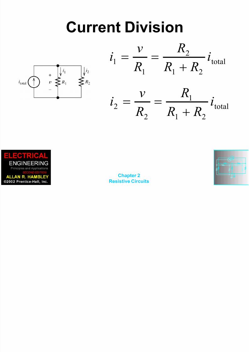
Current Division
total
21
2
1
1 i R R
R
R
vi
total
21
1
2
2 i R R
R
R
vi
8/14/2019 Chapter 02-1.ppt
http://slidepdf.com/reader/full/chapter-02-1ppt 18/101
Chapter 2Resistive Circuits

8/14/2019 Chapter 02-1.ppt
http://slidepdf.com/reader/full/chapter-02-1ppt 19/101
Chapter 2Resistive Circuits
8/14/2019 Chapter 02-1.ppt
http://slidepdf.com/reader/full/chapter-02-1ppt 20/101
Chapter 2Resistive Circuits
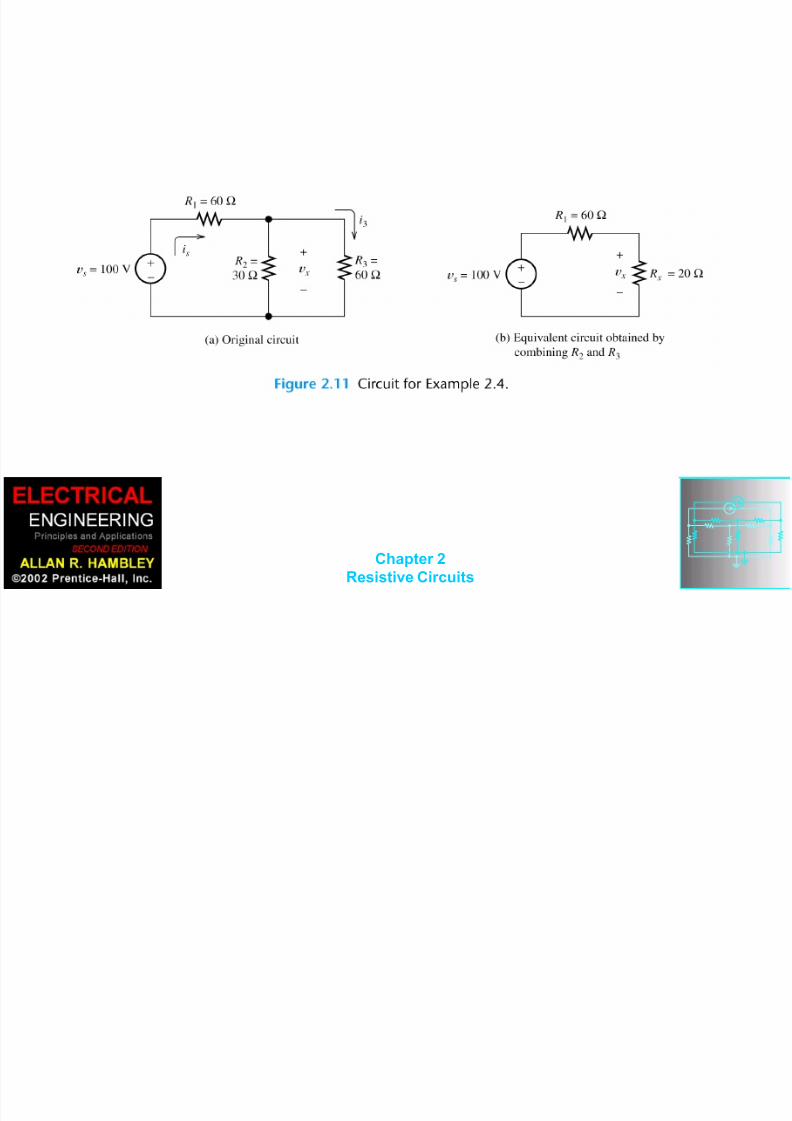
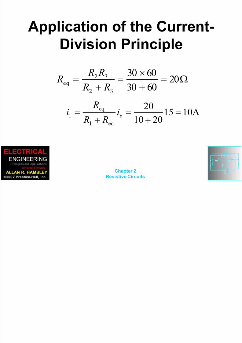
Application of the Current-
Division Principle
206030
6030
32
32
eq R R
R R R
A10152010
20
eq1
eq
1
si
R R
Ri

8/14/2019 Chapter 02-1.ppt
http://slidepdf.com/reader/full/chapter-02-1ppt 21/101
Chapter 2Resistive Circuits

8/14/2019 Chapter 02-1.ppt
http://slidepdf.com/reader/full/chapter-02-1ppt 22/101
Chapter 2Resistive Circuits
8/14/2019 Chapter 02-1.ppt
http://slidepdf.com/reader/full/chapter-02-1ppt 23/101
Chapter 2Resistive Circuits
Although they are very
important concepts,series/parallel equivalents and
the current/voltage divisionprinciples are not sufficient to
solve all circuits.

8/14/2019 Chapter 02-1.ppt
http://slidepdf.com/reader/full/chapter-02-1ppt 24/101
Chapter 2Resistive Circuits
Node Voltage Analysis

8/14/2019 Chapter 02-1.ppt
http://slidepdf.com/reader/full/chapter-02-1ppt 25/101
Chapter 2Resistive Circuits

8/14/2019 Chapter 02-1.ppt
http://slidepdf.com/reader/full/chapter-02-1ppt 26/101
Chapter 2Resistive Circuits
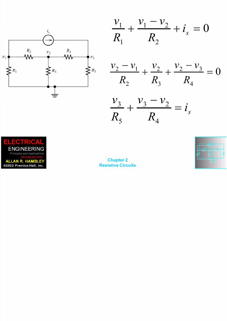
Writing KCL Equations in
Terms of the Node Voltagesfor Figure 2.16
s
vv 1
03
32
4
2
2
12
R
vv
R
v
R
vv
03
23
5
3
1
13
R
vv
R
v
R
vv

8/14/2019 Chapter 02-1.ppt
http://slidepdf.com/reader/full/chapter-02-1ppt 27/101
Chapter 2Resistive Circuits
8/14/2019 Chapter 02-1.ppt
http://slidepdf.com/reader/full/chapter-02-1ppt 28/101
Chapter 2Resistive Circuits
0
2
21
1
1
si
R
vv
R
v
04
32
3
2
2
12
R
vv
R
v
R
vv
si
R
vv
R
v
4
23
5
3

8/14/2019 Chapter 02-1.ppt
http://slidepdf.com/reader/full/chapter-02-1ppt 29/101
Chapter 2Resistive Circuits

8/14/2019 Chapter 02-1.ppt
http://slidepdf.com/reader/full/chapter-02-1ppt 30/101
Chapter 2Resistive Circuits

8/14/2019 Chapter 02-1.ppt
http://slidepdf.com/reader/full/chapter-02-1ppt 31/101
Chapter 2Resistive Circuits
8/14/2019 Chapter 02-1.ppt
http://slidepdf.com/reader/full/chapter-02-1ppt 32/101
Chapter 2Resistive Circuits

8/14/2019 Chapter 02-1.ppt
http://slidepdf.com/reader/full/chapter-02-1ppt 33/101
Chapter 2Resistive Circuits
8/14/2019 Chapter 02-1.ppt
http://slidepdf.com/reader/full/chapter-02-1ppt 34/101
Chapter 2Resistive Circuits
8/14/2019 Chapter 02-1.ppt
http://slidepdf.com/reader/full/chapter-02-1ppt 35/101
Chapter 2Resistive Circuits
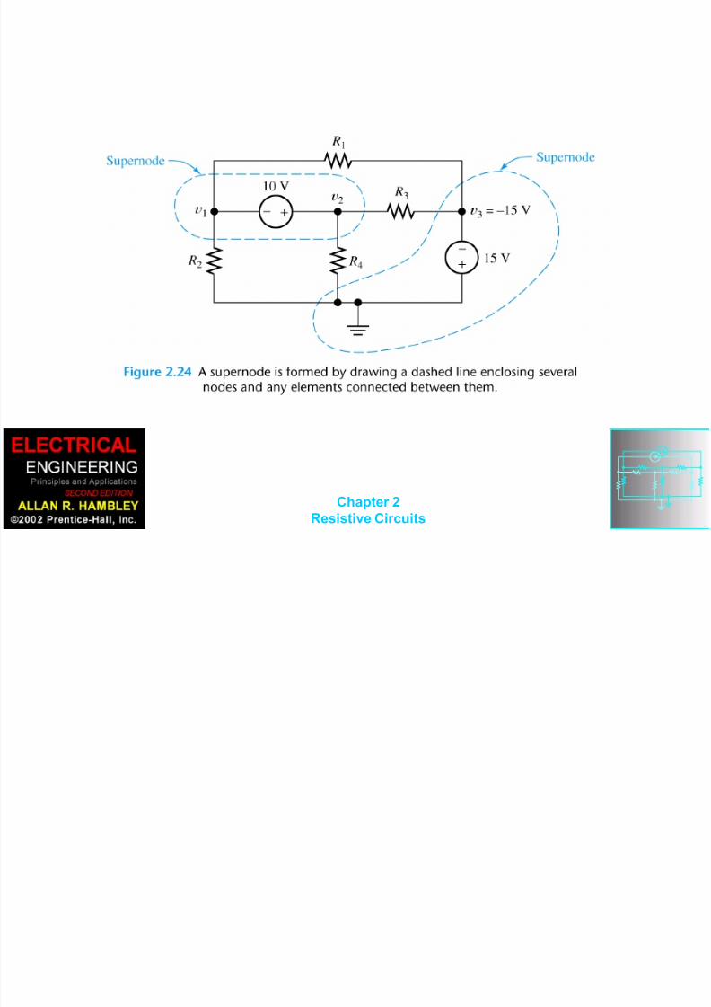
Circuits with Voltage
Sources
We obtain dependent
equations if we use all of thenodes in a network to write
KCL equations.

8/14/2019 Chapter 02-1.ppt
http://slidepdf.com/reader/full/chapter-02-1ppt 36/101
Chapter 2Resistive Circuits
0
1515
3
2
4
2
1
1
2
1
R
v
R
v
R
v
R
v

8/14/2019 Chapter 02-1.ppt
http://slidepdf.com/reader/full/chapter-02-1ppt 37/101
Chapter 2Resistive Circuits

8/14/2019 Chapter 02-1.ppt
http://slidepdf.com/reader/full/chapter-02-1ppt 38/101
Chapter 2Resistive Circuits
8/14/2019 Chapter 02-1.ppt
http://slidepdf.com/reader/full/chapter-02-1ppt 39/101
Chapter 2Resistive Circuits
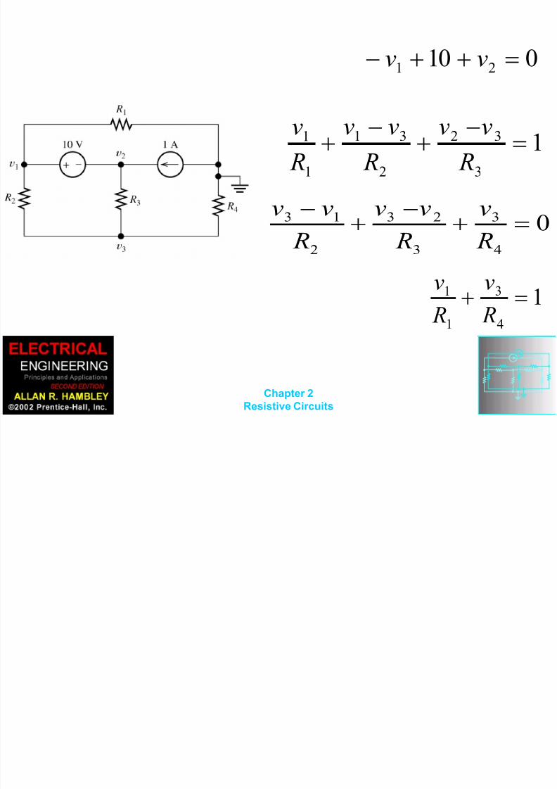
010 21 vv
13
32
2
31
1
1
R
vv
R
vv
R
v
0
4
3
3
23
2
13
R
v
R
vv
R
vv
14
3
1
1
R
v
R
v
8/14/2019 Chapter 02-1.ppt
http://slidepdf.com/reader/full/chapter-02-1ppt 40/101
Chapter 2Resistive Circuits
Node-Voltage Analysis with
a Dependent Source
First, we write KCL equationsat each node, including the
current of the controlled
source just as if it were anordinary current source.

8/14/2019 Chapter 02-1.ppt
http://slidepdf.com/reader/full/chapter-02-1ppt 41/101
Chapter 2Resistive Circuits

8/14/2019 Chapter 02-1.ppt
http://slidepdf.com/reader/full/chapter-02-1ppt 42/101
Chapter 2Resistive Circuits
x s ii
R
vv2
1
21
03
32
2
2
1
12
R
vv
R
v
R
vv
02
4
3
3
23
xi
R
v
R
vv
8/14/2019 Chapter 02-1.ppt
http://slidepdf.com/reader/full/chapter-02-1ppt 43/101
Chapter 2Resistive Circuits
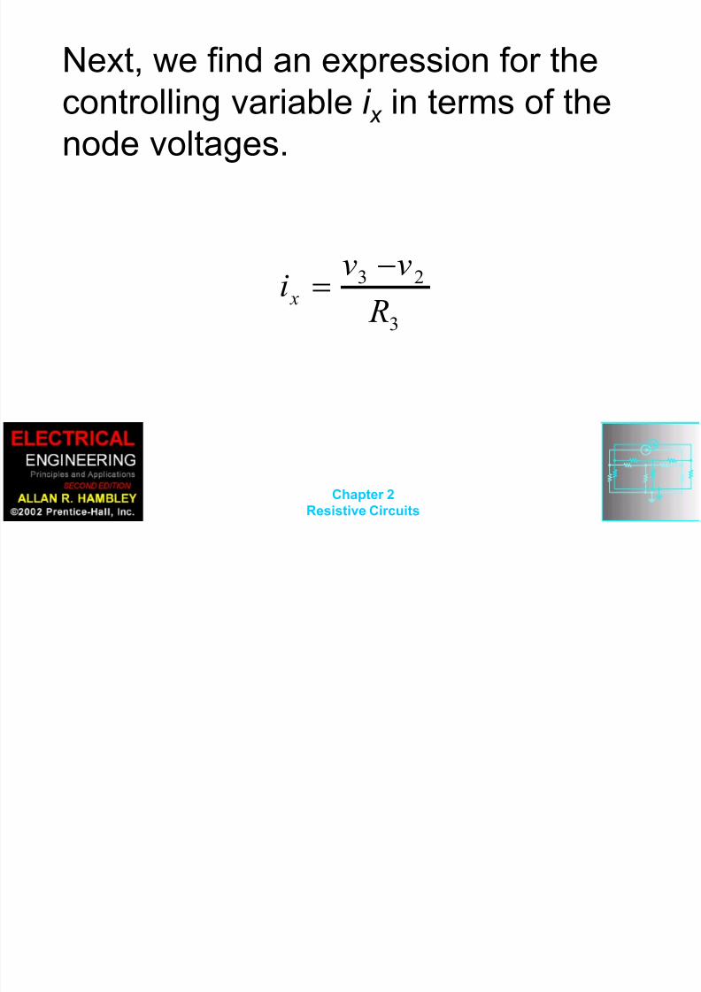
Next, we find an expression for the
controlling variable i x in terms of the
node voltages.
3
23
R
vvi x

8/14/2019 Chapter 02-1.ppt
http://slidepdf.com/reader/full/chapter-02-1ppt 44/101
Chapter 2Resistive Circuits
Substitution yields
3
23
1
21 2 R
vvi
R
vv s
03
32
2
2
1
12
R
vv
R
v
R
vv
023
23
4
3
3
23
R
vv
R
v
R
vv

8/14/2019 Chapter 02-1.ppt
http://slidepdf.com/reader/full/chapter-02-1ppt 45/101
Chapter 2Resistive Circuits

8/14/2019 Chapter 02-1.ppt
http://slidepdf.com/reader/full/chapter-02-1ppt 46/101
Chapter 2Resistive Circuits
Node-Voltage Analysis
1. Select a reference node and
assign variables for the unknown
node voltages. If the reference
node is chosen at one end of an
independent voltage source, one
node voltage is known at the
start, and fewer need to be
computed.

8/14/2019 Chapter 02-1.ppt
http://slidepdf.com/reader/full/chapter-02-1ppt 47/101
Chapter 2Resistive Circuits
2. Write network equations. First, use
KCL to write current equations for
nodesand supernodes. Write as many current
equations as you can without using all
ofthe nodes. Then if you do not have
enough equations because of voltage
sources
connected between nodes, use KVL to
write additional equations.
8/14/2019 Chapter 02-1.ppt
http://slidepdf.com/reader/full/chapter-02-1ppt 48/101
Chapter 2Resistive Circuits
3. If the circuit contains dependent
sources, find expressions for the
controlling variables in terms of the
node voltages. Substitute into the
network equations, and obtain
equations having only the node
voltages as unknowns.
8/14/2019 Chapter 02-1.ppt
http://slidepdf.com/reader/full/chapter-02-1ppt 49/101
Chapter 2Resistive Circuits
4. Put the equations into standard formand solve for the node voltages.
5. Use the values found for the nodevoltages to calculate any other
currents or voltages of interest.
8/14/2019 Chapter 02-1.ppt
http://slidepdf.com/reader/full/chapter-02-1ppt 50/101
Chapter 2Resistive Circuits

8/14/2019 Chapter 02-1.ppt
http://slidepdf.com/reader/full/chapter-02-1ppt 51/101
Chapter 2Resistive Circuits

8/14/2019 Chapter 02-1.ppt
http://slidepdf.com/reader/full/chapter-02-1ppt 52/101
Chapter 2Resistive Circuits
Mesh Current Analysis
8/14/2019 Chapter 02-1.ppt
http://slidepdf.com/reader/full/chapter-02-1ppt 53/101
Chapter 2Resistive Circuits
Choosing the Mesh
Currents When several mesh currents flow throughone element, we consider the current in
that element to be the algebraic sum of
the mesh currents.
Sometimes it is said that the mesh
currents are defined by “soaping thewindow panes.”

8/14/2019 Chapter 02-1.ppt
http://slidepdf.com/reader/full/chapter-02-1ppt 54/101
Chapter 2Resistive Circuits

8/14/2019 Chapter 02-1.ppt
http://slidepdf.com/reader/full/chapter-02-1ppt 55/101
Chapter 2Resistive Circuits
Writing Equations to Solve
for Mesh Currents
If a network contains only resistances
and independent voltage sources, wecan write
the required equations by following each
current around its mesh and applying
KVL.
U i thi tt f h 1 f Fi

8/14/2019 Chapter 02-1.ppt
http://slidepdf.com/reader/full/chapter-02-1ppt 56/101
Chapter 2Resistive Circuits
Using this pattern for mesh 1 of Figure
2.32a, we have
For mesh 2, we obtain
024123 Bvi Rii R
For mesh 3, we have
031132 Bvi Rii R
021312 A s
vii Rii R
In Figure 2 32b
8/14/2019 Chapter 02-1.ppt
http://slidepdf.com/reader/full/chapter-02-1ppt 57/101
Chapter 2Resistive Circuits
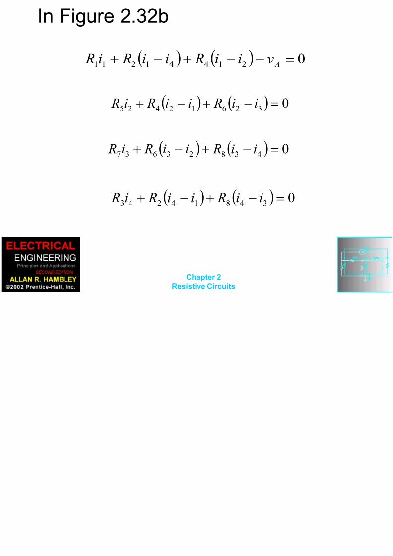
In Figure 2.32b
021441211 Avii Rii Ri R
032612425 ii Rii Ri R
043823637 ii Rii Ri R
034814243 ii Rii Ri R
8/14/2019 Chapter 02-1.ppt
http://slidepdf.com/reader/full/chapter-02-1ppt 58/101
Chapter 2Resistive Circuits
8/14/2019 Chapter 02-1.ppt
http://slidepdf.com/reader/full/chapter-02-1ppt 59/101
Chapter 2Resistive Circuits
M h C i Ci i

8/14/2019 Chapter 02-1.ppt
http://slidepdf.com/reader/full/chapter-02-1ppt 60/101
Chapter 2Resistive Circuits
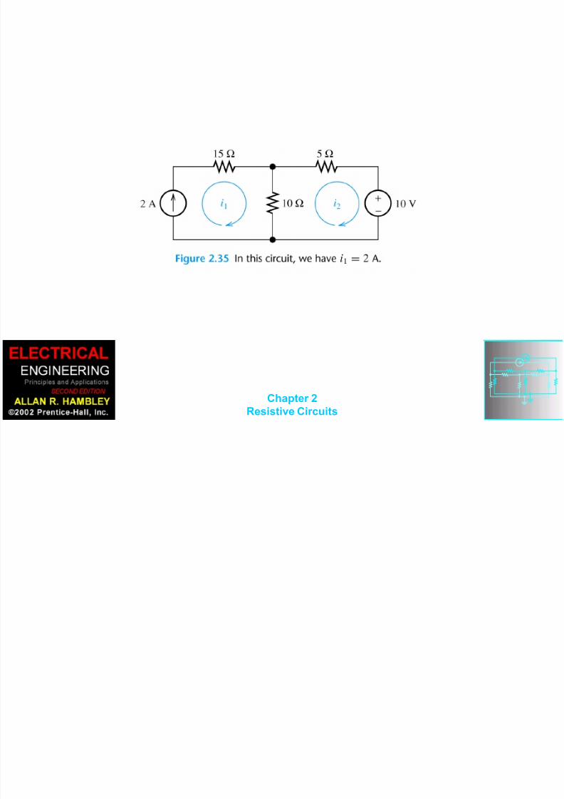
Mesh Currents in Circuits
Containing Current Sources
A common mistake made by beginning
students is to assume that the voltages
across current sources are zero. InFigure 2.35, we have:
A21 i
0105)(10 212 iii
8/14/2019 Chapter 02-1.ppt
http://slidepdf.com/reader/full/chapter-02-1ppt 61/101
Chapter 2Resistive Circuits

8/14/2019 Chapter 02-1.ppt
http://slidepdf.com/reader/full/chapter-02-1ppt 62/101
Chapter 2Resistive Circuits
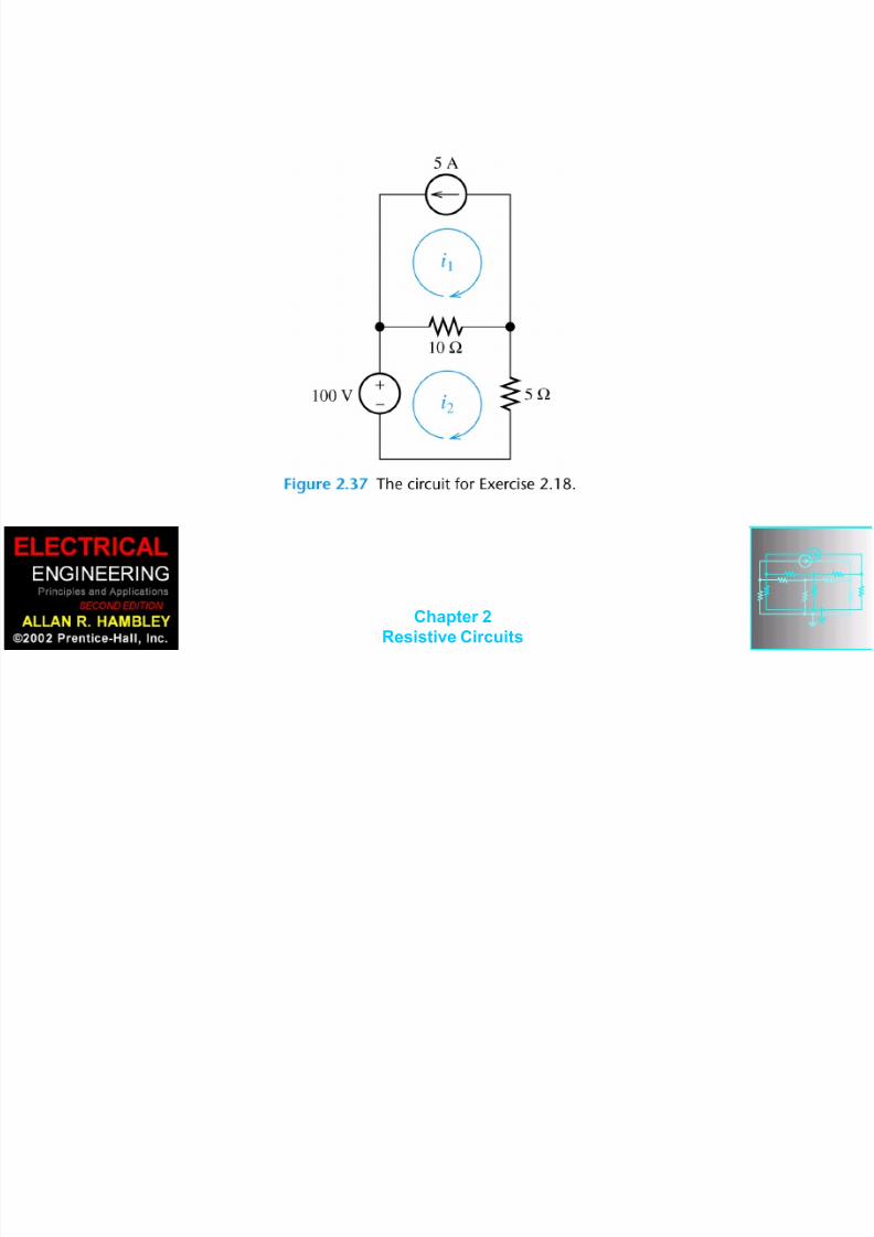
Combine meshes 1 and 2 into a supermesh In other

8/14/2019 Chapter 02-1.ppt
http://slidepdf.com/reader/full/chapter-02-1ppt 63/101
Chapter 2Resistive Circuits
Combine meshes 1 and 2 into a supermesh. In other
words, we write a KVL equation around the periphery of
meshes 1 and 2 combined.
01042 32311 iiiii
Mesh 3:
0243 13233 iiiii
512 ii
8/14/2019 Chapter 02-1.ppt
http://slidepdf.com/reader/full/chapter-02-1ppt 64/101
Chapter 2Resistive Circuits

8/14/2019 Chapter 02-1.ppt
http://slidepdf.com/reader/full/chapter-02-1ppt 65/101
Chapter 2Resistive Circuits

8/14/2019 Chapter 02-1.ppt
http://slidepdf.com/reader/full/chapter-02-1ppt 66/101
Chapter 2Resistive Circuits
8/14/2019 Chapter 02-1.ppt
http://slidepdf.com/reader/full/chapter-02-1ppt 67/101
Chapter 2Resistive Circuits
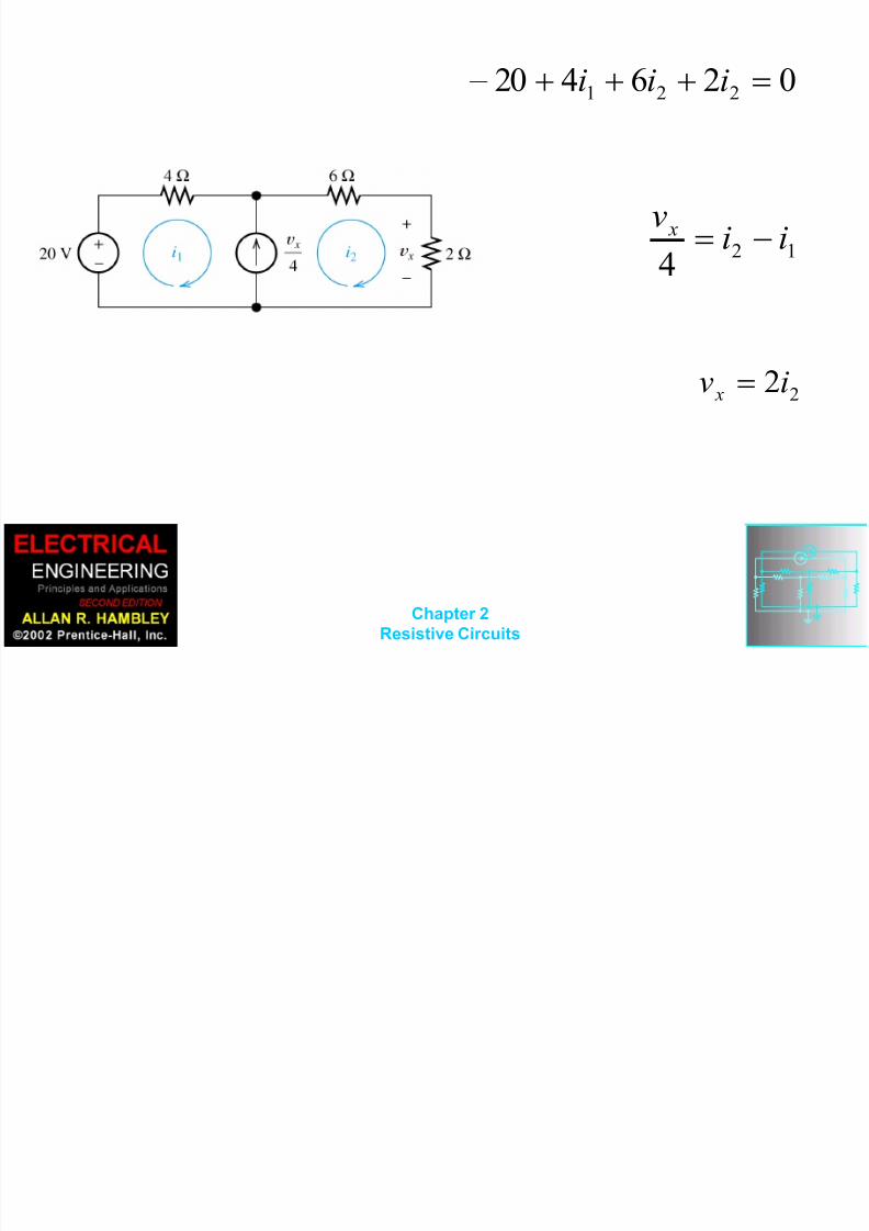
026420 221 iii
124
iiv x
22iv x
M h C t A l i
8/14/2019 Chapter 02-1.ppt
http://slidepdf.com/reader/full/chapter-02-1ppt 68/101
Chapter 2Resistive Circuits
Mesh-Current Analysis
1. If necessary, redraw the network
without crossing conductors or elements.
Then define the mesh currents flowing
around each of the open areas defined
by the network. For consistency, we
usually select a clockwise direction foreach of the mesh currents, but this is not
a requirement.
2 Write network equations stopping after

8/14/2019 Chapter 02-1.ppt
http://slidepdf.com/reader/full/chapter-02-1ppt 69/101
Chapter 2Resistive Circuits
2. Write network equations, stopping after
the number of equations is equal to the
number of mesh currents. First, use KVLto write voltage equations for meshes that
do not contain current sources. Next, if
any current sources are present, writeexpressions for their currents in terms of
the mesh currents. Finally, if a current
source is common to two meshes, write aKVL equation for the supermesh.

8/14/2019 Chapter 02-1.ppt
http://slidepdf.com/reader/full/chapter-02-1ppt 70/101
Chapter 2Resistive Circuits
3. If the circuit contains dependent
sources, find expressions for the
controlling
variables in terms of the mesh currents.
Substitute into the network equations,
and obtain equations having only the
mesh currents as unknowns.
4 Put the equations into standard form

8/14/2019 Chapter 02-1.ppt
http://slidepdf.com/reader/full/chapter-02-1ppt 71/101
Chapter 2Resistive Circuits
4. Put the equations into standard form.
Solve for the mesh currents by use of
determinants or other means.
5. Use the values found for the mesh
currents to calculate any other currentsor voltages of interest.

8/14/2019 Chapter 02-1.ppt
http://slidepdf.com/reader/full/chapter-02-1ppt 72/101
Chapter 2Resistive Circuits
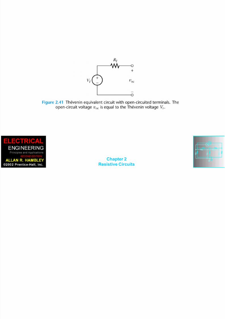
Thévenin Equivalent
Circuits
8/14/2019 Chapter 02-1.ppt
http://slidepdf.com/reader/full/chapter-02-1ppt 73/101
Chapter 2Resistive Circuits

8/14/2019 Chapter 02-1.ppt
http://slidepdf.com/reader/full/chapter-02-1ppt 74/101
Chapter 2Resistive Circuits

8/14/2019 Chapter 02-1.ppt
http://slidepdf.com/reader/full/chapter-02-1ppt 75/101
Chapter 2Resistive Circuits
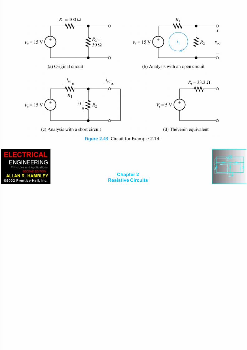
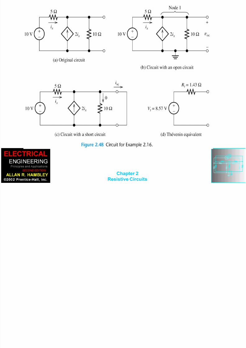
Thévenin Equivalent
Circuits ocvV
t
sc
oc
i
v R
t
8/14/2019 Chapter 02-1.ppt
http://slidepdf.com/reader/full/chapter-02-1ppt 76/101
Chapter 2Resistive Circuits

8/14/2019 Chapter 02-1.ppt
http://slidepdf.com/reader/full/chapter-02-1ppt 77/101
Chapter 2Resistive Circuits
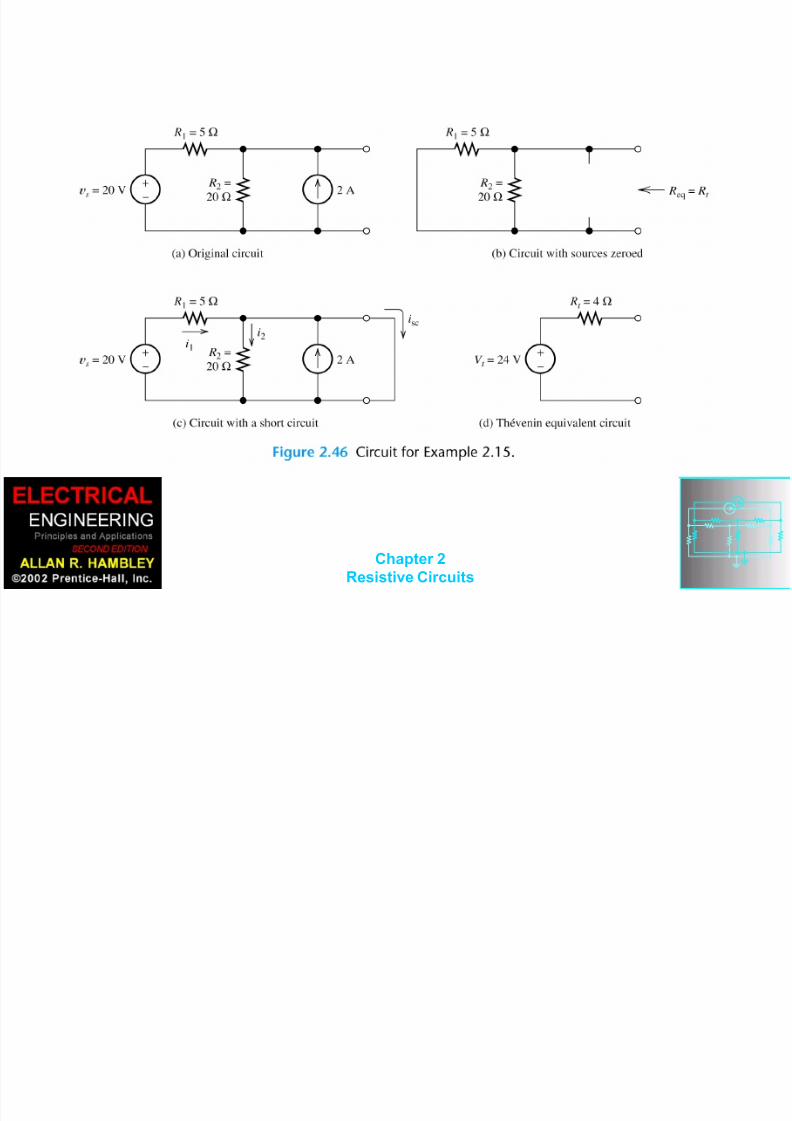
Finding the Thévenin

8/14/2019 Chapter 02-1.ppt
http://slidepdf.com/reader/full/chapter-02-1ppt 78/101
Chapter 2Resistive Circuits
g
Resistance Directly
When zeroing a voltage source, it becomes ashort circuit. When zeroing a current source,
it becomes an open circuit.
We can find the Thévenin resistance by
zeroing the sources in the original network
and then computing the resistance between
the terminals.

8/14/2019 Chapter 02-1.ppt
http://slidepdf.com/reader/full/chapter-02-1ppt 79/101
Chapter 2Resistive Circuits
8/14/2019 Chapter 02-1.ppt
http://slidepdf.com/reader/full/chapter-02-1ppt 80/101
Chapter 2Resistive Circuits
8/14/2019 Chapter 02-1.ppt
http://slidepdf.com/reader/full/chapter-02-1ppt 81/101
Chapter 2Resistive Circuits
8/14/2019 Chapter 02-1.ppt
http://slidepdf.com/reader/full/chapter-02-1ppt 82/101
Chapter 2Resistive Circuits
8/14/2019 Chapter 02-1.ppt
http://slidepdf.com/reader/full/chapter-02-1ppt 83/101
Chapter 2Resistive Circuits

8/14/2019 Chapter 02-1.ppt
http://slidepdf.com/reader/full/chapter-02-1ppt 84/101
Chapter 2Resistive Circuits
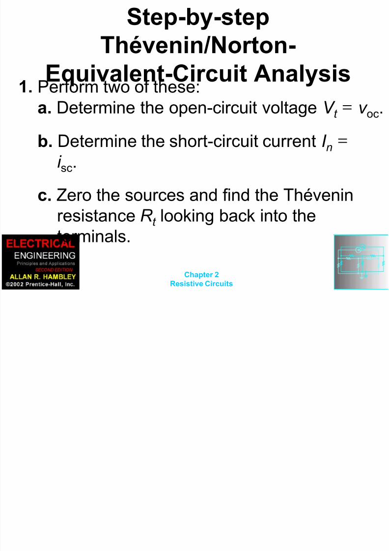
Step-by-step
8/14/2019 Chapter 02-1.ppt
http://slidepdf.com/reader/full/chapter-02-1ppt 85/101
Chapter 2Resistive Circuits
Thévenin/Norton-
Equivalent-Circuit Analysis 1. Perform two of these:
a. Determine the open-circuit voltage V t = v oc.
b. Determine the short-circuit current I n =i sc.
c. Zero the sources and find the Thévenin
resistance R t looking back into theterminals.

8/14/2019 Chapter 02-1.ppt
http://slidepdf.com/reader/full/chapter-02-1ppt 86/101
Chapter 2Resistive Circuits
2. Use the equation V t = R t I n to compute
the remaining value.
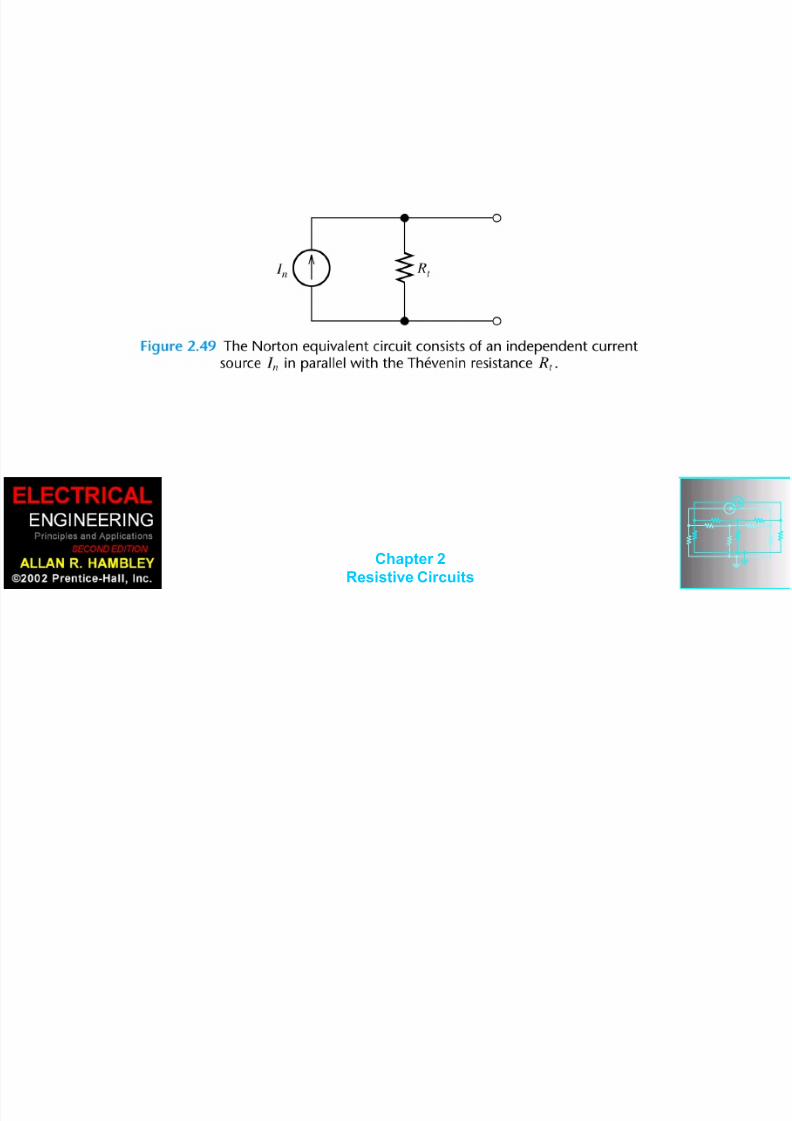
3. The Thévenin equivalent consists of a
voltage source V t in series with R t .
4. The Norton equivalent consists of a
current source I n in parallel with R t .
8/14/2019 Chapter 02-1.ppt
http://slidepdf.com/reader/full/chapter-02-1ppt 87/101
Chapter 2Resistive Circuits

8/14/2019 Chapter 02-1.ppt
http://slidepdf.com/reader/full/chapter-02-1ppt 88/101
Chapter 2Resistive Circuits
8/14/2019 Chapter 02-1.ppt
http://slidepdf.com/reader/full/chapter-02-1ppt 89/101
Chapter 2
Resistive Circuits
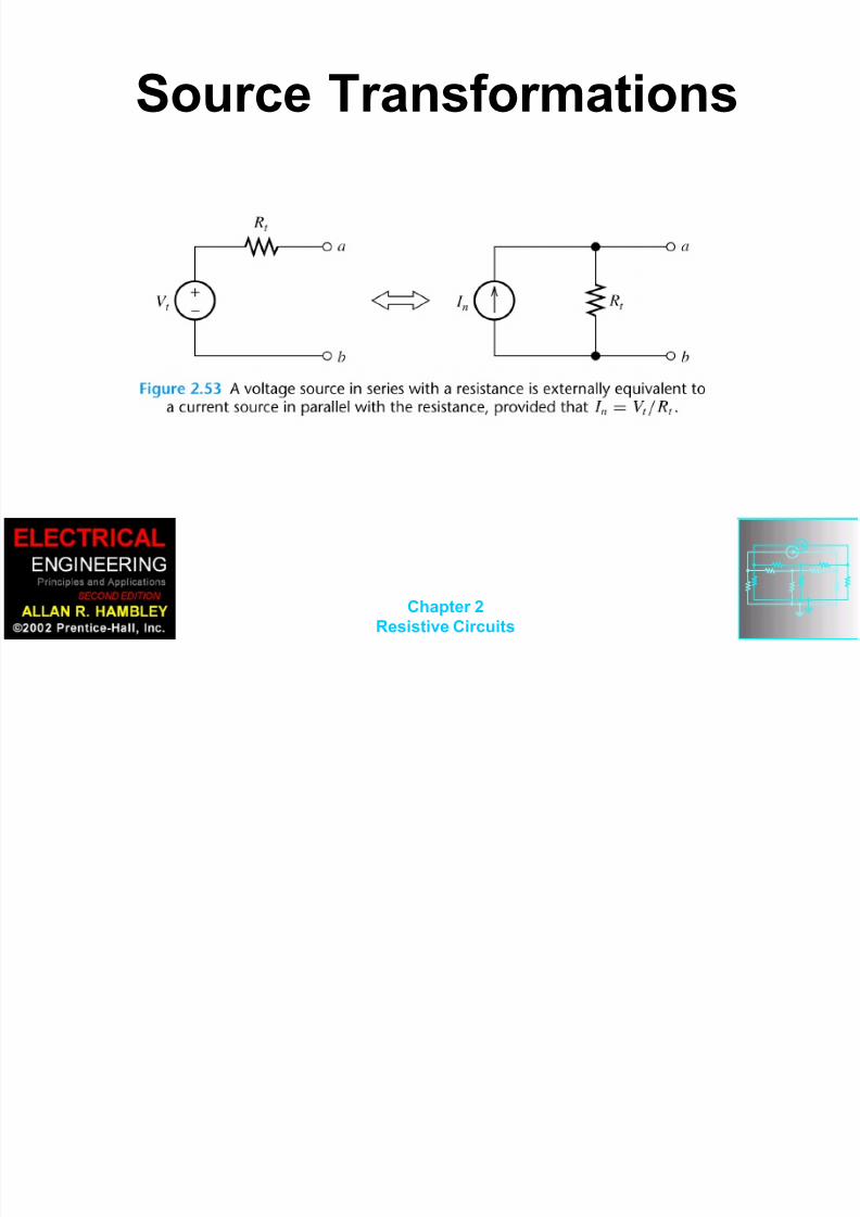
Source Transformations

8/14/2019 Chapter 02-1.ppt
http://slidepdf.com/reader/full/chapter-02-1ppt 90/101
Chapter 2
Resistive Circuits

8/14/2019 Chapter 02-1.ppt
http://slidepdf.com/reader/full/chapter-02-1ppt 91/101
Chapter 2
Resistive Circuits

8/14/2019 Chapter 02-1.ppt
http://slidepdf.com/reader/full/chapter-02-1ppt 92/101
Chapter 2
Resistive Circuits
Maximum Power Transfer
The load resistance that absorbs the
maximum power from a two-terminal
circuit is equal to the Théveninresistance.

8/14/2019 Chapter 02-1.ppt
http://slidepdf.com/reader/full/chapter-02-1ppt 93/101
Chapter 2
Resistive Circuits

8/14/2019 Chapter 02-1.ppt
http://slidepdf.com/reader/full/chapter-02-1ppt 94/101
Chapter 2
Resistive Circuits
SUPERPOSITION
8/14/2019 Chapter 02-1.ppt
http://slidepdf.com/reader/full/chapter-02-1ppt 95/101
Chapter 2
Resistive Circuits
SUPERPOSITION
PRINCIPLE
The superposition principle states
that the total response is the sum of
the responses to each of theindependent sources acting
individually. In equation form, this is
nT r r r r 21

8/14/2019 Chapter 02-1.ppt
http://slidepdf.com/reader/full/chapter-02-1ppt 96/101
Chapter 2
Resistive Circuits

8/14/2019 Chapter 02-1.ppt
http://slidepdf.com/reader/full/chapter-02-1ppt 97/101
Chapter 2
Resistive Circuits

8/14/2019 Chapter 02-1.ppt
http://slidepdf.com/reader/full/chapter-02-1ppt 98/101

8/14/2019 Chapter 02-1.ppt
http://slidepdf.com/reader/full/chapter-02-1ppt 99/101
Chapter 2
Resistive Circuits
8/14/2019 Chapter 02-1.ppt
http://slidepdf.com/reader/full/chapter-02-1ppt 100/101
Chapter 2
Resistive Circuits
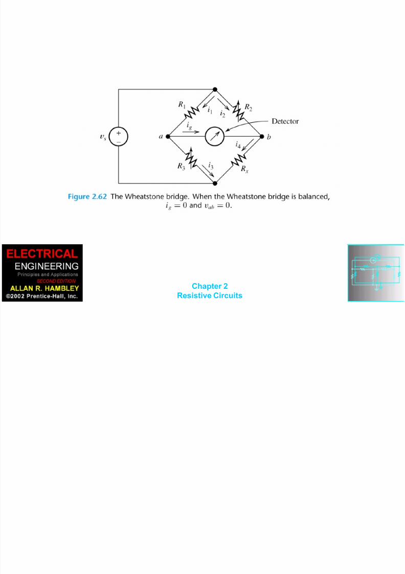
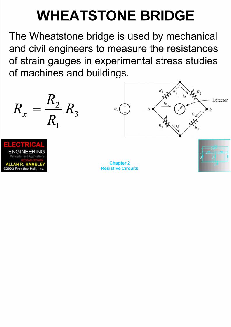
WHEATSTONE BRIDGE
8/14/2019 Chapter 02-1.ppt
http://slidepdf.com/reader/full/chapter-02-1ppt 101/101
The Wheatstone bridge is used by mechanical
and civil engineers to measure the resistancesof strain gauges in experimental stress studies
of machines and buildings.
3
1
2 R
R
R R
x
Recommended