CE 3372 – Lecture 13
OPEN CHANNEL HYDRAULICS

OUTLINE
• Flow Terminology
• Energy Equation
• Critical Depth/Flow
• Flow Profiles for GVF
• Manning’s Equation

OPEN CHANNEL DESIGN CONCEPTS
• Interest to engineers:• Water surface elevation (WSE)
(minimize impact/reduce floods)
• Discharge –Depth relationships
• Channel design

OPEN CHANNELS
• Conduits whose upper boundary of flow is the liquid surface.

TYPES OF FLOW• Steady Flow – flow, depth and velocity may differ from point to point but
remain constant over time
• Unsteady Flow – flow, depth, and velocity is a function of time
• Uniform Flow – occurs in prismatic channels when flow depths are equalno change in velocity within the channel: Q, y, A, S are all
constant
• Non-uniform Flow – velocity is not the same at every point
Temporal
Spatial


OPEN CHANNEL NOMENCLATURE
• Flow depth is the depth of flow at a cross-section measured from the channel bottom.
y

OPEN CHANNEL NOMENCLATURE
• Elevation of the channel bottom is the elevation at a cross-section measured from a reference datum (typically MSL).
y
Datum
z

OPEN CHANNEL NOMENCLATURE
• Slope of the channel bottom, So, is called the topographic slope or channel slope.
y
Datum
So
1z

OPEN CHANNEL NOMENCLATURE
• Slope of the water surface is the slope of the HGL, or slope of WSE (water surface elevation).
y
Datum
So
1z
1Swse
HGL

OPEN CHANNEL NOMENCLATURE
• Slope of the energy grade line (EGL) is called the energy or friction slope.
y
Datum
So
1z
1Swse
HGL
EGL
1SfV2/2g
Q=VA

STEADY NON-UNIFORM FLOW
Sketch of steady flow in a channel
Based on cross-sections: Section 1 is upstream Section 2 is downstream

STEADY FLOWThe energy grade line (EGL) is: z_head + P_head + v_head
elevation
pressure (depth)
velocity
Sketch of steady flow in a channel
The hydraulic grade line (HGL) is at the water surface
Hydraulic grade line (HGL)
Energy grade line (EGL) Profile grade line is the channel bottom
The head loss is depicted as the differencebetween a horizontal zero-loss energy grade line and the energy grade line


ENERGY RELATIONSHIPS
• Energy equation for closed conduits
• Energy equation for open conduits
2 21 1 2 2
1 1 2 22 2 L
p V p Vz z h
g ga a
g g+ + = + + +
2 21 2
1 22 2o f
V Vy S x y S x
g g+ D + = + + D

SPECIFIC ENERGY
• The sum of the depth of flow + velocity head (Head relative to the channel bottom)
• For a given discharge, the SE can be calculated for various flow depths including critical depth
g
VyE
2
2

CRITICAL DEPTH
• Depth of flow for a given discharge, where the specific energy is at a minimum
• Occurs when dE/dy = 0 and Fr = 1
• It is important to calculate yc in order to determine if the flow in the channel will be subcritical or supercritical
• Can be found through Specific Energy Diagram

2
2
2gA
QyE
A = By
B
y
Alternate Depths:
Q=qywhere q is the discharge/unit width of channel
Plug & chug. Solve for y
3 roots –1 negative = 2 depths

OPEN CHANNEL FLOWS
• Open channel flow is also classified by the Froude number
• Critical depth, yc occurs at Fr = 1

OPEN CHANNEL FLOWS
Subcritical flow• Low velocities, Fr < 1• Disturbance travels upstream• y > yc
Supercritical flow• High velocities, Fr > 1• Disturbances travel
downstream• y < yc

PA
CRITICAL FLOWT
dy
yHas a minimum at yc
2
2
2gA
QyE 0
dy
dE
dA=
0dEdy
= =
3
2
1c
c
gA
TQ
Arbitrary cross-section
22
FrgA
TV
dA
AD
T=
2
31Q dAgA dy
-
Tdy More general definition of Fr

CRITICAL FLOW – RECTANGULAR CHANNEL
yc
T
Ac
3
2
1c
c
gA
TQ
qTQ TyA cc
3
2
33
32
1cc gy
q
Tgy
Tq
3/12
g
qyc
3cgyq
Only for rectangular channels!
cTT
Given the depth we can find the flow!
qTQ
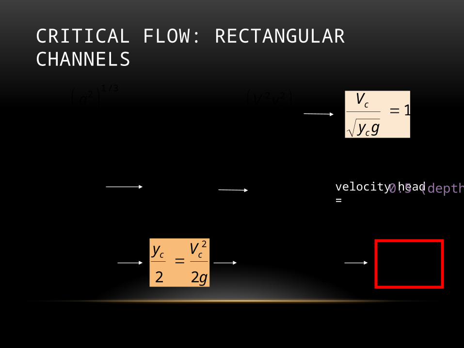
CRITICAL FLOW: RECTANGULAR CHANNELS3/1
2
g
qyc cc yVq
g
yVy ccc
223
g
Vy cc
2
1gy
V
c
cvelocity head =
g
Vy cc
22
2
2
cc
yyE Eyc
3
2
0.5 (depth)
g
VyE
2
2
g
Vy cc
22
2
1gy
V
c
c

OPEN CHANNEL FLOWS• Similar to pipe flow, open channel flow can be classified into
which is dependent on Reynolds number
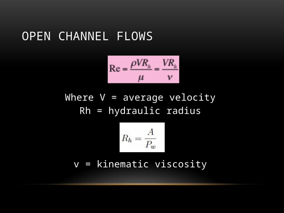
OPEN CHANNEL FLOWS
Where V = average velocityRh = hydraulic radius
v = kinematic viscosity
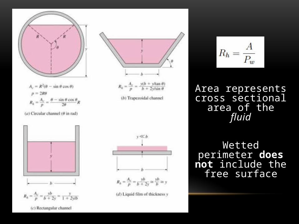
Area represents cross sectional area of the
fluid
Wetted perimeter does not include the
free surface

RECTANGULAR CONDUIT
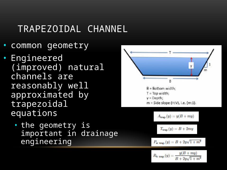
TRAPEZOIDAL CHANNEL
• common geometry• Engineered (improved)
natural channels are reasonably well approximated by trapezoidal equations• the geometry is important in
drainage engineering

CIRCULAR CONDUIT
• Sweep angle definition matters, book uses 2a.

VARIED FLOW• Gradually varied flow – change in flow depth moving upstream
or downstream is gradual• Rapidly varied flow – change in flow depth occurs over a very
short distance• Ex: waterfall, hydraulic jumps, etc.
• RVF is outside the scope of this course.

GRADUALLY VARIED FLOW
• Equation relating slope of water surface, channel slope, and energy slope:
Variation of Water Surface Elevation
Discharge and Section Geometry
Discharge and Section Geometry

GRADUALLY VARIED FLOW• Procedure to find water surface profile is to integrate the depth taper with distance:

FLOW PROFILESSLOPE DEPTH RELATIONSHIP
Steep yn < yc
Critical yn = yc
Mild yn > yc
Horizontal S0 = 0
Adverse S0 < 0
PROFILE TYPE DEPTH RELATIONSHIP
Type-1 y > yc AND y > yn
Type -2 yc < y < yn OR yn < y < yn
Type -3 y < yc AND y < yn


MANNING EQUATION (1891)
• Depth-Discharge Calculator for any open channel implements Manning's equation
• The equation is the U.S. customary version• A drainage engineer in the US should memorize this
equation!

VALUES OF MANNING N
Lined Canals n Cement plaster 0.011 Untreated gunite 0.016 Wood, planed 0.012 Wood, unplaned 0.013 Concrete, trowled 0.012 Concrete, wood forms, unfinished 0.015 Rubble in cement 0.020 Asphalt, smooth 0.013 Asphalt, rough 0.016
Natural Channels Gravel beds, straight 0.025 Gravel beds plus large boulders 0.040 Earth, straight, with some grass 0.026 Earth, winding, no vegetation 0.030 Earth , winding with vegetation 0.050
d = median size of bed material
n = f(surface roughness, channel irregularity, stage...)
6/1031.0 dn d in ft

SUMMARY OF OPEN CHANNELS
• All the complications of pipe flow plus ______________________
• Importance of Froude Number
• Fr>1 decrease in E gives increase in y
• Fr<1 decrease in E gives decrease in y
• Fr=1 standing waves (also min E given Q)
free surface location
Recommended