SPECIFICATIONS
cDAQ™-91854-Slot, Extended Temperature, Ethernet CompactDAQ Chassis
DefinitionsWarranted specifications describe the performance of a model under stated operatingconditions and are covered by the model warranty.
Characteristics describe values that are relevant to the use of the model under stated operatingconditions but are not covered by the model warranty.• Typical specifications describe the expected performance met by a majority of the
models.• Nominal specifications describe parameters and attributes that may be useful in operation.
Specifications are Typical unless otherwise noted.
ConditionsSpecifications are valid at 25 °C unless otherwise noted.
Analog InputInput FIFO size 127 samples per slot
Maximum sample rate1 Determined by the C Series module or modules
Timing accuracy2 50 ppm of sample rate
Internal base clocks 80 MHz, 20 MHz, 13.1072 MHz, 12.8 MHz,10 MHz, 100 kHz
Number of channels supported Determined by the C Series module or modules
1 Performance dependent on type of installed C Series module and number of channels in the task.2 Does not include group delay. For more information, refer to the documentation for each C Series
module.
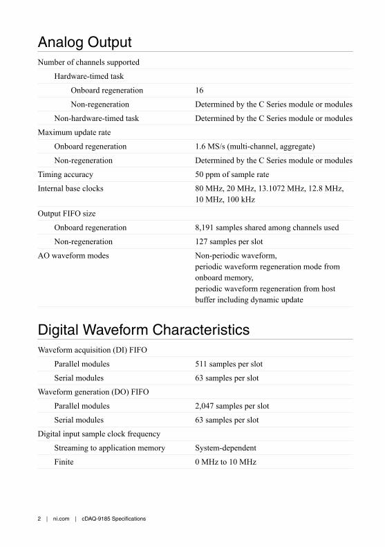
Analog OutputNumber of channels supported
Hardware-timed task
Onboard regeneration 16
Non-regeneration Determined by the C Series module or modules
Non-hardware-timed task Determined by the C Series module or modules
Maximum update rate
Onboard regeneration 1.6 MS/s (multi-channel, aggregate)
Non-regeneration Determined by the C Series module or modules
Timing accuracy 50 ppm of sample rate
Internal base clocks 80 MHz, 20 MHz, 13.1072 MHz, 12.8 MHz,10 MHz, 100 kHz
Output FIFO size
Onboard regeneration 8,191 samples shared among channels used
Non-regeneration 127 samples per slot
AO waveform modes Non-periodic waveform,periodic waveform regeneration mode fromonboard memory,periodic waveform regeneration from hostbuffer including dynamic update
Digital Waveform CharacteristicsWaveform acquisition (DI) FIFO
Parallel modules 511 samples per slot
Serial modules 63 samples per slotWaveform generation (DO) FIFO
Parallel modules 2,047 samples per slot
Serial modules 63 samples per slotDigital input sample clock frequency
Streaming to application memory System-dependent
Finite 0 MHz to 10 MHz
2 | ni.com | cDAQ-9185 Specifications
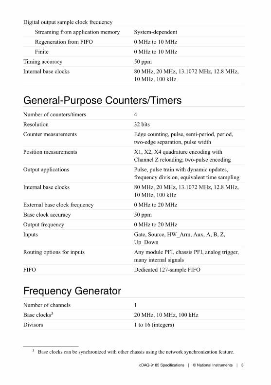
Digital output sample clock frequency
Streaming from application memory System-dependent
Regeneration from FIFO 0 MHz to 10 MHz
Finite 0 MHz to 10 MHz
Timing accuracy 50 ppmInternal base clocks 80 MHz, 20 MHz, 13.1072 MHz, 12.8 MHz,
10 MHz, 100 kHz
General-Purpose Counters/TimersNumber of counters/timers 4
Resolution 32 bits
Counter measurements Edge counting, pulse, semi-period, period,two-edge separation, pulse width
Position measurements X1, X2, X4 quadrature encoding withChannel Z reloading; two-pulse encoding
Output applications Pulse, pulse train with dynamic updates,frequency division, equivalent time sampling
Internal base clocks 80 MHz, 20 MHz, 13.1072 MHz, 12.8 MHz,10 MHz, 100 kHz
External base clock frequency 0 MHz to 20 MHz
Base clock accuracy 50 ppm
Output frequency 0 MHz to 20 MHz
Inputs Gate, Source, HW_Arm, Aux, A, B, Z,Up_Down
Routing options for inputs Any module PFI, chassis PFI, analog trigger,many internal signals
FIFO Dedicated 127-sample FIFO
Frequency GeneratorNumber of channels 1
Base clocks3 20 MHz, 10 MHz, 100 kHz
Divisors 1 to 16 (integers)
3 Base clocks can be synchronized with other chassis using the network synchronization feature.
cDAQ-9185 Specifications | © National Instruments | 3
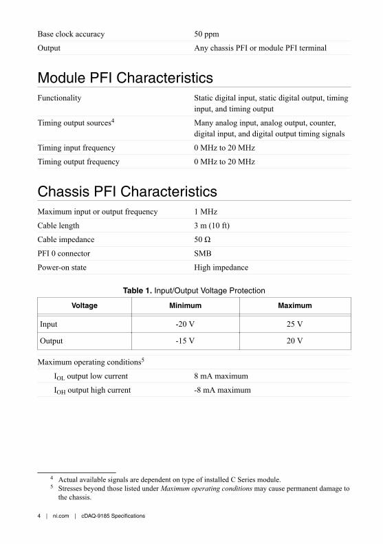
Base clock accuracy 50 ppm
Output Any chassis PFI or module PFI terminal
Module PFI CharacteristicsFunctionality Static digital input, static digital output, timing
input, and timing output
Timing output sources4 Many analog input, analog output, counter,digital input, and digital output timing signals
Timing input frequency 0 MHz to 20 MHz
Timing output frequency 0 MHz to 20 MHz
Chassis PFI CharacteristicsMaximum input or output frequency 1 MHz
Cable length 3 m (10 ft)
Cable impedance 50 Ω
PFI 0 connector SMB
Power-on state High impedance
Table 1. Input/Output Voltage Protection
Voltage Minimum Maximum
Input -20 V 25 V
Output -15 V 20 V
Maximum operating conditions5
IOL output low current 8 mA maximum
IOH output high current -8 mA maximum
4 Actual available signals are dependent on type of installed C Series module.5 Stresses beyond those listed under Maximum operating conditions may cause permanent damage to
the chassis.
4 | ni.com | cDAQ-9185 Specifications
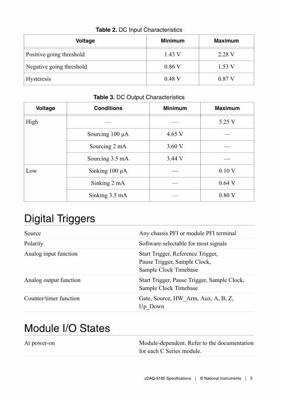
Table 2. DC Input Characteristics
Voltage Minimum Maximum
Positive going threshold 1.43 V 2.28 V
Negative going threshold 0.86 V 1.53 V
Hysteresis 0.48 V 0.87 V
Table 3. DC Output Characteristics
Voltage Conditions Minimum Maximum
High — — 5.25 V
Sourcing 100 μA 4.65 V —
Sourcing 2 mA 3.60 V —
Sourcing 3.5 mA 3.44 V —
Low Sinking 100 μA — 0.10 V
Sinking 2 mA — 0.64 V
Sinking 3.5 mA — 0.80 V
Digital TriggersSource Any chassis PFI or module PFI terminal
Polarity Software-selectable for most signals
Analog input function Start Trigger, Reference Trigger,Pause Trigger, Sample Clock,Sample Clock Timebase
Analog output function Start Trigger, Pause Trigger, Sample Clock,Sample Clock Timebase
Counter/timer function Gate, Source, HW_Arm, Aux, A, B, Z,Up_Down
Module I/O StatesAt power-on Module-dependent. Refer to the documentation
for each C Series module.
cDAQ-9185 Specifications | © National Instruments | 5
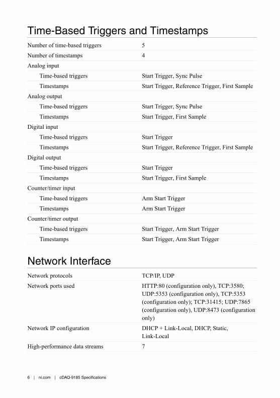
Time-Based Triggers and TimestampsNumber of time-based triggers 5
Number of timestamps 4
Analog input
Time-based triggers Start Trigger, Sync Pulse
Timestamps Start Trigger, Reference Trigger, First Sample
Analog output
Time-based triggers Start Trigger, Sync Pulse
Timestamps Start Trigger, First Sample
Digital input
Time-based triggers Start Trigger
Timestamps Start Trigger, Reference Trigger, First Sample
Digital output
Time-based triggers Start Trigger
Timestamps Start Trigger, First Sample
Counter/timer input
Time-based triggers Arm Start Trigger
Timestamps Arm Start Trigger
Counter/timer output
Time-based triggers Start Trigger, Arm Start Trigger
Timestamps Start Trigger, Arm Start Trigger
Network InterfaceNetwork protocols TCP/IP, UDP
Network ports used HTTP:80 (configuration only), TCP:3580;UDP:5353 (configuration only), TCP:5353(configuration only); TCP:31415; UDP:7865(configuration only), UDP:8473 (configurationonly)
Network IP configuration DHCP + Link-Local, DHCP, Static,Link-Local
High-performance data streams 7
6 | ni.com | cDAQ-9185 Specifications
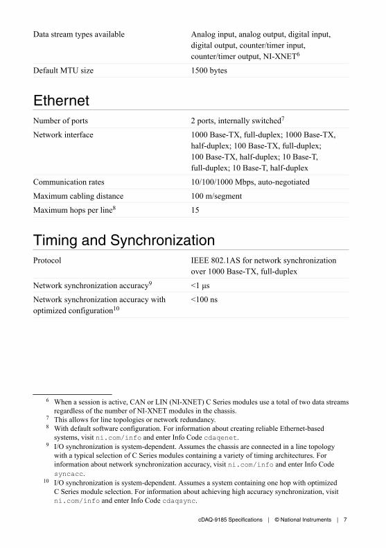
Data stream types available Analog input, analog output, digital input,digital output, counter/timer input,counter/timer output, NI-XNET6
Default MTU size 1500 bytes
EthernetNumber of ports 2 ports, internally switched7
Network interface 1000 Base-TX, full-duplex; 1000 Base-TX,half-duplex; 100 Base-TX, full-duplex;100 Base-TX, half-duplex; 10 Base-T,full-duplex; 10 Base-T, half-duplex
Communication rates 10/100/1000 Mbps, auto-negotiated
Maximum cabling distance 100 m/segment
Maximum hops per line8 15
Timing and SynchronizationProtocol IEEE 802.1AS for network synchronization
over 1000 Base-TX, full-duplex
Network synchronization accuracy9 <1 μs
Network synchronization accuracy withoptimized configuration10
<100 ns
6 When a session is active, CAN or LIN (NI-XNET) C Series modules use a total of two data streamsregardless of the number of NI-XNET modules in the chassis.
7 This allows for line topologies or network redundancy.8 With default software configuration. For information about creating reliable Ethernet-based
systems, visit ni.com/info and enter Info Code cdaqenet.9 I/O synchronization is system-dependent. Assumes the chassis are connected in a line topology
with a typical selection of C Series modules containing a variety of timing architectures. Forinformation about network synchronization accuracy, visit ni.com/info and enter Info Codesyncacc.
10 I/O synchronization is system-dependent. Assumes a system containing one hop with optimizedC Series module selection. For information about achieving high accuracy synchronization, visitni.com/info and enter Info Code cdaqsync.
cDAQ-9185 Specifications | © National Instruments | 7
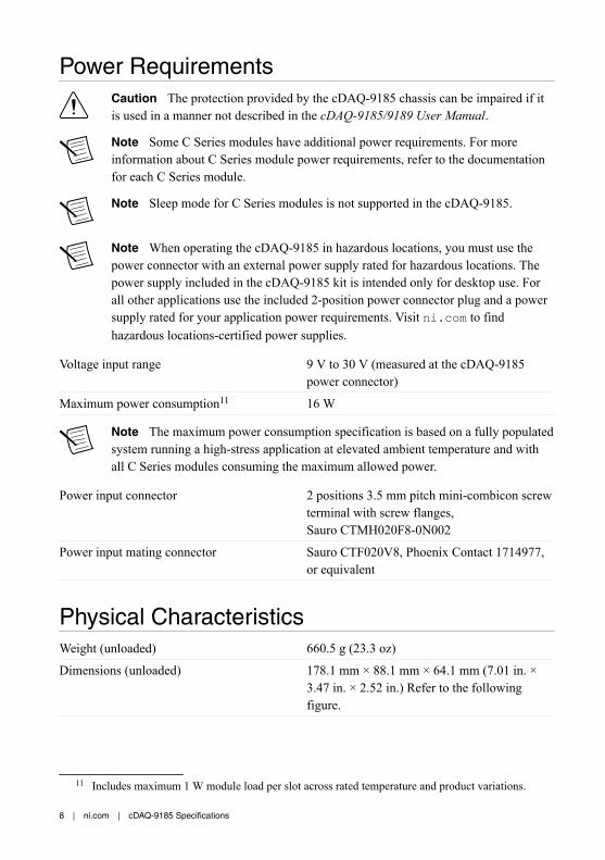
Power RequirementsCaution The protection provided by the cDAQ-9185 chassis can be impaired if itis used in a manner not described in the cDAQ-9185/9189 User Manual.
Note Some C Series modules have additional power requirements. For moreinformation about C Series module power requirements, refer to the documentationfor each C Series module.
Note Sleep mode for C Series modules is not supported in the cDAQ-9185.
Note When operating the cDAQ-9185 in hazardous locations, you must use thepower connector with an external power supply rated for hazardous locations. Thepower supply included in the cDAQ-9185 kit is intended only for desktop use. Forall other applications use the included 2-position power connector plug and a powersupply rated for your application power requirements. Visit ni.com to findhazardous locations-certified power supplies.
Voltage input range 9 V to 30 V (measured at the cDAQ-9185power connector)
Maximum power consumption11 16 W
Note The maximum power consumption specification is based on a fully populatedsystem running a high-stress application at elevated ambient temperature and withall C Series modules consuming the maximum allowed power.
Power input connector 2 positions 3.5 mm pitch mini-combicon screwterminal with screw flanges,Sauro CTMH020F8-0N002
Power input mating connector Sauro CTF020V8, Phoenix Contact 1714977,or equivalent
Physical CharacteristicsWeight (unloaded) 660.5 g (23.3 oz)
Dimensions (unloaded) 178.1 mm × 88.1 mm × 64.1 mm (7.01 in. ×3.47 in. × 2.52 in.) Refer to the followingfigure.
11 Includes maximum 1 W module load per slot across rated temperature and product variations.
8 | ni.com | cDAQ-9185 Specifications
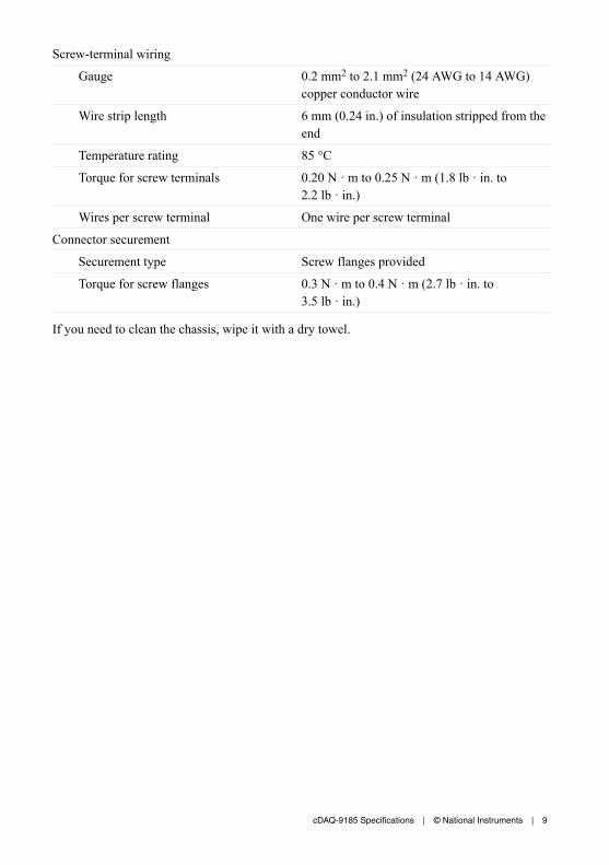
Screw-terminal wiring
Gauge 0.2 mm2 to 2.1 mm2 (24 AWG to 14 AWG)copper conductor wire
Wire strip length 6 mm (0.24 in.) of insulation stripped from theend
Temperature rating 85 °C
Torque for screw terminals 0.20 N · m to 0.25 N · m (1.8 lb · in. to2.2 lb · in.)
Wires per screw terminal One wire per screw terminal
Connector securement
Securement type Screw flanges provided
Torque for screw flanges 0.3 N · m to 0.4 N · m (2.7 lb · in. to3.5 lb · in.)
If you need to clean the chassis, wipe it with a dry towel.
cDAQ-9185 Specifications | © National Instruments | 9
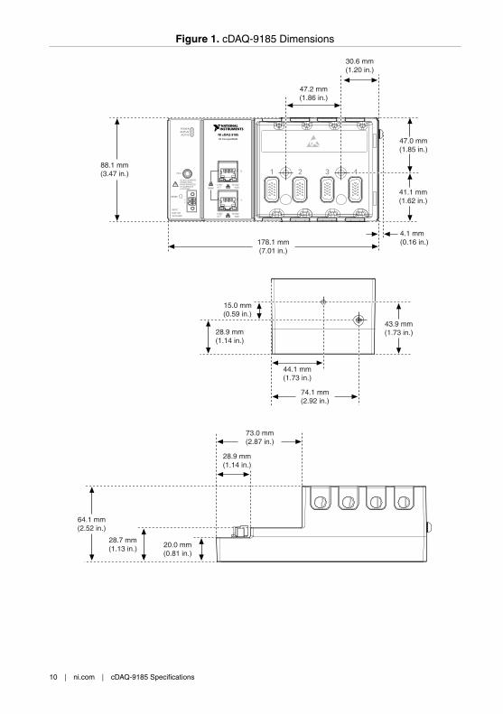
Figure 1. cDAQ-9185 Dimensions
43.9 mm(1.73 in.)
44.1 mm(1.73 in.)
74.1 mm(2.92 in.)
15.0 mm(0.59 in.)
28.9 mm(1.14 in.)
NI CompactDAQ
NI cDAQ-9185
POWERSTATUS
PFI 0
RESET
DO NOT SEPARATE CONNECTORS WHEN ENERGIZED IN HAZARDOUS LOCATIONS
21
ACTIVE
43
INPUT
9-30 V16 W MAX
88.1 mm(3.47 in.)
47.2 mm(1.86 in.)
47.0 mm(1.85 in.)
41.1 mm(1.62 in.)
30.6 mm(1.20 in.)
4.1 mm(0.16 in.)178.1 mm
(7.01 in.)
64.1 mm(2.52 in.)
20.0 mm(0.81 in.)
28.9 mm(1.14 in.)
73.0 mm(2.87 in.)
28.7 mm(1.13 in.)
LINK/ACT
10/100/1000
1
2
LINK/ACT
10/100/1000
SYNC
10 | ni.com | cDAQ-9185 Specifications
Safety VoltagesConnect only voltages that are within these limits.
V terminal to C terminal 30 V maximum, Measurement Category I
Measurement Category I is for measurements performed on circuits not directly connected tothe electrical distribution system referred to as MAINS voltage. MAINS is a hazardous liveelectrical supply system that powers equipment. This category is for measurements of voltagesfrom specially protected secondary circuits. Such voltage measurements include signal levels,special equipment, limited-energy parts of equipment, circuits powered by regulatedlow-voltage sources, and electronics.
Caution Do not connect the system to signals or use for measurements withinMeasurement Categories II, III, or IV.
Note Measurement Categories CAT I and CAT O (Other) are equivalent. These testand measurement circuits are not intended for direct connection to the MAINsbuilding installations of Measurement Categories CAT II, CAT III, or CAT IV.
EnvironmentalOperating temperature (IEC 60068-2-1and IEC 60068-2-2)
-40 °C to 70 °C12
Note Failure to follow the mounting instructions in the cDAQ-9185/9189 UserManual can cause temperature derating.
Storage temperature (IEC 60068-2-1 andIEC 60068-2-2)
-40 °C to 85 °C
Ingress protection IP 40
Operating humidity (IEC 60068-2-56) 10% to 90% RH, noncondensing
Storage humidity (IEC 60068-2-56) 5% to 95% RH, noncondensingPollution Degree (IEC 60664) 2
Maximum altitude 5,000 m
Indoor use only.13
12 When operating the cDAQ-9185 in temperatures below 0 °C, you must use the PS-15 power supplyor another power supply rated for below 0 °C.
13 Use NI 9917 and NI 9918 industrial enclosures to protect the device in harsh, dirty, or wetenvironments.
cDAQ-9185 Specifications | © National Instruments | 11
Hazardous LocationsU.S. (UL) Class I, Division 2, Groups A, B, C, D, T4;
Class I, Zone 2, AEx nA IIC T4 Gc
Canada (C-UL) Class I, Division 2, Groups A, B, C, D, T4; ExnA IIC T4 Gc
Europe (ATEX) and International (IECEx) Ex nA IIC T4 Gc
Shock and VibrationTo meet these specifications, you must direct mount the cDAQ-9185 system and affix ferrulesto the ends of the terminal lines.
Operating vibration
Random (IEC 60068-2-64) 5 g RMS, 10 Hz to 500 Hz
Sinusoidal (IEC 60068-2-6) 5 g, 10 Hz to 500 Hz
Operating shock (IEC 60068-2-27) 30 g, 11 ms half sine,50 g, 3 ms half sine,18 shocks at 6 orientations
Safety and Hazardous Locations StandardsThis product is designed to meet the requirements of the following electrical equipment safetystandards for measurement, control, and laboratory use:• IEC 61010-1, EN 61010-1• UL 61010-1, CSA C22.2 No. 61010-1• EN 60079-0:2012, EN 60079-15:2010• IEC 60079-0: Ed 6, IEC 60079-15; Ed 4• UL 60079-0; Ed 6, UL 60079-15; Ed 4• CSA C22.2 No. 60079-0, CSA C22.2 No. 60079-15
Note For UL and other safety certifications, refer to the product label or the OnlineProduct Certification section.
12 | ni.com | cDAQ-9185 Specifications
Electromagnetic CompatibilityThis product meets the requirements of the following EMC standards for electrical equipmentfor measurement, control, and laboratory use:• EN 61326-1 (IEC 61326-1): Class A emissions; Industrial immunity• EN 55011 (CISPR 11): Group 1, Class A emissions• EN 55022 (CISPR 22): Class A emissions• EN 55024 (CISPR 24): Immunity• AS/NZS CISPR 11: Group 1, Class A emissions• AS/NZS CISPR 22: Class A emissions• FCC 47 CFR Part 15B: Class A emissions• ICES-001: Class A emissions
Note In the United States (per FCC 47 CFR), Class A equipment is intended foruse in commercial, light-industrial, and heavy-industrial locations. In Europe,Canada, Australia and New Zealand (per CISPR 11) Class A equipment is intendedfor use only in heavy-industrial locations.
Note Group 1 equipment (per CISPR 11) is any industrial, scientific, or medicalequipment that does not intentionally generate radio frequency energy for thetreatment of material or inspection/analysis purposes.
Note For EMC declarations and certifications, and additional information, refer tothe Online Product Certification section.
CE Compliance This product meets the essential requirements of applicable European Directives, as follows:• 2014/35/EU; Low-Voltage Directive (safety)• 2014/30/EU; Electromagnetic Compatibility Directive (EMC)• 2014/34/EU; Potentially Explosive Atmospheres (ATEX)
Online Product CertificationRefer to the product Declaration of Conformity (DoC) for additional regulatory complianceinformation. To obtain product certifications and the DoC for this product, visit ni.com/certification, search by model number or product line, and click the appropriate link in theCertification column.
cDAQ-9185 Specifications | © National Instruments | 13

Environmental ManagementNI is committed to designing and manufacturing products in an environmentally responsiblemanner. NI recognizes that eliminating certain hazardous substances from our products isbeneficial to the environment and to NI customers.
For additional environmental information, refer to the Minimize Our Environmental Impactweb page at ni.com/environment. This page contains the environmental regulations anddirectives with which NI complies, as well as other environmental information not included inthis document.
Waste Electrical and Electronic Equipment (WEEE)EU Customers At the end of the product life cycle, all NI products must bedisposed of according to local laws and regulations. For more information abouthow to recycle NI products in your region, visit ni.com/environment/weee.
电子信息产品污染控制管理办法(中国 RoHS)中国客户 National Instruments 符合中国电子信息产品中限制使用某些有害物
质指令(RoHS)。关于 National Instruments 中国 RoHS 合规性信息,请登录
ni.com/environment/rohs_china。(For information about China RoHScompliance, go to ni.com/environment/rohs_china.)
Information is subject to change without notice. Refer to the NI Trademarks and Logo Guidelines at ni.com/trademarks forinformation on NI trademarks. Other product and company names mentioned herein are trademarks or trade names of theirrespective companies. For patents covering NI products/technology, refer to the appropriate location: Help»Patents in yoursoftware, the patents.txt file on your media, or the National Instruments Patent Notice at ni.com/patents. You can findinformation about end-user license agreements (EULAs) and third-party legal notices in the readme file for your NI product. Referto the Export Compliance Information at ni.com/legal/export-compliance for the NI global trade compliance policy and howto obtain relevant HTS codes, ECCNs, and other import/export data. NI MAKES NO EXPRESS OR IMPLIED WARRANTIES ASTO THE ACCURACY OF THE INFORMATION CONTAINED HEREIN AND SHALL NOT BE LIABLE FOR ANY ERRORS. U.S.Government Customers: The data contained in this manual was developed at private expense and is subject to the applicablelimited rights and restricted data rights as set forth in FAR 52.227-14, DFAR 252.227-7014, and DFAR 252.227-7015.
© 2017 National Instruments. All rights reserved.
376606A-01 May 11, 2017
Recommended