Publication No.: AA52192013-01-10
Supersedes: 9J19672012-06-12
CARESTREAM DRX-1 System User Guide
AA5219 | 2013-01-10 1
CARESTREAM DRX-1 System
Publication Number AA5219
Revision A
The information contained herein is based on the experience and knowledge relating to the subject matter gained by Carestream Health, Inc. prior to publication.
No patent license is granted by this information.
Carestream Health reserves the right to change this information without notice, and makes no warranty, express or implied, with respect to this information. Carestream Health shall not be liable for any loss or damage, including consequential or special damages, resulting from any use of this information, even if loss or damage is caused by Carestream Health’s negligence or other fault.
Document Conventions
NoteNotes provide additional information, such as expanded explanations, hints, or reminders.
ImportantImportant highlights critical policy information that affects how you use this manual and this product.
CautionCaution points out procedures that you must follow precisely to avoid damage to the system or any of its components, yourself or others, loss of data, or corruption of files in software applications.
Contact Information
Carestream Health, Inc.
150 Verona Street
Rochester, NY 14608
United States
Authorized European Agent
Carestream Health France
1, rue Galilée
93192 NOISY-LE-GRAND CEDEX
FRANCE

AA5219 | 2013-01-10
AA5219 | 2013-01-10 i
Contents
1 Safety and Regulatory InformationIndications for Use ......................................................................................................................... 1-1System Components ...................................................................................................................... 1-2Medical Equipment Classification ................................................................................................. 1-2Safety .............................................................................................................................................. 1-4
Product Safety Standards ........................................................................................................ 1-4DRX-1 System EMC Standards ....................................................................................................... 1-7
Precautions ............................................................................................................................... 1-7FCC Notice (United States) ............................................................................................................ 1-8Recommended EMC Environment ................................................................................................ 1-9Wireless Declaration .................................................................................................................... 1-12DRX-1 System Product Information ............................................................................................ 1-13
Disposal Information ............................................................................................................. 1-14Transport and Storage Environment .......................................................................................... 1-15Operating Environment .............................................................................................................. 1-15Safety Labels ................................................................................................................................ 1-16
2 Hardware and OperationInstalling the Hardware ................................................................................................................ 2-3
Installing the Battery ............................................................................................................... 2-3Removing a Single-Point Latch Battery .................................................................................. 2-4Removing a Two-Point Latch Battery ..................................................................................... 2-4
Turning the System On .................................................................................................................. 2-4Turning the System Off ................................................................................................................. 2-4
Turning the DRX-1 System Console and the DRX-1 System Console Model C On and Off . 2-5Tether Operation ........................................................................................................................... 2-6
Tether Interfaces ...................................................................................................................... 2-6Cleaning ......................................................................................................................................... 2-9System Maintenance ................................................................................................................... 2-10Labels ............................................................................................................................................ 2-13Publication History ...................................................................................................................... 2-15
AA5219 | 2013-01-10 1–1
1 Safety and Regulatory Information
This document applies to the CARESTREAM DRX-1 System. Unless otherwise specified, this product will be referred to as the System from this point forward.
Caution
• For continued safe use of this equipment, follow the instructions contained in this operating manual.
• Study this manual carefully before using the equipment and keep it at hand for quick reference.
NoteFor technical information on the safety, regulatory, hardware, and operation of the products not discussed in this manual, see the following publications:
• CARESTREAM DRX-1 System Battery and DRX Detector Battery User Guide
• CARESTREAM DRX-1 System Battery Charger User Guide
• CARESTREAM DRX-1 System Detector/CARESTREAM DRX-1C System Detector/CARESTREAM DRX 2530 Detector Model DRX 2530-01 User Guide
• CARESTREAM DRX-1 System Online Help
Indications for Use
CARESTREAM DRX-1 System
The device is intended to capture for display radiographic images of human anatomy including both pediatric and adult patients. The device is intended for use in general projection radiographic applications wherever conventional screen-film systems or CR systems may be used. Excluded from the indications for use are mammography, fluoroscopy, and angiography applications.
Caution Federal law restricts this device to sale by or on the order of a physician.
Safety and Regulatory Information
AA5219 | 2013-01-10 1–2
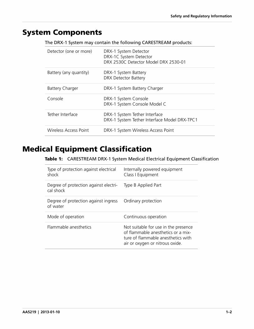
System ComponentsThe DRX-1 System may contain the following CARESTREAM products:
Medical Equipment ClassificationTable 1: CARESTREAM DRX-1 System Medical Electrical Equipment Classification
Detector (one or more) DRX-1 System DetectorDRX-1C System DetectorDRX 2530C Detector Model DRX 2530-01
Battery (any quantity) DRX-1 System BatteryDRX Detector Battery
Battery Charger DRX-1 System Battery Charger
Console DRX-1 System ConsoleDRX-1 System Console Model C
Tether Interface DRX-1 System Tether InterfaceDRX-1 System Tether Interface Model DRX-TPC1
Wireless Access Point DRX-1 System Wireless Access Point
Type of protection against electrical shock
Internally powered equipment Class I Equipment
Degree of protection against electri-cal shock
Type B Applied Part
Degree of protection against ingress of water
Ordinary protection
Mode of operation Continuous operation
Flammable anesthetics Not suitable for use in the presence of flammable anesthetics or a mix-ture of flammable anesthetics with air or oxygen or nitrous oxide.
Safety and Regulatory Information
AA5219 | 2013-01-10 1–3
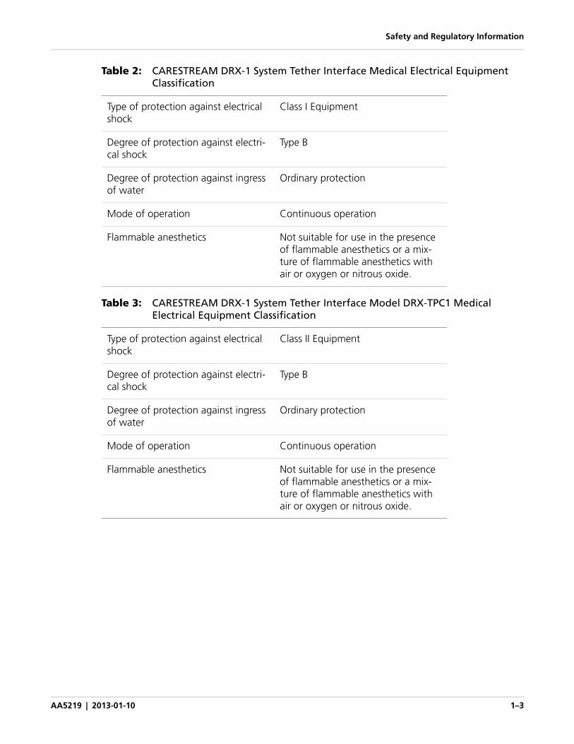
Table 2: CARESTREAM DRX-1 System Tether Interface Medical Electrical Equipment Classification
Table 3: CARESTREAM DRX-1 System Tether Interface Model DRX-TPC1 Medical Electrical Equipment Classification
Type of protection against electrical shock
Class I Equipment
Degree of protection against electri-cal shock
Type B
Degree of protection against ingress of water
Ordinary protection
Mode of operation Continuous operation
Flammable anesthetics Not suitable for use in the presence of flammable anesthetics or a mix-ture of flammable anesthetics with air or oxygen or nitrous oxide.
Type of protection against electrical shock
Class II Equipment
Degree of protection against electri-cal shock
Type B
Degree of protection against ingress of water
Ordinary protection
Mode of operation Continuous operation
Flammable anesthetics Not suitable for use in the presence of flammable anesthetics or a mix-ture of flammable anesthetics with air or oxygen or nitrous oxide.
Safety and Regulatory Information
AA5219 | 2013-01-10 1–4
Safety
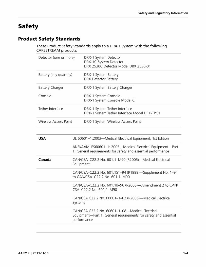
Product Safety Standards These Product Safety Standards apply to a DRX-1 System with the following CARESTREAM products:
Detector (one or more) DRX-1 System DetectorDRX-1C System DetectorDRX 2530C Detector Model DRX 2530-01
Battery (any quantity) DRX-1 System BatteryDRX Detector Battery
Battery Charger DRX-1 System Battery Charger
Console DRX-1 System ConsoleDRX-1 System Console Model C
Tether Interface DRX-1 System Tether InterfaceDRX-1 System Tether Interface Model DRX-TPC1
Wireless Access Point DRX-1 System Wireless Access Point
USA UL 60601–1:2003—Medical Electrical Equipment, 1st Edition
ANSI/AAMI ES60601–1: 2005—Medical Electrical Equipment—Part 1: General requirements for safety and essential performance
Canada CAN/CSA–C22.2 No. 601.1–M90 (R2005)—Medical Electrical Equipment
CAN/CSA–C22.2 No. 601.1S1–94 (R1999)—Supplement No. 1–94 to CAN/CSA–C22.2 No. 601.1–M90
CAN/CSA–C22.2 No. 601.1B–90 (R2006)—Amendment 2 to CAN/CSA–C22.2 No. 601.1–M90
CAN/CSA C22.2 No. 60601–1–02 (R2006)—Medical Electrical Systems
CAN/CSA C22.2 No. 60601–1–08—Medical Electrical Equipment—Part 1: General requirements for safety and essential performance
Safety and Regulatory Information
AA5219 | 2013-01-10 1–5
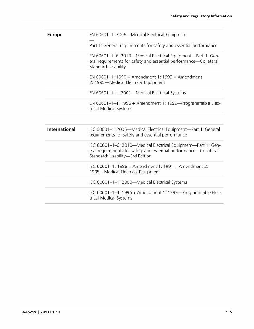
Europe EN 60601–1: 2006—Medical Electrical Equipment—Part 1: General requirements for safety and essential performance
EN 60601–1–6: 2010—Medical Electrical Equipment—Part 1: Gen-eral requirements for safety and essential performance—Collateral Standard: Usability
EN 60601–1: 1990 + Amendment 1: 1993 + Amendment 2: 1995—Medical Electrical Equipment
EN 60601–1–1: 2001—Medical Electrical Systems
EN 60601–1–4: 1996 + Amendment 1: 1999—Programmable Elec-trical Medical Systems
International IEC 60601–1: 2005—Medical Electrical Equipment—Part 1: General requirements for safety and essential performance
IEC 60601–1–6: 2010—Medical Electrical Equipment—Part 1: Gen-eral requirements for safety and essential performance—Collateral Standard: Usability—3rd Edition
IEC 60601–1: 1988 + Amendment 1: 1991 + Amendment 2: 1995—Medical Electrical Equipment
IEC 60601–1–1: 2000—Medical Electrical Systems
IEC 60601–1–4: 1996 + Amendment 1: 1999—Programmable Elec-trical Medical Systems
Safety and Regulatory Information
AA5219 | 2013-01-10 1–6
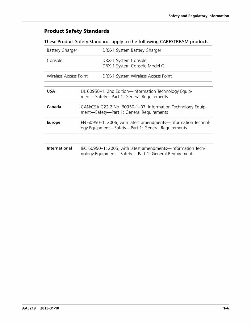
Product Safety Standards
These Product Safety Standards apply to the following CARESTREAM products:
Battery Charger DRX-1 System Battery Charger
Console DRX-1 System ConsoleDRX-1 System Console Model C
Wireless Access Point DRX-1 System Wireless Access Point
USA UL 60950–1, 2nd Edition—Information Technology Equip-ment—Safety—Part 1: General Requirements
Canada CAN/CSA C22.2 No. 60950-1–07, Information Technology Equip-ment—Safety—Part 1: General Requirements
Europe EN 60950–1: 2006, with latest amendments—Information Technol-ogy Equipment—Safety—Part 1: General Requirements
International IEC 60950–1: 2005, with latest amendments—Information Tech-nology Equipment—Safety —Part 1: General Requirements
Safety and Regulatory Information
AA5219 | 2013-01-10 1–7
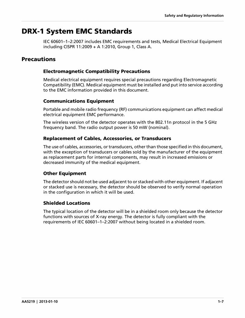
DRX-1 System EMC StandardsIEC 60601–1–2:2007 includes EMC requirements and tests, Medical Electrical Equipment including CISPR 11:2009 + A 1:2010, Group 1, Class A.
Precautions
Electromagnetic Compatibility Precautions
Medical electrical equipment requires special precautions regarding Electromagnetic Compatibility (EMC). Medical equipment must be installed and put into service according to the EMC information provided in this document.
Communications Equipment
Portable and mobile radio frequency (RF) communications equipment can affect medical electrical equipment EMC performance.
The wireless version of the detector operates with the 802.11n protocol in the 5 GHz frequency band. The radio output power is 50 mW (nominal).
Replacement of Cables, Accessories, or Transducers
The use of cables, accessories, or transducers, other than those specified in this document, with the exception of transducers or cables sold by the manufacturer of the equipment as replacement parts for internal components, may result in increased emissions or decreased immunity of the medical equipment.
Other Equipment
The detector should not be used adjacent to or stacked with other equipment. If adjacent or stacked use is necessary, the detector should be observed to verify normal operation in the configuration in which it will be used.
Shielded Locations
The typical location of the detector will be in a shielded room only because the detector functions with sources of X-ray energy. The detector is fully compliant with the requirements of IEC 60601–1–2:2007 without being located in a shielded room.
Safety and Regulatory Information
AA5219 | 2013-01-10 1–8
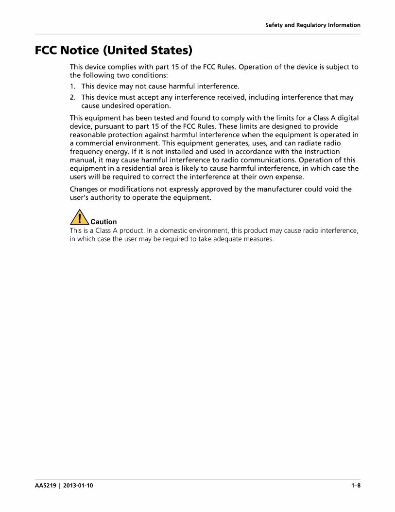
FCC Notice (United States)This device complies with part 15 of the FCC Rules. Operation of the device is subject to the following two conditions:
1. This device may not cause harmful interference.
2. This device must accept any interference received, including interference that may cause undesired operation.
This equipment has been tested and found to comply with the limits for a Class A digital device, pursuant to part 15 of the FCC Rules. These limits are designed to provide reasonable protection against harmful interference when the equipment is operated in a commercial environment. This equipment generates, uses, and can radiate radio frequency energy. If it is not installed and used in accordance with the instruction manual, it may cause harmful interference to radio communications. Operation of this equipment in a residential area is likely to cause harmful interference, in which case the users will be required to correct the interference at their own expense.
Changes or modifications not expressly approved by the manufacturer could void the user’s authority to operate the equipment.
CautionThis is a Class A product. In a domestic environment, this product may cause radio interference, in which case the user may be required to take adequate measures.
Safety and Regulatory Information
AA5219 | 2013-01-10 1–9
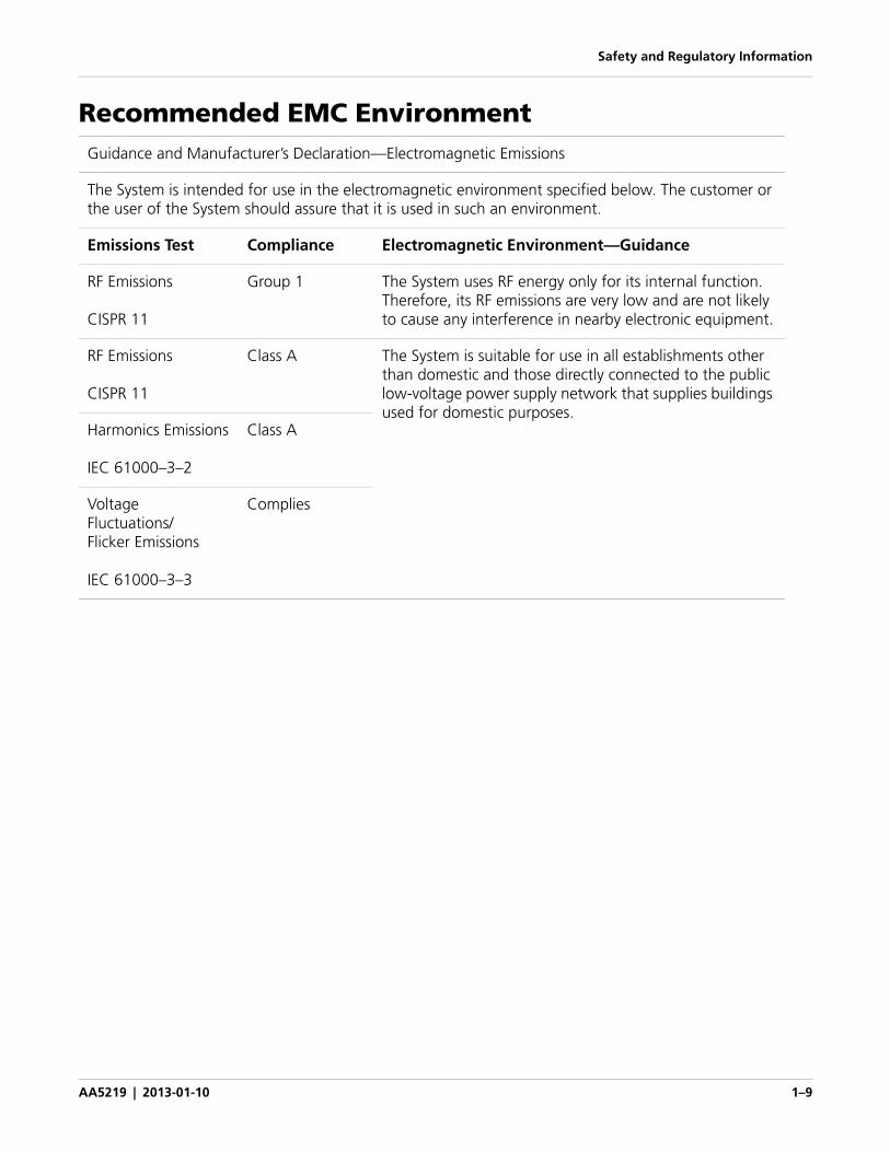
Recommended EMC EnvironmentGuidance and Manufacturer’s Declaration—Electromagnetic Emissions
The System is intended for use in the electromagnetic environment specified below. The customer or the user of the System should assure that it is used in such an environment.
Emissions Test Compliance Electromagnetic Environment—Guidance
RF Emissions
CISPR 11
Group 1 The System uses RF energy only for its internal function. Therefore, its RF emissions are very low and are not likely to cause any interference in nearby electronic equipment.
RF Emissions
CISPR 11
Class A The System is suitable for use in all establishments other than domestic and those directly connected to the public low-voltage power supply network that supplies buildings used for domestic purposes.
Harmonics Emissions
IEC 61000–3–2
Class A
VoltageFluctuations/Flicker Emissions
IEC 61000–3–3
Complies
Safety and Regulatory Information
AA5219 | 2013-01-10 1–10
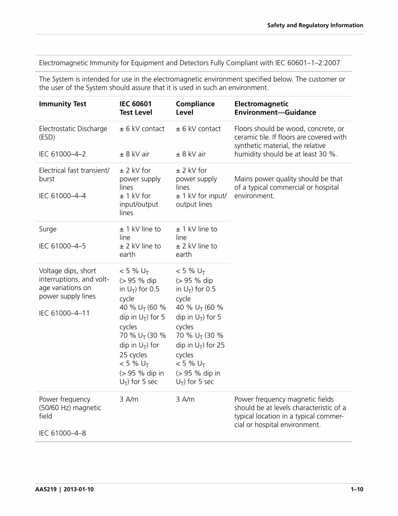
Electromagnetic Immunity for Equipment and Detectors Fully Compliant with IEC 60601–1–2:2007
The System is intended for use in the electromagnetic environment specified below. The customer or the user of the System should assure that it is used in such an environment.
Immunity Test IEC 60601Test Level
ComplianceLevel
Electromagnetic Environment—Guidance
Electrostatic Discharge (ESD)
IEC 61000–4–2
± 6 kV contact
± 8 kV air
± 6 kV contact
± 8 kV air
Floors should be wood, concrete, or ceramic tile. If floors are covered with synthetic material, the relative humidity should be at least 30 %.
Electrical fast transient/burst
IEC 61000–4–4
± 2 kV for power supply lines± 1 kV for input/output lines
± 2 kV for power supply lines± 1 kV for input/output lines
Mains power quality should be that of a typical commercial or hospital environment.
Surge
IEC 61000–4–5
± 1 kV line to line± 2 kV line to earth
± 1 kV line to line± 2 kV line to earth
Voltage dips, short interruptions, and volt-age variations on power supply lines
IEC 61000–4–11
< 5 % UT (> 95 % dip in UT) for 0.5 cycle40 % UT (60 % dip in UT) for 5 cycles70 % UT (30 % dip in UT) for 25 cycles< 5 % UT (> 95 % dip in UT) for 5 sec
< 5 % UT (> 95 % dip in UT) for 0.5 cycle40 % UT (60 % dip in UT) for 5 cycles70 % UT (30 % dip in UT) for 25 cycles< 5 % UT (> 95 % dip in UT) for 5 sec
Power frequency (50/60 Hz) magnetic field
IEC 61000–4–8
3 A/m 3 A/m Power frequency magnetic fields should be at levels characteristic of a typical location in a typical commer-cial or hospital environment.
Safety and Regulatory Information
AA5219 | 2013-01-10 1–11
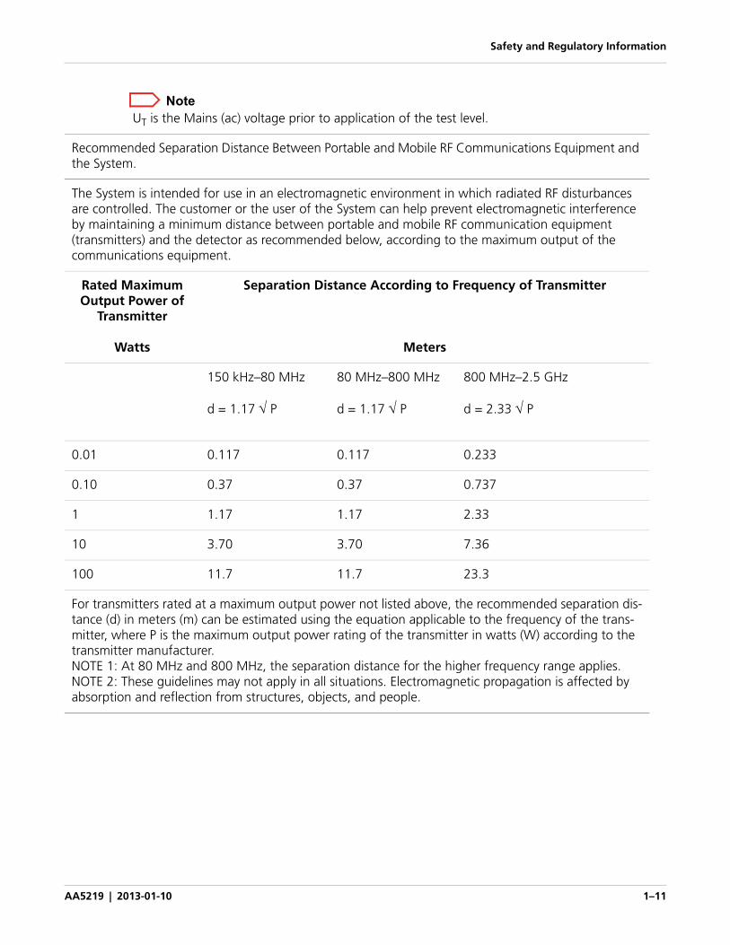
Note UT is the Mains (ac) voltage prior to application of the test level.
Recommended Separation Distance Between Portable and Mobile RF Communications Equipment and the System.
The System is intended for use in an electromagnetic environment in which radiated RF disturbances are controlled. The customer or the user of the System can help prevent electromagnetic interference by maintaining a minimum distance between portable and mobile RF communication equipment (transmitters) and the detector as recommended below, according to the maximum output of the communications equipment.
Rated Maximum Output Power of
Transmitter
Watts
Separation Distance According to Frequency of Transmitter
Meters
150 kHz–80 MHz
d = 1.17 P
80 MHz–800 MHz
d = 1.17 P
800 MHz–2.5 GHz
d = 2.33 P
0.01 0.117 0.117 0.233
0.10 0.37 0.37 0.737
1 1.17 1.17 2.33
10 3.70 3.70 7.36
100 11.7 11.7 23.3
For transmitters rated at a maximum output power not listed above, the recommended separation dis-tance (d) in meters (m) can be estimated using the equation applicable to the frequency of the trans-mitter, where P is the maximum output power rating of the transmitter in watts (W) according to the transmitter manufacturer.NOTE 1: At 80 MHz and 800 MHz, the separation distance for the higher frequency range applies.NOTE 2: These guidelines may not apply in all situations. Electromagnetic propagation is affected by absorption and reflection from structures, objects, and people.
Safety and Regulatory Information
AA5219 | 2013-01-10 1–12
Wireless Declaration
Radio Frequency Exposure Declarations
The System is a portable wireless devices according to FCC regulation 2.1093 (b). The System has been shown to be compliant for localized specific absorption rate (SAR) for uncontrolled environment/general exposure limits specified in ANSI/IEEE standard C95.1–1999. The maximum SAR measurement (averaged over 1 gram of tissue) is 0.992 W/kg. The measured value is well under the spatial peak SAR of 1.6 W/kg specified in FCC regulation 2.1093 d (2) for uncontrolled environment/general exposure conditions.
Under Industry Canada regulations, this radio transmitter may only operate using an antenna of a type and maximum (or lesser) gain approved for the transmitter by Industry Canada.
To reduce potential radio interference to other users, the antenna type and gain should be so chosen that the Equivalent Isotropically Radiated Power (E.I.R.P) is not more than that necessary for successful communication.
Conformément à la réglementation d’Industrie Canada, le présent emétteru radio peut fonctionner avec une antenne d’un type et d’un gain maximal (ou inférieur) approuvé pour l’émetteur par Industrie Canada.
Safety and Regulatory Information
AA5219 | 2013-01-10 1–13
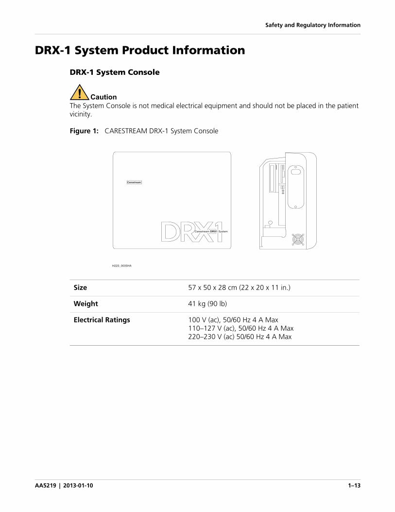
DRX-1 System Product Information
DRX-1 System Console
CautionThe System Console is not medical electrical equipment and should not be placed in the patient vicinity.
Figure 1: CARESTREAM DRX-1 System Console
Size 57 x 50 x 28 cm (22 x 20 x 11 in.)
Weight 41 kg (90 lb)
Electrical Ratings 100 V (ac), 50/60 Hz 4 A Max110–127 V (ac), 50/60 Hz 4 A Max220–230 V (ac) 50/60 Hz 4 A Max
H223_0005HA
Carestream
Carestream SystemDRX1
Safety and Regulatory Information
AA5219 | 2013-01-10 1–14
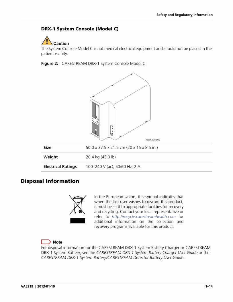
DRX-1 System Console (Model C)
CautionThe System Console Model C is not medical electrical equipment and should not be placed in the patient vicinity.
Figure 2: CARESTREAM DRX-1 System Console Model C
Disposal Information
NoteFor disposal information for the CARESTREAM DRX-1 System Battery Charger or CARESTREAM DRX-1 System Battery, see the CARESTREAM DRX-1 System Battery Charger User Guide or the CARESTREAM DRX-1 System Battery/CARESTREAM Detector Battery User Guide.
Size 50.0 x 37.5 x 21.5 cm (20 x 15 x 8.5 in.)
Weight 20.4 kg (45.0 lb)
Electrical Ratings 100–240 V (ac), 50/60 Hz 2 A
H224_0215AC
In the European Union, this symbol indicates thatwhen the last user wishes to discard this product,it must be sent to appropriate facilities for recoveryand recycling. Contact your local representative orrefer to http://recycle.carestreamhealth.com foradditional information on the collection andrecovery programs available for this product.
Safety and Regulatory Information
AA5219 | 2013-01-10 1–15
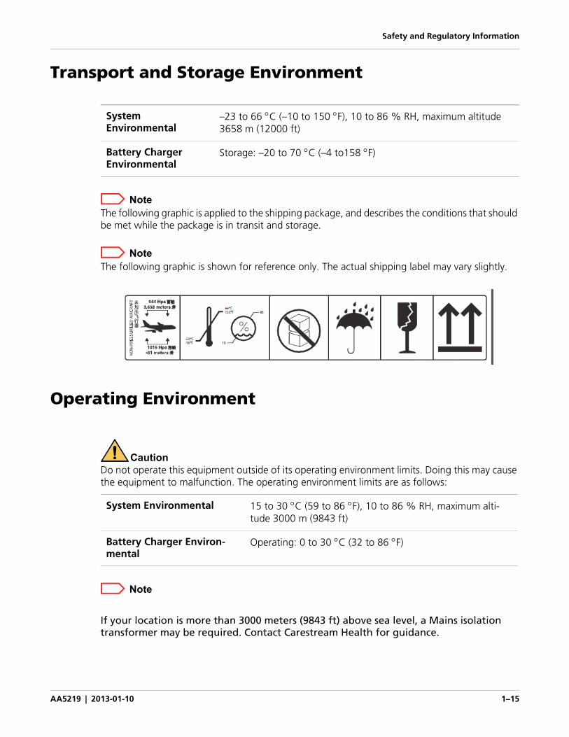
Transport and Storage Environment
NoteThe following graphic is applied to the shipping package, and describes the conditions that should be met while the package is in transit and storage.
NoteThe following graphic is shown for reference only. The actual shipping label may vary slightly.
Operating Environment
CautionDo not operate this equipment outside of its operating environment limits. Doing this may cause the equipment to malfunction. The operating environment limits are as follows:
Note
If your location is more than 3000 meters (9843 ft) above sea level, a Mains isolation transformer may be required. Contact Carestream Health for guidance.
System Environmental
–23 to 66 C (–10 to 150 F), 10 to 86 % RH, maximum altitude 3658 m (12000 ft)
Battery Charger Environmental
Storage: –20to70 C (–4to158 F)
System Environmental 15 to 30 C (59 to 86 F), 10 to 86 % RH, maximum alti-tude 3000 m (9843 ft)
Battery Charger Environ-mental
Operating: 0 to 30 C (32 to 86 F)
Safety and Regulatory Information
AA5219 | 2013-01-10 1–16
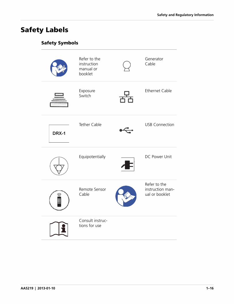
Safety Labels
Safety Symbols
Refer to the instruction manual or booklet
Generator Cable
Exposure Switch
Ethernet Cable
Tether Cable USB Connection
Equipotentially DC Power Unit
Remote Sensor Cable
Refer to the instruction man-ual or booklet
Consult instruc-tions for use
AA5219 | 2013-01-10 2–1
2 Hardware and Operation
Overview
The CARESTREAM DRX-1 System lets you connect a digital DR detector to an analog system and capture images digitally. Use the existing analog console to set up the exam and determine the technique. Then, expose the subject with the System, view the image, and manipulate the image on the computer using Image Viewing Acquisition Software. You can send the image to destinations such as workstations via an Ethernet connection.
The System lets you change a traditional film or Computed Radiography (CR) system to a Digital Radiography (DR) system with minimal changes to hardware. The CARESTREAM DRX-1 System Detector fits existing Buckys, just as cassettes do. A new Console connects to HIS/RIS and PACS. You can continue to use film or CR in your system as desired.
At the Console, the user can download patient data from the RIS (or input from the Console) and initiate prep and expose functions.
The battery-powered detector absorbs, measures, and translates into digital format the X-ray energy absorbed during an X-ray exposure. Software corrects the digital image and generates a preview and full-resolution image on the Console.
The detector operates in a wireless state, using a battery for power, and allowing wireless communication for control and data transmission. The detector may optionally be used with a tether. The tether provides power and communications to the detector.
On the Console, the radiographer:
• Views or prepares the patient data and acquisition procedures for the examination.
• Acquires radiographic images using the detector.
• Sends radiographic images and associated patient data from the detector to an output device, such as hard copy, soft copy, or archive devices.
NoteFor technical information on the safety, regulatory, hardware, and operation of the products not discussed in this manual, see the following publications:
• CARESTREAM DRX-1 System Battery and DRX Detector Battery User Guide
• CARESTREAM DRX-1 System Battery Charger User Guide
• CARESTREAM DRX-1 System Detector/CARESTREAM DRX-1C System Detector/CARESTREAM DRX 2530 Detector Model DRX 2530-01 User Guide
• CARESTREAM DRX-1 System Online Help
Hardware and Operation
AA5219 | 2013-01-10 2–2
Cautions
Caution
• Follow all safety labels on equipment.
• For continued safe use of this equipment, follow the instructions contained in this operator’s manual.
• Study this manual carefully before using the equipment and keep it at hand for quick reference.
• The System must be used only by qualified personnel, and only after training in the specific operations. It is the operator’s responsibility to ensure the patient’s safety while the equipment operates by visual operation, proper patient positioning, and use of the protective devices provided.
• The detector is fragile and contains glass. Handle with care! Dropping or handling the detector roughly could result in damage. If the detector is dropped or handled roughly, or if there is any indication that the image quality is affected, perform a calibration.
• Do not submerge any components of the System in liquid.
• Perform periodic maintenance to ensure continued safe use of the equipment.
• The System must be repaired only by authorized service personnel.
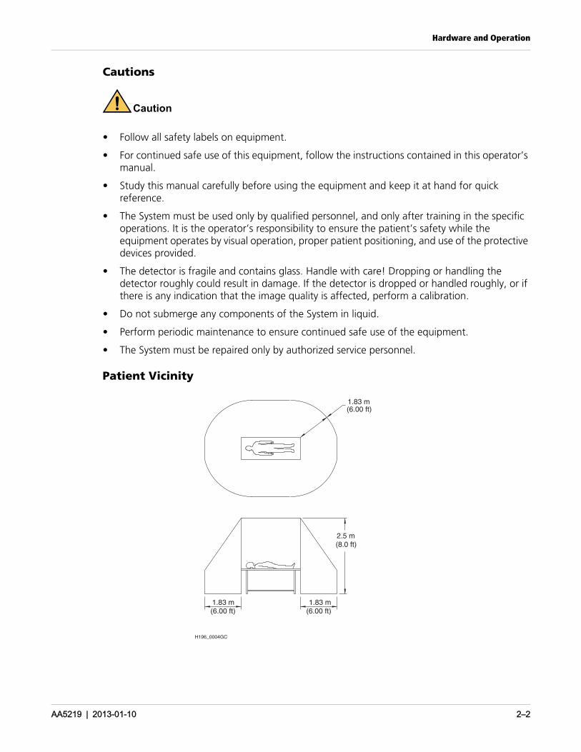
Patient Vicinity
H196_0004GC
1.83 m
2.5 m
1.83 m1.83 m(6.00 ft)(6.00 ft)
(6.00 ft)
(8.0 ft)
Hardware and Operation
AA5219 | 2013-01-10 2–3
CautionThe System Console, Battery Charger, Network Switch, and Wireless Access Point are not medical electrical equipment and should not be placed in the patient vicinity.
CautionKeep all electronic devices (wireless or hard wired) 91cm (3 ft) from the detector when in use.
Installing the HardwareAll equipment installations and adjustments must be performed by personnel authorized by Carestream Health only.
Accessory Information
The use of equipment and/or hardware that does not comply with the equivalent product safety and EMC requirements of this product may lead to a reduced level of safety and/or EMC performance of the resulting system.
Consideration relating to the choice of accessory equipment used with this product shall include:
• Use of the accessory in the patient’s vicinity.
• Evidence that the safety certification of the accessory has been performed in accordance with applicable coordinated harmonized product safety standards per IEC 60601–1–1.
• Evidence that applicable emission certification of the accessory has been performed.
Battery Information
A battery is required for wireless or tethered use. For complete information about the batteries used with the DRX detectors, see the CARESTREAM DRX-1 System Battery and DRX Detector Battery User Guide or the Quick Reference Card for the CARESTREAM DRX-1 System and the DRX-Mobile Retrofit Kit.
Installing the BatteryUse only Carestream batteries in DRX detectors.
1. Place a fully charged battery in the battery footprint in the detector so that the contacts on the back edge of the battery are inserted first. The battery fits into the detector only one way.
2. Push the battery down firmly until the latch catches.
Hardware and Operation
AA5219 | 2013-01-10 2–4
Removing a Single-Point Latch BatteryA battery may have a single-point latch or a two-point latch.
Prerequisites:
A DRX battery that has a single-point latch.
1. Place the detector on a flat surface outside of the patient vicinity.
2. Place a tool such as the tip of a ballpoint pen in the release slot, and push down on the latch.
The battery releases for easy removal.
Removing a Two-Point Latch Battery
Prerequisites:
A DRX battery that has a two-point latch, such as the DRX Detector Battery.
1. Place the detector on a flat surface outside of the patient vicinity.
2. With one hand, press and hold the round button to release the latch.
3. With the other hand, pull the tab away from the battery.
Do these steps simultaneously so that the battery releases for easy removal.
Turning the System On1. Press the On switch on the Console. For systems that have a UPS, press the On switch
on the UPS.
2. Press the On switch on the computer and monitor.
3. When the software initializes, the system is ready for use.
4. Insert a fully charged battery into the detector.
Turning the System Off1. Select the Quick Menu in the lower left corner of the screen.
2. Select Shut Down.
3. Turn Off the monitor.
4. For systems with a UPS, turn Off the UPS.
5. Turn Off the Console.
Hardware and Operation
AA5219 | 2013-01-10 2–5
The DRX-1 System Console may be completely powered up or powered down via the switch located adjacent to the Mains cord connector. Alternatively, to power down, the Mains cord may be disconnected at the cord connector.
Caution
To avoid the risk of electric shock, this equipment must only be connected to a supply mains with protective earth.
Caution
This device must be positioned where the operator has easy access to the appliance coupler (cord disconnect device).
Caution
The customer is responsible for ensuring that Ethernet interface to their network conforms to isolation requirements of IEC60601:1: 2005.
Turning the DRX-1 System Console and the DRX-1 System Console Model C On and Off
The Console may be completely powered up or powered down via the switch located adjacent to the Mains cord connector. Alternatively, to power down, the Mains cord may be disconnected at the cord connector.
Hardware and Operation
AA5219 | 2013-01-10 2–6
Tether Operation
Tether InterfacesThere are two system tether interfaces: the CARESTREAM DRX-1 System Tether Interface and the CARESTREAM DRX-1 Tether Interface Model DRX-TPC1.
DRX-1 System Tether Interface
CautionDo not allow the detector to come in direct contact with a patient while the detector is connected to a tether with the DRX-1 System Tether Interface. This interface must be located outside of the patient vicinity.
Turning the DRX-1 System Tether Interface On and Off
The DRX-1 System Tether Interface may be powered up or powered down via the switch located adjacent to the Mains cord connector. Alternatively, to power down, the Mains cord may be disconnected at the cord connector.
DRX-1 System Tether Interface Model DRX-TPC1
The DRX-TPC1 Tether Interface may be used with a tether in the patient vicinity. The tether is identified by a blue wrapping on the tether cable.
The plastic DRX-TPC1 Tether Interface box is identified with a square Class II mark on the CARESTREAM DRX-1 System Tether Interface Data Plate:
CARESTREAM System Tether Interface Specifications
Size 16 x 30 x 7 cm (6 x 12 x 3 in.)
Weight 2.3 kg (5.0 lb)
Electrical Ratings 100–240 V (ac), 0.75 A50/60 Hz
Hardware and Operation
AA5219 | 2013-01-10 2–7
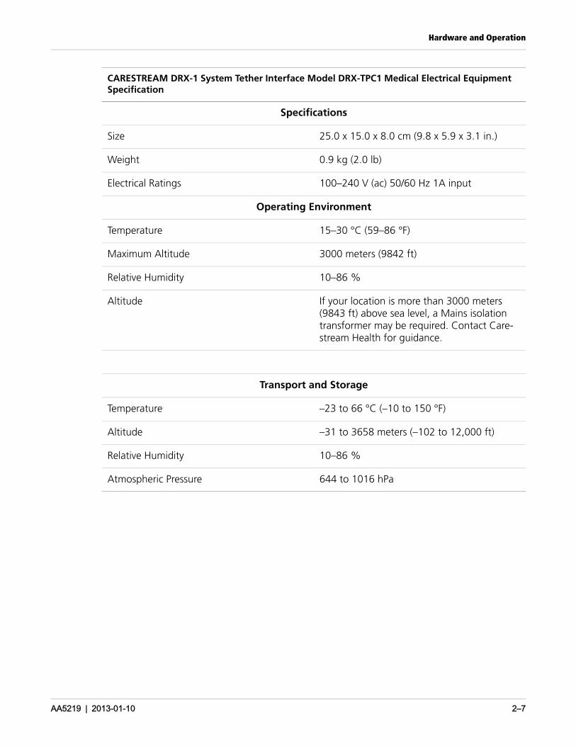
CARESTREAM DRX-1 System Tether Interface Model DRX-TPC1 Medical Electrical Equipment Specification
Specifications
Size 25.0 x 15.0 x 8.0 cm (9.8 x 5.9 x 3.1 in.)
Weight 0.9 kg (2.0 lb)
Electrical Ratings 100–240 V (ac) 50/60 Hz 1A input
Operating Environment
Temperature 15–30 °C (59–86 °F)
Maximum Altitude 3000 meters (9842 ft)
Relative Humidity 10–86 %
Altitude If your location is more than 3000 meters (9843 ft) above sea level, a Mains isolation transformer may be required. Contact Care-stream Health for guidance.
Transport and Storage
Temperature –23 to 66 °C (–10 to 150 °F)
Altitude –31 to 3658 meters (–102 to 12,000 ft)
Relative Humidity 10–86 %
Atmospheric Pressure 644 to 1016 hPa
Hardware and Operation
AA5219 | 2013-01-10 2–8
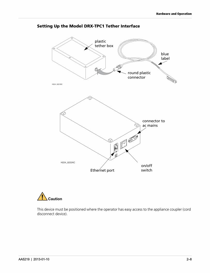
Setting Up the Model DRX-TPC1 Tether Interface
Caution
This device must be positioned where the operator has easy access to the appliance coupler (cord disconnect device).
H224_0221BC
plastictether box
round plasticconnector
bluelabel
Ethernet
H224_0222AC
Ethernet porton/offswitch
connector toac mains
Hardware and Operation
AA5219 | 2013-01-10 2–9
Cleaning
Cleaning the Hardware
Our instructions serve as a guideline for best practices. The cleaners listed in our instructions ensure that the paint finish does not fade or cause harm to the rubber screw covers, etc. We are also aware that each facility will have its own requirements, guidelines and approved cleaners. If your facility has such requirements, use what is mandated as long as it does not cause harm to the surfaces being cleaned. Carestream will not be responsible for replacement of parts that are shown to be damaged by improper cleaning agents
CautionDo not operate the equipment when cleaning the equipment.
CautionDo not spray cleaning solution directly onto the equipment. Moisten a cloth with a 70 % isopropyl alcohol solution and apply to patient contact areas after each contact.
CautionIsopropyl alcohol is a flammable solvent. Read and follow instructions in the Material Safety Data Sheet (MSDS).
CautionDo not immerse the equipment in liquid.
Hardware and Operation
AA5219 | 2013-01-10 2–10
System Maintenance
CautionDo not attempt mechanical or electrical repair of the System. Contact authorized service personnel if any unit does not perform to your satisfaction.
The System must be maintained in good operating order at all times to provide safe conditions for operating personnel and patients. The System must also be maintained to prevent possible loss of patient or image data.
Maintenance Schedule
CautionThe System must be repaired only by authorized service personnel.
Daily:
• Clean the equipment.
• Check the equipment integrity (see below).
• Perform Daily Refresh Calibration if required. See “Running Detector Calibrations” in the .DRX-1 System Online Help
Biannually
• Perform an X-ray Calibration. See “Running Detector Calibrations” in the CARESTREAM DRX-1 System Online Help.
Periodically, or as needed:
• Recalibrate the touchscreen on the Console as needed. Recalibration instructions are included in the CARESTREAM DRX-1 System Online Help.
• Report any unusual conditions to your authorized service representative.
Check the Equipment Integrity
To make sure that the equipment is functioning and operating safely, check that:
• The fastening hardware connects tightly.
• All name plates, legal labels, and warning labels are legible and secure.
• No cables have abrasions or damage, particularly in locations where cables are draped and subject to stress.
Grid Recommendation
Artifacts are not visible when the 103 line pair/inch low frequency stationary grid is used.
Hardware and Operation
AA5219 | 2013-01-10 2–11
Protective Enclosures
CautionWhen there is a risk of fluids contacting the detector, place the detector in a protective bag. If you are using a protective enclosure around the detector, remove the enclosure immediately after use to prevent the detector from overheating.
Power Failures
There are various types of power disruptions that can affect a system: voltage sags, voltage surges, brownouts, line noise, high voltage spikes, frequency variations, switching transients, and harmonic distortions. These disruptions can be minimized by an Uninterruptible Power Supply (UPS). The DRX-1 System Console Model C does not include a UPS.
NoteA UPS provides back-up power in the event of a power failure. A UPS also conditions the power provided to the System. Back-up power will last for a specific length of time, dependent on the UPS energy storage capacity and the power requirements of the equipment. If you choose to provide a UPS for your System, follow the manufacturer’s recommendation for use and battery replacement.
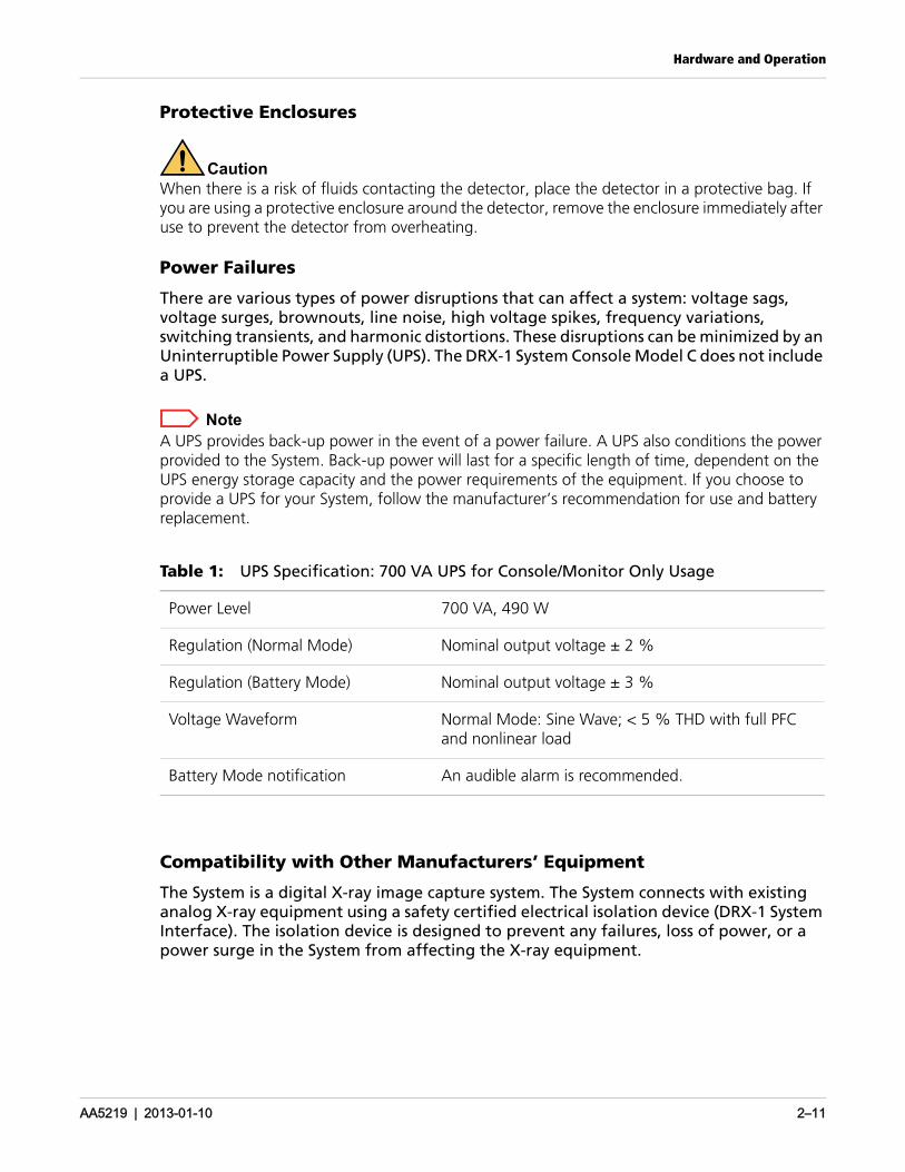
Table 1: UPS Specification: 700 VA UPS for Console/Monitor Only Usage
Compatibility with Other Manufacturers’ Equipment
The System is a digital X-ray image capture system. The System connects with existing analog X-ray equipment using a safety certified electrical isolation device (DRX-1 System Interface). The isolation device is designed to prevent any failures, loss of power, or a power surge in the System from affecting the X-ray equipment.
Power Level 700 VA, 490 W
Regulation (Normal Mode) Nominal output voltage ± 2 %
Regulation (Battery Mode) Nominal output voltage ± 3 %
Voltage Waveform Normal Mode: Sine Wave; < 5 % THD with full PFC and nonlinear load
Battery Mode notification An audible alarm is recommended.
Hardware and Operation
AA5219 | 2013-01-10 2–12
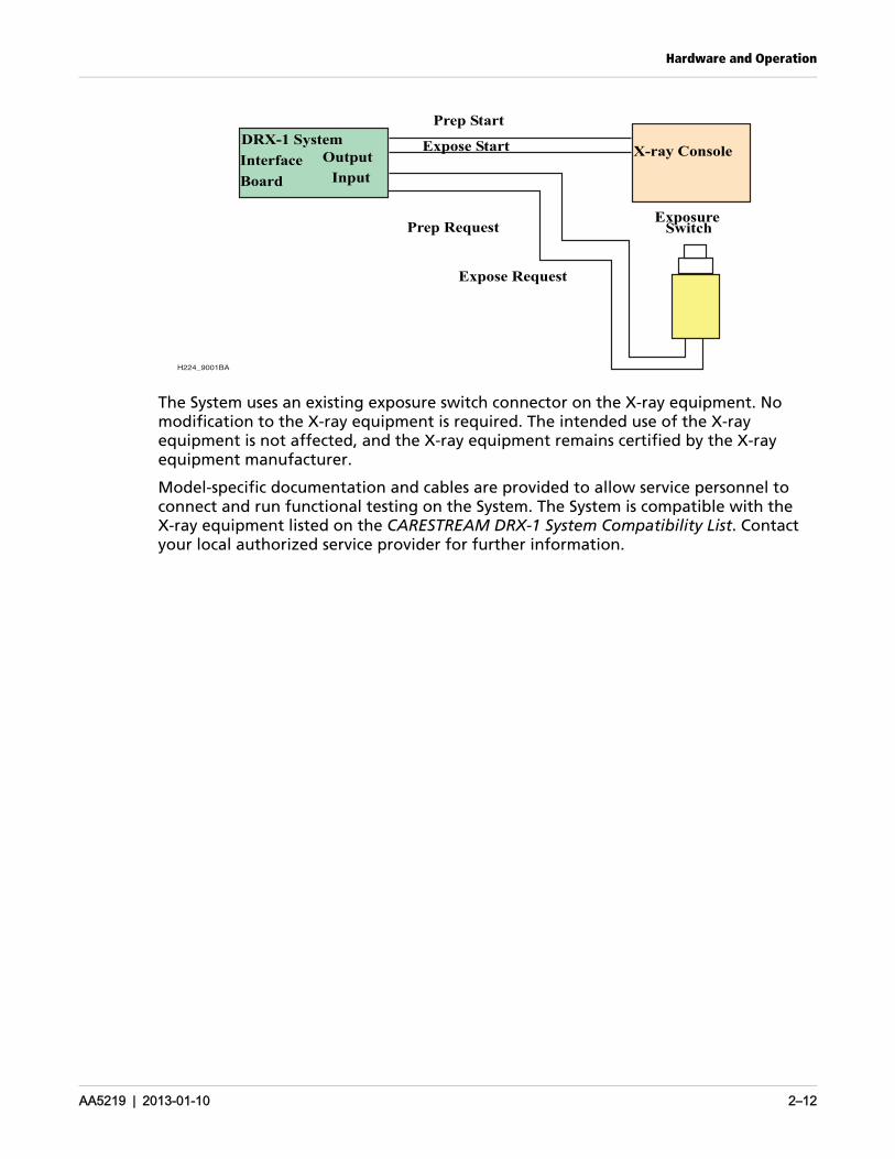
The System uses an existing exposure switch connector on the X-ray equipment. No modification to the X-ray equipment is required. The intended use of the X-ray equipment is not affected, and the X-ray equipment remains certified by the X-ray equipment manufacturer.
Model-specific documentation and cables are provided to allow service personnel to connect and run functional testing on the System. The System is compatible with the X-ray equipment listed on the CARESTREAM DRX-1 System Compatibility List. Contact your local authorized service provider for further information.
H224_9001BA
Prep Start
Expose Request
X-ray Console
Input
ExposureSwitch
Expose Start
Board
Interface
DRX-1 System
Prep Request
Output
Hardware and Operation
AA5219 | 2013-01-10 2–13
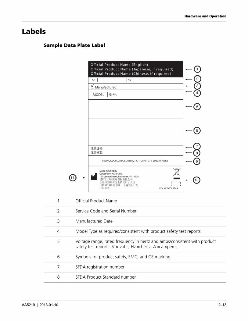
Labels
Sample Data Plate Label
1 Official Product Name
2 Service Code and Serial Number
3 Manufactured Date
4 Model Type as required/consistent with product safety test reports
5 Voltage range, rated frequency in hertz and amps/consistent with product safety test reports: V = volts, Hz = hertz, A = amperes
6 Symbols for product safety, EMC, and CE marking
7 SFDA registration number
8 SFDA Product Standard number
Made in China by Carestream Health, Inc.150 Verona Street, Rochester, NY 14608
1510
SNSC
MODEL
Manufactured:
P/N XXXXXX REV A
Official Product Name (Engl ish)Official Product Name (Japanese, i f required)Official Product Name (Chinese, i f required)
THIS PRODUCT COMPLIES WITH 21 CFR CHAPTER 1, SUBCHAPTER J
10
9
8
7
6
5
4
3
2
1
11

Hardware and Operation
AA5219 | 2013-01-10 2–14
9 Compliance statement according to FDA requirements for laser products
10 Label manufacturer registration number and material specification
11 Made in statement

Hardware and Operation
AA5219 | 2013-01-10 2–15
Publication HistoryRevision Date Change
A 2013-01-10 Initial release
Carestream Health, Inc. 150 Verona Street Rochester, NY 14608 United States
© Carestream Health, Inc., 2013
Printed in the United States
CARESTREAM and DRX-1 are trademarks of Carestream Health.
Pub No. AA5219Rev A
Recommended