w w w . e l e c t r o n i c o n . c o m
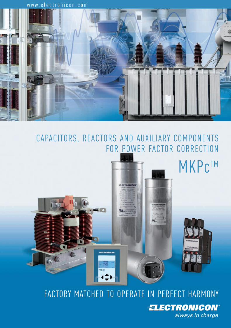
CAPACITORS, REACTORS AND AUXILIARY COMPONENTS FOR POWER FACTOR CORRECTION
MKPcTM
FACTORY MATCHED TO OPERATE IN PERFECT HARMONY
CONTENTS
INTRODUCTION 1
CAPACITORS AND REACTORS
General technical data . . . . . . . . . . . . . . . . . . . . . . . . . . . . . . . . . . . . . . . . . . . . . . . . . . . . . . . . . . . . . . . 3
Dimension drawings . . . . . . . . . . . . . . . . . . . . . . . . . . . . . . . . . . . . . . . . . . . . . . . . . . . . . . . . . . . . . . . . . . . 4
How to read the selection charts . . . . . . . . . . . . . . . . . . . . . . . . . . . . . . . . . . . . . . . . . . . . . . . 5
MKPc™ 400…440V 50Hz . . . . . . . . . . . . . . . . . . . . . . . . . . . . . . . . . . . . . . . . . . . . . . . . . . . . . . . . . . . . . 6
FK-Dr™ 400V 50Hz 7% . . . . . . . . . . . . . . . . . . . . . . . . . . . . . . . . . . . . . . . . . . . . . . . . . . . . . . . . . . . . . . . 7
FK-Dr™ 400V 50Hz 7% . . . . . . . . . . . . . . . . . . . . . . . . . . . . . . . . . . . . . . . . . . . . . . . . . . . . . . . . . . . . . . . 8
FK-Dr™ 400V 50Hz 5.67% . . . . . . . . . . . . . . . . . . . . . . . . . . . . . . . . . . . . . . . . . . . . . . . . . . . . . . . . . . 9
FK-Dr™ 400V 50Hz 5.67% . . . . . . . . . . . . . . . . . . . . . . . . . . . . . . . . . . . . . . . . . . . . . . . . . . . . . . . . . . 10
MKPc™ 480…525V 50Hz . . . . . . . . . . . . . . . . . . . . . . . . . . . . . . . . . . . . . . . . . . . . . . . . . . . . . . . . . . . . . 11
CAPACITOR CONTACTORS . . . . . . . . . . . . . . . . . . . . . . . . . . . . . . . . . . . . . . . . . . . . . . . . . . . . . . . . 12
POWER FACTOR CONTROLLERS . . . . . . . . . . . . . . . . . . . . . . . . . . . . . . . . . . . . . . . . . . . . . 13
IMPORTANT REMARKS . . . . . . . . . . . . . . . . . . . . . . . . . . . . . . . . . . . . . . . . . . . . . . . . . . . . . . . . . . . . . . 14
APPROVAL CERTIFICATES . . . . . . . . . . . . . . . . . . . . . . . . . . . . . . . . . . . . . . . . . . . . . . . . . . . . . . . . 15
PACKING DETAILS . . . . . . . . . . . . . . . . . . . . . . . . . . . . . . . . . . . . . . . . . . . . . . . . . . . . . . . . . . . . . . . . . . . . . . . 16
CONTENTS
The construction of reliable equipment for power factor correction requires not only your excellent experience, but also top-class compo-
nents. No compromise in quality and safety should be permitted when it comes to the key parts of your PFC equipment. Because we do
care, we are offering you the full set of essential components for your capacitor bank:� The heart: Capacitors. Without them, PFC is impossible. They are the most sensitive and most important component.� The protection: Most PFC nowadays cannot do without detuning reactors for harmonic protection anymore.� The brain: The controller shall know what to do, and when.� The muscle: Switching is one of the key functions in your PFC, and switching capacitors means maximum stress.
1
WE KNOW
WHAT WORKS BEST
FACTORY MATCHED TO WORK IN PERFECT HARMONY. ALL KEY COMPONENTS FROM ONE SOURCE.
FIRST CLASS POWER
CAPACITORS FOR YOUR PFCMKPc™ COMPACT RANGE
Apart from your excellent experience, the construction of reliable
and competitive equipment for power factor correction requires top-
class components at reasonable cost. No compromise in quality and
safety should be permitted when it comes to the key part of your
PFC equipment.
Germany’s largest manufacturer of power capacitors manufactures
all components with highest care and expertise and is your best
choice for power capacitors and detuning reactors.
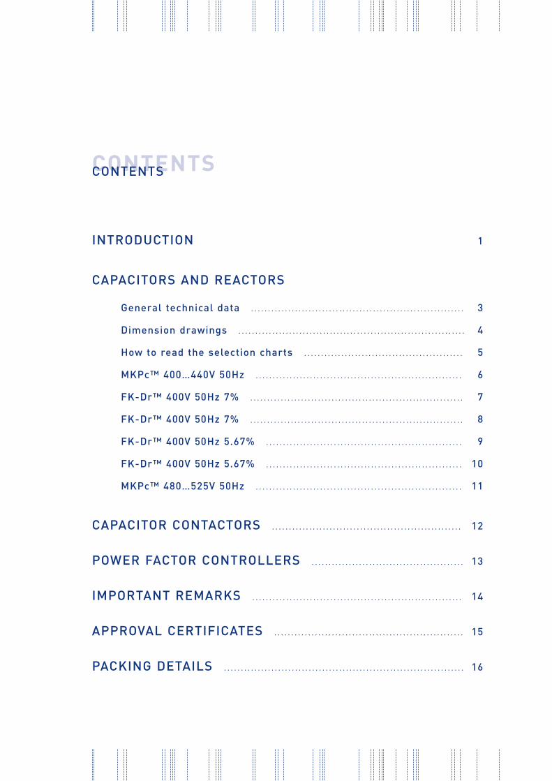
Being f illed with the same neutral, inert gas as the capacitors of
our renowned MKPg™ range, the phase shifters of our low-cost MKPc™-
series are environmentally fr iendly, ver y compact, and easy to
handle. Our capacitors may be mounted in any desired position. Should
leakage occur, the leaking gas would escape into the atmosphere
causing no undesirable effects to the adjacent equipment, e.g.
damage, pollution, or staining. When disposing of the capacitors,
no liquids or toxic gasses need to be considered.
Three-phase MKPc™ capacitors contain three separate capacitor
elements connected in delta. By using the market's best low-loss,
self-healing polypropylene f ilms and sophisticated manufacturing
techniques such as high-vacuum drying and special coating pat-
terns, MKPc™ provide long service life with constant capacitance
and high switching stability. As a matter of course, all our power capa-
citors are provided with BAM™ (overpressure break-action mechanism)
as standard, for safe mode of failure.
Our original CAPAGRIP™ terminals with their options K and L
guarantee optimum sealing of the capacitors, and offer convenient
connection of cables up to 25mm². A special spring system gua-
rantees reliable and durable operation of the clamp. They are rated
IP20, i.e. protected against accidental finger contact with live parts.
CAPAGRIP™ K includes bleeding resistors for a discharge below
50V within less than 60 seconds; CAPAGRIP™ L permits the
direct connection of discharge reactors and discharge resistor
modules, as well as convenient parallel connection of additional
capacitors within the permitted current limits.
For more detailed information, instructions on mounting and proper calculation, please consult our comprehensive catalogue “Capacitors and Reactors for PowerFactor Correction” or check www.electronicon.com
SHIELD YOUR CAPACITORS
FROM RESONANCESFK-Dr™ THREE PHASE DETUNING REACTORS
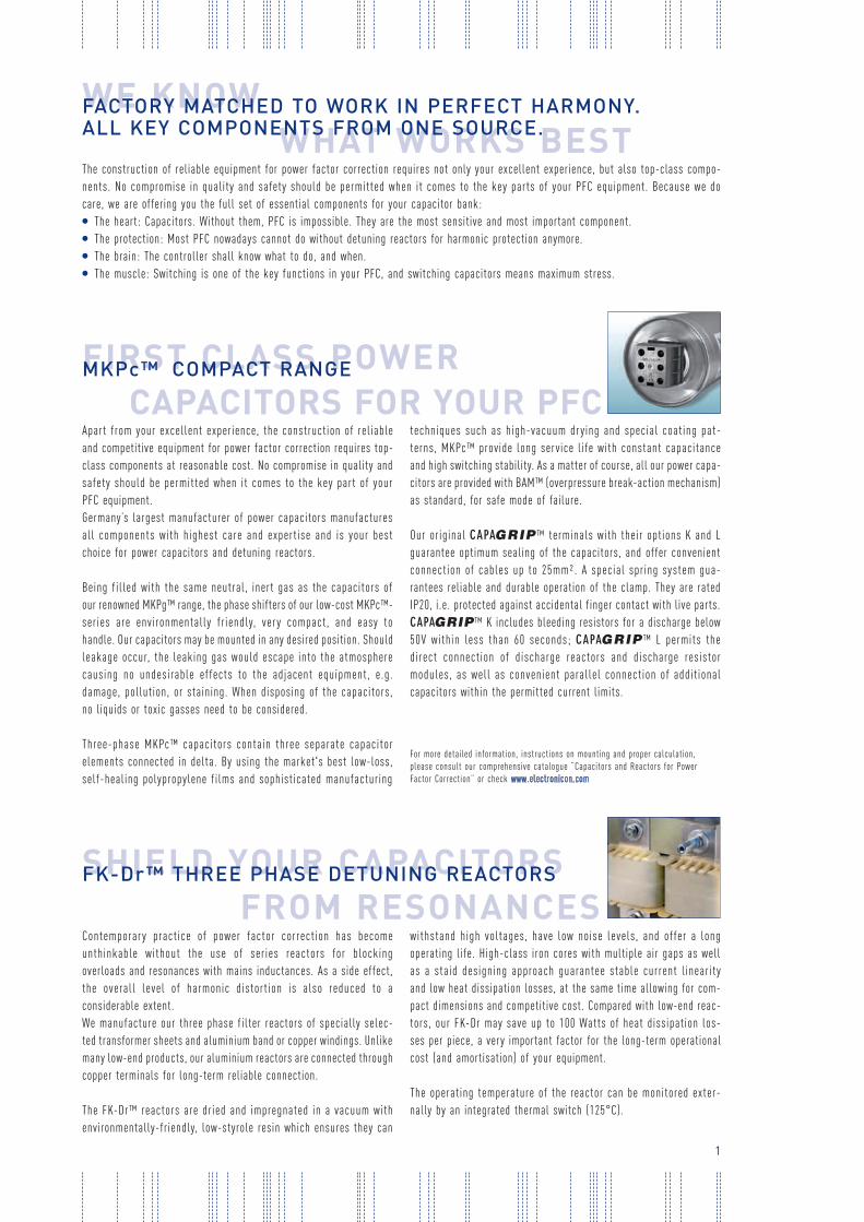
Contemporary practice of power factor correction has become
unthinkable without the use of series reactors for blocking
overloads and resonances with mains inductances. As a side effect,
the overall level of harmonic distortion is also reduced to a
considerable extent.
We manufacture our three phase f ilter reactors of specially selec-
ted transformer sheets and aluminium band or copper windings. Unlike
many low-end products, our aluminium reactors are connected through
copper terminals for long-term reliable connection.
The FK-Dr™ reactors are dried and impregnated in a vacuum with
environmentally-friendly, low-styrole resin which ensures they can
withstand high voltages, have low noise levels, and offer a long
operating life. High-class iron cores with multiple air gaps as well
as a staid designing approach guarantee stable current l inearity
and low heat dissipation losses, at the same time allowing for com-
pact dimensions and competitive cost. Compared with low-end reac-
tors, our FK-Dr may save up to 100 Watts of heat dissipation los-
ses per piece, a very important factor for the long-term operational
cost (and amortisation) of your equipment.
The operating temperature of the reactor can be monitored exter-
nally by an integrated thermal switch (125°C).
2
Along with the common standard-rated reactors (for the usual range
of capacitors) we offer a range of special reactors which, combi-
ned with properly-rated capacitors, produce exactly the required
kvar output at mains voltage, allowing for reduced size and cost of
your installation.
The kvar output of a capacitor depends on the voltage it is charged
with. At higher voltage, equal capacitance delivers more kvar.
A “non-adjusted reactor” (D) is matched to a power capacitor with
standard rating at system voltage. This allows for use of capacitors
“off the shelf”, however with the increased output of kvar due to
voltage rise inside the LC circuit, more power output is installed
than actually required by the customer.
A reactor with adjusted rating (Dla) is considering this internal
voltage rise inside the series circuit of capacitor/reactor, and is
matched to a specially dimensioned capacitor with reduced
capacitance. Advantage: The exact power is installed as required
by the customer, and switching devices are stressed less. Both
capacitor and reactor are smaller than the non-adjusted solution.
Note that exact sizing of the capacitor is necessary.
For more detailed information, please order our comprehensive catalogue “Capacitors and Reactors for Power Factor Correction”.
The PFR-X power factor controller calculates the active and reac-
tive power in the mains from the measured current and voltage. The
intelligent control algorithm optimizes the switching sequences and
guarantees for short regulation times with minimum number of swit-
chings. At the same time, switching operations are equally shared
among the available capacitor branches where possible. The inte-
grated connection control immediately detects in which phases
voltage and current are measured, and adapts the entire system
automatically. The very low current threshold of 10mA allows for
very reliable and exact PF control. 1A as well as 5A current trans-
formers can be used without additional manual adjustments. The power
supply covers a voltage range of 90...550V.
The rated mains voltage is the only value to be entered before
commencing operation of the PFR-X. Without this entr y, the
controller blocks operation to protect the capacitors. All other
relevant parameters have been preset by the manufacturer for imme-
diate start of operation in nearly any common configuration. Individual
adjustment and optimization of the control parameters is possible
at any time, even during operation of the equipment.
The controller will operate correctly even if the value of the
current transformer ratio has not been entered. It monitors the
temperature inside the capacitor cabinet by means of an integrated
sensor.
For more detailed information, please order our comprehensive catalogue “Capacitors and Reactors for Power Factor Correction”.
GOOD CAPACITORS
ALONE WON’T DOPFR-X POWER FACTOR CONTROLLER
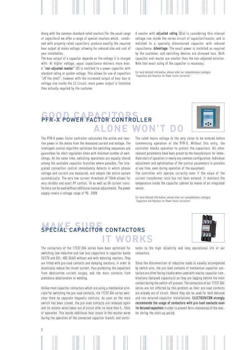
The contactors of the 17237.004 series have been optimized for
switching low-inductive and low loss capacitors in capacitor banks
(IEC70 and 831, VDE 0560) without and with detuning reactors. They
are fitted with pre-load contacts and damping resistors, in order to
drastically reduce the inrush current, thus protecting the capacitors
from destructive current surges, and the main contacts from
premature deterioration or welding.
Unlike most capacitor contactors which are using a mechanical prin-
ciple for switching the pre-load contacts, the 17237.004 series swit-
ches them by separate magnetic controls. As soon as the main
switch has been closed, the pre-load contacts are released again
and its resistor wires taken out of circuit after no more than 5…10ms
of operation. This avoids additional heat losses in the resistor wires
during the operation of the connected capacitor branch, and contri-
butes to the high reliabil ity and long operational l ife of our
contactors.
Since the disconnection of inductive loads is usually accompanied
by switch arcs, the pre-load contacts of mechanical capacitor con-
tactors are often facing trouble when used with reactor-capacitor com-
binations (detuned capacitors) as they are lagging behind the main
contact during the switch-off process. The contactors of our 17237.004
series are not affected by this problem as their pre-load contacts
are already out of circuit. Hence they can be used for both detuned
and non-detuned capacitor installations. ELECTRONICON strongly
recommends the usage of contactors with pre-load contacts even
for detuned capacitors in order to prevent ferro-resonances of the reac-
tor during the start-up period.
MAKE SURE
IT WORKSSPECIAL CAPACITOR CONTACTORS

3
design pressed aluminium can with stud M12 × 16, aluminium lid
internal connection delta
tolerance of capacitance – 5 ... + 10%
terminals three phase terminal, M4 screws (Torx T20)
safety device BAMTM (overpressure break action mechanism)
dielectric material low-loss polypropylene, dry
impregnant (f illing material) N2
mounting position any position
permitted overvoltages and test voltages see data charts for details
maximum permissible current at least 1.3 IN, see data charts for details
max. inrush current 300 × IN
dissipation losses approx.. 0.25 … 0.40W/kvar
max. relative humidity 95%
max. altitude 4000m a.s.l.
ambient temperature class – 40°/D (max. 55°C, average 24h: 45°C)
statistical life expectancy (permitted failure rate ≤ 3 %) > 100 000 h
standards IEC 60831 (2003), VDE 0560-46/47
UL Standard No. 810, CSA C22.2 No. 190-M1985,
GOST 1282-88, ISI 13340/13341
approval marks
MKPc™
CAPACITORS AND REACTORS – GENERAL TECHNICAL DATA
design three phase, iron core with multiple air gaps, IP00
tolerance of inductance – 3 ... + 3%
terminals copper lugs; cables available on request
winding material aluminium band or copper winding
safety device thermal switch (125°C ± 5K)
impregnant polyester resin Class F
current linearity 7%: 1.5 × IN, higher values on request
5.67%: 1.8 × IN, higher values on request
permitted harmonic load U3 = 0.5% UN
U5 = 6.0% UN
U7 = 5.0% UN
U11 = 3.5% UN
U13 = 3.0% UN
insulation voltage winding to core 3kV
max. relative humidity 95%
temperature class T40
statistical life expectancy ( permitted failure rate ≤ 3% ) > 200 000 h
standards EN61558-2-20:2000, VDE 0570-2
approval marks
FK-Dr™

4
DIMENSION DRAWINGS
15 ... 20mm
CAPAGRIP™ K CAPAGRIP™ L
terminal design CAPAGRIP™ K CAPAGRIP™ L
max.cable ∅ 1 × 10mm²/contact 2 × 25mm²/contact
max.current /ph 39A 56A
fastening torque 1.2 … 2.0Nm 2.5 ... 3.0Nm
discharge resistors included separate module
Detuning reactors
Design shown as listed in this catalogue.Optional terminations:
screw terminal blocktemperature-proof flexible cables
Alternative mounting option:threaded bolts for lateral mounting
power terminal
Temperature switch
DISCHARGE DISCHARGE MODULES - THE CONVENIENT MATCH
Capacitors of the CAPAGRIP™ K series are fitted with discharge resistors for a discharge < 50V within < 60 seconds.
For CAPAGRIP™ L, we provide separate resistor modules in a finger-proof housing (IP20) for fast and convenient
connection to the terminal.
resistance Umax L order no.(kΩ) (V) (mm)
3 × 120 480 V 27 275.100-10120
3 × 180 600 V 27 275.100-10180
5
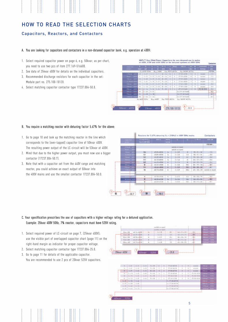
HOW TO READ THE SELECTION CHARTS
Capacitors, Reactors, and Contactors
A. You are looking for capacitors and contactors in a non-detuned capacitor bank, e.g. operation at 400V:
1. Select required capacitor power on page 6, e.g. 50kvar; as per chart,
you need to use two pcs of item 277.169-516600.
2. See data of 25kvar 400V for details on the individual capacitors.
3. Recommended discharge resistors for each capacitor in the set:
Module part no. 275.100-10120.
4. Select matching capacitor contactor type 17237.004-50.0.
B. You require a matching reactor with detuning factor 5.67% for the above:
1. Go to page 10 and look up the matching reactor in the line which
corresponds to the (over-lapped) capacitor line of 50kvar 400V.
The resulting power output of the LC-circuit will be 53kvar at 400V.
2. Mind that due to the higher power output, you must now use a bigger
contactor (17237.004-50.7).
3. Note that with a capacitor set from the 440V range and matching
reactor, you could achieve an exact output of 50kvar into
the 400V mains and use the smaller contactor 17237.004-50.0.
C. Your specification prescribes the use of capacitors with a higher voltage rating for a detuned application.
Example: 25kvar 400V 50Hz, 7% reactor, capacitors must have 525V rating.
1. Select required power of LC-circuit on page 7, (25kvar 400V);
use the visible part of overlapped capacitor chart (page 11) on the
right-hand margin as indicator for proper capacitor voltage.
2. Select matching capacitor contactor type 17237.004-25.0.
3. Go to page 11 for details of the applicable capacitor.
You are recommended to use 2 pcs of 20kvar 525V capacitors.
6
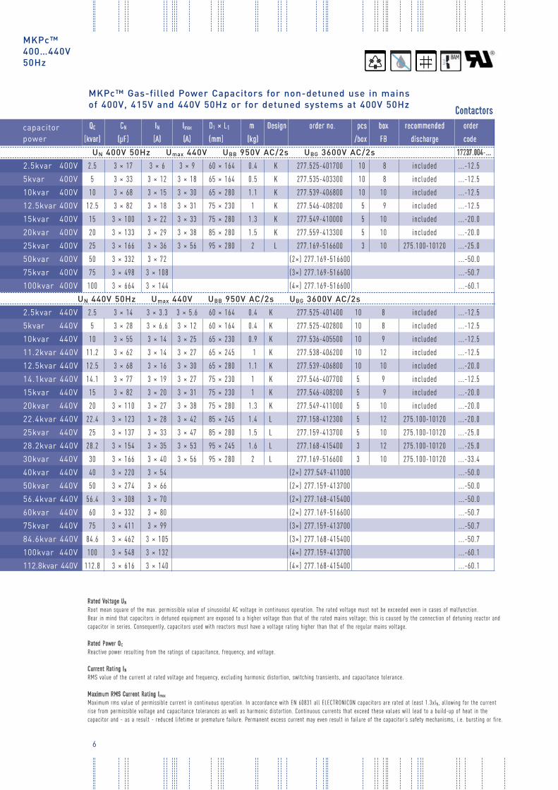
MKPc™ Gas-filled Power Capacitors for non-detuned use in mains
of 400V, 415V and 440V 50Hz or for detuned systems at 400V 50Hz
capacitor
power
MKPc™
400…440V
50Hz
Contactors
Rated Voltage UN
Root mean square of the max. permissible value of sinusoidal AC voltage in continuous operation. The rated voltage must not be exceeded even in cases of malfunction.
Bear in mind that capacitors in detuned equipment are exposed to a higher voltage than that of the rated mains voltage; this is caused by the connection of detuning reactor and
capacitor in series. Consequently, capacitors used with reactors must have a voltage rating higher than that of the regular mains voltage.
Rated Power QC
Reactive power resulting from the ratings of capacitance, frequency, and voltage.
Current Rating IN
RMS value of the current at rated voltage and frequency, excluding harmonic distortion, switching transients, and capacitance tolerance.
Maximum RMS Current Rating Imax
Maximum rms value of permissible current in continuous operation. In accordance with EN 60831 all ELECTRONICON capacitors are rated at least 1.3xIN, allowing for the current
rise from permissible voltage and capacitance tolerances as well as harmonic distortion. Continuous currents that exceed these values will lead to a build-up of heat in the
capacitor and - as a result - reduced lifetime or premature failure. Permanent excess current may even result in failure of the capacitor’s safety mechanisms, i.e. bursting or fire.
QC CN IN Imax D1 × L1 m Design order no. pcs box recommended order
(kvar) (μF) (A) (A) (mm) (kg) /box FB discharge code
UN 400V 50Hz Umax 440V UBB 950V AC/2s UBG 3600V AC/2s 17237.004-...
2.5kvar 400V 2.5 3 × 17 3 × 6 3 × 9 60 × 164 0.4 K 277.525-401700 10 8 included ...-12.5
5kvar 400V 5 3 × 33 3 × 12 3 × 18 65 × 164 0.5 K 277.535-403300 10 8 included ...-12.5
10kvar 400V 10 3 × 68 3 × 15 3 × 30 65 × 280 1.1 K 277.539-406800 10 10 included ...-12.5
12.5kvar 400V 12.5 3 × 82 3 × 18 3 × 31 75 × 230 1 K 277.546-408200 5 9 included ...-12.5
15kvar 400V 15 3 × 100 3 × 22 3 × 33 75 × 280 1.3 K 277.549-410000 5 10 included ...-20.0
20kvar 400V 20 3 × 133 3 × 29 3 × 38 85 × 280 1.5 K 277.559-413300 5 10 included ...-20.0
25kvar 400V 25 3 × 166 3 × 36 3 × 56 95 × 280 2 L 277.169-516600 3 10 275.100-10120 ...-25.0
50kvar 400V 50 3 × 332 3 × 72 (2×) 277.169-516600 ...-50.0
75kvar 400V 75 3 × 498 3 × 10⁸ (3×) 277.169-516600 ...-50.7
100kvar 400V 100 3 × 664 3 × 144 (4×) 277.169-516600 ...-60.1
UN 440V 50Hz Umax 440V UBB 950V AC/2s UBG 3600V AC/2s
2.5kvar 440V 2.5 3 × 14 3 × 3.3 3 × 5.6 60 × 164 0.4 K 277.525-401400 10 8 included ...-12.5
5kvar 440V 5 3 × 28 3 × 6.6 3 × 12 60 × 164 0.4 K 277.525-402800 10 8 included ...-12.5
10kvar 440V 10 3 × 55 3 × 14 3 × 25 65 × 230 0.9 K 277.536-405500 10 9 included ...-12.5
11.2kvar 440V 11.2 3 × 62 3 × 14 3 × 27 65 × 245 1 K 277.538-406200 10 12 included ...-12.5
12.5kvar 440V 12.5 3 × 68 3 × 16 3 × 30 65 × 280 1.1 K 277.539-406800 10 10 included ...-20.0
14.1kvar 440V 14.1 3 × 77 3 × 19 3 × 27 75 × 230 1 K 277.546-407700 5 9 included ...-12.5
15kvar 440V 15 3 × 82 3 × 20 3 × 31 75 × 230 1 K 277.546-408200 5 9 included ...-20.0
20kvar 440V 20 3 × 110 3 × 27 3 × 38 75 × 280 1.3 K 277.549-411000 5 10 included ...-20.0
22.4kvar 440V 22.4 3 × 123 3 × 28 3 × 42 85 × 245 1.4 L 277.158-412300 5 12 275.100-10120 ...-20.0
25kvar 440V 25 3 × 137 3 × 33 3 × 47 85 × 280 1.5 L 277.159-413700 5 10 275.100-10120 ...-25.0
28.2kvar 440V 28.2 3 × 154 3 × 35 3 × 53 95 × 245 1.6 L 277.168-415400 3 12 275.100-10120 ...-25.0
30kvar 440V 30 3 × 166 3 × 40 3 × 56 95 × 280 2 L 277.169-516600 3 10 275.100-10120 ...-33.4
40kvar 440V 40 3 × 220 3 × 54 (2×) 277.549-411000 ...-50.0
50kvar 440V 50 3 × 274 3 × 66 (2×) 277.159-413700 ...-50.0
56.4kvar 440V 56.4 3 × 308 3 × 70 (2×) 277.168-415400 ...-50.0
60kvar 440V 60 3 × 332 3 × 80 (2×) 277.169-516600 ...-50.7
75kvar 440V 75 3 × 411 3 × 99 (3×) 277.159-413700 ...-50.7
84.6kvar 440V 84.6 3 × 462 3 × 10⁵ (3×) 277.168-415400 ...-50.7
100kvar 440V 100 3 × 548 3 × 132 (4×) 277.159-413700 ...-60.1
112.8kvar 440V 112.8 3 × 616 3 × 140 (4×) 277.168-415400 ...-60.1
7
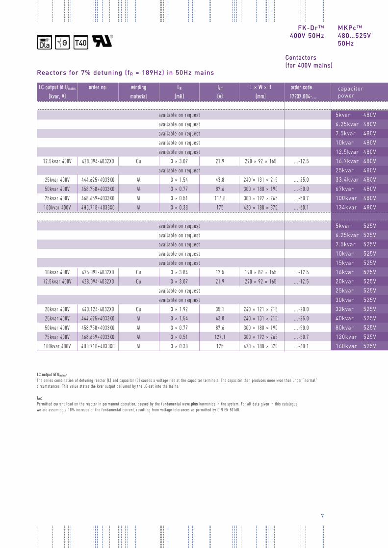
Reactors for 7% detuning (fR = 189Hz) in 50Hz mains
LC output @ Umains:
The series combination of detuning reactor (L) and capacitor (C) causes a voltage rise at the capacitor terminals. The capacitor then produces more kvar than under “normal”
circumstances. This value states the kvar output delivered by the LC-set into the mains.
Ieff:
Permitted current load on the reactor in permanent operation, caused by the fundamental wave plus harmonics in the system. For all data given in this catalogue,
we are assuming a 10% increase of the fundamental current, resulting from voltage tolerances as permitted by DIN EN 50160.
LC output @ Umains order no. winding LN Ieff L × W × H order code
(kvar, V) material (mH) (A) (mm) 17237.004-...
available on request
available on request
available on request
available on request
available on request
12.5kvar 400V 428.094-4032X0 Cu 3 × 3.07 21.9 290 × 92 × 165 ...-12.5
available on request
25kvar 400V 444.625+4033X0 Al 3 × 1.54 43.8 240 × 131 × 215 ...-25.0
50kvar 400V 458.758+4033X0 Al 3 × 0.77 87.6 300 × 180 × 190 ...-50.0
75kvar 400V 468.659+4033X0 Al 3 × 0.51 116.8 300 × 192 × 265 ...-50.7
100kvar 400V 4H0.718+4033X0 Al 3 × 0.38 175 420 × 188 × 370 ...-60.1
available on request
available on request
available on request
available on request
available on request
10kvar 400V 425.093-4032X0 Cu 3 × 3.84 17.5 190 × 82 × 165 ...-12.5
12.5kvar 400V 428.094-4032X0 Cu 3 × 3.07 21.9 290 × 92 × 165 ...-12.5
available on request
available on request
20kvar 400V 440.124-4032X0 Cu 3 × 1.92 35.1 240 × 121 × 215 ...-20.0
25kvar 400V 444.625+4033X0 Al 3 × 1.54 43.8 240 × 131 × 215 ...-25.0
50kvar 400V 458.758+4033X0 Al 3 × 0.77 87.6 300 × 180 × 190 ...-50.0
75kvar 400V 468.659+4033X0 Al 3 × 0.51 127.1 300 × 192 × 265 ...-50.7
100kvar 400V 4H0.718+4033X0 Al 3 × 0.38 175 420 × 188 × 370 ...-60.1
MKPc™480…525V50Hz
capacitorpower
5kvar 480V
6.25kvar 480V
7.5kvar 480V
10kvar 480V
12.5kvar 480V
16.7kvar 480V
25kvar 480V
33.4kvar 480V
67kvar 480V
100kvar 480V
134kvar 480V
5kvar 525V
6.25kvar 525V
7.5kvar 525V
10kvar 525V
15kvar 525V
16kvar 525V
20kvar 525V
25kvar 525V
30kvar 525V
32kvar 525V
40kvar 525V
80kvar 525V
120kvar 525V
160kvar 525V
Contactors
(for 400V mains)
FK-Dr™
400V 50Hz
8
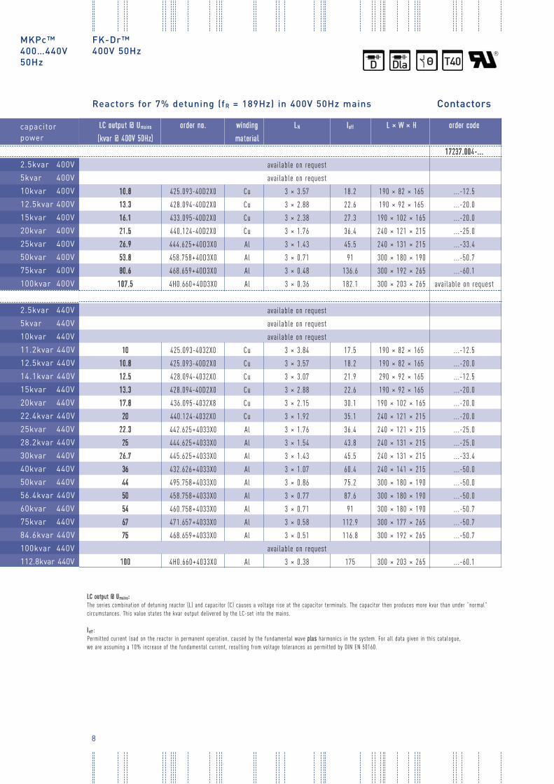
LC output @ Umains order no. winding LN Ieff L × W × H order code
(kvar @ 400V 50Hz) material
17237.004-...
available on request
available on request
10.8 425.093-40D2X0 Cu 3 × 3.57 18.2 190 × 82 × 165 ...-12.5
13.3 428.094-40D2X0 Cu 3 × 2.88 22.6 190 × 92 × 165 ...-20.0
16.1 433.095-40D2X0 Cu 3 × 2.38 27.3 190 × 102 × 165 ...-20.0
21.5 440.124-40D2X0 Cu 3 × 1.76 36.4 240 × 121 × 215 ...-25.0
26.9 444.625+40D3X0 Al 3 × 1.43 45.5 240 × 131 × 215 ...-33.4
53.8 458.758+40D3X0 Al 3 × 0.71 91 300 × 180 × 190 ...-50.7
80.6 468.659+40D3X0 Al 3 × 0.48 136.6 300 × 192 × 265 ...-60.1
107.5 4H0.660+40D3X0 Al 3 × 0.36 182.1 300 × 203 × 265 available on request
available on request
available on request
available on request
10 425.093-4032X0 Cu 3 × 3.84 17.5 190 × 82 × 165 ...-12.5
10.8 425.093-40D2X0 Cu 3 × 3.57 18.2 190 × 82 × 165 ...-20.0
12.5 428.094-4032X0 Cu 3 × 3.07 21.9 290 × 92 × 165 ...-12.5
13.3 428.094-40D2X0 Cu 3 × 2.88 22.6 190 × 92 × 165 ...-20.0
17.8 436.095-4032X8 Cu 3 × 2.15 30.1 190 × 102 × 165 ...-20.0
20 440.124-4032X0 Cu 3 × 1.92 35.1 240 × 121 × 215 ...-20.0
22.3 442.625+4033X0 Al 3 × 1.76 36.4 240 × 121 × 215 ...-25.0
25 444.625+4033X0 Al 3 × 1.54 43.8 240 × 131 × 215 ...-25.0
26.7 445.625+4033X0 Al 3 × 1.43 45.5 240 × 131 × 215 ...-33.4
36 432.626+4033X0 Al 3 × 1.07 60.4 240 × 141 × 215 ...-50.0
44 495.758+4033X0 Al 3 × 0.86 75.2 300 × 180 × 190 ...-50.0
50 458.758+4033X0 Al 3 × 0.77 87.6 300 × 180 × 190 ...-50.0
54 460.758+4033X0 Al 3 × 0.71 91 300 × 180 × 190 ...-50.7
67 471.657+4033X0 Al 3 × 0.58 112.9 300 × 177 × 265 ...-50.7
75 468.659+4033X0 Al 3 × 0.51 116.8 300 × 192 × 265 ...-50.7
available on request
100 4H0.660+4033X0 Al 3 × 0.38 175 300 × 203 × 265 ...-60.1
LC output @ Umains:
The series combination of detuning reactor (L) and capacitor (C) causes a voltage rise at the capacitor terminals. The capacitor then produces more kvar than under “normal”
circumstances. This value states the kvar output delivered by the LC-set into the mains.
Ieff :
Permitted current load on the reactor in permanent operation, caused by the fundamental wave plus harmonics in the system. For all data given in this catalogue,
we are assuming a 10% increase of the fundamental current, resulting from voltage tolerances as permitted by DIN EN 50160.
Reactors for 7% detuning (fR = 189Hz) in 400V 50Hz mains
FK-Dr™
400V 50Hz
Contactors
capacitor power
MKPc™400…440V50Hz
2.5kvar 400V
5kvar 400V
10kvar 400V
12.5kvar 400V
15kvar 400V
20kvar 400V
25kvar 400V
50kvar 400V
75kvar 400V
100kvar 400V
2.5kvar 440V
5kvar 440V
10kvar 440V
11.2kvar 440V
12.5kvar 440V
14.1kvar 440V
15kvar 440V
20kvar 440V
22.4kvar 440V
25kvar 440V
28.2kvar 440V
30kvar 440V
40kvar 440V
50kvar 440V
56.4kvar 440V
60kvar 440V
75kvar 440V
84.6kvar 440V
100kvar 440V
112.8kvar 440V

9
LC output @ Umains:
The series combination of detuning reactor (L) and capacitor (C) causes a voltage rise at the capacitor terminals. The capacitor then produces more kvar than under “normal”
circumstances. This value states the kvar output delivered by the LC-set into the mains.
Ieff:
Permitted current load on the reactor in permanent operation, caused by the fundamental wave plus harmonics in the system. For all data given in this catalogue,
we are assuming a 10% increase of the fundamental current, resulting from voltage tolerances as permitted by DIN EN 50160.
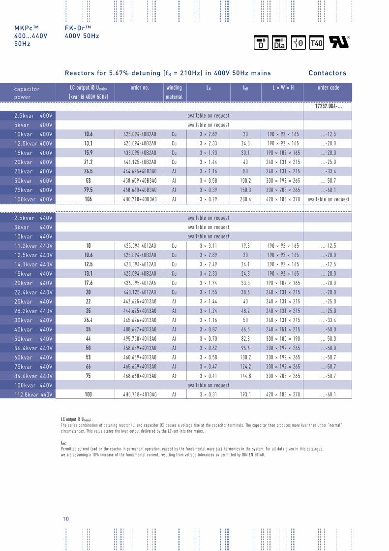
Reactors for 5.67% detuning (fR = 210Hz) in 50Hz mains
FK-Dr™
400/415V 50Hz
LC output @ Umains order no. winding LN Ieff L × W × H order code
(kvar. V) material (mH) (A) (mm) 17237.004-...
available on request
available on request
available on request
available on request
available on request
12.5kvar 400V 428.094-4012A0 3 × 2.49 24.1 190 × 92 × 165 ...-12.5
available on request
25kvar 400V 444.625+4013A0 3 × 1.24 48.2 240 × 131 × 215 ...-25.0
50kvar 400V 458.659+4013A0 3 × 0.62 96.6 300 × 192 × 265 ...-50.0
75kvar 400V 468.660+4013A0 3 × 0.41 144.8 300 × 203 × 265 ...-50.7
100kvar 400V 4H0.718+4013A0 3 × 0.31 193.1 420 × 188 × 370 ...-60.1
available on request
available on request
available on request
available on request
available on request
10kvar 400V 425.094-4012A0 3 × 3.11 19.3 190 × 92 × 165 ...-12.5
12.5kvar 400V 428.094-4012A0 3 × 2.49 24.1 190 × 92 × 165 ...-12.5
available on request
available on request
20kvar 400V 440.125-4012A0 3 × 1.55 38.6 240 × 131 × 215 ...-20.0
25kvar 400V 444.625+4013A0 3 × 1.24 48.2 240 × 131 × 215 ...-25.0
50kvar 400V 458.659+4013A0 3 × 0.62 96.6 300 × 192 × 265 ...-50.0
75kvar 400V 468.660+4013A0 3 × 0.41 144.8 300 × 203 × 265 ...-50.7
100kvar 400V 4H0.718+4013A0 3 × 0.31 193.1 420 × 188 × 370 ...-60.1
MKPc™480…525V50Hz
capacitorpower
5kvar 480V
6.25kvar 480V
7.5kvar 480V
10kvar 480V
12.5kvar 480V
16.7kvar 480V
25kvar 480V
33.4kvar 480V
67kvar 480V
100kvar 480V
134kvar 480V
5kvar 525V
6.25kvar 525V
7.5kvar 525V
10kvar 525V
15kvar 525V
16kvar 525V
20kvar 525V
25kvar 525V
30kvar 525V
32kvar 525V
40kvar 525V
80kvar 525V
120kvar 525V
160kvar 525V
Contactors
(for 400V mains)
10
Reactors for 5.67% detuning (fR = 210Hz) in 400V 50Hz mains
FK-Dr™
400V 50Hz
Contactors
LC output @ Umains:
The series combination of detuning reactor (L) and capacitor (C) causes a voltage rise at the capacitor terminals. The capacitor then produces more kvar than under “normal”
circumstances. This value states the kvar output delivered by the LC-set into the mains.
Ieff:
Permitted current load on the reactor in permanent operation, caused by the fundamental wave plus harmonics in the system. For all data given in this catalogue,
we are assuming a 10% increase of the fundamental current, resulting from voltage tolerances as permitted by DIN EN 50160.
LC output @ Umains order no. winding LN Ieff L × W × H order code
(kvar @ 400V 50Hz) material
17237.004-...
available on request
available on request
10.6 425.094-40B2A0 Cu 3 × 2.89 20 190 × 92 × 165 ...-12.5
13.1 428.094-40B2A0 Cu 3 × 2.33 24.8 190 × 92 × 165 ...-20.0
15.9 433.095-40B2A0 Cu 3 × 1.93 30.1 190 × 102 × 165 ...-20.0
21.2 444.125-40B2A0 Cu 3 × 1.44 40 240 × 131 × 215 ...-25.0
26.5 444.625+40B3A0 Al 3 × 1.16 50 240 × 131 × 215 ...-33.4
53 458.659+40B3A0 Al 3 × 0.58 100.2 300 × 192 × 265 ...-50.7
79.5 468.660+40B3A0 Al 3 × 0.39 150.3 300 × 203 × 265 ...-60.1
106 4H0.718+40B3A0 Al 3 × 0.29 200.4 420 × 188 × 370 available on request
available on request
available on request
available on request
10 425.094-4012A0 Cu 3 × 3.11 19.3 190 × 92 × 165 ...-12.5
10.6 425.094-40B2A0 Cu 3 × 2.89 20 190 × 92 × 165 ...-20.0
12.5 428.094-4012A0 Cu 3 × 2.49 24.1 290 × 92 × 165 ...-12.5
13.1 428.094-40B2A0 Cu 3 × 2.33 24.8 190 × 92 × 165 ...-20.0
17.6 436.095-4012A6 Cu 3 × 1.74 33.3 190 × 102 × 165 ...-20.0
20 440.125-4012A0 Cu 3 × 1.55 38.6 240 × 131 × 215 ...-20.0
22 442.625+4013A0 Al 3 × 1.44 40 240 × 131 × 215 ...-25.0
25 444.625+4013A0 Al 3 × 1.24 48.2 240 × 131 × 215 ...-25.0
26.4 445.626+4013A0 Al 3 × 1.16 50 240 × 131 × 215 ...-33.4
35 488.627+4013A0 Al 3 × 0.87 66.5 240 × 151 × 215 ...-50.0
44 495.758+4013A0 Al 3 × 0.70 82.8 300 × 180 × 190 ...-50.0
50 458.659+4013A0 Al 3 × 0.62 96.6 300 × 192 × 265 ...-50.0
53 460.659+4013A0 Al 3 × 0.58 100.2 300 × 192 × 265 ...-50.7
66 465.659+4013A0 Al 3 × 0.47 124.2 300 × 192 × 265 ...-50.7
75 468.660+4013A0 Al 3 × 0.41 144.8 300 × 203 × 265 ...-50.7
available on request
100 4H0.718+4013A0 Al 3 × 0.31 193.1 420 × 188 × 370 ...-60.1
capacitor power
MKPc™400…440V50Hz
2.5kvar 400V
5kvar 400V
10kvar 400V
12.5kvar 400V
15kvar 400V
20kvar 400V
25kvar 400V
50kvar 400V
75kvar 400V
100kvar 400V
2.5kvar 440V
5kvar 440V
10kvar 440V
11.2kvar 440V
12.5kvar 440V
14.1kvar 440V
15kvar 440V
20kvar 440V
22.4kvar 440V
25kvar 440V
28.2kvar 440V
30kvar 440V
40kvar 440V
50kvar 440V
56.4kvar 440V
60kvar 440V
75kvar 440V
84.6kvar 440V
100kvar 440V
112.8kvar 440V
11
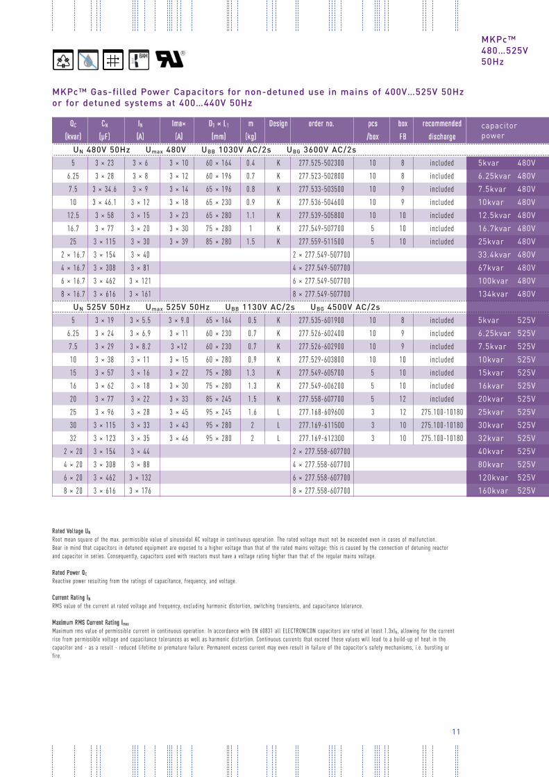
MKPc™ Gas-filled Power Capacitors for non-detuned use in mains of 400V…525V 50Hz
or for detuned systems at 400…440V 50Hz
MKPc™
480…525V
50Hz
capacitor
power
Rated Voltage UN
Root mean square of the max. permissible value of sinusoidal AC voltage in continuous operation. The rated voltage must not be exceeded even in cases of malfunction.
Bear in mind that capacitors in detuned equipment are exposed to a higher voltage than that of the rated mains voltage; this is caused by the connection of detuning reactor
and capacitor in series. Consequently, capacitors used with reactors must have a voltage rating higher than that of the regular mains voltage.
Rated Power QC
Reactive power resulting from the ratings of capacitance, frequency, and voltage.
Current Rating IN
RMS value of the current at rated voltage and frequency, excluding harmonic distortion, switching transients, and capacitance tolerance.
Maximum RMS Current Rating Imax
Maximum rms value of permissible current in continuous operation. In accordance with EN 60831 all ELECTRONICON capacitors are rated at least 1.3xIN, allowing for the current
rise from permissible voltage and capacitance tolerances as well as harmonic distortion. Continuous currents that exceed these values will lead to a build-up of heat in the
capacitor and - as a result - reduced lifetime or premature failure. Permanent excess current may even result in failure of the capacitor’s safety mechanisms, i.e. bursting or
fire.
QC CN IN Ima× D1 × L1 m Design order no. pcs box recommended
(kvar) (μF) (A) (A) (mm) (kg) /box FB discharge
UN 480V 50Hz Umax 480V UBB 1030V AC/2s UBG 3600V AC/2s
5 3 × 23 3 × 6 3 × 10 60 × 164 0.4 K 277.525-502300 10 8 included 5kvar 480V
6.25 3 × 28 3 × 8 3 × 12 60 × 196 0.7 K 277.523-502800 10 8 included 6.25kvar 480V
7.5 3 × 34.6 3 × 9 3 × 14 65 × 196 0.8 K 277.533-503500 10 9 included 7.5kvar 480V
10 3 × 46.1 3 × 12 3 × 18 65 × 230 0.9 K 277.536-504600 10 9 included 10kvar 480V
12.5 3 × 58 3 × 15 3 × 23 65 × 280 1.1 K 277.539-505800 10 10 included 12.5kvar 480V
16.7 3 × 77 3 × 20 3 × 30 75 × 280 1 K 277.549-507700 5 10 included 16.7kvar 480V
25 3 × 115 3 × 30 3 × 39 85 × 280 1.5 K 277.559-511500 5 10 included 25kvar 480V
2 × 16.7 3 × 154 3 × 40 2 × 277.549-507700 33.4kvar 480V
4 × 16.7 3 × 308 3 × 81 4 × 277.549-507700 67kvar 480V
6 × 16.7 3 × 462 3 × 121 6 × 277.549-507700 100kvar 480V
8 × 16.7 3 × 616 3 × 161 8 × 277.549-507700 134kvar 480V
UN 525V 50Hz Umax 525V 50Hz UBB 1130V AC/2s UBG 4500V AC/2s
5 3 × 19 3 × 5.5 3 × 9.0 65 × 164 0.5 K 277.535-601900 10 8 included 5kvar 525V
6.25 3 × 24 3 × 6.9 3 × 11 60 × 230 0.7 K 277.526-602400 10 9 included 6.25kvar 525V
7.5 3 × 29 3 × 8.2 3 ×12 60 × 230 0.7 K 277.526-602900 10 9 included 7.5kvar 525V
10 3 × 38 3 × 11 3 × 15 60 × 280 0.9 K 277.529-603800 10 10 included 10kvar 525V
15 3 × 57 3 × 16 3 × 22 75 × 280 1.3 K 277.549-605700 5 10 included 15kvar 525V
16 3 × 62 3 × 18 3 × 30 75 × 280 1.3 K 277.549-606200 5 10 included 16kvar 525V
20 3 × 77 3 × 22 3 × 33 85 × 245 1.5 K 277.558-607700 5 12 included 20kvar 525V
25 3 × 96 3 × 28 3 × 45 95 × 245 1.6 L 277.168-609600 3 12 275.100-10180 25kvar 525V
30 3 × 115 3 × 33 3 × 43 95 × 280 2 L 277.169-611500 3 10 275.100-10180 30kvar 525V
32 3 × 123 3 × 35 3 × 46 95 × 280 2 L 277.169-612300 3 10 275.100-10180 32kvar 525V
2 × 20 3 × 154 3 × 44 2 × 277.558-607700 40kvar 525V
4 × 20 3 × 308 3 × 88 4 × 277.558-607700 80kvar 525V
6 × 20 3 × 462 3 × 132 6 × 277.558-607700 120kvar 525V
8 × 20 3 × 616 3 × 176 8 × 277.558-607700 160kvar 525V
17237.004-...
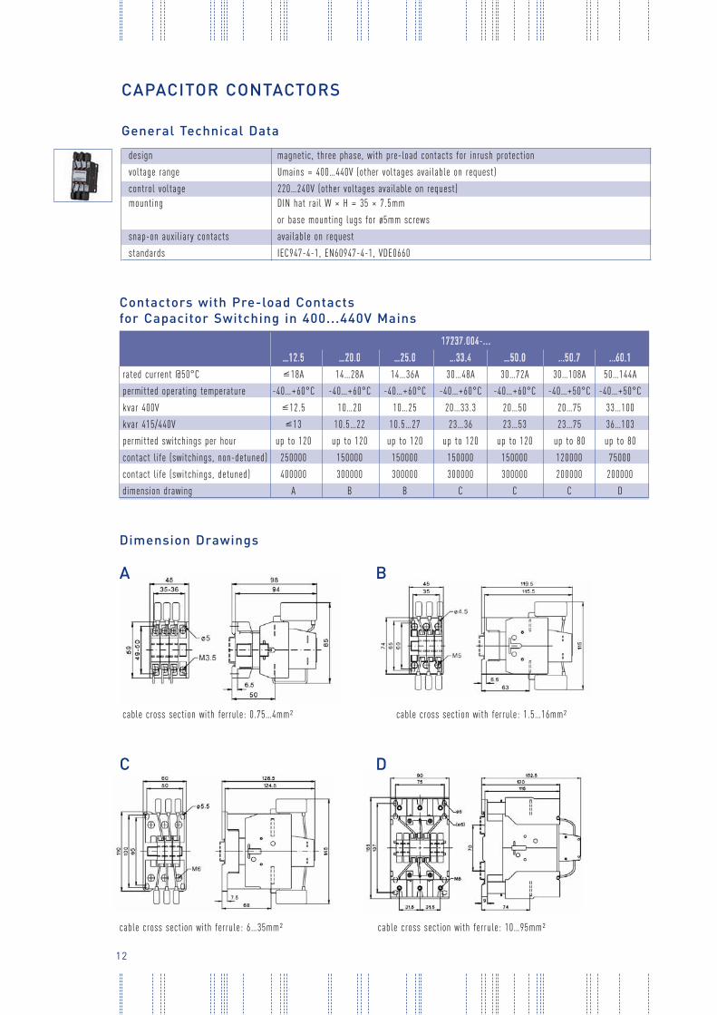
…12.5 …20.0 …25.0 …33.4 …50.0 …50.7 …60.1
rated current @50°C �18A 14…28A 14…36A 30…48A 30…72A 30…108A 50…144A
permitted operating temperature -40…+60°C -40…+60°C -40…+60°C -40…+60°C -40…+60°C -40…+50°C -40…+50°C
kvar 400V �12.5 10…20 10…25 20…33.3 20…50 20…75 33…100
kvar 415/440V �13 10.5…22 10.5…27 23…36 23…53 23…75 36…103
permitted switchings per hour up to 120 up to 120 up to 120 up to 120 up to 120 up to 80 up to 80
contact life (switchings, non-detuned) 250000 150000 150000 150000 150000 120000 75000
contact life (switchings, detuned) 400000 300000 300000 300000 300000 200000 200000
dimension drawing A B B C C C D
12
design magnetic, three phase, with pre-load contacts for inrush protection
voltage range Umains = 400…440V (other voltages available on request)
control voltage 220…240V (other voltages available on request)
mounting DIN hat rail W × H = 35 × 7.5mm
or base mounting lugs for ø5mm screws
snap-on auxiliary contacts available on request
standards IEC947-4-1, EN60947-4-1, VDE0660
General Technical Data
Contactors with Pre-load Contacts
for Capacitor Switching in 400...440V Mains
CAPACITOR CONTACTORS
Dimension Drawings
A B
C D
cable cross section with ferrule: 1.5…16mm²cable cross section with ferrule: 0.75…4mm²
cable cross section with ferrule: 10…95mm²cable cross section with ferrule: 6…35mm²
13
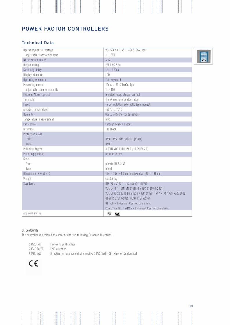
Technical Data
POWER FACTOR CONTROLLERS
Operation/Control voltage 90- 550V AC, 45 … 65HZ, 5VA, 1ph
adjustable transformer ratio 1 … 350
No of output relays 6.12
Output rating 250V AC / 5A
Switching delay 1s … 1200s
Display elements LCD
Operating elements Foil keyboard
Measuring current 10mA … 6A, 20mΩ , 1ph
adjustable transformer ratio 1...4000
External Alarm contact isolated relay, closed contact
Terminals 4mm² multiple contact plug
Fuses to be installed externally (see manual)
Ambient temperature -20°C … 70°C
Humidity 0% … 98% (no condensation)
Temperature measurement NTC
Fan control through branch output
Interface TTL (back)
Protection class
Front IP50 (IP54 with special gasket)
Back IP20
Pollution degree 3 (DIN VDE 0110, Pt 1 / IEC60664-1)
Mounting position no restrictions
Case
Front plastic (UL94: V0)
Back metal
Dimensions H × W × D 144 × 144 × 58mm (window size 138 × 138mm)
Weight ca. 0.6 kg
Standards DIN VDE 0110 1 (IEC 60664-1:1992)
VDE 0411 1 (DIN EN 61010-1 / IEC 61010-1:2001)
VDE 0843 20 (DIN EN 61326 / IEC 61326: 1997 + A1:1998 +A2: 2000)
GOST R 52319-2005, GOST R 51522-99
UL 508 – Industrial Control Equipment
CSA C22.2 No. 14-M95 - Industrial Control Equipment
Approval marks
CE Conformity
The controller is declared to conform with the following European Directives:
73/23/EWG Low-Voltage Directive
2004/108/EG EMC directive
93/68/EWG Directive for amendment of directive 73/23/EWG (CE- Mark of Conformity)

IMPORTANT
12 Months Limited WarrantyAll our products are designed, manufactured, and tested with the high-est care and workmanship. The satisfaction of our customers is ourhighest goal. We therefore warrant remedying any defect in thegoods resulting from faulty design, materials or workmanship, whichappears within 12 months from the date of sale.
This warranty does not cover defects due to improper use of thegoods or operation at conditions exceeding the rated values statedin the catalogue or special data sheet. Nor does it cover defectsdue to faulty maintenance or incorrect installation, alterations or faultyrepairs undertaken by the Buyer. Finally the warranty does not covernormal wear and tear or deterioration.
Protection Against Overvoltages and Short Circuits: Self-Healing Dielectric All dielectric structures used in our power capacitors are “self-healing”: In the event of a voltage breakdown the metal layersaround the breakdown channel are evaporated by the temperatureof the electric arc that forms between the electrodes. They are removedwithin a few microseconds and pushed apart by the pressure gen-erated in the centre of the breakdown spot. An insulation area is formedwhich is reliably resistive and voltage proof for all operating require-ments of the capacitor. The capacitor remains fully functional dur-ing and after the breakdown. For voltages within the permitted testing and operating limits thecapacitors are short-circuit- and overvoltage-proof. They are also proof against external short circuits as far as the result-ing surge discharges do not exceed the specified surge current lim-its.
Mounting and CoolingThe useful life of a capacitor may be reduced dramatically if exposedto excessive heat. Typically an increase in the ambient temperatureof 7°C will halve the expected life of the capacitor. Make sure toobey the permitted operating temperatures of ambient temperatureclass D (max. temperature 55°C, max. average over 24hrs. 45°C,max. average over 365 days 35°C). To avoid overheating the capacitors must be allowed to cool unhin-dered and should be shielded from external heat sources. We rec-ommend forced ventilation for all applications with detuning reactors.Give at least 20mm clearance between the capacitors for natural orforced ventilation, and do not place them directly above or next to heatsources such as detuning or tuning reactors, bus bars, etc.
Functioning of the BAM™ (Break Action Mechanism) In the event of overvoltage or thermal overload or ageing at the endof the capacitor's useful service life, an increasing number of self-healing breakdowns may cause rising pressure inside the capacitor.To prevent it from bursting, the capacitor is f itted with an obliga-tory “break action mechanism” (BAM). The BAM™ is based on an atten-uated spot at one of the connecting wires inside the capacitor. Withrising pressure the case begins to expand, mainly by opening thefolded crimp and pushing the lid upwards. As a result, the preparedconnecting wire is separated at the attenuated spot, and the cur-rent path is interrupted irreversibly.
Warning:It has to be noted that this safety system can act properly onlywithin the permitted limits of loads and overloads. The simple pres-ence of a safety mechanism does not mean that catastrophic fail-ures are completely impossible. Strong overvoltages, permanent exter-nal heat, and heavy current overload, e.g. during harmonic resonancesmay cause sudden, uncontrollable rise of temperature and pressureinside the can which may not leave suff icient t ime for the BAM™
to act properly, and result in explosion and fire.
SafetyELECTRONICON will not indemnify or be responsible for any kind ofdamages to persons or property due to the improper application ofany capacitors or reactors purchased from ELECTRONICON or its dis-tributors. The capacitors and reactors should only be used for the appli-cation intended.
Mind that electrical or mechanical misapplication of capacitors andreactors can become hazardous. Misapplied capacitors can explodeor catch fire and cause bodily injury or property damage due to theexpulsion of material or metal fragments.
Please consult the detailed instructions for mounting and applica-tion stated in our Catalogue brochure “Capacitors and Reactors ForPower Factor Correction”, and on the ELECTRONICON website. If indoubt about how to connect, operate, or discharge a capacitor, con-sult ELECTRONICON engineering.
For more detailed information, please order our comprehensive catalogue “Capacitors and Reactors for Power Factor Correction”, and the “General Safety Advice for Power Capacitors” issued by the German Electrical and Electronic Manufacturer’s Association (ZVEI).
See our “General Conditions” for details on Warranty and Product liability.
14
IMPORTANT REMARKS
APPROVED
15
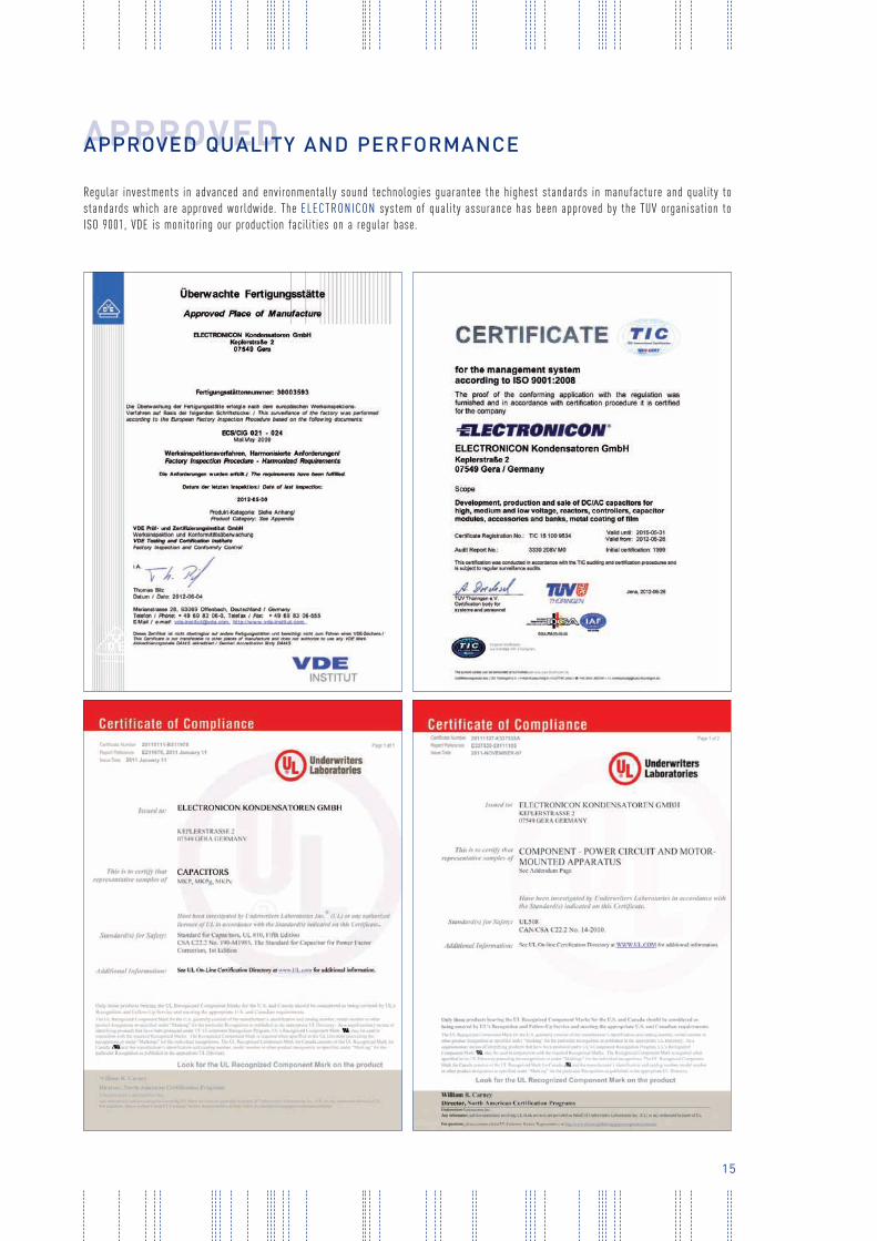
Regular investments in advanced and environmentally sound technologies guarantee the highest standards in manufacture and quality tostandards which are approved worldwide. The ELECTRONICON system of quality assurance has been approved by the TUV organisation toISO 9001, VDE is monitoring our production facilities on a regular base.
APPROVED QUALITY AND PERFORMANCE
16
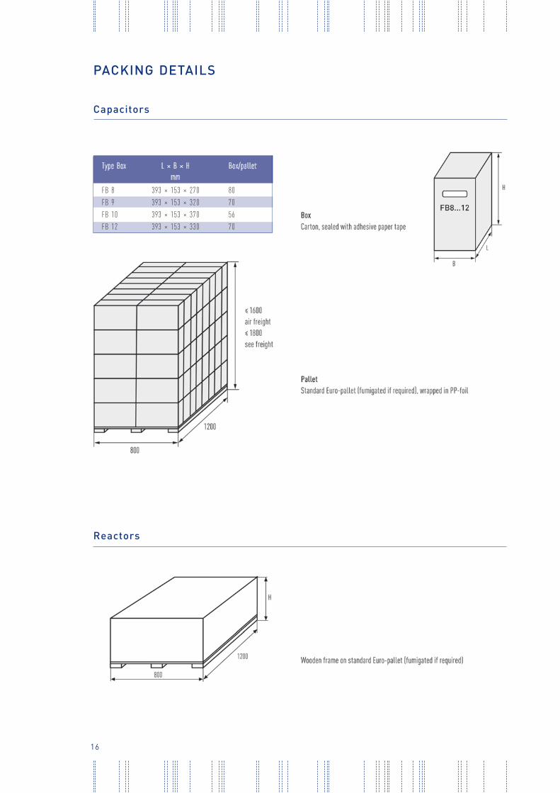
PACKING DETAILS
Type Box L × B × H Box/pallet
mm
FB 8 393 × 153 × 270 80
FB 9 393 × 153 × 320 70
FB 10 393 × 153 × 370 56
FB 12 393 × 153 × 330 70
Capacitors
Reactors

17
cEL
ECTR
ONIC
ON K
onde
nsat
oren
Gm
bH.
All
righ
ts r
eser
ved.
We
rese
rve
the
righ
t to
mak
e te
chni
cal
chan
ges
wit
hout
pri
or n
otic
e. N
o lia
bilit
y ca
n be
ass
umed
for
the
acc
urac
y of
dat
a co
nten
t. I
ssue
01/
2013
are
regi
ster
ed t
rade
mar
ks o
f EL
ECTR
ONIC
ON K
onde
nsat
oren
Gm
bH.
BAM
™,
FK-D
r™,
MKP
c™ a
nd M
KPg™
ar
e tr
adem
arks
of
ELEC
TRON
ICON
Kon
dens
ator
en G
mbH
.
200.
003-
0200
18.
,
,
In today's globalised competition, we distinguish ourselves by
Absolute reliability and safety of our products
Close co-operation between manufacturer and client
to meet both technical and commercial requirements
Improvement and development of our technical expertise
in capacitor design and manufacture, as well as f ilm coating,
with special attention paid to the MKPg-technology
Early identif ication and incorporation of new trends
and methods in the manufacturing of capacitors
Flexibility and punctual fulfilment of our commercial obligations
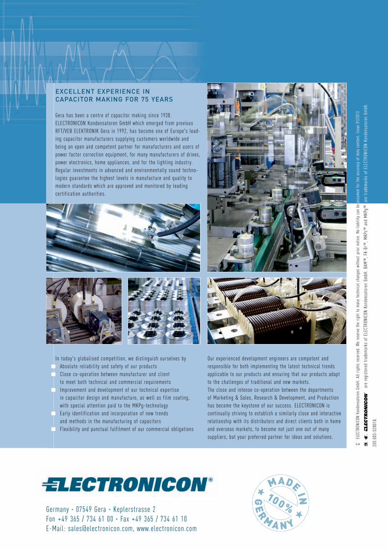
EXCELLENT EXPERIENCE IN
CAPACITOR MAKING FOR 75 YEARS
Gera has been a centre of capacitor making since 1938.
ELECTRONICON Kondensatoren GmbH which emerged from previous
RFT/VEB ELEKTRONIK Gera in 1992, has become one of Europe's lead-
ing capacitor manufacturers supplying customers worldwide and
being an open and competent partner for manufacturers and users of
power factor correction equipment, for many manufacturers of drives,
power electronics, home appliances, and for the lighting industry.
Regular investments in advanced and environmentally sound techno-
logies guarantee the highest levels in manufacture and quality to
modern standards which are approved and monitored by leading
certif ication authorities.
Our experienced development engineers are competent and
responsible for both implementing the latest technical trends
applicable to our products and ensuring that our products adapt
to the challenges of traditional and new markets.
The close and intense co-operation between the departments
of Marketing & Sales, Research & Development, and Production
has become the keystone of our success. ELECTRONICON is
continually striving to establish a similarly close and interactive
relationship with its distributors and direct clients both in home
and overseas markets, to become not just one out of many
suppliers, but your preferred partner for ideas and solutions.
Germany · 07549 Gera · Keplerstrasse 2Fon +49 365 / 734 61 00 · Fax +49 365 / 734 61 10E-Mail: [email protected], www.electronicon.com
Recommended