Calibration of Oscillator
Phase Noise Measurement
Instruments
Version 010e Jörn Bartels, DK7JB 49088 Osnabrück
[email protected] http://www.bartelsos.de/dk7jb.php
14. September 2016

Calibration of Oscillator Phase Noise Instruments Document: DK7JB_OscillatorPhaseNoiseCalibration_010e.docx Jörn DK7JB [email protected]
3 von 17
Inhaltsverzeichnis
1 Introduction ...................................................................................................................................4
2 My DIY phase noise measuring instrument ...................................................................................5
3 Calibration procedure – Version I ..................................................................................................6
3.1 Calibration procedure ............................................................................................................................ 6
3.2 Calculation - overview ........................................................................................................................... 7
3.3 Power noise-Generator.......................................................................................................................... 8
3.4 The Spectrum Analyser ........................................................................................................................ 11
3.5 My program settings ............................................................................................................................ 11
4 Ergänzende Erklärungen zum Messverfahren .............................................................................12
4.1 Messung mit dem Spektrum Analyser ................................................................................................. 12
4.2 Messung mit dem Phasenrauschmessplatz.......................................................................................... 13
5 Calibration procedure – Version II ...............................................................................................14
5.1 Calibration procedure – Version II ....................................................................................................... 14
6 Some Comments ..........................................................................................................................14
7 Literature .....................................................................................................................................16
7.1 Literature about improving the phase noise measurement ................................................................. 16
7.2 Literature about phase noise measurement in general ....................................................................... 16
Calibration of Oscillator Phase Noise Instruments Document: DK7JB_OscillatorPhaseNoiseCalibration_010e.docx Jörn DK7JB [email protected]
4 von 17
1 Introduction In this document, I will describe how to calibrate my homebrew oscillator phase noise measuring system.
The basic idea of the method of calibration is really quite simple. With a combiner the oscillator signal is
combined with the noise of a calibrated noise source. The noise floor of the oscillator is then superimposed by the
noise of the noise source, and it then forms a horizontal line on the display. See Figure 3-2. The Level of this line
can be calculated and compared with the measurement results.
About me: I’m 44 years old and am a radio amateur since a few years and I’m interested in measuring physical
properties in HF systems & for my homebrew projects. I’m not an electrical engineer but am a teacher for
Mathematics and Physics who ‘bores’ kids with Pythagoras & Ohm’s law.
I’m fascinated with oscillators phase noise by its incredible dynamic range of carrier power and the low side band
noise levels. To cope with more than 170dBc is really a big challenge. I’m currently dealing with the development
and test of crystal oscillators. Some time ago I built a home brew oscillator phase noise measurement system and
currently I’m trying to understand precision and means to improve the performance of my system.1
Next year I will return to my second project “a home brew shortwave receiver”.2
All my activities are documented on my homepage.3 This easiest it up to get in touch and start discussion. As a
native German all texts are in German, English is somewhat an issue for me, but some of my friends help.
Currently the oscillator Phase Noise-Project is not published on my homepage as I still wait some clearances for
publication.
My homepage: http://www.bartelsos.de Email: [email protected]
vy 73, Jörn Bartels, DK7JB Germany
1 [Kaa 2013] 2 http://www.bartelsos.de/dk7jb.php/selbstbau-trx-2012 3 http://www.bartelsos.de/dk7jb.php
Calibration of Oscillator Phase Noise Instruments Document: DK7JB_OscillatorPhaseNoiseCalibration_010e.docx Jörn DK7JB [email protected]
5 von 17
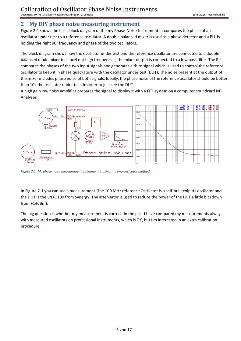
2 My DIY phase noise measuring instrument Figure 2-1 shows the basic block diagram of the my Phase-Noise-Instrument. It compares the phase of an
oscillator under test to a reference oscillator. A double balanced mixer is used as a phase detector and a PLL is
holding the right 90° frequency and phase of the two oscillators.
The block diagram shows how the oscillator under test and the reference oscillator are connected to a double
balanced diode mixer to cancel out high frequencies, the mixer output is connected to a low pass filter. The PLL
compares the phases of the two input signals and generates a third signal which is used to control the reference
oscillator to keep it in phase quadrature with the oscillator under test (DUT). The noise present at the output of
the mixer includes phase noise of both signals. Ideally, the phase noise of the reference oscillator should be better
than 10x the oscillator under test, in order to just see the DUT.
A high gain low noise amplifier prepares the signal to display it with a FFT-system on a computer soundcard NF-
Analyser.
Figure 2-1: My phase noise measurement instrument is using the two-oscillator method.
In Figure 2-1 you can see a measurement. The 100 MHz reference Oscillator is a self-built colpitts oscillator and
the DUT is the LNXO100 from Synergy. The attenuator is used to reduce the power of the DUT a little bit (down
from +14dBm).
The big question is whether my measurement is correct. In the past I have compared my measurements always
with measured oscillators on professional instruments, which is OK, but I’m interested in an extra calibration
procedure.
Calibration of Oscillator Phase Noise Instruments Document: DK7JB_OscillatorPhaseNoiseCalibration_010e.docx Jörn DK7JB [email protected]
6 von 17
3 Calibration procedure – Version I
3.1 Calibration procedure
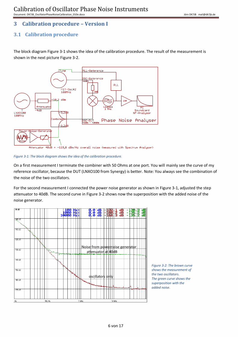
The block diagram Figure 3-1 shows the idea of the calibration procedure. The result of the measurement is
shown in the next picture Figure 3-2.
Figure 3-1: The block diagram shows the idea of the calibration procedure.
On a first measurement I terminate the combiner with 50 Ohms at one port. You will mainly see the curve of my
reference oscillator, because the DUT (LNXO100 from Synergy) is better. Note: You always see the combination of
the noise of the two oscillators.
For the second measurement I connected the power noise generator as shown in Figure 3-1, adjusted the step
attenuator to 40dB. The second curve in Figure 3-2 shows now the superposition with the added noise of the
noise generator.
Figure 3-2: The brown curve shows the measurement of the two oscillators. The green curve shows the superposition with the added noise.
Calibration of Oscillator Phase Noise Instruments Document: DK7JB_OscillatorPhaseNoiseCalibration_010e.docx Jörn DK7JB [email protected]
7 von 17
3.2 Calculation - overview Here you find the calculation steps. Please check whether I have made a mistake and have perhaps overlooked a
correction factor or something else.
A 40dB attenuator is used together with a power noise generator.
Power of the oscillator behind the combiner:
+10,2dBm (oscillator LNXO100 behind the 4dB pad)
- 3,2dB (S21-Coupler)
+ 7,0dBm
Power spectrum density of the noise generator (DSB-Phase Noise):4
- 119,8dBm/Hz noise generator with 40dB attenuation (measured with spectrum analyser)
- 3,2dBm/Hz S21-coupler
- 3,0dB (Part of the phase noise of the overall noise)5
- 126,0dBm/Hz In relation to 0dBm
Power spectrum density of the noise generator (SSB-Phase Noise):
- 126,0dBm/Hz In relation to 0dBm
- 3,0dB (SSB correction)
- 129,0dBm/Hz
In relation to the power of the oscillator of +7,0dBm:6
- 129,0dBm/Hz
- 7,0dBm/Hz power of the oscillator
-136,0dBc/Hz (SSB-Phase Noise)
In the phase noise measurement system the additional noise line is expected for Singlesidband Phase Noise at -
136.0dBc/Hz far of the carrier.
My measurement shows -135,2dBc/Hz @10kHz. The difference to the calculated -136dBc/Hz is less than 1dB.
The small difference indicates that my measurement is already pretty precise and that only minor corrections are
necessary. This makes me happy.
This document does not describe any measurement errors or precision of the used instruments. I always try to
measure as precise as it is possible with hobbyist equipment. All my equipment was sanity checked and where
possible cross checked. Although I calculate with 1/10th of a dB, I do know that no spectrum analyzer is as
precise as 1/10th of a dB.
4 All spectrum analysers only measure both noise side bands of a noise generator. Phase noise measurement systems measure single side band noise. Therefore a correction of 3dB is due to cope with SA-measurements of noise generator. 5 The noise generator delivers phase + amplitude noise in a 50/50 proportion. Therefore the phase noise is 3dB smaller than total noise. Total noise (-174dBm/Hz)= phase noise (-177dBm/Hz) + amplitude noise (-177dBm/Hz). 6 The phase noise system shows power spectral density in relation to the oscillator carrier, in dBc/Hz.
Calibration of Oscillator Phase Noise Instruments Document: DK7JB_OscillatorPhaseNoiseCalibration_010e.docx Jörn DK7JB [email protected]
8 von 17
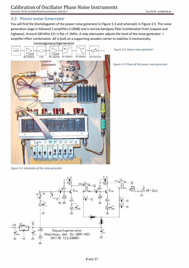
3.3 Power noise-Generator You will find the blockdiagamm of the power noise generator in Figure 3-3 and schematic in Figure 3-5. The noise
generation stage is followed 2 amplifiers (+39dB) and a narrow bandpass filter (combination from lowpass and
highpass). Around 100 MHz S21 is flat +/-1MHz. A step attenuator adjusts the level of the noise generator +
amplifier+filter combination. All is built on a supporting wooden carrier to stabilize it mechanically.
Figure 3-4: Photo of the power noise generator
Figure 3-5: Schematic of the noise generator
Figure 3-3: Power noise generator
Calibration of Oscillator Phase Noise Instruments Document: DK7JB_OscillatorPhaseNoiseCalibration_010e.docx Jörn DK7JB [email protected]
9 von 17
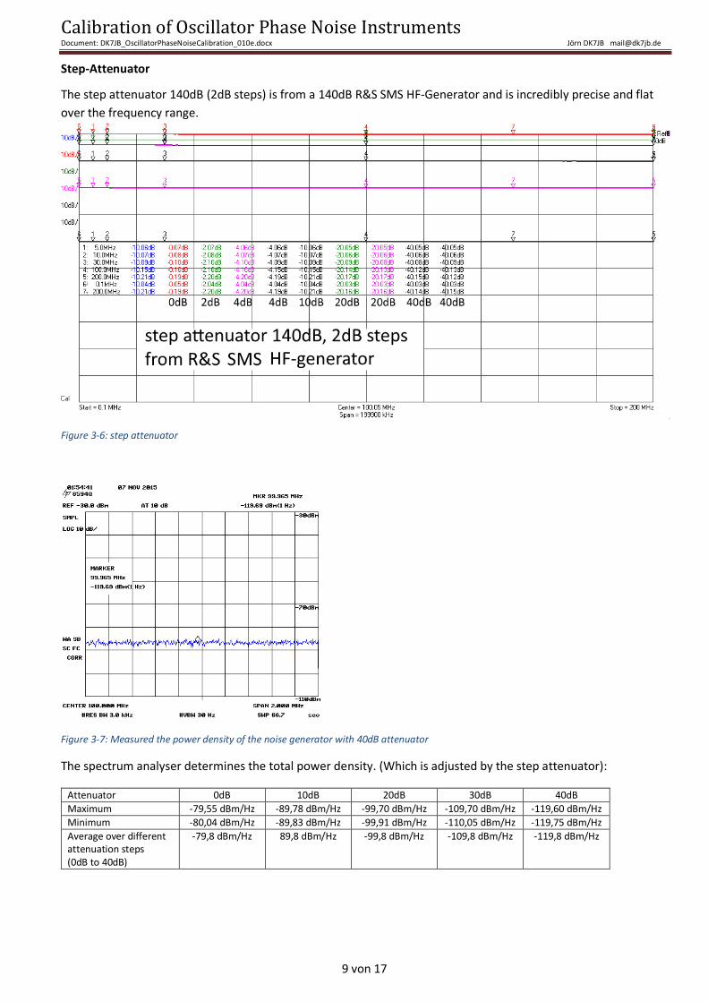
Step-Attenuator
The step attenuator 140dB (2dB steps) is from a 140dB R&S SMS HF-Generator and is incredibly precise and flat
over the frequency range.
Figure 3-6: step attenuator
Figure 3-7: Measured the power density of the noise generator with 40dB attenuator
The spectrum analyser determines the total power density. (Which is adjusted by the step attenuator):
Attenuator 0dB 10dB 20dB 30dB 40dB
Maximum -79,55 dBm/Hz -89,78 dBm/Hz -99,70 dBm/Hz -109,70 dBm/Hz -119,60 dBm/Hz
Minimum -80,04 dBm/Hz -89,83 dBm/Hz -99,91 dBm/Hz -110,05 dBm/Hz -119,75 dBm/Hz
Average over different attenuation steps (0dB to 40dB)
-79,8 dBm/Hz 89,8 dBm/Hz -99,8 dBm/Hz -109,8 dBm/Hz -119,8 dBm/Hz
Calibration of Oscillator Phase Noise Instruments Document: DK7JB_OscillatorPhaseNoiseCalibration_010e.docx Jörn DK7JB [email protected]
10 von 17
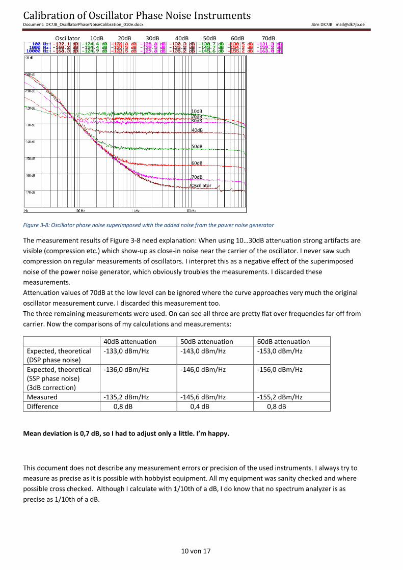
Figure 3-8: Oscillator phase noise superimposed with the added noise from the power noise generator
The measurement results of Figure 3-8 need explanation: When using 10…30dB attenuation strong artifacts are
visible (compression etc.) which show-up as close-in noise near the carrier of the oscillator. I never saw such
compression on regular measurements of oscillators. I interpret this as a negative effect of the superimposed
noise of the power noise generator, which obviously troubles the measurements. I discarded these
measurements.
Attenuation values of 70dB at the low level can be ignored where the curve approaches very much the original
oscillator measurement curve. I discarded this measurement too.
The three remaining measurements were used. On can see all three are pretty flat over frequencies far off from
carrier. Now the comparisons of my calculations and measurements:
40dB attenuation 50dB attenuation 60dB attenuation
Expected, theoretical (DSP phase noise)
-133,0 dBm/Hz -143,0 dBm/Hz -153,0 dBm/Hz
Expected, theoretical (SSP phase noise) (3dB correction)
-136,0 dBm/Hz -146,0 dBm/Hz -156,0 dBm/Hz
Measured -135,2 dBm/Hz -145,6 dBm/Hz -155,2 dBm/Hz
Difference 0,8 dB 0,4 dB 0,8 dB
Mean deviation is 0,7 dB, so I had to adjust only a little. I’m happy.
This document does not describe any measurement errors or precision of the used instruments. I always try to
measure as precise as it is possible with hobbyist equipment. All my equipment was sanity checked and where
possible cross checked. Although I calculate with 1/10th of a dB, I do know that no spectrum analyzer is as
precise as 1/10th of a dB.
Calibration of Oscillator Phase Noise Instruments Document: DK7JB_OscillatorPhaseNoiseCalibration_010e.docx Jörn DK7JB [email protected]
11 von 17
3.4 The Spectrum Analyser For my measurements I used HP8594Q + Options 004 (Oven), 190 (QAM DEMOD rev 970522), 195 (FEC DECODE),
041 (GPIB+PARALLEL), 8594Q #171, Firmware rev 96.12.16
All devices were warmed up and coaxes + DC-block were calibrated-in with Spectrum Analyser’s self-calibration
routine.
Further functions & information: To determine the power noise density the Spectrum Analyser internal function
„MK NOISE“ was used. The user manual notes:
MK NOISE reads out the average noise level, referenced to a 1 Hz noise power bandwidth, at the marker position. If no marker is present, a marker appears at the center of the screen. The root-mean-square noise level, normalized to a 1 Hz noise power bandwidth, is read out. The sample detector is activated. Front-Panel Key Access: (MCR FCTN)
3.5 My program settings Programm:
Sample Length: 131072 ADC Sample Rate: 192 ksps / 24 bit
Offset with E-MU 0204: -76,0 dB Window Type: Flat Top
Verwendete Geräte:
Combiner (ZFSC-2-1)
HP8594Q:
#RES_BW=3,0kHz #VBW=30Hz Front-Panel Key Access: (MCR FCTN)- MK NOISE
REF=-30dBm AT 10dB Center 100MHz SPAN=2MHz
Calibration of Oscillator Phase Noise Instruments Document: DK7JB_OscillatorPhaseNoiseCalibration_010e.docx Jörn DK7JB [email protected]
12 von 17
4 Ergänzende Erklärungen zum Messverfahren Die folgenden Beispiele sollen das Messverfahren leichter verständlich machen. I will translate it later.
Wir müssen zwischen der Messung mit dem Spektrum Analyser und der Messung mit dem
Phasenrauschmessplatz unterscheiden, wenn man das Messverfahren verstehen möchte. Der folgende Versuch
soll uns helfen.
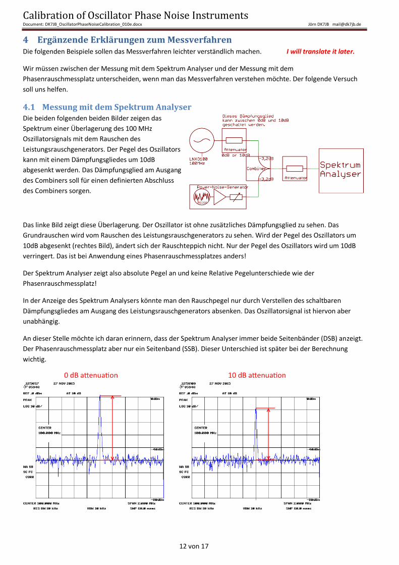
4.1 Messung mit dem Spektrum Analyser Die beiden folgenden beiden Bilder zeigen das
Spektrum einer Überlagerung des 100 MHz
Oszillatorsignals mit dem Rauschen des
Leistungsrauschgenerators. Der Pegel des Oszillators
kann mit einem Dämpfungsgliedes um 10dB
abgesenkt werden. Das Dämpfungsglied am Ausgang
des Combiners soll für einen definierten Abschluss
des Combiners sorgen.
Das linke Bild zeigt diese Überlagerung. Der Oszillator ist ohne zusätzliches Dämpfungsglied zu sehen. Das
Grundrauschen wird vom Rauschen des Leistungsrauschgenerators zu sehen. Wird der Pegel des Oszillators um
10dB abgesenkt (rechtes Bild), ändert sich der Rauschteppich nicht. Nur der Pegel des Oszillators wird um 10dB
verringert. Das ist bei Anwendung eines Phasenrauschmessplatzes anders!
Der Spektrum Analyser zeigt also absolute Pegel an und keine Relative Pegelunterschiede wie der
Phasenrauschmessplatz!
In der Anzeige des Spektrum Analysers könnte man den Rauschpegel nur durch Verstellen des schaltbaren
Dämpfungsgliedes am Ausgang des Leistungsrauschgenerators absenken. Das Oszillatorsignal ist hiervon aber
unabhängig.
An dieser Stelle möchte ich daran erinnern, dass der Spektrum Analyser immer beide Seitenbänder (DSB) anzeigt.
Der Phasenrauschmessplatz aber nur ein Seitenband (SSB). Dieser Unterschied ist später bei der Berechnung
wichtig.
Calibration of Oscillator Phase Noise Instruments Document: DK7JB_OscillatorPhaseNoiseCalibration_010e.docx Jörn DK7JB [email protected]
13 von 17
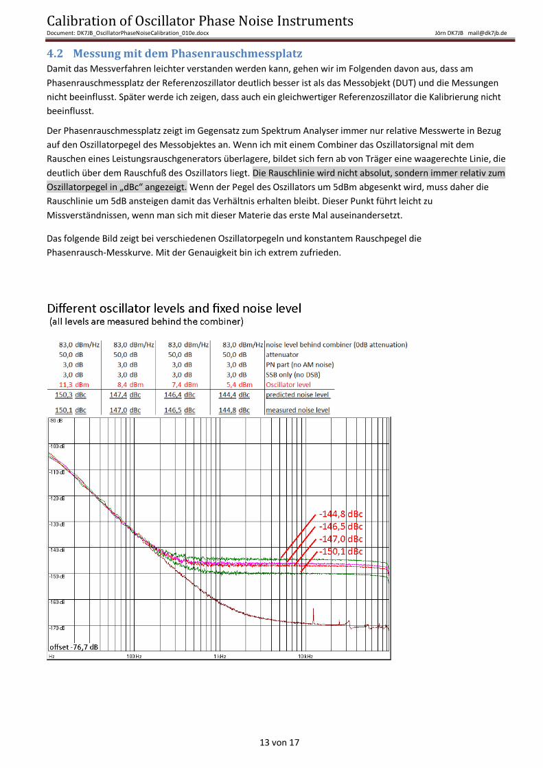
4.2 Messung mit dem Phasenrauschmessplatz Damit das Messverfahren leichter verstanden werden kann, gehen wir im Folgenden davon aus, dass am
Phasenrauschmessplatz der Referenzoszillator deutlich besser ist als das Messobjekt (DUT) und die Messungen
nicht beeinflusst. Später werde ich zeigen, dass auch ein gleichwertiger Referenzoszillator die Kalibrierung nicht
beeinflusst.
Der Phasenrauschmessplatz zeigt im Gegensatz zum Spektrum Analyser immer nur relative Messwerte in Bezug
auf den Oszillatorpegel des Messobjektes an. Wenn ich mit einem Combiner das Oszillatorsignal mit dem
Rauschen eines Leistungsrauschgenerators überlagere, bildet sich fern ab von Träger eine waagerechte Linie, die
deutlich über dem Rauschfuß des Oszillators liegt. Die Rauschlinie wird nicht absolut, sondern immer relativ zum
Oszillatorpegel in „dBc“ angezeigt. Wenn der Pegel des Oszillators um 5dBm abgesenkt wird, muss daher die
Rauschlinie um 5dB ansteigen damit das Verhältnis erhalten bleibt. Dieser Punkt führt leicht zu
Missverständnissen, wenn man sich mit dieser Materie das erste Mal auseinandersetzt.
Das folgende Bild zeigt bei verschiedenen Oszillatorpegeln und konstantem Rauschpegel die
Phasenrausch-Messkurve. Mit der Genauigkeit bin ich extrem zufrieden.
Calibration of Oscillator Phase Noise Instruments Document: DK7JB_OscillatorPhaseNoiseCalibration_010e.docx Jörn DK7JB [email protected]
14 von 17
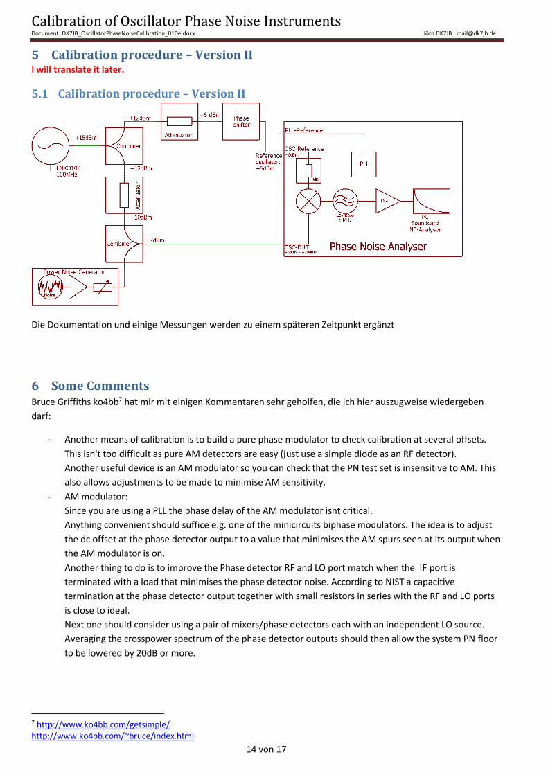
5 Calibration procedure – Version II I will translate it later.
5.1 Calibration procedure – Version II
Die Dokumentation und einige Messungen werden zu einem späteren Zeitpunkt ergänzt
6 Some Comments Bruce Griffiths ko4bb7 hat mir mit einigen Kommentaren sehr geholfen, die ich hier auszugweise wiedergeben
darf:
- Another means of calibration is to build a pure phase modulator to check calibration at several offsets.
This isn't too difficult as pure AM detectors are easy (just use a simple diode as an RF detector).
Another useful device is an AM modulator so you can check that the PN test set is insensitive to AM. This
also allows adjustments to be made to minimise AM sensitivity.
- AM modulator:
Since you are using a PLL the phase delay of the AM modulator isnt critical.
Anything convenient should suffice e.g. one of the minicircuits biphase modulators. The idea is to adjust
the dc offset at the phase detector output to a value that minimises the AM spurs seen at its output when
the AM modulator is on.
Another thing to do is to improve the Phase detector RF and LO port match when the IF port is
terminated with a load that minimises the phase detector noise. According to NIST a capacitive
termination at the phase detector output together with small resistors in series with the RF and LO ports
is close to ideal.
Next one should consider using a pair of mixers/phase detectors each with an independent LO source.
Averaging the crosspower spectrum of the phase detector outputs should then allow the system PN floor
to be lowered by 20dB or more.
7 http://www.ko4bb.com/getsimple/ http://www.ko4bb.com/~bruce/index.html
Calibration of Oscillator Phase Noise Instruments Document: DK7JB_OscillatorPhaseNoiseCalibration_010e.docx Jörn DK7JB [email protected]
15 von 17
7 Noch offene Baustellen
Das Gerät soll noch in ein Gehäuse gebaut werden.
Hierbei soll ein zugekaufter Leistungsrauschgenerator, selbstgebaute Verstärker und selbstgebaute Bandpässe
verwendet werden.
Noch ungelöstes Problem Für das Dämpfungsglied werden 15V benötigt und für die Verstärker 12V. Ein Akku
liefert 12V und der Phasenrauschmessplatz 12-12,4V. (evt. DC/DC Wandler 12V/15V verwenden).
Geregelte Spannungsversorgung für die Verstärker verwenden um eine konstant Verstärkung zu erzielen.
Zum Entkoppeln Übertrager und Gleichtaktdrosseln verwenden.
Calibration of Oscillator Phase Noise Instruments Document: DK7JB_OscillatorPhaseNoiseCalibration_010e.docx Jörn DK7JB [email protected]
16 von 17
8 Literature
8.1 Literature about improving the phase noise measurement I’ m sorry but currently I cannot interpret all sources correctly as the description are not detailed enough for me.
TCI-ANT - Papers and Application Note: http://tci-ant.com/improvingaccuracyampa.pdf
[NIST 1993] „Secondary standard for PM and AM noise at 5, 10, and 100 MHz”; Fred L. Walls; NIST
http://www.nist.gov/calibrations/upload/ieee42.pdf
[NIST 2012] “Calibration Uncertainty for the NIST PM/AM Noise Standards“; NIST Special Publication 250-90
http://www.nist.gov/calibrations/upload/SP250-90Final-102412-pdf-2.pdf
[Roberts 2010] “Implementing and Validating State-of-the-Art Phase Noise Measurement”; Paul C. A. Roberts,
Fluke Calibration; 2010 NCSL International Workshop and Symposium
8.2 Literature about phase noise measurement in general This list is just a small selection:
[Janásek 2015]: Design of ultra low noise amplifiers; Janásek, Vojtěch
http://www.janascard.cz/PDF/Design%20of%20ultra%20low%20noise%20amplifiers.pdf
[Kaa 2013] Information about my phase noise instrument: Ein Phasenrauschmessplatz im Eigenbau, Bernd Kaa
DG4RBF, Tagungsband zur 58. Weinheimer UKW Tagung 2013, Seiten 11.1 bis 11.12
[Wenzel] Good literature from Wenzel Associates, Inc:
http://www.wenzel.com/documents/measuringphasenoise.htm
http://www.wenzel.com/documents/hints.htm
http://www.techlib.com/files/lowamp.pdf
8.3 Good Literature “Good Practice Guide to Phase Noise Measurement“; David Owen;
jmfriedt.sequanux.org/phase_digital/mgpg68.pdf
“Choosing a Phase Noise Measurement Technique Concepts and Implementation”; Terry Decker and Bob Temple;
http://jmfriedt.sequanux.org/phase_digital/mgpg68.pdf
“Phase Noise and AM Noise Measurements in the Frequency Domain”; A.L. Lance;
http://tf.nist.gov/general/tn1337/Tn190.pdf
“Phase Noise Measurements and its Limitations”; Ulrich L. Rohde, Ajay K. Poddar, Anisha M. Apte,
Synergy Microwave Corporation, NJ, USA; http://synergymwave.com/articles/2013/04/full_article.pdf
Calibration of Oscillator Phase Noise Instruments Document: DK7JB_OscillatorPhaseNoiseCalibration_010e.docx Jörn DK7JB [email protected]
17 von 17
“Implementing and Validating State-of-the-Art Phase Noise Measurement”; Paul C. A. Roberts, Fluke Calibration;
http://www.ncsli.org/i/c/TransactionLib/2E-1%20Roberts.pdf
Recommended


![Noise calibration, delay coherence and SNR walls for ...sahai/Presentations/DelayCoherenceDySpAN08.pdfNoise calibration: cyclostationary feature detection AGC calibration: Yb[n] =](https://img.pdfslide.us/doc/110x75/5edf89c8ad6a402d666ae0a3/noise-calibration-delay-coherence-and-snr-walls-for-sahaipresentationsdelaycoherencedyspan08pdf.jpg)