Calculation of ShieldingRequirements for PET/CT and
SPECT/CT
Jocelyn TowsonRoyal Prince Alfred Hospital
ANZSNM/ACPSEM Physics SIG SymposiumUniversity of Sydney, 8 December 2006
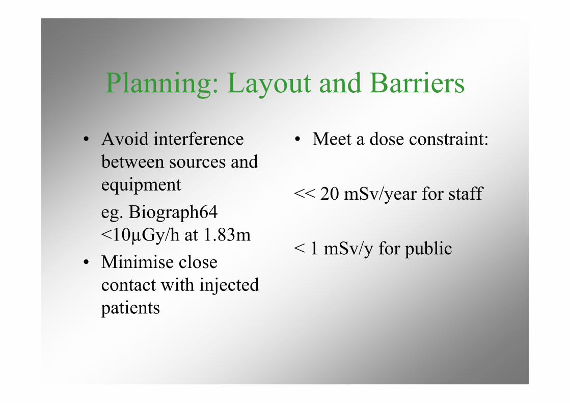
Planning: Layout and Barriers
• Avoid interferencebetween sources andequipmenteg. Biograph64<10µGy/h at 1.83m
• Minimise closecontact with injectedpatients
• Meet a dose constraint:
<< 20 mSv/year for staff
< 1 mSv/y for public
In general ….
• Walls of SPECT camera rooms with 2mmlead should be adequate for CT
• Walls of PET scanner rooms should also beadequate for CT
• Special requirements if adding CT will haveto be addressed eg. Barrier integrity, doorrebates, viewing windows
CT radiation• Much higher radiation output and workload
(mA-min per week) than other apparatus• High tube voltage and current• Beam is hardened by additional filtration• MSCT beam widths 40mm or more• High heat capacity - long runs possible• Primary beam confined to patient and
gantry
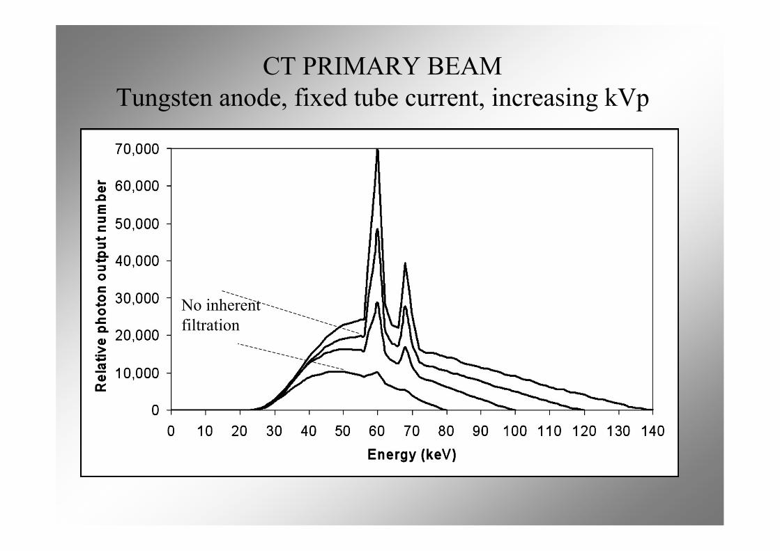
CT PRIMARY BEAMTungsten anode, fixed tube current, increasing kVp
No inherentfiltration
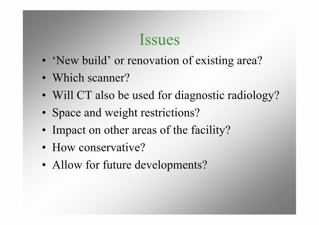
Issues• ‘New build’ or renovation of existing area?• Which scanner?• Will CT also be used for diagnostic radiology?• Space and weight restrictions?• Impact on other areas of the facility?• How conservative?• Allow for future developments?
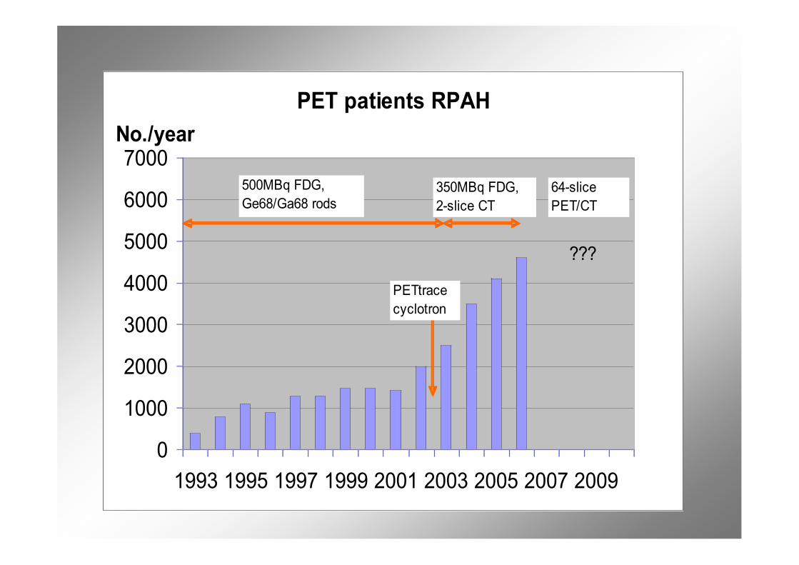
PET patients RPAH
0
1000
2000
3000
4000
5000
6000
7000
1993 1995 1997 1999 2001 2003 2005 2007 2009
No./year
500MBq FDG,
Ge68/Ga68 rods350MBq FDG,
2-slice CT
PETtrace
cyclotron
64-slice
PET/CT
???
RPAH PET Suite 2010
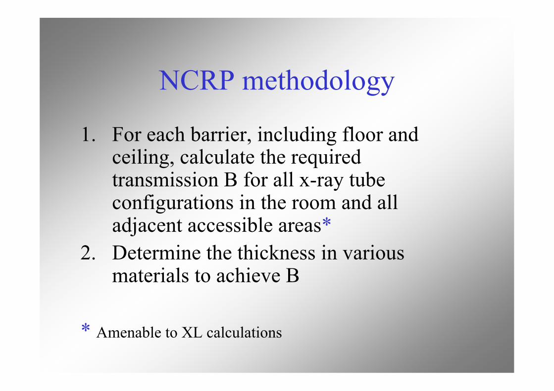
NCRP methodology
1. For each barrier, including floor andceiling, calculate the requiredtransmission B for all x-ray tubeconfigurations in the room and alladjacent accessible areas*
2. Determine the thickness in variousmaterials to achieve B
* Amenable to XL calculations
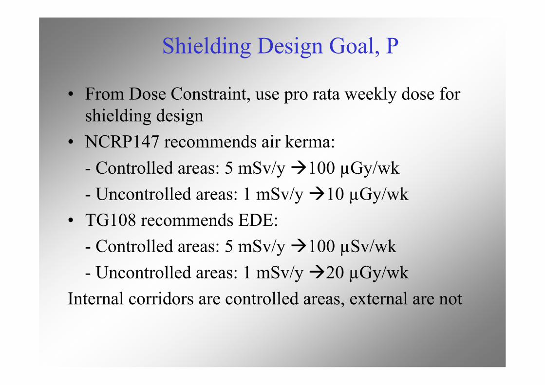
Shielding Design Goal, P
• From Dose Constraint, use pro rata weekly dose forshielding design
• NCRP147 recommends air kerma:- Controlled areas: 5 mSv/y 100 µGy/wk- Uncontrolled areas: 1 mSv/y 10 µGy/wk
• TG108 recommends EDE:- Controlled areas: 5 mSv/y 100 µSv/wk- Uncontrolled areas: 1 mSv/y 20 µGy/wk
Internal corridors are controlled areas, external are not
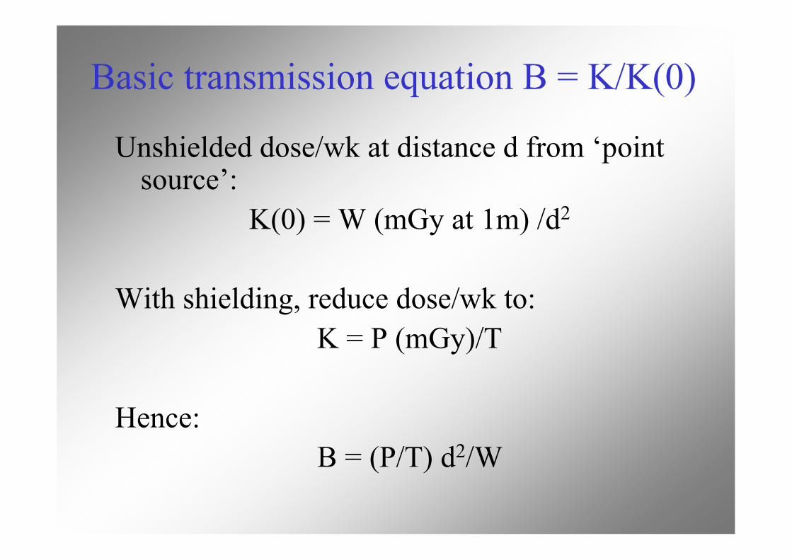
Basic transmission equation B = K/K(0)
Unshielded dose/wk at distance d from ‘pointsource’:
K(0) = W (mGy at 1m) /d2
With shielding, reduce dose/wk to:K = P (mGy)/T
Hence:B = (P/T) d2/W
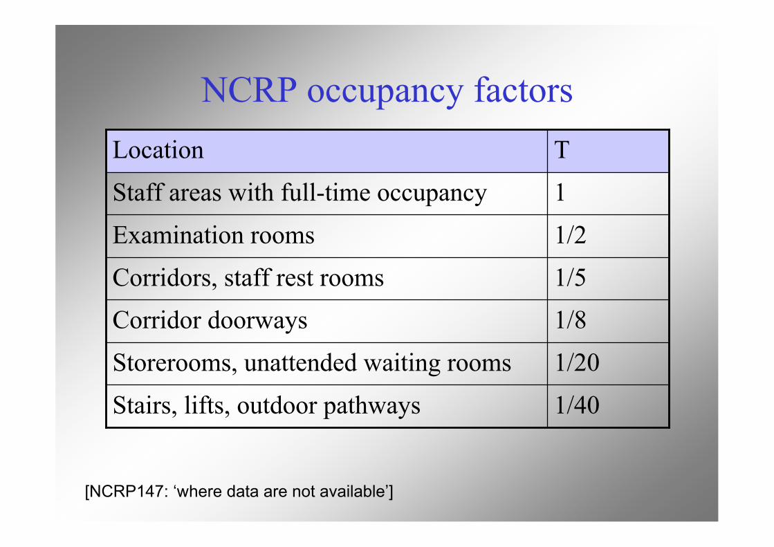
NCRP occupancy factors
1/40Stairs, lifts, outdoor pathways
1/20Storerooms, unattended waiting rooms
1/8Corridor doorways1/5Corridors, staff rest rooms
1/2Examination rooms
1Staff areas with full-time occupancy
TLocation
[NCRP147: ‘where data are not available’]
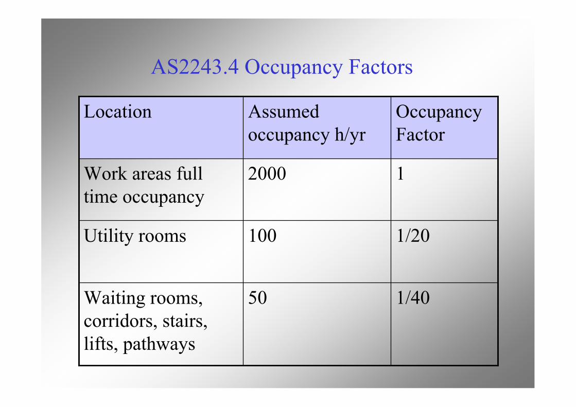
AS2243.4 Occupancy Factors
1/4050Waiting rooms,corridors, stairs,lifts, pathways
1/20100Utility rooms
12000Work areas fulltime occupancy
OccupancyFactor
Assumedoccupancy h/yr
Location
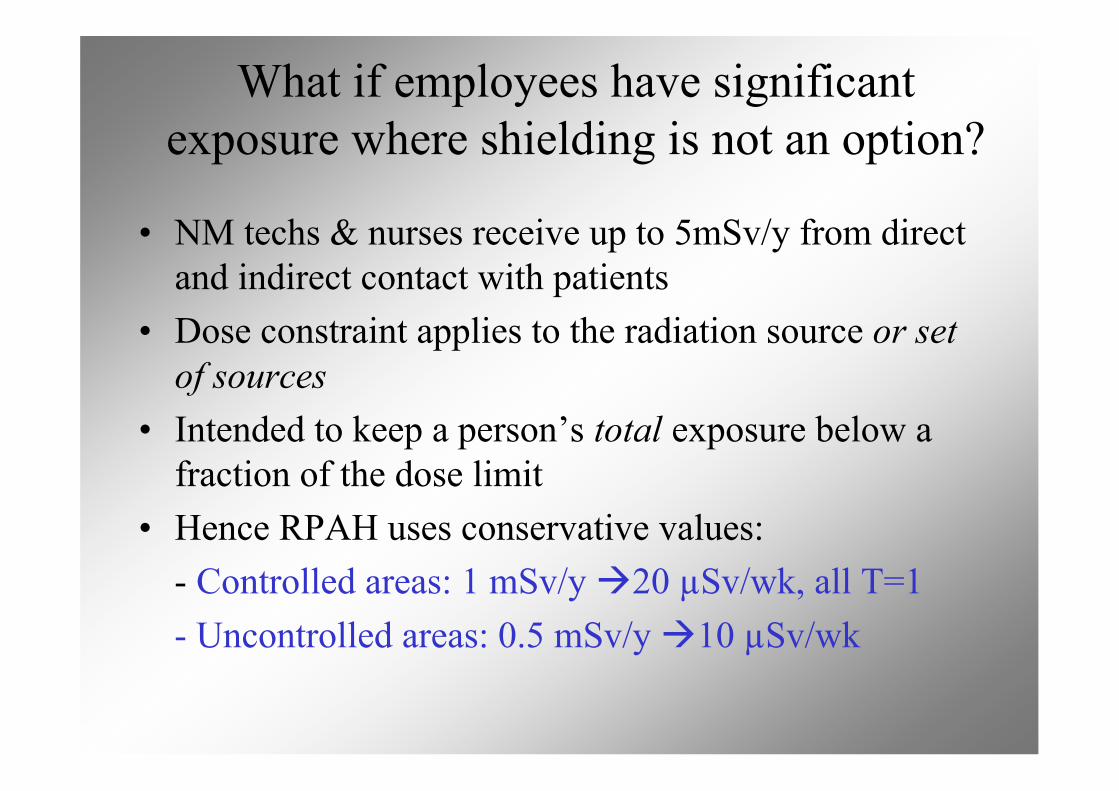
What if employees have significantexposure where shielding is not an option?
• NM techs & nurses receive up to 5mSv/y from directand indirect contact with patients
• Dose constraint applies to the radiation source or setof sources
• Intended to keep a person’s total exposure below afraction of the dose limit
• Hence RPAH uses conservative values:- Controlled areas: 1 mSv/y 20 µSv/wk, all T=1- Uncontrolled areas: 0.5 mSv/y 10 µSv/wk
From AAPM Task Group 108: PET and PET/CT Shielding
Distance for use in shielding calculations
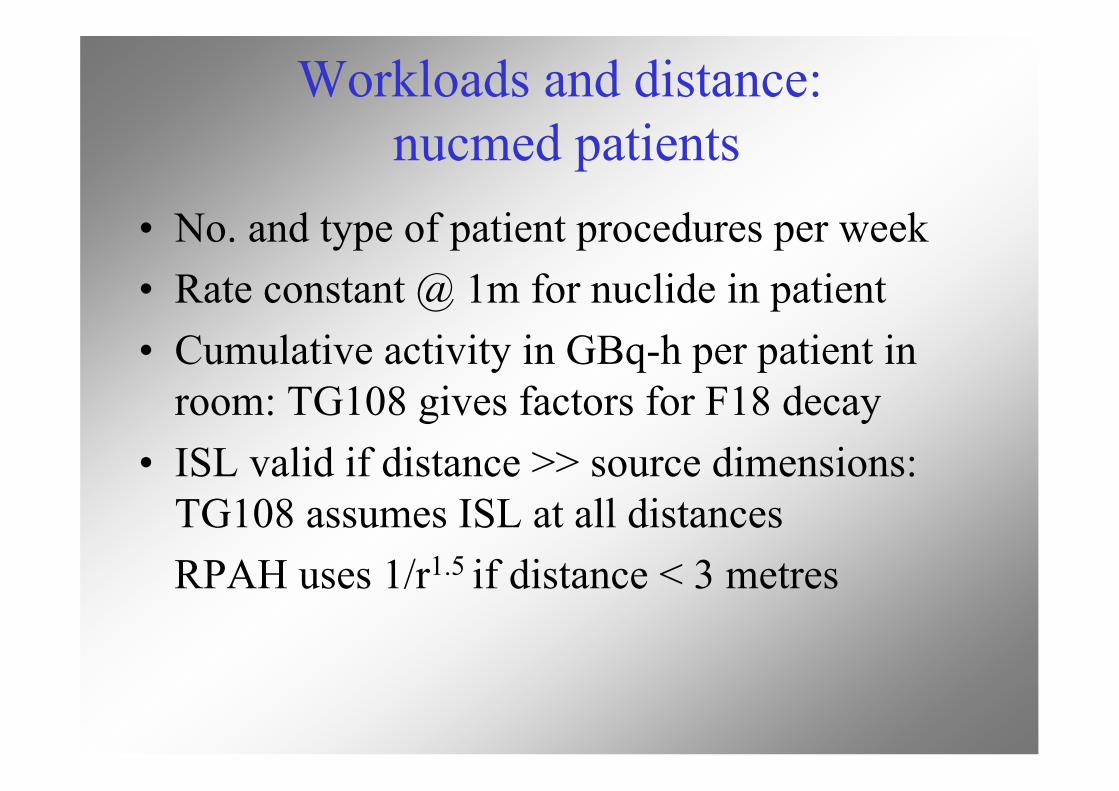
Workloads and distance: nucmed patients
• No. and type of patient procedures per week• Rate constant @ 1m for nuclide in patient• Cumulative activity in GBq-h per patient in
room: TG108 gives factors for F18 decay• ISL valid if distance >> source dimensions:
TG108 assumes ISL at all distancesRPAH uses 1/r1.5 if distance < 3 metres
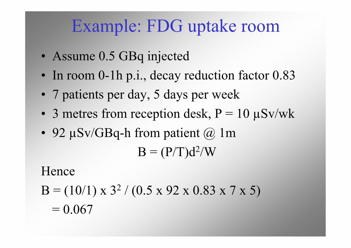
Example: FDG uptake room• Assume 0.5 GBq injected• In room 0-1h p.i., decay reduction factor 0.83• 7 patients per day, 5 days per week• 3 metres from reception desk, P = 10 µSv/wk• 92 µSv/GBq-h from patient @ 1m
B = (P/T)d2/WHenceB = (10/1) x 32 / (0.5 x 92 x 0.83 x 7 x 5)
= 0.067
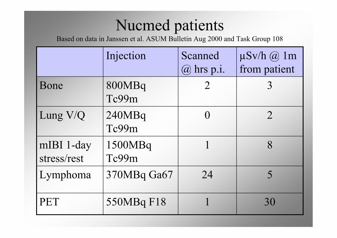
Nucmed patientsBased on data in Janssen et al. ASUM Bulletin Aug 2000 and Task Group 108
301550MBq F18PET
524370MBq Ga67Lymphoma
811500MBqTc99m
mIBI 1-daystress/rest
20240MBqTc99m
Lung V/Q
32800MBqTc99m
Bone
µSv/h @ 1mfrom patient
Scanned@ hrs p.i.
Injection
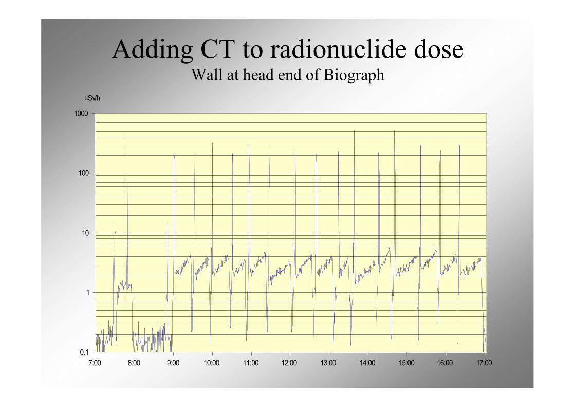
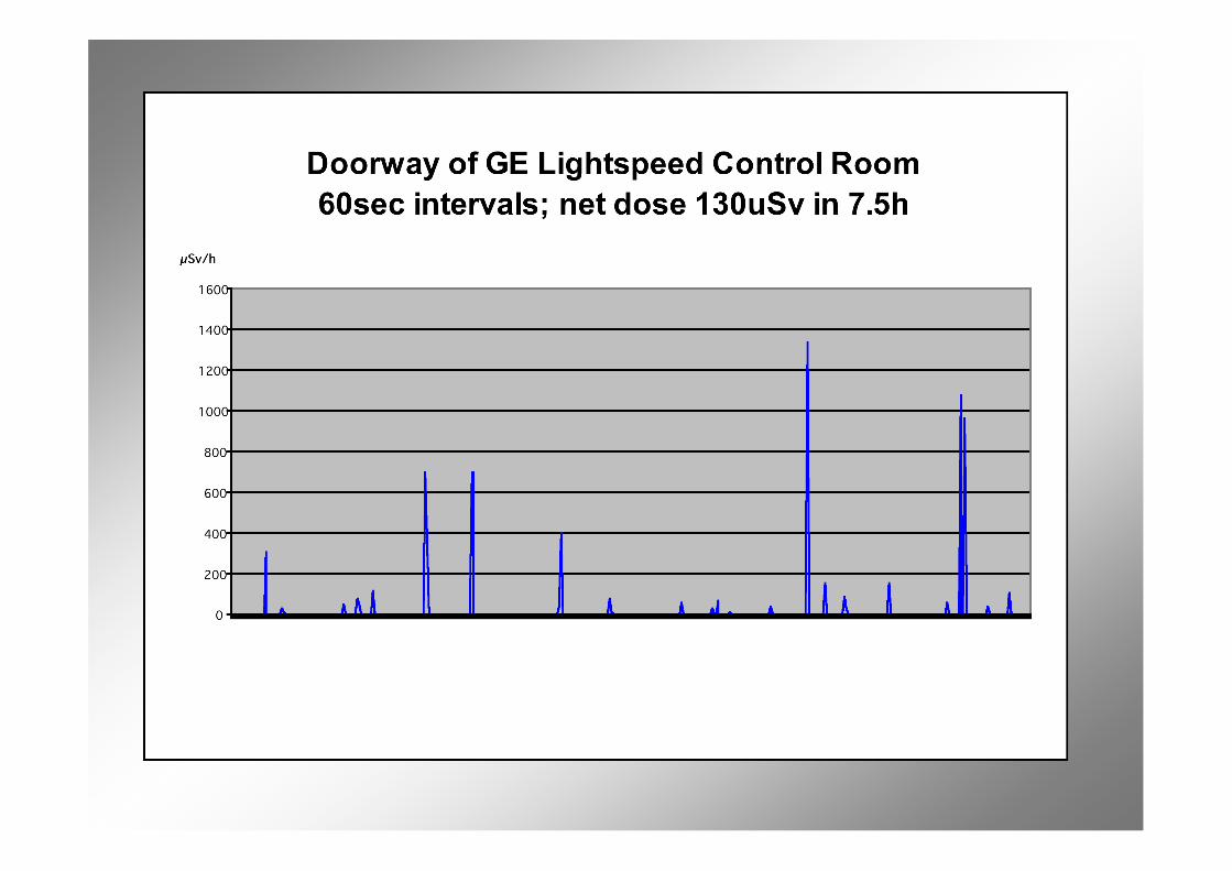
0.1
1
10
100
1000
7:00 8:00 9:00 10:00 11:00 12:00 13:00 14:00 15:00 16:00 17:00
µSv/h
Adding CT to radionuclide doseWall at head end of Biograph
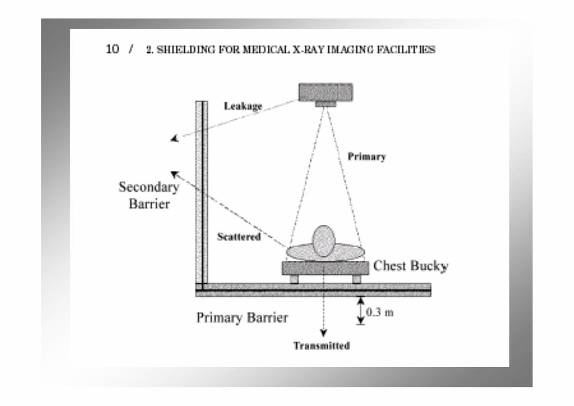
CT secondary radiation: leakage
• Beam is hardened by tube housing• Effective energy is close to kVp• Anisotropic• Regulatory limit on air kerma rate of
0.876 mGy/h (0.1R/h exposure rate)at 1meter, for continuous operation atmaximum kV and maximum mA atthat potential
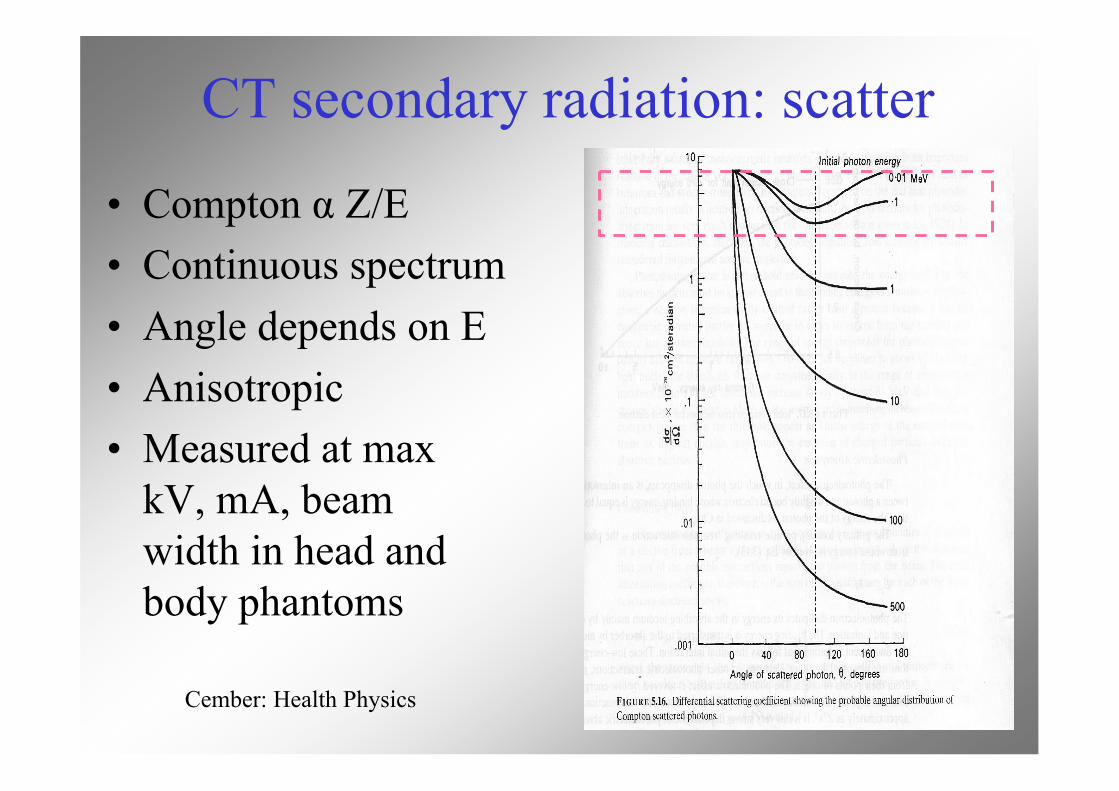
CT secondary radiation: scatter
• Compton α Z/E• Continuous spectrum• Angle depends on E• Anisotropic• Measured at max
kV, mA, beamwidth in head andbody phantoms
Cember: Health Physics
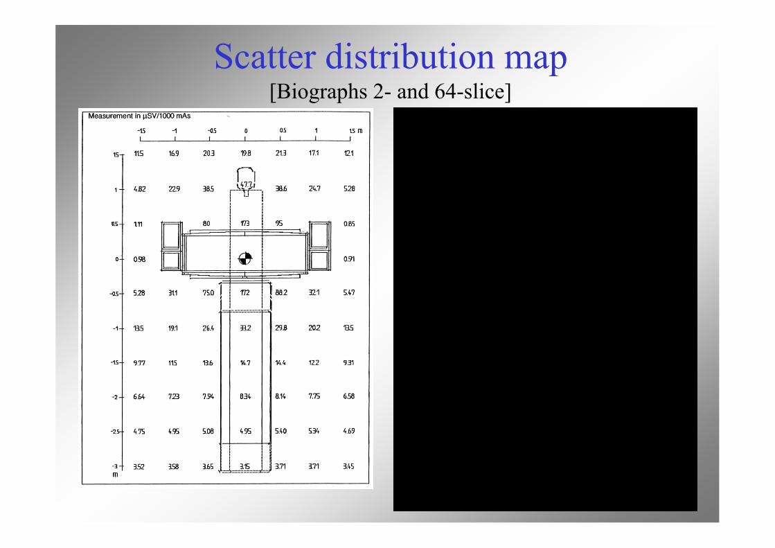
Scatter distribution map[Biographs 2- and 64-slice]
CT workload, distance
NCRP147:• Air kerma rate @ 1m per patient for head
and body scans• Assume isotropic• Correct K values with ISL• Scale up for no. of procedures per week
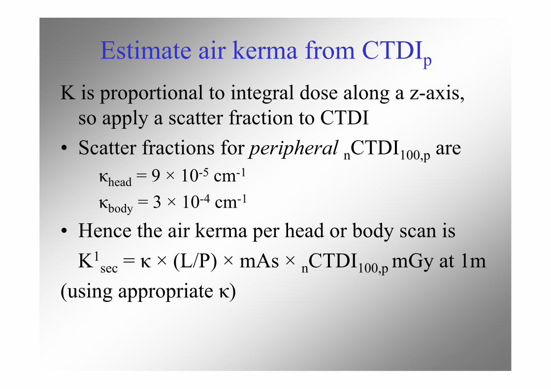
Estimate air kerma from CTDIp
K is proportional to integral dose along a z-axis,so apply a scatter fraction to CTDI
• Scatter fractions for peripheral nCTDI100,p areκhead = 9 × 10⁻⁵ cm-1
κbody = 3 × 10⁻⁴ cm-1
• Hence the air kerma per head or body scan isK1
sec = κ × (L/P) × mAs × nCTDI100,p mGy at 1m(using appropriate κ)
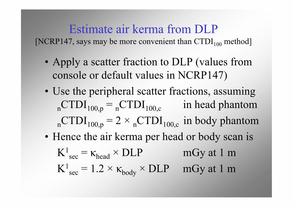
Estimate air kerma from DLP[NCRP147, says may be more convenient than CTDI100 method]
• Apply a scatter fraction to DLP (values fromconsole or default values in NCRP147)
• Use the peripheral scatter fractions, assumingnCTDI100,p = nCTDI100,c in head phantom
nCTDI100,p = 2 × nCTDI100,c in body phantom• Hence the air kerma per head or body scan is
K1sec = κhead × DLP mGy at 1 m
K1sec = 1.2 × κbody × DLP mGy at 1 m
Estimate air kermafrom scanner information
K is proportional to Workload (mA-min)• Use isotropic model based on manufacturer’s
specification for air kerma at 1m• Use isodose contours or scatter maps of µGy
per mAs for maximum kV, mA and beamwidth on head or body phantom
BarriersBarriers
From Doug From Doug SimpkinSimpkin, AAPM 2002, AAPM 2002
• No finite barrier thickness willcompletely eliminate theradiation dose outside adiagnostic x-ray room
Typical x-ray tech upon hearingthat he/she’s still getting somedose in the control booth
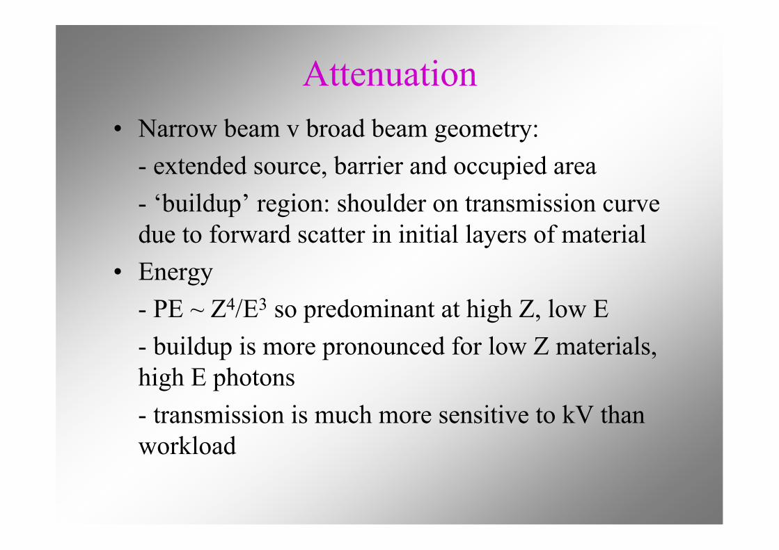
Attenuation• Narrow beam v broad beam geometry:
- extended source, barrier and occupied area- ‘buildup’ region: shoulder on transmission curvedue to forward scatter in initial layers of material
• Energy- PE ~ Z4/E3 so predominant at high Z, low E- buildup is more pronounced for low Z materials,high E photons- transmission is much more sensitive to kV thanworkload
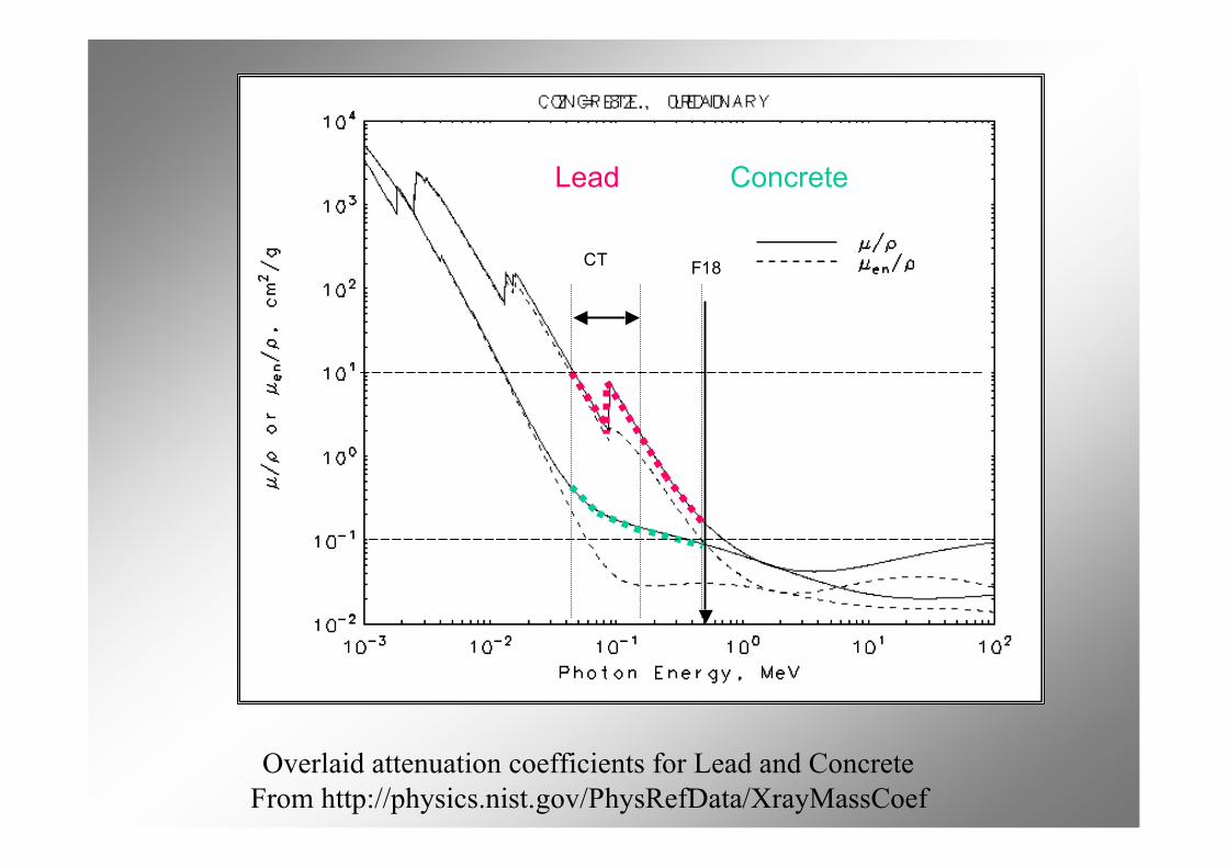
Overlaid attenuation coefficients for Lead and ConcreteFrom http://physics.nist.gov/PhysRefData/XrayMassCoef
Lead Concrete
F18CT
Estimating thickness withradionuclide coefficients
• Narrow beam: published HVL, TVL orattenuation coefficients (µ or µ/ρ)
• Broad beam:- published HVL, TVL coefficients- Buildup method with narrow beam µ
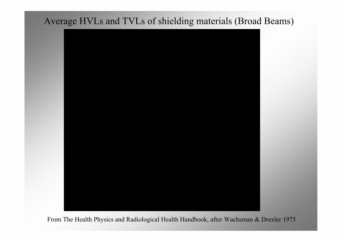
Average HVLs and TVLs of shielding materials (Broad Beams)
From The Health Physics and Radiological Health Handbook, after Wachsman & Drexler 1975
Estimating thickness from MCmodeling / Archer fitting parameters• Suitable for broad beam geometry, heterogenous
beam, any material• Archer proposed an empirical expression with 3
parameters, based on measured transmission of anx-ray beam at various thicknesses
• Parameters are fitted to MC data• Curves and parameters for CT are given in
NCRP147 and for 511keV in TG108
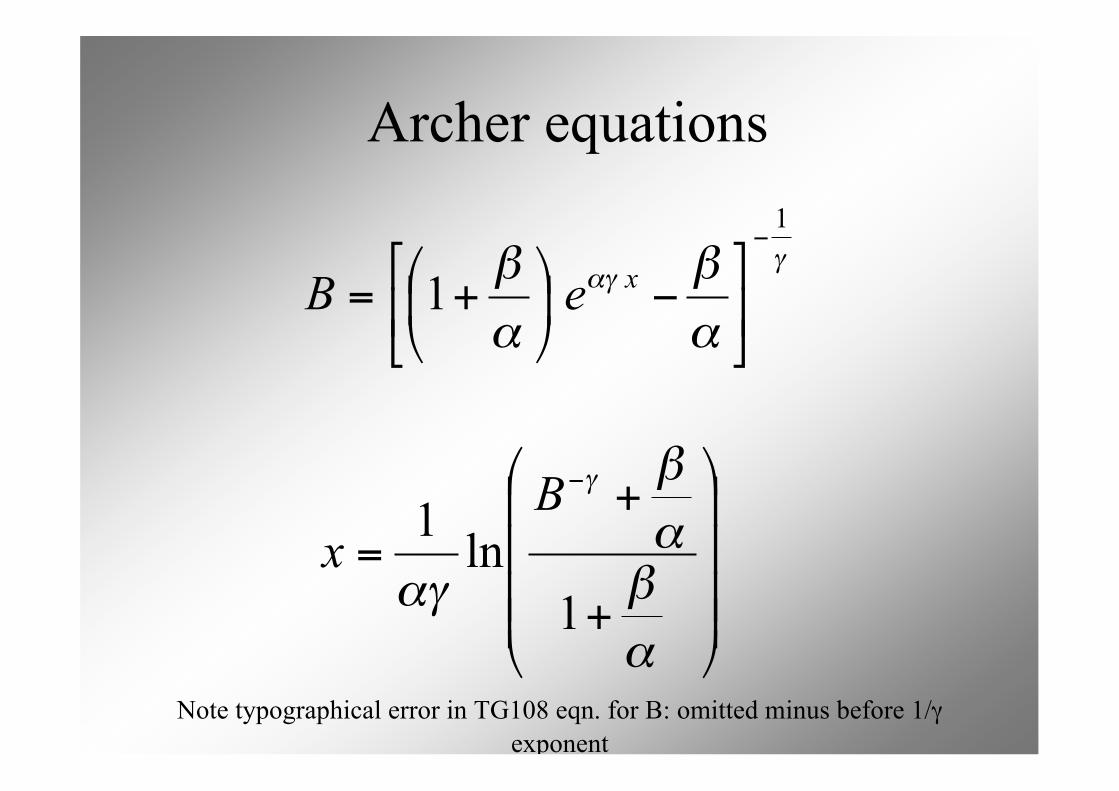
Archer equations
!"!
"
#
"
#1
1
$
%&
'()
*$+
,
-./
0+=
xeB
!!!!
"
#
$$$$
%
&
+
+
=
'
(
)(
)
(*
*
1
ln1
B
x
Note typographical error in TG108 eqn. for B: omitted minus before 1/γexponent
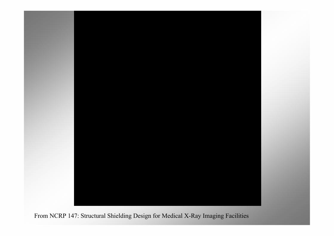
From NCRP 147: Structural Shielding Design for Medical X-Ray Imaging Facilities
From NCRP 147: Structural Shielding Design for Medical X-Ray Imaging Facilities
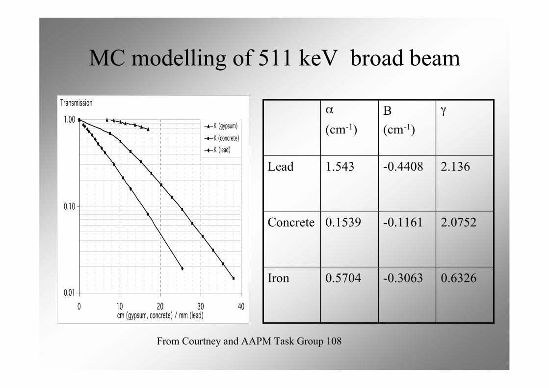
MC modelling of 511 keV broad beam
0.01
0.10
1.00
0 10 20 30 40cm (gypsum, concrete) / mm (lead)
Transmission
K (gypsum)
K (concrete)
K (lead)
From Courtney and AAPM Task Group 108
0.6326-0.30630.5704Iron
2.0752-0.11610.1539Concrete
2.136-0.44081.543Lead
γΒ(cm-1)
α
(cm-1)
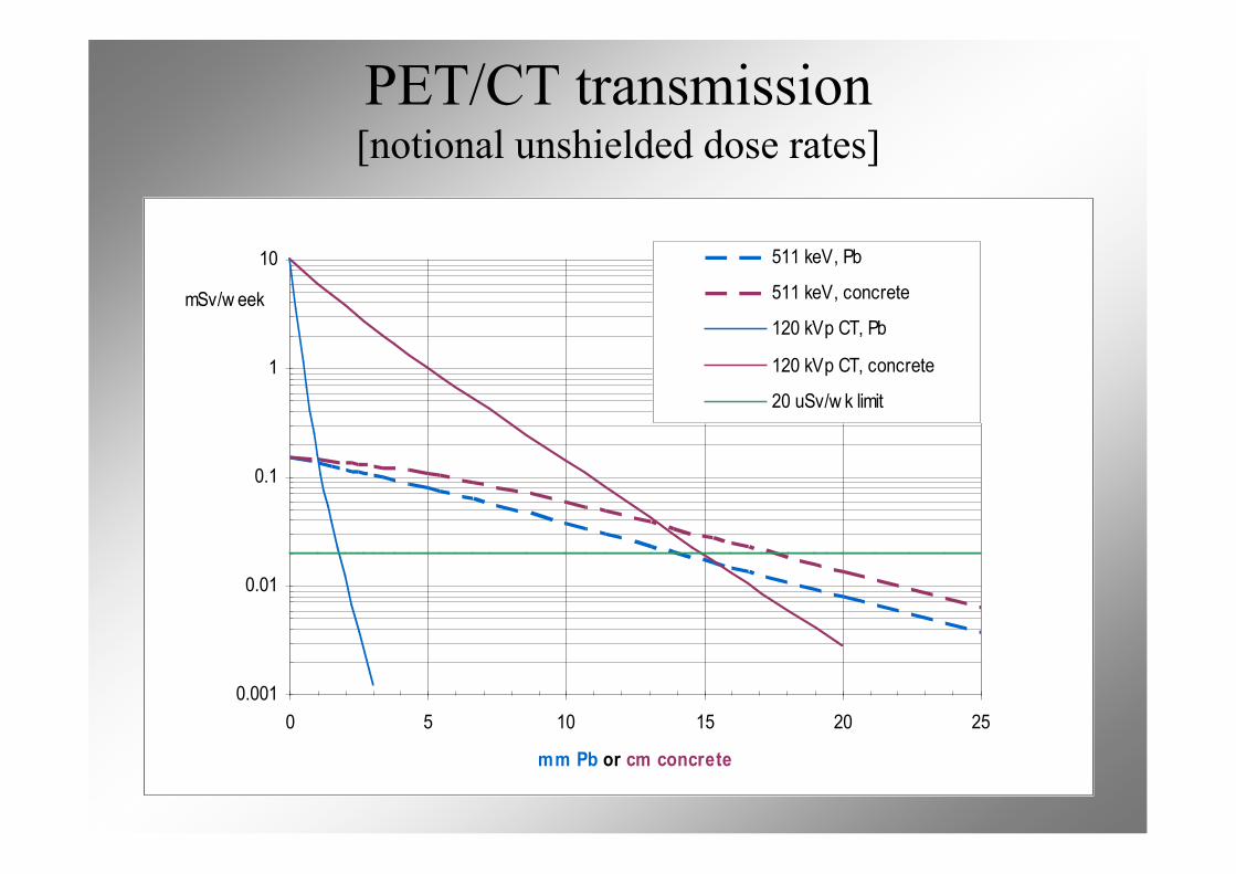
PET/CT transmission[notional unshielded dose rates]
0.001
0.01
0.1
1
10
0 5 10 15 20 25
mm Pb or cm concrete
mSv/w eek
511 keV, Pb
511 keV, concrete
120 kVp CT, Pb
120 kVp CT, concrete
20 uSv/w k limit
Practical details
• Barrier heights• Viewing windows• Barrier penetrations• Raised floors• Barrier labels• Doors
References
• AAPM Task Group 108: PET and PET/CTShielding Requirements. Madsen M et al. MedPhys 33:4-15 (2006)
• NCRP 147 Structural Shielding Design forMedical X-ray Imaging Facilities (2005)
• Archer B et al. Health Phys 44:507-517 (1983)• Simpkin D. Health Phys 56:151-164 (1989) and
58:363-367 (1990)• Radionuclide and Radiation Protection
Handbook. Delacroix et al. RPD 98 No.1 (2002)
Recommended