Cabling forCabling for Healthcare
Carol Everett Oliver, RCDD, ESS Marketing Analyst,Marketing Analyst,
Berk-Tek, a Nexans Company
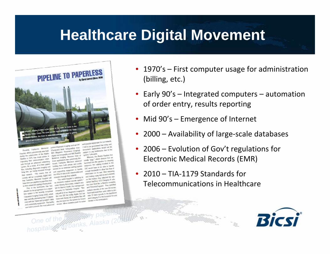
Healthcare Digital Movement
• 1970’s – First computer usage for administration (billing etc )(billing, etc.)
• Early 90’s – Integrated computers – automation of order entry, results reporting
• Mid 90’s – Emergence of Internet
• 2000 – Availability of large-scale databases
• 2006 – Evolution of Gov’t regulations for Electronic Medical Records (EMR)
• 2010 – TIA-1179 Standards for2010 TIA 1179 Standards for Telecommunications in Healthcare
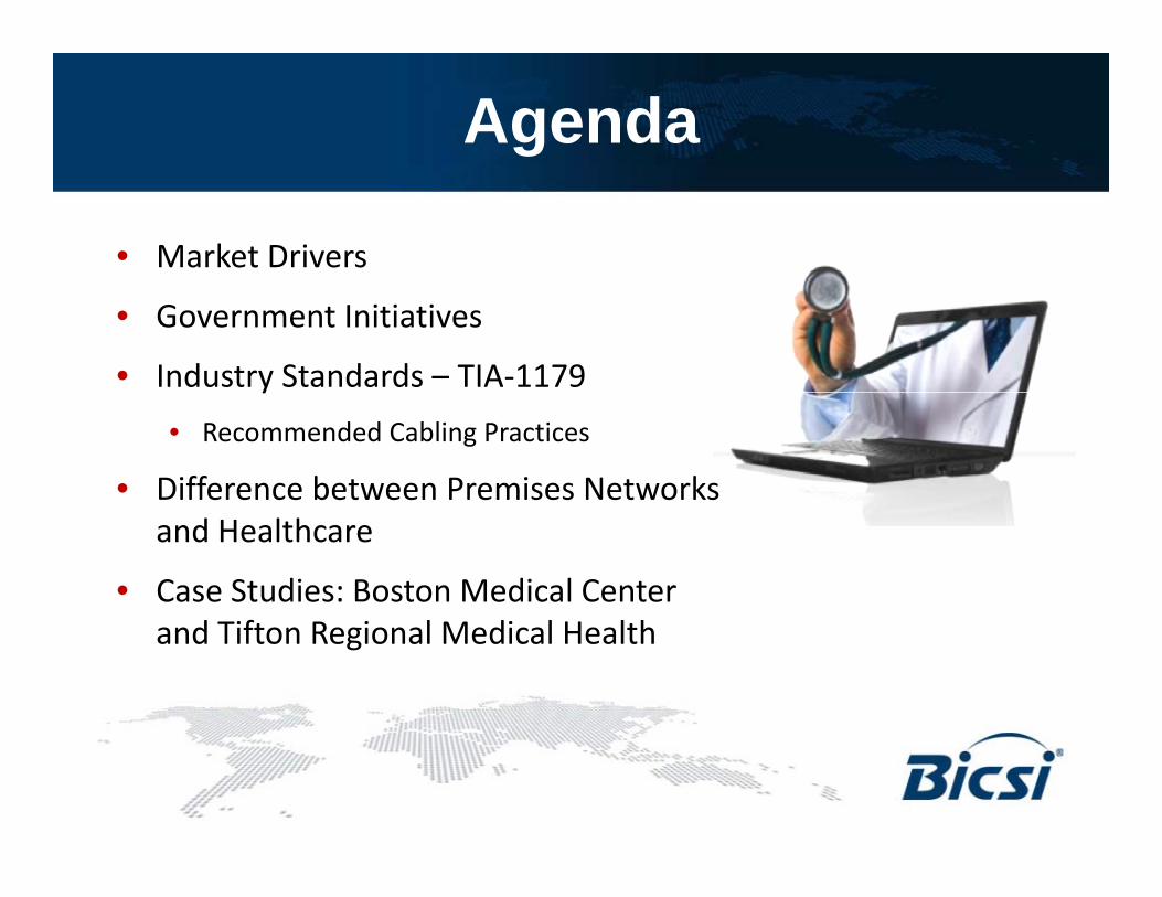
Agenda
• Market Drivers
• Government Initiatives
• Industry Standards – TIA-1179y• Recommended Cabling Practices
• Difference between Premises Networks and Healthcare
• Case Studies: Boston Medical Center and Tifton Regional Medical Health

Market Drivers
• Government Initiatives • Industry Standards – TIA-1179
• Application specific vs. non Application based (568)non-Application based (568)
• Digital media (EMR)• Long distance collaboration &Long distance collaboration &
education in real time• IP Convergence

Exploding Bandwidth Requirements
MRIMRI39 MBUltrasoundUltrasound
18 MBAngiography
15 MB

Gov’t Regulations – HIPAA
• Health Insurance Portability and Accountability Act (HIPAA), y y ( ),enacted 1996
• Addresses the security and privacy of health data • Encourages the use of electronic data interchange in the U.S.
health care system • Establishes regulations for the use and disclosure ofEstablishes regulations for the use and disclosure of
Protected Health Information (PHI) and e-PHI
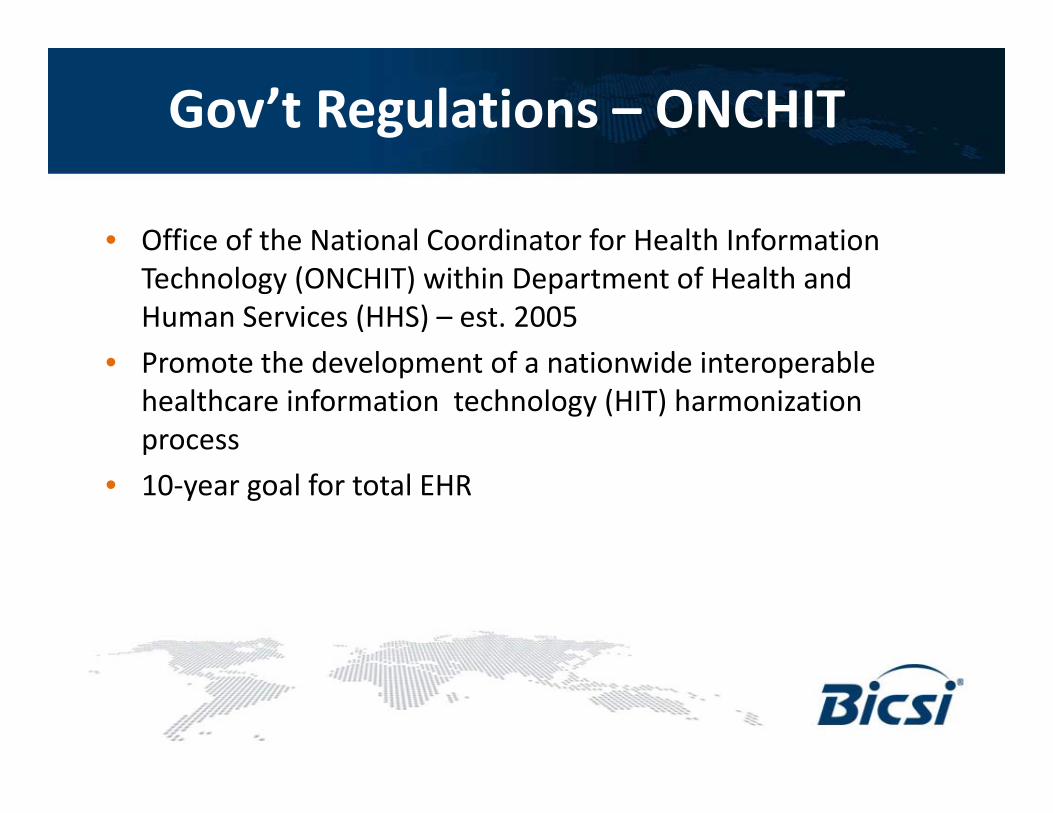
Gov’t Regulations – ONCHIT
• Office of the National Coordinator for Health Information Technology (ONCHIT) within Department of Health and Human Services (HHS) – est. 2005P t th d l t f ti id i t bl• Promote the development of a nationwide interoperable healthcare information technology (HIT) harmonization process
• 10-year goal for total EHR

Gov’t Regulations – ARRA
• American Recovery and Reinvestment Act -- 2009 StimulusAmerican Recovery and Reinvestment Act 2009 Stimulus package – includes healthcare
• Promotes the adoption of interoperable electronic health records (EHRs) to develop a national health information network
• Ends September 2011Ends September 2011• Office of the National Coordinator for Health Information
Technology (ONCHIT) to continue to implement this plan
Gov’t Regulations – HITECH Act
l h f h l f d l l• Health Information Technology for Economic and Clinical Health (HITECH) Act – part of the 2009 ARRA
• Promotes exchange of health information on a national basisPromotes exchange of health information on a national basis• Provides incentives for entities that adopt Electronic Health
Records (EHR)• Widens the scope of privacy and security provisions of HIPAA

Joint Commission (Organization)
• ACCREDITATIONB d i ti d f (A b l t B h i l• Based on organization and focus (Ambulatory, Behavioral, Critical Access, Home Care, Hospital, Lab, Long Term)
• CERTIFICATION• Based on staff and responsibilities of service and safety
• STANDARDS• Operational standards and manuals
• MEASUREMENTS• Performance evaluations – patient tracers and national safety• Performance evaluations – patient tracers and national safety
goals.• Periodic performance assessment
www.jointcommission.org
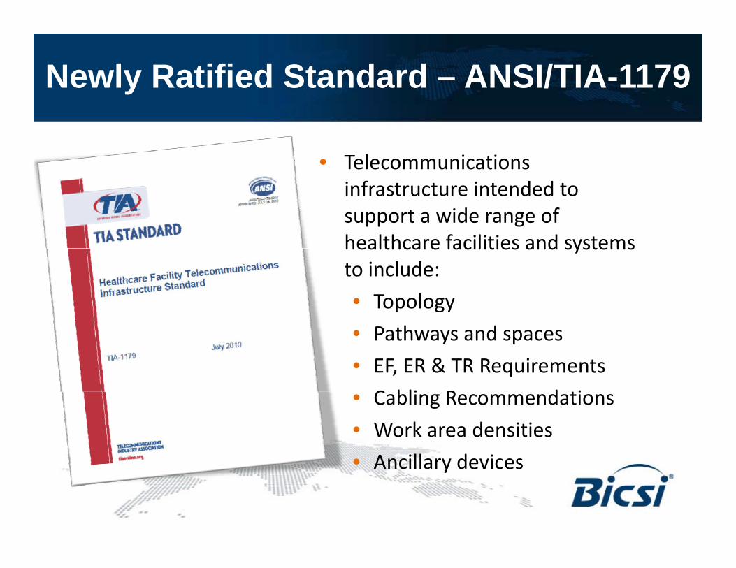
Newly Ratified Standard – ANSI/TIA-1179
• Telecommunications infrastructure intended to support a wide range of healthcare facilities and systemshealthcare facilities and systems to include:• Topology• Pathways and spaces• EF, ER & TR Requirements
C bli R d i• Cabling Recommendations• Work area densities • Ancillary devices• Ancillary devices

Pathway Guidelines
• Pathways should not ycompromise operation of the facility
l d h• Enclosed pathway systems -- in air handling spaces to meet Infection Control Requirements Infection Control Requirements(ICR)
• Segregation of cables for different networks & applications (due to safety protocols)protocols)

Entrance Facilities (EF) &Equipment Rooms (ER)Equipment Rooms (ER)
• Route diversity - two separate pathways from theRoute diversity two separate pathways from the entrance facility to the equipment room
• Demarcation point of outside access providers may• Demarcation point of outside access providers may be determined by federal or local regulations.
d f h• Accommodation of other systems may increase size (BAS, nurse call, security, CATV, biomedical systems)
• Growth factor of 100%

Telecommunications Rooms (TR) and Telecom Enclosures (TE)Telecom Enclosures (TE)
• Non-telecommunications servicesNon telecommunications services (i.e. gasses, fluids) not allowed
• Larger TR than office building --Larger TR than office building 12m2 (130 ft2 ) or larger
• TE serves smaller floor area or• TE serves smaller floor area or where TR is not allowed (be aware of exposure of magnetic fields, p g ,radiation, chemicals, etc)
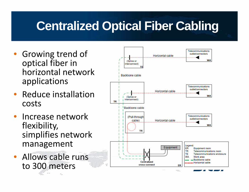
Centralized Optical Fiber Cabling
• Growing trend of l f boptical fiber in
horizontal network applicationsapplications
• Reduce installation costs
• Increase network flexibility, i lifi t ksimplifies network
management• Allows cable runs• Allows cable runs
to 300 meters

Backbone Cabling
• Needs to accommodate future equipment needsequipment needs
• Minimum of two diverse pathways and cables to each TR or TEand cables to each TR or TE
• Recommended cabling:• 100 ohm (Cat 6 or higher)*100 ohm (Cat 6 or higher)• 850nm, LOMF (laser optimized
multimode fiber)• Single-mode
*Notes: Cat 6A is recommended for new installationsCat 3 should be limited to analog voice

Horizontal Cabling
• Plan to accommodate future equipment needs diverse and increasing userneeds, diverse and increasing user application-specific services
• Less accessible than backbone cabling• Less accessible than backbone cabling• During the design, reduce the probability requiring changes to
horizontal cabling
• Recommended cabling:• Category 5e; Category 6 or higher is recommended
N t C t 6A d d f i t ll ti• Note: Category 6A recommended for new installations• Multimode, 850 nm 50/125, 2-fiber or higher• Single-mode, 2-fiber or higher
• Note: Bundled and hybrid cables can be used .

Work Areas
• Based on applications and iusage requirements
• High density drops• 11 Classifications:
• Patient Services • Caregiver• Surgery/Procedure/ Operating Rm • Service/Support• Emergency • Facilities• Ambulatory Care • Operations• Ambulatory Care • Operations• Women’s Health • Critical Care• Diagnostic and Treatment

Work Area Classification Tables
• Tables within the standard list the recommended work area configurations based on the f ti t th t l tifunctions at that location:
• L = Low: 2-6 outlets per area• M = Medium: 6-12 outlets per
area• H = High: >14 outlets in each
area

Work Area Density Tables
• L = Low: 45% of 75 listed including:• Waiting Room, Ambulance Bay, X-Ray, Patient Holding,
Consultation, Mechanical Rooms
• M = Medium: 25% of 75 listed including:g• Registration, Patient Prep & Recovery, Exam & Evaluation,
Nursery, Pharmacy, Administration, Food Service
• H High: 30% of 75 listed including:• H = High: 30% of 75 listed including:• Patient Room, Nurse Station, Intensive Care, Operating
Room, Emergency Procedure, Out-Patient Surgery, Delivery Room MRI CT Scan Lab Security OfficeRoom, MRI, CT Scan, Lab, Security Office
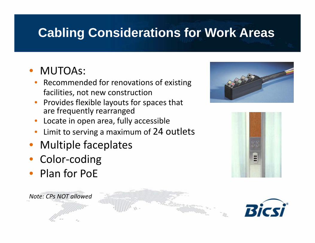
Cabling Considerations for Work Areas
• MUTOAs:• Recommended for renovations of existing
facilities, not new construction• Provides flexible layouts for spaces that y p
are frequently rearranged• Locate in open area, fully accessible• Limit to serving a maximum of 24 outlets
• Multiple faceplates• Color-coding• Plan for PoE
Note: CPs NOT allowedNote: CPs NOT allowed

Unique Cabling Installation Best Practice RecommendationsPractice Recommendations
• High termination work area density recommended to use multi-fiber, preferably pre-term
• High-levels of EMI, high temperatureHigh levels of EMI, high temperature and chemicals may be present
• Cabling products with unique attributes to comply withattributes to comply with atmospheric conditions
• Use of colored cables, jacks and k d i i i ikeyed connectivity to maintain segregation of the networks
• Become familiar with unique codes qand regulations

Healthcare vs. Premises
• Broader scope of application-specific IP devices
• Sensitive installation environment
• Larger pathways• Larger Telecom Rooms• Work area classifications
and densities
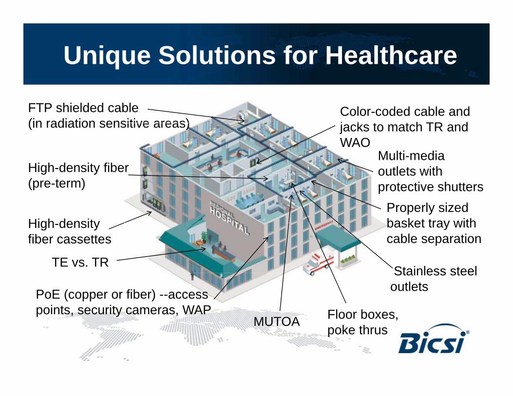
Unique Solutions for Healthcare
FTP shielded cable (in radiation sensitive areas)
Color-coded cable and j k t t h TR d
High-density fiber
(in radiation sensitive areas)
Multi-media outlets with
jacks to match TR and WAO
Properly sized basket tray with
g y(pre-term)
High density
outlets with protective shutters
basket tray with cable separation
High-density fiber cassettes
TE vs. TRStainless steel
MUTOA Floor boxes, PoE (copper or fiber) --access points, security cameras, WAP
Stainless steel outlets
MUTOA poke thrus
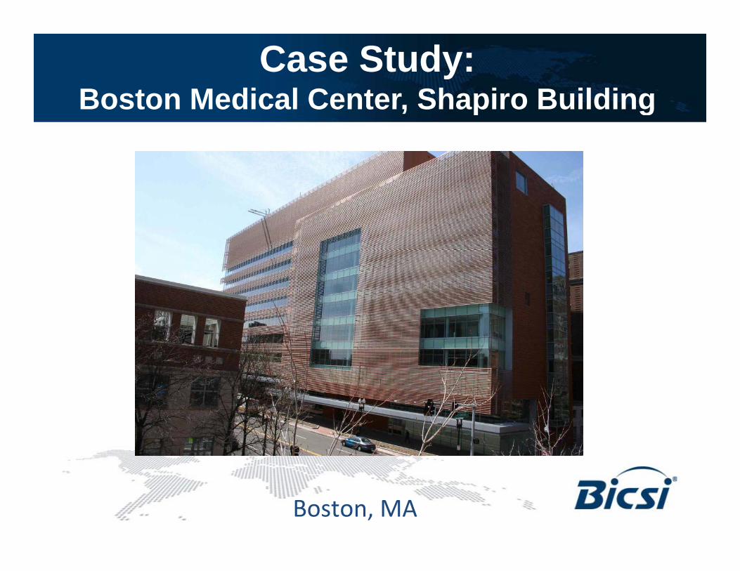
Case Study: Boston Medical Center, Shapiro BuildingBoston Medical Center, Shapiro Building
Boston, MA

Case Study: BMCShapiro Building StatsS ap o u d g Stats
• Boston Medical Center -- 26 building campusos o ed ca e e 6 bu d g ca pus• New Building: Shapiro Building Ambulatory Care –
outpatient services (orthopedics, neurology, dermatology, cosmotology, general day surgery, etc)• 9 stories, 250,000 sq. ft.• Five years construction: two years to relocate and
raise previous bldg.

Case Study: Shapiro (BMC)Unique ChallengesU que C a e ges
“Old S h l/N S h l”• “Old School/New School”• Diverse and high-bandwidth
applicationsapplications• High-density applications
N d t ll f f t• Need to allow for future expansion and IP Convergence
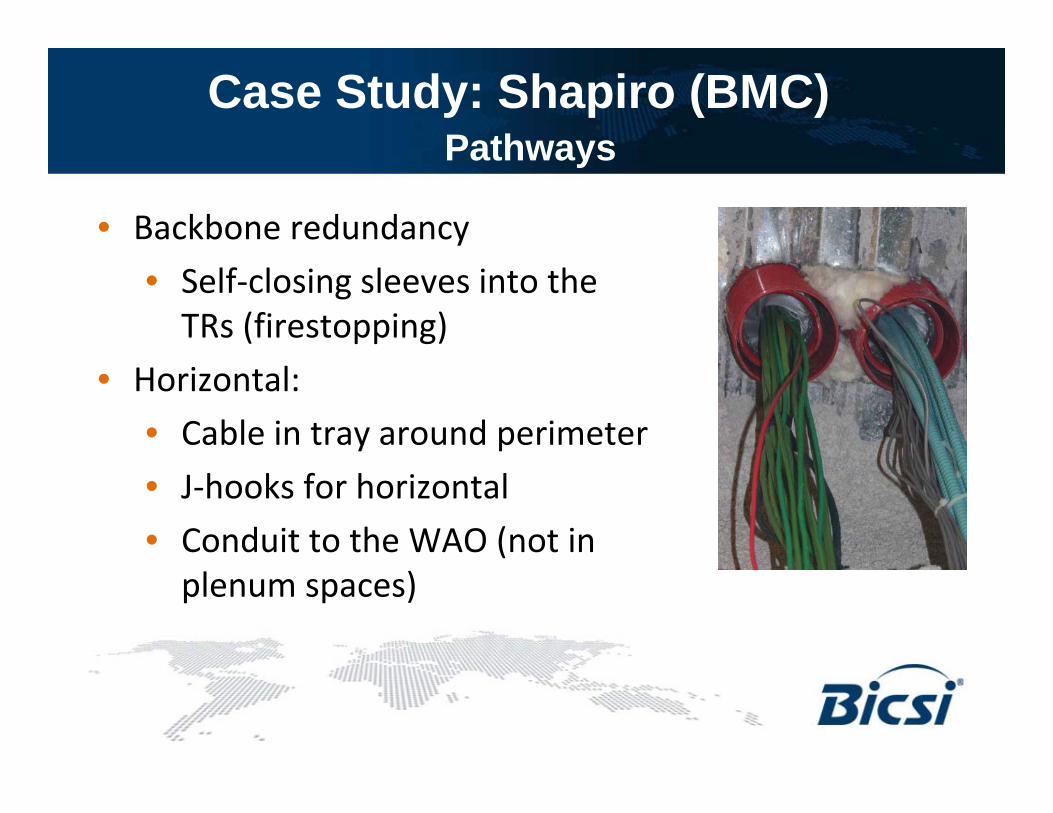
Case Study: Shapiro (BMC)PathwaysPathways
• Backbone redundancy• Self-closing sleeves into the
TRs (firestopping)• Horizontal:
• Cable in tray around perimeter• J-hooks for horizontal• Conduit to the WAO (not in
plenum spaces)

Case Study: Shapiro (BMC)Backbone cablingBackbone cabling
• Armored Cable:• SM (APC Connectors) –
mainly for video• MM:
• 24 strands of 62.5 (mainly for voice)
• 24 strands of 50µ(data and IP)

Case Study: Shapiro (BMC)Telecom RoomTelecom Room
• Two MDFs (10x13)• Two MDFs (10x13)• Two TRs per floor (located in the
middle of the floor)middle of the floor)• 800 horizontal cables per floor• 100% patching to limit client services• 100% patching to limit client services
traffic into TR: VLAN for MACs
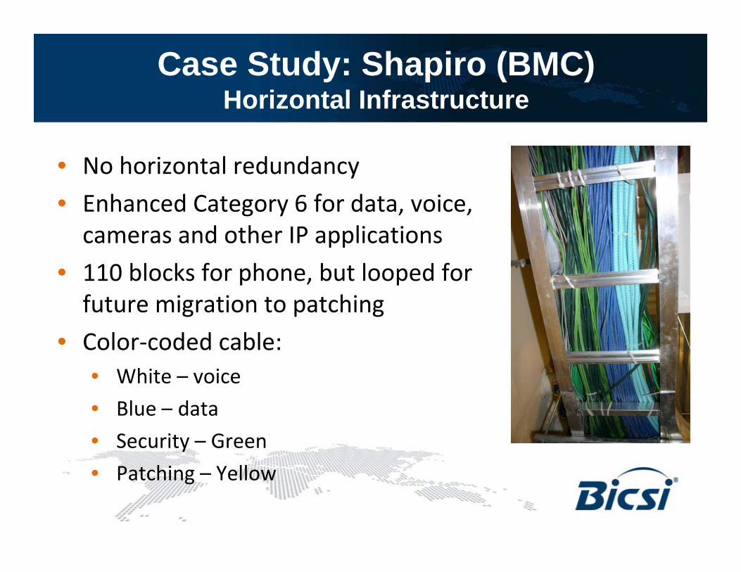
Case Study: Shapiro (BMC)Horizontal InfrastructureHorizontal Infrastructure
• No horizontal redundancyy• Enhanced Category 6 for data, voice,
cameras and other IP applications• 110 blocks for phone, but looped for
future migration to patching• Color-coded cable:
• White – voice• Blue – data• Security – Green
P hi Y ll• Patching – Yellow

Case Study: Shapiro (BMC)Work AreasWork Areas
• 800 cable runs per floorp• 6-port stainless steel faceplates with
blue/white color-coding• Sealed/fire-rated outlets for
firestopping and sound• PoE to all wireless APs and security
cameras

Case Study: Shapiro (BMC)Lessons LearnedLessons Learned
• Pre-planning for sizing of the sleevesp g g• No plenum (no mixing with HVAC)• Armored cable – saves time and cost,
b t d dibut needs grounding• Higher grade Category 6 for new
facilities• Cable category inconsistency - Old
with New: (MACs) – older facilities using older cable (Cat 5e vs 6)using older cable (Cat 5e vs. 6)
• Total patching environment – ease of MAC
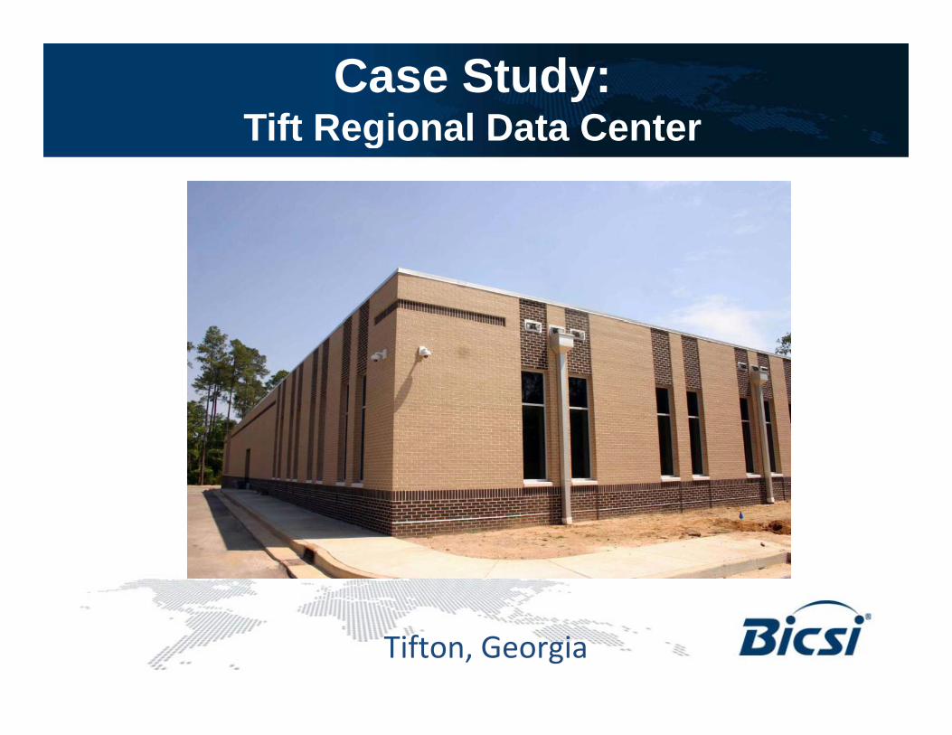
Case Study: Tift Regional Data CenterTift Regional Data Center
Tifton, Georgia

Case Study: Tift Reg. Data CenterStatsStats
• Built in 1965 as a u 965 as acommunity hospital
• Today – regional hospital for 6 counties
• Region of 250,000 lpeople
• 151,000 square feet –26 buildings26 buildings
• Situated in “Tornado Alley”y

Case Study: Tift Reg. Data CenterOld Cable Plant – Networking ChallengeOld Cable Plant – Networking Challenge
• One 24-strand fiber cable backbone under city streets
• MDF located in old doctor’s offices
• Frequent power outages• No redundancy• No centralized data center

Case Study: Tift Reg. Data CenterData Center StatsData Center Stats
• $10 million• Tier 2 (N+1)• Redundant fiber ring• Redundant networks• 15,000 square feet, q• Plans to double size in 5 years• 10 CRAC units, 2 generators10 CRAC units, 2 generators• CPOE (Computerized Physician
Order Entry) – working towards y) gtotal EMR
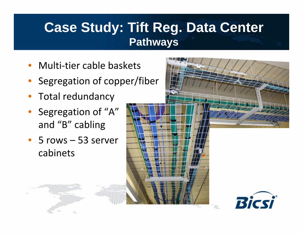
Case Study: Tift Reg. Data CenterPathwaysPathways
• Multi-tier cable baskets• Segregation of copper/fiber• Total redundancy• Segregation of “A”
and “B” cabling • 5 rows – 53 server
cabinets
Case Study: Tift Reg. Data Center Backbone
• OSP:
Backbone
• Diverse fiber ring• Two – 72-strand SM in ductbanks
• Hospital• Armored 72-strand SM cable within the
hospital (10G to each building)• Data Center:
• 24-strand SM to SAN area – Total redundancy
• 15 10G on each switch (200 10G ports)

Case Study: Tift Reg. Data CenterHorizontal InfrastructureHorizontal Infrastructure
• OM3 LOMF from switches to server rows -10 Gig
• Redundant 24 strands from switch to each server cabineteach server cabinet
• 5,088 anaerobic field terminations• Category 6 Copper connections to• Category 6 Copper connections to
each server cabinets (total – 1,060)• Color-coded cable:
• Patch cables – Green for “A” side, Blue for “B” sideP l CCTV/S it d BAS• Purple – CCTV/Security and BAS
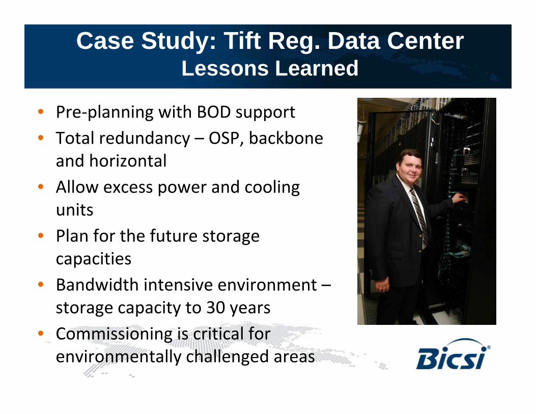
Case Study: Tift Reg. Data CenterLessons Learned
• Pre-planning with BOD support• Total redundancy – OSP, backbone
and horizontalAll d li• Allow excess power and cooling units
• Plan for the future storage• Plan for the future storage capacities
• Bandwidth intensive environment –• Bandwidth intensive environment –storage capacity to 30 years
• Commissioning is critical forCommissioning is critical for environmentally challenged areas

QuestionsContact:
Carol Everett Oliver RCDD ESSCarol Everett Oliver, RCDD, [email protected]
Thank you Thank you, Thank you, Brian
y ,Mel
Recommended