2010-05-10
1
Ca Looping: a New Technology forCa Looping: a New Technology for CO2 Capture
E.J. “Ben” Anthony
G L d FBC & G ifi ti
60th IEA FBC Meeting, Gothenburg, Sweden
Group Leader FBC & GasificationCanmetENERGY, Natural Resources Canada
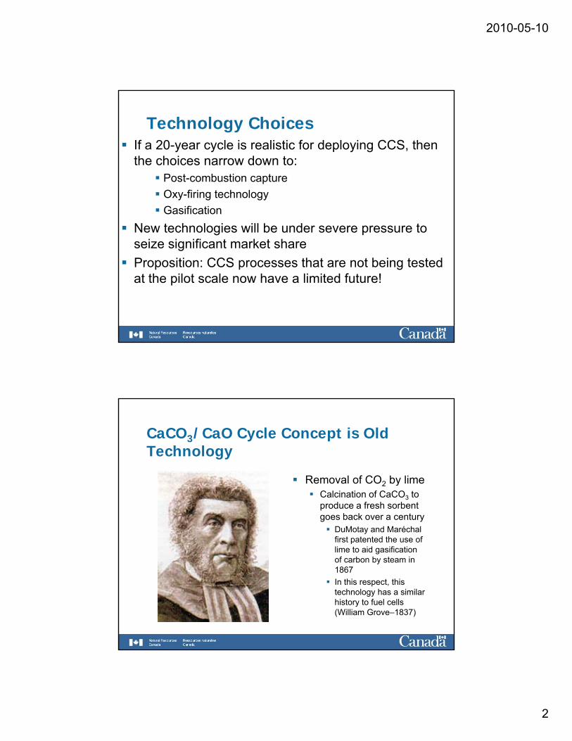
Anthropogenic Global Warming “The examples, so far as they go, demonstrate that comparatively unimportant variations in the composition of the air have avariations in the composition of the air have a very great influence…On the other hand, any doubling of the percentage of the carbon dioxide in the air would raise the temperature of the earth’s surface by 4˚…”- Professor Svante Arrhenius
Extract from pg. 52 of “Worlds in the Making”, Harper and Brothers Publishers, 1907.
We have known about global warming for over 100 years!
Increasingly there is a conviction that we need to have CCS ready within the next few decades!
2010-05-10
2
Technology ChoicesIf a 20-year cycle is realistic for deploying CCS, then the choices narrow down to:
P t b ti tPost-combustion captureOxy-firing technologyGasification
New technologies will be under severe pressure to seize significant market shareP iti CCS th t t b i t t dProposition: CCS processes that are not being tested at the pilot scale now have a limited future!
CaCO3/CaO Cycle Concept is Old Technology
Removal of CO2 by limeRemoval of CO2 by limeCalcination of CaCO3 to produce a fresh sorbent goes back over a century
DuMotay and Maréchal first patented the use of lime to aid gasification of carbon by steam in 1867In this respect, this technology has a similar history to fuel cells (William Grove–1837)
2010-05-10
3
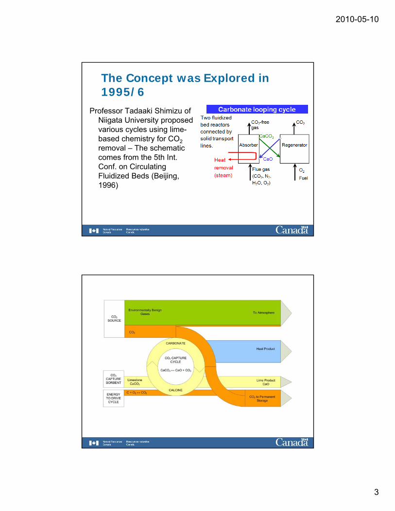
The Concept was Explored in 1995/6
Professor Tadaaki Shimizu of Niigata University proposedNiigata University proposed various cycles using lime-based chemistry for CO2removal – The schematic comes from the 5th Int. Conf. on Circulating Fluidized Beds (Beijing,Fluidized Beds (Beijing, 1996)
2010-05-10
4
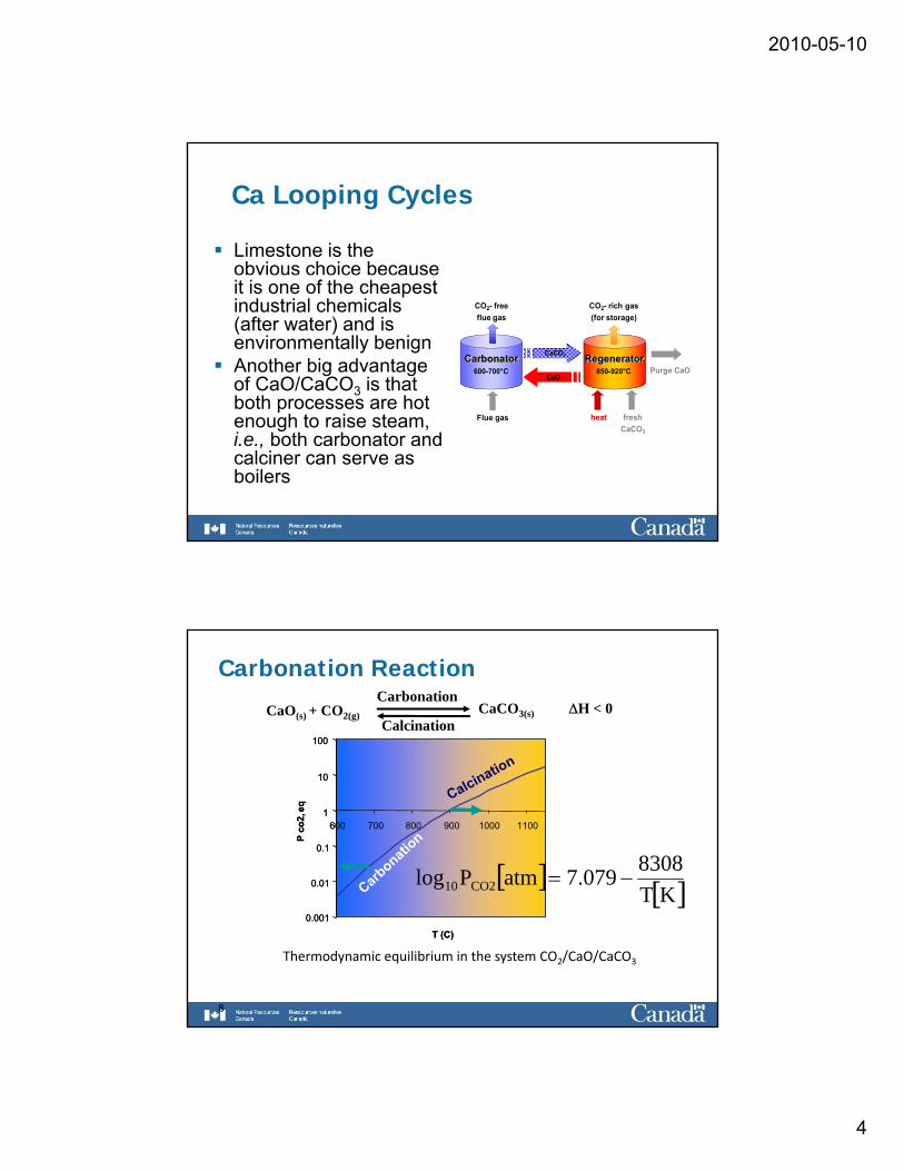
Ca Looping Cycles
Limestone is the obvious choice because it is one of the cheapest industrial chemicals (after water) and is environmentally benign Another big advantage of CaO/CaCO3 is that both processes are hot
Carbonator600-700°C
Regenerator850-920°C
CO2- freeflue gas
CaO
CaCO3
CO2- rich gas(for storage)
Purge CaO
both processes are hot enough to raise steam, i.e., both carbonator and calciner can serve as boilers
Flue gas heat freshCaCO3
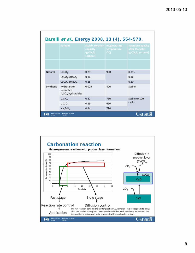
Carbonation Reaction
CaO(s) + CO2(g) CaCO3(s) ΔH < 0Carbonation
Calcination100
on100
on
0.01
0.1
1
10
600 700 800 900 1000 1100
P co
2, e
q
Carbonati
on
Calcination
0.01
0.1
1
10
600 700 800 900 1000 1100
P co
2, e
q
Carbonati
on
Calcination
[ ] [ ]KT83087.079atmPlog CO210 −=
8
0.001
T (C)
0.001
T (C)
Thermodynamic equilibrium in the system CO2/CaO/CaCO3
[ ]KT
2010-05-10
5
Barelli et al., Energy 2008, 33 (4), 554-570.Sorbent Stoich. sorption
capacity (g CO2/g sorbent)
Regenerating temperature (°C)
Sorption capacity after 45 cycles(g CO2/g sorbent)
Natural CaCO3 0.79 900 0.316
CaCO3∙MgCO3 0.46 0.16
CaCO3∙3MgCO3 0.25 0.20
Synthetic Hydrotalcite, 0.029 400 Stablepromoted K2CO3/hydrotalcite
Li4SiO4 0.37 750 Stable to 100 cyclesLi2ZrO3 0.29 690
Na2ZrO3 0.24 790
Carbonation reaction
70
80
90
100
gree
[%]
Heterogeneous reaction with product layer formationDiffusion inproduct layer
(CaCO3)
0
10
20
3040
50
60
0 5 10 15 20 25 30 35 40
Time [min]
Car
boni
zatio
n de
g
CO2
CaO
CO2
CaCO3
10
Fast stage Slow stage
Reaction rate control Diffusion control
Application
CaO
The fast reaction period is the key for practical CO2 removal. This corresponds to filling of all the smaller pore spaces. Bench‐scale and other work has clearly established that the reaction is fast enough to be employed with a combustion system.
2010-05-10
6
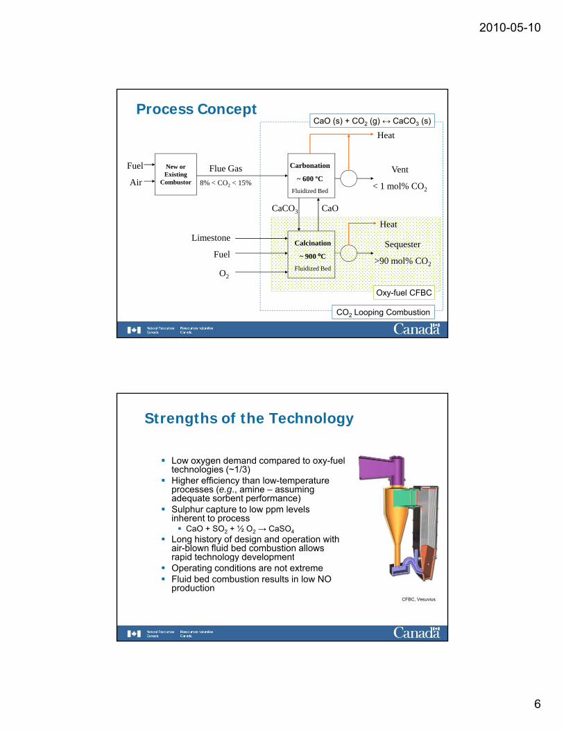
Process Concept
CarbonationNew or Fuel Flue Gas
Heat
Vent
CaO (s) + CO2 (g) ↔ CaCO3 (s)
~ 600 ºCFluidized Bed
Calcination
900 ºC
Existing Combustor
CaCO3 CaO
SequesterFuel
Air 8% < CO2 < 15%
Heat
Vent
< 1 mol% CO2
Limestone
~ 900 ºCFluidized Bed
>90 mol% CO2Fuel
O2
Oxy-fuel CFBC
CO2 Looping Combustion
Strengths of the Technology
Low oxygen demand compared to oxy-fuel technologies (~1/3)Higher efficiency than low-temperature processes (e.g., amine – assuming adequate sorbent performance)Sulphur capture to low ppm levels inherent to process
CaO + SO2 + ½ O2 → CaSO4Long history of design and operation with air-blown fluid bed combustion allows rapid technology developmentrapid technology developmentOperating conditions are not extremeFluid bed combustion results in low NO production
CFBC, Vesuvius
2010-05-10
7
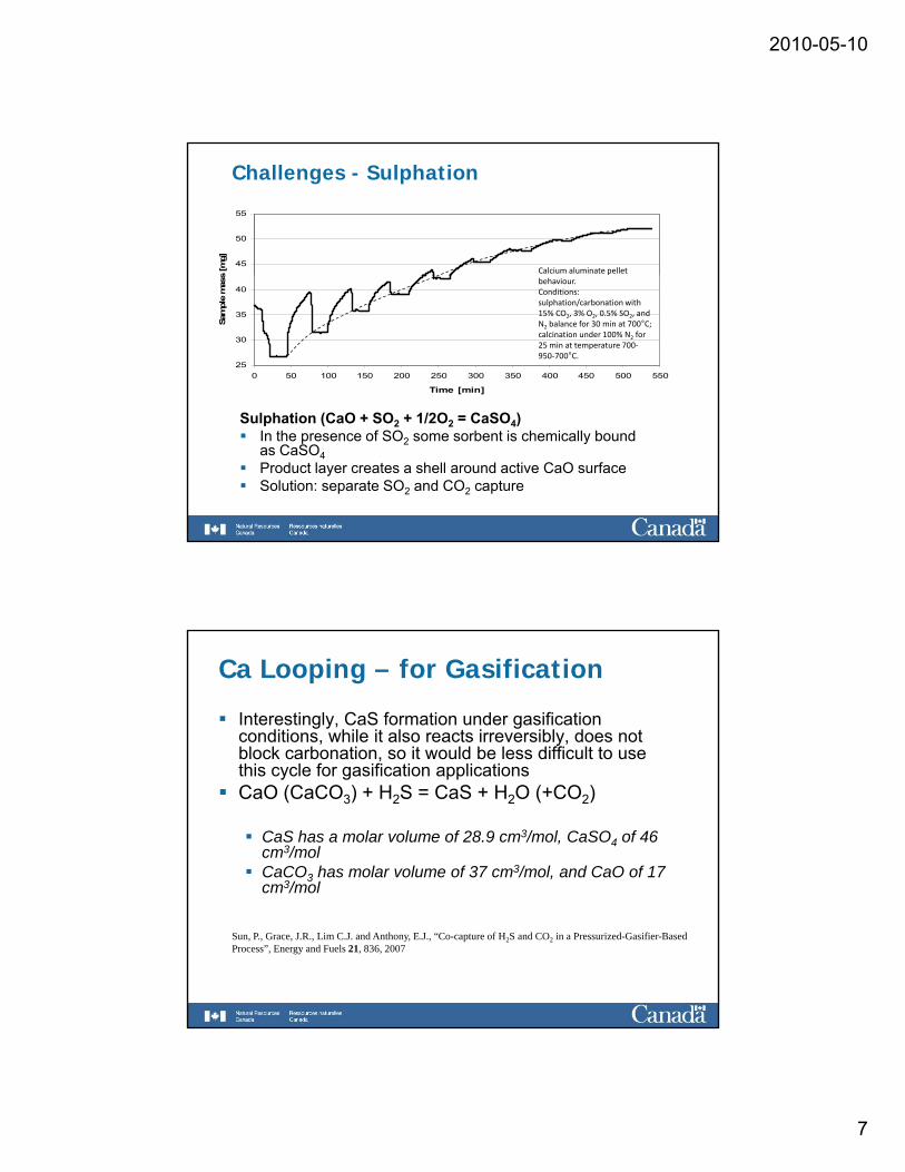
Challenges - Sulphation
45
50
55s
[mg]
Calcium aluminate pellet
25
30
35
40
0 50 100 150 200 250 300 350 400 450 500 550
Time [min]
Sam
ple
mas
s
behaviour. Conditions: sulphation/carbonation with 15% CO2, 3% O2, 0.5% SO2, and N2 balance for 30 min at 700°C; calcination under 100% N2 for 25 min at temperature 700‐950‐700°C.
Sulphation (CaO + SO2 + 1/2O2 = CaSO4)In the presence of SO2 some sorbent is chemically bound as CaSO4Product layer creates a shell around active CaO surfaceSolution: separate SO2 and CO2 capture
Ca Looping – for Gasification
Interestingly, CaS formation under gasification conditions, while it also reacts irreversibly, does not block carbonation, so it would be less difficult to use this cycle for gasification applicationsCaO (CaCO3) + H2S = CaS + H2O (+CO2)
CaS has a molar volume of 28.9 cm3/mol, CaSO4 of 46 cm3/molCaCO3 has molar volume of 37 cm3/mol, and CaO of 17 cm3/mol
Sun, P., Grace, J.R., Lim C.J. and Anthony, E.J., “Co-capture of H2S and CO2 in a Pressurized-Gasifier-Based Process”, Energy and Fuels 21, 836, 2007
2010-05-10
8
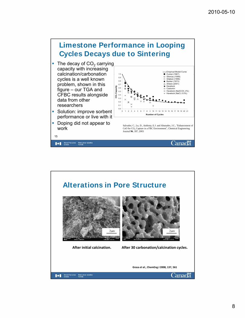
Limestone Performance in Looping Cycles Decays due to Sintering
The decay of CO2 carrying capacity with increasing calcination/carbonation 1.0
Emprical Model CurveCurran (1967)calcination/carbonation
cycles is a well known problem, shown in this figure – our TGA and CFBC results alongside data from other researchersSolution: improve sorbent
0.0
0.1
0.2
0.3
0.4
0.5
0.6
0.7
0.8
0.9
0 1 2 3 4 5 6 7 8 9 10 11 12 13 14 15 16 17 18 19 20 21
CO
2 Cap
acity
Curran (1967)Shimizu (1999)Silaban (1996)Barker (1973)Aihara (2001)HavelockCadominHavelock (Na2CO3, 4%)Havelock (NaCl, 0.5%)
15
Solution: improve sorbent performance or live with it Doping did not appear to work
0 1 2 3 4 5 6 7 8 9 10 11 12 13 14 15 16 17 18 19 20 21
Number of Cycles
Salvador, C., Lu, D., Anthony, E.J. and Abanades, J.C., “Enhancement of CaO for CO2 Capture in a FBC Environment”, Chemical Engineering Journal 96, 187, 2003
Alterations in Pore Structure
After initial calcination. After 30 carbonation/calcination cycles.
Grasa et al., ChemEng J 2008, 137, 561
2010-05-10
9
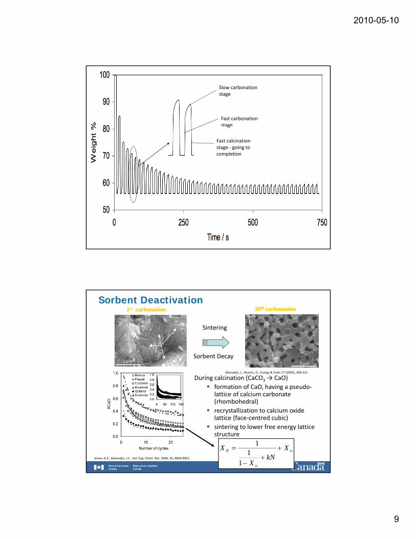
Slow carbonation stage
Fast carbonation stageg
Fast calcination stage ‐ going to completion
Sorbent Deactivation1st carbonation
a
1st carbonation
aSintering
b
30th carbonation
b
30th carbonation
2 μm2 μm 2 μm2 μmSorbent Decay
During calcination (CaCO3 → CaO)formation of CaO, having a pseudo‐lattice of calcium carbonate (rhombohedral)recrystallization to calcium oxide
Abanades, J., Alvarez, D., Energy & Fuels 17 (2003), 308‐315
recrystallization to calcium oxide lattice (face‐centred cubic)sintering to lower free energy lattice structure
Grasa, G.S., Abanades, J.C., Ind. Eng. Chem. Res. 2006, 45, 8846‐8851
∞
∞
++
−
= XkN
X
X N
11
1
2010-05-10
10
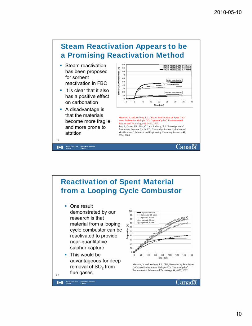
Steam Reactivation Appears to be a Promising Reactivation Method
Steam reactivation has been proposed for sorbent
70
80
90
100
ar ra
tio [%
] KR22, KR37 (0.075-0.150 mm)KR23, KR38 (0.300-0.425 mm)KR24, KR39 (0.600-0.750 mm)
for sorbent reactivation in FBCIt is clear that it also has a positive effect on carbonationA disadvantage is th t th t i l
0
10
20
30
40
50
60
0 5 10 15 20 25 30 35 40
Time [min]
Tota
l CO
2/C
aO m
ola
Before reactivation
After reactivation
19
that the materials become more fragile and more prone to attrition
Manovic, V. and Anthony, E.J., “Steam Reactivation of Spent CaO-based Sorbent for Multiple CO2 Capture Cycles”, Environmental Science and Technology 41, 1420, 2007.Sun, P., Grace, J.R., Lim, C.J. and Anthony, E.J. “Investigation of Attempts to Improve Cyclic CO2 Capture by Sorbent Hydration and Modifications”, Industrial and Engineering Chemistry Research 47, 2024, 2008.
Reactivation of Spent Material from a Looping Cycle Combustor
One result demonstrated by our 100
O i i l li tdemonstrated by our research is that material from a looping cycle combustor can be reactivated to provide near-quantitative sulphur capture 10
20
30
40
50
60
70
80
90
Sulp
hatio
n [%
]
Original limestoneCarbonator #4, spentHydrated, 15 minHydrated, 30 minHydrated, 60 min
20
sulphur captureThis would be advantageous for deep removal of SO2 from flue gases
00 20 40 60 80 100 120 140 160
Time [min]
Manovic, V. and Anthony, E.J., “SO2 Retention by Reactivated CaO-based Sorbent from Multiple CO2 Capture Cycles”, Environmental Science and Technology 41, 4435, 2007
2010-05-10
11
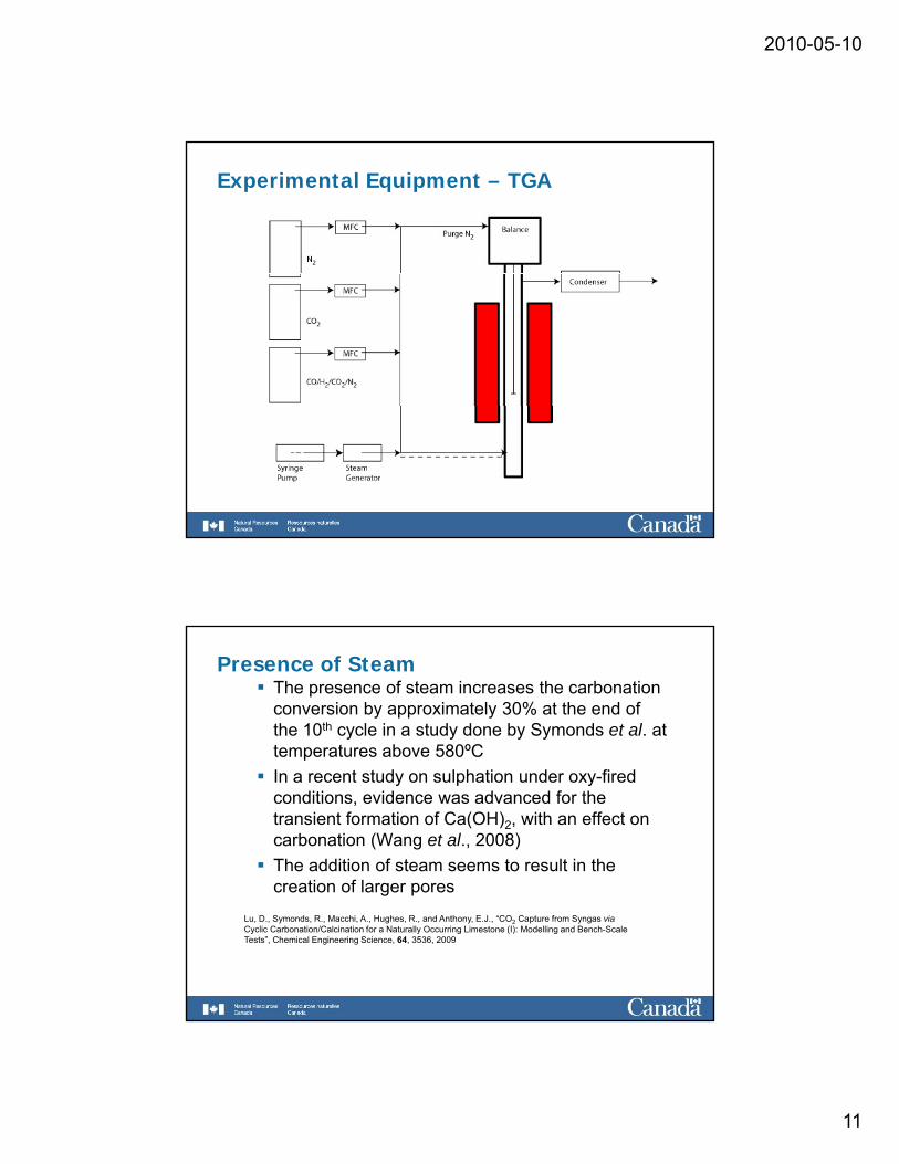
Experimental Equipment – TGA
Presence of SteamThe presence of steam increases the carbonation conversion by approximately 30% at the end of the 10th cycle in a study done by Symonds et al. at temperatures above 580ºCpIn a recent study on sulphation under oxy-fired conditions, evidence was advanced for the transient formation of Ca(OH)2, with an effect on carbonation (Wang et al., 2008)The addition of steam seems to result in the creation of larger porescreation of larger pores
Lu, D., Symonds, R., Macchi, A., Hughes, R., and Anthony, E.J., “CO2 Capture from Syngas viaCyclic Carbonation/Calcination for a Naturally Occurring Limestone (I): Modelling and Bench-Scale Tests”, Chemical Engineering Science, 64, 3536, 2009
2010-05-10
12
6
7
8
l%)
600
700
800
e (o C
)
Steam Addition
Symonds, R., Lu, D., Hughes,
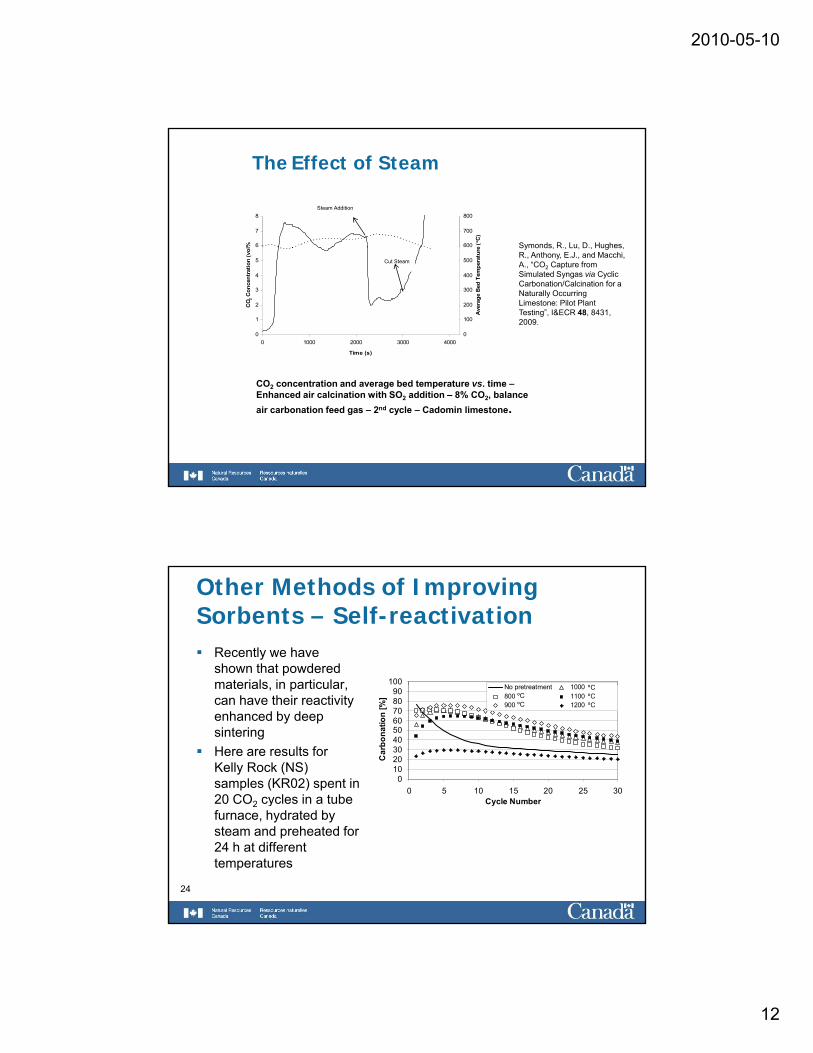
The Effect of Steam
0
1
2
3
4
5
0 1000 2000 3000 4000
Time (s)
CO 2
Con
cent
ratio
n (v
ol
0
100
200
300
400
500
Ave
rage
Bed
Tem
pera
ture
Cut Steam
Symonds, R., Lu, D., Hughes, R., Anthony, E.J., and Macchi, A., “CO2 Capture from Simulated Syngas via Cyclic Carbonation/Calcination for a Naturally Occurring Limestone: Pilot Plant Testing”, I&ECR 48, 8431, 2009.
CO2 concentration and average bed temperature vs. time –Enhanced air calcination with SO2 addition – 8% CO2, balance air carbonation feed gas – 2nd cycle – Cadomin limestone.
Other Methods of Improving Sorbents – Self-reactivation
Recently we have shown that powdered materials in particular 100
N t t t 1000 CºCmaterials, in particular, can have their reactivity enhanced by deep sinteringHere are results for Kelly Rock (NS) samples (KR02) spent in 20 CO2 cycles in a tube
0102030405060708090
0 5 10 15 20 25 30Cycle Number
Car
bona
tion
[%]
No pretreatment 1000 oC800 oC 1100 oC900 oC 1200 oC
ºCºCºC
ºCºC
24
2 yfurnace, hydrated by steam and preheated for 24 h at different temperatures
y
2010-05-10
13
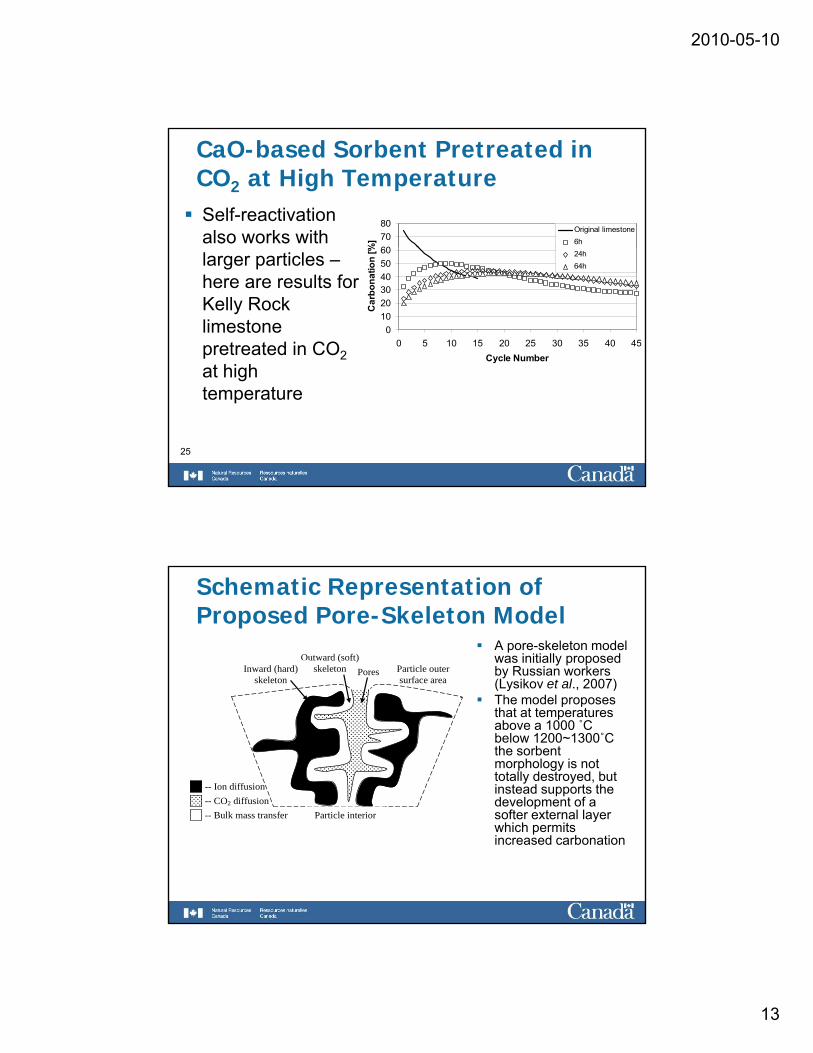
CaO-based Sorbent Pretreated in CO2 at High TemperatureSelf-reactivation also works with
607080
%]
Original limestone6h
larger particles –here are results for Kelly Rock limestone pretreated in CO2
t hi h
0102030405060
0 5 10 15 20 25 30 35 40 45Cycle Number
Car
bona
tion
[% 24h64h
25
at high temperature
Schematic Representation of Proposed Pore-Skeleton Model
Outward (soft) skeleton Inward (hard)
skeleton Pores Particle outer
surface area
A pore-skeleton model was initially proposed by Russian workers (Lysikov et al 2007)
-- Ion diffusion -- CO2 diffusion
(Lysikov et al., 2007)The model proposes that at temperatures above a 1000 ˚Cbelow 1200~1300˚C the sorbent morphology is not totally destroyed, but instead supports the development of a
Particle interior 2
-- Bulk mass transfer development of a softer external layer which permits increased carbonation
2010-05-10
14
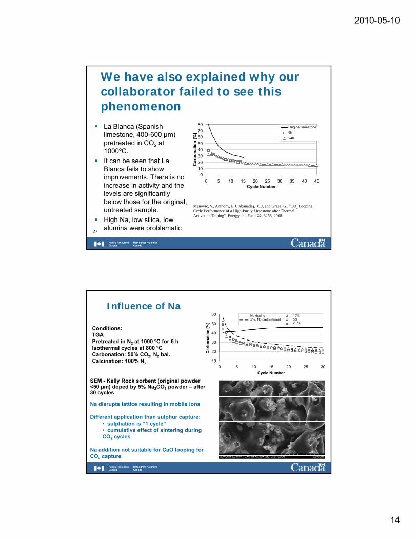
We have also explained why our collaborator failed to see this phenomenonLa Blanca (Spanish 80 Original limestoneLa Blanca (Spanish limestone, 400-600 µm) pretreated in CO2 at 1000ºC.It can be seen that La Blanca fails to show improvements. There is no increase in activity and the
010203040506070
0 5 10 15 20 25 30 35 40 45Cycle Number
Car
bona
tion
[%]
Original limestone6h24h
27
ylevels are significantly below those for the original, untreated sample.High Na, low silica, low alumina were problematic
y
•.Manovic, V., Anthony, E.J. Abanades, C.J, and Grasa, G., “CO2 Looping Cycle Performance of a High-Purity Limestone after Thermal Activation/Doping", Energy and Fuels 22, 3258, 2008.
Influence of Na
20
30
40
50
60
Car
bona
tion
[%]
No doping 10%5%, No pretreatment 5%
2.5%
Conditions:TGAPretreated in N2 at 1000 ºC for 6 hIsothermal cycles at 800 °C
10
20
0 5 10 15 20 25 30Cycle Number
CCarbonation: 50% CO2, N2 bal.Calcination: 100% N2
SEM - Kelly Rock sorbent (original powder <50 µm) doped by 5% Na2CO3 powder – after 30 cycles
Na disrupts lattice resulting in mobile ions
Different application than sulphur capture:• sulphation is “1 cycle”• cumulative effect of sintering during CO2 cycles
Na addition not suitable for CaO looping for CO2 capture
2010-05-10
15
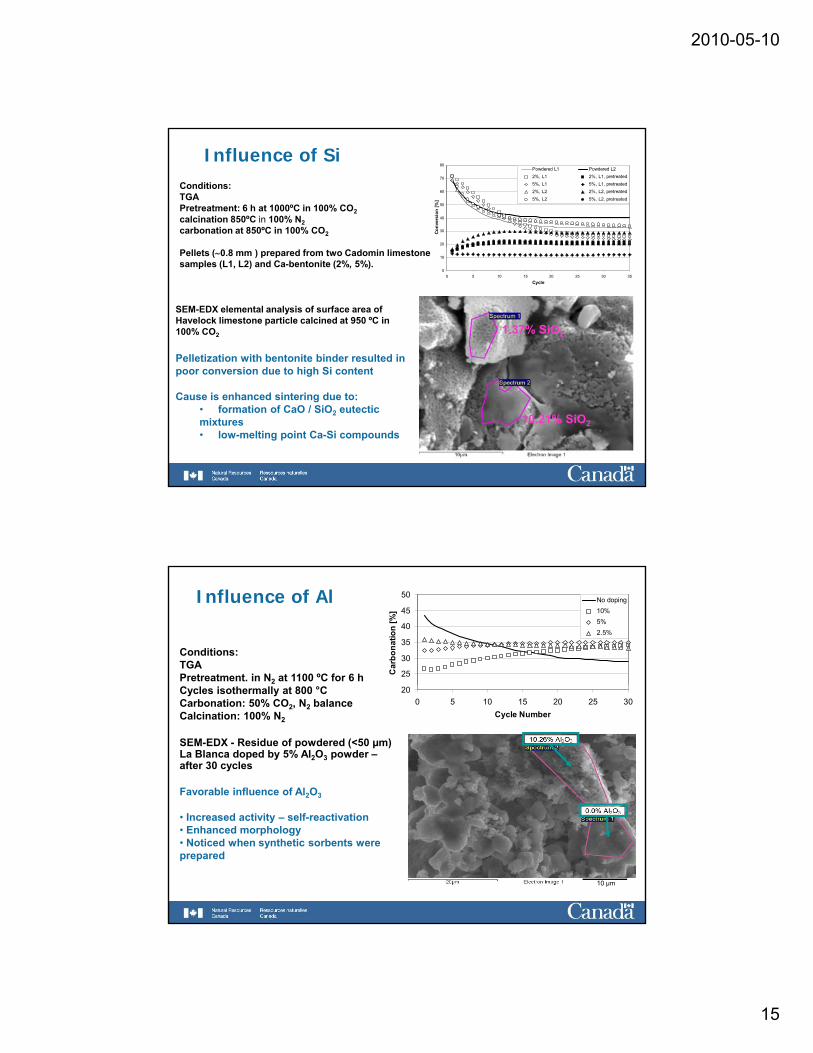
Influence of SiConditions:TGAPretreatment: 6 h at 1000ºC in 100% CO2calcination 850ºC in 100% N2carbonation at 850ºC in 100% CO2
20
30
40
50
60
70
80
Conv
ersi
on [%
]
Powdered L1 Powdered L22%, L1 2%, L1, pretreated5%, L1 5%, L1, pretreated2%, L2 2%, L2, pretreated5%, L2 5%, L2, pretreated
1.37% SiO2
SEM-EDX elemental analysis of surface area of Havelock limestone particle calcined at 950 ºC in 100% CO2
Pelletization with bentonite binder resulted in i d t hi h Si t t
Pellets (∼0.8 mm ) prepared from two Cadomin limestone samples (L1, L2) and Ca-bentonite (2%, 5%).
0
10
0 5 10 15 20 25 30 35Cycle
10.21% SiO2
poor conversion due to high Si content
Cause is enhanced sintering due to:• formation of CaO / SiO2 eutectic mixtures• low-melting point Ca-Si compounds
Influence of Al
25
30
35
40
45
50
Car
bona
tion
[%]
No doping10%5%2.5%
Conditions:TGAPretreatment. in N2 at 1100 ºC for 6 h
200 5 10 15 20 25 30
Cycle Number
Cycles isothermally at 800 °CCarbonation: 50% CO2, N2 balanceCalcination: 100% N2
SEM-EDX - Residue of powdered (<50 µm) La Blanca doped by 5% Al2O3 powder –after 30 cycles
Favorable influence of Al2O3
10 µm
• Increased activity – self-reactivation• Enhanced morphology• Noticed when synthetic sorbents were prepared
2010-05-10
16
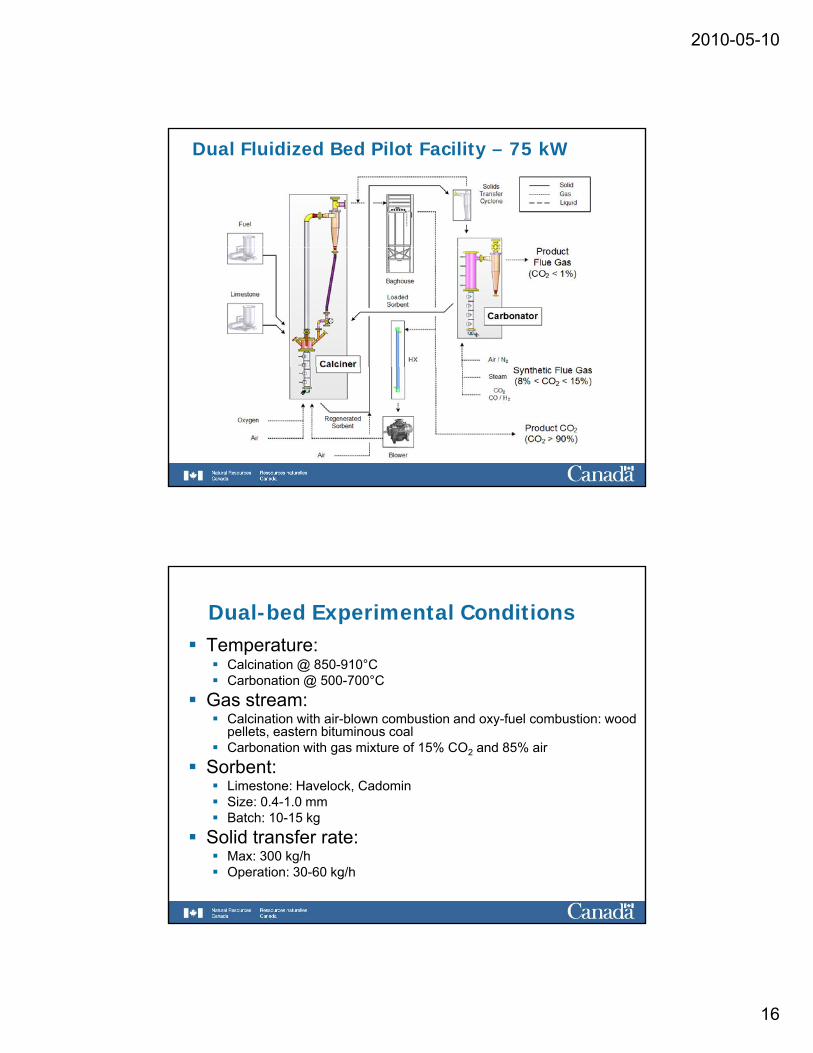
Dual Fluidized Bed Pilot Facility – 75 kW
Dual-bed Experimental ConditionsTemperature:
Calcination @ 850-910°CCarbonation @ 500-700°CC @ 500 00 C
Gas stream: Calcination with air-blown combustion and oxy-fuel combustion: wood pellets, eastern bituminous coalCarbonation with gas mixture of 15% CO2 and 85% air
Sorbent:Limestone: Havelock, CadominSize: 0 4-1 0 mmSize: 0.4 1.0 mmBatch: 10-15 kg
Solid transfer rate:Max: 300 kg/hOperation: 30-60 kg/h
2010-05-10
17
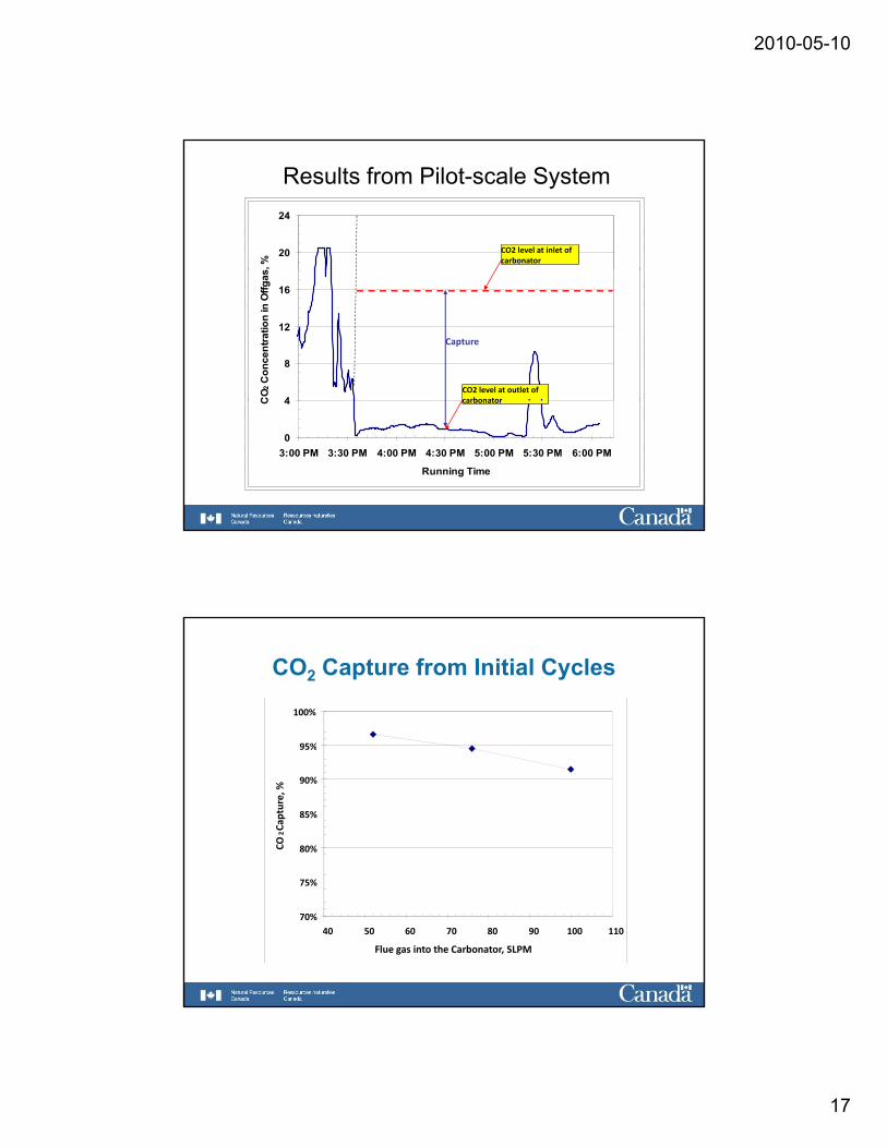
Results from Pilot-scale System
20
24
s, %
CO2 level at inlet of carbonator
4
8
12
16
CO 2
Con
cent
ratio
n in
Offg
as
Capture
CO2 level at outlet of carbonator
0
4
3:00 PM 3:30 PM 4:00 PM 4:30 PM 5:00 PM 5:30 PM 6:00 PM
Running Time
C carbonator
CO2 Capture from Initial Cycles
95%
100%
80%
85%
90%
95%
CO2Ca
pture, %
70%
75%
40 50 60 70 80 90 100 110
Flue gas into the Carbonator, SLPM
2010-05-10
18
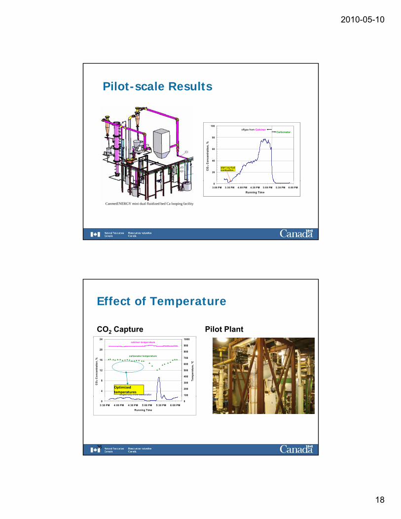
Pilot-scale Results
20
40
60
80
100
CO
2 C
once
ntra
tion,
%
offgas from CalcinerCarbonator
start oxy-fuel combustion
20
40
60
80
100
CO
2 C
once
ntra
tion,
%
offgas from CalcinerCarbonator
start oxy-fuel combustion
03:00 PM 3:30 PM 4:00 PM 4:30 PM 5:00 PM 5:30 PM 6:00 PM
Running Tim e
03:00 PM 3:30 PM 4:00 PM 4:30 PM 5:00 PM 5:30 PM 6:00 PM
Running Tim e
CanmetENERGY mini dual fluidized bed Ca looping facility
Effect of Temperature
CO2 Capture Pilot Plant
4
8
12
16
20
24
CO
2 Con
cent
ratio
n, %
100
200
300
400
500
600
700
800
900
1000
Tem
pera
ture
, °C
calciner temperature
carbonator temperature
offgas CO2 from carbonator
Optimized temperatures
03:30 PM 4:00 PM 4:30 PM 5:00 PM 5:30 PM 6:00 PM
Running Time
0
36
2010-05-10
19
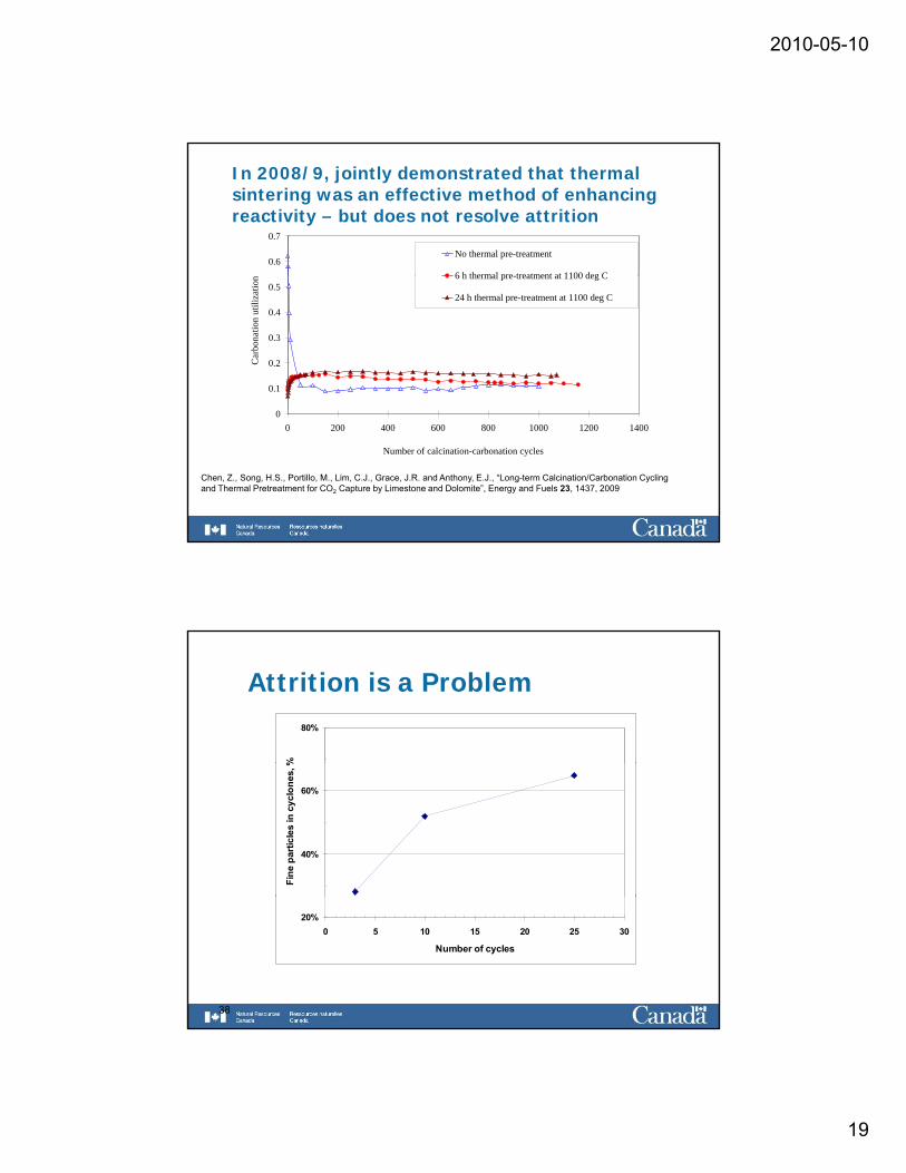
In 2008/9, jointly demonstrated that thermal sintering was an effective method of enhancing reactivity – but does not resolve attrition
0.6
0.7
No thermal pre-treatment
6 h thermal pre treatment at 1100 deg C
0.1
0.2
0.3
0.4
0.5
Car
bona
tion
utili
zatio
n 6 h thermal pre-treatment at 1100 deg C
24 h thermal pre-treatment at 1100 deg C
00 200 400 600 800 1000 1200 1400
Number of calcination-carbonation cycles
Chen, Z., Song, H.S., Portillo, M., Lim, C.J., Grace, J.R. and Anthony, E.J., “Long-term Calcination/Carbonation Cycling and Thermal Pretreatment for CO2 Capture by Limestone and Dolomite”, Energy and Fuels 23, 1437, 2009
Attrition is a Problem80%
%
40%
60%
Fine
par
ticle
s in
cyc
lone
s, %
38
20%0 5 10 15 20 25 30
Number of cycles
2010-05-10
20
80%
100%tio
n
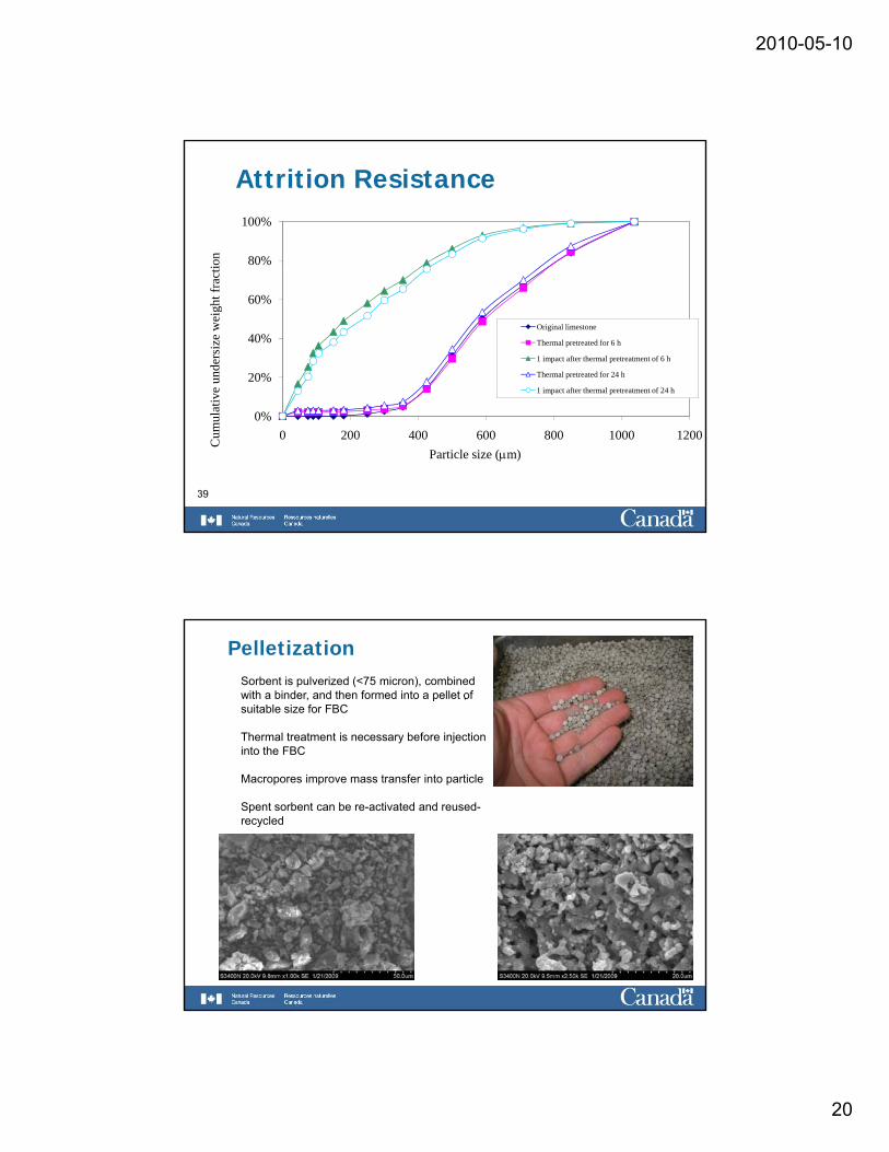
Attrition Resistance
20%
40%
60%
ive
unde
rsiz
e w
eigh
t fra
ct
Original limestone
Thermal pretreated for 6 h
1 impact after thermal pretreatment of 6 h
Thermal pretreated for 24 h
1 impact after thermal pretreatment of 24 h
0%0 200 400 600 800 1000 1200C
umul
ati
Particle size (μm)
39
Pelletization
.Sorbent is pulverized (<75 micron), combined with a binder, and then formed into a pellet of suitable size for FBC
Thermal treatment is necessary before injection into the FBCinto the FBC
Macropores improve mass transfer into particle
Spent sorbent can be re-activated and reused-recycled
2010-05-10
21
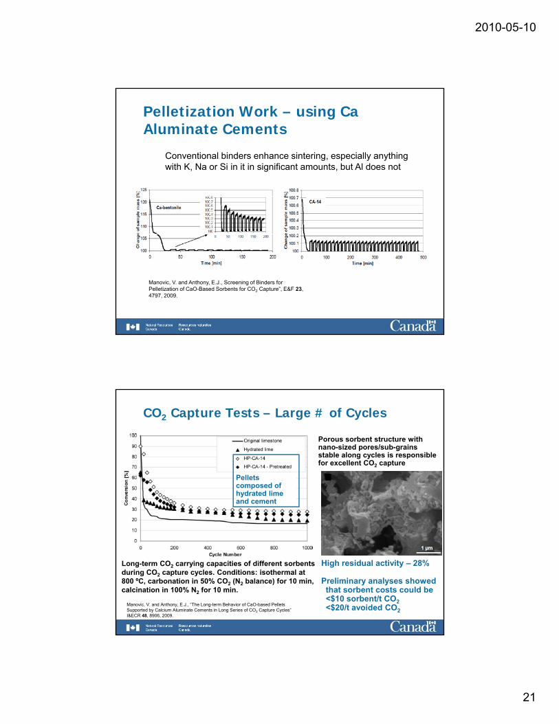
Pelletization Work – using Ca Aluminate Cements
Conventional binders enhance sintering, especially anything with K, Na or Si in it in significant amounts, but Al does not, g ,
Manovic, V. and Anthony, E.J., Screening of Binders for Pelletization of CaO-Based Sorbents for CO2 Capture”, E&F 23, 4797, 2009.
CO2 Capture Tests – Large # of Cycles
Porous sorbent structure with nano-sized pores/sub-grains stable along cycles is responsible for excellent CO2 capture
Pellets composed of hydrated lime and cement
Long-term CO2 carrying capacities of different sorbents during CO2 capture cycles. Conditions: isothermal at 800 ºC, carbonation in 50% CO2 (N2 balance) for 10 min, calcination in 100% N2 for 10 min.
High residual activity – 28%
Preliminary analyses showedthat sorbent costs could be<$10 sorbent/t CO2<$20/t avoided CO2
Manovic, V. and Anthony, E.J., “The Long-term Behavior of CaO-based Pellets Supported by Calcium Aluminate Cements in Long Series of CO2 Capture Cycles” I&ECR 48, 8906, 2009.
2010-05-10
22
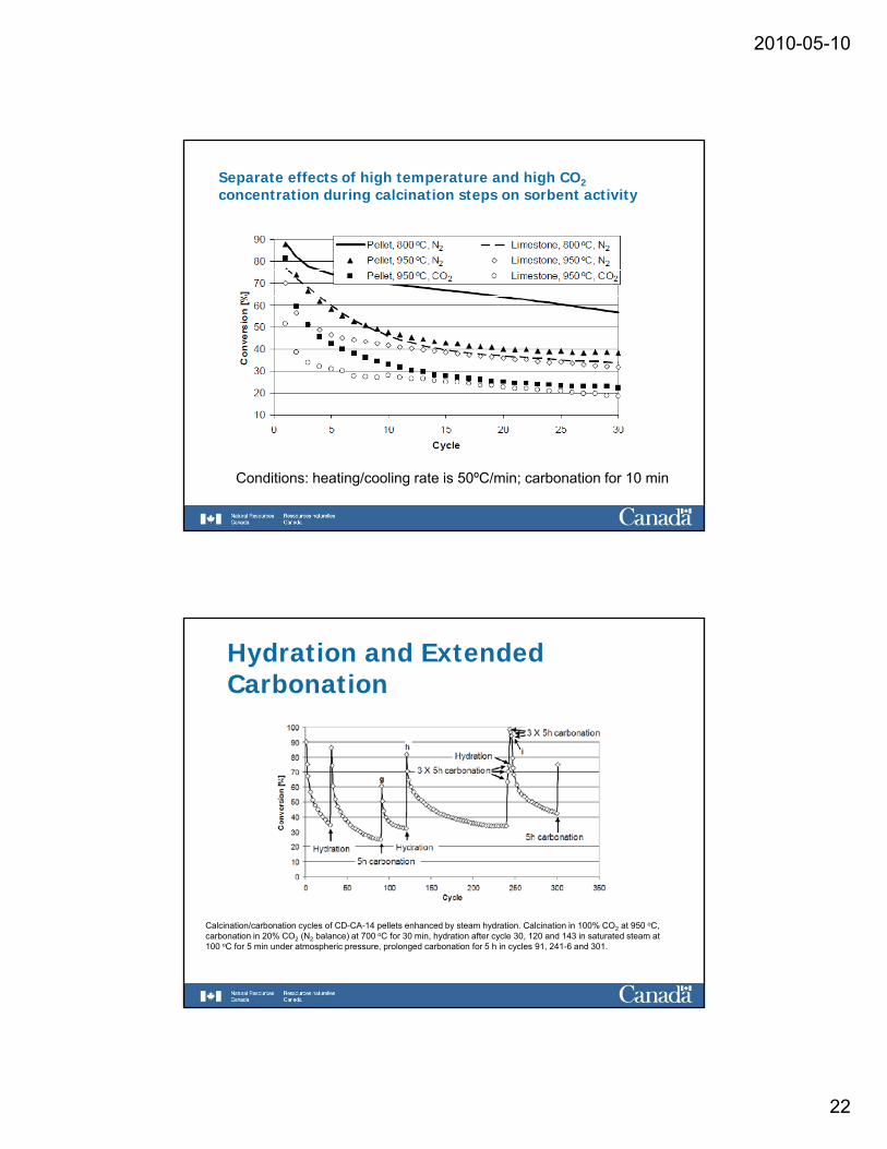
Separate effects of high temperature and high CO2concentration during calcination steps on sorbent activity
Conditions: heating/cooling rate is 50ºC/min; carbonation for 10 min
Hydration and Extended Carbonation
Calcination/carbonation cycles of CD-CA-14 pellets enhanced by steam hydration. Calcination in 100% CO2 at 950 oC, carbonation in 20% CO2 (N2 balance) at 700 oC for 30 min, hydration after cycle 30, 120 and 143 in saturated steam at 100 oC for 5 min under atmospheric pressure, prolonged carbonation for 5 h in cycles 91, 241-6 and 301.
2010-05-10
23
60708090
100
n [%
]
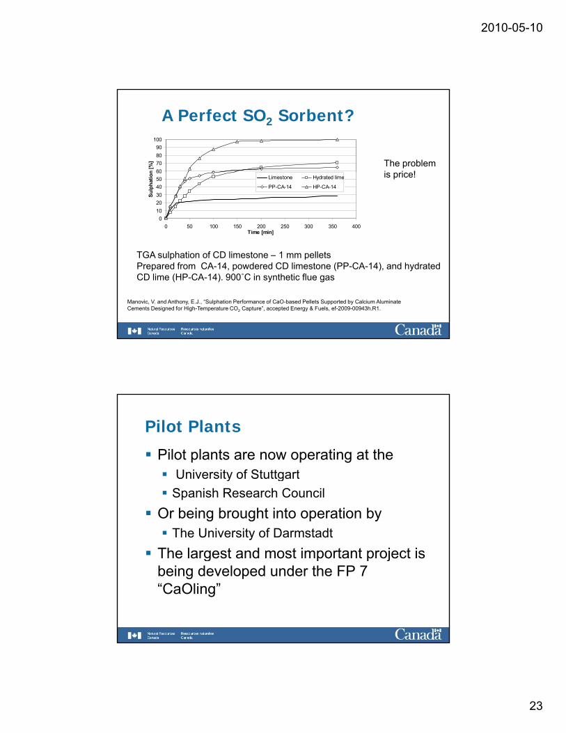
A Perfect SO2 Sorbent?
The problemi i !
0102030405060
0 50 100 150 200 250 300 350 400Time [min]
Sulp
hatio
n
Limestone Hydrated lime
PP-CA-14 HP-CA-14
TGA sulphation of CD limestone – 1 mm pellets
is price!
TGA sulphation of CD limestone – 1 mm pelletsPrepared from CA-14, powdered CD limestone (PP-CA-14), and hydrated CD lime (HP-CA-14). 900˚C in synthetic flue gas
Manovic, V. and Anthony, E.J., “Sulphation Performance of CaO-based Pellets Supported by Calcium Aluminate Cements Designed for High-Temperature CO2 Capture”, accepted Energy & Fuels, ef-2009-00943h.R1.
Pilot Plants
Pilot plants are now operating at theUniversity of StuttgartUniversity of StuttgartSpanish Research Council
Or being brought into operation byThe University of Darmstadt
The largest and most important project is g p p jbeing developed under the FP 7 “CaOling”
2010-05-10
24
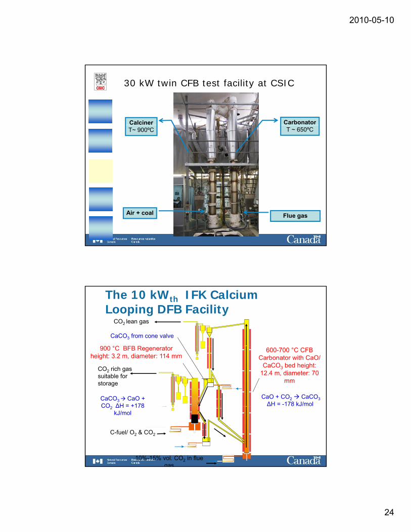
30 kW twin CFB test facility at CSIC
Calciner CarbonatorT~ 900ºC T ~ 650ºC
Air + coal Flue gas
The 10 kWth IFK Calcium Looping DFB Facility
900 °C BFB R t
CaCO3 from cone valve
CO2 lean gas
600-700 °C CFB Carbonator with CaO/
CaCO3 bed height: 12.4 m, diameter: 70
mm
900 °C BFB Regeneratorheight: 3.2 m, diameter: 114 mm
CaCO3 CaO + CO2 ΔH = +178
CO2 rich gas suitable for storage
CaO + CO2 CaCO3 ΔH = -178 kJ/mol
10%-15% vol. CO2 in flue gas
CO2 ΔH +178 kJ/mol
C-fuel/ O2 & CO2
2010-05-10
25
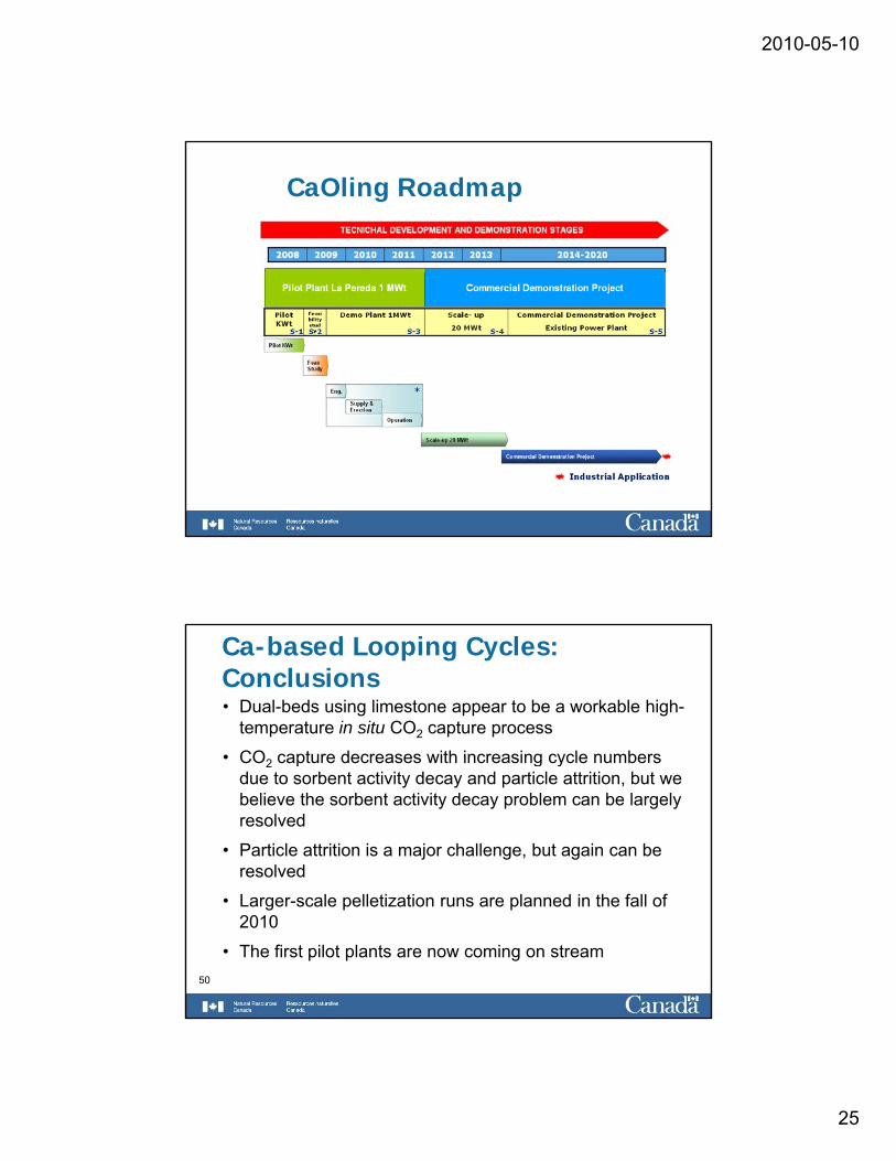
CaOling Roadmap
Ca-based Looping Cycles: Conclusions• Dual-beds using limestone appear to be a workable high-
temperature in situ CO2 capture process
• CO capture decreases with increasing cycle numbers• CO2 capture decreases with increasing cycle numbers due to sorbent activity decay and particle attrition, but we believe the sorbent activity decay problem can be largely resolved
• Particle attrition is a major challenge, but again can be resolved
50
• Larger-scale pelletization runs are planned in the fall of 2010
• The first pilot plants are now coming on stream
2010-05-10
26
Bibliography
Blamey, J., Anthony, E.J., Wang, J. and Fennell, P., “The Calcium Looping Cycle for Large-Scale CO2 Capture”, Progress in Energy and Combustion Science 36, 260-279, 2010.
THANK YOU FOR YOUR ATTENTIONTHANK YOU FOR YOUR ATTENTION.
QUESTIONS?
E-mail:[email protected] (Ben Anthony)
2010-05-10
27
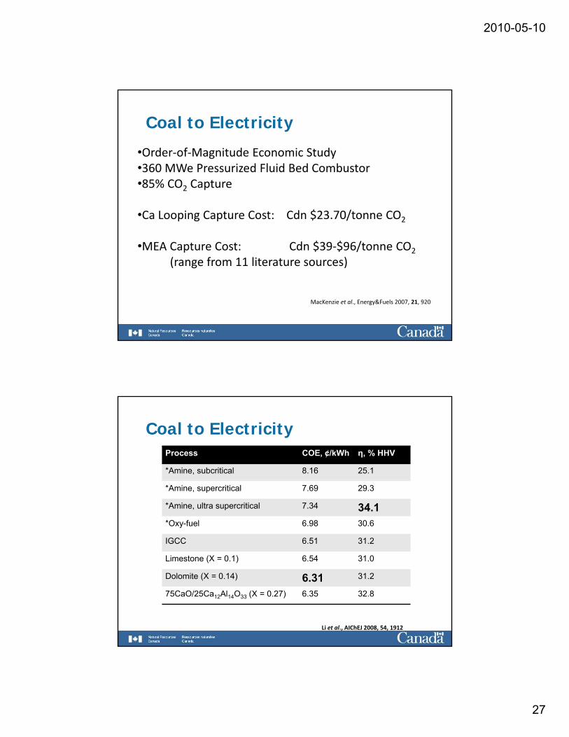
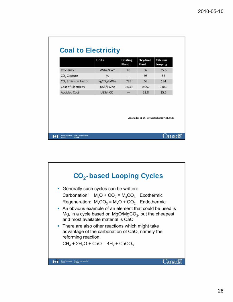
Coal to Electricity
•Order‐of‐Magnitude Economic Study•360 MWe Pressurized Fluid Bed Combustor•85% CO2 Capture
•Ca Looping Capture Cost: Cdn $23.70/tonne CO2
•MEA Capture Cost: Cdn $39‐$96/tonne CO2( f l )(range from 11 literature sources)
MacKenzie et al., Energy&Fuels 2007, 21, 920
Coal to ElectricityProcess COE, ¢/kWh η, % HHV
*Amine, subcritical 8.16 25.1
*Amine, supercritical 7.69 29.3
*Amine, ultra supercritical 7.34 34.1*Oxy-fuel 6.98 30.6
IGCC 6.51 31.2
Limestone (X = 0.1) 6.54 31.0
Dolomite (X = 0.14) 6.31 31.2
75CaO/25Ca12Al14O33 (X = 0.27) 6.35 32.8
Li et al., AIChEJ 2008, 54, 1912
2010-05-10
28
Coal to ElectricityUnits Existing
PlantOxy‐fuel Plant
Calcium Looping
Efficiency kWhe/kWh 43 32 35.6Efficiency kWhe/kWh 43 32 35.6
CO2 Capture % ‐‐‐ 95 86
CO2 Emission Factor kgCO2/kWhe 795 53 134
Cost of Electricity US$/kWhe 0.039 0.057 0.049
Avoided Cost US$/t CO2 ‐‐‐ 23.8 15.5
Abanades et al., EnvSciTech 2007,41,5523
CO2-based Looping Cycles
Generally such cycles can be written:Carbonation: MxO + CO2 = MxCO3 ExothermicCarbonation: MxO CO2 MxCO3 ExothermicRegeneration: MxCO3 = MxO + CO2 EndothermicAn obvious example of an element that could be used is Mg, in a cycle based on MgO/MgCO3, but the cheapest and most available material is CaOThere are also other reactions which might take advantage of the carbonation of CaO namely the
56
advantage of the carbonation of CaO, namely the reforming reaction:CH4 + 2H2O + CaO = 4H2 + CaCO3
Energy Systemsand TechnologyProf. Dr.-Ing. B. Epple
Petersenstrasse 3064287 Darmstadt / GermanyPhone: +49 6151 16 2191www.est.tu-darmstadt.de
TU Darmstadt
Chair for Energy Systems and Technology
CCS equipment
1
Energy Systemsand TechnologyProf. Dr.-Ing. B. Epple
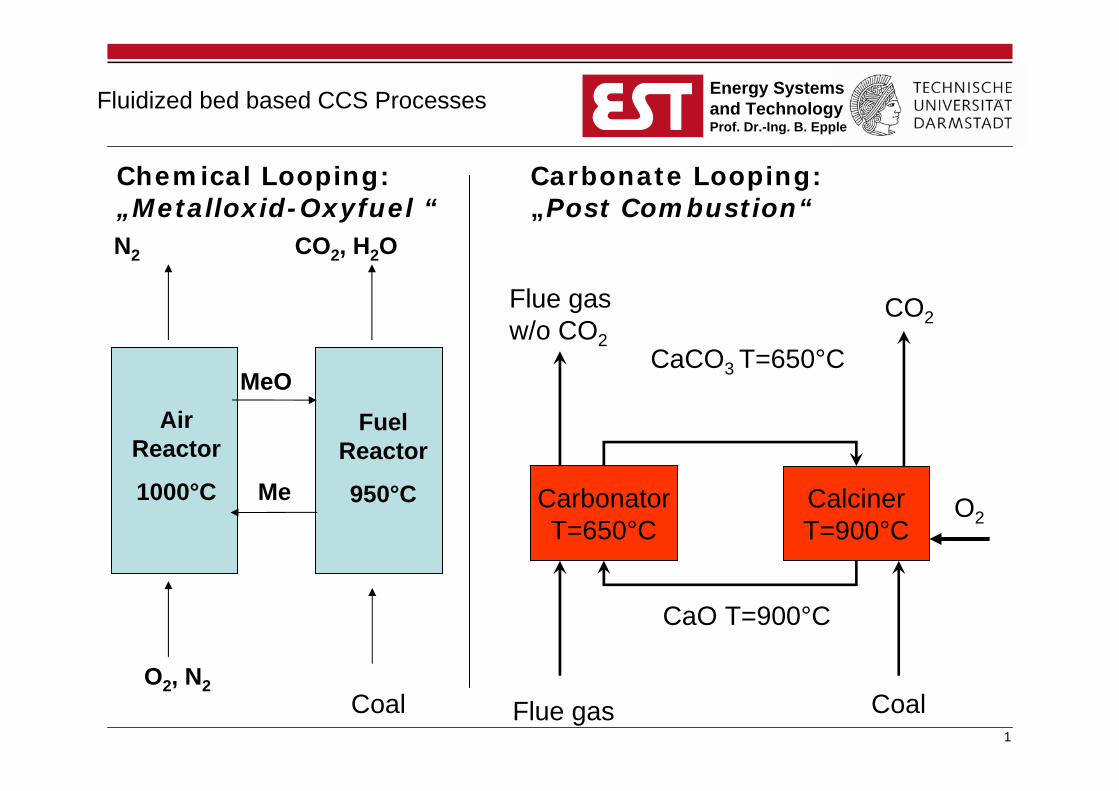
Carbonate Looping:„Post Combustion“
CarbonatorT=650°C
CalcinerT=900°C
Flue gas
Flue gas w/o CO2
CaCO3 T=650°C
CaO T=900°C
Coal
CO2
Air Reactor
1000°C
Fuel Reactor
950°CMe
MeO
O2, N2
N2 CO2, H2O
Chemical Looping:„Metalloxid-Oxyfuel “
O2
Fluidized bed based CCS Processes
Coal
2
Energy Systemsand TechnologyProf. Dr.-Ing. B. Epple
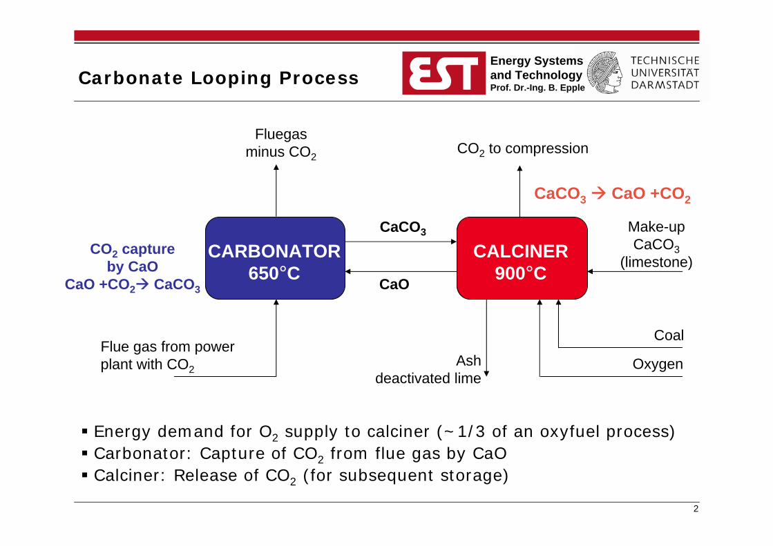
Carbonate Looping Process
CaO
CaCO3
CO2 to compressionFluegas
minus CO2
Flue gas from power plant with CO2
Ashdeactivated lime
Make-up CaCO3
(limestone)
Oxygen
Coal
CARBONATOR650°C
CALCINER900°C
CO2 captureby CaO
CaO +CO2 CaCO3
Energy demand for O2 supply to calciner (~1/3 of an oxyfuel process) Carbonator: Capture of CO2 from flue gas by CaO Calciner: Release of CO2 (for subsequent storage)
CaCO3 CaO +CO2
3
Energy Systemsand TechnologyProf. Dr.-Ing. B. Epple
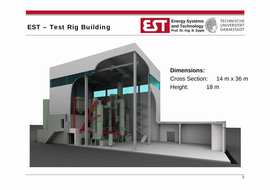
EST – Test Rig Building
Dimensions:Cross Section: 14 m x 36 mHeight: 18 m
4
Energy Systemsand TechnologyProf. Dr.-Ing. B. Epple
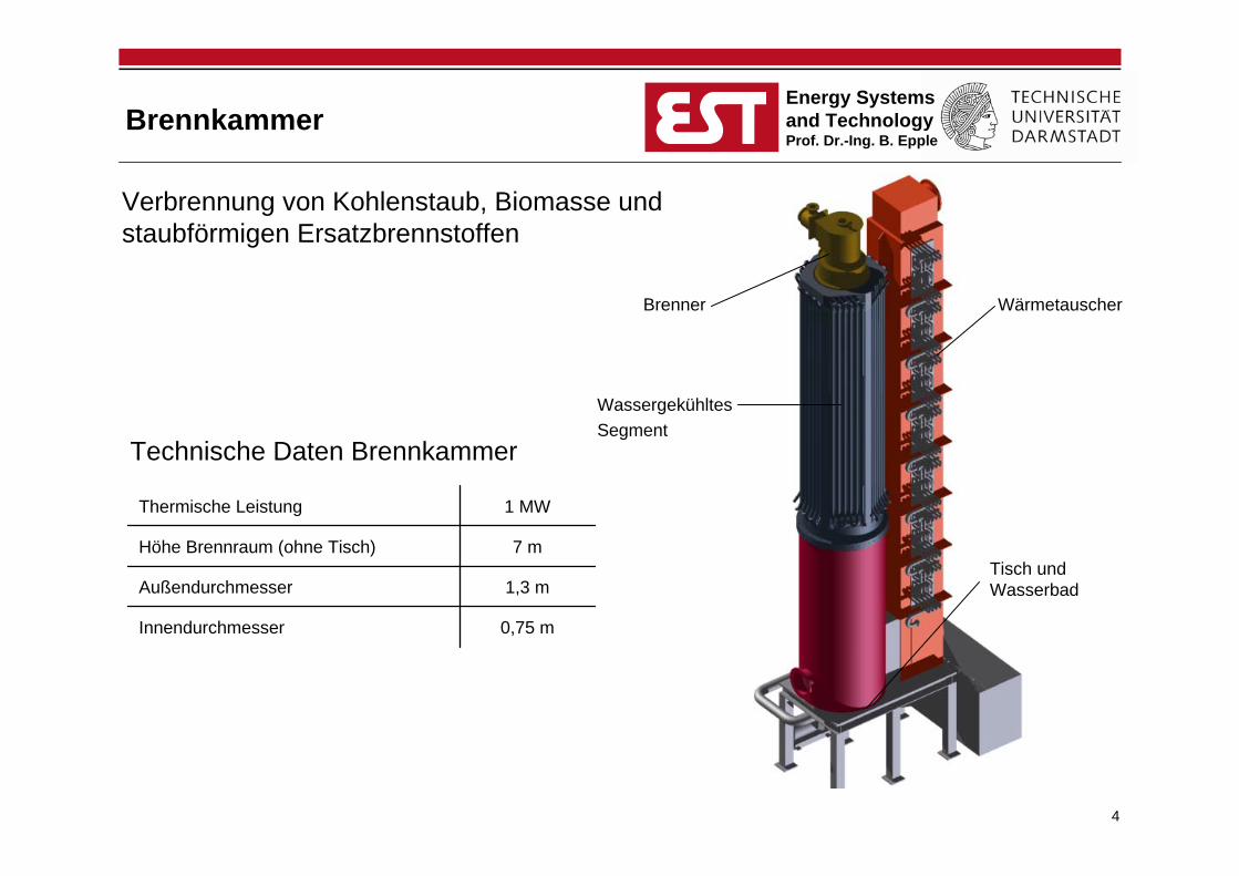
Brennkammer
Wärmetauscher
WassergekühltesSegment
Tisch und Wasserbad
Technische Daten Brennkammer
Verbrennung von Kohlenstaub, Biomasse und staubförmigen Ersatzbrennstoffen
0,75 mInnendurchmesser
1,3 mAußendurchmesser
7 mHöhe Brennraum (ohne Tisch)
1 MWThermische Leistung
Brenner
5
Energy Systemsand TechnologyProf. Dr.-Ing. B. Epple
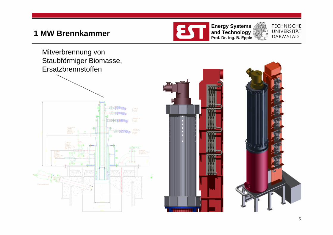
1 MW Brennkammer
Mitverbrennung von Staubförmiger Biomasse, Ersatzbrennstoffen
6
Energy Systemsand TechnologyProf. Dr.-Ing. B. Epple
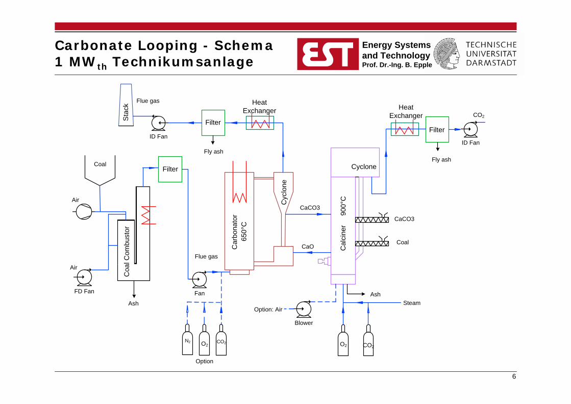
Carbonate Looping - Schema 1 MWth Technikumsanlage
FilterFilter
Filter Cyclone
Cyc
lone
Cal
cine
r
Car
bona
tor
Coa
l Com
bust
or
Heat Exchanger
Heat Exchanger
Air
Sta
ck
650°
C
900°
C
FD Fan Fan
ID Fan
Blower
ID Fan
Coal
Air
Ash
Flue gas
Flue gas
Fly ash
CaCO3
CaO
Option: Air
O2
CaCO3
Coal
CO2
Ash
CO2
Fly ash
Steam
CO2N2
Option
O2
7
Energy Systemsand TechnologyProf. Dr.-Ing. B. Epple
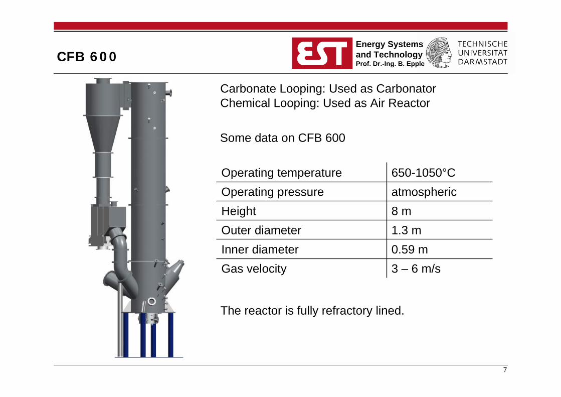
CFB 600
Carbonate Looping: Used as CarbonatorChemical Looping: Used as Air Reactor
0.59 mInner diameter3 – 6 m/sGas velocity
1.3 mOuter diameter8 mHeightatmosphericOperating pressure650-1050°COperating temperature
Some data on CFB 600
The reactor is fully refractory lined.
8
Energy Systemsand TechnologyProf. Dr.-Ing. B. Epple
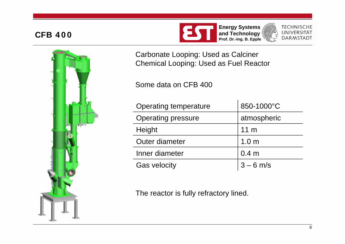
CFB 400
Carbonate Looping: Used as CalcinerChemical Looping: Used as Fuel Reactor
0.4 mInner diameter3 – 6 m/sGas velocity
1.0 mOuter diameter11 mHeightatmosphericOperating pressure850-1000°COperating temperature
Some data on CFB 400
The reactor is fully refractory lined.
9
Energy Systemsand TechnologyProf. Dr.-Ing. B. Epple
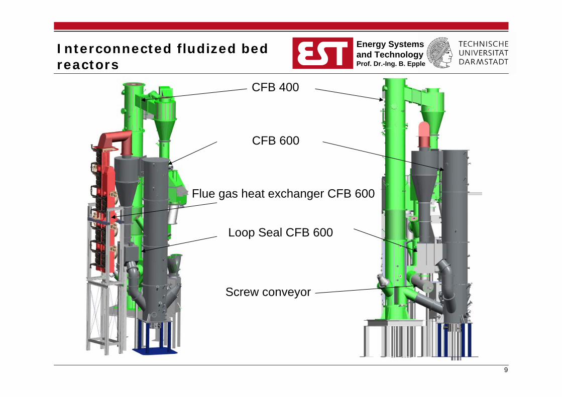
Interconnected fludized bedreactors
CFB 400
CFB 600
Flue gas heat exchanger CFB 600
Loop Seal CFB 600
Screw conveyor
Recommended


![Alstom’s [GE] Chemical Looping Combustion Technology ......Imagination at work Alstom’s [GE] Chemical Looping Combustion Technology with CO2 Capture for New and Existing Coal-fired](https://img.pdfslide.us/doc/110x75/60fbc9baac9da0424a530e18/alstomas-ge-chemical-looping-combustion-technology-imagination-at-work.jpg)