Installation Instructions
Connect UltraLite
Connection Centre
CDW10U2UL
CDW10U2C
by Honeywell
WARNING 230V a.c.
The connections to this equipment should be made by a suitably qualified person in accordance with the current wiring regulations.
It is strongly recommended to use Ex-Or latching type connectors.
The unit must be earthed.
Connect UltraLite provides an efficient way to interconnect presence detectors and luminaires using industry standard connectors. One or two detectors can be connected to up to ten luminaires depending upon the configuration required.
Dedicated UltraLite detectors are available as well as a range of Plugs and Leads to convert LightSpot HD sensors for use with the UltraLite CD Box (see back page for part numbers).
Electrical Connections
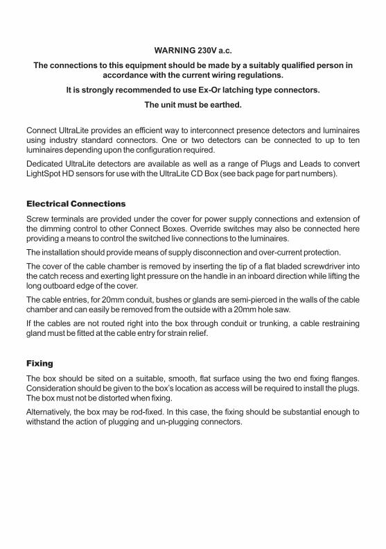
Screw terminals are provided under the cover for power supply connections and extension of the dimming control to other Connect Boxes. Override switches may also be connected here providing a means to control the switched live connections to the luminaires.
The installation should provide means of supply disconnection and over-current protection.
The cover of the cable chamber is removed by inserting the tip of a flat bladed screwdriver into the catch recess and exerting light pressure on the handle in an inboard direction while lifting the long outboard edge of the cover.
The cable entries, for 20mm conduit, bushes or glands are semi-pierced in the walls of the cable chamber and can easily be removed from the outside with a 20mm hole saw.
If the cables are not routed right into the box through conduit or trunking, a cable restraining gland must be fitted at the cable entry for strain relief.
Fixing
The box should be sited on a suitable, smooth, flat surface using the two end fixing flanges. Consideration should be given to the box’s location as access will be required to install the plugs. The box must not be distorted when fixing.
Alternatively, the box may be rod-fixed. In this case, the fixing should be substantial enough to withstand the action of plugging and un-plugging connectors.

Factory Configuration
When the unit is shipped, the dimming control and switched lives are linked in the terminal space. LK2 and LK3 MUST BE REMOVED if two detectors with dimming outputs are connected to the box. (LK1 must also be removed when using analogue detectors.)
A red indicator in the connection chamber indicates that power is present.
Connections are made as illustrated to the left. Two spare terminals are provided for termination purposes.
Live (Lin) is routed to the two detector connectors (A1 and B1).
Maintained Live (ML) is routed to the ten luminaire connectors, A2-A6 and B2-B6.
SWA is the switched live output from a detector connected to A1.
SWB is the switched live output from a detector connected to B1.
LK1 is a common connection between the switched live from each detector position. It must be removed to separate the luminaires into two groups.
Dimming Control TerminalsThe Dimming Control signals from each detector to its group of luminaires are accessible at terminals under the connection chamber cover. Links are factory fitted to join the two groups on to one detector.
Lin
MLMAINTAINED LIVEInternally connected to A2-6 and B2-6
LIVE INPUT Internally connected to A1 and B1Lin internally linked
MAINS INPUT: 230V 50HzMax load on any single outlet: 6AMax total load: 16Atc: 5 - 50 CNo user-serviceable parts inside
EARTH INPUT Protected Earth E terminals internally linked
GROUP A(Connect wall switcheshere if not using plug-in detectors)GROUP B
Manual input OneSwitch Group A(Only when used with compatible detectors)
Manual input OneSwitch Group B
LK1 External Link
Spare
Spare
Spare terminals have no internal connection
AB
B+A+
__ LK2
LK3
External Links
Dimming ControlNOTE: Links 2 and 3 MUST BE REMOVED when using two dimming detectors
PB-A
PB-B
SWA
SWB
N
E
E
Lin

Detector Connection
There are two detector connection positions on each box. The detector is connected by a flying lead and GST18/7 plug.
Luminaire Connection
There are ten luminaire outlets on each box. Each luminaire is connected by a flying lead and GST18/6 plug.
Ensure maxdetector load is not exceeded
Dimming control See Detector Data
for allowed ballast load
Switched Live
Neutral
Maintained Live
+
-
Max load 6Aper output
Dimming control - Detector output
Switched Live
NeutralLive - Supply to detector
+
-
Push Button input to detector
Simple schematic showing connection information (including two spare terminals):
Detector B
Maintained Live
Live In
Live InNeutralEarth
Earth
SWA
SWB
Push Button A
Push Button B
SpareSpare
Detector A
TOP HALF
BOTTOM HALF
Group A
Group B
If sockets A1 and B1 are not occupied by a presence detector, those sockets may be used for luminaires. The plug, however, will need to be 7-pole and wired appropriately.
A+
A-
B+
B-

Connection Examples
Single Detector with 10 Luminaires
(For load information, see Note under Technical Data)
A6 A5 A4 A3 A2 A1
Up to 10 luminaires
De
tect
or
B6 B5 B4 B3 B2 Not used
LK2
LK3
B-
B+
A-
A+
E
N
L
E
L
ML
SWB
SWA
PB-B
PB-A
No connection
Manualcontrol
LK1 is not required for analogue or switching type of detectors
LK1
RemoveLinks
LK2 and LK3
Two Detectors
(For load information, see Note under Technical Data)
LK1 is not required for analogue or switching type of detectors
E
N
L
E
L
ML
SWB
SWA
PB-B
PB-A
De
tect
or
De
tect
or
GROUP B
B6 B5 B4 B3 B2 B1
GROUP A
B-
B+
A-
A+
A6 A5 A4 A3 A2 A1
LK1
Manualcontrol
K
K
Emergency Test Key-Switch*
Emergency Test Key-Switch*
* Emergency Test Key-Switch wired to remove mains supply from all of the Connection Centre
* Emergency Test Key-Switch wired to remove emergency permanent feed only
230V Supply
230V Supply

Distribution Unit with Mains-Based ‘OneTouch’ Dimming(for use with compatible Digital Ballasts)
A6 A5 A4 A3 A2 A1
Up to 12 luminaires
B6 B5 B4 B3 B2 B1
A-
A+
B-
B+
E
N
L
E
L
ML
SWB
SWA
PB-B
PB-A
Distribution Unit with External Low-Voltage Dimming Control
Up to 6 luminaires
B6 B5 B4 B3 B2 B1
A6 A5 A4 A3 A2 A1
Up to 6 luminaires
E
ML
E
N
L
E
L
ML
SWB
SWA
PB-B
PB-A
N
From Supply Isolator
L
LK1
LK1
no connection
no connection
A-
A+
B-
B+
FromExternalDimmingControl
RemoveLinks
LK2 and LK3
E
ML
N
From Supply Isolator
L
Manualcontrol
Notes: (i) The dimming control connections are mains rated.
(ii) Unit must not be used with multi-phase connections.
(iii) Mains-based dimming must not be used in conjunction with Ex-Or’s range of presence detectors.
no connection
no connection
no connection
no connection
no connection
no connection
no connection

OPERATING VOLTAGE: 230V 50Hz (UK & Europe)
PRODUCT RATING/RECOMMENDED CIRCUIT PROTECTION: 16 Amps
MAXIMUM LOAD PER OUTLET: 6 Amps*
MAXIMUM TOTAL LOAD: 16 Amps*2 2SUPPLY TERMINAL CAPACITY: 6.0mm (2 x 2.5mm )
2DIMMING TERMINAL CAPACITY: 4.0mm
CASE MATERIAL: Polycarbonate
CASE FINISH: Lightly textured light grey
WEIGHT: 1.27kg
Technical Data
H
F
D2
W
Height (H) = 50mm (108mm including plug and lead)
Width (W) = 315mm (361mm including mounting feet)
Depth (D) = 205mm
Fixing Centres (F) = 340mm
Weight = 1.85 kg
Dimensions
* Note: These specifications relate to the product when used as a simple wiring device. When mains-switching presence detectors are used in conjunction with this equipment, it is the presence detectors which will normally dictate the maximum load. It is important to check, and not exceed, the specification of the current-switching presence detectors, which will typically be around 6 Amps.

W5007J
At the end of their useful life the packaging and product should be disposed of via a suitable recycling centre.Do not dispose of with normal household waste.Do not burn.
Auxiliary Items
Luminaire Leads:
CPWL633 Connect 3m Luminaire Connector - 6-pin/3-core, Wieland GST 18/6 c/w Ex-Or locking mechanism
CPWL635 Connect 5m Luminaire Connector - 6-pin/3-core, Wieland GST 18/6 c/w Ex-Or locking mechanism
CPWL653 Connect 3m Luminaire Connector - 6-pin/5-core, Wieland GST 18/6 c/w Ex-Or locking mechanism
CPWL655 Connect 5m Luminaire Connector - 6-pin/5-core, Wieland GST 18/6 c/w Ex-Or locking mechanism
Emergency Luminaire Leads:
CPWL643 Connect 3m Luminaire Connector - 6-pin/4-core, Wieland GST 18/6 c/w Ex-Or locking mechanism
CPWL645 Connect 5m Luminaire Connector - 6-pin/4-core, Wieland GST 18/6 c/w Ex-Or locking mechanism
CPWL663 Connect 3m Luminaire Connector - 6-pin/6-core, Wieland GST 18/6 c/w Ex-Or locking mechanism
CPWL665 Connect 5m Luminaire Connector - 6-pin/6-core, Wieland GST 18/6 c/w Ex-Or locking mechanism
Plugs with Latching Shell
CPWL6 For luminaire: GST18/6 6-pole male plug with Ex-Or locking mechanism (complete)
CPWL7 For detector: GST 18/7 7-pole Wieland GST male plug with Ex-Or locking mechanism (complete)
Latching Shell only
CPWL6S For luminaire: GST-6 Ex-Or plug-locking mechanism (shell only)
CPWL7S For detector: GST-7 Ex-Or locking mechanism (shell only)
Leads for the connection of LightSpot HD sensors:
LSHDDLW753 LightSpot HD Dimming lead, Wieland 7-pin/5-core - 3 metre
LSHDDLW755 LightSpot HD Dimming lead, Wieland 7-pin/5-core - 5 metre
LSHDSLW753 LightSpot HD Switching lead, Wieland 7-pin/5-core - 3 metre
LSHDSLW755 LightSpot HD Switching lead, Wieland 7-pin/5-core - 5 metre
LSHDDSLW763 LightSpot HD Dimming and Switching lead, Wieland 7-pin/6-core - 3 metre
LSHDDSLW765 LightSpot HD Dimming and Switching lead, Wieland 7-pin/6-core - 5 metre
LSHDQBL226 LightSpot HD QuickLink Bus lead, 2-pin/2-core - 6 metre
LSHDQBL2210 LightSpot HD QuickLink Bus lead, 2-pin/2-core - 10 metre
Connect UltraLite Detectors:
MS1100PFSWCWL7 Connect Bronze Series LightSpot PIR with photocell - slimline flush
MS1200PFSWCWL7 Connect Silver Series LightSpot PIR with photocell - slimline flush
MS2000DFCWL7 Connect Silver Series LightSpot PIR for DSI ballasts - flush
MS2000DALIFCWL7 Connect Silver Series LightSpot PIR for DALI ballasts - flush
MLS2421DFCWL7* Connect Gold Series LightSpot Microwave dual-output for DSI ballasts - flush
MLS2421DALIFCWL7* Connect Series LightSpot Microwave dual-output for DALI ballasts - flush
MLS2021DFDFCWL7* Connect Gold Series LightSpot PIR dual-output for DSI ballasts - flush
MLS2021DALIFCWL7* Connect Gold Series LightSpot PIR dual-output for DALI ballasts - flush
Connect UltraLite detectors incorporate the facility for OneSwitch operation and are supplied with 3m cable and 7-way latching plug.
* These products do not have MLS functionality and cannot be connected using MLS cable.
Honeywell Ex-Or
St. Marks Court, North Street,
Horsham, West Sussex, RH12 1BW, UK.
Tel: +44 (0)1942 719229
Fax: +44 (0)1942 508753 Email: [email protected]
www.ex-or.com
Recommended


![Manuel MOTU Ultralite MK3 [Francais]](https://img.pdfslide.us/doc/110x75/55cf8de1550346703b8c3468/manuel-motu-ultralite-mk3-francais.jpg)