Bulletin 1492 I/O Wiring Conversion SystemsPLC-5 1771 to ControlLogix 1756Selection Guide

Bulletin 1492
I/O Wiring Conversion Systems - PLC-5 1771 to ControlLogix 1756
3Visit our website: www.ab.com/catalogs
Publication 1492-SG121C-EN-P
Product Overview
This I/O Conversion Module provides a fast and efficient method forconverting Bulletin 1771 I/O to Bulletin 1756 I/O. Risk due to wiringerrors is eliminated since the I/O Conversion is accomplishedwithout the removal of any field wires from the existing 1771 SwingArm. The existing 1771 Swing Arms fit directly onto the edgeconnector of the 1492 Conversion Modules. The 1492 Cables arepre-wired and have a connector for the 1492 Conversion Module onone end and a 1756 RTB (Removable Terminal Block) on the otherend. The I/O signals are routed through the 1492 ConversionModule and the 1492 Cable to the appropriate terminals on the1756 I/O module. Complete Wiring Diagrams for each 1771 I/OModule are shown.
A Conversion System consists of the following:
� Conversion Modules (Example Cat No: 1492-CM1771-LD001)
� Cables (Example Cat No: 1492-CONACAB005X)
� Conversion Mounting Assembly (Example Cat No: 1492-MUA4-A13-A17)
Bulletin 1492I/O Wiring Conversion System - 1771 to 1756
Table of Contents
ConversionModules andCables page 4
ProductSelection page 5
Specifications page 10ApproximateDimensions page 11WiringDiagrams page 19

Bulletin 1492
I/O Wiring Conversion Systems - Bulletin 1771 to ControlLogix 1756
4Visit our website: www.ab.com/catalogs
Publication 1492-SG121C-EN-P
Product Overview
0
1
2
3
4
5
6
7
8
9
10
11
Conversion Assembly Cover-PlateConversion Assembly Base-Plate
Conversion Mounting Assembly
The Conversion Modules are housed in a Conversion MountingAssembly Base Plate. This Base Plate has the same mountingfootprint and mounting holes as the 1771 chassis that it replaces.This eliminates the need to drill and tap new mounting holes in thecontrol cabinet.
The Conversion Mounting Assembly Cover Plate covers and protectsthe Conversion Modules while providing a place to mount the new1756 chassis. The Cover Plate has pre-drilled and tapped mountingholes allowing the new 1756 chassis to be mounted in severallocations – centered, right-justified or left-justified. This eliminatesthe need to drill and tap new mounting holes in the control cabinet.
Pre-wired 1492 CablesConversion Modules
The Bulletin 1492 I/O Wiring Conversion System virtually eliminates the time and risk associated with the normal “rip and replace” rewiringprocess by using Conversion Modules instead. The Conversion Modules provide the mating connections (edge connectors) to the specific1771 I/O Swing Arms. This allows the field wires to remain attached to the 1771 Swing Arm, eliminating the time and risk normallyassociated with converting from one I/O system to another. The I/O signals are routed through to a connector on the 1492 ConversionModule and through the 1492 pre-wired Cable to the appropriate terminals on the 1756 I/O module via the 1756 RTB (Removable TerminalBlock) on the other end of the 1492 pre-wired Cable.
Conversion Modules and Cables

Bulletin 1492
I/O Wiring Conversion Systems - PLC-5 1771 to ControlLogix 1756
5Visit our website: www.ab.com/catalogs
Publication 1492-SG121C-EN-P
Product Selection
Step 1: Determine the quantity of each type of 1771 I/O modules used in the 1771 I/O Chassis to be convertedStep 2: Select the applicable 1492 Conversion Modules from Table 2, Section IIIStep 3: Review the Max Slots for I/O and Chassis Width data from the Table 1 belowStep 4: Select a 1756 I/O Chassis which has enough I/O Slots
NOTE: (2) I/O slots are required in the 1756 Chassis for conversions where (1) 1771 I/O module converts to (2) 1756 I/O modulesStep 5: Select the 1492 Conversion Mounting Assembly which has enough Conversion Module slots.
NOTE: (2) Conversion Module slots are required in the 1492 Conversion Mounting Assembly for conversions where (2) 1771 I/O module convert to (1) 1756 I/O modules.
Step 6: The combined Depth of the 1492 Conversion Mounting Assembly with the 1756 Chassis mounted on top is 10.25 inches (Controller w/key) or 10.0 inches (Controller w/o key).
Step 7: Dimension drawings are included in the System Installation Manual that ships with the 1492 Conversion Mounting Assembly.
Bulletin 1492 Conversion Mounting Assembly
The 1492 Conversion Modules must be installed in a 1492 Conversion Mounting Assembly (see Table 1 below). A complete System Installation Manual ships with the 1492 Conversion Mounting Assembly.
Bulletin 1771 Chassis Bulletin 1756 Chassis Bulletin 1492 Conversion Mounting Assembly
Cat. No.
MaxSlotsforI/O
Chassis Width�in. (mm)
Cat. No.
MaxSlotsforI/O
Chassis Width in. (mm) Cat. No.
Max Slotsfor
ConversionModules
Chasis Width in. (mm)
Without PowerSupply
With PowerSupply
1771-A1B 4 9.01(229)
12.61(320)
1756-A4 3 10.35(263)
1492-MUA1B-A4-A7 4 9.01(229)
1756-A7 6 14.49(368)
1771-A2B 8 14.01(356)
17.61(447)
1756-A7 6 14.49(368)
1492-MUA2B-A7-A10 8 14.01(356)
1756-A10 9 19.02(483)
1771-A3B1 � 12 19.01(483)
1756-A10 9 19.02(483)
1492-MUA3-A10-A13 12 19.01(483)
1756-A13 12 23.15(588)
1771-A4B 16 24.01(610)
1756-A13 12 23.15(588)
1492-MUA4-A13-A17 16 24.01(610)
1756-A17 16 29.06(738)
� 1771-A3B is not listed as it is used for 19 inch wide instrumentation panels.�Notice that the 1756 Chassis Width sometimes exceeds the 1771 Chassis Width, with or without the Power Supply. The Cover-Plate of the 1492 Conversion
Mounting Assembly allows the 1756 Chassis to be Left justified, Right justified or Centered. A complete System Installation Manual ships with the 1492Conversion Mounting Assembly.

Bulletin 1492
I/O Wiring Conversion Systems - PLC-5 1771 to ControlLogix 1756
6Visit our website: www.ab.com/catalogs
Publication 1492-SG121C-EN-P
Product Selection
0
1
2
3
4
5
6
7
8
9
10
11
Table 2A - Digital Inputs
Step 1: In Column 1, find the Catalog Number of the 1771 Digital I/O module.
Step 2: In column 2, find the Catalog Number of the compatible 1756 Digital I/O module. In some cases more than one module exists.Review the matrix carefully and review the I/O module Installation Manuals to determine full compatibility.
Step 3: In column 3, find the Catalog Number of the 1492 Conversion Module.
Step 4: In column 4, find the Catalog Number of the 1492 Cable.
1 2 3 4
Bulletin 1771 Digital I/O Module � Qty.
Bulletin 1756 Digital I/O Module � Qty.
Bulletin 1492 Conversion Module Bulletin 1492 Cable �
Cat. No. OrderQty. Cat. No. Order
Qty.
1771-IA 2 1756-IA16 1 1492-CM1771-LD007 2 1492-C005005XE 1
1771-IA 2 1756-IA16 1 1492-CM1771-LD007 2 1492-C005005XE 1
1771-IAD 1 1756-IA16 1 1492-CM1771-LD001 1 1492-CONCAB005X 1
1771-IAD 1 1756-IH16I 1 1492-CM1771-LD002 1 1492-CONCAB005Y 1
1771-IAN 1 1756-IA32 1 1492-CM1771-LD003 1 1492-CONCAB005Z 1
1771-IB 2 1756-IB16 1 1492-CM1771-LD007 2 1492-C005005XE 1
1771-IBD 1 1756-IB16 1 1492-CM1771-LD001 1 1492-CONCAB005X 1
1771-IBN 1 1756-IB32 1 1492-CM1771-LD003 1 1492-CONCAB005Z 1
1771-IC 2 1756-IC16 1 1492-CM1771-LD007 2 1492-C005005XE 1
1771-ICD 1 1756-IC16 1 1492-CM1771-LD001 1 1492-CONCAB005X 1
1771-ID 2 1756-IA16I 1 1492-CM1771-LD007 2 1492-C005005XL 1
1771-ID01 2 1756-IM16I 1 1492-CM1771-LD003 2 1492-C005005XL 1
1771-ID16 1 1756-IA16I 1 1492-CM1771-LD004 1 1492-CONCAB005Y 1
1771-ID16 1 1756-IH16I 1 1492-CM1771-LD004 1 1492-CONCAB005Y 1
1771-IG 2 1756-IG16 1 � 1492-CM1771-LA003 2 1492-C005005XS 1
1771-IGD 1 1756-IG16 1 1492-CM1771-LD006 1 1492-CONCAB005X 1
1771-IH 2 1756-IC16 1 1492-CM1771-LD007 2 1492-C005005XE 1
1771-IM 2 1756-IM16I 1 1492-CM1771-LD007 2 1492-C005005XH 1
1771-IMD 1 1756-IM16I 1 1492-CM1771-LD002 1 1492-CONCAB005Y 1
1771-IN 2 1756-IN16 1 1492-CM1771-LD007 2 1492-C005005XE 1
1771-IND 1 1756-IN16 1 1492-CM1771-LD001 1 1492-CONCAB005X 1
1771-IND1 1 1756-IN16 1 1492-CM1771-LD001 1 1492-CONCAB005X 1
1771-IQ 2 1756-IB16I 1 1492-CM1771-LD007 2 Sink 1492-C005005XK 1
1771-IQ 2 1756-IB16I 1 1492-CM1771-LD014 2 Source 1492-C005005XJ 1
1771-IQ16 1 1756-IB16I 1 1492-CM1771-LD004 1 1492-CONCAB005Y 1
1771-IT 2 1756-IB16 1 1492-CM1771-LD007 2 1492-C005005XE 1
1771-IV 2 1756-IV16 1 1492-CM1771-LD014 2 1492-C005005XG 1
1771-IVN 1 1756-IV32 1 1492-CM1771-LD005 1 1492-CONCAB005Z 1
� The 005 in the Cat. No. indicates cable length of the Bulletin 1492 cable. The recommended length of 0.5 M is listed, additional lengths are listed below.1.0M Cable = 1492-CONCAB010_1.0M/1.0M Cable= 1492-C010010X_ 0.5M/1.0M Cable = 1492-C005010X_ 1.0M/0.5M Cable = 1492-C010005X_
� To understand any issues concerning I/O module compatibility refer to the conversion module wiring diagrams and the Installation Manuals for the specific I/Omodules involved (with particular attention to the specification and wiring instructions).
� These 1771 Digital I/O Modules use a Swing Arm that only mounts to these Analog I/O Conversion Modules, which will therefore be used to provide for these1771 Digital I/O conversions.
Bulletin 1492
I/O Wiring Conversion Systems - PLC-5 1771 to ControlLogix 1756
7Visit our website: www.ab.com/catalogs
Publication 1492-SG121C-EN-P
Product Selection
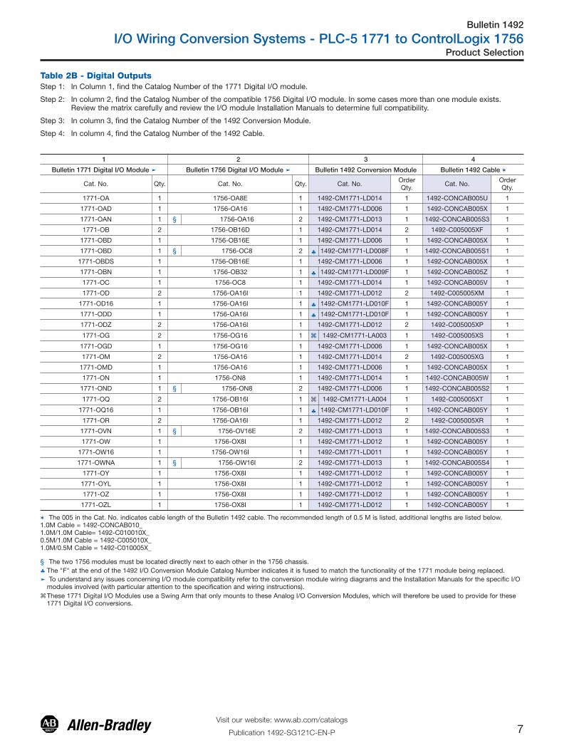
Table 2B - Digital Outputs
1 2 3 4
Bulletin 1771 Digital I/O Module � Bulletin 1756 Digital I/O Module � Bulletin 1492 Conversion Module Bulletin 1492 Cable �
Cat. No. Qty. Cat. No. Qty. Cat. No. OrderQty. Cat. No. Order
Qty.
1771-OA 1 1756-OA8E 1 1492-CM1771-LD014 1 1492-CONCAB005U 1
1771-OAD 1 1756-OA16 1 1492-CM1771-LD006 1 1492-CONCAB005X 1
1771-OAN 1 § 1756-OA16 2 1492-CM1771-LD013 1 1492-CONCAB005S3 1
1771-OB 2 1756-OB16D 1 1492-CM1771-LD014 2 1492-C005005XF 1
1771-OBD 1 1756-OB16E 1 1492-CM1771-LD006 1 1492-CONCAB005X 1
1771-OBD 1 § 1756-OC8 2 ♣ 1492-CM1771-LD008F 1 1492-CONCAB005S1 1
1771-OBDS 1 1756-OB16E 1 1492-CM1771-LD006 1 1492-CONCAB005X 1
1771-OBN 1 1756-OB32 1 ♣ 1492-CM1771-LD009F 1 1492-CONCAB005Z 1
1771-OC 1 1756-OC8 1 1492-CM1771-LD014 1 1492-CONCAB005V 1
1771-OD 2 1756-OA16I 1 1492-CM1771-LD012 2 1492-C005005XM 1
1771-OD16 1 1756-OA16I 1 ♣ 1492-CM1771-LD010F 1 1492-CONCAB005Y 1
1771-ODD 1 1756-OA16I 1 ♣ 1492-CM1771-LD010F 1 1492-CONCAB005Y 1
1771-ODZ 2 1756-OA16I 1 1492-CM1771-LD012 2 1492-C005005XP 1
1771-OG 2 1756-OG16 1 � 1492-CM1771-LA003 1 1492-C005005XS 1
1771-OGD 1 1756-OG16 1 1492-CM1771-LD006 1 1492-CONCAB005X 1
1771-OM 2 1756-OA16 1 1492-CM1771-LD014 2 1492-C005005XG 1
1771-OMD 1 1756-OA16 1 1492-CM1771-LD006 1 1492-CONCAB005X 1
1771-ON 1 1756-ON8 1 1492-CM1771-LD014 1 1492-CONCAB005W 1
1771-OND 1 § 1756-ON8 2 1492-CM1771-LD006 1 1492-CONCAB005S2 1
1771-OQ 2 1756-OB16I 1 � 1492-CM1771-LA004 1 1492-C005005XT 1
1771-OQ16 1 1756-OB16I 1 ♣ 1492-CM1771-LD010F 1 1492-CONCAB005Y 1
1771-OR 2 1756-OA16I 1 1492-CM1771-LD012 2 1492-C005005XR 1
1771-OVN 1 § 1756-OV16E 2 1492-CM1771-LD013 1 1492-CONCAB005S3 1
1771-OW 1 1756-OX8I 1 1492-CM1771-LD012 1 1492-CONCAB005Y 1
1771-OW16 1 1756-OW16I 1 1492-CM1771-LD011 1 1492-CONCAB005Y 1
1771-OWNA 1 § 1756-OW16I 2 1492-CM1771-LD013 1 1492-CONCAB005S4 1
1771-OY 1 1756-OX8I 1 1492-CM1771-LD012 1 1492-CONCAB005Y 1
1771-OYL 1 1756-OX8I 1 1492-CM1771-LD012 1 1492-CONCAB005Y 1
1771-OZ 1 1756-OX8I 1 1492-CM1771-LD012 1 1492-CONCAB005Y 1
1771-OZL 1 1756-OX8I 1 1492-CM1771-LD012 1 1492-CONCAB005Y 1
� The 005 in the Cat. No. indicates cable length of the Bulletin 1492 cable. The recommended length of 0.5 M is listed, additional lengths are listed below.1.0M Cable = 1492-CONCAB010_1.0M/1.0M Cable= 1492-C010010X_ 0.5M/1.0M Cable = 1492-C005010X_ 1.0M/0.5M Cable = 1492-C010005X_
§ The two 1756 modules must be located directly next to each other in the 1756 chassis.♣ The "F" at the end of the 1492 I/O Conversion Module Catalog Number indicates it is fused to match the functionality of the 1771 module being replaced.� To understand any issues concerning I/O module compatibility refer to the conversion module wiring diagrams and the Installation Manuals for the specific I/O
modules involved (with particular attention to the specification and wiring instructions). �These 1771 Digital I/O Modules use a Swing Arm that only mounts to these Analog I/O Conversion Modules, which will therefore be used to provide for these
1771 Digital I/O conversions.
Step 1: In Column 1, find the Catalog Number of the 1771 Digital I/O module.
Step 2: In column 2, find the Catalog Number of the compatible 1756 Digital I/O module. In some cases more than one module exists.Review the matrix carefully and review the I/O module Installation Manuals to determine full compatibility.
Step 3: In column 3, find the Catalog Number of the 1492 Conversion Module.
Step 4: In column 4, find the Catalog Number of the 1492 Cable.

Step 1: In Column 1, find the Catalog Number of the 1771 Analog I/O module.
Step 2: In column 2, find the Catalog Number of the compatible 1756 Analog I/O module. In some cases more than one module exists. Review the matrix carefully and review the I/O module Installation Manuals to determine full compatibility.
Step 3: In column 3, find the Catalog Number of the 1492 Conversion Module.
Step 4: In column 4, find the Catalog Number of the 1492 Cable.
Table 3 - Analog Inputs and Outputs
13
11
10
9
8
7
6
5
4
3
2
1
0
Product Selection
Visit our website: www.ab.com/catalogs
Publication 1492-SG121C-EN-P8
Bulletin 1492
I/O Wiring Conversion Systems - PLC-5 1771 to ControlLogix 1756
1 2 3 4
Bulletin 1771 Analog I/O Module�
Bulletin 1756 Analog I/O Module�
Bulletin 1492 Conversion Module
Bulletin 1492 Cable �
Cat. No. Qty. Cat. No. Description Qty. Cat. No.OrderQty. Cat. No.
OrderQty.
1771-IFE 1 1756-IF16
Diff Current 1 1492-CM1771-LA002 1 1492-CONACAB005D 1
Diff Voltage 1 1492-CM1771-LA002 1 1492-CONACAB005C 1
Sgl End Current 1 1492-CM1771-LA001 1 1492-CONACAB005B 1
Sgl End Voltage 1 1492-CM1771-LA001 1 1492-CONACAB005A 1
1771-IFF 1 1756-IF16
Diff Current 1 1492-CM1771-LA002 1 1492-CONACAB005D 1
Diff Voltage 1 1492-CM1771-LA002 1 1492-CONACAB005C 1
Sgl End Current 1 1492-CM1771-LA001 1 1492-CONACAB005B 1
Sgl End Voltage 1 1492-CM1771-LA001 1 1492-CONACAB005A 1
1771-IL(8-ch) 1
1756-IF6I(6-ch)
Current 1 1492-CM1771-LA004 1 1492-CONACAB005K 1
Voltage 1 1492-CM1771-LA004 1 1492-CONACAB005L 1
1756-IF6I(2 x 4ch)
Current 2 1492-CM1771-LA004 1 1492-CONACAB005T1 1
Voltage 2 1492-CM1771-LA004 1 1492-CONACAB005T2 1
1771-IR 1 1756-IR6I — 1 1492-CM1771-LA004 1 1492-CONACAB005F 1
1771-IXE 1 1756-IT6I2 — 1 1492-CM1771-LA005 1 1492-CONACAB005G 1
1771-IXHR 1 1756-IT6I2 — 1 1492-CM1771-LA005 1 1492-CONACAB005G 1
1771-OFE1 1 1756-OF6VI — 1 1492-CM1771-LA003 1 1492-CONACAB005E 1
1771-OFE2 1 1756-OF6CI — 1 1492-CM1771-LA003 1 1492-CONACAB005E 1
� To understand any issues concerning I/O module compatibility refer to the conversion module wiring diagrams and the Installation Manuals for the specific I/Omodules involved (with particular attention to the specification and wiring instructions).
� The 005 in the Cat. No. indicates cable length of the Bulletin 1492 cable. The recommended length of 0.5 M is listed, additional lengths are listed below.1.0M Cable = Cat. No. 1492-CONCAB010_

Bulletin 1492
I/O Wiring Conversion Systems - PLC-5 1771 to ControlLogix 1756
9Visit our website: www.ab.com/catalogs
Publication 1492-SG121C-EN-P
Product Selection
Bulletin 1771-N High Resolution Isolated Analog I/O Modules� The Bulletin 1771-N High Resolution Analog I/O modules were designed to be
used with Bulletin 1771-RTPs (Remote Termination Panels) and connected by a6ft or 15ft cable (Cat. No. 1771-NC6 or 1771-NC15).
� The conversion of the Bul. 1771-N Series I/O to a Bul. 1756 ControlLogix I/O canbe accomplished without the removal of any field wires from the existing Bul. 1771-RTPs.
� Simply replace the (2) existing Bul. 1771 cables with (2) of the following Bul. 1492 cables in the tables below.
� Each of these new Bul. 1492 cables has a connector on one end that attachesdirectly to the existing Bul. 1771-RTP and a Bul. 1756 RTB (Removable TerminalBlock) on the other end for connection to the Bul. 1756 ControlLogix I/O module.
Table 4 - Conversion Cables for Bulletin 1771-N Series I/O
Step 1: In Column 1, find the Catalog Number of the Bul.1771 Digital I/O module.
Step 2: In column 2, find the Catalog Number of the compatible Bul.1756 Digital I/Omodule. In some cases more than one module is required. Review the matrix carefullyand review the I/O module Installation Manuals to determine full compatibility.
Step 3: In column 3, find the Catalog Numbers and descriptions of the Bul. 1492 Cablesrequired.
Table 5- Conversion Cables for Bulletin 1771-N Series I/O Combination Modules
1 2 3
Bulletin 1771 Analog I/O Module�
Bulletin 1756 Analog I/O Module�
Bulletin 1492 Cable §♣
Cat. No. Qty. Cat. No. Qty. Description Cat. No. Replaces Cables OrderQty.
1771-NOC 1 1756-OF6CI 2 Current, Isolated 1492-CONACAB020N1 A and B 2
� 1771-NOC 1 1756-OF8 1 Current, Non-Isolated 1492-CONACAB020N8 A and B 1
1771-NIS 1 1756-IF6CIS 2 Current 1492-CONACAB020N2 A and B 2
‡ 1771-NIV 1
1756-IF6I 2 Current 1492-CONACAB020N3 A and B 2
1756-IF6I 2 Voltage 1492-CONACAB020N7 A and B 2
1756-IF6I 2Current 1492-CONACAB020N3 A or B 1
Voltage 1492-CONACAB020N7 A or B 1
1771-NR 1 1756-IR6I 2 RTD 1492-CONACAB020N4 A and B 2
1771-NT1 1 1756-IT6I 2 Thermocouple 1492-CONACAB020N5 A and B 2
1771-NOV 1 1756-OF6VI 2 Voltage 1492-CONACAB020N1 A and B 2
1771-NIV1 1 1756-IF6I 2 Voltage 1492-CONACAB020N7 A and B 2
1771-NT2 1 1756-IT6I2 2 Thermocouple 1492-CONACAB020N6 A and B 2
� To understand any issues concerning I/O module compatibility refer to the Installation Manuals for the specific I/O modules involved.�Cat. No. 1492-CONACAB020N8 has (2) connectors on one end for the RTP, so only (1) Cable is required.‡ Three conversions are possible using these two cables - (8 Voltage) or (8 Current) or (4 Voltage & 4 Current)§ These catalog numbers are for a 2.0M cable length. A 5.0M cable is also available. Change the 3 numerals in the middle of the catalog number from "020" to
"050" (Example: Cat. No. 1492-CONACAB020N1 becomes Cat. No.1492-CONACAB050N1).♣ Only 2 cables can be used at one time. Each cable attaches to 1 of the 2 connectors on the existing RTP module. Each cable converts 4 of the Bul. 1771
channels to 4 of the 1756 channels. The other end of the cable attaches to 1 of the 2 new Bul. 1756 modules.
Please Note: These conversions do not require theuse of the Conversion Mounting Assemblies orConversion Modules.
1 2 3
Bulletin 1771 Analog I/O Module�
Bulletin 1756 Analog I/O Module�
Bulletin 1492 Cables§♣
Cat. No. Qty. Cat. No. Qty. Description Cat. No. ReplacesCable
OrderQty.
� 1771-NIVR 11756-IR6I 1 RTD 1492-CONACAB020N4 B 1
1756-IF6I 1 Voltage 1492-CONACAB020N7 A 1
� 1771-NIVR 11756-IR6I 1 RTD 1492-CONACAB020N4 B 1
1756-IF6I 1 Current 1492-CONACAB020N3 A 1
� 1771-NIVT 11756-IT6I 1 Thermocouple 1492-CONACAB020N5 B 1
1756-IF6I 1 Voltage 1492-CONACAB020N7 A 1
� 1771-NIVT 11756-IT6I 1 Thermocouple 1492-CONACAB020N5 B 1
1756-IF6I 1 Current 1492-CONACAB020N3 A 1
� To understand any issues concerning I/O module compatibility refer to the Installation Manuals for the specific I/O modules involved.� Two conversions are possible using these two cables - (4 Voltage & 4 RTD) or (4 Current & 4 RTD)�Two conversions are possible using these two cables - (4 Voltage & 4 Thermocouple) or (4 Current & 4 Thermocouple)§ These catalog numbers are for a 2.0M cable length. A 5.0M cable is also available. Change the 3 numerals in the middle of the catalog number from "020" to
"050" (Example: Cat. No. 1492-CONACAB020N1 becomes Cat. No. 1492-CONACAB050N1).♣ Only 2 cables can be used at one time. Each cable attaches to 1 of the 2 connectors on the existing RTP module. Each cable converts 4 of the Bul. 1771
channels to 4 of the 1756 channels. The other end of the cable attaches to 1 of the 2 new Bul. 1756 modules.

Bulletin 1492
I/O Wiring Conversion Systems - PLC-5 1771 to ControlLogix 1756
10Visit our website: www.ab.com/catalogs
Publication 1492-SG121C-EN-P
Specifications
0
1
2
3
4
5
6
7
8
9
10
11
13
Conversion Module Specifications
Specifications � Value
Dimensions (H x D x W) 300 x 111.25 x 38.1 mm (11.81 x 4.38 x 1.5 in.)
Approximate Shipping Weight (module dependant, refer to installation manual) 260g (0.57 lb)
Storage Temperature -40...+85 °C (-40...+185 °F)
Operating Temperature 0...+60 °C (+32...+140 °F)
Operating Humidity 5...95% at +55 °C (+131 °F)
ShockNon-operating 50 g
Operating 30 g
Operational Vibration 2 g at 10...500 Hz
Agency Certifications UL Classified (UL File No. E113724)
CE Certifications Compliant for all applicable directives
Pollution Degree 2
Environmental Rating IP20
� Operating specifications are when installed in the conversion system base and cover plate assembly.� 1492-CABLE connection pins are limited to 2 A per pin. Note: Refer to the wiring diagrams for current limits for a specific configuration.

Bulletin 1492
I/O Wiring Conversion Systems - PLC-5 1771 to ControlLogix 1756
11Visit our website: www.ab.com/catalogs
Publication 1492-SG121C-EN-P
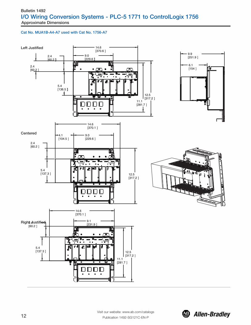
Approximate Dimensions
9.0[229.6 ]
11.1[281.7 ]
12.5[317.2 ]
5.4[137 ]
10.4[263.6 ]
6.1[154 ]
9.9[251.9 ]
11.1[281.7 ]
12.5[317.2 ]
2.4[60.1 ]
5.4[137 ]
2.4[60.2 ]
9.1[230.7 ]
10.4[264.1 ]
Cat No. MUA1B-A4-A7 used with Cat No. 1756-A4
Left Justified
Right Justified
Bulletin 1492
I/O Wiring Conversion Systems - PLC-5 1771 to ControlLogix 1756
12Visit our website: www.ab.com/catalogs
Publication 1492-SG121C-EN-P
Approximate Dimensions
9.9[251.9 ]
6.1[154 ]
9.0[229.6 ]]
2.4[60.2 ]]
12.5[317.2 ]
5.4[136.5 ]]
14.6[370.6 ]
11.1[281.7 ]
9.0[229.6 ]
4.1[104.5 ]
2.4[60.2 ]
12.5[317.2 ]
14.6[370.1 ]
5.4[137.3 ]
14.6[370.1 ]
9.1[231.9 ]
2.4[60.2 ]
12.5[317.2 ]
11.1[281.7 ]
5.4[137.3 ]
2.4[60.2 ]
Cat No. MUA1B-A4-A7 used with Cat No. 1756-A7
Left Justified
Centered
Right Justified
Bulletin 1492
I/O Wiring Conversion Systems - PLC-5 1771 to ControlLogix 1756
13Visit our website: www.ab.com/catalogs
Publication 1492-SG121C-EN-P
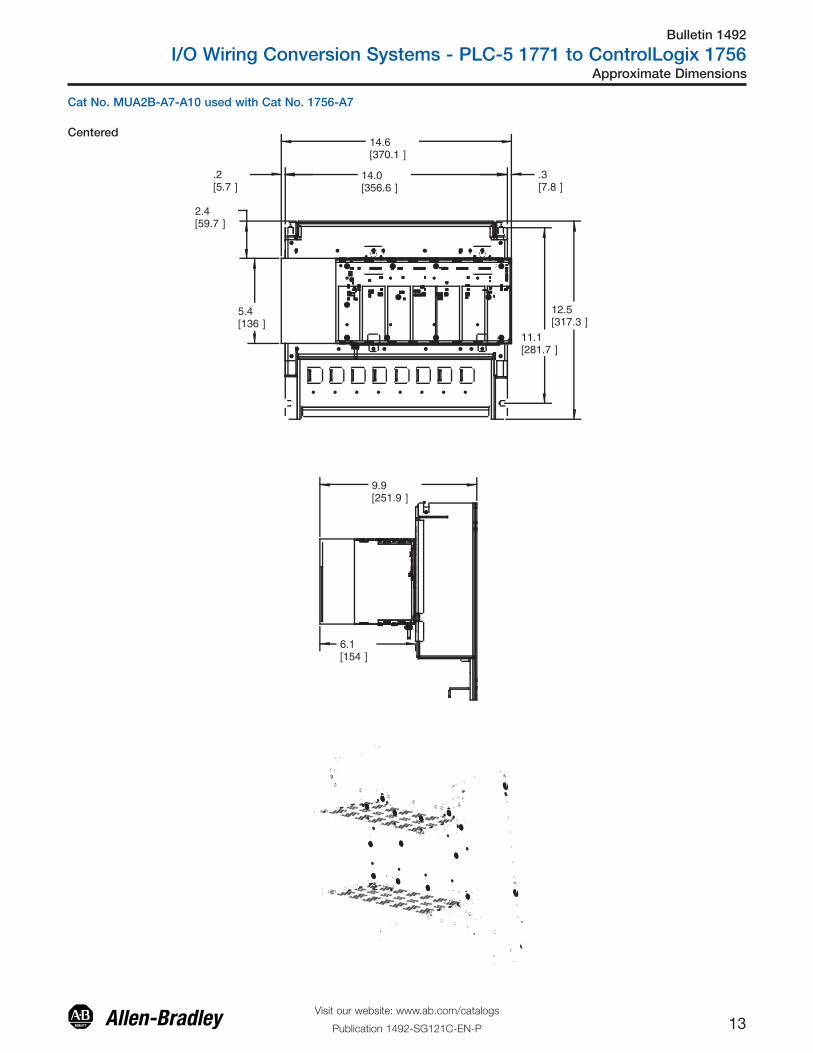
Approximate Dimensions
11.1[281.7 ]
12.5[317.3 ]
14.0[356.6 ]
.2[5.7 ]
2.4[59.7 ]
.3[7.8 ]
14.6[370.1 ]
5.4[136 ]
9.9[251.9 ]
6.1[154 ]
Cat No. MUA2B-A7-A10 used with Cat No. 1756-A7
Centered

Bulletin 1492
I/O Wiring Conversion Systems - PLC-5 1771 to ControlLogix 1756
14Visit our website: www.ab.com/catalogs
Publication 1492-SG121C-EN-P
Approximate Dimensions
2.4[60.2 ]
2.5[63.5 ]
14.0[356.6 ]
19.1[485 ]
11.1[281.7 ]
12.5[317.3 ]
5.4[137.3 ]
.2[5.5 ]
19.1[485 ]
14.0[356.6 ]
11.1[281.7 ]
12.5[317.3 ]
2.4[60.2 ]
5.4[137 ]
9.9[252.3 ]
6.1[154.4 ]
19.1[485 ]
14.0[356.6 ]
5.1[130 ]2.4
[60.2 ]
11.1[281.7 ]
12.5[317.3 ]
5.4[136 ]
SCALE 0.300
Cat No. MUA2B-A7-A10 used with Cat No. 1756-A10
Left Justified
Centered
Right Justified

Bulletin 1492
I/O Wiring Conversion Systems - PLC-5 1771 to ControlLogix 1756
15Visit our website: www.ab.com/catalogs
Publication 1492-SG121C-EN-P
Approximate Dimensions
19.0[483.6 ]
2.4[60.2 ]
12.5[317.3 ]
5.4[137 ]
11.1[281.7 ]
19.2[486.9 ]
6.1[154.4 ]
9.9[252.3 ]
Cat No. MUA3-A10-A13 used with Cat No. 1756-A10
Centered

Bulletin 1492
I/O Wiring Conversion Systems - PLC-5 1771 to ControlLogix 1756
16Visit our website: www.ab.com/catalogs
Publication 1492-SG121C-EN-P
Approximate Dimensions
23.2[588 ]
2.4[60.2 ]
5.4[137 ]
.7[18 ]
19.0[483.6 ]
12.5[317.3 ]
11.1[281.7 ]
2.2[56.8 ]
1.9[47.4 ]
2.4[59.9 ]
19.0[483.6 ]23.2[588 ]
11.2[285.6 ]
23.2[588 ]
4.1[103.1 ]
2.4[60.2 ]
5.4[137 ] 11.1
[281.7 ]
9.6[243.9 ]
5.7[146 ]
5.4[137 ]
Cat No. MUA3-A10-A13 used with Cat No. 1756-A13
Left Justified
Centered
Right Justified

Bulletin 1492
I/O Wiring Conversion Systems - PLC-5 1771 to ControlLogix 1756
17Visit our website: www.ab.com/catalogs
Publication 1492-SG121C-EN-P
Approximate Dimensions
2.4[60.2 ]
24.0[610.6 ]
23.2[588 ]
12.5[316.7 ]
11.1[281.7 ]
5.4[137 ]
9.6[243.7 ]
5.7[145.9 ]
Cat No. MUA4-A13-A17 used with Cat No. 1756-A13
Centered

Bulletin 1492
I/O Wiring Conversion Systems - PLC-5 1771 to ControlLogix 1756
18Visit our website: www.ab.com/catalogs
Publication 1492-SG121C-EN-P
Approximate Dimensions
Cat No. MUA4-A13-A17 used with Cat No. 1756-A17
29.1[737.9 ]
24.0[610.6 ]
.2[6.2 ]
2.4[60.1 ]
4.8[121 ]
12.5[316.7 ]
11.1[281.7 ]
3.6[91.7 ]2.4
[60.1 ]
5.4[137 ]
1.4[35.6 ]
12.5[316.7 ]
11.1[281.7 ]
24.0[610.6 ]
5.1[130 ]2.4
[60.1 ]
5.4[137 ]
11.1[281.7 ]
12.5[316.7 ]
24.0[610.6 ]
29.1[737.9 ]
29.1[737.9 ]
6.1[154 ]
9.9[251.9 ]
LeftJustified
Centered
RightJustified
Dimensions are shown in incles (millimeters). Dimensions are not intended for manufacturing purposes.

Bulletin 1492
I/O Wiring Conversion Systems - PLC-5 1771 to ControlLogix 1756
19Visit our website: www.ab.com/catalogs
Publication 1492-SG121C-EN-P
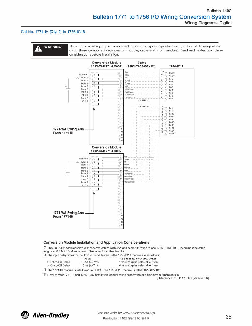
Wiring Diagrams - Digital
There are several key application considerations and system specifications (bottom of drawing) when using these components (conversion module, cable and input module). Read and understand these considerations before installation.
WARNING
� This Bul. 1492 cable consists of 2 separate cables (cable “A” and cable “B”) wired to one 1756-IA16 RTB. Recommended cablelengths of 0.5 M / 0.5 M are shown. See table 2 for other lengths.
� The 1771-IA, -IA2 module is rated 87V to 138V AC and 97V to 138V DC. The 1756-IA16 module is rated 79V to 132V AC only.
� Refer to your 1771-IA, -IA2 and 1756-IA16 Installation Manual wiring schematics and diagrams for more details. [Reference Doc: 41170-952 (Version 02)]
� The input delay times for the 1771-IA, -IA2 module versus the 1756-IA16 module are as follows: 1771-IA, -IA2 1756-IA16 w/ 1492-C005005XEa) Off-to-On Delay 24ms (+/-10ms) 10ms max (plus selectable filter)b) On-to-Off Delay 24ms (+/-10ms) 8ms max (plus selectable filter)
Conversion Module Installation and Application Considerations
B
34567
A
1771-WA Swing ArmFrom 1771-IA , -IA2
1771-WA Swing ArmFrom 1771-IA , -IA2
012
Black
WhiteRed
Green
Orange
Blue
White/Black
Red/BlackGreen/Black
Orange/Black
1
19
345678910111213
15161718
20
14
2
24
212223
25
L1
L2
10L2-0
IN-01
IN-12
IN-23
IN-34
IN-45
IN-56
IN-67
IN-78
IN-811
IN-912
IN-1013
IN-1114
IN-1215
IN-1316
IN-1417
IN-1518
L2-120
9L2-0
19L2-1
CABLE “A”
CABLE “B”
Not used
Input 0Input 1
Input 2Input 3Input 4Input 5
Input 6
Input 7L2
B
34567
A012
1
19
345678910111213
15161718
20
14
2
24
212223
25
L1
L2
Not used
Input 8Input 9
Input 10Input 11Input 12Input 13
Input 14
Input 15L2
Black
WhiteRed
Green
Orange
Blue
White/Black
Red/BlackGreen/Black
Orange/Black
Conversion Module1492-CM1771-LD007
Conversion Module1492-CM1771-LD007
Cable1492-C005005XE� 1756-IA16
Cat No. 1771-IA (Qty. 2) to 1756-IA16

Bulletin 1492
I/O Wiring Conversion Systems - PLC-5 1771 to ControlLogix 1756
20Visit our website: www.ab.com/catalogs
Publication 1492-SG121C-EN-P
Wiring Diagrams - Digital
There are several key application considerations and system specifications (bottom of drawing) when using these components (conversion module, cable and input module). Read and understand these considerations before installation.
WARNING
� This Bul. 1492 cable consists of 2 separate cables (cable “A” and cable “B”) wired to one 1756-IA16 RTB. Recommended cablelengths of 0.5 M / 0.5 M are shown. See table 2 for other lengths.
� The 1771-IA, -IA2 module is rated 87V to 138V AC and 97V to 138V DC. The 1756-IA16 module is rated 79V to 132V AC only.
� Refer to your 1771-IA, -IA2 and 1756-IA16 Installation Manual wiring schematics and diagrams for more details. [Reference Doc: 41170-952 (Version 02)]
� The input delay times for the 1771-IA, -IA2 module versus the 1756-IA16 module are as follows: 1771-IA, -IA2 1756-IA16 w/ 1492-C005005XEa) Off-to-On Delay 24ms (+/-10ms) 10ms max (plus selectable filter)b) On-to-Off Delay 24ms (+/-10ms) 8ms max (plus selectable filter)
Conversion Module Installation and Application Considerations
B
34567
A
1771-WA Swing ArmFrom 1771-IA , -IA2
1771-WA Swing ArmFrom 1771-IA , -IA2
012
Black
WhiteRed
Green
Orange
Blue
White/Black
Red/BlackGreen/Black
Orange/Black
1
19
345678910111213
15161718
20
14
2
24
212223
25
L1
L2
10L2-0
IN-01
IN-12
IN-23
IN-34
IN-45
IN-56
IN-67
IN-78
IN-811
IN-912
IN-1013
IN-1114
IN-1215
IN-1316
IN-1417
IN-1518
L2-120
9L2-0
19L2-1
CABLE “A”
CABLE “B”
Not used
Input 0Input 1
Input 2Input 3Input 4Input 5
Input 6
Input 7L2
B
34567
A012
1
19
345678910111213
15161718
20
14
2
24
212223
25
L1
L2
Not used
Input 8Input 9
Input 10Input 11Input 12Input 13
Input 14
Input 15L2
Black
WhiteRed
Green
Orange
Blue
White/Black
Red/BlackGreen/Black
Orange/Black
Conversion Module1492-CM1771-LD007
Conversion Module1492-CM1771-LD007
Cable1492-C005005XE� 1756-IA16
Cat No. 1771-IA2 (Qty. 2) to 1756-IA16

Bulletin 1492
I/O Wiring Conversion Systems - PLC-5 1771 to ControlLogix 1756
21Visit our website: www.ab.com/catalogs
Publication 1492-SG121C-EN-P
Wiring Diagrams - Digital
Conversion Module Installation and Application Considerations� This Bul. 1492 cable consists of a cable wired to one 1756-IA16 RTB. Recommended cable lengths of 0.5M or 1.0M (005=0.5M, 010=1.0M). See table 2 for other lengths.
� The input delay times for the 1771-IAD module versus the 1756-IA16 module are as follows: 1771-IAD 1756-IA16 w/ 1492-CONCAB005Xa) Off-to-On Delay 5ms (+/-3ms) @120VAC 10ms max (plus selectable filter)b) On-to-Off Delay 25ms (+/-5ms) 8ms max (plus selectable filter)
� The 1771-IAD module is rated 79V to 138V AC or DC. The 1756-IA16 module is rated 74V to 132V AC. If the inputsource voltage is DC use a 1756-IH16l and 1492-CM1771-LD002 conversion module.
� Refer to your 1771-IAD and 1756-IA16 Installation Manual wiring schematics and diagrams for more details. [Reference Doc: 41170-925 (Version 02)]
10L2-0
IN-01
IN-12
IN-23
IN-34
IN-45
IN-56
IN-67
IN-78
IN-811
IN-912
IN-1013
IN-1114
IN-1215
IN-1316
IN-1417
IN-1518
Black
WhiteRed
Green
Orange
Blue
White/Black
Red/BlackGreen/Black
Orange/BlackBlue/Black
Black/White
Red/White
Green/White
Blue/White
Black/Red
White/Red
Orange/Red
Blue/Red
Red/GreenL2-1
20
9L2-0
19L2-1
A
1
00
19
013
024
035
046
057
068
079
E
10111012111312
13151416151716
17 18
20
14
2
Input 14
Input 16Input 15
Input 17
Input 04
Input 06Input 05
Input 07
Input 00
Input 02Input 01
Input 03
Input 10
Input 12Input 11
Input 13
Terminal A
Terminal E
BCD
Terminal BTerminal CTerminal D
L1
L2
24
212223
25
1756-IA16
1771-WH Swing ArmFrom 1771-IAD
There are several key application considerations and system specifications (bottom of drawing) when using these components (conversion module, cable and input module). Read and understand these considerations before installation.
WARNING
Conversion Module1492-CM1771-LD001
Cable1492-CONCAB005X�
Cat No. 1771-IAD to 1756-IA16

Bulletin 1492
I/O Wiring Conversion Systems - PLC-5 1771 to ControlLogix 1756
22Visit our website: www.ab.com/catalogs
Publication 1492-SG121C-EN-P
Wiring Diagrams - Digital
1756-IH16I
1771-WH Swing ArmFrom 1771-IAD
There are several key application considerations and system specifications (bottom of drawing) when using these components (conversion module, cable and input module). Read and understand these considerations before installation.
WARNING
Conversion Module Installation and Application Considerations� The input delay times for the 1771-IAD module versus 1756-IH16I module are as follows: 1771-IAD 1756-IH16Ia) Off-to-On Delay 3ms @120V DC 2ms (plus selectable filter)b) On-to-Off Delay 25ms (+/-5ms) 6ms (plus selectable filter)� The 1771-IAD module is rated 79V to 138V AC or DC. The 1756-IH16I module is rated 90V to 146V DC. If the inputspurce voltage is AC use a 1756-IA16 and 1492-CM1771-LD002 conversion module.� Refer to your 1771-IAD and 1756-IH16I Installation Manual wiring schematics and diagrams for more details.
[Reference Doc: 41170-927 (Version 02)]
A
00
01
02
03
04
05
06
07
E
10
11
12
13
14
15
16
17
Input 14
Input 16
Input 15
Input 17
Input 04
Input 06
Input 05
Input 07
Input 00
Input 02
Input 01
Input 03
Input 10
Input 12
Input 11
Input 13
Terminal A
Terminal E
BCD
Terminal BTerminal CTerminal D
+
-
12345678910111213
151617181920
14
21222324252627282930313233
353637
34
IN-0
21
IN-1
43
IN-2
65
IN-3
87
IN-4
109
IN-5
1211
IN-6
1413
Orange
Blue
White/Black
Red/BlackGreen/Black
Orange/BlackBlue/Black
Black/White
Red/White
Green/White
Blue/White
Black/Red
White/Red
Orange/Red
Blue/Red
Red/GreenIN-7
1615
IN-8
1817
IN-9
2019
IN-10
2221
IN-11
2423
IN-12
2625
IN-13
2827
IN-14
3029
Orange/Green
Black/White/Red
White/Black/Red
Red/Black/WhiteGreen/Black/White
Orange/Black/WhiteBlue/Black/White
Black/Red/Green
White/Red/Green
Red/Black/Green
Green/Black/Orange
Orange/Black/Green
Blue/White/Orange
Black/White/Orange
White/Red/Orange
Orange/White/BlueIN-15
3231
GND-0
GND-1
GND-2
GND-3
GND-4
GND-5
GND-6
GND-7
GND-8
GND-9
GND-10
GND-11
GND-12
GND-13
GND-14
GND-15
Conversion Module1492-CM1771-LD002
Cable1492-CONCAB005Y�
Cat No. 1771-IAD to 1756-IH16I

Bulletin 1492
I/O Wiring Conversion Systems - PLC-5 1771 to ControlLogix 1756
23Visit our website: www.ab.com/catalogs
Publication 1492-SG121C-EN-P
Wiring Diagrams - Digital
1771-WN Swing ArmFrom 1771-IAN
There are several key application considerations and system specifications (bottom of drawing) when using these components (conversion module, cable and input module). Read and understand these considerations before installation.
WARNING
Conversion Module Installation and Application Considerations� The input delay times for the 1771-IAN module versus 1756-IA32 module are as follows: 1771-IAN 1756-IA32
a) Off-to-On Delay 10ms (+/-7ms) 10ms max (plus selectable filter)b) On-to-Off Delay 20ms (+/-15ms) 8ms max (plus selectable filter)
� The 1771-IAN has 4 groups(allowing 4 seperate power supplies) and the 1756-IA32 has 2 groups. This module/cable combination ties Groups 0 & 1 from the 1771-IAN to Group 0 on the 1756-IA32 and it ties Groups 2 & 3 from the 1771-IAN to Group 1 on the 1756-IA32. Field wiring modification must be made to accommodate this if multiple supplies were used. If 4 supplies were used, 2 must be removed.
� Refer to your 1771-IAN and 1756-IA32 Installation Manual wiring schematics and diagrams for more details.
[Reference Doc: 41170-930 (Version 02)]
1756-IA32
18L2-0
IN-01
IN-1619
IN-12
IN-1720
IN-23
IN-1821
IN-34
IN-1922
IN-45
IN-2023
IN-56
IN-2124
IN-67
IN-2225
Black
WhiteRed
Green
Orange
Blue
White/Black
Red/BlackGreen/Black
Orange/BlackBlue/Black
Black/White
Red/White
Green/White
Blue/White
Black/Red
White/Red
Orange/Red
Blue/RedRed/Green
IN-78
1234
3
5
226
4
7
238
5
9
2410
6
11
2512
7
13
26
8
15
2716
9
17
2818
10
1920
14
12
213122
13233224
14
253326
15273428
16293530
17313632
18
3337
30
353836
2
37
34
L2-136
IN-2326
IN-89
IN-2427
IN-910
IN-2528
IN-1011
IN-2629
IN-1112
IN-2730
IN-1213
IN-2831
IN-1314
IN-2932
IN-1415
IN-3033
Orange/Green
Black/White/Red
White/Black/Red
Red/Black/WhiteGreen/Black/White
Orange/Black/WhiteBlue/Black/White
Black/Red/Green
White/Red/Green
Red/Black/Green
Green/Black/Orange
Orange/Black/Green
Blue/White/Orange
Black/White/Orange
White/Red/Orange
Orange/White/Blue
IN-1516
IN-313417
L2-0White/Red/Blue
L2-13519
21
11
Common 0
1
39
2029
40
Common 2
L1
L2
Input 01Input 01Input 02Input 02Input 03Input 03Input 04Input 04
Input 05Input 05Input 06Input 06Input 07Input 07
Input 10
Input 11
Input 10
Input 12
Input 13Input 13Input 14Input 14Input 15Input 15Input 16Input 16Input 17Input 17
Input 00Input 00
Input 11
Input 12
Common 0Common 1Common 1Common 2
Common 3Common 3
Conversion Module1492-CM1771-LD003
Cable1492-CONCAB005Z�
Cat No. 1771-IAN to 1756-IA32

Bulletin 1492
I/O Wiring Conversion Systems - PLC-5 1771 to ControlLogix 1756
24Visit our website: www.ab.com/catalogs
Publication 1492-SG121C-EN-P
Wiring Diagrams - Digital
There are several key application considerations and system specifications (bottom of drawing) when using these components (conversion module, cable and input module). Read and understand these considerations before installation.
WARNING
B
34567
A012
Black
WhiteRed
Green
Orange
Blue
White/Black
Red/BlackGreen/Black
Orange/Black
1
19
345678910111213
15161718
20
14
2
24
212223
25
+
-
1756-IB16
10GND-0
IN-01
IN-12
IN-23
IN-34
IN-45
IN-56
IN-67
IN-78
IN-811
IN-912
IN-1013
IN-1114
IN-1215
IN-1316
IN-1417
IN-1518
GND-120
9GND-0
19GND-1
CABLE “A”
CABLE “B”
Not used
Input 0Input 1
Input 2Input 3Input 4Input 5
Input 6
Input 7GND-1
B
34567
A012
1
19
345678910111213
15161718
20
14
2
24
212223
25
Not used
Input 0Input 1
Input 2Input 3Input 4Input 5
Input 6
Input 7GND-1
� The 1771-IB module is rated 24V DC. The 1756-IB16 module is rated 10 - 31V DC only.
� Refer to your 1771-IB and 1756-IB16 Installation Manual wiring schematics and diagrams for more details. [Reference Doc: 41170-995 (Version 00)]
� The input delay times for the 1771-IB module versus the 1756-IB16 module are as follows: 1771-IB 1756-IB16 w/ 1492-C005005XEa) Off-to-On Delay 24ms (+/-10ms) 1ms max (plus selectable filter)b) On-to-Off Delay 24ms (+/-10ms) 2ms max (plus selectable filter)
Black
WhiteRed
Green
Orange
Blue
White/Black
Red/BlackGreen/Black
Orange/Black
+
-
Conversion Module Installation and Application Considerations� This Bul. 1492 cable consists of 2 separate cables (cable “A” and cable “B”) wired to one 1756-IB16 RTB. Recommended cablelengths of 0.5 M / 0.5 M are shown. See table 2 for other lengths.
1771-WA Swing ArmFrom 1771-IB
1771-WA Swing ArmFrom 1771-IB
Conversion Module1492-CM1771-LD007
Conversion Module1492-CM1771-LD007
Cable1492-C005005XE�
Cat No. 1771-IB (Qty. 2) to 1756-IB16

Bulletin 1492
I/O Wiring Conversion Systems - PLC-5 1771 to ControlLogix 1756
25Visit our website: www.ab.com/catalogs
Publication 1492-SG121C-EN-P
Wiring Diagrams - Digital
1756-IB16
10GND-0
IN-01
IN-12
IN-23
IN-34
IN-45
IN-56
IN-67
IN-78
IN-811
IN-912
IN-1013
IN-1114
IN-1215
IN-1316
IN-1417
IN-1518
Black
WhiteRed
Green
Orange
Blue
White/Black
Red/BlackGreen/Black
Orange/BlackBlue/Black
Black/White
Red/White
Green/White
Blue/White
Black/Red
White/Red
Orange/Red
Blue/Red
Red/GreenGND-1
20
9GND-0
19GND-1
A
1
00
19
013
024
035
046
057
068
079
E
10111012111312
13151416151716
17 18
20
14
2
Input 14
Input 16Input 15
Input 17
Input 04
Input 06Input 05
Input 07
Input 00
Input 02Input 01
Input 03
Input 10
Input 12Input 11
Input 13
Terminal A
Terminal E
BCD
Terminal BTerminal CTerminal D
+
-
24
212223
25
Conversion Module Installation and Application Considerations� This Bul. 1492 cable consists of a cable wired to one 1756-IB16 RTB. Recommended cable lengths of 0.5M or 1.0M (005=0.5M, 010=1.0M). See table 2 for other lengths.
� The input delay times for the 1771-IBD module versus the 1756-IB16 module are as follows: 1771-IBD 1756-IB16 w/ 1492-CONCAB005Xa) Off-to-On Delay 1ms 1ms (plus selectable filter)b) On-to-Off Delay 1ms 2ms (plus selectable filter)
� Refer to your 1771-IBD and 1756-IB16 Installation Manual wiring Schematics and diagrams for more details. [Reference Doc: 41170-926 (Version 02)]
1771-WH Swing ArmFrom 1771-IBD
There are several key application considerations and system specifications (bottom of drawing) when using these components (conversion module, cable and input module). Read and understand these considerations before installation.
WARNING
Conversion Module1492-CM1771-LD001
Cable1492-CONCAB005X�
Cat No. 1771-IBD to 1756-IB16

Bulletin 1492
I/O Wiring Conversion Systems - PLC-5 1771 to ControlLogix 1756
26Visit our website: www.ab.com/catalogs
Publication 1492-SG121C-EN-P
Wiring Diagrams - Digital
1771-WN Swing ArmFrom 1771-IBN
There are several key application considerations and system specifications (bottom of drawing) when using these components (conversion module, cable and input module). Read and understand these considerations before installation.
WARNING
1756-IB32
18GND-0
IN-01
IN-1619
IN-12
IN-1720
IN-23
IN-1821
IN-34
IN-1922
IN-45
IN-2023
IN-56
IN-2124
IN-67
IN-2225
Black
WhiteRed
Green
Orange
Blue
White/Black
Red/BlackGreen/Black
Orange/BlackBlue/Black
Black/White
Red/White
Green/White
Blue/White
Black/Red
White/Red
Orange/Red
Blue/RedRed/Green
IN-78
1234
3
5
226
4
7
238
5
9
2410
6
11
2512
7
13
26
8
15
2716
9
17
2818
10
1920
14
12
213122
13233224
14
253326
15273428
16293530
17313632
18
3337
30
353836
2
37
34
GND-136
IN-2326
IN-89
IN-2427
IN-910
IN-2528
IN-1011
IN-2629
IN-1112
IN-2730
IN-1213
IN-2831
IN-1314
IN-2932
IN-1415
IN-3033
Orange/Green
Black/White/Red
White/Black/Red
Red/Black/WhiteGreen/Black/White
Orange/Black/WhiteBlue/Black/White
Black/Red/Green
White/Red/Green
Red/Black/Green
Green/Black/Orange
Orange/Black/Green
Blue/White/Orange
Black/White/Orange
White/Red/Orange
Orange/White/Blue
IN-1516
IN-313417
GND-0White/Red/Blue
GND-135
Input 01Input 01Input 02Input 02Input 03Input 03Input 04Input 04
Input 05Input 05Input 06Input 06Input 07Input 07
Input 10
Input 11
Input 10
Input 12
Input 13Input 13Input 14Input 14Input 15Input 15Input 16Input 16Input 17Input 17
Input 00
19
21
11
dc Common 0
1Input 00
Input 11
Input 12
39
2029
40
+
-
dc Common 2
dc Common 0dc Common 1dc Common 1
dc Common 3dc Common 2
dc Common 3
Conversion Module Installation and Application Considerations� The input delay times for the 1771-IBN module versus 1756-IB32 module are as follows: 1771-IBN 1756-IB32
a) Off-to-On Delay 6ms (+/-2ms) 1ms (plus selectable filter)b) On-to-Off Delay 6ms (+/-2ms) 1ms (plus selectable filter)
� The 1771-IBN has 4 groups(allowing 4 seperate power supplies) and the 1756-IB32 has 2 groups. This module/cable combination ties Groups 0 & 1 from the 1771-IBN to Group 0 on the 1756-IB32 and it ties Groups 2 & 3 from the 1771-IBN to Group 1 on the 1756-IB32. Field wiring modification must be made to accommodate this if multiple supplies were used. If 4 supplies were used, 2 must be removed.
� Refer to your 1771-IBN and 1756-IB32 Installation Manual wiring schematics and diagrams for more details.
[Reference Doc: 41170-929 (Version 02)]
Conversion Module1492-CM1771-LD003
Cable1492-CONCAB005Z�
Cat No. 1771-IBN to 1756-IB32

Bulletin 1492
I/O Wiring Conversion Systems - PLC-5 1771 to ControlLogix 1756
27Visit our website: www.ab.com/catalogs
Publication 1492-SG121C-EN-P
Wiring Diagrams - Digital
There are several key application considerations and system specifications (bottom of drawing) when using these components (conversion module, cable and input module). Read and understand these considerations before installation.
WARNING
B
34567
A012
Black
WhiteRed
Green
Orange
Blue
White/Black
Red/BlackGreen/Black
Orange/Black
1
19
345678910111213
15161718
20
14
2
24
212223
25
+
-
10GND-0
IN-01
IN-12
IN-23
IN-34
IN-45
IN-56
IN-67
IN-78
IN-811
IN-912
IN-1013
IN-1114
IN-1215
IN-1316
IN-1417
IN-1518
GND-120
9GND-0
19GND-1
CABLE “A”
CABLE “B”
Not used
Input 0Input 1
Input 2Input 3Input 4Input 5
Input 6
Input 7GND-1
B
34567
A012
1
19
345678910111213
15161718
20
14
2
24
212223
25
Not used
Input 0Input 1
Input 2Input 3Input 4Input 5
Input 6
Input 7GND-1
Black
WhiteRed
Green
Orange
Blue
White/Black
Red/BlackGreen/Black
Orange/Black
+
-
� The 1771-IC module is rated 42 to 56V DC. The 1756-IC16 module is rated 42 to 56V DC only.
� Refer to your 1771-IC and 1756-IC16 Installation Manual wiring schematics and diagrams for more details. [Reference Doc: 41170-996 (Version 00)]
� The input delay times for the 1771-IC module versus the 1756-IC16 module are as follows: 1771-IC 1756-IC16 w/ 1492-C005005XEa) Off-to-On Delay 12ms (+/-7ms) 1ms max (plus selectable filter)b) On-to-Off Delay 20ms (+/-7ms) 4ms max (plus selectable filter)
Conversion Module Installation and Application Considerations� This Bul. 1492 cable consists of 2 separate cables (cable “A” and cable “B”) wired to one 1756-IC16 RTB. Recommended cablelengths of 0.5 M / 0.5 M are shown. See table 2 for other lengths.
1771-WA Swing ArmFrom 1771-IC
1771-WA Swing ArmFrom 1771-IC
1756-IC16 Conversion Module1492-CM1771-LD007
Conversion Module1492-CM1771-LD007
Cable1492-C005005XE�
Cat No. 1771-IC (Qty. 2) to 1756-IC16

Bulletin 1492
I/O Wiring Conversion Systems - PLC-5 1771 to ControlLogix 1756
28Visit our website: www.ab.com/catalogs
Publication 1492-SG121C-EN-P
Wiring Diagrams - Digital
There are several key application considerations and system specifications (bottom of drawing) when using these components (conversion module, cable and input module). Read and understand these considerations before installation.
WARNING
10RTN
IN-01
IN-12
IN-23
IN-34
IN-45
IN-56
IN-67
IN-78
IN-811
IN-912
IN-1013
IN-1114
IN-1215
IN-1316
IN-1417
IN-1518
Black
WhiteRed
Green
Orange
Blue
White/Black
Red/BlackGreen/Black
Orange/BlackBlue/Black
Black/White
Red/White
Green/White
Blue/White
Black/Red
White/Red
Orange/Red
Blue/Red
Red/GreenRTN
20
9RTN
19RTN
A
1
00
19
013
024
035
046
057
068
079
E
10111012111312
13151416151716
17 18
20
14
2
Input 14
Input 16Input 15
Input 17
Input 04
Input 06Input 05
Input 07
Input 00
Input 02Input 01
Input 03
Input 10
Input 12Input 11
Input 13
Terminal A
Terminal E
BCD
Terminal BTerminal CTerminal D
� The 1771-ICD module is rated 20V to 60V AC or DC. The 1756-IC16 module is rated 30V to 60V DC.
� This Bul. 1492 cable consists of a cable wired to one 1756-IC16 RTB. Recommended cable lengths of0.5M or 1.0M (005=0.5M, 010=1.0M). See table 2 for other lengths.
� Refer to your 1771-ICD and 1756-IC16 Installation Manual wiring schematics and diagrams for more details.
[Reference Doc: 41171-001 (Version 00)]
1771-WH Swing ArmFrom 1771-ICD
� The input delay times for the 1771-ICD module versus the 1756-IC16 module are as follows: 1771-ICD 1756-IC16 w/ 1492-CONCAB005Xa) Off-to-On Delay 6ms (+/-2ms) 1ms max (plus selectable filter)b) On-to-Off Delay 20ms (+/-1ms) 4ms max (plus selectable filter)
+
24
212223
25
Conversion Module Installation and Application Considerations
--
Conversion Module1492-CM1771-LD001
Cable1492-CONCAB005X� 1756-IC16
Cat No. 1771-ICD to 1756-IC16

Bulletin 1492
I/O Wiring Conversion Systems - PLC-5 1771 to ControlLogix 1756
29Visit our website: www.ab.com/catalogs
Publication 1492-SG121C-EN-P
Wiring Diagrams - Digital
There are several key application considerations and system specifications (bottom of drawing) when using these components (conversion module, cable and input module). Read and understand these considerations before installation.
WARNING
Conversion Module Installation and Application Considerations � This Bul. 1492 cable consists of a cable wired to one 1756-IA16I RTB. Recommended cable lengths of 0.5M or 1.0M (005=0.5M, 010=1.0M). See table 2 for other lengths.
� The input delay times for the 1771-ID module versus the 1756-IA16I module are as follows: 1771-ID 1756-IA16I w/ 1492-C005005XL a) Off-to-On Delay 24ms (+/-10ms) 10ms max (plus selectable filter) b) On-to-Off Delay 24ms (+/-10ms) 8ms max (plus selectable filter)
� The 1771-ID module had a jumper selection of N.O. and N.C. outputs. The 1756-IA16I has both N.O. and N.C. outputs, but selection is by wiring termination on the 1756 swing arm. The 1492-CM1771-LD012 conversion module replaces the functionality of the 1771-ID jumpers with eight jumpers (JMP0 through JMP7). In the default position, the output will be N.O. If a N.C. output is required, change the jumper from pins 1-2 to pins 3-4.
� Refer to your 1771-ID and 1756-IA16I Installation Manual wiring schematics and diagrams for more details. Ensure 1756 output module ratings are not exceeded. [Reference Doc: 41170-993 (Version 00)]
12345
678910111213
151617181920
14
21222324252627282930313233
353637
34
LOAD
123456
Orange
Blue
White/Black
Red/BlackGreen/Black
Orange/BlackBlue/Black
Black/White
Red/White
Green/White
Blue/White
Black/Red
White/Red
Orange/Red
Blue/Red
Red/Green
7891011
Orange/Green
Black/White/Red
White/Black/Red
Red/Black/WhiteGreen/Black/White
Orange/Black/WhiteBlue/Black/White
Black/Red/Green
White/Red/Green
Red/Black/Green
Green/Black/Orange
Orange/Black/Green
Blue/White/Orange
Black/White/Orange
White/Red/Orange
Orange/White/Blue
12
L1L21
56789101112
234
1
3
2
4
N.O.
N.C.
1
3
2
4
N.O.
N.C.
JMP0
JMP1
1
3
2
4
N.O.
N.C.
JMP2
1
3
2
4
N.O.
N.C.
1
3
2
4
N.O.
N.C.
JMP3
JMP4
1
3
2
4
N.O.
N.C.
JMP5
1
3
2
4
N.O.
N.C.
JMP6
1
3
2
4
N.O.
N.C.
JMP7
12345
678910111213
151617181920
14
21222324252627282930313233
353637
34
Orange
Blue
White/Black
Red/BlackGreen/Black
Orange/BlackBlue/Black
Black/White
Red/White
Green/White
Blue/White
Black/Red
White/Red
Orange/Red
Blue/Red
Red/GreenOrange/Green
Black/White/Red
White/Black/Red
Red/Black/WhiteGreen/Black/White
Orange/Black/WhiteBlue/Black/White
Black/Red/Green
White/Red/Green
Red/Black/Green
Green/Black/Orange
Orange/Black/Green
Blue/White/Orange
Black/White/Orange
White/Red/Orange
Orange/White/Blue
1
56789101112
234
1
3
2
4
N.O.
N.C.
1
3
2
4
N.O.
N.C.
JMP0
JMP1
1
3
2
4
N.O.
N.C.
JMP2
1
3
2
4
N.O.
N.C.
1
3
2
4
N.O.
N.C.
JMP3
JMP4
1
3
2
4
N.O.
N.C.
JMP5
1
3
2
4
N.O.
N.C.
JMP6
1
3
2
4
N.O.
N.C.
JMP7
252627282930313233343536
NOT USED
NOT USEDNOT USED
131415161718192021222324
L1-6L2-6L1-7
L2-7L1-8L2-8
L2-9L1-9
L2-10L1-10
L1-11L2-11
NOT USEDNOT USEDNOT USEDNOT USEDNOT USEDNOT USEDNOT USEDNOT USED
L1-0
L2-0
L1-1L2-1L1-2L2-2
L2-3L1-3
L2-4L1-4
L1-5L2-5
LOADL1L2
L1-6
L2-6
L1-7L2-7L1-8L2-8
L2-9L1-9
L2-10L1-10
L1-11L2-11
L1-0L2-0L1-1L2-1L1-2L2-2
L2-3L1-3
L2-4L1-4
L1-5L2-5
CABLE”A”
CABLE”B”NOT USED
Conversion Module1492-CM1771-LD012
Conversion Module1492-CM1771-LD012
1771-WD Swing ArmFrom 1771-ID
1771-WD Swing ArmFrom 1771-ID
Cable1492-C005005XL� 1756-IA16I
Cat No. 1771-ID (Qty. 2) to 1756-IA16I

Bulletin 1492
I/O Wiring Conversion Systems - PLC-5 1771 to ControlLogix 1756
30Visit our website: www.ab.com/catalogs
Publication 1492-SG121C-EN-P
Wiring Diagrams - Digital
There are several key application considerations and system specifications (bottom of drawing) when using these components (conversion module, cable and input module). Read and understand these considerations before installation.
WARNING
Conversion Module1492-CM1771-LD012
Conversion Module1492-CM1771-LD012
1771-WD Swing ArmFrom 1771-ID01
1771-WD Swing ArmFrom 1771-ID01
Cable1492-C005005XL� 1756-IM16I
12345
678910111213
151617181920
14
21222324252627282930313233
353637
34
LOAD
123456
Orange
Blue
White/Black
Red/BlackGreen/Black
Orange/BlackBlue/Black
Black/White
Red/White
Green/White
Blue/White
Black/Red
White/Red
Orange/Red
Blue/Red
Red/Green
7891011
Orange/Green
Black/White/Red
White/Black/Red
Red/Black/WhiteGreen/Black/White
Orange/Black/WhiteBlue/Black/White
Black/Red/Green
White/Red/Green
Red/Black/Green
Green/Black/Orange
Orange/Black/Green
Blue/White/Orange
Black/White/Orange
White/Red/Orange
Orange/White/Blue
12
L1L21
56789101112
234
1
3
2
4
N.O.
N.C.
1
3
2
4
N.O.
N.C.
JMP0
JMP1
1
3
2
4
N.O.
N.C.
JMP2
1
3
2
4
N.O.
N.C.
1
3
2
4
N.O.
N.C.
JMP3
JMP4
1
3
2
4
N.O.
N.C.
JMP5
1
3
2
4
N.O.
N.C.
JMP6
1
3
2
4
N.O.
N.C.
JMP7
12345
678910111213
151617181920
14
21222324252627282930313233
353637
34
Orange
Blue
White/Black
Red/BlackGreen/Black
Orange/BlackBlue/Black
Black/White
Red/White
Green/White
Blue/White
Black/Red
White/Red
Orange/Red
Blue/Red
Red/GreenOrange/Green
Black/White/Red
White/Black/Red
Red/Black/WhiteGreen/Black/White
Orange/Black/WhiteBlue/Black/White
Black/Red/Green
White/Red/Green
Red/Black/Green
Green/Black/Orange
Orange/Black/Green
Blue/White/Orange
Black/White/Orange
White/Red/Orange
Orange/White/Blue
1
56789101112
234
1
3
2
4
N.O.
N.C.
1
3
2
4
N.O.
N.C.
JMP0
JMP1
1
3
2
4
N.O.
N.C.
JMP2
1
3
2
4
N.O.
N.C.
1
3
2
4
N.O.
N.C.
JMP3
JMP4
1
3
2
4
N.O.
N.C.
JMP5
1
3
2
4
N.O.
N.C.
JMP6
1
3
2
4
N.O.
N.C.
JMP7
252627282930313233343536
NOT USED
NOT USEDNOT USED
131415161718192021222324
L1-6L2-6L1-7
L2-7L1-8L2-8
L2-9L1-9
L2-10L1-10
L1-11L2-11
NOT USEDNOT USEDNOT USEDNOT USEDNOT USEDNOT USEDNOT USEDNOT USED
L1-0
L2-0
L1-1L2-1L1-2L2-2
L2-3L1-3
L2-4L1-4
L1-5L2-5
LOADL1L2
L1-6
L2-6
L1-7L2-7L1-8L2-8
L2-9L1-9
L2-10L1-10
L1-11L2-11
L1-0L2-0L1-1L2-1L1-2L2-2
L2-3L1-3
L2-4L1-4
L1-5L2-5
CABLE”A”
CABLE”B”NOT USED
Conversion Module Installation and Application Considerations� This Bul. 1492 cable consists of 2 separate cables (cable “A” and cable “B”) wired to one 1756-IM16I RTB. Each cable can be either0.5M or 1.0M (005=0.5M, 010=1.0M). Ensure that cable A and cable B are connected to the correct module in the conversion
� The input delay times for the 1771-IM module versus the 1756-IM16I module are as follows: 1771-ID01 1756-IM16I w/ 1492-C005005XLa) Off-to-On Delay 20ms (+/-10ms) 10ms max (plus selectable filter)b) On-to-Off Delay 20ms (+/-10ms) 8ms max (plus selectable filter)
� The 1771-ID01module had a jumper selection of N.O. and N.C. outputs. The 1756-IM16I has both N.O. and N.C. outputs, but selection is by wiring termination on the 1756 swing arm. The 1492-CM1771-LD012 conversion module replaces the functionalityof the 1771-ID01 jumpers with eight jumpers (JMP0 through JMP7). In the default position, the output will be N.O. If a N.C. output isrequired, change the jumper from pins 1-2 to pins 3-4.
� Refer to your 1771-ID01 and 1756-IM16I Installation Manual wiring schematics and diagrams for more details. Ensure1756 output module ratings are not exceeded. [Reference Doc: 41171-015 (Version 00)]
Cat No. 1771-ID01(Qty. 2) to 1756-IM16I

Bulletin 1492
I/O Wiring Conversion Systems - PLC-5 1771 to ControlLogix 1756
31Visit our website: www.ab.com/catalogs
Publication 1492-SG121C-EN-P
Wiring Diagrams - Digital
There are several key application considerations and system specifications (bottom of drawing) when using these components (conversion module, cable and input module). Read and understand these considerations before installation.
WARNING
Conversion Module Installation and Application Considerations� The input delay times for the 1771-ID16 module versus 1756-IA16I module are as follows: 1771-ID16 1756-IA16Ia) Off-to-On Delay 0.57ms 10ms max (plus selectable filter)b) On-to-Off Delay 9ms or 18ms (selectable) 8ms max (plus selectable filter)� The 1771-ID16 module is rated 74V to 138V AC and105V to 138V DC. The 1756-IA16I is rated 79V to 132V AC. If the input source voltage is DC use a 1756-IH16I with this conversion module.� Refer to your 1771-ID16 and 1756-IA16I Installation Manual wiring schematics and diagrams for more details.
[Reference Doc: 41170-931 (Version 02)]
1771-WN Swing ArmFrom 1771-ID16
1 2
436587
121114131615181722212423262528273231343336353837910192029303940
Input 14
Input 16
Input 15
Input 17
Input 4
Input 6
Input 5
Input 7
Input 0
Input 2
Input 1
Input 3
Input 10
Input 12
Input 11
Input 13
Not usedNot usedNot usedNot usedNot usedNot usedNot usedNot used
12345678910111213
151617181920
14
21222324252627282930313233
353637
34
IN-0
21
IN-1
43
IN-2
65
IN-3
87
IN-4
109
IN-5
1211
IN-6
1413
Orange
Blue
White/Black
Red/Black
Green/Black
Orange/Black
Blue/Black
Black/White
Red/White
Green/White
Blue/White
Black/Red
White/Red
Orange/Red
Blue/Red
Red/GreenIN-7
1615
IN-8
1817
IN-9
2019
IN-10
2221
IN-11
2423
IN-12
2625
IN-13
2827
IN-14
3029
Orange/Green
Black/White/Red
White/Black/Red
Red/Black/White
Green/Black/White
Orange/Black/White
Blue/Black/White
Black/Red/Green
White/Red/Green
Red/Black/Green
Green/Black/Orange
Orange/Black/Green
Blue/White/Orange
Black/White/Orange
White/Red/Orange
Orange/White/BlueIN-15
3231
L2-0
L2-1
L2-2
L2-3
L2-4
L2-5
L2-6
L2-7
L2-8
L2-9
L2-10
L2-11
L2-12
L2-13
L2-14
L2-15
L2
L1
L2-0
L2-1
L2-2
L2-3
L2-4
L2-5
L2-6
L2-7
L2-10
L2-11
L2-12
L2-13
L2-14
L2-15
L2-16
L2-17
1756-IA16I
Conversion Module1492-CM1771-LD004
Cable1492-CONCAB005Y�
Cat No. 1771-ID16 to 1756-IA16I

Bulletin 1492
I/O Wiring Conversion Systems - PLC-5 1771 to ControlLogix 1756
32Visit our website: www.ab.com/catalogs
Publication 1492-SG121C-EN-P
Wiring Diagrams - Digital
There are several key application considerations and system specifications (bottom of drawing) when using these components (conversion module, cable and input module). Read and understand these considerations before installation.
WARNING
Conversion Module Installation and Application Considerations� The input delay times for the 1771-ID16 module versus 1756-IH16I module are as follows: 1771-ID16 1756-IH16Ia) Off-to-On Delay 0.57ms 2ms max (plus selectable filter)b) On-to-Off Delay 9ms or 18ms (selectable) 6ms max (plus selectable filter)� The 1771-ID16 module is rated 74V to 138V AC and105V to 138V DC. The 1756-IH16I is rated 90V to 146V DC. If the input source voltage is AC use a 1756-IA16I with this conversion module.� Refer to your 1771-ID16 and 1756-IH16I Installation Manual wiring schematics and diagrams for more details.
[Reference Doc: 41170-932 (Version 02)]
1771-WN Swing ArmFrom 1771-ID16
IN-0
IN-1
IN-2
IN-3
IN-4
IN-5
IN-6
IN-7
IN-8
IN-9
IN-10
IN-11
IN-12
IN-13
IN-14
IN-15
GND-0
GND-1
GND-2
GND-3
GND-4
GND-5
GND-6
GND-7
GND-8
GND-9
GND-10
GND-11
GND-12
GND-13
GND-14
GND-15
1 2
436587
121114131615181722212423262528273231343336353837910192029303940
Input 14
Input 16
Input 15
Input 17
Input 4
Input 6
Input 5
Input 7
Input 0
Input 2
Input 1
Input 3
Input 10
Input 12
Input 11
Input 13
Not usedNot usedNot usedNot usedNot usedNot usedNot usedNot used
12345678910111213
151617181920
14
21222324252627282930313233
353637
34
2143658710912111413
Orange
Blue
White/Black
Red/Black
Green/Black
Orange/Black
Blue/Black
Black/White
Red/White
Green/White
Blue/White
Black/Red
White/Red
Orange/Red
Blue/Red
Red/Green
16151817201922212423262528273029
Orange/Green
Black/White/Red
White/Black/Red
Red/Black/White
Green/Black/White
Orange/Black/White
Blue/Black/White
Black/Red/Green
White/Red/Green
Red/Black/Green
Green/Black/Orange
Orange/Black/Green
Blue/White/Orange
Black/White/Orange
White/Red/Orange
Orange/White/Blue
3231
L2-0
L2-1
L2-2
L2-3
L2-4
L2-5
L2-6
L2-7
L2-10
L2-11
L2-12
L2-13
L2-14
L2-15
L2-16
L2-17
+
-
1756-IH16I
Conversion Module1492-CM1771-LD004
Cable1492-CONCAB005Y�
Cat No. 1771-ID16 to 1756-IH16I

Bulletin 1492
Bulletin 1771 to 1756 I/O Wiring Conversion System
33Visit our website: www.ab.com/catalogs
Publication 1492-SG121C-EN-P
Wiring Diagrams- Digital
There are several key application considerations and system specifications (bottom of drawing) when using these components (conversion module, cable and input module). Read and understand these considerations before installation.
WARNING
1771-WC Swing ArmFrom 1771-IG
1771-WC Swing ArmFrom 1771-IG
Conversion Module1492-CM1771-LA003
Conversion Module1492-CM1771-LA003
Cable1492-C005005XS� 1756-IG16
Conversion Module Installation and Application Considerations � This Bul. 1492 cable consists of 2 separate cables (cable “A” and cable “B”) wired to one 1756-IG16 RTB. Each cable can be either 0.5M or 1.0M (005=0.5M, 010=1.0M). Ensure that cable A and cable B are connected to the correct module in the conversion.
� The input delay times for the 1771-IG module versus the 1756-IG16 module are as follows: 1771-IG 1756-IG16 w/ 1492-C005005XS a) Off-to-On Delay 1ms (+/-10ms) 270ms max (plus selectable filter) b) On-to-Off Delay 1ms (+/-10ms) 390ms max (plus selectable filter)
� The 1771-IG module is rated 5V DC TTL INPUT MODULE. The 1756-IG16 module is rated 5V DC TTL INPUT MODULE only.
� Refer to your 1771-IG and 1756-IG16 Installation and User Manuals for additional information concerning comparisons of module wiring, features and configuration details. [Reference Doc: 41171-027 (Version 00)]
InputDevice
1325242322211918171612
SH
Input 0 + DC 10
IN-0IN-1
1
IN-2
234567
98
Red/White
Green/Black/White
Black/White/Red
White/Black/Red
Orange/Green
Red/Black/White
Orange/Red
Blue/Red
+ -
A
34567B
012
Common
Input 1 Input 2 Input 3 Input 4 Input 5 Input 6 Input 7
3456789101112141520
IN-3IN-4IN-5IN-6IN-7
+ DC -0
- DC -020
IN-8IN-9IN-10IN-11IN-12IN-13IN-14IN-15
+ DC -1
- DC -1
1325242322211918171612
SH
Red/White
Green/Black/White
Black/White/Red
White/Black/Red
Orange/Green
Red/Black/White
Orange/Red
Blue/Red
A
34567B
012
3456789101112141520
Input 0 + DC
Common
Input 1 Input 2 Input 3 Input 4 Input 5 Input 6 Input 7
111213141516171819
Black/Red
White/Red
Black/Red
White/Red
CABLE”B”
CABLE”A”+
- 5V DCSUPPLY
InputDevice
+ -
+
- 5V DCSUPPLY
Cat No. 1771-IG (Qty. 2) to 1756-IG16

Bulletin 1492
Bulletin 1771 to 1756 I/O Wiring Conversion System
34Visit our website: www.ab.com/catalogs
Publication 1492-SG121C-EN-P
Wiring Diagrams - Digital
There are several key application considerations and system specifications (bottom of drawing) when using these components (conversion module, cable and input module). Read and understand these considerations before installation.
WARNING
1771-WH, WHF, WHFB Swing ArmFrom 1771-IGD
Conversion Module1492-CM1771-LD006
Cable1492-CONCAB005X� 1756-IG16
� This Bul. 1492 cable consists of a cable wired to one 1756-IG16 RTB. Recommended cable lengths of 0.5M or 1.0M (005=0.5M, 010=1.0M). See table 2 for other lengths.
� The 1771-IGD module output current limits versus 1756-IG16 limits are as follows: 1771-IGD 1756-IG16 w/ 1492-CONCAB005Xa) Current/Point 122mA 110mAb) Current/Module 500mA 110mA
� The 1771-IGD is rated 5V DC. The 1756-IG16 is rated 4.5V to 5.5V DC.
� Refer to your 1771-IGD and 1756-IG16 Installation Manual wiring schematics and diagrams for more details. Ensure1756 output module ratings are not exceeded. [Reference Doc: 41171-004 (Version 00)]
Conversion Module Installation and Application Considerations
10DC-0+
IN-01
IN-12
IN-23
IN-34
IN-45
IN-56
IN-67
IN-78
IN-811
IN-912
IN-1013
IN-1114
IN-1215
IN-1316
IN-1417
IN-1518
Black
WhiteRed
Green
Orange
Blue
White/Black
Red/BlackGreen/Black
Orange/BlackBlue/Black
Black/White
Red/White
Green/White
Blue/White
Black/Red
White/Red
Orange/Red
Blue/Red
Red/GreenDC-1+
20
9RTN OUT-0
19RTN OUT-1
A
1
00
19
013
024
035
046
057
068
079
E
10111012111312
13151416151716
17 18
20
14
2
Input 00
+ dc
- dc
B
CD
DC InputDevice
+
-
+-
+ dc
+ dc
+ dc
24
212223
25
Input 01Input 02Input 03Input 04Input 05Input 06Input 07Input 08Input 09Input 10Input 11Input 12Input 13Input 14Input 15
Cat No. 1771-IGD to 1756-IG16
Bulletin 1492
Bulletin 1771 to 1756 I/O Wiring Conversion System
35Visit our website: www.ab.com/catalogs
Publication 1492-SG121C-EN-P
Wiring Diagrams- Digital
There are several key application considerations and system specifications (bottom of drawing) when using these components (conversion module, cable and input module). Read and understand these considerations before installation.
WARNING
� This Bul. 1492 cable consists of 2 separate cables (cable “A” and cable “B”) wired to one 1756-IC16 RTB. Recommended cablelengths of 0.5 M / 0.5 M are shown. See table 2 for other lengths.
� The 1771-IH module is rated 24V - 48V DC. The 1756-IC16 module is rated 30V - 60V DC.
� Refer to your 1771-IH and 1756-IC16 Installation Manual wiring schematics and diagrams for more details. [Reference Doc: 41170-997 (Version 00)]
� The input delay times for the 1771-IH module versus the 1756-IC16 module are as follows: 1771-IH 1756-IC16 w/ 1492-C005005XEa) Off-to-On Delay 15ms (+/-7ms) 1ms max (plus selectable filter)b) On-to-Off Delay 15ms (+/-7ms) 4ms max (plus selectable filter)
Conversion Module Installation and Application Considerations
B
34567
A012
Black
WhiteRed
Green
Orange
Blue
White/Black
Red/BlackGreen/Black
Orange/Black
1
19
345678910111213
15161718
20
14
2
24
212223
25
+
-
10GND-0
IN-01
IN-12
IN-23
IN-34
IN-45
IN-56
IN-67
IN-78
IN-811
IN-912
IN-1013
IN-1114
IN-1215
IN-1316
IN-1417
IN-1518
GND-120
9GND-0
19GND-1
CABLE “A”
CABLE “B”
Not used
Input 0Input 1
Input 2Input 3Input 4Input 5
Input 6
Input 7GND-0
B
34567
A012
1
19
345678910111213
15161718
20
14
2
24
212223
25
Not used
Input 0Input 1
Input 2Input 3Input 4Input 5
Input 6
Input 7GND-1
Black
WhiteRed
Green
Orange
Blue
White/Black
Red/BlackGreen/Black
Orange/Black
+
-
1771-WA Swing ArmFrom 1771-IH
1771-WA Swing ArmFrom 1771-IH
1756-IC16 Conversion Module1492-CM1771-LD007
Conversion Module1492-CM1771-LD007
Cable1492-C005005XE�
Cat No. 1771-IH (Qty. 2) to 1756-IC16
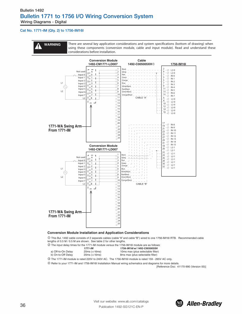
Bulletin 1492
Bulletin 1771 to 1756 I/O Wiring Conversion System
36Visit our website: www.ab.com/catalogs
Publication 1492-SG121C-EN-P
Wiring Diagrams - Digital
There are several key application considerations and system specifications (bottom of drawing) when using these components (conversion module, cable and input module). Read and understand these considerations before installation.
WARNING
� This Bul. 1492 cable consists of 2 separate cables (cable “A” and cable “B”) wired to one 1756-IM16I RTB. Recommended cablelengths of 0.5 M / 0.5 M are shown. See table 2 for other lengths.
� The 1771-IM module is rated 220V to 240V AC. The 1756-IM16I module is rated 159 - 265V AC only.
� Refer to your 1771-IM and 1756-IM16I Installation Manual wiring schematics and diagrams for more details. [Reference Doc: 41170-990 (Version 00)]
� The input delay times for the 1771-IM module versus the 1756-IM16I module are as follows: 1771-IM 1756-IM16I w/ 1492-C005005XHa) Off-to-On Delay 20ms (+/-6ms) 10ms max (plus selectable filter)b) On-to-Off Delay 20ms (+/-6ms) 8ms max (plus selectable filter)
Conversion Module Installation and Application Considerations
1756-IM16I Conversion Module1492-CM1771-LD007
Conversion Module1492-CM1771-LD007
Cable1492-C005005XH�
B
34567
A
1771-WA Swing ArmFrom 1771-IM
012
Black
WhiteRed
Green
Orange
Blue
White/Black
Red/BlackGreen/Black
Orange/Black
1
19
345678910111213
15161718
20
14
2
24
212223
25
L1
L2
2L2-0
IN-01
IN-13
IN-25
IN-37
IN-49
IN-511
IN-613
IN-715
IN-817
IN-919
IN-1021
IN-1123
IN-1225
IN-1327
IN-1429
IN-1531
L2-118
4L2-0
20L2-1
CABLE “A”
CABLE “B”
Not used
Input 0Input 1
Input 2Input 3Input 4Input 5
Input 6
Input 7L2
B
34567
A
1771-WA Swing ArmFrom 1771-IM
012
1
19
345678910111213
15161718
20
14
2
24
212223
25
L1
L2
Not used
Input 0Input 1
Input 2Input 3Input 4Input 5
Input 6
Input 7L2
Black
WhiteRed
GreenOrange
BlueWhite/Black
Red/BlackGreen/Black
Orange/Black
L2-0L2-0
6810121416
L2-1
L2-1L2-1L2-1L2-1
L2-1
22
26283032
24
L2-0L2-0L2-0L2-0
Cat No. 1771-IM (Qty. 2) to 1756-IM16I

Bulletin 1492
Bulletin 1771 to 1756 I/O Wiring Conversion System
37Visit our website: www.ab.com/catalogs
Publication 1492-SG121C-EN-P
Wiring Diagrams- Digital
1756-IM16I
1771-WH Swing ArmFrom 1771-IMD
There are several key application considerations and system specifications (bottom of drawing) when using these components (conversion module, cable and input module). Read and understand these considerations before installation.
WARNING
Conversion Module1492-CM1771-LD002
Cable1492-CONCAB005Y�
Conversion Module Installation and Application Considerations� The input delay times for the 1771-IMD module versus 1756-IM16I module are as follows: 1771-IMD 1756-IM16Ia) Off-to-On Delay 15ms (+/-8ms) 10ms (plus selectable filter)b) On-to-Off Delay 172ms (+/-56ms) 8ms (plus selectable filter)� The 1771-IMD module is rated 184V AC to 250V AC and 166V-230V DC. The 1756-IM16I module is rated 159V to 265V AC. A1756 input module with an equivalent DC voltage range to convert the 1771-IMD is not available.� Refer to your 1771-IMD and 1756-IM16I Installation Manual wiring schematics and diagrams for more details.
[Reference Doc: 41170-928 (Version 02)]
A
00
01
02
03
04
05
06
07
E
10
11
12
13
14
15
16
17
Input 14
Input 16
Input 15
Input 17
Input 04
Input 06
Input 05
Input 07
Input 00
Input 02
Input 01
Input 03
Input 10
Input 12
Input 11
Input 13
Terminal A
Terminal E
BCD
Terminal BTerminal CTerminal D
12345678910111213
151617181920
14
21222324252627282930313233
353637
34
IN-0
21
IN-1
43
IN-2
65
IN-3
87
IN-4
109
IN-5
1211
IN-6
1413
Orange
Blue
White/Black
Red/BlackGreen/Black
Orange/BlackBlue/Black
Black/White
Red/White
Green/White
Blue/White
Black/Red
White/Red
Orange/Red
Blue/Red
Red/GreenIN-7
1615
IN-8
1817
IN-9
2019
IN-10
2221
IN-11
2423
IN-12
2625
IN-13
2827
IN-14
3029
Orange/Green
Black/White/Red
White/Black/Red
Red/Black/WhiteGreen/Black/White
Orange/Black/WhiteBlue/Black/White
Black/Red/Green
White/Red/Green
Red/Black/Green
Green/Black/Orange
Orange/Black/Green
Blue/White/Orange
Black/White/Orange
White/Red/Orange
Orange/White/BlueIN-15
3231
L2-0
L2-1
L2-2
L2-3
L2-4
L2-5
L2-6
L2-7
L2-8
L2-9
L2-10
L2-11
L2-12
L2-13
L2-14
L2-15
L1
L2
Cat No. 1771-IMD to 1756-IM16I
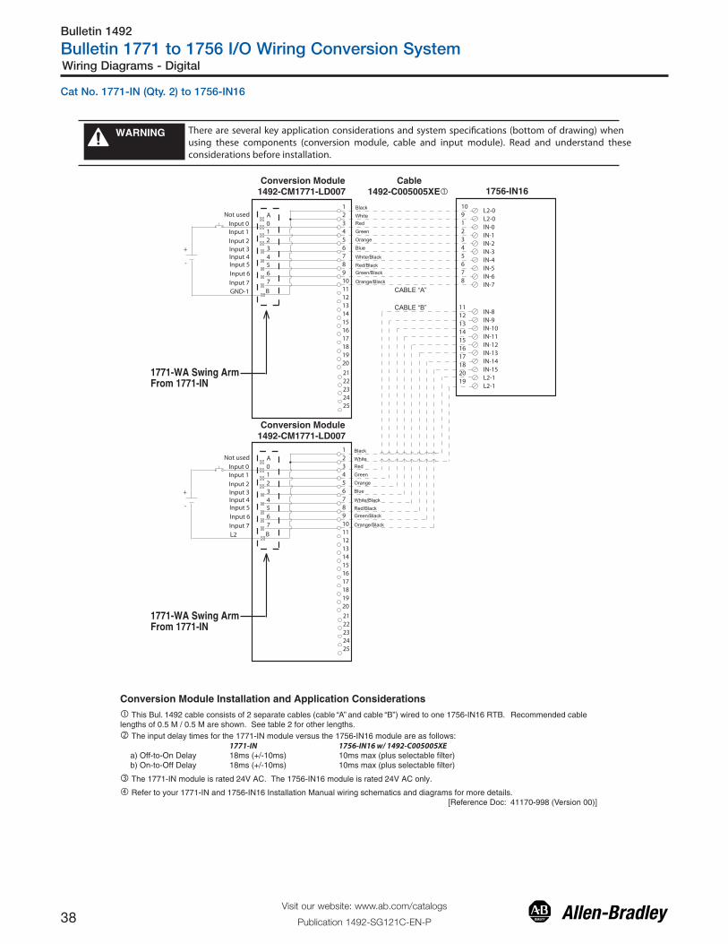
Bulletin 1492
Bulletin 1771 to 1756 I/O Wiring Conversion System
38Visit our website: www.ab.com/catalogs
Publication 1492-SG121C-EN-P
Wiring Diagrams - Digital
There are several key application considerations and system specifications (bottom of drawing) when using these components (conversion module, cable and input module). Read and understand these considerations before installation.
WARNING
� This Bul. 1492 cable consists of 2 separate cables (cable “A” and cable “B”) wired to one 1756-IN16 RTB. Recommended cablelengths of 0.5 M / 0.5 M are shown. See table 2 for other lengths.
� The 1771-IN module is rated 24V AC. The 1756-IN16 module is rated 24V AC only.
� Refer to your 1771-IN and 1756-IN16 Installation Manual wiring schematics and diagrams for more details. [Reference Doc: 41170-998 (Version 00)]
� The input delay times for the 1771-IN module versus the 1756-IN16 module are as follows: 1771-IN 1756-IN16 w/ 1492-C005005XEa) Off-to-On Delay 18ms (+/-10ms) 10ms max (plus selectable filter)b) On-to-Off Delay 18ms (+/-10ms) 10ms max (plus selectable filter)
Conversion Module Installation and Application Considerations
B
34567
A012
Black
WhiteRed
Green
Orange
Blue
White/Black
Red/BlackGreen/Black
Orange/Black
1
19
345678910111213
15161718
20
14
2
24
212223
25
+
-
1756-IN16
10L2-0
IN-01
IN-12
IN-23
IN-34
IN-45
IN-56
IN-67
IN-78
IN-811
IN-912
IN-1013
IN-1114
IN-1215
IN-1316
IN-1417
IN-1518
L2-120
9L2-0
19L2-1
CABLE “A”
CABLE “B”
Not used
Input 0Input 1
Input 2Input 3Input 4Input 5
Input 6
Input 7GND-1
B
34567
A012
1
19
345678910111213
15161718
20
14
2
24
212223
25
Not used
Input 0Input 1
Input 2Input 3Input 4Input 5
Input 6
Input 7L2
Black
WhiteRed
Green
Orange
Blue
White/Black
Red/BlackGreen/Black
Orange/Black
+
-
1771-WA Swing ArmFrom 1771-IN
1771-WA Swing ArmFrom 1771-IN
Conversion Module1492-CM1771-LD007
Conversion Module1492-CM1771-LD007
Cable1492-C005005XE�
Cat No. 1771-IN (Qty. 2) to 1756-IN16

Bulletin 1492
Bulletin 1771 to 1756 I/O Wiring Conversion System
39Visit our website: www.ab.com/catalogs
Publication 1492-SG121C-EN-P
Wiring Diagrams- Digital
There are several key application considerations and system specifications (bottom of drawing) when using these components (conversion module, cable and input module). Read and understand these considerations before installation.
WARNING
� This Bul. 1492 cable consists of a cable wired to one 1756-IN16 RTB. Recommended cable lengths of0.5M or 1.0M (005=0.5M, 010=1.0M). See table 2 for other lengths.
Conversion Module Installation and Application Considerations
1756-IN16
10L2-0
IN-01
IN-12
IN-23
IN-34
IN-45
IN-56
IN-67
IN-78
IN-811
IN-912
IN-1013
IN-1114
IN-1215
IN-1316
IN-1417
IN-1518
Black
WhiteRed
Green
Orange
Blue
White/Black
Red/BlackGreen/Black
Orange/BlackBlue/Black
Black/White
Red/White
Green/White
Blue/White
Black/Red
White/Red
Orange/Red
Blue/Red
Red/GreenL2-1
20
9L2-0
19L2-1
A
1
00
19
013
024
035
046
057
068
079
E
10111012111312
13151416151716
17 18
20
14
2
Input 14
Input 16Input 15
Input 17
Input 04
Input 06Input 05
Input 07
Input 00
Input 02Input 01
Input 03
Input 10
Input 12Input 11
Input 13
Terminal A
Terminal E
BCD
Terminal BTerminal CTerminal D
� The 1771-IND module is rated 24V AC or DC. The 1756-IN16 module is rated 10V to 30V AC.
� Refer to your 1771-IND and 1756-IN16 Installation Manual wiring schematics and diagrams for more details.
[Reference Doc: 41170-002 (Version 00)]
1771-WH Swing ArmFrom 1771-IND
� The input delay times for the 1771-IND module versus the 1756-IN16 module are as follows: 1771-IND 1756-IN16 w/ 1492-CONCAB005Xa) Off-to-On Delay 35ms (+/-10ms) @24V AC 10ms max (plus selectable filter)b) On-to-Off Delay 45ms (+/-15ms) 10ms max (plus selectable filter)
L1
L2
24
212223
25
Conversion Module1492-CM1771-LD001
Cable1492-CONCAB005X�
Cat No. 1771-IND to 1756-IN16

Bulletin 1492
Bulletin 1771 to 1756 I/O Wiring Conversion System
40Visit our website: www.ab.com/catalogs
Publication 1492-SG121C-EN-P
Wiring Diagrams - Digital
There are several key application considerations and system specifications (bottom of drawing) when using these components (conversion module, cable and input module). Read and understand these considerations before installation.
WARNING
� This Bul. 1492 cable consists of a cable wired to one 1756-IN16 RTB. Recommended cable lengths of0.5M or 1.0M (005=0.5M, 010=1.0M). See table 2 for other lengths.
Conversion Module Installation and Application Considerations
1756-IN16
10L2-0
IN-01
IN-12
IN-23
IN-34
IN-45
IN-56
IN-67
IN-78
IN-811
IN-912
IN-1013
IN-1114
IN-1215
IN-1316
IN-1417
IN-1518
Black
WhiteRed
Green
Orange
Blue
White/Black
Red/BlackGreen/Black
Orange/BlackBlue/Black
Black/White
Red/White
Green/White
Blue/White
Black/Red
White/Red
Orange/Red
Blue/Red
Red/GreenL2-1
20
9L2-0
19L2-1
A
1
00
19
013
024
035
046
057
068
079
E
10111012111312
13151416151716
17 18
20
14
2
Input 14
Input 16Input 15
Input 17
Input 04
Input 06Input 05
Input 07
Input 00
Input 02Input 01
Input 03
Input 10
Input 12Input 11
Input 13
Terminal A
Terminal E
BCD
Terminal BTerminal CTerminal D
� The 1771-IND1 module is rated 48V AC. The 1756-IN16 module is rated 10V to 30V AC.
� Refer to your 1771-IND1 and 1756-IN16 Installation Manual wiring schematics and diagrams for more details.
[Reference Doc: 41170-003 (Version 00)]
1771-WH Swing ArmFrom 1771-IND1
� The input delay times for the 1771-IND1 module versus the 1756-IN16 module are as follows: 1771-IND1 1756-IN16 w/ 1492-CONCAB005Xa) Off-to-On Delay 25ms (+/-5ms) @48V AC 10ms max (plus selectable filter)b) On-to-Off Delay 35ms (+/-10ms) 10ms max (plus selectable filter)
L1
L2
24
212223
25
Conversion Module1492-CM1771-LD001
Cable1492-CONCAB005X�
Cat No. 1771- IND1 to 1756-IN16

Bulletin 1492
Bulletin 1771 to 1756 I/O Wiring Conversion System
41Visit our website: www.ab.com/catalogs
Publication 1492-SG121C-EN-P
Wiring Diagrams- Digital
There are several key application considerations and system specifications (bottom of drawing) when using these components (conversion module, cable and input module). Read and understand these considerations before installation.
WARNING
� This Bul. 1492 cable consists of 2 separate cables (cable “A” and cable “B”) wired to one 1756-IB16I RTB. Recommended cablelengths of 0.5 M / 0.5 M are shown. See table 2 for other lengths.
� The 1771-IQ module is rated 5V to 30V DC. The 1756-IB16I module is rated 10V to 30V DC only.
� Refer to your 1771-IQ and 1756-IB16I Installation Manual wiring schematics and diagrams for more details.
� For Sourcing applications use 1492-CM1771-LD014. [Reference Doc: 41170-992 (Version 00)]
� The input delay times for the 1771-IQ module versus the 1756-IB16I module are as follows: 1771-IQ 1756-IB16I w/ 1492-C005005XKa) Off-to-On Delay 12ms (+/-14ms) 1ms max (plus selectable filter)b) On-to-Off Delay 12ms (+/-7ms) 4ms max (plus selectable filter)
Conversion Module Installation and Application Considerations
1756-IB16I Conversion Module1492-CM1771-LD007
Conversion Module1492-CM1771-LD007
Cable1492-C005005XK�
1771-WA Swing ArmFrom 1771-IQ
1771-WA Swing ArmFrom 1771-IQ
B
34567
A012
Black
WhiteRed
Green
Orange
Blue
White/Black
Red/BlackGreen/Black
Orange/Black
1
19
345678910111213
15161718
20
14
2
24
212223
25
+
_
IN-01
IN-13
IN-25
IN-37
IN-49
IN-511
IN-613
IN-715
IN-817
IN-919
IN-1021
IN-1123
IN-1225
IN-1327
IN-1429
IN-153118
2
L2-0
20
CABLE “A”
CABLE “B”
Not usedIN 0
L2 - 0
B
34567
A012
1
19
345678910111213
15161718
20
14
2
24
212223
25
Not used
Input 0Input 1
Input 2Input 3Input 4Input 5
Input 6
Input 7L2 - 1
Black
WhiteRed
GreenOrange
Blue
White/Black
Red/BlackGreen/Black
Orange/Black
IN 1IN 2IN 3IN 4IN 5IN 6IN 7
222426283032
+
_
6810121416
4
L2-0L2-0L2-0L2-0L2-0L2-0
L2-1L2-1L2-1L2-1L2-1L2-1L2-1L2-1
L2-0
Cat No. 1771-IQ (Qty. 2) to 1756-IB16I Sinking

Bulletin 1492
Bulletin 1771 to 1756 I/O Wiring Conversion System
42Visit our website: www.ab.com/catalogs
Publication 1492-SG121C-EN-P
Wiring Diagrams - Digital
There are several key application considerations and system specifications (bottom of drawing) when using these components (conversion module, cable and input module). Read and understand these considerations before installation.
WARNING
1756-IB16I
Conversion Module1492-CM1771-LD0014
Conversion Module1492-CM1771-LD0014
Cable1492-C005005XJ�
1771-WA Swing ArmFrom 1771-IQ
1771-WA Swing ArmFrom 1771-IQ
CABLE”A”
CABLE”B”
Conversion Module Installation and Application Considerations� This Bul. 1492 cable consists of 2 separate cables (cable “A” and cable “B”) wired to one 1756-IB16I RTB. Each cable can be either 0.5M or 1.0M (005=0.5M, 010=1.0M). Ensure that cable A and cable B are connected to the correct module in the conversion.
� The input delay times for the 1771-IQ module versus the 1756-IB16 module are as follows: 1771-IQ 1756-IB16I w/1492-C005005XJa) Off-to-On Delay 12ms (+/-14ms) 1ms max (plus selectable filter)b) On-to-Off Delay 12ms (+/-14ms) 4ms max (plus selectable filter)
� The 1771-IQ module is rated 5V to 30V DC. The 1756-IB16I module is rated 10V to 30V SOURCING DC only.
� Refer to your 1771-IQ and 1756-IB16I Installation Manual wiring schematics and diagrams for more details.
� For Sinking applications use 1492-CM1771-LD007. [Reference Doc: 41170-991 (Version 00)]
B
3
4567
A012
Black
WhiteRed
Green
Orange
Blue
White/Black
Red/BlackGreen/Black
Orange/BlackBlue/Black
Black/White
Red/White
Green/White
Blue/White
Black/Red
White/Red
Orange/Red
Blue/Red
Red/Green
DC+
GND-02
GND-14
GND-26
GND-38
GND-4
1
GND-5
3
GND-6
5
GND-7
7911131510121416
GND-15
NOT-USED
LOAD
-
+
1
19
345678910111213
15161718
20
14
2
24
212223
25
DC -
GND 00GND 01GND 02GND 03
GND 04GND 05GND 06GND 07
B
3
4567
A012
Black
WhiteRed
Green
Orange
Blue
White/Black
Red/BlackGreen/Black
Orange/BlackBlue/Black
Black/White
Red/White
Green/White
Blue/White
Black/Red
White/Red
Orange/Red
Blue/Red
Red/Green
DC +
GND-818
OUT-920
OUT-1022
OUT-1124
GND-12
17
GND-13
19
GND-14
21
GND-15
232527293126283032
LOAD
-
+
1
19
345678910111213
15161718
20
14
2
24
212223
25
DC -
GND 08GND 09
GND -10GND -11
GND -12GND -13GND -14GND -15
IN - 0IN - 1IN - 2IN - 3IN - 4IN - 5IN - 6IN - 7
33
34
35NOT-USED
-
36NOT-USED
IN - 8IN - 9IN - 10IN - 11IN - 12IN - 13IN - 14IN - 15
Cat No. 1771-IQ (Qty. 2) to 1756-IB16I Sourcing

Bulletin 1492
Bulletin 1771 to 1756 I/O Wiring Conversion System
43Visit our website: www.ab.com/catalogs
Publication 1492-SG121C-EN-P
Wiring Diagrams- Digital
There are several key application considerations and system specifications (bottom of drawing) when using these components (conversion module, cable and input module). Read and understand these consid-erations before installation.
WARNING
Conversion Module Installation and Application Considerations� The input delay times for the 1771-IQ16 module versus 1756-IB16I module are as follows: 1771-IQ16 1756-IB16Ia) Off-to-On Delay 0.57ms 1ms max (plus selectable filter)b) On-to-Off Delay 0.57ms 4ms max (plus selectable filter)� Both the 1771-IQ16 and 1756-IB16I allow operation with sourcing inputs. Refer to installation Instructions for details.� Refer to your 1771-IQ16 and 1756-IH16I Installation Manual wiring schematics and diagrams for more details.
[Reference Doc: 41170-933 (Version 02)]
1771-WN Swing ArmFrom 1771-IQ16
IN-0
IN-1
IN-2
IN-3
IN-4
IN-5
IN-6
IN-7
IN-8
IN-9
IN-10
IN-11
IN-12
IN-13
IN-14
IN-15
Gnd-0
Gnd-1
Gnd-2
Gnd-3
Gnd-4
Gnd-5
Gnd-6
Gnd-7
Gnd-8
Gnd-9
Gnd-10
Gnd-11
Gnd-12
Gnd-13
Gnd-14
Gnd-15
Gnd-0
Gnd-1
Gnd-2
Gnd-3
Gnd-4
Gnd-5
Gnd-6
Gnd-7
Gnd-10
Gnd-11
Gnd-12
Gnd-13
Gnd-14
Gnd-15
Gnd-16
Gnd-17
1 2
436587
121114131615181722212423262528273231343336353837910192029303940
Input 14
Input 16
Input 15
Input 17
Input 4
Input 6
Input 5
Input 7
Input 0
Sinking Input Example
SourcingInputExample
�
Input 2
Input 1
Input 3
Input 10
Input 12
Input 11
Input 13
Not usedNot usedNot usedNot usedNot usedNot usedNot usedNot used
12345678910111213
151617181920
14
21222324252627282930313233
353637
34
1756-IB16I
2143658710912111413
Orange
Blue
White/Black
Red/Black
Green/Black
Orange/Black
Blue/Black
Black/White
Red/White
Green/White
Blue/White
Black/Red
White/Red
Orange/Red
Blue/Red
Red/Green
16151817201922212423262528273029
Orange/Green
Black/White/Red
White/Black/Red
Red/Black/White
Green/Black/White
Orange/Black/White
Blue/Black/White
Black/Red/Green
White/Red/Green
Red/Black/Green
Green/Black/Orange
Orange/Black/Green
Blue/White/Orange
Black/White/Orange
White/Red/Orange
Orange/White/Blue
3231
+
-
+
-
Conversion Module1492-CM1771-LD004
Cable1492-CONCAB005Y�
Cat No. 1771-IQ16 to 1756-IB16I

Bulletin 1492
Bulletin 1771 to 1756 I/O Wiring Conversion System
44Visit our website: www.ab.com/catalogs
Publication 1492-SG121C-EN-P
Wiring Diagrams - Digital
There are several key application considerations and system specifications (bottom of drawing) when using these components (conversion module, cable and input module). Read and understand these considerations before installation.
WARNING
� This Bul. 1492 cable consists of 2 separate cables (cable “A” and cable “B”) wired to one 1756-IB16 RTB. Recommended cablelengths of 0.5 M / 0.5 M are shown. See table 2 for other lengths.
� The 1771-IT module is rated 24V DC. The 1756-IB16 module is rated 24V DC only.
� Refer to your 1771-IT and 1756-IB16 Installation Manual wiring schematics and diagrams for more details. [Reference Doc: 41170-999 (Version 00)]
� The input delay times for the 1771-IT module versus the 1756-IB16 module are as follows: 1771-IT 1756-IB16 w/ 1492-C005005XEa) Off-to-On Delay 0.6ms (+/-0.2ms) 1ms max (plus selectable filter)b) On-to-Off Delay 0.6ms (+/-0.2ms) 2ms max (plus selectable filter)
Conversion Module Installation and Application Considerations
B
34567
A012
Black
WhiteRed
Green
Orange
Blue
White/Black
Red/BlackGreen/Black
Orange/Black
1
19
345678910111213
15161718
20
14
2
24
212223
25
+
-
10GND-0
IN-01
IN-12
IN-23
IN-34
IN-45
IN-56
IN-67
IN-78
IN-811
IN-912
IN-1013
IN-1114
IN-1215
IN-1316
IN-1417
IN-1518
GND-120
9GND-0
19GND-1
CABLE “A”
CABLE “B”
Not used
Input 0Input 1
Input 2Input 3Input 4Input 5
Input 6
Input 7GND-1
B
34567
A012
1
19
345678910111213
15161718
20
14
2
24
212223
25
Not used
Input 0Input 1
Input 2Input 3Input 4Input 5
Input 6
Input 7GND-1
Black
WhiteRed
Green
Orange
Blue
White/Black
Red/BlackGreen/Black
Orange/Black
+
-
1771-WA Swing ArmFrom 1771-IT
1771-WA Swing ArmFrom 1771-IT
1756-IB16 Conversion Module1492-CM1771-LD007
Conversion Module1492-CM1771-LD007
Cable1492-C005005XE�
Cat No. 1771-IT (Qty. 2) to 1756-IB16

Bulletin 1492
Bulletin 1771 to 1756 I/O Wiring Conversion System
45Visit our website: www.ab.com/catalogs
Publication 1492-SG121C-EN-P
Wiring Diagrams- Digital
There are several key application considerations and system specifications (bottom of drawing) when using these components (conversion module, cable and input module). Read and understand these considerations before installation.
WARNING
1771-WA Swing ArmFrom 1771-IV
1771-WA Swing ArmFrom 1771-IV
Conversion Module Installation and Application Considerations� This Bul. 1492 cable consists of 2 separate cables (cable “A” and cable “B”) wired to one 1756-IV16 RTB. Each cable can be either 0.5M or 1.0M (005=0.5M, 010=1.0M). Ensure that cable A and cable B are connected to the correct module in the conversion.
� The input delay times for the 1771-IV module versus the 1756-IV16 module are as follows: 1771-IV 1756-IV16 w/1492-C005005XGa) Off-to-On Delay 15ms (+/-7ms) 1ms max (plus selectable filter)b) On-to-Off Delay 15ms (+/-7ms) 2ms max (plus selectable filter)
� The 1771-IV module is rated 12 To 24V DC. The 1756-IV16 module is rated 10V To 30V DC only.
� Refer to your 1771-IV and 1756-IV16 Installation Manual wiring schematics and diagrams for more details.
[Reference Doc: 41170-989 (Version 00)]
1756-IV16
Conversion Module1492-CM1771-LD014
Conversion Module1492-CM1771-LD014
Cable1492-C005005XG�
B
3
4567
A012
Black
WhiteRed
Green
Orange
Blue
White/Black
Red/BlackGreen/Black
Orange/BlackBlue/Black
Black/White
Red/White
Green/White
Blue/White
Black/Red
White/Red
Orange/Red
Blue/Red
Red/Green
+DC-0
+DC-0
IN-01
IN-12
IN-23
IN-34
IN-4
9
IN-5
10
IN-6IN-7
5678
LOAD
-
+
1
19
345678910111213
15161718
20
14
2
24
212223
25
-DC-0
B
3
4567
A012
Black
WhiteRed
Green
Orange
Blue
White/Black
Red/BlackGreen/Black
Orange/BlackBlue/Black
Black/White
Red/White
Green/White
Blue/White
Black/Red
White/Red
Orange/Red
Blue/Red
Red/Green
+DC-1
IN-811
IN-912
IN-1013
IN-1114
IN-12
19
IN-13
20
IN-14IN-15
15161718
LOAD
-
+
1
19
345678910111213
15161718
20
14
2
24
212223
25
-DC-1
+DC-0
+DC-1
INPUT 03INPUT 02INPUT 01INPUT 00
INPUT 07INPUT 06INPUT 05INPUT 04
+DC-1
INPUT 11INPUT 10INPUT 09INPUT 08
INPUT 15INPUT 14INPUT 13INPUT 12
Cable A
Cable B
Cat No. 1771-IV (Qty. 2) to 1756-IV16

Bulletin 1492
Bulletin 1771 to 1756 I/O Wiring Conversion System
46Visit our website: www.ab.com/catalogs
Publication 1492-SG121C-EN-P
Wiring Diagrams - Digital
There are several key application considerations and system specifications (bottom of drawing) when using these components (conversion module, cable and input module). Read and understand these considerations before installation.
WARNING
18DC-0 (+)
IN-01
IN-1619
IN-12
IN-1720
IN-23
IN-1821
IN-34
IN-1922
IN-45
IN-2023
IN-56
IN-2124
IN-67
IN-2225
Black
White
Red
Green
Orange
Blue
White/Black
Red/Black
Green/Black
Orange/Black
Blue/Black
Black/White
Red/White
Green/White
Blue/White
Black/Red
White/Red
Orange/Red
Blue/Red
Red/Green
IN-78
12345647859
24
10611
25
12713
26
8
9291030
15
27
1617
28
18
2
1920
14
2122
13
2324
14
25
33
26
15
27
34
28
16
29
35
30
17
31
36
32
18
33
37
22
35
38
3637
34
DC-1 (+)36
IN-2326
IN-89
IN-2427
IN-910
IN-2528
IN-1011
IN-2629
IN-1112
IN-2730
IN-1213
IN-2831
IN-1314
IN-2932
IN-1415
IN-3033
Orange/Green
Black/White/Red
White/Black/Red
Red/Black/White
Green/Black/White
Orange/Black/White
Blue/Black/White
Black/Red/Green
White/Red/Green
Red/Black/Green
Green/Black/Orange
Orange/Black/Green
Blue/White/Orange
Black/White/Orange
White/Red/Orange
Orange/White/Blue
IN-1516
IN-313417
DC-0 (+)White/Red/Blue DC-1 (+)
35
Input 01Input 01Input 02Input 02Input 03Input 03Input 04Input 04Input 05Input 05Input 06Input 06Input 07Input 07
Input 10
Input 11
Input 10
Input 12Input 13Input 13Input 14Input 14Input 15Input 15Input 16Input 16Input 17Input 17
Input 00
19392040111
23
10-30V dc (0)
3Input 00
Input 11
Input 12
31
1221
32
+-
10-30V dc (2)
10-30V dc (0)10-30V dc (1)10-30V dc (1)
10-30V dc (3)10-30V dc (2)
10-30V dc (3)
Conversion Module Installation and Application Considerations� The input delay times for the 1771-IVN module versus 1756-IV32 module are as follows: 1771-IVN 1756-IV32a) Off-to-On Delay 6ms (+/-2ms) 1ms (plus selectable filter)b) On-to-Off Delay 6ms (+/-2ms) 2ms (plus selectable filter)� The 1771-IVN has 4 groups (allowing 4 seperate power supplies) and the 1756-IV32 has 2 groups.
This module/cable combination ties Groups 0 & 1 from the 1771-IVN to Group 0 on the 1756-IV32 and it ties Groups 2 & 3 from the 1771-IVN to Group 1 on the 1756-IV32.Field wiring modification must be made to accommodate this if multiple supplies were used. If 4 supplies were used, 2 must be removed.
� Refer to your 1771-IVN and 1756-IV32 Installation Manual wiring schematics and diagrams for more details.[Reference Doc: 41170-934 (Version 02)]
1771-WN Swing ArmFrom 1771-IVN
Conversion Module1492-CM1771-LD005
Cable1492-CONCAB005Z� 1756-IV32
Cat No. 1771-IVN to 1756-IV32

Bulletin 1492
Bulletin 1771 to 1756 I/O Wiring Conversion System
47Visit our website: www.ab.com/catalogs
Publication 1492-SG121C-EN-P
Wiring Diagrams- Digital
There are several key application considerations and system specifications (bottom of drawing) when using these components (conversion module, cable and input module). Read and understand these considerations before installation.
WARNING
Conversion Module1492-CM1771-LD014
Conversion Module Installation and Application Considerations� This Bul. 1492 cable consists of a cable wired to one 1756-OA8E RTB. Recommended cable lengths of 0.5M or 1.0M (005=0.5M, 010=1.0M). See table 2 for other lengths.
� The 1771-OA module output current limits versus 1756-OA8E limits are as follows: 1771-OA 1756-OA8E w/ 1492-CONCAB005Ua) Current/Point 1.5A 2Ab) Current/Module 6A 4A @ 60°Cc) Surge Current/Pt 4A for 8.3ms 20A for 43 ms
� The 1771-OA has eight (8) 2A, 250V fuses - 1 per output. The 1756-OA8E is electronically fused per point. Refer to the 1756-OA8E Installation Manual for details on electronic fusing.
� Refer to your 1771-OA and 1756-OA8E Installation Manual wiring schematics and diagrams for more details. Ensure 1756 output module ratings are not exceeded. [Reference Doc: 41170-943 (Version 01)]
Cable1492-CONCAB005U�
B
3
4567
A
1771-WA Swing ArmFrom 1756-OA8E
012
Black
White
Red
Green
Orange
Blue
White/Black
Red/Black
Green/Black
Orange/Black
Blue/Black
Black/White
Red/White
Green/White
Blue/White
Black/Red
White/Red
Orange/Red
Blue/Red
Red/Green
L1
1756-OA8E
2
L2-0OUT-0
3
OUT-15
OUT-27
OUT-39
OUT-4
4
OUT-5
6
OUT-6
8
OUT-7
101214161811131517
L2-119
1Not Used
20L1-1
LOAD
L2
L1
L1-0L1-0L1-0L1-0L1-1L1-1L1-1L1-1
1
19
345678910111213
15161718
20
14
2
24
212223
25
L2
Output 00Output 01Output 02Output 03
Output 04Output 05Output 06Output 07
Cat No. 1771-OA to 1756-OA8E

Bulletin 1492
Bulletin 1771 to 1756 I/O Wiring Conversion System
48Visit our website: www.ab.com/catalogs
Publication 1492-SG121C-EN-P
Wiring Diagrams - Digital
There are several key application considerations and system specifications (bottom of drawing) when using these components (conversion module, cable and input module). Read and understand these considerations before installation.
WARNING
1771-WH, WHF, WHFB Swing ArmFrom 1771-OAD
Conversion Module1492-CM1771-LD006
Cable1492-CONCAB005X� 1756-OA16
Conversion Module Installation and Application Considerations� This Bul. 1492 cable consists of a cable wired to one 1756-OA16 RTB. Recommended cable lengths of 0.5M or 1.0M (005=0.5M, 010=1.0M). See table 2 for other lengths.
� The 1771-OAD module output current limits versus 1756-OA16 limits are as follows: 1771-OAD 1756-OA16 w/ 1492-CONCAB005Xa) Current/Point 2A 0.5Ab) Current/Module 8A 4Ac) Surge Current/point 25A for 100ms 5A for 43ms
� The L2 terminal (Terminal E) on the 1771-OAD module was an optional connection, but it is required for the 1756-OA16. This connection must be added if it was not connected.
� The 1771-OAD is rated 10V to 138V AC. The 1756-OA16 is rated 74V to 256V AC.
� Refer to your 1771-OAD and 1756-OA16 Installation Manual wiring schematics and diagrams for more details. Ensure 1756 output module ratings are not exceeded. [Reference Doc: 41170-935 (Version 01)]
10L1-0
OUT-01
OUT-12
OUT-23
OUT-34
OUT-45
OUT-56
OUT-67
OUT-78
OUT-811
OUT-912
OUT-1013
OUT-1114
OUT-1215
OUT-1316
OUT-1417
OUT-1518
Black
White
Red
Green
Orange
Blue
White/Black
Red/Black
Green/Black
Orange/Black
Blue/Black
Black/White
Red/White
Green/White
Blue/White
Black/Red
White/Red
Orange/Red
Blue/Red
Red/GreenL1-1
20
9L2-0
19L2-1
A
1
00
19
013
024
035
046
057
068
079
E
10111012111312
13151416151716
17 18
20
14
2
Output 14
Output 16Output 15
Output 17
Output 04
Output 06
OutputDevice
Output 05
Output 07
Output 00
Output 02Output 01
Output 03
Output 10
Output 12Output 11
Output 13
L1
L2
BCD
L1L1L1
L1
L2
24
212223
25
Cat No. 1771-OAD to 1756-OA16
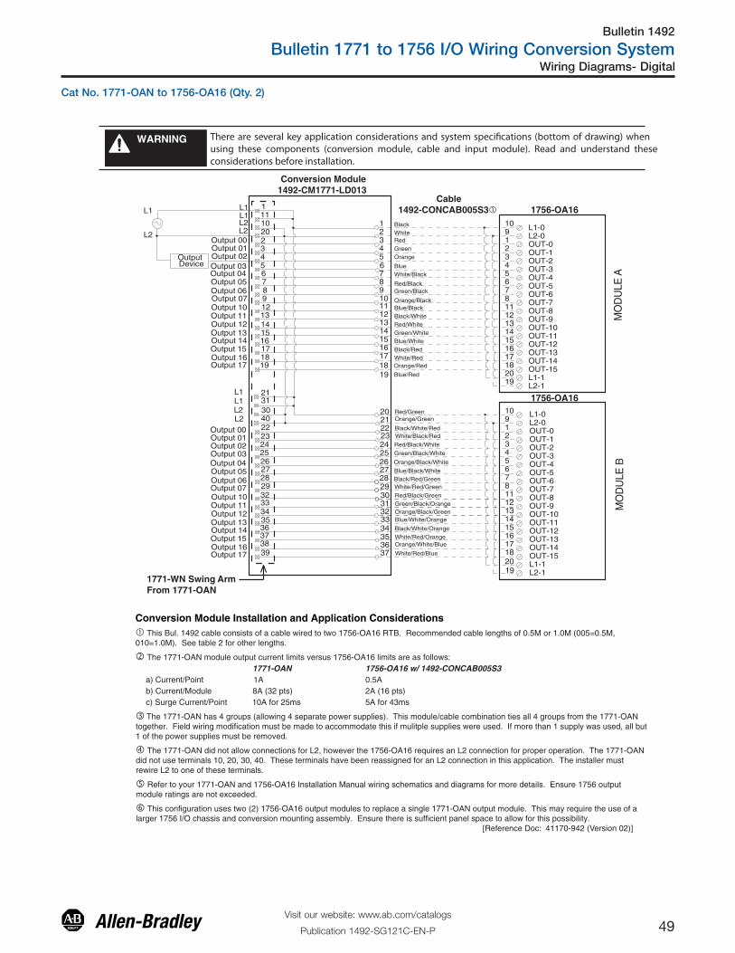
Bulletin 1492
Bulletin 1771 to 1756 I/O Wiring Conversion System
49Visit our website: www.ab.com/catalogs
Publication 1492-SG121C-EN-P
Wiring Diagrams- Digital
1771-WN Swing ArmFrom 1771-OAN
There are several key application considerations and system specifications (bottom of drawing) when using these components (conversion module, cable and input module). Read and understand these considerations before installation.
WARNING
1756-OA16
1756-OA16
Conversion Module1492-CM1771-LD013
Cable1492-CONCAB005S3�
Conversion Module Installation and Application Considerations� This Bul. 1492 cable consists of a cable wired to two 1756-OA16 RTB. Recommended cable lengths of 0.5M or 1.0M (005=0.5M, 010=1.0M). See table 2 for other lengths.
� The 1771-OAN module output current limits versus 1756-OA16 limits are as follows: 1771-OAN 1756-OA16 w/ 1492-CONCAB005S3a) Current/Point 1A 0.5Ab) Current/Module 8A (32 pts) 2A (16 pts)c) Surge Current/Point 10A for 25ms 5A for 43ms
� The 1771-OAN has 4 groups (allowing 4 separate power supplies). This module/cable combination ties all 4 groups from the 1771-OAN together. Field wiring modification must be made to accommodate this if mulitple supplies were used. If more than 1 supply was used, all but 1 of the power supplies must be removed.
� The 1771-OAN did not allow connections for L2, however the 1756-OA16 requires an L2 connection for proper operation. The 1771-OAN did not use terminals 10, 20, 30, 40. These terminals have been reassigned for an L2 connection in this application. The installer must rewire L2 to one of these terminals.
� Refer to your 1771-OAN and 1756-OA16 Installation Manual wiring schematics and diagrams for more details. Ensure 1756 output module ratings are not exceeded.
� This configuration uses two (2) 1756-OA16 output modules to replace a single 1771-OAN output module. This may require the use of a larger 1756 I/O chassis and conversion mounting assembly. Ensure there is sufficient panel space to allow for this possibility. [Reference Doc: 41170-942 (Version 02)]
10 L1-0L2-01 OUT-02 OUT-13 OUT-24
OUT-12
5
OUT-13
6
OUT-14
7
OUT-15
81112131415161718
BlackWhiteRedGreenOrange
BlueWhite/Black
Red/BlackGreen/Black
Orange/BlackBlue/BlackBlack/WhiteRed/WhiteGreen/WhiteBlue/WhiteBlack/RedWhite/Red
12345
78910
18
111213
151617
14
L1-119
9
OUT-3
20
L2-1
OUT-4OUT-5OUT-6OUT-7OUT-8OUT-9OUT-10OUT-11
10
123456781112131415161718
19
9
20
20 Red/Green21 Orange/Green
22 Black/White/Red
24 Red/Black/White
25 Green/Black/White
26 Orange/Black/White27 Blue/Black/White28 Black/Red/Green29 White/Red/Green
30 Red/Black/Green
31 Green/Black/Orange32 Orange/Black/Green33 Blue/White/Orange
34 Black/White/Orange
35 White/Red/Orange36
White/Red/Blue37
A EL
UD
OM
B EL
UD
OM
30
202
40
43
65
87
129
34
13
1
1615
1817
22
19
2423
2625
2827
3229
11
33
10L2L2
L2L2
Output 00Output 01Output 02Output 03Output 04Output 05Output 06Output 07Output 10Output 11
Output 13
Output 15
Output 12
Output 17
L1
35
31
14
L1
21L1
Output 14
Output 16
38
3637
39
L1
Output 00Output 01Output 02Output 03Output 04Output 05Output 06Output 07Output 10Output 11
Output 13
Output 15
Output 12
Output 17
Output 14
Output 16
Orange/Red
6
L1-0L2-0OUT-0OUT-1OUT-2
OUT-12OUT-13OUT-14OUT-15L1-1
OUT-3
L2-1
OUT-4OUT-5OUT-6OUT-7OUT-8OUT-9OUT-10OUT-11
23 White/Black/Red
Orange/White/Blue
L1
L2
OutputDevice
19 Blue/Red
Cat No. 1771-OAN to 1756-OA16 (Qty. 2)

Bulletin 1492
Bulletin 1771 to 1756 I/O Wiring Conversion System
50Visit our website: www.ab.com/catalogs
Publication 1492-SG121C-EN-P
Wiring Diagrams - Digital
1756-OB16D
There are several key application considerations and system specifications (bottom of drawing) when using these components (conversion module, cable and input module). Read and understand these considerations before installation.
WARNING
1771-WA Swing ArmFrom 1771-OB
1771-WA Swing ArmFrom 1771-OB Conversion Module
1492-CM1771-LD014
Conversion Module1492-CM1771-LD014 Cable
1492-C005005XF�
Conversion Module Installation and Application Considerations� This Bul. 1492 cable consists of 2 separate cables (cable “A” and cable “B”) wired to one 1756-OB16D RTB. Each cable can be either 0.5M or 1.0M (005=0.5M, 010=1.0M). Ensure that cable A and cable B are connected to the correct module in the conversion.
� The 1771-OB module output current limits versus 1756-OB16D limits are as follows: 1771-OB 1756-OB16D w/ 1492-C005005XFa) Current/Point 1.5A 2Ab) Current/Module 6A 4A @ 60°Cc) Surge Current/Point 4A for 8.3ms 4A for 10ms
� The 1771-OB has eight (8) 2A, 250V fuses - 1 per output. The 1756-OB16D is a DIAGNOSTIC MODULE. Refer to the 1756-OB16D Installation Manual for details on diagnostics.
� Refer to your 1771-OB and 1756-OB16D Installation Manual wiring schematics and diagrams for more details. Ensure 1756 output module ratings are not exceeded. [Reference Doc: 41170-988 (Version 00)]
B
3
4567
A012
Black
WhiteRed
Green
Orange
Blue
White/Black
Red/BlackGreen/Black
Orange/BlackBlue/Black
Black/White
Red/White
Green/White
Blue/White
Black/Red
White/Red
Orange/Red
Blue/Red
Red/Green
L1GND-0 OUT-0
1
OUT-13
OUT-25
OUT-37
OUT-4
2
OUT-5
4
OUT-6
6
OUT-7
8101214
9111315
GND-016
16
LOAD
-
+
+DC-0+DC-0+DC-0+DC-0+DC-0+DC-0+DC-0
1
19
345678910111213
15161718
20
14
2
24
212223
25
L2
Output 00Output 01Output 02Output 03
Output 04Output 05Output 06Output 07
B
3
4567
A012
Black
WhiteRed
Green
Orange
Blue
White/Black
Red/BlackGreen/Black
Orange/BlackBlue/Black
Black/White
Red/White
Green/White
Blue/White
Black/Red
White/Red
Orange/Red
Blue/Red
Red/Green
L1
OUT-817
OUT-919
OUT-1021
OUT-1123
OUT-12
18
OUT-13
20
OUT-14
22
OUT-15
2426283025272931
GND-132
32
LOAD
-
+
+DC-1+DC-1+DC-1+DC-1+DC-1+DC-1+DC-1
GND-1
1
19
345678910111213
15161718
20
14
2
24
212223
25
L2
Output 00Output 01Output 02Output 03
Output 04Output 05Output 06Output 07
GND-1
CABLE”A”
CABLE”B”
NOT USED
34
NOT USED33
NOT USED35
ONT USED36
Cat No. 1771-OB (Qty. 2) to 1756-OB16D

Bulletin 1492
Bulletin 1771 to 1756 I/O Wiring Conversion System
51Visit our website: www.ab.com/catalogs
Publication 1492-SG121C-EN-P
Wiring Diagrams- Digital
There are several key application considerations and system specifications (bottom of drawing) when using these components (conversion module, cable and input module). Read and understand these considerations before installation.
WARNING
1771-WH, WHF, WHFB Swing ArmFrom 1771-OBD
Conversion Module1492-CM1771-LD006
Cable1492-CONCAB005X� 1756-OB16E
Conversion Module Installation and Application Considerations� This Bul. 1492 cable consists of a cable wired to one 1756-OA16 RTB. Recommended cable lengths of 0.5M or 1.0M (005=0.5M, 010=1.0M). See table 2 for other lengths.
� The 1771-OBD module output current limits versus 1756-OB16E limits are as follows: 1771-OBD 1756-OB16E w/ 1492-CONCAB005X
a) Current/Point 2A 1Ab) Current/Module 8A 4Ac) Surge Current/point 4A for 10ms 2A for 10ms
� The 1771-OBD has a single 10A, 250V rectifier fuse (1/4 x 1 1/4 inch). The 1756-OB16E is electronically fused pergroup. Refer to the 1756-OB16E Installation Manual for details on electronic fusing.
� The 1771-OBD is rated 10V to 60V DC. The 1756-OB16E is rated 10V to 31.2V DC. If the load source voltage is greater than 30V DC, then use the 1756-OC8 with the 1492-CM1771-LD008F conversion module.
� Refer to your 1771-OBD and 1756-OB16E Installation Manual wiring schematics and diagrams for more details. Ensure 1756 output module ratings are not exceeded. [Reference Doc: 41170-936 (Version 01)]
+
+
-
-
10DC-0+
OUT-01
OUT-12
OUT-23
OUT-34
OUT-45
OUT-56
OUT-67
OUT-78
OUT-811
OUT-912
OUT-1013
OUT-1114
OUT-1215
OUT-1316
OUT-1417
OUT-1518
Black
White
Red
Green
Orange
Blue
White/Black
Red/Black
Green/Black
Orange/Black
Blue/Black
Black/White
Red/White
Green/White
Blue/White
Black/Red
White/Red
Orange/Red
Blue/Red
Red/GreenDC-1+
20
9RTN OUT-0
19RTN OUT-1
A
1
00
19
013
024
035
046
057
068
079
E
10111012111312
13151416151716
17 18
20
14
2
Output 14
Output 16Output 15
Output 17
Output 04
Output 06
dc OutputDevice
Output 05
Output 07
Output 00
Output 02Output 01
Output 03
Output 10
Output 12Output 11
Output 13
+ dc
L2
BCD
+ dc+ dc+ dc
24
212223
25
Cat No. 1771-OBD to 1756-OB16E

Bulletin 1492
Bulletin 1771 to 1756 I/O Wiring Conversion System
52Visit our website: www.ab.com/catalogs
Publication 1492-SG121C-EN-P
Wiring Diagrams - Digital
Conversion Module Installation and Application Considerations� This Bul. 1492 cable consists of a cable wired to two 1756-OC8 RTB. Recommended cable lengths of 0.5M or 1.0M (005=0.5M, 010=1.0M). See table 2 for other lengths.
� The 1771-OBD module output current limits versus 1756-OC8 limits are as follows: 1771-OBD 1756-OC8 w/ 1492-CONCAB005S1a) Current/Point 2A 2Ab) Current /Module 8A 8Ac) Surge Current /Point 4A for 10ms 4A for 10ms
� The 1771-OBD has a single 10A, 250V rectifier fuse (1/4 x 1 1/4 inch ). The 1756-OC8 is NOT fused ,as such a2AG fuse clip and 10A fuse is provided on the 1492-CM1771-LD008F conversion module.
� The 1771-OBD is rated 10V to 60V DC. The 1756-OC8 is rated 30V to 60V DC. If the load source voltages is lessthan 30V DC, then use 1756-OB16E with the 1492-CM1771-LD006 conversion module.
� This configuration uses two(2) 1756-OC8 output modules to replace a single 1771-OBD output module. This may requirethe use of a larger 1756 I/O chassis and conversion mounting assembly. Ensure there is sufficient panel space to allow forthis possibility.
� Refer to your 1771-OBD and 1756-OC8 Installation Manual wiring schematics and diagrams for more details. Ensure1756 output module ratings are not exceeded. [Reference Doc: 41170-937 (Version 01)]
There are several key application considerations and system specifications (bottom of drawing) when using these components (conversion module, cable and input module). Read and understand these considerations before installation.
WARNING
1
2
3
4
5
67891011121314151617
18
1920212223
242526272829303132333435
3736
ABCD
010203040506071011121314151617
00
DC(+)
DC(-)
DC(+)DC(+)DC(+)
E
LOAD
+
- Output 01Output 02Output 03Output 04Output 05Output 06Output 07Output 10Output 11Output 12Output 13Output 14Output 15Output 16Output 17
Output 00
1771-WH, WHF, WHFB Swing ArmFrom 1771-OBD
Green/Black/Orange
Orange/Black/Green
Blue/White/Orange
Black/White/Orange
White/Red/Orange
White/Red/Blue
Orange/Green
Black/White/Red
White/Black/Red
Red/Black/White
Green/Black/White
Orange/Black/White
Blue/Black/White
Black/Red/Green
White/Red/Green
Red/Black/Green
Black
White
Red
Green
Orange
Blue
White/Black
Red/Black
Green/Black
Orange/Black
Blue/Black
Black/White
Red/White
Green/White
Blue/White
Black/Red
White/Red
Orange/Red
Blue/Red
Red/Green
1
3
5
7
468101214161811131517
20
21357
468101214161811131517
2019
9
19
9
DC-0(+)
OUT-0
OUT-1
OUT-2
OUT-3
DC-0(+)DC-0(+)DC-0(+)RTN OUT-0DC-1(+)DC-1(+)DC-1(+)DC-1(+)OUT-4OUT-5OUT-6OUT-7
RTN OUT-1
DC-0(+)OUT-0OUT-1OUT-2OUT-3
DC-0(+)DC-0(+)DC-0(+)RTN OUT-0DC-1(+)DC-1(+)DC-1(+)DC-1(+)OUT-4OUT-5OUT-6OUT-7
RTN OUT-1RTN OUT-1
RTN OUT-0
RTN OUT-1
RTN OUT-0
2
MO
DU
LE B
MO
DU
LE A
Conversion Module1492-CM1771-LD008F
Cable1492-CONCAB005S1� 1756-OC8
1756-OC8
Cat No. 1771-OBD to 1756-OB8 (Qty. 2)

Bulletin 1492
Bulletin 1771 to 1756 I/O Wiring Conversion System
53Visit our website: www.ab.com/catalogs
Publication 1492-SG121C-EN-P
Wiring Diagrams- Digital
There are several key application considerations and system specifications (bottom of drawing) when using these components (conversion module, cable and input module). Read and understand these considerations before installation.
WARNING
1771-WH, WHF, WHFB Swing ArmFrom 1171-OBDS
� This Bul. 1492 cable consists of a cable wired to one 1756-OB16E RTB. Recommended cable lengths of 0.5M or 1.0M (005=0.5M, 010=1.0M). See table 2 for other lengths.
� The 1771-OBDS module output current limits versus 1756-OB16E limits are as follows: 1771-OBDS 1756-OB16E w/ 1492-CONCAB005Xa) Current/Point 1A 1Ab) Current/Module 8A 8Ac) Surge Current/Point 4A for 10ms 2A for 10ms
� The 1771-OBDS has a single 12A, 250V rectifier fuse (1/4 x 1-1/4 inch). The 1756-OB16E is electronically fused per group. Refer to the 1756-OB16E Installation Manual for details on electronic fusing.
� The 1771-OBDS is rated 10V to 40V DC. The 1756-OB16E is rated 10V to 31.2V DC. If the load source voltage is greaterthan 30V DC, then use the 1756-OC8 with the 1492-CM1771-LD008F conversion module.
� Refer to your 1771-OBDS and 1756-OB16E Installation Manual wiring schematics and diagrams for more details. Ensure1756 output module ratings are not exceeded. [Reference Doc: 41171-005 (Version 00)]
Conversion Module Installation and Application Considerations
Conversion Module1492-CM1771-LD006
Cable1492-CONCAB005X� 1756-OB16E
10DC-0+
OUT-01
OUT-12
OUT-23
OUT-34
OUT-45
OUT-56
OUT-67
OUT-78
OUT-811
OUT-912
OUT-1013
OUT-1114
OUT-1215
OUT-1316
OUT-1417
OUT-1518
Black
WhiteRed
Green
Orange
Blue
White/Black
Red/BlackGreen/Black
Orange/BlackBlue/Black
Black/White
Red/White
Green/White
Blue/White
Black/Red
White/Red
Orange/Red
Blue/Red
Red/GreenDC-1+
20
9RTN OUT-0
19RTN OUT-1
A
1
00
19
013
024
035
046
057
068
079
E
10111012111312
13151416151716
17 18
20
14
2
Output 00
+ dc
- dc
B
CD
dc OutputDevice
Output 01Output 02Output 03Output 04Output 05Output 06Output 07Output 10
Output 11Output 12Output 13Output 14Output 15Output 16Output 17
+
-
+-
+ dc
+ dc
+ dc
24
212223
25
Cat No. 1771-OBDS to 1756-16E

Bulletin 1492
Bulletin 1771 to 1756 I/O Wiring Conversion System
54Visit our website: www.ab.com/catalogs
Publication 1492-SG121C-EN-P
Wiring Diagrams - Digital
Conversion Module Installation and Application Considerations �The 1771-OBN module output current limits versus 1756-OB32 limits are as follows: 1771-OBN 1756-OB32w/1492-CONCAB005Za) Current/Point 0.5A 0.35A @ 60˚Cb) Current/Module 8A 6A @ 60˚Cc) Surge Current/Point 2A for 10ms 1A for 10ms� The 1771-OBN has four (4) 4A, 250V rectifier fuses. The 1756-OB32 is NOT fused, as such four (4) 2AG fuse clips and 4A fuses are provided on the 1492-CM1771-LD009F conversion module.� The 1492-CONAB005Z is limited to 3A per pin.� The 1771-OBN has 4 groups (allowing 4 separate power supplies) and the 1756-OB32 has 2 groups. This module/cable combination ties Groups 0 & 1 from the 1771-OBN to Group 0 on the 1756-OB32 and Groups 2 & 3 from the 1771-OBN to Group 1 on the 1756-OB32. Field wiring modification must be made to accommodate this if multiple supplies were used. If 4 supplies were used, 2 must be removed.� Refer to your 1771-OBN and 1756-OB32 Installation Manual wiring schematics and diagrams for more details. Ensure 1756 output module ratings are not exceeded. [Reference Doc: 41170-938 (Version 01)]
There are several key application considerations and system specifications (bottom of drawing) when using these components (conversion module, cable and input module). Read and understand these considerations before installation.
WARNING
12
345678910
1112131415161718192021222324
25262728293031323334353637
Black
White
Red
Green
Orange
Blue
White/Black
Red/Black
Green/Black
Orange/Black
Blue/Black
Black/White
Red/White
Green/White
Blue/White
Black/Red
White/Red
Orange/Red
Blue/Red
Red/Green
Orange/Green
Black/White/Red
White/Black/Red
Red/Black/White
Green/Black/White
Orange/Black/White
Blue/Black/White
Black/Red/Green
White/Red/Orange
Red/Black/Green
Green/Black/Orange
Orange/Black/Green
Blue/White/Orange
Black/White/OrangeWhite/Red/Orange
Orange/White/Blue
White/Red/Blue
LOAD
+
-
10-30V dc(0)10-30V dc(1)10-30V dc(2)10-30V dc(3)
1836
11922032142252362472582692710281129123013311432153316341735
11121312223234245256267278289291232133314341535163617371838193910203040
DC-0(+)DC-1(+)
OUT-0OUT-16OUT-1OUT-17OUT-2OUT-18OUT-3OUT-19OUT-4OUT-20OUT-5OUT-21OUT-6OUT-22OUT-7OUT-23OUT-8OUT-24OUT-9OUT-25OUT-10OUT-26OUT-11OUT-27OUT-12OUT-28OUT-13OUT-29OUT-14OUT-30OUT-15OUT-31RTN OUT-0RTN OUT-1
Output 00Output 00Output 01Output 01Output 02Output 02Output 03Output 03Output 04Output 04Output 05Output 05Output 06Output 06Output 07Output 07Output 10Output 10Output 11Output 11Output 12Output 12Output 13Output 13Output 14Output 14Output 15Output 15Output 16Output 16Output 17Output 17Common 0Common 1Common 2Common 3
Conversion Module1492-CM1771-LD009F
Cable1492-CONCAB005Z� 1756-OB32
1771-WN Swing ArmFrom 1771-OBN
Cat No. 1771-OBN to 1756-OB32
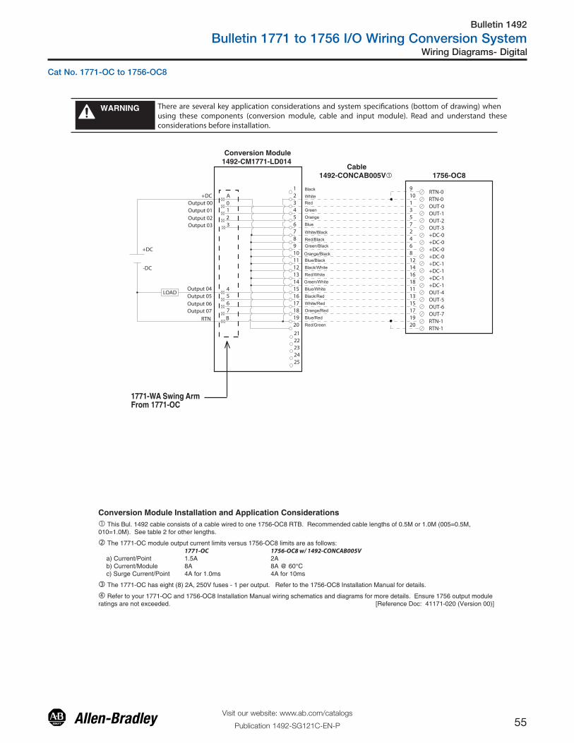
Bulletin 1492
Bulletin 1771 to 1756 I/O Wiring Conversion System
55Visit our website: www.ab.com/catalogs
Publication 1492-SG121C-EN-P
Wiring Diagrams- Digital
There are several key application considerations and system specifications (bottom of drawing) when using these components (conversion module, cable and input module). Read and understand these considerations before installation.
WARNING
1771-WA Swing ArmFrom 1771-OC
1756-OC8
Conversion Module1492-CM1771-LD014
Cable1492-CONCAB005V�
Conversion Module Installation and Application Considerations� This Bul. 1492 cable consists of a cable wired to one 1756-OC8 RTB. Recommended cable lengths of 0.5M or 1.0M (005=0.5M, 010=1.0M). See table 2 for other lengths.
� The 1771-OC module output current limits versus 1756-OC8 limits are as follows: 1771-OC 1756-OC8 w/ 1492-CONCAB005Va) Current/Point 1.5A 2Ab) Current/Module 8A 8A @ 60°Cc) Surge Current/Point 4A for 1.0ms 4A for 10ms
� The 1771-OC has eight (8) 2A, 250V fuses - 1 per output. Refer to the 1756-OC8 Installation Manual for details.
� Refer to your 1771-OC and 1756-OC8 Installation Manual wiring schematics and diagrams for more details. Ensure 1756 output module ratings are not exceeded. [Reference Doc: 41171-020 (Version 00)]
B
3
4567
A012
Black
WhiteRed
Green
Orange
Blue
White/Black
Red/BlackGreen/Black
Orange/BlackBlue/Black
Black/White
Red/White
Green/White
Blue/White
Black/Red
White/Red
Orange/Red
Blue/Red
Red/Green
+DC9
RTN-0OUT-0
1
OUT-13
OUT-25
OUT-37
OUT-4
2
OUT-5
4
OUT-6
6
OUT-7
81214161811131517
RTN-119
10
20RTN-1
LOAD
-DC
+DC
+DC-0+DC-0+DC-0+DC-0+DC-1+DC-1+DC-1+DC-1
1
19
345678910111213
15161718
20
14
2
24
212223
25
RTN
Output 00Output 01Output 02Output 03
Output 04Output 05Output 06Output 07
RTN-0
Cat No. 1771-OC to 1756-OC8
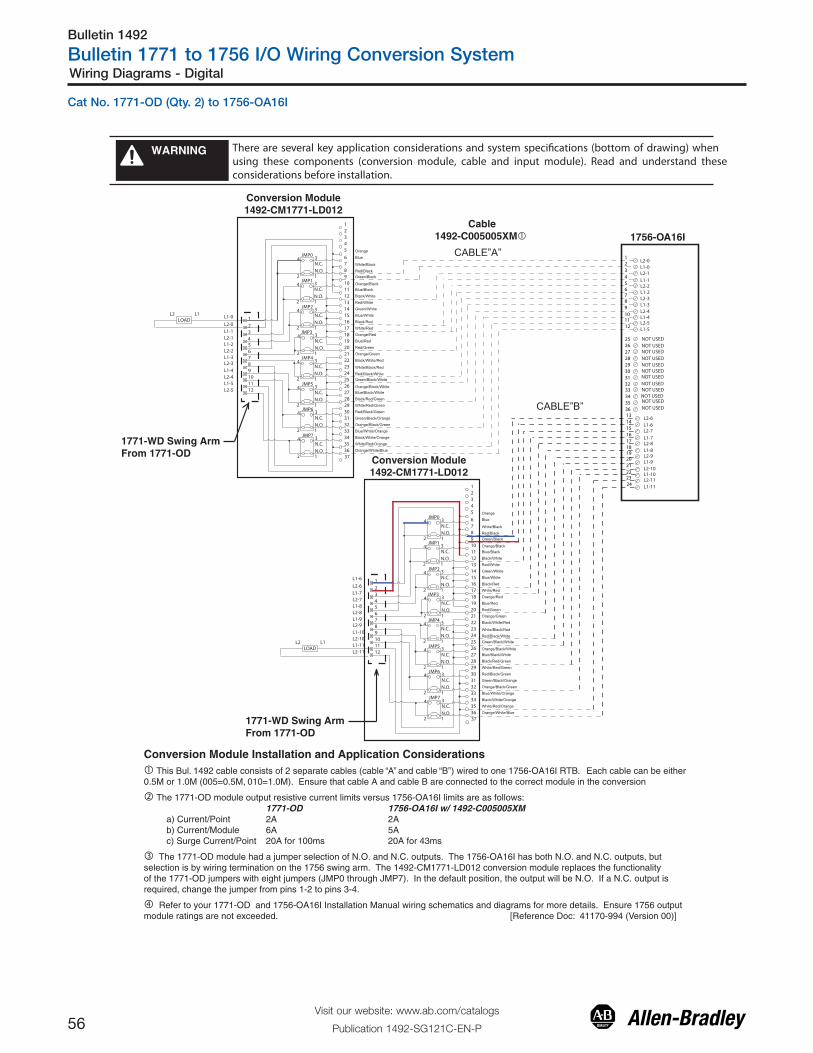
Bulletin 1492
Bulletin 1771 to 1756 I/O Wiring Conversion System
56Visit our website: www.ab.com/catalogs
Publication 1492-SG121C-EN-P
Wiring Diagrams - Digital
There are several key application considerations and system specifications (bottom of drawing) when using these components (conversion module, cable and input module). Read and understand these considerations before installation.
WARNING
Conversion Module1492-CM1771-LD012
Conversion Module1492-CM1771-LD012
1771-WD Swing ArmFrom 1771-OD
1771-WD Swing ArmFrom 1771-OD
Cable1492-C005005XM� 1756-OA16I
Conversion Module Installation and Application Considerations� This Bul. 1492 cable consists of 2 separate cables (cable “A” and cable “B”) wired to one 1756-OA16I RTB. Each cable can be either0.5M or 1.0M (005=0.5M, 010=1.0M). Ensure that cable A and cable B are connected to the correct module in the conversion
� The 1771-OD module output resistive current limits versus 1756-OA16I limits are as follows: 1771-OD 1756-OA16I w/ 1492-C005005XM a) Current/Point 2A 2A b) Current/Module 6A 5A c) Surge Current/Point 20A for 100ms 20A for 43ms
� The 1771-OD module had a jumper selection of N.O. and N.C. outputs. The 1756-OA16I has both N.O. and N.C. outputs, but selection is by wiring termination on the 1756 swing arm. The 1492-CM1771-LD012 conversion module replaces the functionalityof the 1771-OD jumpers with eight jumpers (JMP0 through JMP7). In the default position, the output will be N.O. If a N.C. output isrequired, change the jumper from pins 1-2 to pins 3-4.
� Refer to your 1771-OD and 1756-OA16I Installation Manual wiring schematics and diagrams for more details. Ensure 1756 output module ratings are not exceeded. [Reference Doc: 41170-994 (Version 00)]
12345
678910111213
151617181920
14
21222324252627282930313233
353637
34
LOAD
123456
Orange
Blue
White/Black
Red/BlackGreen/Black
Orange/BlackBlue/Black
Black/White
Red/White
Green/White
Blue/White
Black/Red
White/Red
Orange/Red
Blue/Red
Red/Green
7891011
Orange/Green
Black/White/Red
White/Black/Red
Red/Black/WhiteGreen/Black/White
Orange/Black/WhiteBlue/Black/White
Black/Red/Green
White/Red/Green
Red/Black/Green
Green/Black/Orange
Orange/Black/Green
Blue/White/Orange
Black/White/Orange
White/Red/Orange
Orange/White/Blue
12
L1L21
56789101112
234
1
3
2
4
N.O.
N.C.
1
3
2
4
N.O.
N.C.
JMP0
JMP1
1
3
2
4
N.O.
N.C.
JMP2
1
3
2
4
N.O.
N.C.
1
3
2
4
N.O.
N.C.
JMP3
JMP4
1
3
2
4
N.O.
N.C.
JMP5
1
3
2
4
N.O.
N.C.
JMP6
1
3
2
4
N.O.
N.C.
JMP7
12345
678910111213
151617181920
14
21222324252627282930313233
353637
34
Orange
Blue
White/Black
Red/BlackGreen/Black
Orange/BlackBlue/Black
Black/White
Red/White
Green/White
Blue/White
Black/Red
White/Red
Orange/Red
Blue/Red
Red/Green
Orange/Green
Black/White/Red
White/Black/Red
Red/Black/WhiteGreen/Black/White
Orange/Black/WhiteBlue/Black/White
Black/Red/Green
White/Red/Green
Red/Black/Green
Green/Black/Orange
Orange/Black/Green
Blue/White/Orange
Black/White/Orange
White/Red/Orange
Orange/White/Blue
1
56789101112
234
1
3
2
4
N.O.
N.C.
1
3
2
4
N.O.
N.C.
JMP0
JMP1
1
3
2
4
N.O.
N.C.
JMP2
1
3
2
4
N.O.
N.C.
1
3
2
4
N.O.
N.C.
JMP3
JMP4
1
3
2
4
N.O.
N.C.
JMP5
1
3
2
4
N.O.
N.C.
JMP6
1
3
2
4
N.O.
N.C.
JMP7
252627282930313233343536
NOT USED
NOT USEDNOT USED
131415161718192021222324
L2-6L1-6L2-7
L1-7L2-8L1-8
L1-9L2-9
L1-10L2-10
L2-11L1-11
NOT USEDNOT USEDNOT USEDNOT USEDNOT USEDNOT USEDNOT USEDNOT USED
L1-0
L2-0
L1-1L2-1L1-2L2-2
L2-3L1-3
L2-4L1-4
L1-5L2-5
LOADL1L2
L1-6
L2-6
L1-7L2-7L1-8L2-8
L2-9L1-9
L2-10L1-10
L1-11L2-11
L2-0L1-0L2-1L1-1L2-2L1-2
L1-3L2-3
L1-4L2-4
L2-5L1-5
CABLE”A”
CABLE”B”NOT USED
Cat No. 1771-OD (Qty. 2) to 1756-OA16I

Bulletin 1492
Bulletin 1771 to 1756 I/O Wiring Conversion System
57Visit our website: www.ab.com/catalogs
Publication 1492-SG121C-EN-P
Wiring Diagrams- Digital
There are several key application considerations and system specifications (bottom of drawing) when using these components (conversion module, cable and input module). Read and understand these considerations before installation.
WARNING
Conversion Module Installation and Application Considerations � This Bul. 1492 cable consists of a cable wired to one 1756-OA16I RTB. Recommended cable lengths of 0.5M or 1.0M (005=0.5M, 010=1.0M). See table 2 for other lengths.
� The 1771-OD16 module output current limits versus 1756-OA16I limits are as follows: 1771-OD16 1756-OA16I w/ 1492-CONCAB005Ya) Current/Point 2A 1Ab) Current/Module 8A 4Ab) Surge Current/Point 20A for 100ms 20A for 43ms
� The 1771-OD16 has sixteen (16) 3A ,250V recifier fuses. The 1756-OA16I is NOT fused,as such sixteen (16) 2AG fuseclips are provided on the 1492-CM1771-LD010F conversion module. Max fuse rating is 1.5A based on 1756-OA16I.
� The 1771-OD16 is rated 74V to 138V AC and 105V to 138V DC. The 1756-OA16I is rated 74V to 265V AC. A1756 isolated output module with an equivalent DC voltage range to convert the1771 -OD16 is not available.
� Refer to your 1771-OD16 and 1756-OA16I Installation Manual wiring schematics and diagrams for more details. Ensure 1756 output module rating are not exceeded. [Reference Doc: 41170-939 (Version 01)]
10 9
19202143
6 5 8 712111413161518172221242326252827323134333635383729303940
Output 10
Output 12
Output 11
Output 13
Output 2
Output 4
Output 3
Output 5
Not Used
Output 0
Not Used
Output 1
Output 6
Output 8
Output 7
Output 9
L1-14 Output 14
L1-15 Output 15
Not usedNot usedNot usedNot used
12345678910111213
151617181920
14
21222324252627282930313233
353637
34
OUT-0
21
OUT-1
43
OUT-2
65
OUT-3
87
OUT-4
109
OUT-5
1211
OUT-6
1413
Orange
Blue
White/Black
Red/BlackGreen/Black
Orange/BlackBlue/Black
Black/White
Red/White
Green/White
Blue/White
Black/Red
White/Red
Orange/Red
Blue/Red
Red/GreenOUT-7
1615
OUT-8
1817
OUT-9
2019
OUT-10
2221
OUT-11
2423
OUT-12
2625
OUT-13
2827
OUT-14
3029
Orange/Green
Black/White/Red
White/Black/Red
Red/Black/WhiteGreen/Black/White
Orange/Black/WhiteBlue/Black/White
Black/Red/Green
White/Red/Green
Red/Black/Green
Green/Black/Orange
Orange/Black/Green
Blue/White/Orange
Black/White/Orange
White/Red/Orange
Orange/White/BlueOUT-15
3231
L1-0
L1-1
L1-2
L1-3
L1-4
L1-5
L1-6
L1-7
L1-8
L1-9
L1-10
L1-11
L1-12
L1-13
L1-14
L1-15
L2
Not Used
Not Used
L1-0
L1-1
L1-2
L1-3
L1-4
L1-5
L1-6
L1-7
L1-8
L1-9
L1-10
L1-11
L1-12
L1-13
LOADL1
1771-WN Swing ArmFrom 1771-OD16
Conversion Module1492-CM1771-LD010F
1756-OA16I Cable
1492-CONCAB005Y�
Cat No. 1771-OD16 to 1756-OA16I

Bulletin 1492
Bulletin 1771 to 1756 I/O Wiring Conversion System
58Visit our website: www.ab.com/catalogs
Publication 1492-SG121C-EN-P
Wiring Diagrams - Digital
There are several key application considerations and system specifications (bottom of drawing) when using these components (conversion module, cable and input module). Read and understand these considerations before installation.
WARNING
Conversion Module Installation and Application Considerations� This Bul. 1492 cable consists of a cable wired to one 1756-OA16I RTB. Recommended cable lengths of 0.5M or 1.0M (005=0.5M, 010=1.0M). See table 2 for other lengths.
� The 1771-ODD module output current limits versus 1756-OA16I limits are as follows: 1771-ODD 1756-OA16I w/ 1492-CONCAB005Ya) Current/Point 2A 2Ab) Current/Module 8A 5Ac) Surge Current/Point 20A for 100ms 20A for 43ms
� The 1771-ODD has sixteen (16) 3A, 250V rectifier fuses. The 1756-OA16I is NOT fused, as such sixteen(16) 2AG fuses and clips are provided on the 1492-CM1771-LD010F conversion module. Max fuse rating is 1.5A based on 1756-OA16I.
� The 1771-ODD is rated 74V to 138V AC. The 1756-OA16I is rated 74V to 265V AC.
� Refer to your 1771-ODD and 1756-OA16I Installation Manual wiring schematics and diagrams for more details. Ensure 1756 output module ratings are not exceeded. [Reference Doc: 41171-009 (Version 00)]
12345678910111213
151617181920
14
21222324252627282930313233
353637
34
OUT-0
21
OUT-1
43
OUT-2
65
OUT-3
87
OUT-4
109
OUT-5
1211
OUT-6
1413
Orange
Blue
White/Black
Red/BlackGreen/Black
Orange/BlackBlue/Black
Black/White
Red/White
Green/White
Blue/White
Black/Red
White/Red
Orange/Red
Blue/Red
Red/GreenOUT-7
1615
OUT-8
1817
OUT-9
2019
OUT-10
2221
OUT-11
2423
OUT-12
2625
OUT-13
2827
OUT-14
3029
Orange/Green
Black/White/Red
White/Black/Red
Red/Black/WhiteGreen/Black/White
Orange/Black/WhiteBlue/Black/White
Black/Red/Green
White/Red/Green
Red/Black/Green
Green/Black/Orange
Orange/Black/Green
Blue/White/Orange
Black/White/Orange
White/Red/Orange
Orange/White/BlueOUT-15
3231
L1-0
L1-1
L1-2
L1-3
L1-4
L1-5
L1-6
L1-7
L1-8
L1-9
L1-10
L1-11
L1-12
L1-13
L1-14
L1-15
LOADL1
L2
40
21Ouput 0
3Ouput 1
5Ouput 2
7Ouput 3
11Ouput 4
13Ouput 5
15Ouput 6
17Ouput 7
21Ouput 8
23Ouput 9
25Ouput 10
27Ouput 11
31Ouput 12
33Ouput 13
35Ouput 14
37Ouput 15
L1-0
L1-1
L1-2
L1-3
L1-4
L1-5
L1-6
L1-7
L1-8
L1-9
L1-10
L1-11
L1-12
L1-13
L1-14
L1-15
4
6
8
29
12
14
16
18
30
22
24
26
28
39
32
34
36
38
910
20
19
Not Used
Not UsedNot UsedNot Used
Not Used
Not UsedNot UsedNot Used
1771-WH Swing ArmFrom 1771-ODD
1756-OA16I
Conversion Module1492-CM1771-LD010F
Cable1492-CONCAB005Y�
Cat No. 1771-ODD to 1756-OA16I

Bulletin 1492
Bulletin 1771 to 1756 I/O Wiring Conversion System
59Visit our website: www.ab.com/catalogs
Publication 1492-SG121C-EN-P
Wiring Diagrams- Digital
Conversion Module1492-CM1771-LD012
Conversion Module1492-CM1771-LD012
1771-WD Swing ArmFrom 1771-ODZ
1771-WD Swing ArmFrom 1771-ODZ
Cable1492-C005005XP� 1756-OA16I
There are several key application considerations and system specifications (bottom of drawing) when using these components (conversion module, cable and input module). Read and understand these considerations before installation.
WARNING
Conversion Module Installation and Application Considerations� This Bul. 1492 cable consists of 2 separate cables (cable “A” and cable “B”) wired to one 1756-OA16I RTB. Each cable can be either0.5M or 1.0M (005=0.5M, 010=1.0M). Ensure that cable A and cable B are connected to the correct module in the conversion
� The 1771-ODZ module output resistive current limits versus 1756-OA16I limits are as follows: 1771-ODZ 1756-OA16I w/ 1492-C005005XP a) Current/Point 2A 2A b) Current/Module 6A 5A @ 60°C c) Surge Current/Point 20A for 100ms 20A for 43ms
� The 1771-ODZ module had a jumper selection of N.O. and N.C. outputs. The 1756-OA16I has both N.O. and N.C. outputs, but selection is by wiring termination on the 1756 swing arm. The 1492-CM1771-LD012 conversion module replaces the functionalityof the 1771-ODZ jumpers with eight jumpers (JMP0 through JMP7). In the default position, the output will be N.O. If a N.C. output isrequired, change the jumper from pins 1-2 to pins 3-4.
� Refer to your 1771-ODZ and 1756-OA16I Installation Manual wiring schematics and diagrams for more details. Ensure 1756 output module ratings are not exceeded. [Reference Doc: 41171-016 (Version 00)]
2
8
1
4
16
6
5710
912
11
33343536
NOT USED
NOT USEDNOT USED
L1-0L1-0L2-0L2-1
L1-1L1-1
L2-3L2-2
L2-4
L1-2L1-2
L2-5
CABLE”A”
NOT USED
12345
678910111213
151617181920
14
21222324252627282930313233
353637
34
LOAD
1492-CONCAB005Y
Orange
Blue
White/Black
Red/BlackGreen/Black
Orange/BlackBlue/Black
Black/White
Red/White
Green/White
Blue/White
Black/Red
White/Red
Orange/Red
Blue/Red
Red/Green
Orange/Green
Black/White/Red
White/Black/Red
Red/Black/WhiteGreen/Black/White
Orange/Black/WhiteBlue/Black/White
Black/Red/Green
White/Red/Green
Red/Black/Green
Green/Black/Orange
Orange/Black/Green
Blue/White/Orange
Black/White/Orange
White/Red/Orange
Orange/White/Blue
L1
L2
+
- LOAD
1
56789101112
+V0/1
Out-0 N.O./N.C.
234
Out-1 N.O./N.C.
+V2/3
Out-2 N.O./N.C.
Out-3 N.O./N.C.
+V4/5
Out-4 N.O./N.C.
Out-5 N.O./N.C.
+V6/7
Out-6 N.O./N.C.
Out-7 N.O./N.C.
1
3
2
4
N.O.
N.C.
1
3
2
4
N.O.
N.C.
JMP0
JMP1
1
3
2
4
N.O.
N.C.
JMP2
1
3
2
4
N.O.
N.C.
1
3
2
4
N.O.
N.C.
JMP3
JMP4
1
3
2
4
N.O.
N.C.
JMP5
1
3
2
4
N.O.
N.C.
JMP6
1
3
2
4
N.O.
N.C.
JMP7
14
1315
L1-3
L2-6L2-7
12345
678910111213
151617181920
14
21222324252627282930313233
353637
34
LOAD
Orange
Blue
White/Black
Red/BlackGreen/Black
Orange/BlackBlue/Black
Black/White
Red/White
Green/White
Blue/White
Black/Red
White/Red
Orange/Red
Blue/Red
Red/Green
Orange/Green
Black/White/Red
White/Black/Red
Red/Black/WhiteGreen/Black/White
Orange/Black/WhiteBlue/Black/White
Black/Red/Green
White/Red/Green
Red/Black/Green
Green/Black/Orange
Orange/Black/Green
Blue/White/Orange
Black/White/Orange
White/Red/Orange
Orange/White/Blue
L1
L2
+
- LOAD
1
56789101112
+V0/1
Out-0 N.O./N.C.
234
Out-1 N.O./N.C.
+V2/3
Out-2 N.O./N.C.
Out-3 N.O./N.C.
+V4/5
Out-4 N.O./N.C.
Out-5 N.O./N.C.
+V6/7
Out-6 N.O./N.C.
Out-7 N.O./N.C.
1
3
2
4
N.O.
N.C.
1
3
2
4
N.O.
N.C.
JMP0
JMP1
1
3
2
4
N.O.
N.C.
JMP2
1
3
2
4
N.O.
N.C.
1
3
2
4
N.O.
N.C.
JMP3
JMP4
1
3
2
4
N.O.
N.C.
JMP5
1
3
2
4
N.O.
N.C.
JMP6
1
3
2
4
N.O.
N.C.
JMP7
L1-4L1-4L2-8L2-9L1-5L1-5
L2-11L2-10
L1-6L1-4
L2-12L2-13
L1-7L1-7
L2-14L2-15
3
L1-3
CABLE”B”18
24
17
20
32
22
212326
2528
27
30
2931
19
Cat No. 1771-ODZ (Qty. 2) to 1756-OA16I

Bulletin 1492
Bulletin 1771 to 1756 I/O Wiring Conversion System
60Visit our website: www.ab.com/catalogs
Publication 1492-SG121C-EN-P
Wiring Diagrams - Digital
There are several key application considerations and system specifications (bottom of drawing) when using these components (conversion module, cable and input module). Read and understand these considerations before installation.
WARNING
1771-WC Swing ArmFrom 1771-OG
1771-WC Swing ArmFrom 1771-OG
Conversion Module1492-CM1771-LA003
Conversion Module1492-CM1771-LA003
Cable1492-C005005XS� 1756-OG16
OutputDevice
1325242322211918171612
SH
Output 0 + DC 10
OUT-0OUT-1
1
OUT-2
234567
98
Red/White
Green/Black/White
Black/White/Red
White/Black/Red
Orange/Green
Red/Black/White
Orange/Red
Blue/Red
+ -
A
34567B
012
Common
Output 1 Output 2 Output 3 Output 4 Output 5 Output 6 Output 7
3456789101112141520
OUT-3OUT-4OUT-5OUT-6OUT-7
+ DC -0
- DC -020
OUT-8OUT-9OUT-10OUT-11OUT-12OUT-13OUT-14OUT-15
+ DC -1
- DC -1
1325242322211918171612
SH
Red/White
Green/Black/White
Black/White/Red
White/Black/Red
Orange/Green
Red/Black/White
Orange/Red
Blue/Red
A
34567B
012
3456789101112141520
Output 8 + DC
Common
Output 9 Output 10 Output 11 Output 12 Output 13 Output 14 Output 15
111213141516171819
Black/Red
White/Red
Black/Red
White/Red
CABLE”B”
+
- 5V DCSUPPLY
OutputDevice
+ -
+
- 5V DCSUPPLY
Conversion Module Installation and Application Considerations � This Bul. 1492 cable consists of 2 separate cables (cable “A” and cable “B”) wired to one 1756-OG16 RTB. Each cable can be either 0.5M or 1.0M (005=0.5M, 010=1.0M). Ensure that cable A and cable B are connected to the correct module in the conversion.
� The input delay times for the 1771-OG module versus the 1756-OG16 module are as follows: 1771-OG 1756-OG16 w/ 1492-C005005XS a) Off-to-On Delay 1ms (+/-10ms) 45ms max (plus selectable filter) b) On-to-Off Delay 1ms (+/-10ms) 145ms max (plus selectable filter)
� The 1771-OG module is rated 5V DC TTL INPUT MODULE. The 1756-OG16 module is rated 5V DC TTL INPUT MODULE only.
� Refer to your 1771-OG and 1756-OG16 Installation and User Manuals for additional information concerning comparisons of module wiring, features and configuration details. [Reference Doc: 41171-028 (Version 00)]
CABLE”A”
Cat No. 1771-OG (Qty. 2) to 1756-OG16

Bulletin 1492
Bulletin 1771 to 1756 I/O Wiring Conversion System
61Visit our website: www.ab.com/catalogs
Publication 1492-SG121C-EN-P
Wiring Diagrams- Digital
There are several key application considerations and system specifications (bottom of drawing) when using these components (conversion module, cable and input module). Read and understand these considerations before installation.
WARNING
1771-WH, WHF, WHFB Swing ArmFrom 1171-OGD
� This Bul. 1492 cable consists of a cable wired to one 1756-OG16 RTB. Recommended cable lengths of 0.5M or 1.0M (005=0.5M, 010=1.0M). See table 2 for other lengths.
� The 1771-OGD module output current limits versus 1756-OG16 limits are as follows: 1771-OGD 1756-OG16 w/ 1492-CONCAB005Xa) Current/Point 1mA 24mAb) Current/Module 310mA 384mA
� The 1771-OGD has a single 10A, 250V rectifier fuse (1/4 x 1-1/4 inch). The 1756-OG16 is electronically fused per group. Refer to the 1756-OG16 Installation Manual for details on electronic fusing.
� The 1771-OGD is rated 10V to 60V DC. The 1756-OG16 is rated 10V to 31.2V DC.
� Refer to your 1771-OGD and 1756-OG16 Installation Manual wiring schematics and diagrams for more details. Ensure1756 output module ratings are not exceeded. [Reference Doc: 41171-006 (Version 00)]
Conversion Module Installation and Application Considerations
Conversion Module1492-CM1771-LD006
Cable1492-CONCAB005X� 1756-OG16
10DC-0+
OUT-01
OUT-12
OUT-23
OUT-34
OUT-45
OUT-56
OUT-67
OUT-78
OUT-811
OUT-912
OUT-1013
OUT-1114
OUT-1215
OUT-1316
OUT-1417
OUT-1518
Black
WhiteRed
Green
Orange
Blue
White/Black
Red/BlackGreen/Black
Orange/BlackBlue/Black
Black/White
Red/White
Green/White
Blue/White
Black/Red
White/Red
Orange/Red
Blue/Red
Red/GreenDC-1+
20
9RTN OUT-0
19RTN OUT-1
A
1
00
19
013
024
035
046
057
068
079
E
10111012111312
13151416151716
17 18
20
14
2
Output 00
+ dc
- dc
B
CD
dc OutputDevice
Output 01Output 02Output 03Output 04Output 05Output 06Output 07Output 10
Output 11Output 12Output 13Output 14Output 15Output 16Output 17
+
-
+-
+ dc
+ dc
+ dc
24
212223
25
Cat No. 1771-OGD to 1756-OG16

Bulletin 1492
Bulletin 1771 to 1756 I/O Wiring Conversion System
62Visit our website: www.ab.com/catalogs
Publication 1492-SG121C-EN-P
Wiring Diagrams - Digital
1756-OA16
There are several key application considerations and system specifications (bottom of drawing) when using these components (conversion module, cable and input module). Read and understand these considerations before installation.
WARNING
Conversion Module1492-CM1771-LD014
Conversion Module1492-CM1771-LD014
Cable1492-C005005XG�
Conversion Module Installation and Application Considerations� This Bul. 1492 cable consists of 2 separate cables (cable “A” and cable “B”) wired to one 1756-OA16 RTB. Each cable can be either 0.5M or 1.0M (005=0.5M, 010=1.0M). Ensure that cable A and cable B are connected to the correct module in the conversion.
� The 1771-OM module output current limits versus 1756-OA16 limits are as follows: 1771-OM 1756-OA16 w/ 1492-CONCAB005XGa) Current/Point 2A 0.5 @ 60°Cb) Current/Module 6A 4A @ 60°Cc) Surge Current/Point 20A for 100ms 5A for 43ms
� The 1771-OM module is rated 220V to 240V AC. The 1756-OA16 module is rated 74V to 265V AC only.
� Refer to your 1771-OM and 1756-OA16 Installation Manual wiring schematics and diagrams for more details. Ensure 1756 output module ratings are not exceeded. [Reference Doc: 41171-022 (Version 00)]
Cable “A”
B
3
4567
A012
Black
WhiteRed
Green
Orange
Blue
White/Black
Red/BlackGreen/Black
Orange/BlackBlue/Black
Black/White
Red/White
Green/White
Blue/White
Black/Red
White/Red
Orange/Red
Blue/Red
Red/Green
L1-0
L1-0
OUT-01
OUT-12
OUT-23
OUT-34
OUT-4
10
OUT-5OUT-6OUT-7
5678
LOAD
-
+
1
19
345678910111213
15161718
20
14
2
24
212223
25
L2-0
B
3
4567
A012
Black
WhiteRed
Green
Orange
Blue
White/Black
Red/BlackGreen/Black
Orange/BlackBlue/Black
Black/White
Red/White
Green/White
Blue/White
Black/Red
White/Red
Orange/Red
Blue/Red
Red/Green
OUT-811
OUT-912
OUT-1013
OUT-1114
OUT-12
20
OUT-13OUT-14OUT-15
15161718
LOAD
1
19
345678910111213
15161718
20
14
2
24
212223
25
L2-1
1771-WA Swing ArmFrom 1771-OM
1771-WA Swing ArmFrom 1771-OM
L1-1
OUTPUT 03OUTPUT 02OUTPUT 01OUTPUT 00
OUTPUT 07OUTPUT 06OUTPUT 05OUTPUT 04
L1-1
INPUT 11INPUT 10INPUT 09INPUT 08
INPUT 15INPUT 14INPUT 13INPUT 12
L1
L2
L1
L2
Cable “B”
L2-119
L2-09
Cat No. 1771-OM (Qty. 2) to 1756-OA16

Bulletin 1492
Bulletin 1771 to 1756 I/O Wiring Conversion System
63Visit our website: www.ab.com/catalogs
Publication 1492-SG121C-EN-P
Wiring Diagrams- Digital
Conversion Module1492-CM1771-LD006
Cable1492-CONCAB005X�
There are several key application considerations and system specifications (bottom of drawing) when using these components (conversion module, cable and input module). Read and understand these considerations before installation.
WARNING
Conversion Module Installation and Application Considerations
10L1-0+
OUT-01
OUT-12
OUT-23
OUT-34
OUT-45
OUT-56
OUT-67
OUT-78
OUT-811
OUT-912
OUT-1013
OUT-1114
OUT-1215
OUT-1316
OUT-1417
OUT-1518
Black
WhiteRed
Green
Orange
Blue
White/Black
Red/BlackGreen/Black
Orange/BlackBlue/Black
Black/White
Red/White
Green/White
Blue/White
Black/Red
White/Red
Orange/Red
Blue/Red
Red/GreenL1-1+
20
9L2-0
19L2-1
A
1
00
19
013
024
035
046
057
068
079
E
10111012111312
13151416151716
17 18
20
14
2
Output 00
L1
L2
B
CD
Output 01Output 02Output 03Output 04Output 05Output 06Output 07Output 10
Output 11Output 12Output 13Output 14Output 15Output 16Output 17
L1
L2
+-
24
212223
25
LOAD
L1
L1
L1
� This Bul. 1492 cable consists of a cable wired to one 1756-OA16 RTB. Recommended cable lengths of0.5M or 1.0M (005=0.5M, 010=1.0M). See table 2 for other lengths.
� The 1771-OMD module output current limits versus 1756-OA16 limits are as follows: 1771-OMD 1756-OA16 w/ 1492-CONCAB005Xa) Current/Point 2A 0.5Ab) Current/Module 8A 4Ac) Surge Current/Point 25A for 100ms 5A for 43ms
� The 1771-OMD has a single 10A, 250V rectifier fuse (1/4 x 1 1/4 inch). The 1756-OA16 has a mechanical 3.15A @250V AC slow blow fuse. Refer to the 1756-OA16 Installation Manual for details on electronic fusing.
� The 1771-OMD is rated 184V to 250V AC. The 1756-OA16 is rated 74V to 265V AC. If the load source voltage is greater than 30V DC, then use the 1756-OC8 with the 1492-CM1771-LD008F conversion module.
� Refer to your 1771-OMD and 1756-OA16 Installation Manual wiring schematics and diagrams for more details. Ensure 1756 output module ratings are not exceeded. [Reference Doc: 41171-007 (Version 00)]
1756-OA16
1771-WH, WHF, WHFB Swing ArmFrom 1771-OMD
Cat No. 1771-OMD to 1756-OA16

Bulletin 1492
Bulletin 1771 to 1756 I/O Wiring Conversion System
64Visit our website: www.ab.com/catalogs
Publication 1492-SG121C-EN-P
Wiring Diagrams - Digital
There are several key application considerations and system specifications (bottom of drawing) when using these components (conversion module, cable and input module). Read and understand these considerations before installation.
WARNING
1771-WA Swing ArmFrom 1771-ON
Conversion Module1492-CM1771-LD014
1756-ON8 Cable
1492-CONCAB005W�
Conversion Module Installation and Application Considerations� This Bul. 1492 cable consists of a cable wired to one 1756-ON8 RTB. Recommended cable lengths of 0.5M or 1.0M (005=0.5M, 010=1.0M). See table 2 for other lengths.
� The 1771-ON module output current limits versus 1756-ON8 limits are as follows: 1771-ON 1756-ON8 w/ 1492-CONCAB005Wa) Current/Point 1.5A 2Ab) Current/Module 6A 5A @ 60°Cc) Surge Current/Point 4A for 10ms 20A for 43ms
� The 1771-ON has eight (8) 2A, 250V fuses - 1 per output. The 1756-ON8 is electronically fused per point. Refer to the 1756-ON8 Installation Manual for details on electronic fusing.
� Refer to your 1771-ON and 1756-ON8 Installation Manual wiring schematics and diagrams for more details. Ensure 1756 output module ratings are not exceeded. [Reference Doc: 41171-021 (Version 00)]
B
3
4567
A012
Black
WhiteRed
Green
Orange
Blue
White/Black
Red/BlackGreen/Black
Orange/BlackBlue/Black
Black/White
Red/White
Green/White
Blue/White
Black/Red
White/Red
Orange/Red
Blue/Red
Red/Green
L1 2NOT USED
OUT-01
OUT-13
OUT-25
OUT-37
OUT-4
4
OUT-5
6
OUT-6
8
OUT-7
101214161811131517
NOT USED19
9
L1-0
20L1-1
LOAD
L2
L1
L1-0L1-0L1-0L1-0L1-1L1-1L1-1L1-1
1
19
345678910111213
15161718
20
14
2
24
212223
25
L2
Output 00Output 01Output 02Output 03
Output 04Output 05Output 06Output 07
Cat No. 1771-ON to 1756-ON8

Bulletin 1492
Bulletin 1771 to 1756 I/O Wiring Conversion System
65Visit our website: www.ab.com/catalogs
Publication 1492-SG121C-EN-P
Wiring Diagrams- Digital
Conversion Module1492-CM1771-LD006
Cable1492-CONCAB005S2�
There are several key application considerations and system specifications (bottom of drawing) when using these components (conversion module, cable and input module). Read and understand these considerations before installation.
WARNING
Conversion Module Installation and Application Considerations
� This Bul. 1492 cable consists of a cable wired to two 1756-ON8 RTB. Recommended cable lengths of0.5M or 1.0M (005=0.5M, 010=1.0M). See table 2 for other lengths.
� The 1771-OND module output current limits versus (2)1756-ON8 limits are as follows: 1771-OND 1756-ON8 w/ 1492-CONCAB005S2a) Current/Point 2A 2Ab) Current/Module 8A 5Ac) Surge Current/Point 25A for 100ms 20A for 43ms
� The L2 terminal (Terminal E) on the 1771-ON8 module was an optional connection, but it is required for the 1756-OA16. This connection must be added if it was not connected.
� The 1771-OND is rated 24V AC. The 1756-ON8 is rated 10V to 30V AC.
� Refer to your 1771-OND and 1756-ON8 Installation Manual wiring schematics and diagrams for more details. Ensure1756 output module ratings are not exceeded. [Reference Doc: 41171-008 (Version 00)]
1756-ON8
1756-ON8
10L1-0
OUT-01
OUT-13
OUT-25
OUT-37
OUT-4OUT-5
11
OUT-6
13
OUT-7
1517
Black
WhiteRed
Green
Orange
Blue
White/Black
Red/BlackGreen/Black
Orange/BlackBlue/Black
Black/White
Red/White
Green/White
Blue/White
Black/Red
White/Red
Orange/Red
Blue/Red
Red/Green
L1-114
L1-1
A
1
00
19
013
024
035
046
057
068
079
E
10111012111312
13151416151716
17 18
20
14
2
Output 00
L1
L2
1771-WH, WHF Swing ArmFrom 1771-OND
B
CD
L1
L1L1
L1
L2
OutputDevice
Output 01Output 02Output 03Output 04Output 05Output 06Output 07Output 10
Output 11Output 12Output 13Output 14Output 15Output 16Output 17
24
212223
25
L1-0L1-0L1-0L1-0
L1-11618
L1-1L1-1
2468
20
10L1-0
OUT-81
OUT-93
OUT-105
OUT-117
OUT-12OUT-13
11
OUT-14
13
OUT-15
1517
L1-114
L1-1
L1-0L1-0L1-0L1-0
L1-11618
L1-1L1-1
2468
20
NOT USED
NOT USED
NOT USED
19
9
9
NOT USED19
Cat No. 1771-OND to 1756-ON8 (Qty. 2)
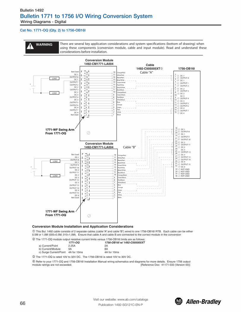
Bulletin 1492
Bulletin 1771 to 1756 I/O Wiring Conversion System
66Visit our website: www.ab.com/catalogs
Publication 1492-SG121C-EN-P
Wiring Diagrams - Digital
There are several key application considerations and system specifications (bottom of drawing) when using these components (conversion module, cable and input module). Read and understand these considerations before installation.
WARNING
Conversion Module1492-CM1771-LA004
Conversion Module1492-CM1771-LA004
1771-WF Swing ArmFrom 1771-OQ
1771-WF Swing ArmFrom 1771-OQ
Cable1492-C005005XT� 1756-OB16I
181716151413121110
987
432
6
1
5
Orange/Red
White/Red
Green/White
Blue/White
Orange/Black
Red/White
Black/Red
Blue/Black
Black/White
Green/Black
Blue
Orange
Red/Black
White/Black
18
14131211
8
65
171615
4321
109
7
Black
White
RedGreen
214
3
10
14
13
DC-1OUTPUT-0
OUTPUT 1
DC-2
OUTPUT 2
DC-2
6
8
12
5
9
7
11
15
OUTPUT 3
DC-3
DC-3
DC-4
16DC-4
DC-1
OUTPUT-4
OUTPUT 5OUTPUT 6
OUTPUT 7
LOAD
+
-
LOAD
181716151413121110
987
432
6
1
5
Orange/Red
White/Red
Green/White
Blue/White
Orange/Black
Red/White
Black/Red
Blue/Black
Black/White
Green/Black
Blue
Orange
Red/Black
White/Black
18
14131211
8
65
171615
4321
109
7
Black
White
RedGreen
181720
19
26
30
29
DC-1OUTPUT-8
OUTPUT 9
DC-2
OUTPUT 10
DC-2
22
24
28
21
25
23
27
31
OUTPUT 11
DC-3
DC-3
DC-4
32DC-4
DC-1
OUTPUT-12
OUTPUT 13OUTPUT 14
OUTPUT 15
LOAD
+
-
LOAD
NOT USED33343536
NOT USEDNOT USEDNOT USED
Cable “B”
Cable “A”DC-1
OUTPUT-0
OUTPUT 1
DC-2OUTPUT 2
DC-2OUTPUT 3
DC-3
DC-3
DC-4
DC-4
DC-1
OUTPUT-4
OUTPUT 5
OUTPUT 6
OUTPUT 7
Not Used
Not Used
DC-1OUTPUT-8
OUTPUT 9
DC-2OUTPUT 10
DC-2OUTPUT 11
DC-3
DC-3
DC-4
DC-4
DC-1
OUTPUT-12
OUTPUT 13
OUTPUT 14
OUTPUT 15
Not Used
Not Used
Conversion Module Installation and Application Considerations� This Bul. 1492 cable consists of 2 separate cables (cable “A” and cable “B”) wired to one 1756-OB16I RTB. Each cable can be either0.5M or 1.0M (005=0.5M, 010=1.0M). Ensure that cable A and cable B are connected to the correct module in the conversion
� The 1771-OQ module output resistive current limits versus 1756-OB16I limits are as follows: 1771-OQ 1756-OB16I w/ 1492-C005005XT a) Current/Point 2.25A 2A b) Current/Module 9A 8A c) Surge Current/Point 4A for 10ms 4A for 10ms
� The 1771-OQ is rated 10V to 32V DC. The 1756-OB16I is rated 10V to 30V DC.
� Refer to your 1771-OQ and 1756-OB16I Installation Manual wiring schematics and diagrams for more details. Ensure 1756 output module ratings are not exceeded. [Reference Doc: 41171-033 (Version 00)]
Cat No. 1771-OQ (Qty. 2) to 1756-OB16I

Bulletin 1492
Bulletin 1771 to 1756 I/O Wiring Conversion System
67Visit our website: www.ab.com/catalogs
Publication 1492-SG121C-EN-P
Wiring Diagrams- Digital
There are several key application considerations and system specifications (bottom of drawing) when using these components (conversion module, cable and input module). Read and understand these considerations before installation.
WARNING
� This Bul. 1492 cable consists of a cable wired to one 1756-OB16I RTB. Recommended cable lengths of 0.5M or 1.0M (005=0.5M, 010=1.0M). See table 2 for other lengths.
� The 1771-OQ16 module output current limits versus 1756-OB16I limits are as follows: 1771-OQ16 1756-OB16I w/ 1492-CONCAB005Ya) Current/Point 2A 2Ab) Current/Module 32A 8Ac) Surge Current/Point 4A for 10ms 4A for 10ms
� The 1771-OQ16 has sixteen (16) 3A, 250V rectifier fuses. The 1756-OB16I is NOT fused, as such sixteen(16) 2AG fuses and clips are provided on the 1492-CM1771-LD010F conversion module. Max fuse rating is 1.5A based on 1756-OA16I.
� The 1771-OQ16 is rated 10V to 32V DC. The 1756-OB16I is rated 10V to 30V DC.
� Refer to your 1771-OQ16 and 1756-OB16I Installation Manual wiring schematics and diagrams for more details. Ensure1756 output module ratings are not exceeded. [Reference Doc: 41171-010 (Version 00)]
Conversion Module Installation and Application Considerations
1771-WN Swing ArmFrom 1771-OQ16
12345678910111213
151617181920
14
21222324252627282930313233
353637
34
OUT-0
21
OUT-1
43
OUT-2
65
OUT-3
87
OUT-4
109
OUT-5
1211
OUT-6
1413
Orange
Blue
White/Black
Red/BlackGreen/Black
Orange/BlackBlue/Black
Black/White
Red/White
Green/White
Blue/White
Black/Red
White/Red
Orange/Red
Blue/Red
Red/GreenOUT-7
1615
OUT-8
1817
OUT-9
2019
OUT-10
2221
OUT-11
2423
OUT-12
2625
OUT-13
2827
OUT-14
3029
Orange/Green
Black/White/Red
White/Black/Red
Red/Black/WhiteGreen/Black/White
Orange/Black/WhiteBlue/Black/White
Black/Red/Green
White/Red/Green
Red/Black/Green
Green/Black/Orange
Orange/Black/Green
Blue/White/Orange
Black/White/Orange
White/Red/Orange
Orange/White/BlueOUT-15
3231
DC-0
DC-1
DC-2
DC-3
DC-4
DC-5
DC-6
DC-7
DC-8
DC-9
DC-10
DC-11
DC-12
DC-13
DC-14
DC-15
+
-
40
21Ouput 0
3Ouput 1
5Ouput 2
7Ouput 3
11Ouput 4
13Ouput 5
15Ouput 6
17Ouput 7
21Ouput 8
23Ouput 9
25Ouput 10
27Ouput 11
31Ouput 12
33Ouput 13
35Ouput 14
37Ouput 15
DC-0
DC-1
DC-2
DC-3
DC-4
DC-5
DC-6
DC-7
DC-8
DC-9
DC-10
DC-11
DC-12
DC-13
DC-14
DC-15
4
6
8
29
12
14
16
18
30
22
24
26
28
39
32
34
36
38
910
20
19
Not Used
Not UsedNot UsedNot Used
Not Used
Not UsedNot UsedNot Used
LOAD
Conversion Module1492-CM1771-LD010F
1756-OB16I Cable
1492-CONCAB005Y�
Cat No. 1771-OQ16 to 1756-OB16I

Bulletin 1492
Bulletin 1771 to 1756 I/O Wiring Conversion System
68Visit our website: www.ab.com/catalogs
Publication 1492-SG121C-EN-P
Wiring Diagrams - Digital
Conversion Module1492-CM1771-LD012
Conversion Module1492-CM1771-LD012
1771-WD Swing ArmFrom 1771-OR
1771-WD Swing ArmFrom 1771-OR
Cable1492-C005005XR� 1756-OA16I
There are several key application considerations and system specifications (bottom of drawing) when using these components (conversion module, cable and input module). Read and understand these considerations before installation.
WARNING
Conversion Module Installation and Application Considerations� This Bul. 1492 cable consists of 2 separate cables (cable “A” and cable “B”) wired to one 1756-OA16I RTB. Each cable can be either0.5M or 1.0M (005=0.5M, 010=1.0M). Ensure that cable A and cable B are connected to the correct module in the conversion
� The 1771-OR module output resistive current limits versus 1756-OA16I limits are as follows: 1771-OR 1756-OA16I w/ 1492-C005005XR a) Current/Point 2A 2A b) Current/Module 6A 5A @ 60°C c) Surge Current/Point 15A for 100ms 20A for 43ms
� The 1771-OR module had a jumper selection of N.O. and N.C. outputs. The 1756-OA16I has both N.O. and N.C. outputs, but selection is by wiring termination on the 1756 swing arm. The 1492-CM1771-LD012 conversion module replaces the functionalityof the 1771-OR jumpers with eight jumpers (JMP0 through JMP7). In the default position, the output will be N.O. If a N.C. output isrequired, change the jumper from pins 1-2 to pins 3-4.
� Refer to your 1771-OR and 1756-OA16I Installation Manual wiring schematics and diagrams for more details. Ensure 1756 output module ratings are not exceeded. [Reference Doc: 41171-017 (Version 00)]
2
1
5
468
9
11
293031
NOT USEDNOT USED
L2-0
L1-0L1-1L1-2
L2-2L2-1
L1-3
L2-3
L1-4
CABLE ”A”
NOT USED
12345
678910111213
151617181920
14
21222324252627282930313233
353637
34
1492-CONCAB005Y
Orange
Blue
White/Black
Red/BlackGreen/Black
Orange/BlackBlue/Black
Black/White
Red/White
Green/White
Blue/White
Black/Red
White/Red
Orange/Red
Blue/Red
Red/Green
Orange/Green
Black/White/Red
White/Black/Red
Red/Black/WhiteGreen/Black/White
Orange/Black/WhiteBlue/Black/White
Black/Red/Green
White/Red/Green
Red/Black/Green
Green/Black/Orange
Orange/Black/Green
Blue/White/Orange
Black/White/Orange
White/Red/Orange
Orange/White/Blue
1
56789101112
0-OUT
0-IN234
1-IN
2-IN
1-OUT
2-OUT
3-OUT
3-IN
4-IN
5-IN4-OUT
5-OUT
1
3
2
4
N.O.
N.C.
1
3
2
4
N.O.
N.C.
JMP0
JMP1
1
3
2
4
N.O.
N.C.
JMP2
1
3
2
4
N.O.
N.C.
1
3
2
4
N.O.
N.C.
JMP3
JMP4
1
3
2
4
N.O.
N.C.
JMP5
1
3
2
4
N.O.
N.C.
JMP6
1
3
2
4
N.O.
N.C.
JMP7
L1-5
L2-4L2-5
12345
678910111213
151617181920
14
21222324252627282930313233
353637
34
LOAD
Orange
Blue
White/Black
Red/BlackGreen/Black
Orange/BlackBlue/Black
Black/White
Red/White
Green/White
Blue/White
Black/Red
White/Red
Orange/Red
Blue/Red
Red/Green
Orange/Green
Black/White/Red
White/Black/Red
Red/Black/WhiteGreen/Black/White
Orange/Black/WhiteBlue/Black/White
Black/Red/Green
White/Red/Green
Red/Black/Green
Green/Black/Orange
Orange/Black/Green
Blue/White/Orange
Black/White/Orange
White/Red/Orange
Orange/White/Blue
1
56789101112
234
1
3
2
4
N.O.
N.C.
1
3
2
4
N.O.
N.C.
JMP0
JMP1
1
3
2
4
N.O.
N.C.
JMP2
1
3
2
4
N.O.
N.C.
1
3
2
4
N.O.
N.C.
JMP3
JMP4
1
3
2
4
N.O.
N.C.
JMP5
1
3
2
4
N.O.
N.C.
JMP6
1
3
2
4
N.O.
N.C.
JMP7
3
13
CABLE ”B”
L1L2
LOAD
L1L2
10
12
6-OUT
6-IN
7-IN
8-IN
7-OUT
8-OUT
9-OUT
9-IN
10-IN
11-IN10-OUT
11-OUT
14
15
19
161820
21
23
L2-6
L1-6L1-7L1-8
L2-8L2-7
L1-9
L2-9
L1-10
L1-11
L2-10L2-11
17
25
22
24
262728
NOT USEDNOT USED
NOT USED
343536
NOT USEDNOT USED
NOT USED
3233
NOT USEDNOT USED
Cat No. 1771-OR (Qty. 2) to 1756-OA16I

Bulletin 1492
Bulletin 1771 to 1756 I/O Wiring Conversion System
69Visit our website: www.ab.com/catalogs
Publication 1492-SG121C-EN-P
Wiring Diagrams- Digital
There are several key application considerations and system specifications (bottom of drawing) when using these components (conversion module, cable and input module). Read and understand these considerations before installation.
WARNING
10L1-0L2-0
1OUT-0
2OUT-1
3OUT-2
4
OUT-12
5
OUT-13
6
OUT-14
7
OUT-15
81112131415161718
Black
WhiteRed
Green
Orange
Blue
White/Black
Red/BlackGreen/Black
Orange/BlackBlue/Black
Black/White
Red/White
Green/White
Blue/White
Black/Red
White/Red
12345
78910
18
111213
151617
14
L1-119
9
OUT-3
20
L2-1
OUT-4OUT-5OUT-6OUT-7OUT-8OUT-9OUT-10OUT-11
1771-WN Swing ArmFrom 1771-OVN
10
123456781112131415161718
19
9
20
20 Red/Green
21 Orange/Green
22 Black/White/Red
24 Red/Black/White
25 Green/Black/White
26 Orange/Black/White27 Blue/Black/White28 Black/Red/Green29 White/Red/Green
30 Red/Black/Green
31 Green/Black/Orange
32 Orange/Black/Green33 Blue/White/Orange
34 Black/White/Orange
35 White/Red/Orange
36White/Red/Blue37
A EL
UD
OM
B EL
UD
OM
30
202
40
43
65
87
129
34
13
1
1615
1817
22
19
2423
2625
2827
3229
11
33
10L2L2
L2L2
Output 00Output 01Output 02Output 03Output 04Output 05Output 06Output 07Output 10Output 11
Output 13
Output 15
Output 12
Output 17
L1
35
31
14
L1
21L1
Output 14
Output 16
38
3637
39
L1
Output 00Output 01Output 02Output 03
Output 04Output 05Output 06Output 07Output 10Output 11
Output 13
Output 15
Output 12
Output 17
Output 14
Output 16
Orange/Red
6
L1-0L2-0OUT-0OUT-1OUT-2
OUT-12OUT-13OUT-14OUT-15L1-1
OUT-3
L2-1
OUT-4OUT-5OUT-6OUT-7OUT-8OUT-9OUT-10OUT-11
23 White/Black/Red
Orange/White/Blue
L1
L2
OutputDevice
19 Blue/Red
1756-OV16E
1756-OV16E
Conversion Module1492-CM1771-LD013
Cable1492-CONCAB005S3�
�
�
�
�
Conversion Module Installation and Application Considerations� This Bul. 1492 cable consists of a cable wired to two 1756-OV16E RTB. Recommended cable lengths of 0.5M or 1.0M (005=0.5M, 010=1.0M). See table 2 for other lengths.
� The 1771-OVN module output current limits versus 1756-OV16E limits are as follows: 1771-OVN 1756-OV16E w/ 1492-CONCAB005S3a) Current/Point 0.5A 1Ab) Current/Module 8A (32 pts) 8A (16 pts)c) Surge Current/Point 2A for 10ms 2A for 10ms
� The 1771-OVN has 4 groups (allowing 4 separate power supplies). This module/cable combination ties all 4 groups from the 1771-OVN together. Field wiring modification must be made to accommodate this if mulitple supplies were used. If more than 1 supply was used, all but 1 of the power supplies must be removed.
� The 1771-OVN did not allow connections for L2, however the 1756-OV16E requires an L2 connection for proper operation. The 1771-OVN did not use terminals 10, 20, 30, 40. These terminals have been reassigned for an L2 connection in this application. The installer must rewire L2 to one of these terminals.
� Refer to your 1771-OVN and 1756-OV16E Installation Manual wiring schematics and diagrams for more details. Ensure 1756 output module ratings are not exceeded.
� This configuration uses two (2) 1756-OV16E output modules to replace a single 1771-OVN output module. This may require the use of a larger 1756 I/O chassis and conversion mounting assembly. Ensure there is sufficient panel space to allow for this possibility.
[Reference Doc: 41171-018 (Version 00)]
Cat No. 1771-OVN to 1756-OV16E (Qty. 2)

Bulletin 1492
Bulletin 1771 to 1756 I/O Wiring Conversion System
70Visit our website: www.ab.com/catalogs
Publication 1492-SG121C-EN-P
Wiring Diagrams - Digital
There are several key application considerations and system specifications (bottom of drawing) when using these components (conversion module, cable and input module). Read and understand these considerations before installation.
WARNING
Conversion Module1492-CM1771-LD012
1771-WD Swing ArmFrom 1771-OW
Cable1492-CONCAB005Y�
Conversion Module Installation and Application Considerations� This Bul. 1492 cable consists of a cable wired to one 1756-OX8I RTB. Recommended cable lengths of 0.5M or 1.0M (005=0.5M), 010=1.0M). See table 2 for other lengths.
� The 1771-OW module output resistive current limits versus 1756-OX8I limits are as follows:(NOTE: For switching and inductive current ratings, refer to the modules Installation Instructions) 1771-OW 1756-OX8I w/ 1492-CONCAB005Y a) Current/Point 0.2A @ 138V AC 2A @ 240V AC 1A @ 30V DC 2A @ 30V DC 0.25A @ 125V DC 0.25A @ 125V DC
� The 1771-OW module had a jumper selection of N.O. and N.C. outputs. The 1756-OX8I has both N.O. and N.C. outputs, but selection is by wiring termination on the 1756 swing arm. The 1492-CM1771-LD012 conversion module replaces the functionalityof the 1771-OW jumpers with eight jumpers (JMP0 through JMP7). In the default position, the output will be N.O. If a N.C. output isrequired, change the jumper from pins 1-2 to pins 3-4.
� Refer to your 1771-OW and 1756-OX8I Installation Manual wiring schematics and diagrams for more details. Ensure 1756 output module ratings are not exceeded. [Reference Doc: 41170-941 (Version 01)]
4 3
2 1
N.C.
N.O.
4 3
2 1
N.C.
N.O.
4 3
2 1
N.C.
N.O.
4 3
2 1
N.C.
N.O.
4 3
2 1
N.C.
N.O.
4 3
2 1
N.C.
N.O.
L1-0OUT-0 N.C.L1-0
OUT-0 N.O.L1-1OUT-1 N.C.L1-1OUT-1 N.O.L1-2OUT-2 N.C.L1-2OUT-2 N.O.L1-3OUT-3 N.C.L1-3OUT-3 N.O.L1-4OUT-4 N.C.
L1-4OUT-4 N.O.L1-5OUT-5 N.C.L1-5OUT-5 N.O.L1-6OUT-6 N.C.
L1-6OUT-6 N.O.L1-7OUT-7 N.C.L1-7
OUT-7 N.O.
12
345678910
1112131415161718
192021222324
25262728293031323334353637
Orange
Blue
White/Black
Red/Black
Green/Black
Orange/Black
Blue/Black
Black/White
Red/White
Green/White
Blue/White
Black/Red
White/Red
Orange/Red
Blue/Red
Red/Green
Orange/Green
Black/White/Red
White/Black/Red
Red/Black/White
Green/Black/White
Orange/Black/White
Blue/Black/White
Black/Red/Green
White/Red/Green
Red/Black/Green
Green/Black/Orange
Orange/Black/Green
Blue/White/Orange
Black/White/Orange
White/Red/Orange
Orange/White/Blue
4 3
2 1
N.C.
N.O.
JMP74 3
2 1
N.C.
N.O.
JMP6
JMP5
JMP4
JMP3
JMP2
JMP1
JMP0
1234
56
789
101112
LOAD
L1
L2
LOAD
+
-
Out-0 N.O./N.C.+V0/1
Out-1 N.O./N.C.Out-2 N.O./N.C.
+V2/3Out-3 N.O./N.C.Out-4 N.O./N.C.
+V4/5Out-5 N.O./N.C.
Out-6 N.O./N.C.+V6/7
Out-7 N.O./N.C.
2143658710912111413161518172019222124232625282730293231
1756-OX8I
Cat No. 1771-OW to 1756-OX8I

Bulletin 1492
Bulletin 1771 to 1756 I/O Wiring Conversion System
71Visit our website: www.ab.com/catalogs
Publication 1492-SG121C-EN-P
Wiring Diagrams- Digital
Conversion Module Installation and Application Considerations� The 1771-OW16 module output resistive current limits versus 1756-OW16I limits are as follows: 1771-OW16 1756-OW16I w/ 1492-CONCAB005Ya) Current/Point 2A @ 250V AC 2A @ 240V AC 2A @ 30V DC 2A @ 30V DC 0.3A @ 150V DC 0.25A @ 125V AC� The 1492-CONCAB005Y is limited to 3A per pin.� The 1771-OW16 has N.O. and N.C. relay contact outputs. The 1756-OW16I has N.O. relay contact outputs only. The conver-sion module does not convert the N.C. to N.O. contacts. If the 1771-OW16 N.C. outputs were being used, the installer must rewire the 1771-WN swing arm and move the N.C. wires to the N.O. output terminals. In addition, the control Logix programming will need to be changed to simulate a N.C. relay with this output.� Refer to your 1771-OW16 and 1756-OW16I Installation Manual wiring schematics and diagrams for more details. Ensure 1756 output module ratings are not exceeded. Reference Doc: 41170-940 (Version 01)]
There are several key application considerations and system specifications (bottom of drawing) when using these components (conversion module, cable and input module). Read and understand these considerations before installation.
WARNING
1 2
17202326
4
365
8
71091211141316151918
2221252428
273130
3433
37364039
29323538
Output 14 (NO)
Output 16 (NO)
Output 15 (NO)
Output 04
Output 06
Output 05
Output 07
Output 00
Output 02
Output 01
Output 03
Output 10 (NO)
Output 12 (NO)
Output 11(NO)
Output 13 (NO)
Output 17 (NO)Output 14 (NC)Output 15 (NC)Output 16 (NC)Output 17 (NC)
12345678910111213
151617181920
14
21222324252627282930313233
353637
34
OUT-0 N.O.
21
OUT-1 N.O.
43
OUT-2 N.O.
65
OUT-3 N.O.
87
OUT-4 N.O.
109
OUT-5 N.O.
1211
OUT-6 N.O.
1413
Orange
Blue
White/Black
Red/BlackGreen/Black
Orange/BlackBlue/Black
Black/White
Red/White
Green/White
Blue/White
Black/Red
White/Red
Orange/Red
Blue/Red
Red/GreenOUT-7 N.O.
1615
OUT-8 N.O.
1817
OUT-9 N.O.
2019
OUT-10 N.O.
2221
OUT-11 N.O.
2423
OUT-12 N.O.
2625
OUT-13 N.O.
2827
OUT-14 N.O.
3029
Orange/Green
Black/White/Red
White/Black/Red
Red/Black/WhiteGreen/Black/White
Orange/Black/WhiteBlue/Black/White
Black/Red/Green
White/Red/Green
Red/Black/Green
Green/Black/Orange
Orange/Black/Green
Blue/White/Orange
Black/White/Orange
White/Red/Orange
Orange/White/BlueOUT-15 N.O.
3231
L1-0
L1-1
L1-2
L1-3
L1-4
L1-5
L1-6
L1-7
L1-8
L1-9
L1-10
L1-11
L1-12
L1-13
L1-14
L1-15
L1
L2
Common 00
Common 01
Common 02
Common 03
Common 04
Common 05
Common 06
Common 07
Common 10
Common 11
Common 12
Common 13
Common 14
Common 15
Common 16
Common 17
Output 10 (NC)Output 11 (NC)Output 12 (NC)Output 13 (NC)
+
- LOAD
LOAD
Conversion Module1492-CM1771-LD011
Cable1492-CONCAB005Y� 1756-OW16I
1771-WN Swing ArmFrom 1771-OW16
Cat No. 1771-OW16 to 1756-OW16I

Bulletin 1492
Bulletin 1771 to 1756 I/O Wiring Conversion System
72Visit our website: www.ab.com/catalogs
Publication 1492-SG121C-EN-P
Wiring Diagrams - Digital
There are several key application considerations and system specifications (bottom of drawing) when using these components (conversion module, cable and input module). Read and understand these considerations before installation.
WARNING
1771-WN Swing ArmFrom 1771-OWNA
2L1-0L2-0
1OUT-0
3OUT-1
5OUT-2
7
OUT-12
9
OUT-13
11
OUT-14
13
OUT-15
151719212325272931
Black
WhiteRed
Green
Orange
Blue
White/Black
Red/BlackGreen/Black
Orange/BlackBlue/Black
Black/White
Red/White
Green/White
Blue/White
Black/Red
White/Red
12345
78910
18
111213
151617
14
L1-1
OUT-3
4
L1-1
OUT-4OUT-5OUT-6OUT-7OUT-8OUT-9OUT-10OUT-11
20 Red/Green
21 Orange/Green
22 Black/White/Red
24 Red/Black/White
25 Green/Black/White
26 Orange/Black/White27 Blue/Black/White28 Black/Red/Green29 White/Red/Green
30 Red/Black/Green
31 Green/Black/Orange
32 Orange/Black/Green33 Blue/White/Orange
34 Black/White/Orange
35 White/Red/Orange
36White/Red/Blue37
AB
ELU
DO
MEL
UD
OM
30
202
40
43
65
87
129
34
13
1
1615
1817
22
19
2423
2625
2827
3229
11
33
10L2L2
L2L2
Output 00Output 01Output 02Output 03Output 04Output 05Output 06Output 07Output 10Output 11
Output 13
Output 15
Output 12
Output 17
L1
35
31
14
L1
21L1
Output 14
Output 16
38
3637
39
L1
Output 00Output 01Output 02Output 03
Output 04Output 05Output 06Output 07Output 10Output 11
Output 13
Output 15
Output 12
Output 17
Output 14
Output 16
Orange/Red
6
23 White/Black/Red
Orange/White/Blue
L1
L2
OutputDevice
19 Blue/Red
L1-1
L1-1
6
3234
2L1-0L2-0
1OUT-0
3OUT-1
5OUT-2
7
OUT-12
9
OUT-13
11
OUT-14
13
OUT-15
151719212325272931
L1-1
OUT-3
4
L1-1
OUT-4OUT-5OUT-6OUT-7OUT-8OUT-9OUT-10OUT-11
L1-1
L1-1
6
3234
1756-OW16I
1756-OW16I
Conversion Module1492-CM1771-LD013
Cable1492-CONCAB005S4�
�
��
�
�
Conversion Module Installation and Application Considerations� This Bul. 1492 cable consists of a cable wired to two 1756-OW16I RTB. Recommended cable lengths of 0.5M or 1.0M (005=0.5M, 010=1.0M). See table 2 for other lengths.
� The 1771-OWNA module output current limits versus 1756-OW16I limits are as follows: 1771-OWNA 1756-OW16I w/ 1492-CONCAB005S4a) Current/Point 1A 0.5Ab) Current/Module 12A (32 pts) 2A (16 pts)
� The 1771-OWNA has 4 groups (allowing 4 separate power supplies). This module/cable combination ties all 4 groups from the 1771-OWNA together. Field wiring modification must be made to accommodate this if mulitple supplies were used. If more than 1 supply was used, all but 1 of the power supplies must be removed.
� The 1771-OWNA did not allow connections for L2, however the 1756-OW16I requires an L2 connection for proper operation. The 1771-OWNA did not use terminals 10, 20, 30, 40. These terminals have been reassigned for an L2 connection in this application. The installer must rewire L2 to one of these terminals.
� Refer to your 1771-OWNA and 1756-OW16I Installation Manual wiring schematics and diagrams for more details. Ensure 1756 output module ratings are not exceeded.
� This configuration uses two (2) 1756-OW16I output modules to replace a single 1771-OWNA output module. This may require the use of a larger 1756 I/O chassis and conversion mounting assembly. Ensure there is sufficient panel space to allow for this possibility.
� 1756-OW16I output modules has all inputs jumpered together pins 2 through 34 even. [Reference Doc: 41171-019 (Version 00)]
Cat No. 1771-OWNA to 1756-OW16I (Qty. 2)

Bulletin 1492
Bulletin 1771 to 1756 I/O Wiring Conversion System
73Visit our website: www.ab.com/catalogs
Publication 1492-SG121C-EN-P
Wiring Diagrams- Digital
There are several key application considerations and system specifications (bottom of drawing) when using these components (conversion module, cable and input module). Read and understand these considerations before installation.
WARNING
Conversion Module1492-CM1771-LD012
1771-WD Swing ArmFrom 1771-OY
Cable1492-CONCAB005Y� 1756-OX8I
Conversion Module Installation and Application Considerations� This Bul. 1492 cable consists of a cable wired to one 1756-OX8I RTB. Recommended cable lengths of 0.5M or 1.0M (005=0.5M), 010=1.0M). See table 2 for other lengths.
� The 1771-OY module output resistive current limits versus 1756-OX8I limits are as follows:(NOTE: For switching and inductive current ratings, refer to the modules Installation Instructions) 1771-OY 1756-OX8I w/ 1492-CONCAB005Y a) Current/Point 100mA @ 138V AC 2A @ 240V AC 100mA @ 125V DC 2A @ 30V DC 0.25A @ 125V DC
� The 1771-OY module had a jumper selection of N.O. and N.C. outputs. The 1756-OX8I has both N.O. and N.C. outputs, but selection is by wiring termination on the 1756 swing arm. The 1492-CM1771-LD012 conversion module replaces the functionalityof the 1771-OY jumpers with eight jumpers (JMP0 through JMP7). In the default position, the output will be N.O. If a N.C. output isrequired, change the jumper from pins 1-2 to pins 3-4.
� Refer to your 1771-OY and 1756-OX8I Installation Manual wiring schematics and diagrams for more details. Ensure 1756 output module ratings are not exceeded. [Reference Doc: 41171-011 (Version 00)]
12345
678910111213
151617181920
14
21222324252627282930313233
353637
34
LOAD
OUT-0 N.C.
21
OUT-0 N.O.
43
OUT-1 N.C.
65
OUT-1 N.O.
87
OUT-2 N.C.
109
OUT-2 N.O.
1211
OUT-3 N.C.
1413
Orange
Blue
White/Black
Red/BlackGreen/Black
Orange/BlackBlue/Black
Black/White
Red/White
Green/White
Blue/White
Black/Red
White/Red
Orange/Red
Blue/Red
Red/GreenOUT-3 N.O.
1615
OUT-4 N.C.
1817
OUT-4 N.O.
2019
OUT-5 N.C.
2221
OUT-5 N.O.
2423
OUT-6 N.C.
2625
OUT-6 N.O.
2827
OUT-7 N.C.
3029
Orange/Green
Black/White/Red
White/Black/Red
Red/Black/WhiteGreen/Black/White
Orange/Black/WhiteBlue/Black/White
Black/Red/Green
White/Red/Green
Red/Black/Green
Green/Black/Orange
Orange/Black/Green
Blue/White/Orange
Black/White/Orange
White/Red/Orange
Orange/White/BlueOUT-7 N.O.
3231
L1-0
L1-0
L1-1
L1-1
L1-2
L1-2
L1-3
L1-3
L1-4
L1-4
L1-5
L1-5
L1-6
L1-6
L1-7
L1-7
L1
L2
+
- LOAD
1
56789101112
+V0/1
Out-0 N.O./N.C.
234
Out-1 N.O./N.C.
+V2/3
Out-2 N.O./N.C.
Out-3 N.O./N.C.
+V4/5
Out-4 N.O./N.C.
Out-5 N.O./N.C.
+V6/7
Out-6 N.O./N.C.
Out-7 N.O./N.C.
1
3
2
4
N.O.
N.C.
1
3
2
4
N.O.
N.C.
JMP0
JMP1
1
3
2
4
N.O.
N.C.
JMP2
1
3
2
4
N.O.
N.C.
1
3
2
4
N.O.
N.C.
JMP3
JMP4
1
3
2
4
N.O.
N.C.
JMP5
1
3
2
4
N.O.
N.C.
JMP6
1
3
2
4
N.O.
N.C.
JMP7
Cat No. 1771-OY to 1756-OX8I

Bulletin 1492
Bulletin 1771 to 1756 I/O Wiring Conversion System
74Visit our website: www.ab.com/catalogs
Publication 1492-SG121C-EN-P
Wiring Diagrams - Digital
There are several key application considerations and system specifications (bottom of drawing) when using these components (conversion module, cable and input module). Read and understand these considerations before installation.
WARNING
1771-WD Swing ArmFrom 1771-OYL
Cable1492-CONCAB005Y� 1756-OX8I
Conversion Module Installation and Application Considerations� This Bul. 1492 cable consists of a cable wired to one 1756-OX8I RTB. Recommended cable lengths of 0.5M or 1.0M (005=0.5M), 010=1.0M). See table 2 for other lengths.
� The 1771-OYL module output resistive current limits versus 1756-OX8I limits are as follows:(NOTE: For switching and inductive current ratings, refer to the modules Installation Instructions) 1771-OYL 1756-OX8I w/ 1492-CONCAB005Y a) Current/Point 100mA @ 24V AC 2A @ 240V AC 100mA @ 24V DC 2A @ 30V DC 0.25A @ 125V DC
� The 1771-OYL module had a jumper selection of N.O. and N.C. outputs. The 1756-OX8I has both N.O. and N.C. outputs, but selection is by wiring termination on the 1756 swing arm. The 1492-CM1771-LD012 conversion module replaces the functionalityof the 1771-OYL jumpers with eight jumpers (JMP0 through JMP7). In the default position, the output will be N.O. If a N.C. output isrequired, change the jumper from pins 1-2 to pins 3-4.
� Refer to your 1771-OYL and 1756-OX8I Installation Manual wiring schematics and diagrams for more details. Ensure 1756 output module ratings are not exceeded. [Reference Doc: 41171-012 (Version 00)]
Conversion Module1492-CM1771-LD012
12345
678910111213
151617181920
14
21222324252627282930313233
353637
34
LOAD
OUT-0 N.C.
21
OUT-0 N.O.
43
OUT-1 N.C.
65
OUT-1 N.O.
87
OUT-2 N.C.
109
OUT-2 N.O.
1211
OUT-3 N.C.
1413
Orange
Blue
White/Black
Red/BlackGreen/Black
Orange/BlackBlue/Black
Black/White
Red/White
Green/White
Blue/White
Black/Red
White/Red
Orange/Red
Blue/Red
Red/GreenOUT-3 N.O.
1615
OUT-4 N.C.
1817
OUT-4 N.O.
2019
OUT-5 N.C.
2221
OUT-5 N.O.
2423
OUT-6 N.C.
2625
OUT-6 N.O.
2827
OUT-7 N.C.
3029
Orange/Green
Black/White/Red
White/Black/Red
Red/Black/WhiteGreen/Black/White
Orange/Black/WhiteBlue/Black/White
Black/Red/Green
White/Red/Green
Red/Black/Green
Green/Black/Orange
Orange/Black/Green
Blue/White/Orange
Black/White/Orange
White/Red/Orange
Orange/White/BlueOUT-7 N.O.
3231
L1-0
L1-0
L1-1
L1-1
L1-2
L1-2
L1-3
L1-3
L1-4
L1-4
L1-5
L1-5
L1-6
L1-6
L1-7
L1-7
L1
L2
+
- LOAD
1
56789101112
+V0/1
Out-0 N.O./N.C.
234
Out-1 N.O./N.C.
+V2/3
Out-2 N.O./N.C.
Out-3 N.O./N.C.
+V4/5
Out-4 N.O./N.C.
Out-5 N.O./N.C.
+V6/7
Out-6 N.O./N.C.
Out-7 N.O./N.C.
1
3
2
4
N.O.
N.C.
1
3
2
4
N.O.
N.C.
JMP0
JMP1
1
3
2
4
N.O.
N.C.
JMP2
1
3
2
4
N.O.
N.C.
1
3
2
4
N.O.
N.C.
JMP3
JMP4
1
3
2
4
N.O.
N.C.
JMP5
1
3
2
4
N.O.
N.C.
JMP6
1
3
2
4
N.O.
N.C.
JMP7
Cat No. 1771-OYL to 1756-OX8I

Bulletin 1492
Bulletin 1771 to 1756 I/O Wiring Conversion System
75Visit our website: www.ab.com/catalogs
Publication 1492-SG121C-EN-P
Wiring Diagrams- Digital
There are several key application considerations and system specifications (bottom of drawing) when using these components (conversion module, cable and input module). Read and understand these considerations before installation.
WARNING
1771-WD Swing ArmFrom 1771-OZ
Conversion Module Installation and Application Considerations� This Bul. 1492 cable consists of a cable wired to one 1756-OX8I RTB. Recommended cable lengths of 0.5M or 1.0M (005=0.5M), 010=1.0M). See table 2 for other lengths.
� The 1771-OZ module output resistive current limits versus 1756-OX8I limits are as follows:(NOTE: For switching and inductive current ratings, refer to the modules Installation Instructions) 1771-OZ 1756-OX8I w/ 1492-CONCAB005Y a) Current/Point 100mA @ 138V AC 2A @ 240V AC 100mA @ 138V DC 2A @ 30V DC 0.25A @ 125V DC
� The 1771-OZ module had a jumper selection of N.O. and N.C. outputs. The 1756-OX8I has both N.O. and N.C. outputs, but selection is by wiring termination on the 1756 swing arm. The 1492-CM1771-LD012 conversion module replaces the functionalityof the 1771-OZ jumpers with eight jumpers (JMP0 through JMP7). In the default position, the output will be N.O. If a N.C. output isrequired, change the jumper from pins 1-2 to pins 3-4.
� Refer to your 1771-OZ and 1756-OX8I Installation Manual wiring schematics and diagrams for more details. Ensure 1756 output module ratings are not exceeded. [Reference Doc: 41171-013 (Version 00)]
Cable1492-CONCAB005Y� 1756-OX8I
Conversion Module1492-CM1771-LD012
12345
678910111213
151617181920
14
21222324252627282930313233
353637
34
LOAD
OUT-0 N.C.
21
OUT-0 N.O.
43
OUT-1 N.C.
65
OUT-1 N.O.
87
OUT-2 N.C.
109
OUT-2 N.O.
1211
OUT-3 N.C.
1413
Orange
Blue
White/Black
Red/BlackGreen/Black
Orange/BlackBlue/Black
Black/White
Red/White
Green/White
Blue/White
Black/Red
White/Red
Orange/Red
Blue/Red
Red/GreenOUT-3 N.O.
1615
OUT-4 N.C.
1817
OUT-4 N.O.
2019
OUT-5 N.C.
2221
OUT-5 N.O.
2423
OUT-6 N.C.
2625
OUT-6 N.O.
2827
OUT-7 N.C.
3029
Orange/Green
Black/White/Red
White/Black/Red
Red/Black/WhiteGreen/Black/White
Orange/Black/WhiteBlue/Black/White
Black/Red/Green
White/Red/Green
Red/Black/Green
Green/Black/Orange
Orange/Black/Green
Blue/White/Orange
Black/White/Orange
White/Red/Orange
Orange/White/BlueOUT-7 N.O.
3231
L1-0
L1-0
L1-1
L1-1
L1-2
L1-2
L1-3
L1-3
L1-4
L1-4
L1-5
L1-5
L1-6
L1-6
L1-7
L1-7
L1
L2
+
- LOAD
1
56789101112
+V0/1
Out-0 N.O./N.C.
234
Out-1 N.O./N.C.
+V2/3
Out-2 N.O./N.C.
Out-3 N.O./N.C.
+V4/5
Out-4 N.O./N.C.
Out-5 N.O./N.C.
+V6/7
Out-6 N.O./N.C.
Out-7 N.O./N.C.
1
3
2
4
N.O.
N.C.
1
3
2
4
N.O.
N.C.
JMP0
JMP1
1
3
2
4
N.O.
N.C.
JMP2
1
3
2
4
N.O.
N.C.
1
3
2
4
N.O.
N.C.
JMP3
JMP4
1
3
2
4
N.O.
N.C.
JMP5
1
3
2
4
N.O.
N.C.
JMP6
1
3
2
4
N.O.
N.C.
JMP7
Cat No. 1771-OZ to 1756-OX8I

Bulletin 1492
Bulletin 1771 to 1756 I/O Wiring Conversion System
76Visit our website: www.ab.com/catalogs
Publication 1492-SG121C-EN-P
Wiring Diagrams - Digital
There are several key application considerations and system specifications (bottom of drawing) when using these components (conversion module, cable and input module). Read and understand these considerations before installation.
WARNING
1771-WD Swing ArmFrom 1771-OZL
Conversion Module Installation and Application Considerations� This Bul. 1492 cable consists of a cable wired to one 1756-OX8I RTB. Recommended cable lengths of 0.5M or 1.0M (005=0.5M), 010=1.0M). See table 2 for other lengths.
� The 1771-OZL module output resistive current limits versus 1756-OX8I limits are as follows:(NOTE: For switching and inductive current ratings, refer to the modules Installation Instructions) 1771-OZL 1756-OX8I w/ 1492-CONCAB005Y a) Current/Point 100mA @ 138V AC 2A @ 240V AC 100mA @ 138V DC 2A @ 30V DC 0.25A @ 125V DC
� The 1771-OZL module had a jumper selection of N.O. and N.C. outputs. The 1756-OX8I has both N.O. and N.C. outputs, but selection is by wiring termination on the 1756 swing arm. The 1492-CM1771-LD012 conversion module replaces the functionalityof the 1771-OZL jumpers with eight jumpers (JMP0 through JMP7). In the default position, the output will be N.O. If a N.C. output isrequired, change the jumper from pins 1-2 to pins 3-4.
� Refer to your 1771-OZL and 1756-OX8I Installation Manual wiring schematics and diagrams for more details. Ensure 1756 output module ratings are not exceeded. [Reference Doc: 41171-014 (Version 00)]
Cable1492-CONCAB005Y� 1756-OX8I
Conversion Module1492-CM1771-LD012
12345
678910111213
151617181920
14
21222324252627282930313233
353637
34
LOAD
OUT-0 N.C.
21
OUT-0 N.O.
43
OUT-1 N.C.
65
OUT-1 N.O.
87
OUT-2 N.C.
109
OUT-2 N.O.
1211
OUT-3 N.C.
1413
Orange
Blue
White/Black
Red/BlackGreen/Black
Orange/BlackBlue/Black
Black/White
Red/White
Green/White
Blue/White
Black/Red
White/Red
Orange/Red
Blue/Red
Red/GreenOUT-3 N.O.
1615
OUT-4 N.C.
1817
OUT-4 N.O.
2019
OUT-5 N.C.
2221
OUT-5 N.O.
2423
OUT-6 N.C.
2625
OUT-6 N.O.
2827
OUT-7 N.C.
3029
Orange/Green
Black/White/Red
White/Black/Red
Red/Black/WhiteGreen/Black/White
Orange/Black/WhiteBlue/Black/White
Black/Red/Green
White/Red/Green
Red/Black/Green
Green/Black/Orange
Orange/Black/Green
Blue/White/Orange
Black/White/Orange
White/Red/Orange
Orange/White/BlueOUT-7 N.O.
3231
L1-0
L1-0
L1-1
L1-1
L1-2
L1-2
L1-3
L1-3
L1-4
L1-4
L1-5
L1-5
L1-6
L1-6
L1-7
L1-7
L1
L2
+
- LOAD
1
56789101112
+V0/1
Out-0 N.O./N.C.
234
Out-1 N.O./N.C.
+V2/3
Out-2 N.O./N.C.
Out-3 N.O./N.C.
+V4/5
Out-4 N.O./N.C.
Out-5 N.O./N.C.
+V6/7
Out-6 N.O./N.C.
Out-7 N.O./N.C.
1
3
2
4
N.O.
N.C.
1
3
2
4
N.O.
N.C.
JMP0
JMP1
1
3
2
4
N.O.
N.C.
JMP2
1
3
2
4
N.O.
N.C.
1
3
2
4
N.O.
N.C.
JMP3
JMP4
1
3
2
4
N.O.
N.C.
JMP5
1
3
2
4
N.O.
N.C.
JMP6
1
3
2
4
N.O.
N.C.
JMP7
Cat No. 1771-OZL to 1756-OX8I
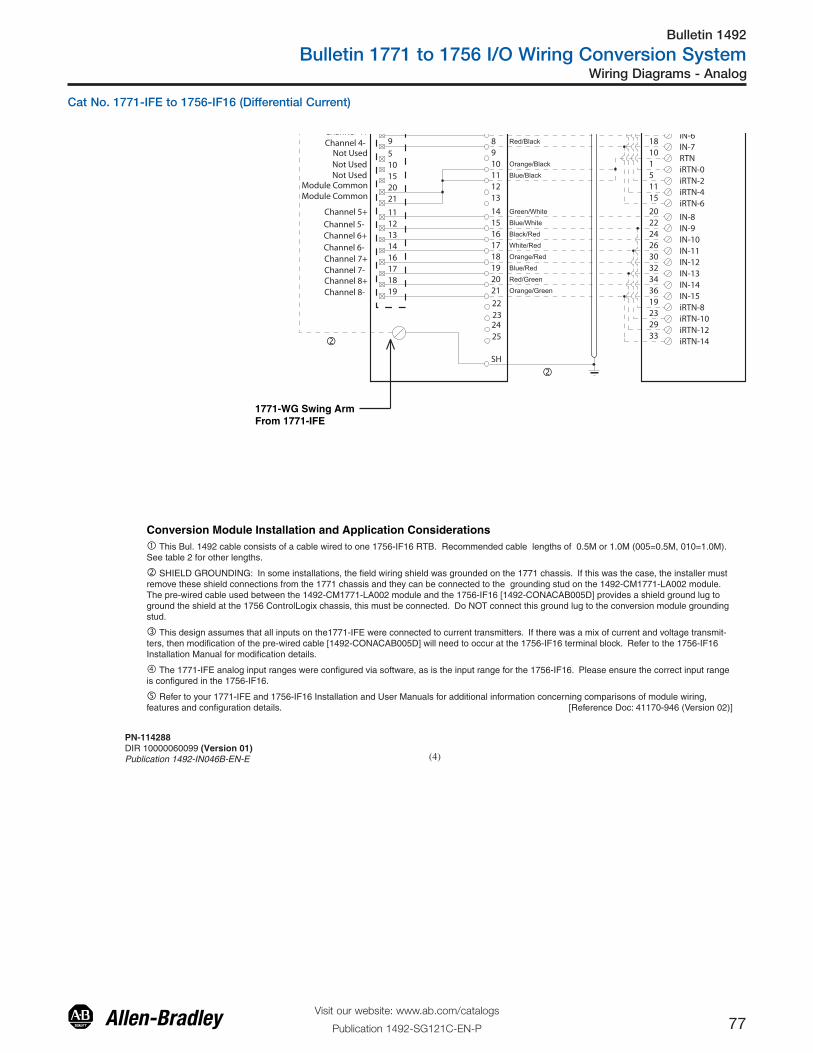
Bulletin 1492
Bulletin 1771 to 1756 I/O Wiring Conversion System
77Visit our website: www.ab.com/catalogs
Publication 1492-SG121C-EN-P
Wiring Diagrams - Analog
Cat No. 1771-IFE to 1756-IF16 (Differential Current)
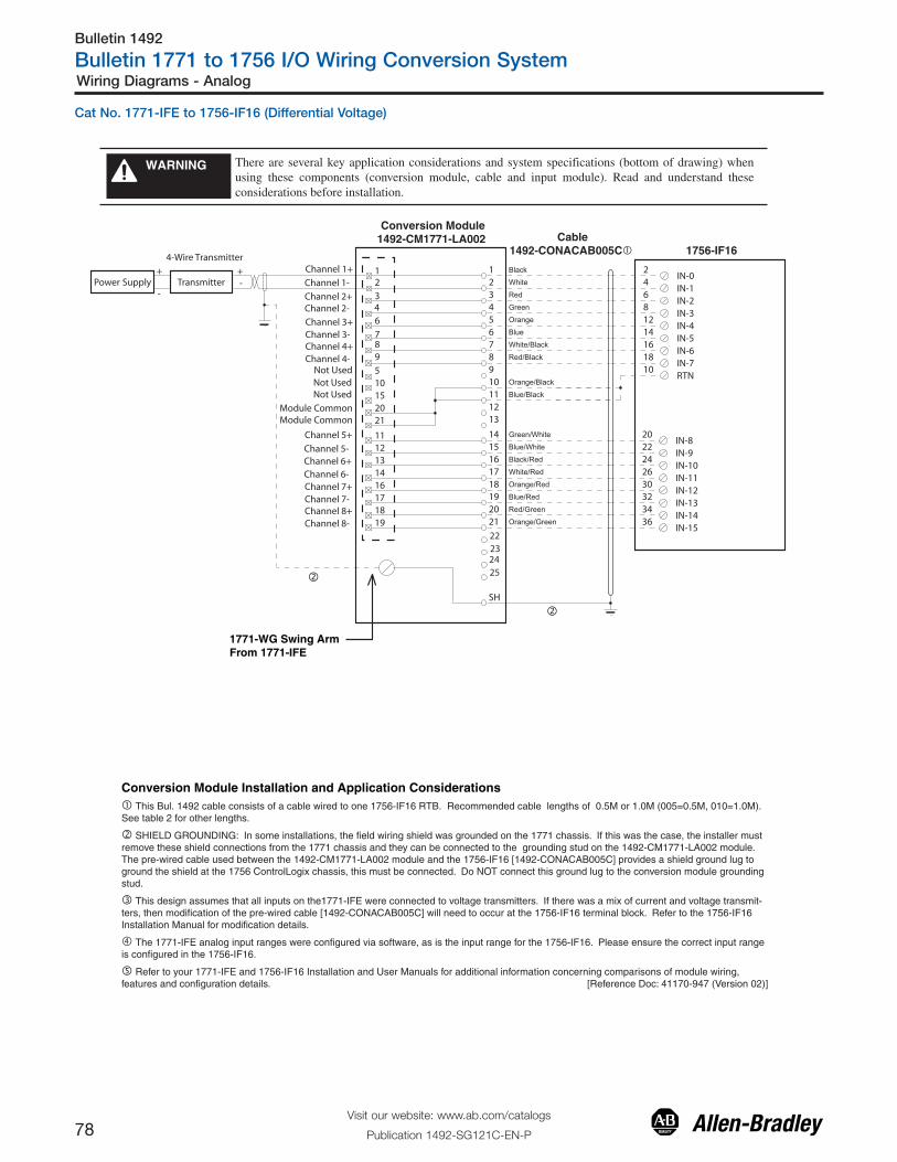
Bulletin 1492
Bulletin 1771 to 1756 I/O Wiring Conversion System
78Visit our website: www.ab.com/catalogs
Publication 1492-SG121C-EN-P
Wiring Diagrams - Analog
Cat No. 1771-IFE to 1756-IF16 (Differential Voltage)

Bulletin 1492
Bulletin 1771 to 1756 I/O Wiring Conversion System
79Visit our website: www.ab.com/catalogs
Publication 1492-SG121C-EN-P
Wiring Diagrams - Analog
Cat No. 1771-IFE to 1756-IF16 (Single-ended Current)
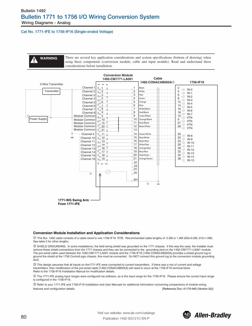
Bulletin 1492
Bulletin 1771 to 1756 I/O Wiring Conversion System
80Visit our website: www.ab.com/catalogs
Publication 1492-SG121C-EN-P
Wiring Diagrams - Analog
Cat No. 1771-IFE to 1756-IF16 (Single-ended Voltage)

Bulletin 1492
Bulletin 1771 to 1756 I/O Wiring Conversion System
81Visit our website: www.ab.com/catalogs
Publication 1492-SG121C-EN-P
Wiring Diagrams - Analog
Cat No. 1771-IFF to 1756-IF16 (Differential Current)

Bulletin 1492
Bulletin 1771 to 1756 I/O Wiring Conversion System
82Visit our website: www.ab.com/catalogs
Publication 1492-SG121C-EN-P
Wiring Diagrams - Analog
Cat No. 1771-IFF to 1756-IF16 (Differential Voltage)

Bulletin 1492
Bulletin 1771 to 1756 I/O Wiring Conversion System
83Visit our website: www.ab.com/catalogs
Publication 1492-SG121C-EN-P
Wiring Diagrams - Analog
Cat No. 1771-IFF to 1756-IF16 (Single-ended Current)

Bulletin 1492
Bulletin 1771 to 1756 I/O Wiring Conversion System
84Visit our website: www.ab.com/catalogs
Publication 1492-SG121C-EN-P
Wiring Diagrams - Analog
Cat No. 1771-IFF to 1756-IF16 (Single-ended Voltage)

Bulletin 1492
Bulletin 1771 to 1756 I/O Wiring Conversion System
85Visit our website: www.ab.com/catalogs
Publication 1492-SG121C-EN-P
Wiring Diagrams - Analog
Cat No. 1771-IL to 1756-IF6I (Voltage)

Bulletin 1492
Bulletin 1771 to 1756 I/O Wiring Conversion System
86Visit our website: www.ab.com/catalogs
Publication 1492-SG121C-EN-P
Wiring Diagrams - Analog
Cat No. 1771-IL to 1756-IF6I (Differential Current)

Bulletin 1492
Bulletin 1771 to 1756 I/O Wiring Conversion System
87Visit our website: www.ab.com/catalogs
Publication 1492-SG121C-EN-P
Wiring Diagrams - Analog
Cat No. 1771-IL to 1756-IF6I (Voltage - Qty. 2)

Bulletin 1492
Bulletin 1771 to 1756 I/O Wiring Conversion System
88Visit our website: www.ab.com/catalogs
Publication 1492-SG121C-EN-P
Wiring Diagrams - Analog
Conversion Module1492-CM1771-LA004
1771-WF Swing ArmFrom 1771-IL
Cable1492-CONACAB005T1� 1756-IF6I
1756-IF6I
Conversion Module Installation and Application Considerations� This Bul. 1492 cable consists of a cable wired to two 1756-IF6I RTB. Recommended cable lengths of 0.5M or 1.0M (005=0.5M, 010=1.0M). See table 2 for other lengths.
� SHIELD GROUNDING: In some installations, the field wiring shield was grounded on the 1771 chassis. If this was the case, the installer must remove these shield connections from the 1771 chassis and they can be connected to the grounding stud on the 1492-CM1771-LA004 module. The pre-wired cable used between the 1492-CM1771-LA004 module and the 1756-IF6I [1492-CONACAB005T1] provides a shield ground lug to ground the shield at the 1756 ControlLogix chassis, this must be connected. Do NOT connect this ground lug to the conversion module grounding stud.
� The 1771-IL input configuration was software configured, as is the 1756-IF6I. Please ensure the correct configuration in the 1756-IF6I.
� Refer to your 1771-IL and 1756-IF6I Installation and User Manuals for additional information concerning comparisons of module wiring, features and configuration details.
� This configuration uses two (2) 1756-IF6I output modules to replace a single 1771-IL output module. This may require the use of a larger 1756 I/O chassis and conversion mounting assembly. Ensure there is sufficient panel space to allow for this possibility. [Reference Doc: 41171-032 (Version 00)]
181716151413121110
987
SH
432
6
1
5
Orange/Red
White/Red
Green/White
Blue/White
Orange/Black
Red/White
Black/Red
Blue/Black
Black/White
Green/Black
Blue
Orange
Red/Black
White/Black
18
14131211
8
65
171615
4321
109
7
Channel6 Channel7Channel7 Black
White
RedGreen
Channel5 Channel5Channel6
Channel4Channel4
Channel3 Channel3
Channel0
Channel2Channel2
Channel1Channel1
Channel0 53
64
119
1210
1917
16152018
1
278
RET-0
IN-0/I
IN-1/V
IN-4/IRET-4IN-5/IRET-5
TransmitterPower Supply+
-
4-Wire Transmitter
+ -
RET-1
IN-1/I
IN-0/V
RET-3
IN-3/I
IN-2/VIN-3/V
RET-2IN-2/I
IN-4/VIN-5/V
2-WireTransmitter
+
-
��
53
64
119
1210
1917
16152018
1
278
RET-0
IN-0/I
IN-1/V
IN-4/IRET-4IN-5/IRET-5
RET-1
IN-1/I
IN-0/V
RET-3
IN-3/I
IN-2/VIN-3/V
RET-2IN-2/I
IN-4/VIN-5/V
Cat No. 1771-IL to 1756-IF6I (Current- Qty. 2)

Bulletin 1492
Bulletin 1771 to 1756 I/O Wiring Conversion System
89Visit our website: www.ab.com/catalogs
Publication 1492-SG121C-EN-P
Wiring Diagrams - Analog
Cat No. 1771- IR to 1756-IR6I

Bulletin 1492
Bulletin 1771 to 1756 I/O Wiring Conversion System
90Visit our website: www.ab.com/catalogs
Publication 1492-SG121C-EN-P
Wiring Diagrams - Analog
Cat No. 1771-IXE to 1756-IT6I2

Bulletin 1492
Bulletin 1771 to 1756 I/O Wiring Conversion System
91Visit our website: www.ab.com/catalogs
Publication 1492-SG121C-EN-P
Wiring Diagrams - Analog
Cat No. 1771-IXHR to 1756-IT6I2

Bulletin 1492
Bulletin 1771 to 1756 I/O Wiring Conversion System
92Visit our website: www.ab.com/catalogs
Publication 1492-SG121C-EN-P
Wiring Diagrams - Analog
Cat No. 1771-OFE1 to 1756-OF6VI

Bulletin 1492
Bulletin 1771 to 1756 I/O Wiring Conversion System
93Visit our website: www.ab.com/catalogs
Publication 1492-SG121C-EN-P
Wiring Diagrams - Analog
Cat No. 1771-OFE2 to 1756-OF6CI

Bulletin 1492
Bulletin 1771 to 1756 I/O Wiring Conversion System
94Visit our website: www.ab.com/catalogs
Publication 1492-SG121C-EN-P
Wiring Diagrams - High Resolution Isolated Analog
There are several key application considerations and system specifications (bottom of drawing) when using these components (conversion module, cable and input module). Read and understand these considerations before installation.
WARNING
�
�
�
�
�
Cable “B”1492-CONACAB020N2�
Cable “A”1492-CONACAB020N2�
Interface Module 1771-RTP4
1756-IF6CIS
1756-IF6CISB1B2B3B4B5A4A5B8B9A6A7B12B13A8A9B16B17A10A11
W2SH
W3
I8
I7
I6
I5
I4
I3
I1
I2
R8
R7
R6
R5
R4
R3
R2
R1CURRENT LOAD
A1A2A3B12B13A12A13B14B15A14A15B16B17A16A17B18B19
A18A19
CRW1
CL
O8
O7
O6
O5
O4
O3
O1
O2
S8
S7
S6
S5
S4
S3
S2
S1
1516
1819
2122
24 53
46
119
10
12
Black
Brown
Green
Yellow
White/Black
White/Red
Violet
Red
I-OUT-0
I-OUT-1
I-OUT-2
I-OUT-3
I-RTN-0
I-RTN-2
I-RTN-3
N/A
N/A
N/A
25
N/A
N/A
N/A
-
I-RTN-1
CURRENT LOAD
+
-24VDCSUPPLY
24VDCSUPPLY
+
53
46
119
10
12
I-OUT-0
I-OUT-1
I-OUT-2
I-OUT-3
I-RTN-0
I-RTN-2
I-RTN-3
I-RTN-1
Black
Brown
Green
Yellow
White/Black
White/Red
Violet
Red1516
1819
2122
2425
Conversion Module Installation and Application Considerations� Cables are available in 2.0m, or 5.0m
� Terminals starting with A are the lower row of terminals, B terminals are the upper row.
� Follow your PLC Analog User Manual for proper shield grounding instructions.
� RTN terminals are internally connected on the 1756-IF6CIS.
� Terminals w1, w2, w3, are spares used for field wire convenience. NOTE: This is only true for module RTP4. The Bul. 1492 cable does not connect to these terminals. [Reference Doc: 41171-073 (Version 00)]
Cat No. 1771-NIS to 1756-IF6CIS (Qty. 2)

Bulletin 1492
Bulletin 1771 to 1756 I/O Wiring Conversion System
95Visit our website: www.ab.com/catalogs
Publication 1492-SG121C-EN-P
Wiring Diagrams - High Resolution Isolated Analog
There are several key application considerations and system specifications (bottom of drawing) when using these components (conversion module, cable and input module). Read and understand these considerations before installation.
WARNING
�
�
���
���
�
�
�
Cable “B”1492-CONACAB020N3�
Cable “A”1492-CONACAB020N3�
Interface Module 1771-RTP3
1756-IF6I
1756-IF6I
B1B2B3B4B5A4A5B8B9A6A7B12B13A8A9B16B17A10A11
W2SH
W3
I8
I7
I6
I5
I4
I3
I1
I2
R8
R7
R6
R5
R4
R3
R2
R1
A1A2A3B12B13A12A13B14B15A14A15B16B17A16A17B18B19
A18A19
CRW1
CL
O8
O7
O6
O5
O4
O3
O1
O2
S8
S7
S6
S5
S4
S3
S2
S1
1516
1819
2122
2425 3
5
46
119
10
12
BlackWhite
Green
Orange
White/Black
White/Red
White/Orange
Gray
IN-0/I
IN-1/I
IN-2/I
IN-3/I
RTN-0
RTN-2
RTN-3
N/A
N/A
N/A
N/A
N/A
N/A
RTN-1
1 IN-0/V
2 IN-1/V
7 IN-2/V
8 IN-3/V
35
46
119
10
12
BlackWhite
Green
Orange
White/Black
White/Red
White/Orange
Gray
1
2
7
8
CURRENT LOAD
-
CURRENT LOAD
+
-24VDCSUPPLY
24VDCSUPPLY
+
1516
1819
2122
2425 IN-0/I
IN-1/I
IN-2/I
IN-3/I
RTN-0
RTN-2
RTN-3
RTN-1
IN-0/V
IN-1/V
IN-2/V
IN-3/V
Conversion Module Installation and Application Considerations� Cables are available in 2.0m, or 5.0m
� Terminals starting with A are the lower row of terminals, B terminals are the upper row.
� Follow your PLC Analog User Manual for proper shield grounding instructions.
� RTN terminals are internally connected on the 1756-IF6I.
� Terminals w1, w2, w3, are spares used for field wire convenience. NOTE: This is only true for module RTP3. The Bul. 1492 cable does not connect to these terminals. [Reference Doc: 41171-074 (Version 00)]
Cat No. 1771-NIV to 1756-IF6I (Current - Qty. 2)

Bulletin 1492
Bulletin 1771 to 1756 I/O Wiring Conversion System
96Visit our website: www.ab.com/catalogs
Publication 1492-SG121C-EN-P
Wiring Diagrams - High Resolution Isolated Analog
There are several key application considerations and system specifications (bottom of drawing) when using these components (conversion module, cable and input module). Read and understand these considerations before installation.
WARNING
�
�
�
�
�
Cable “A”1492-CONACAB020N7�
Cable “B”1492-CONACAB020N7�
Interface Module1771-RTP4
1756-IF6I
1756-IF6I
B1B2B3B4B5A4A5B8B9A6A7B12B13A8A9B16B17A10A11
W2SH
W3
I8
I7
I6
I5
I4
I3
I1
I2
R8
R7
R6
R5
R4
R3
R2
R1VOLTAGE LOAD
A1A2A3B12B13A12A13B14B15A14A15B16B17A16A17B18B19
A18A19
CRW1
CL
O8
O7
O6
O5
O4
O3
O1
O2
S8
S7
S6
S5
S4
S3
S2
S1
1516
1819
2122
2425 1
5
26
117
8
12
VioletBlack
Green
Red
White/Black
White/Red
Yellow
Brown
IN-0V
IN-1V
IN-2V
IN-3V
RTN-0
RTN-2
RTN-3
N/A
N/A
N/A
N/A
N/A
N/A
+
-
RTN-1
15
26
117
8
12
VOLTAGE LOAD
+
-
IN-0V
IN-1V
IN-2V
IN-3V
RTN-0
RTN-2
RTN-3
RTN-1
1516
1918
2221
2425 Violet
Black
Green
Red
White/Black
White/Red
Yellow
Brown
Conversion Module Installation and Application Considerations� Cables are available in 2.0m, or 5.0m
� Terminals starting with A are the lower row of terminals, B terminals are the upper row.
� Follow your PLC Analog User Manual for proper shield grounding instructions.
� RTN terminals are internally connected on the 1756-IF6I.
� Terminals w1, w2, w3, are spares used for field wire convenience. NOTE: This is only true for module RTP4. The Bul. 1492 cable does not connect to these terminals. [Reference Doc: 41171-080 (Version 00)]
Cat No. 1771-NIV to 1756-IF6I (Voltage - Qty. 2)

Bulletin 1492
Bulletin 1771 to 1756 I/O Wiring Conversion System
97Visit our website: www.ab.com/catalogs
Publication 1492-SG121C-EN-P
Wiring Diagrams - High Resolution Isolated Analog
�
�
Conversion Module Installation and Application Considerations� Cables are available in 2.0m, or 5.0m
� Terminals starting with A are the lower row of terminals, B terminals are the upper row.
� Follow your PLC Analog User Manual for proper shield grounding instructions.
� RTN terminals are internally connected on the 1756-IF6I.
� Terminals w1, w2, w3, are spares used for field wire convenience. NOTE: This is only true for module RTP3. The Bul. 1492 cable does not connect to these terminals. [Reference Doc: 41171-038 (Version 00)]
Interface Module1771-RTP4
There are several key application considerations and system specifications (bottom of drawing) when using these components (conversion module, cable and input module). Read and understand these considerations before installation.
WARNING
Cable “A”1492-CONACAB010N7
(Voltage)�
Cable “B”1492-CONACAB010N3
(Current)�
B1B2B3B4B5A4A5B8B9A6A7B12B13A8A9B16B17A10A11
W2SH
W3
I8
I7
I6
I5
I4
I3
I1
I2
R8
R7
R6
R5
R4
R3
R2
R1
A1A2A3B12B13A12A13B14B15A14A15B16B17A16A17B18B19
A18A19
CRW1
CL
O8
O7
O6
O5
O4
O3
O1
O2
S8
S7
S6
S5
S4
S3
S2
S1
1516
1819
2122
2425 Black
White
Green
Orange
White/Black
White/Red
White/Orange
Gray
N/A
N/A
N/A
N/A
N/A
N/A
BlackWhite
Green
Orange
White/Black
White/Red
White/Orange
Gray
Voltage LOAD
-
CURRENT LOAD
+
-
+
1516
1819
2122
2425
35
46
119
10
12
IN-0/I
IN-1/I
IN-2/I
IN-3/I
RTN-0
RTN-2
RTN-3
RTN-1
1 IN-0/V
2 IN-1/V
7 IN-2/V
8 IN-3/V
�
�
1756-IF6I
1756-IF6I
15
26
117
8
12
IN-0V
IN-1V
IN-2V
IN-3V
RTN-0
RTN-2
RTN-3
RTN-1
�
Cat No. 1771-NIV to 1756-IF6I (Qty. 2, Current and Voltage)

Bulletin 1492
Bulletin 1771 to 1756 I/O Wiring Conversion System
98Visit our website: www.ab.com/catalogs
Publication 1492-SG121C-EN-P
Wiring Diagrams - High Resolution Isolated Analog
There are several key application considerations and system specifications (bottom of drawing) when using these components (conversion module, cable and input module). Read and understand these considerations before installation.
WARNING
�
Conversion Module Installation and Application Considerations� Cables are available in 2.0m, or 5.0m
� Terminals starting with A are the lower row of terminals, B terminals are the upper row.
� Follow your PLC Analog User Manual for proper shield grounding instructions.
� RTN terminals are internally connected on the 1756-IF6I.
� Terminals w1, w2, w3, are spares used for field wire convenience. NOTE: This is only true for module RTP4. The Bul. 1492 cable does not connect to these terminals. [Reference Doc: 41171-039 (Version 00)]
Cable “A”1492-CONACAB010N3
(Current)�
Cable “B”1492-CONACAB020N7
(Voltage)�
��
�
Interface Module 1771-RTP4
1756-IF6I
B1B2B3B4B5A4A5B8B9A6A7B12B13A8A9B16B17A10A11
W2SH
W3
I8
I7
I6
I5
I4
I3
I1
I2
R8
R7
R6
R5
R4
R3
R2
R1CURRENT LOAD
A1A2A3B12B13A12A13B14B15A14A15B16B17A16A17B18B19
A18A19
CRW1
CL
O8
O7
O6
O5
O4
O3
O1
O2
S8
S7
S6
S5
S4
S3
S2
S1
1516
1819
2122
2425 Violet
Black
Red
White/Black
White/Red
Yellow
Brown
N/A
N/A
N/A
N/A
N/A
N/A
+
-
15
26
117
8
12
VOLTAGE LOAD
+
-
IN-0V
IN-1V
IN-2V
IN-3V
RTN-0
RTN-2
RTN-3
RTN-1
1516
1918
2221
2425 Violet
Black
Green
Red
White/Black
White/Red
Yellow
Brown
35
46
119
10
12
Green
IN-0/I
IN-1/I
IN-2/I
IN-3/I
RTN-0
RTN-2
RTN-3
1756-IF6I
RTN-1
1 IN-0/V
2 IN-1/V
7 IN-2/V
8 IN-3/V
�
Cat No. 1771-NIV to 1756-IF6I (Qty. 2, Voltage and Current)

Bulletin 1492
Bulletin 1771 to 1756 I/O Wiring Conversion System
99Visit our website: www.ab.com/catalogs
Publication 1492-SG121C-EN-P
Wiring Diagrams - High Resolution Isolated Analog
There are several key application considerations and system specifications (bottom of drawing) when using these components (conversion module, cable and input module). Read and understand these considerations before installation.
WARNING
�
�
�
�
�
Cable “A”1492-CONACAB020N7�
Cable “B”1492-CONACAB020N7�
Interface Module 1771-RTP4
1756-IF6I
1756-IF6I
B1B2B3B4B5A4A5B8B9A6A7B12B13A8A9B16B17A10A11
W2SH
W3
I8
I7
I6
I5
I4
I3
I1
I2
R8
R7
R6
R5
R4
R3
R2
R1VOLTAGE LOAD
A1A2A3B12B13A12A13B14B15A14A15B16B17A16A17B18B19
A18A19
CRW1
CL
O8
O7
O6
O5
O4
O3
O1
O2
S8
S7
S6
S5
S4
S3
S2
S1
1516
1819
2122
2425 1
5
26
117
8
12
VioletBlack
Green
Red
White/Black
White/Red
Yellow
Brown
IN-0V
IN-1V
IN-2V
IN-3V
RTN-0
RTN-2
RTN-3
N/A
N/A
N/A
N/A
N/A
N/A
+
-
RTN-1
15
26
117
8
12
VOLTAGE LOAD
+
-
IN-0V
IN-1V
IN-2V
IN-3V
RTN-0
RTN-2
RTN-3
RTN-1
VioletBlack
Green
Red
White/Black
White/Red
Yellow
Brown
1516
1819
2122
2425
Conversion Module Installation and Application Considerations� Cables are available in 2.0m, or 5.0m
� Terminals starting with A are the lower row of terminals, B terminals are the upper row.
� Follow your PLC Analog User Manual for proper shield grounding instructions.
� RTN terminals are internally connected on the 1756-IF6I.
� Terminals w1, w2, w3, are spares used for field wire convenience. NOTE: This is only true for module RTP4. The Bul. 1492 cable does not connect to these terminals. [Reference Doc: 41171-078 (Version 00)]
Cat No. 1771-NIV1 to 1756-IF6I (Qty. 2, Voltage)

Bulletin 1492
Bulletin 1771 to 1756 I/O Wiring Conversion System
100Visit our website: www.ab.com/catalogs
Publication 1492-SG121C-EN-P
Wiring Diagrams - High Resolution Isolated Analog
There are several key application considerations and system specifications (bottom of drawing) when using these components (conversion module, cable and input module). Read and understand these considerations before installation.
WARNING
1756-OF6CI
1756-OF6CI
�
�
�
�
�
Cable “A”1492-CONACAB020N1�
Cable “B”1492-CONACAB020N1�
B1B2B3B4B5A4A5B8B9A6A7B12B13A8A9B16B17A10A11
Interface Module 1771-RTP3 or RTP4
W2SH
W3
I8
I7
I6
I5
I4
I3
I1
I2
R8
R7
R6
R5
R4
R3
R2
R1CURRENT LOAD
A1A2A3B12B13A12A13B14B15A14A15B16B17A16A17B18B19
A18A19
CRW1
CL
O8
O7
O6
O5
O4
O3
O1
O2
S8
S7
S6
S5
S4
S3
S2
S1
15
418
721
1024 5
1
2
6
11
7
8
12
Black
White
Green
Orange
White/Black
White/Red
White/Orange
Gray
Black
White
Green
Orange
White/Black
White/Red
White/Orange
Gray
OUT-0
OUT-1
OUT-2
OUT-3
RTN-0
RTN-1
RTN-2
RTN-3
N/A
N/A
N/A
13
5
1
2
6
11
7
8
12
N/A
N/A
N/A
+
-
OUT-0
OUT-1
OUT-2
OUT-3
RTN-0
RTN-1
RTN-2
RTN-315
418
721
1024
13
Conversion Module Installation and Application Considerations� Cables are available in 2.0m, or 5.0m
� Terminals starting with A are the lower row of terminals, B terminals are the upper row.
� Follow your PLC Analog User Manual for proper shield grounding instructions.
� RTN terminals are internally connected on the 1756-OF6CI.
� Terminals w1, w2, w3, are spares used for field wire convenience. NOTE: This is only true for modules RTP3 and RTP4. The Bul. 1492 cable does not connect to these terminals. [Reference Doc: 41171-072 (Version 00)]
Cat No. 1771-NOC to 1756-OF6CI (Qty. 2)

Bulletin 1492
Bulletin 1771 to 1756 I/O Wiring Conversion System
101Visit our website: www.ab.com/catalogs
Publication 1492-SG121C-EN-P
Wiring Diagrams - High Resolution Isolated Analog
There are several key application considerations and system specifications (bottom of drawing) when using these components (conversion module, cable and input module). Read and understand these considerations before installation.
WARNING
�
�
�
Cable “A”1492-CONACAB020N8�
Cable “B”1492-CONACAB020N8�
Interface Module 1771-RTP3 or 1771-RTP4 1756-OF8�
B1B2B3B4B5A4A5B8B9A6A7B12B13A8A9B16B17A10A11
W2SH
W3
I8
I7
I6
I5
I4
I3
I1
I2
R8
R7
R6
R5
R4
R3
R2
R1CURRENT LOAD
A1A2A3B12B13A12A13B14B15A14A15B16B17A16A17B18B19
A18A19
CRW1
CL
O8
O7
O6
O5
O4
O3
O1
O2
S8
S7
S6
S5
S4
S3
S2
S1
15
418
721
1024
13
5
3
15
418
72122
1024
13
9
15
13
19
Black
White
Green
Orange
White/Black
White/Red
White/Orange
Gray
Black
White
Green
Orange
White/Black
White/Red
White/Orange
Gray
I-OUT-0
I-OUT-1
I-OUT-2
I-OUT-3
I-RTN
I-RTN
6
4
10
16
14
20
I-OUT-4
I-OUT-5
I-OUT-6
I-OUT-7
I-RTN
I-RTN
Conversion Module Installation and Application Considerations� Cables are available in 2.0m, or 5.0m
� Terminals starting with A are the lower row of terminals, B terminals are the upper row.
� Follow your PLC Analog User Manual for proper shield grounding instructions.
� RTN terminals are internally connected on the 1756-OF8.
� Terminals w1, w2, w3, are spares used for field wire convenience. NOTE: This is only true for module RTP3 and RTP4. The Bul. 1492 cable does not connect to these terminals.
� The 1771-NOC module provides channel to channel isolation, the 1756-OF8 does not. A conversion from 1771-NOC to an isolated 1756-OF8 is avalible. [Reference Doc: 41171-079 (Version 00)]
Cat No. 1771-NOC to 1756-OF8

Bulletin 1492
Bulletin 1771 to 1756 I/O Wiring Conversion System
102Visit our website: www.ab.com/catalogs
Publication 1492-SG121C-EN-P
Wiring Diagrams - High Resolution Isolated Analog
There are several key application considerations and system specifications (bottom of drawing) when using these components (conversion module, cable and input module). Read and understand these considerations before installation.
WARNING
1756-OF6VI
1756-OF6VI
�
�
�
�
�
Cable “A”1492-CONACAB020N1�
Cable “B”1492-CONACAB020N1�
B1B2B3B4B5A4A5B8B9A6A7B12B13A8A9B16B17A10A11
Interface Module 1771-RTP3 or RTP4
W2SH
W3
I8
I7
I6
I5
I4
I3
I1
I2
R8
R7
R6
R5
R4
R3
R2
R1VOLTAGE LOAD
A1A2A3B12B13A12A13B14B15A14A15B16B17A16A17B18B19
A18A19
CRW1
CL
O8
O7
O6
O5
O4
O3
O1
O2
S8
S7
S6
S5
S4
S3
S2
S1
15
418
721
1024 5
1
2
6
11
7
8
12
Black
White
Green
Orange
White/Black
White/Red
White/Orange
Gray
Black
White
Green
Orange
White/Black
White/Red
White/Orange
Gray
OUT-0
OUT-1
OUT-2
OUT-3
RTN-0
RTN-1
RTN-2
RTN-3
N/A
N/A
N/A
13
5
1
2
6
11
7
8
12
N/A
N/A
N/A
+
-
OUT-0
OUT-1
OUT-2
OUT-3
RTN-0
RTN-1
RTN-2
RTN-315
418
721
1024
13
Conversion Module Installation and Application Considerations� Cables are available in 2.0m, or 5.0m
� Terminals starting with A are the lower row of terminals, B terminals are the upper row.
� Follow your PLC Analog User Manual for proper shield grounding instructions.
� RTN terminals are internally connected on the 1756-OF6VI.
� Terminals w1, w2, w3, are spares used for field wire convenience. NOTE: This is only true for modules RTP3 and RTP4. The Bul. 1492 cable does not connect to these terminals. [Reference Doc: 41171-081 (Version 00)]
Cat No. 1771-NOV to 1756-OF6VI (Qty. 2)

Bulletin 1492
Bulletin 1771 to 1756 I/O Wiring Conversion System
103Visit our website: www.ab.com/catalogs
Publication 1492-SG121C-EN-P
Wiring Diagrams - High Resolution Isolated Analog
There are several key application considerations and system specifications (bottom of drawing) when using these components (conversion module, cable and input module). Read and understand these considerations before installation.
WARNING
�
�
�
Cable “B”1492-CONACAB020N4�
Cable “A”1492-CONACAB020N4�
Interface Module 1771-RTP4
1756-IR6I
1756-IR6I
B1B2B3B4B5A4A5B8B9A6A7B12B13A8A9B16B17A10A11
W2SH
W3
I8
I7
I6
I5
I4
I3
I1
I2
R8
R7
R6
R5
R4
R3
R2
R1
A1A2A3B12B13A12A13B14B15A14A15B16B17A16A17B18B19
A18A19
CRW1
CL
O8
O7
O6
O5
O4
O3
O1
O2
S8
S7
S6
S5
S4
S3
S2
S1
2425 3
1
Black
White
GreenOrange
White/Black
White/Red
Gray
IN-0/BIN-0/A
N/A
N/A
N/A
13
N/A
N/A
N/A
RTD TRANSMITTER
5 RTN-0
White/Orange
Violet
Brown
Yellow
Red
22
10
721
41819
1516
4
2
6
9
7
11
10
8
12
IN-1/B
IN-1/A
RTN-1
IN-2/B
IN-2/A
RTN-2
IN-3/A
IN-3/BRTN-3
242513
22
10
721
41819
1516
RTD TRANSMITTER
31
IN-0/BIN-0/A
5 RTN-0
4
2
6
9
7
11
10
8
12
IN-1/B
IN-1/A
RTN-1
IN-2/B
IN-2/A
RTN-2
IN-3/B
IN-3/A
RTN-3
Conversion Module Installation and Application Considerations� Cables are available in 2.0m, or 5.0m
� Terminals starting with A are the lower row of terminals, B terminals are the upper row.
� Follow your PLC Analog User Manual for proper shield grounding instructions.
� RTN terminals are internally connected on the 1756-IR6I.
� Terminals w1, w2, w3, are spares used for field wire convenience. NOTE: This is only true for module RTP4. The Bul. 1492 cable does not connect to these terminals. [Reference Doc: 41171-075 (Version 00)]
Cat No. 1771-NR to 1756-IR6I

Bulletin 1492
Bulletin 1771 to 1756 I/O Wiring Conversion System
104Visit our website: www.ab.com/catalogs
Publication 1492-SG121C-EN-P
Wiring Diagrams - High Resolution Isolated Analog
41171-076 (02)
B1A1B2B3A2A3B4B5A4A5
B6B7A6A7B8B9A9A8
1771-RT41
3
2W1SH
I4
I3
I2
I1
R4
R3
R2
R1
1756-IT6I4
O4
O3
O2
O1
S4
S3
S2
S1
1492-CONACAB020N5
CONVERSION MODULE INSTALLATION AND APPLICATION CONSIDERATIONS
1516
1918
2524
2122
+
-
Black
Red
Green
Brown
White/Black
White/Red
Yellow
Violet
THERMOCOUPLE
15
62
711
812
RTN-0
RTN-1
RTN-2
RTN-3
IN-0
IN-2
IN-3
IN-1
� Cables are available in 2.0M or 5.0M.� Terminals starting with A are the lower row of terminals, B terminals are the upper row.� Follow your PLC Analog User Manual for proper shield grounding instructions.� Terminals W1, W2 and W3 are spares used for field wire convenience. NOTE. This is only true for modules RT41 . The Bul. 1492 cable does not connect to these terminals.
CJC+
CJC-Thermocouple
10
14
Cable “B”
B1A1B2B3A2A3B4B5A4A5
B6B7A6A7B8B9A9A8
1771-RT41
2W1SH
I4
I3
I2
I1
R4
R3
R2
R1
1756-IT6I4
O4
O3
O2
O1
S4
S3
S2
S1
1492-CONACAB020N5
1516
1918
2524
2122
+
-
Black
Red
Green
Brown
White/Black
White/Red
Yellow
Violet
THERMOCOUPLE
15
62
711
812
RTN-0
RTN-1
RTN-2
RTN-3
IN-0
IN-2
IN-3
IN-1
CJC+
CJC-Thermocouple
10
14
Cable “A”
3
1
1
White/Violet
White/Grey
White/Violet
White/Grey
There are several key application considerations and system specifications (bottom of drawing) when using these components (conversion module, cable and input module). Read and understand these considerations before installation.
WARNING
Cat No. 1771-NT1 to 1756-IT6I (Qty. 2)

Bulletin 1492
Bulletin 1771 to 1756 I/O Wiring Conversion System
105Visit our website: www.ab.com/catalogs
Publication 1492-SG121C-EN-P
Wiring Diagrams - High Resolution Isolated Analog
41171-086 (00)
B1A1B2B3A2A3B4B5A4A5
B6B7A6A7B8B9A9A8
1771-RT41
3
2W1SH
I4
I3
I2
I1
R4
R3
R2
R1
1756-IT6I24
O4
O3
O2
O1
S4
S3
S2
S1
1492-CONACAB020N6
CONVERSION MODULE INSTALLATION AND APPLICATION CONSIDERATIONS
1516
1918
2524
2122
+
-
Black
Red
Green
Brown
White/Black
White/Red
Yellow
Violet
THERMOCOUPLE
56
87
910
1112
RTN-0
RTN-1
RTN-2
RTN-3
IN-0
IN-2
IN-3
IN-1
� Cables are available in 2.0M or 5.0M.� Terminals starting with A are the lower row of terminals, B terminals are the upper row.� Follow your PLC Analog User Manual for proper shield grounding instructions.� Terminals W1, W2 and W3 are spares used for field wire convenience. NOTE. This is only true for modules RT41 . The Bul. 1492 cable does not connect to these terminals.
CJC+
CJC-Thermocouple
3
4
Cable “B”
B1A1B2B3A2A3B4B5A4A5
B6B7A6A7B8B9A9A8
1771-RT41
2W1SH
I4
I3
I2
I1
R4
R3
R2
R1
1756-IT6I24
O4
O3
O2
O1
S4
S3
S2
S1
1492-CONACAB020N6
1516
1918
2524
2122
+
-
Black
Red
Green
Brown
White/Black
White/Red
Yellow
Violet
THERMOCOUPLE
56
87
910
1112
RTN-0
RTN-1
RTN-2
RTN-3
IN-0
IN-2
IN-3
IN-1
CJC+
CJC-Thermocouple
3
4
Cable “A”
3
1
1
White/Violet
White/Grey
White/Violet
White/Grey
There are several key application considerations and system specifications (bottom of drawing) when using these components (conversion module, cable and input module). Read and understand these considerations before installation.
WARNING
Cat No. 1771-NT1 to 1756-IT6I2 (Qty. 2)

Bulletin 1492
Bulletin 1771 to 1756 I/O Wiring Conversion System
106Visit our website: www.ab.com/catalogs
Publication 1492-SG121C-EN-P
Wiring Diagrams - High Resolution Isolated Analog
41171-077 (01)
B1A1B2B3A2A3B4B5A4A5
B6B7A6A7B8B9A9A8
1771-RT41
3
2W1SH
I4
I3
I2
I1
R4
R3
R2
R1
1756-IT6I24
O4
O3
O2
O1
S4
S3
S2
S1
1492-CONACAB020N6
CONVERSION MODULE INSTALLATION AND APPLICATION CONSIDERATIONS
1516
1918
2524
2122
+
-
Black
Red
Green
Brown
White/Black
White/Red
Yellow
Violet
THERMOCOUPLE
56
87
910
1112
RTN-0
RTN-1
RTN-2
RTN-3
IN-0
IN-2
IN-3
IN-1
� Cables are available in 2.0M or 5.0M.� Terminals starting with A are the lower row of terminals, B terminals are the upper row.� Follow your PLC Analog User Manual for proper shield grounding instructions.� Terminals W1, W2 and W3 are spares used for field wire convenience. NOTE. This is only true for modules RT41 . The Bul. 1492 cable does not connect to these terminals.
CJC+
CJC-Thermocouple
3
4
Cable “B”
B1A1B2B3A2A3B4B5A4A5
B6B7A6A7B8B9A9A8
1771-RT41
2W1SH
I4
I3
I2
I1
R4
R3
R2
R1
1756-IT6I24
O4
O3
O2
O1
S4
S3
S2
S1
1492-CONACAB020N6
1516
1918
2524
2122
+
-
Black
Red
Green
Brown
White/Black
White/Red
Yellow
Violet
THERMOCOUPLE
56
87
910
1112
RTN-0
RTN-1
RTN-2
RTN-3
IN-0
IN-2
IN-3
IN-1
CJC+
CJC-Thermocouple
3
4
Cable “A”
3
1
1
White/Violet
White/Grey
White/Violet
White/Grey
There are several key application considerations and system specifications (bottom of drawing) when using these components (conversion module, cable and input module). Read and understand these considerations before installation.
WARNING
Cat No. 1771-NT2 to 1756-IT6I2 (Qty. 2)
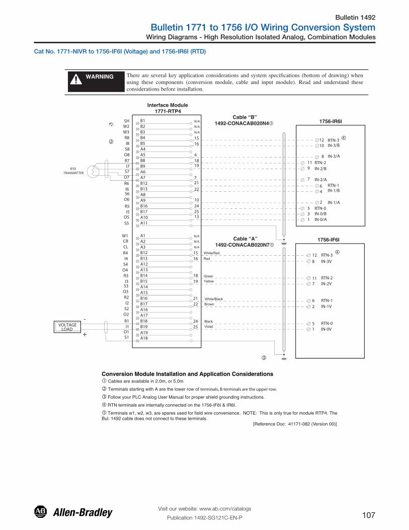
Bulletin 1492
Bulletin 1771 to 1756 I/O Wiring Conversion System
107Visit our website: www.ab.com/catalogs
Publication 1492-SG121C-EN-P
Wiring Diagrams - High Resolution Isolated Analog, Combination Modules
There are several key application considerations and system specifications (bottom of drawing) when using these components (conversion module, cable and input module). Read and understand these considerations before installation.
WARNING
�
�
�
Cable “A”1492-CONACAB020N7�
Cable “B”1492-CONACAB020N4�
Interface Module 1771-RTP4
1756-IF6I
B1B2B3B4B5A4A5B8B9A6A7B12B13A8A9B16B17A10A11
W2SH
W3
I8
I7
I6
I5
I4
I3
I1
I2
R8
R7
R6
R5
R4
R3
R2
R1VOLTAGE LOAD
A1A2A3B12B13A12A13B14B15A14A15B16B17A16A17B18B19
A18A19
CRW1
CL
O8
O7
O6
O5
O4
O3
O1
O2
S8
S7
S6
S5
S4
S3
S2
S1
1516
1819
2122
2425 1
5
26
117
8
12
VioletBlack
Green
Red
White/Black
White/Red
Yellow
Brown
IN-0V
IN-1V
IN-2V
IN-3V
RTN-0
RTN-2
RTN-3
N/A
N/A
N/A
N/A
N/A
N/A
+
-
RTN-1
�
1756-IR6I
242513
22
10
721
41819
1516
RTD TRANSMITTER
31
IN-0/BIN-0/A
5 RTN-0
4
2
6
9
7
11
10
8
12
IN-1/B
IN-1/A
RTN-1
IN-2/B
IN-2/A
RTN-2
IN-3/B
IN-3/A
RTN-3
Conversion Module Installation and Application Considerations� Cables are available in 2.0m, or 5.0m
� Terminals starting with A are the lower row of terminals, B terminals are the upper row.
� Follow your PLC Analog User Manual for proper shield grounding instructions.
� RTN terminals are internally connected on the 1756-IF6I & IR6I.
� Terminals w1, w2, w3, are spares used for field wire convenience. NOTE: This is only true for module RTP4. The Bul. 1492 cable does not connect to these terminals. [Reference Doc: 41171-082 (Version 00)]
Cat No. 1771-NIVR to 1756-IF6I (Voltage) and 1756-IR6I (RTD)

Bulletin 1492
Bulletin 1771 to 1756 I/O Wiring Conversion System
108Visit our website: www.ab.com/catalogs
Publication 1492-SG121C-EN-P
Wiring Diagrams - High Resolution Isolated Analog, Combination Modules
There are several key application considerations and system specifications (bottom of drawing) when using these components (conversion module, cable and input module). Read and understand these considerations before installation.
WARNING
�
Cable “B”1492-CONACAB020N4�
Interface Module 1771-RTP4
B1B2B3B4B5A4A5B8B9A6A7B12B13A8A9B16B17A10A11
W2SH
W3
I8
I7
I6
I5
I4
I3
I1
I2
R8
R7
R6
R5
R4
R3
R2
R1VOLTAGE LOAD
A1A2A3B12B13A12A13B14B15A14A15B16B17A16A17B18B19
A18A19
CRW1
CL
O8
O7
O6
O5
O4
O3
O1
O2
S8
S7
S6
S5
S4
S3
S2
S1
N/A
N/A
N/A
N/A
N/A
N/A
+
-
�
1756-IR6I
242513
22
10
721
41819
1516
RTD TRANSMITTER
31
IN-0/BIN-0/A
5 RTN-0
4
2
6
9
7
11
10
8
12
IN-1/B
IN-1/A
RTN-1
IN-2/B
IN-2/A
RTN-2
IN-3/B
IN-3/A
RTN-3
�
�
Cable “A”1492-CONACAB020N3�
1756-IF6I
1516
1819
2122
2425 3
5
46
119
10
12
BlackWhite
Green
Orange
White/Black
White/Red
White/Orange
Gray
IN-0/I
IN-1/I
IN-2/I
IN-3/I
RTN-0
RTN-2
RTN-3
RTN-1
1 IN-0/V
2 IN-1/V
7 IN-2/V
8 IN-3/V
Conversion Module Installation and Application Considerations� Cables are available in 2.0m, or 5.0m
� Terminals starting with A are the lower row of terminals, B terminals are the upper row.
� Follow your PLC Analog User Manual for proper shield grounding instructions.
� RTN terminals are internally connected on the 1756-IF6I & IR6I.
� Terminals w1, w2, w3, are spares used for field wire convenience. NOTE: This is only true for module RTP4. The Bul. 1492 cable does not connect to these terminals. [Reference Doc: 41171-083 (Version 00)]
Cat No. 1771-NIVR to 1756-IF6I (Current) and 1756-IR6I (RTD)

Bulletin 1492
Bulletin 1771 to 1756 I/O Wiring Conversion System
109Visit our website: www.ab.com/catalogs
Publication 1492-SG121C-EN-P
Wiring Diagrams - High Resolution Isolated Analog, Combination Modules
There are several key application considerations and system specifications (bottom of drawing) when using these components (conversion module, cable and input module). Read and understand these considerations before installation.
WARNING
Conversion Module Installation and Application Considerations Cables are available in 2.0m, or 5.0m
Terminals starting with A are the lower row of terminals, B terminals are the upper row.
Follow your PLC Analog User Manual for proper shield grounding instructions.
RTN terminals are internally connected on the 1756-IF6I.
Terminals w1, w2, w3, are spares used for field wire convenience. NOTE: This is only true for module RTP4. The Bul. 1492 cable does not connect to these terminals. [Reference Doc: 41171-084 (Version 00)]
B1B2B3B4B5A4A5B8B9A6A7B12B13A8A9B16B17A10A11
2W2SH
W3
I8
I7
I6
I5
I4
I3
I1
I2
R8
R7
R6
R5
R4
R3
R2
R1
4
A1A2A3B12B13A12A13B14B15A14A15B16B17A16A17B18B19
A18A19
CRW1
CL
O8
O7
O6
O5
O4
O3
O1
O2
S8
S7
S6
S5
S4
S3
S2
S1
CABLE “B”
1492-CONACAB010N5Cable “B”
1516
1918
2524
2122
+
-
Black
Red
Green
Brown
White/Black
White/Red
Yellow
Violet
THERMOCOUPLE
56
87
910
1112
RTN-0
RTN-1
RTN-2
RTN-3
IN-0
IN-2
IN-3
IN-1
CJC+CJC-
Thermocouple
Cable “A”1492-CONACAB020N7
1756-IF6I
1756-IT6I
1516
1819
2122
2425 1
5
26
117
8
12
IN-0V
IN-1V
IN-2V
IN-3V
RTN-0
RTN-2
RTN-3
RTN-1
VOLTAGE LOAD
+
-
Interface Module1771-RTP1
10
1414
1
Cat No. 1771-NIVT to 1756-IF6I (Voltage) and 1756-IT6I (Thermocouple)
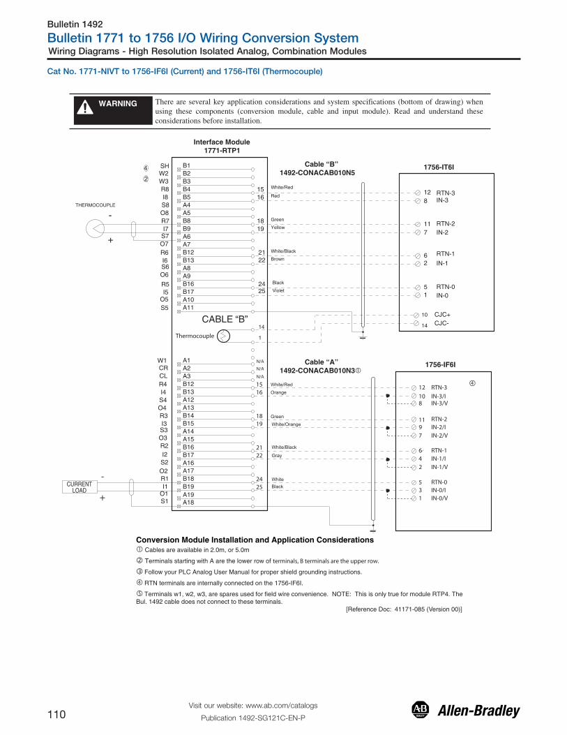
Conversion Module Installation and Application Considerations� Cables are available in 2.0m, or 5.0m
� Terminals starting with A are the lower row of terminals, B terminals are the upper row.
� Follow your PLC Analog User Manual for proper shield grounding instructions.
� RTN terminals are internally connected on the 1756-IF6I.
� Terminals w1, w2, w3, are spares used for field wire convenience. NOTE: This is only true for module RTP4. The Bul. 1492 cable does not connect to these terminals. [Reference Doc: 41171-085 (Version 00)]
Interface Module1771-RTP1
There are several key application considerations and system specifications (bottom of drawing) when using these components (conversion module, cable and input module). Read and understand these considerations before installation.
WARNING
Cable “A”1492-CONACAB010N3
Cable “B”1492-CONACAB010N5
�1756-IF6I
1756-IT6IB1B2B3B4B5A4A5B8B9A6A7B12B13A8A9B16B17A10A11
2W2SH
W3
I8
I7
I6
I5
I4
I3
I1
I2
R8
R7
R6
R5
R4
R3
R2
R1
4
A1A2A3B12B13A12A13B14B15A14A15B16B17A16A17B18B19
A18A19
CRW1
CL
O8
O7
O6
O5
O4
O3
O1
O2
S8
S7
S6
S5
S4
S3
S2
S1
CABLE “B”
1516
1918
2524
2122
+
-
Black
Red
Green
Brown
White/Black
White/Red
Yellow
Violet
THERMOCOUPLE
15
62
711
812
RTN-0
RTN-1
RTN-2
RTN-3
IN-0
IN-2
IN-3
IN-1
CJC+CJC-
Thermocouple
CURRENTLOAD
+
-
N/A
N/A
N/A
�1516
1819
2122
2425 3
5
46
119
10
12
BlackWhite
Green
Orange
White/Black
White/Red
White/Orange
Gray
IN-0/I
IN-1/I
IN-2/I
IN-3/I
RTN-0
RTN-2
RTN-3
RTN-1
1 IN-0/V
2 IN-1/V
7 IN-2/V
8 IN-3/V
10
1414
1
Cat No. 1771-NIVT to 1756-IF6I (Current) and 1756-IT6I (Thermocouple)
Wiring Diagrams - High Resolution Isolated Analog, Combination Modules
Visit our website: www.ab.com/catalogs
Publication 1492-SG121C-EN-P110
Bulletin 1492
Bulletin 1771 to 1756 I/O Wiring Conversion System

Publication 1492-SG121C-EN-P – June 2013Supercedes Publication 1492-SG121B-EN-P – June 2011 Copyright ©2013 Rockwell Automation, Inc. All Rights Reserved. Printed in USA.
Allen-Bradley, Rockwell Software, and ControlLogix are trademarks of Rockwell Automation, Inc.
Recommended