WA
LLS &
PILA
RS
123123
tech
o-b
loc.
com
Specifications per pallet Imperial Metric
Cubing20.44 ft2 1.90 m2
69.23 lin. ft 21.10 lin. m
Approx. Weight 1 684 lbs 764 kg
Minimum radius 7.5 ft 2.3 m
Number of rows 10
Coverage per row 2.04 ft2 0.19 m2
Linear coverage per row 6.92 lin. ft 2.11 lin. m
L2
HDL1
Unit dimensions in mm Units /palletA Height 3 9⁄16 90 20 units
Depth 9 13⁄16 250Length 1 11 1⁄4 285Length 2 9 5⁄8 245
B Height 3 9⁄16 90 20 unitsDepth 9 13⁄16 250
Length 1 14 3⁄8 365Length 2 12 13⁄16 325
C Height 3 9⁄16 90 20 unitsDepth 9 13⁄16 250
Length 1 15 15⁄16 405Length 2 14 3⁄8 365
sandlewood shale grey chestnut brown champlain grey onyx black
01 | Linear pattern 02 | Linear pattern90 mm & 180 mm
Patterns are for design inspiration only. The installer is responsible to calculate & purchase the correct amount of material.
Visit our werbsite for more patterns.
DESCRIPTION : Double-sided wall TEXTURE : Slate
BRANDON 90 mm
Brandon 90 mm
PALLET OVERVIEW
August 03, 2018
BRANDON 90 & 180
COMPATIBLE CAPSSee page 103 for product compatibility.
NOTESWhen building a double-sided wall one pallet will cover an average of 19.28 ft2.
See page 99 to 119 for more technical information.
B A
C C
A
B

WA
LLS
& P
ILA
RS
124124
tech
o-b
loc.
com
Specifications per pallet Imperial Metric
Cubing20.44 ft2 1.90 m2
34.61 lin. ft 10.55 lin. m
Approx. Weight 1 719 lbs 780 kg
Minimum radius 7.5 ft 2.3 m
Number of rows 5
Coverage per row 4.09 ft2 0.38 m2
Linear coverage per row 6.92 lin. ft 2.11 lin. m
L2
HDL1
Unit dimensions in mm Units /palletA Height 7 1⁄16 180 10 units
Depth 9 13⁄16 250Length 1 11 1⁄4 285Length 2 9 5⁄8 245
B Height 7 1⁄16 180 10 unitsDepth 9 13⁄16 250
Length 1 14 3⁄8 365Length 2 12 13⁄16 325
C Height 7 1⁄16 180 10 unitsDepth 9 13⁄16 250
Length 1 15 15⁄16 405Length 2 14 3⁄8 365
sandlewood shale grey chestnut brown champlain grey onyx black
01 | Linear pattern 02 | Linear pattern90 mm & 180 mm
Patterns are for design inspiration only. The installer is responsible to calculate & purchase the correct amount of material.
Visit our werbsite for more patterns.
DESCRIPTION : Double-sided wall TEXTURE : Slate
BRANDON 180 mm
Brandon 180 mm
PALLET OVERVIEW
August 03, 2018
BRANDON 90 & 180
COMPATIBLE CAPSSee page 103 for product compatibility.
NOTESWhen building a double-sided wall one pallet will cover an average of 19.28 ft2.
See page 99 to 119 for more technical information.
B A
C C
A
B

WA
LLS &
PILA
RS
125125
tech
o-b
loc.
com
PILLAR PALLET OVERVIEW
COMPATIBLE CAPSSee page 103 for product compatibility.
NOTESSee page 99 to 119 for more technical information.
sandlewood shale grey chestnut brown champlain grey onyx black
Specifications per pallet Imperial Metric
PIL
LAR
90
mm Cubing 40 units 40 units
Approx. Weight 1 625 lbs 737 kg
Number of rows 4
Pillar height 35 7⁄16" 900 mm
HDL
Unit dimensions in mm Units /palletA Height 3 9⁄16 90 40 units
Depth 9 13⁄16 250Length 14 3⁄16 360
Specifications per pallet Imperial Metric
PIL
LAR
180
mm Cubing 20 units 20 units
Approx. Weight 1 636 lbs 742 kg
Number of rows 2
Pillar height 35 7⁄16" 900 mm
HDL
Unit dimensions in mm Units /palletA Height 7 1⁄16 180 20 units
Depth 9 13⁄16 250Length 14 3⁄16 360
DESCRIPTION : Pillars TEXTURE : Slate
BRANDON 90 & 180 mm
Brandon 90 & 180 mm

WA
LLS
& P
ILA
RS
126126
tech
o-b
loc.
com
8
CASE N° 1 :No SurchargeNo BackslopeNo Toe Slope
CLEAN SAND/GRAVEL/ SAND AND GRAVEL MIXES (Ø=34°, = 120 pcf)GEOGRID: MIRAGRID 3XT BY TENCATE (RFd=1.10, RFcr=1.45, RFid=1.25, Cds=0.9, Ci=0.9)
1. The information contained in the design charts is supplied for information purposes only and as such should only be used for preliminarydesigns
2. The height (H) of the wall is the total height from the leveling pad to the top of the wall not including the thickness of the cap.3. = 34 120 pcf 34 120 pcf); foundation soil 34 20 pcf)4. A qualified engineer should be consulted for the final design to be used for construction.5. The foundation soil must be able to support the wall system. The bearing capacity of the foundation soil, settlement, and global stability
must be verified and validated by a qualified geotechnical engineer.6. The seismic analysis is not included7. The design charts do not apply to tiered walls.8. The charts assume that the walls are constructed in accordance with Techo-Bloc specifications, good construction practice and an
adequate drainage system9. The geogrid layout has been optimized to satisfy the design requirements of the NCMA's Design Manual for Segmental Retaining Walls,
3rd Edition.10. The minimum burial depth must be 6 in (150 mm) or 10% of the exposed height, whichever is greater.11. Engineering judgement should be used when interpolating between heights.12. Techo-Bloc and its predecessors, successors, beneficiaries, employees, associates, administrators and insurers accepts no liability for
the incorrect use of information contained in the design charts.13. For further information, please contact our technical service department.
DESIGN CHARTBRANDON 180 mm
(EQUIVALENT TO TWICE THE BRANDON 90 mm)SETBACK POSITION
2'-4"(0.72m)
4.4° 2'-11"(0.90m)
4.4°4'-2"
(1.26m)
4.4°
5'-4"(1.62m)
4.4°
7'-1"(2.16m)
4.4°8'-10"
(2.70m)
4.4°
6'-6" (1.98 m)
6'-6" (1.98 m)
6'-6" (1.98 m)
6'-6" (1.98 m)
6'-6" (1.98 m)
5'-6" (1.68 m)
5'-6" (1.68 m)
5'-6" (1.68 m)
5'-6" (1.68 m)4'-6" (1.37 m)
4'-6" (1.37 m)
4'-6" (1.37 m)
4'-0" (1.22 m)
4'-0" (1.22 m)4'-0" (1.22 m)
VISIT WWW.TECHO-BLOC.COM FOR COMPLETE DESIGN CHART DOCUMENT

WA
LLS &
PILA
RS
127127
tech
o-b
loc.
com
INSTALLATION GUIDE
1-Row Pattern | Laying Patterns
The 1-row pattern provides three different combinations. Each combination is 10.38’ (3.165 m) long and 7 1⁄16’’ (180 mm) high. This pattern can be used for installing the last row of modules or where other patterns cannot be used.
NUMBER OF BLOCKS REQUIRED MODULE
BRANDON A B C
67% of the surface - Brandon 90 mm 4 4 4
33% of the surface - Brandon 180 mm 1 1 1
RETAINING WALLS - BRANDON 90 & 180 mm

WA
LLS
& P
ILA
RS
128128
tech
o-b
loc.
com
INSTALLATION GUIDE
3-Row Pattern | Laying Patterns
The 3-row pattern is 10.38’ (3.165 m) long and 21 1⁄4’’ (540 mm) high. This pattern allows a continuous leveled surface every 21 1⁄4’’(540 mm), which corresponds to the recommended maximum spacing between the layers of geogrid in a Brandon wall. This pattern is recommended when using the geogrid.
NUMBER OF BLOCKS REQUIRED MODULE
BRANDON A B C
67% of the surface - Brandon 90 mm 12 12 12
33% of the surface - Brandon 180 mm 3 3 3
RETAINING WALLS - BRANDON 90 & 180 mm
WA
LLS &
PILA
RS
129129
tech
o-b
loc.
com
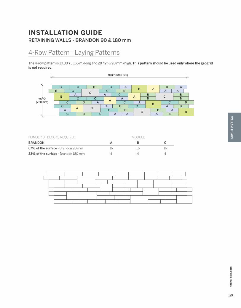
INSTALLATION GUIDE
4-Row Pattern | Laying Patterns
The 4-row pattern is 10.38’ (3.165 m) long and 28 3⁄8’’ (720 mm) high. This pattern should be used only where the geogrid is not required.
NUMBER OF BLOCKS REQUIRED MODULE
BRANDON A B C
67% of the surface - Brandon 90 mm 16 16 16
33% of the surface - Brandon 180 mm 4 4 4
RETAINING WALLS - BRANDON 90 & 180 mm

WA
LLS
& P
ILA
RS
130130
tech
o-b
loc.
com
INSTALLATION GUIDE
DOUBLE-SIDED WALL - END OF A STRAIGHT WALL
Module creation 1
Cut line Cut line
Module creation 2
Module creation 1
Module creation 1 Module creation 2
Module creation 1 Module creation 2
Module creation 4
Module creation 3
Module creation 5
Cut line Cut line
Cut line
Texturedsides
Texturedsides
Texturedsides
Texturedsides
Cut line
Regular block
Regular block
Regular block
Corner unit
Even row
Odd row
Even row
Odd row
Even row
Odd row
Even rowOdd row
Regular block
Corner block cut to reveal texture
Cut line Cut line
Cut line
Cut line
Cut line
Module creation 2
GENERAL NOTES
1. Alternate odd and even rows.
2. Stagger joints from one row to the next.
3. Glue all modules at each row with a concrete adhesive.
4. Cavities, grooves and connectors are not illustrated to avoid overloading the image.
90° CORNER OF A DOUBLE-SIDED WALL
Module creation 2
Module creation 2
Cut line
Cut lineEVEN ROW
ODD ROW
EVEN ROW
ODD ROW
Corner unit
Corner unit
Regular block
Regular block
Regular block
Regular block
Corner block cut to reveal texture
Corner block cut to reveal texture
Module creation 2
Module creation 2
Cut line
Cut lineEVEN ROW
ODD ROW
EVEN ROW
ODD ROW
Corner unit
Corner unit
Regular block
Regular block
Regular block
Regular block
Corner block cut to reveal texture
Corner block cut to reveal texture
1. Alternate odd and even rows.
2. Stagger joints from one row to the next.
3. Glue all modules at each row with a concrete adhesive.
4. Cavities, grooves and connectors are not illustrated to avoid overloading the image.
FREESTANDING WALLS - BRANDON 90 & 180 mm
BRANDON 90 mm & 180 mm
A. TECHO-BLOC CAP UNIT SECURED TO UNIT BELOW WITH CONCRETE ADHESIVE
B. BRANDON 90 mm AND 180 mm DOUBLE-SIDED WALL UNITS SECURE EACH ROW WITH CONCRETE ADHESIVE
C. CONNECTOR
D. EMBEDMENT DEPTH, 6” (150 mm) MIN.
E. 29 7⁄16’’ (750 mm) MAX.
F. GEOTEXTILE
G. COMPACTED GRANULAR LEVELING PAD, 6’’ (150 mm) THICK MIN. THICKNESS ACCORDING TO PROJECT SPECIFIC CONDITIONS

WA
LLS &
PILA
RS
131131
tech
o-b
loc.
com
INSTALLATION GUIDE DOUBLE-SIDED WALL RADIUS - BRANDON 90 & 180 mm
It is the user’s responsibility to verify for the quantity of materials required.
STEPS
BRANDON 90 mm
BRANDON 180 mm
For all possible combinations of pillars and caps, please refer to the correspondence table on page 103

WA
LLS
& P
ILA
RS
132132
tech
o-b
loc.
com
INSTALLATION GUIDE PILLARS - BRANDON 90 & 180 mm
A. PILLAR CAP UNIT, SECURE TO UNITS BELOW WITH A CONCRETE ADHESIVE
B. BRANDON 90 mm PILLAR UNIT SECURE EACH ROW WITH CONCRETE ADHESIVE
C. EMBEDMENT DEPTH: 150 mm (6") MIN.
D. 900 mm (35 7⁄16"), HEIGHT PER PALLET 1 080 mm (42 1⁄2"), MAXIMUM HEIGHT
E. GEOTEXTILE
F. COMPACTED GRANULAR BASE 150 mm (6") THICK MIN. THICKNESS ACCORDING TO PROJECT SPECIFIC CONDITIONS
BRANDON 90 mm
A. PILLAR CAP UNIT, SECURE TO UNITS BELOW WITH A CONCRETE ADHESIVE
B. BRANDON 180 mm PILLAR UNIT SECURE EACH ROW WITH CONCRETE ADHESIVE
C. EMBEDMENT DEPTH: 150 mm (6") MIN.
D. 900 mm (35 7⁄16"), HEIGHT PER PALLET 1 080 mm (42 1⁄2"), MAXIMUM HEIGHT
E. GEOTEXTILE
F. COMPACTED GRANULAR BASE 150 mm (6") THICK MIN. THICKNESS ACCORDING TO PROJECT SPECIFIC CONDITIONS
BRANDON 180 mm
For all possible combinations of pillars and caps, please refer to the correspondence table on page 103

WA
LLS &
PILA
RS
133133
tech
o-b
loc.
com
INSTALLATION GUIDE PILLARS - BRANDON 90 & 180 mm
BRANDON 90 mm & 180 mmOPTION A
A. PILLAR CAP UNIT, SECURE TO UNITS BELOW WITH A CONCRETE ADHESIVE
B. BRANDON 90 mm PILLAR UNIT SECURE EACH ROW WITH CONCRETE ADHESIVE
C. BRANDON 180 mm PILLAR UNIT SECURE EACH ROW WITH CONCRETE ADHESIVE
D. EMBEDMENT DEPTH: 150 mm (6") MIN.
E. 900 mm (35 7⁄16"), 1 080 mm (42 1⁄2"), MAXIMUM HEIGHT
F. GEOTEXTILE
G. COMPACTED GRANULAR BASE 150 mm (6") THICK MIN. THICKNESS ACCORDING TO PROJECT SPECIFIC CONDITIONS
BRANDON 90 mm & 180 mmOPTION B
For all possible combinations of pillars and caps, please refer to the correspondence table on page 103

WA
LLS
& P
ILA
RS
134134
tech
o-b
loc.
com
INSTALLATION GUIDE GRILL ISLAND - BRANDON 90 & 180 mm
ELEVATION A
ELEVATION B
ELEVATION D
ELEVATION C
A. YORK COUNTER TOP 24” × 36” × 2 1⁄4”
B. BRANDON 90 MM UNIT (A, B OR C) – LONG FACE EXPOSED (SHOWN WITH UPPERCASE LETTER)
C. BRANDON 90 MM UNIT (A, B OR C) – SHORT FACE EXPOSED (SHOWN WITH LOWERCASE LETTER)
D. BRANDON 180 MM UNIT (A, B OR C) – LONG FACE EXPOSED (SHOWN WITH UPPERCASE LETTER)
E. BRANDON 180 MM UNIT (A, B OR C) – SHORT FACE EXPOSED (SHOWN WITH LOWERCASE LETTER)
F. BRANDON 90 MM PILLAR UNIT
G. BRANDON 180 MM PILLAR UNIT
H. BRANDON UNIT CUT ON FIELD
I. CAST IN PLACE CONCRETE SLAB 4350 PSI (30 MPA), 5” (125 MM) THICK
J. 4X4-4/4 (102X102-MW25.8XMW25.8) WELDED WIRE MESH AND/OR REBAR AS PER SITE CONDITIONS
K. 12’’ (300 MM) DIA. CONCRETE PILLAR, AS PER LOCAL CODE
L. 3/4” (20 MM) CLEAN STONE 6” (150 MM) THICK MIN. AS PER SITE CONDITIONS
M. NATURAL SOIL OR COMPACTED BACKFILL
N. GEOTEXTILE
QUANTITY OF MATERIALS REQUIRED
- York Counter top 24” × 36” × 2 1⁄4”: 4
- Brandon 90 mm unit: 20 A , 20 B , 18 C
- Brandon 180 mm unit: 10 A , 10 B , 9 C
- Brandon 90 mm Pillar unit: 18
- Brandon 180 mm Pillar unit: 15
NOTE: Appliances and utilities may vary for each project and are not shown on this drawing. This drawing is shown for inspiration only and surplus or shortage of materials may result. It is the user’s responsibility to verify for the quantity of materials required. Secure the blocks using a heat resistant concrete adhesive. The installer must ensure that the installation and use of the grill island comply with local regulations and code requirements. Concrete pillars extending to frost line may be required as per local code. Check your local building code before installing.
TOP VIEW

WA
LLS &
PILA
RS
135135
tech
o-b
loc.
com
INSTALLATION GUIDE PIZZA OVEN - BRANDON 90 & 180 mm
A A A
A
A
A
A
A
A
A
A
A
A
A A AC
A
AA
A
AA
C
±1014 mm(40'')
180 mm7 1
16''
±1219 mm
±720 mm
57 mm
±914 mm
90 mm
A
BD
C
± 1219 mm
± 914 mm(3' 0'')
± 122 mm
± 97 mm
180 mm7 1
16''
±970 mm250 mm
E G
BGB
B
E
B
G F BB
IE B H
B
I
B
B
B B HB
IB B
H B B
IB B
B
H B EB I
BB
B
B I
GF
D
D D D
D D D D D D
D D D
(4'-0'')
(3 78'')
(4 78'')
(4'-0'')
(38 316'')
±1014 mm(40'')
(28 38'')
57 mm(2 1
4'')
(9 1316'')
(2 14'')
(3 916'')
(3' 0'')
(1' 6 12'')
±720 mm2' 4 3 8''
±970 mm(38 3
16'')±720 mm
(28 38'')
±470 mm
JJ J
J
D
D
D D
D
DD
A.BRANDON 180 mm PILLAR UNIT: 7 116'' x 9 13
16'' x 14 316''
(180 x 250 x 360 mm) 16 U.
B.BRANDON 90 mm PILLAR UNIT: 3 916'' x 9 13
16'' x 14 316''
(90 x 250 x 360 mm) 16 U.
C.BRANDON 180 mm PILLAR UNIT: (CUT ON FIELD)
7 116'' x 9 13
16'' x 4 516''
(180 x 250 x 110 mm) 2 U.
D.CAP PIEDIMONTE 12X30:(CUT ON FIELD)
2 14'' x 11 34'' x 24''
(57 x 298 x 610 mm) 12 U.
E.BRANDON 90 mm PILLAR UNIT :(CUT ON FIELD)
3 916'' x 9 13
16'' x 11''(90 x 250 x 279 mm)
2 U.
F.BRANDON 90 mm PILLAR UNIT :(CUT ON FIELD)
3 916'' x 9 13
16'' x 9''(90 x 250 x 229 mm)
2 U.
G.BRANDON 90 mm PILLAR UNIT :(CUT ON FIELD)
3 916'' x 9 13
16'' x 9 12''(90 x 250 x 241 mm)
2 U.
H.BRANDON 90 mm PILLAR UNIT :(CUT ON FIELD)
3 916'' x 9 13
16'' x 3 316''
(90 x 250 x 81 mm) 2 U.
I. BRANDON 90 mm PILLAR UNIT :(CUT ON FIELD)
3 916'' x 9 13
16'' x 4 516''
(90 x 250 x 110 mm) 6 U.
J.FORNO APPLIANCE: 1 U.
NOTE : Secure the blocks using a heat resistant concrete adhesive. The installer must ensure that the installation and use of the pizza oven comply with local regulations and code requirements. The construction of the base should include the installation of a concrete slab and pillars under the slab. The depth of the pillars and reinforcement requirements should be determined based on site conditions and comply with local code.
PLAN VIEW ELEVATION A
ELEVATION B ELEVATION C ELEVATION D
CUT-IN PLACE BLOCK
Recommended