BR 6/00 1
Universal Serial Bus
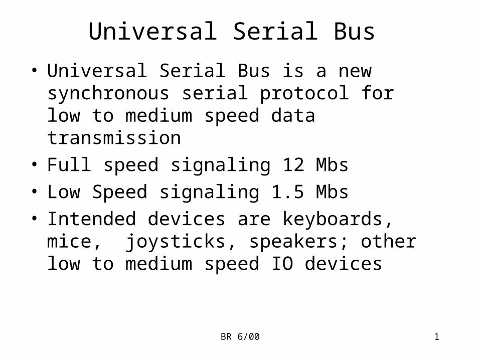
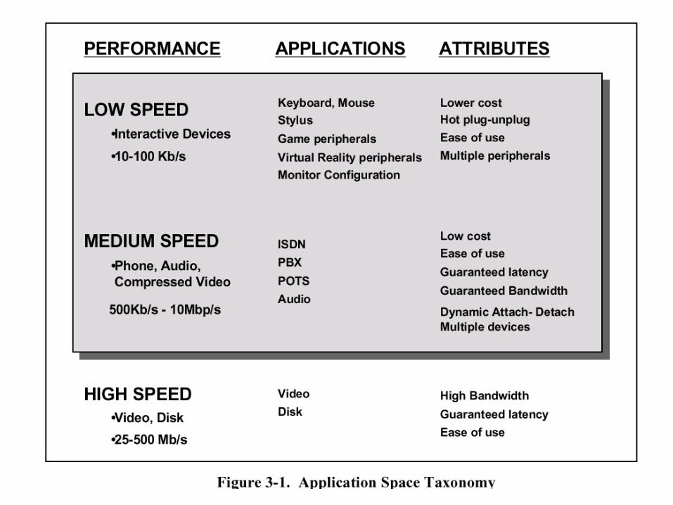
• Universal Serial Bus is a new synchronous serial protocol for low to medium speed data transmission
• Full speed signaling 12 Mbs • Low Speed signaling 1.5 Mbs• Intended devices are keyboards, mice, joysticks,
speakers; other low to medium speed IO devices
BR 6/00 2
BR 6/00 3
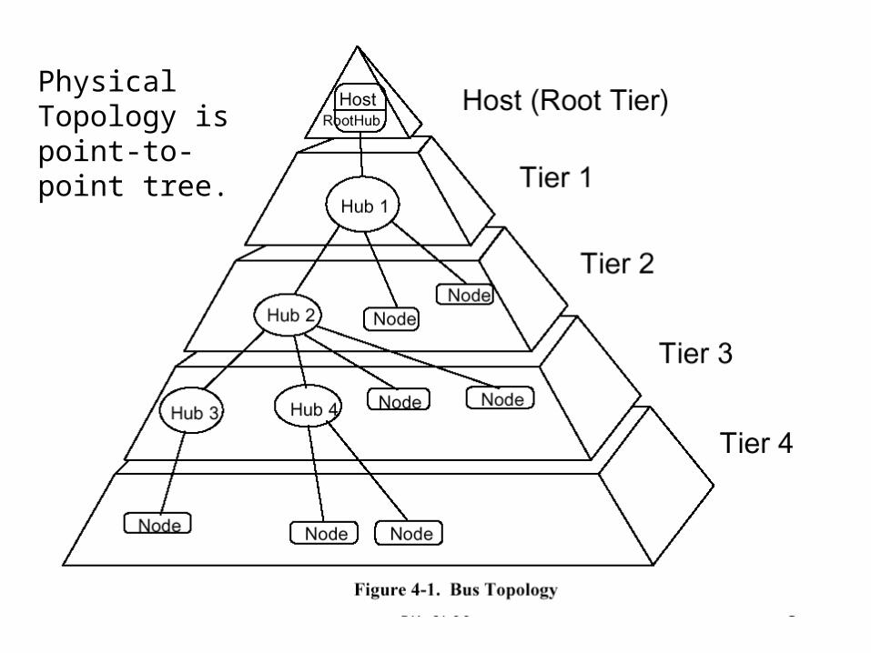
Physical Topology is point-to-point tree.
BR 6/00 4
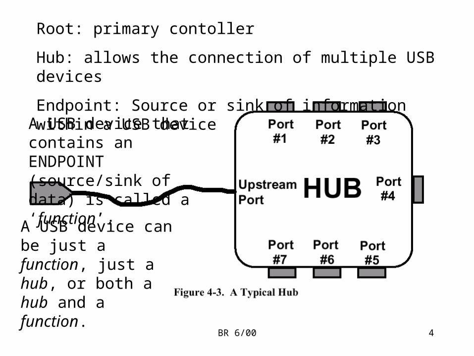
Root: primary contoller
Hub: allows the connection of multiple USB devices
Endpoint: Source or sink of information within a USB device
A USB device that contains an ENDPOINT (source/sink of data) is called a ‘function’.
A USB device can be just a function, just a hub, or both a hub and a function.
BR 6/00 5
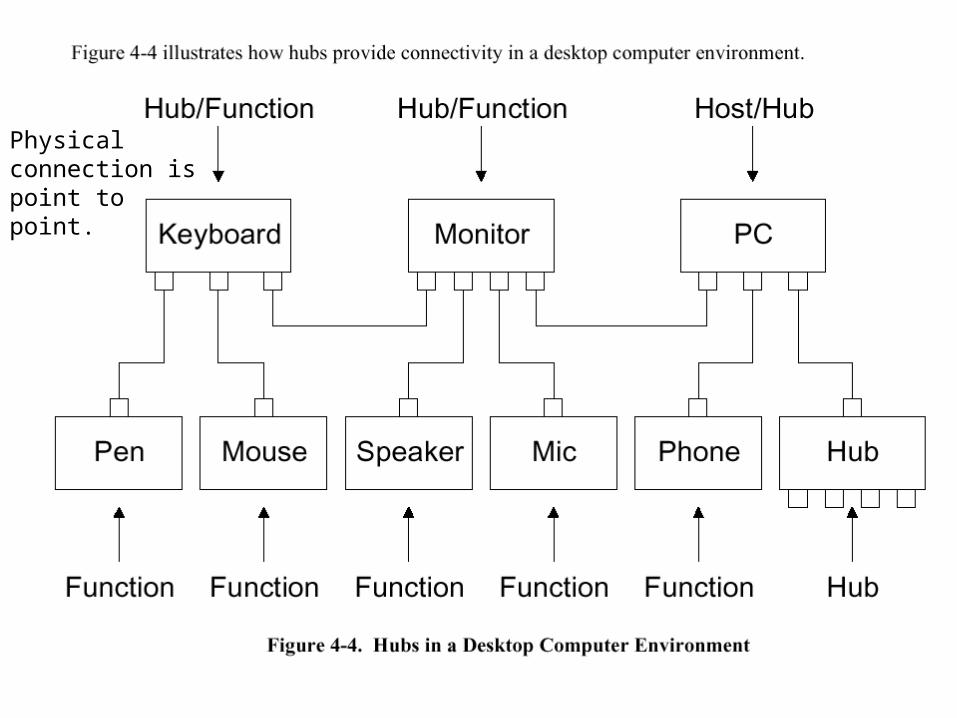
Physical connection is point to point.
BR 6/00 6
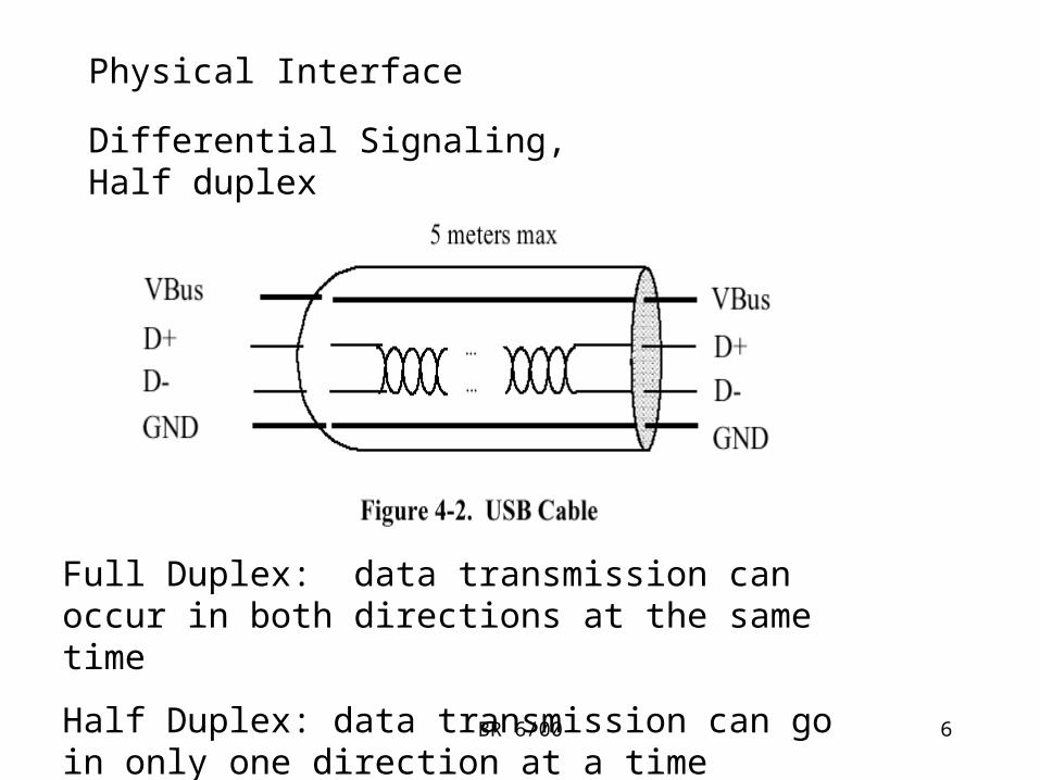
Physical Interface
Differential Signaling, Half duplex
Full Duplex: data transmission can occur in both directions at the same time
Half Duplex: data transmission can go in only one direction at a time
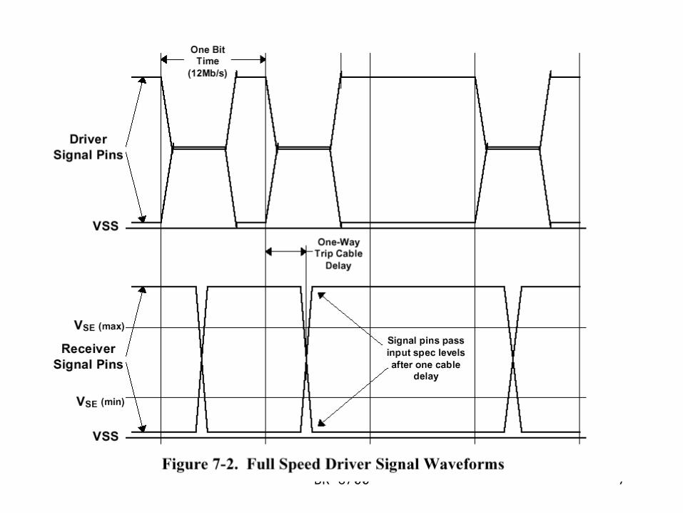
BR 6/00 7
BR 6/00 8
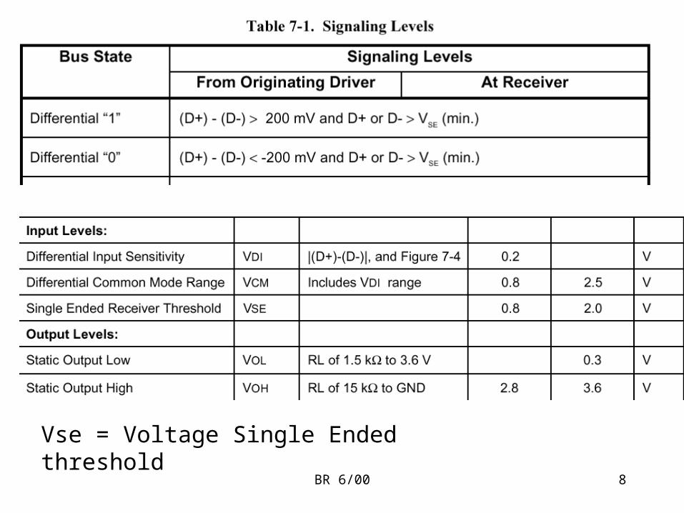
Vse = Voltage Single Ended threshold
BR 6/00 9
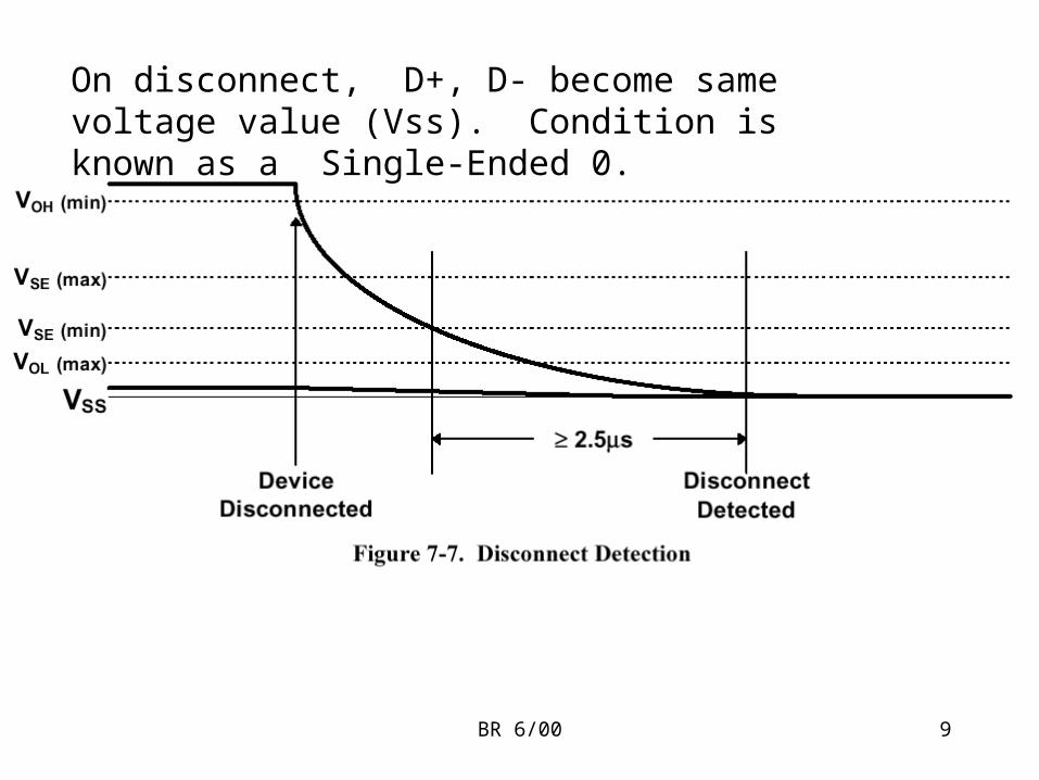
On disconnect, D+, D- become same voltage value (Vss). Condition is known as a Single-Ended 0.
BR 6/00 10
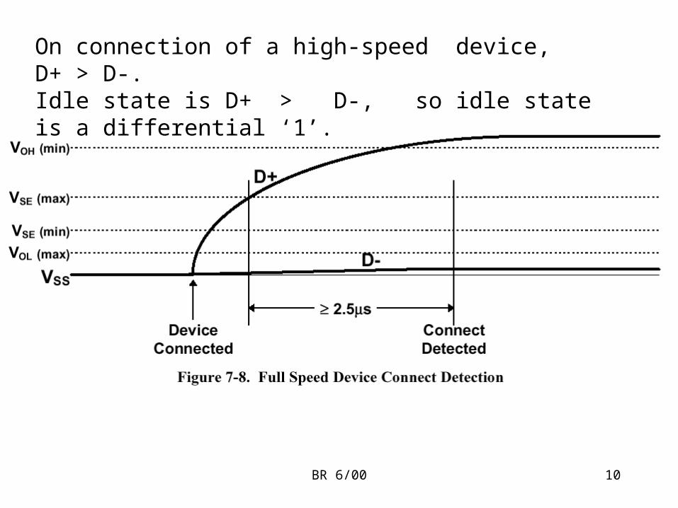
On connection of a high-speed device, D+ > D-.Idle state is D+ > D-, so idle state is a differential ‘1’.
BR 6/00 11
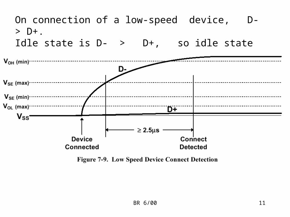
On connection of a low-speed device, D- > D+.Idle state is D- > D+, so idle state is a differential ‘0’.
BR 6/00 12
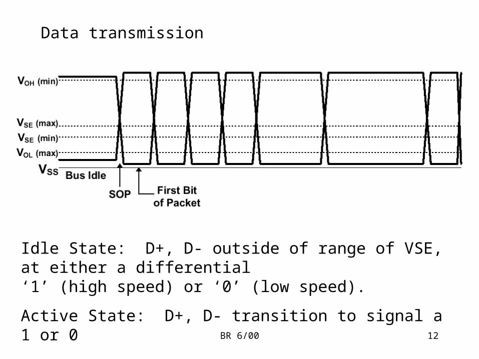
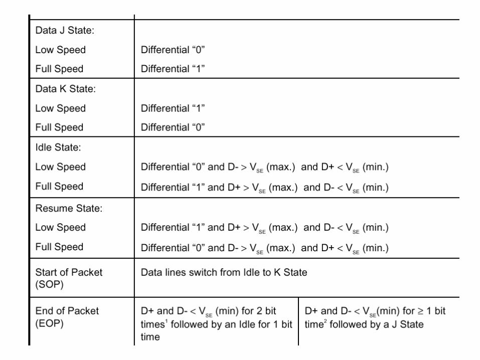
Idle State: D+, D- outside of range of VSE, at either a differential‘1’ (high speed) or ‘0’ (low speed).
Active State: D+, D- transition to signal a 1 or 0
Data transmission
BR 6/00 13
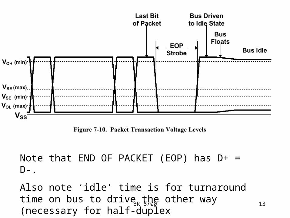
Note that END OF PACKET (EOP) has D+ = D-.
Also note ‘idle’ time is for turnaround time on bus to drive the other way (necessary for half-duplex communication).
BR 6/00 14
BR 6/00 15
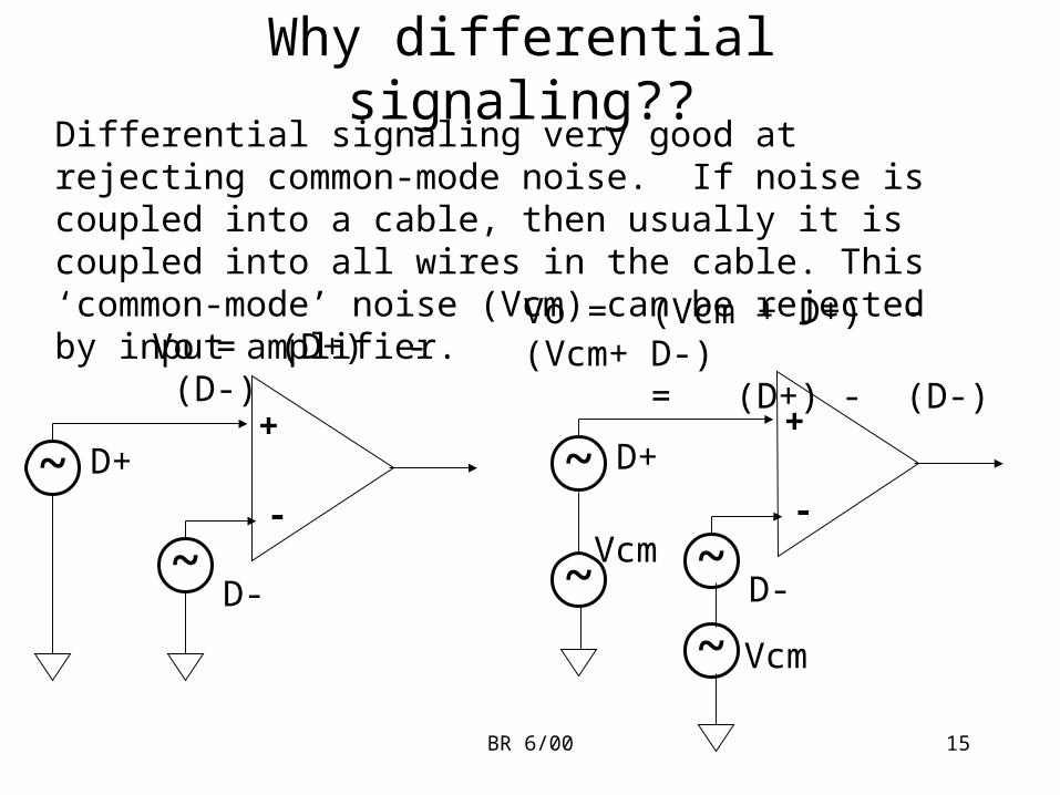
Why differential signaling??Differential signaling very good at rejecting common-mode noise. If noise is coupled into a cable, then usually it is coupled into all wires in the cable. This ‘common-mode’ noise (Vcm) can be rejected by input amplifier.
+
-~ D+
~D-
Vo = (D+) - (D-)
+
-~ D+
~D-~
Vcm
~ Vcm
Vo = (Vcm + D+) - (Vcm+ D-) = (D+) - (D-)
BR 6/00 16
NRZ
NRZI
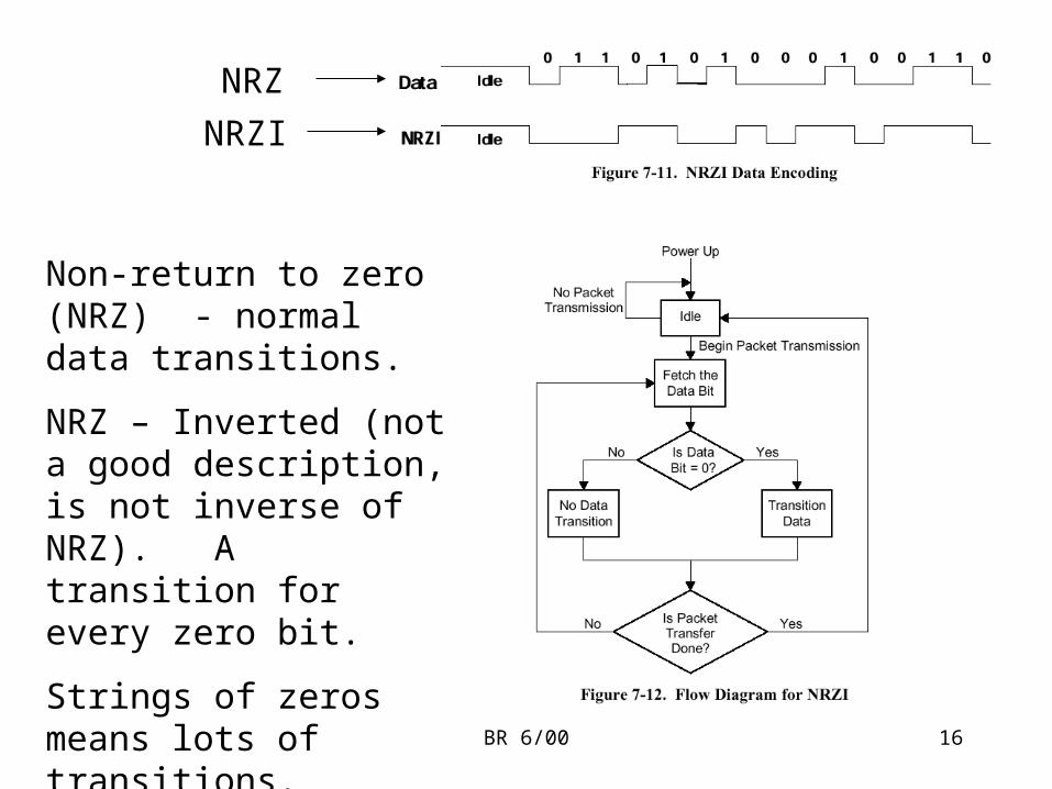
Non-return to zero (NRZ) - normal data transitions.
NRZ – Inverted (not a good description, is not inverse of NRZ). A transition for every zero bit.
Strings of zeros means lots of transitions. Strings of ‘1’s means steady line.
BR 6/00 17
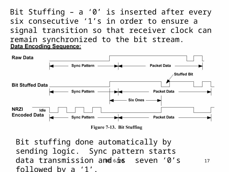
Bit Stuffing – a ‘0’ is inserted after every six consecutive ‘1’s in order to ensure a signal transition so that receiver clock can remain synchronized to the bit stream.
Bit stuffing done automatically by sending logic. Sync pattern starts data transmission and is seven ‘0’s followed by a ‘1’.
BR 6/00 18
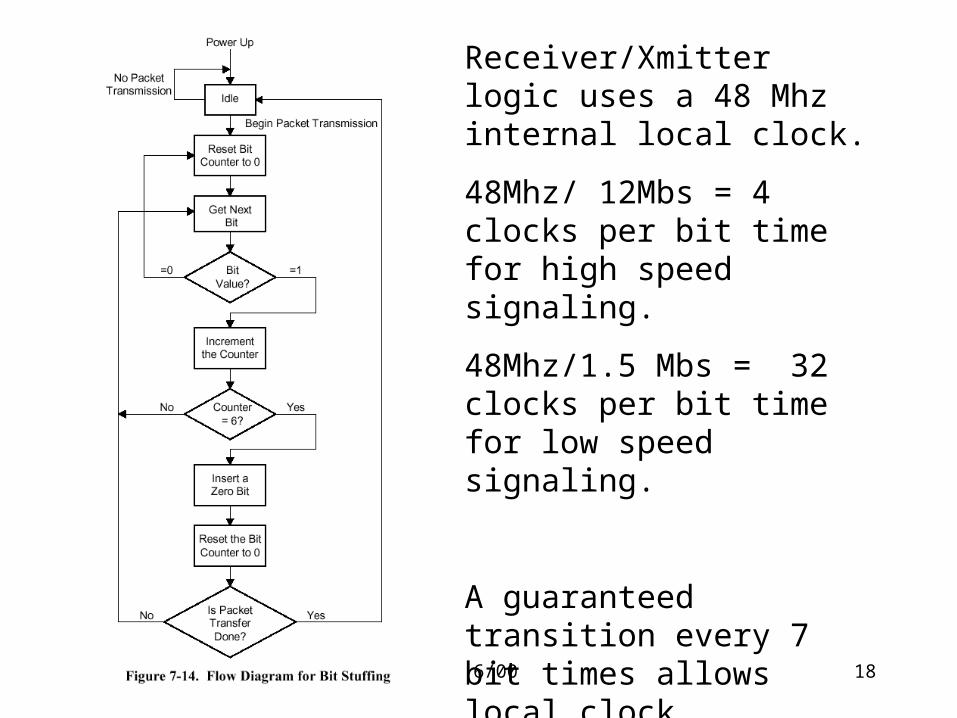
Receiver/Xmitter logic uses a 48 Mhz internal local clock.
48Mhz/ 12Mbs = 4 clocks per bit time for high speed signaling.
48Mhz/1.5 Mbs = 32 clocks per bit time for low speed signaling.
A guaranteed transition every 7 bit times allows local clock synchronization to the serial data stream. Sync pattern allows clock sync at beginning of packet.
BR 6/00 19
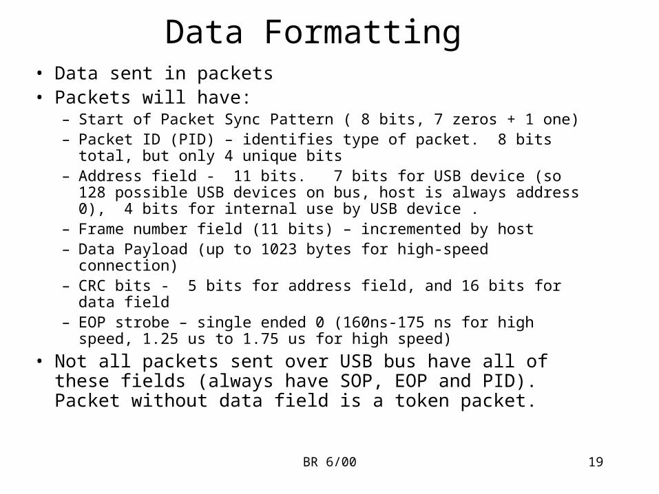
Data Formatting• Data sent in packets• Packets will have:
– Start of Packet Sync Pattern ( 8 bits, 7 zeros + 1 one)– Packet ID (PID) – identifies type of packet. 8 bits total, but only 4
unique bits – Address field - 11 bits. 7 bits for USB device (so 128 possible USB
devices on bus, host is always address 0), 4 bits for internal use by USB device .
– Frame number field (11 bits) – incremented by host– Data Payload (up to 1023 bytes for high-speed connection)– CRC bits - 5 bits for address field, and 16 bits for data field– EOP strobe – single ended 0 (160ns-175 ns for high speed, 1.25 us to
1.75 us for high speed)
• Not all packets sent over USB bus have all of these fields (always have SOP, EOP and PID). Packet without data field is a token packet.
BR 6/00 20
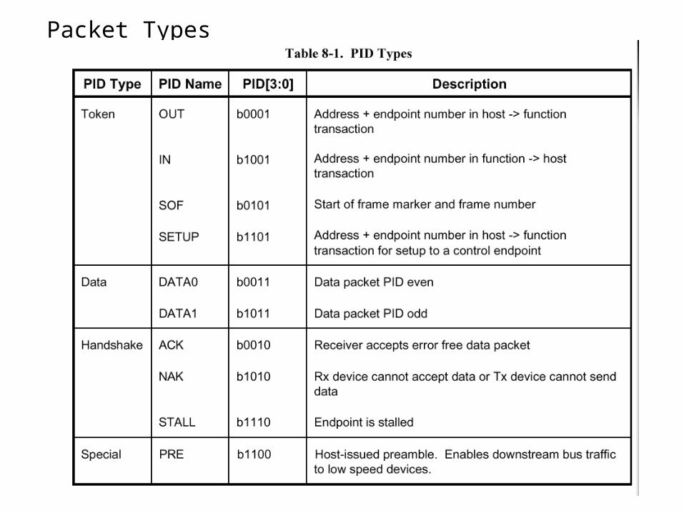
Packet Types
BR 6/00 21
BR 6/00 22
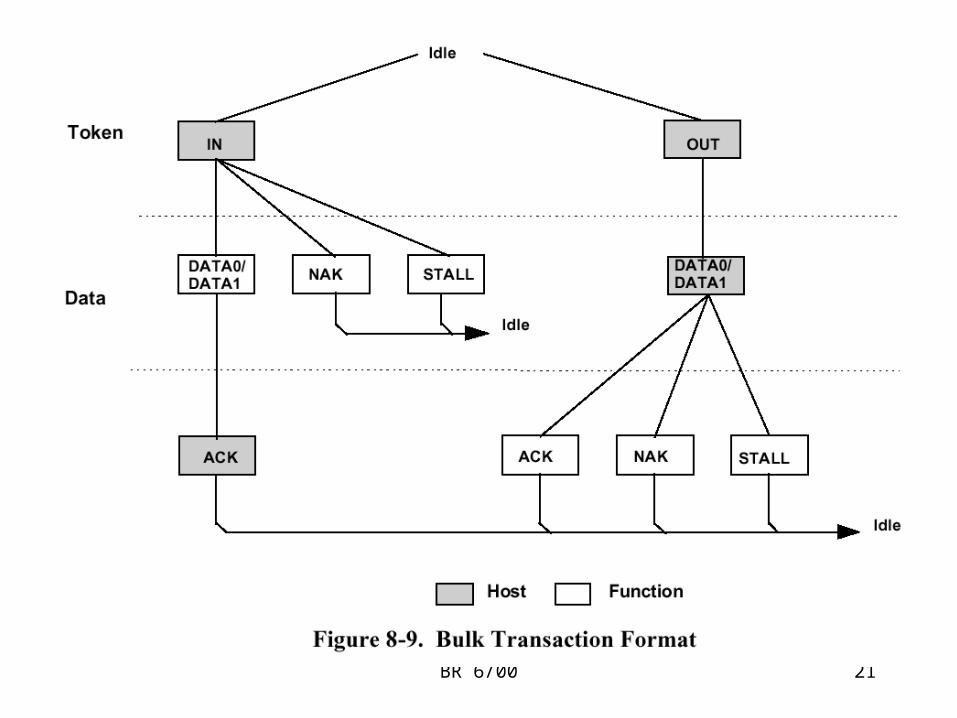
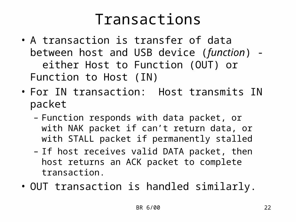
Transactions• A transaction is transfer of data between host and
USB device (function) - either Host to Function (OUT) or Function to Host (IN)
• For IN transaction: Host transmits IN packet– Function responds with data packet, or with NAK
packet if can’t return data, or with STALL packet if permanently stalled
– If host receives valid DATA packet, then host returns an ACK packet to complete transaction.
• OUT transaction is handled similarly.
BR 6/00 23
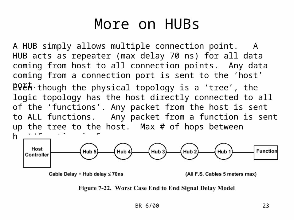
More on HUBsA HUB simply allows multiple connection point. A HUB acts as repeater (max delay 70 ns) for all data coming from host to all connection points. Any data coming from a connection port is sent to the ‘host’ port.
Even though the physical topology is a ‘tree’, the logic topology has the host directly connected to all of the ‘functions’. Any packet from the host is sent to ALL functions. Any packet from a function is sent up the tree to the host. Max # of hops between host/function is 5.
BR 6/00 24
Supported Data Transfer types
• Control Transfers – used to configure devices at power up
• Bulk Transfers – large amounts of data transferred sequentially (i.e., printers, scanners)
• Interrupt transfers – small, spontaneous data transfer from devices (mouse, keyboard, joystick). Interrupt transfers are scheduled transfers.
• Isochronous Transfers – continuous, real-time data. Guaranteed bandwidth; data is sensitive to delivery delays. Examples are audio, low-bandwidth video. Only used by full speed devices.
BR 6/00 25
Frames• Frames are the way that the bandwidth of the USB bus
is allocated among the different devices that are connected to the USB
• A Frame is a 1.0 ms period whose time is divided up among the various connected USB devices by the host.
• Start-of-Frame packets are sent over bus every 1.0 ms so that high-speed devices can keep a 1 Khz clock that is synchronized to the host 1 Khz clock
• An example of dividing up the frame bandwidth is that any device that needs interrupt transfers is allocated a period within the frame– Host accesses the endpoint and checks to see if it has
pending interrupt data. If data ready, grabs the data in the next frame.
BR 6/00 26
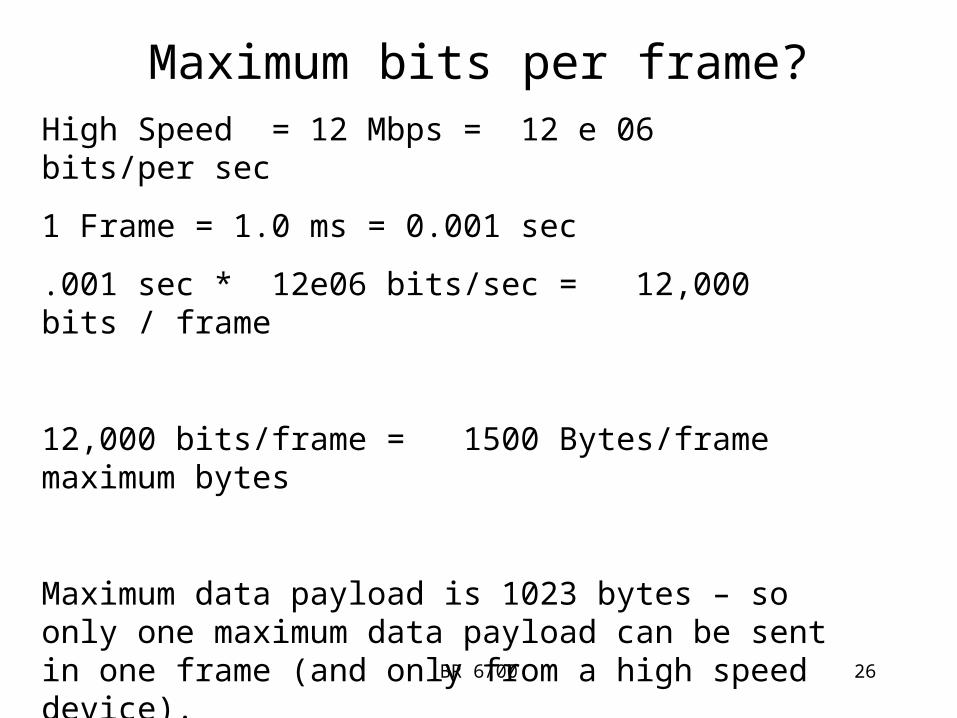
Maximum bits per frame?High Speed = 12 Mbps = 12 e 06 bits/per sec
1 Frame = 1.0 ms = 0.001 sec
.001 sec * 12e06 bits/sec = 12,000 bits / frame
12,000 bits/frame = 1500 Bytes/frame maximum bytes
Maximum data payload is 1023 bytes – so only one maximum data payload can be sent in one frame (and only from a high speed device).
BR 6/00 27
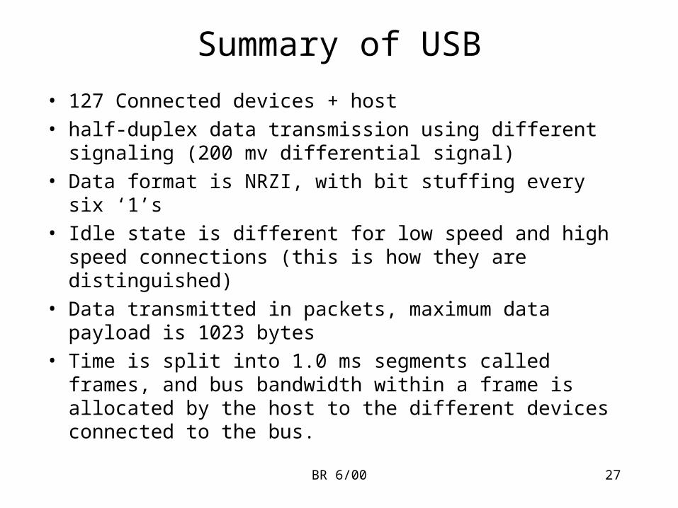
Summary of USB
• 127 Connected devices + host
• half-duplex data transmission using different signaling (200 mv differential signal)
• Data format is NRZI, with bit stuffing every six ‘1’s
• Idle state is different for low speed and high speed connections (this is how they are distinguished)
• Data transmitted in packets, maximum data payload is 1023 bytes
• Time is split into 1.0 ms segments called frames, and bus bandwidth within a frame is allocated by the host to the different devices connected to the bus.
BR 6/00 28
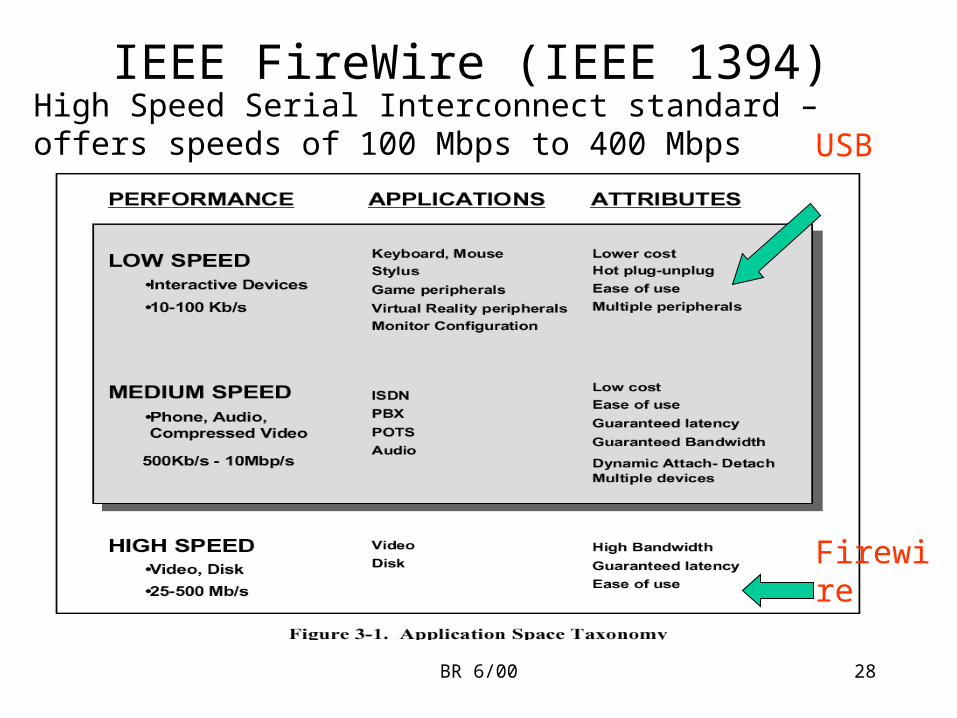
IEEE FireWire (IEEE 1394)High Speed Serial Interconnect standard – offers speeds of 100 Mbps to 400 Mbps USB
Firewire
BR 6/00 29
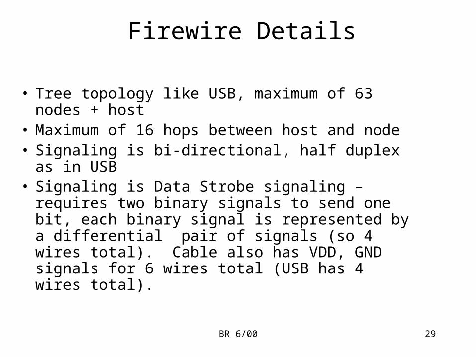
Firewire Details
• Tree topology like USB, maximum of 63 nodes + host
• Maximum of 16 hops between host and node• Signaling is bi-directional, half duplex as in USB• Signaling is Data Strobe signaling – requires two
binary signals to send one bit, each binary signal is represented by a differential pair of signals (so 4 wires total). Cable also has VDD, GND signals for 6 wires total (USB has 4 wires total).
BR 6/00 30
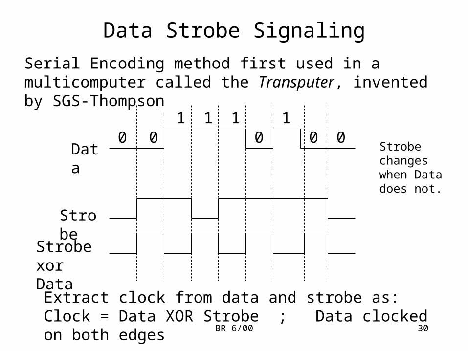
Data Strobe Signaling
Serial Encoding method first used in a multicomputer called the Transputer, invented by SGS-Thompson
0 01 1 1
Strobe
Data0 0 0
1
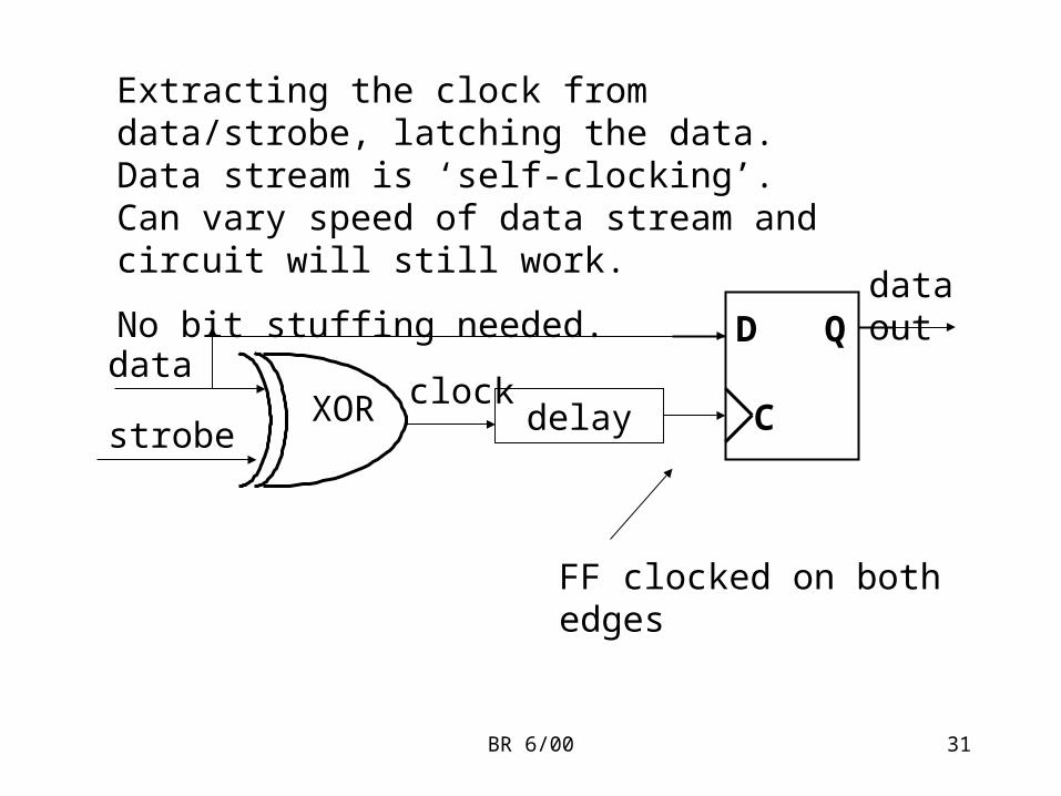
Extract clock from data and strobe as:Clock = Data XOR Strobe ; Data clocked on both edges
Strobe changes when Data does not.
Strobe xor Data
BR 6/00 31
XORdata
strobeclock
D Q
C
FF clocked on both edges
delay
Extracting the clock from data/strobe, latching the data. Data stream is ‘self-clocking’. Can vary speed of data stream and circuit will still work.
No bit stuffing needed.data out
BR 6/00 32
Cabling, Electrical Specs
• Cabling uses three pairs:– one pair for Vdd/GND
– one pair for Data (differential Signaling)
– one pair for Strobe (differential Signaling)
• 200 mV differential on Data (D+, D-), Strobe (S+, S-) centered about Vdd/2
• Cabling can provide power to nodes same as in USB spec.
Recommended