Blower Door Measurement – Air-Tightness Testing in Passive Houses
S. Dorschky1 and S. Rolfsmeier2
1 BlowerDoor GmbH, 2 IngBEU Ingenieurgemeinschaft Bau+Energie+Umwelt GmbH, Energie- und Umweltzentrum, D-
31832 Springe-Eldagsen, Germany ABSTRACT Air leakages can cause a significant energy penalty, inability of the heating system, and failure of the ventilation system – especially in passive houses. However, they can be avoided if given serious consideration in the design phase. The use of adequate materials and techniques as well as quality assurance during construction also have a positive impact on preventing air leakages. Air-tightness is the prerequisite for high-quality indoor air provided by a well-functioning ventilation system, for preventing harmful substances from being admitted, for a high comfort factor thanks to the prevention of draughts and cold air pockets, and for allowing the passive house concept to function properly. For these reasons, proof of tightness is required: n50,max = 0.6 h-1 [PHI-CEPHEUS 99]. KEYWORDS EN 13829, preliminary test, quality assurance, compressibility of air, air flow measurement HOW TO GET AN EXTREMELY AIRTIGHT ENVELOPE IN PASSIVE HOUSES?
Figure 1: To design the air barrier, draw a red line all along the inside of the envelope and draft
detailed plans for the circled connections.

Even in modern construction, air-tightness cannot be taken for granted since it requires special knowledge and skills from everybody involved in the construction process. Design, specifications, and coordination between the different trades are critical for success. Only when penetrations are minimized, connections simplified, and processes precisely specified can the project be reliable and enduring.
- First, plan the air barrier for all structural components of the house. Draw an uninterrupted red line along the inside of the building’s structural components.
- Avoid all unnecessary penetrations. Service entries should penetrate the air barrier only once, with a maximum of 15 penetrations.
- Devise a detailed plan of materials and methods to be used at all gasket joints and penetrations to make sure that the craftsmen can comply.
HOW TO RECORD THE MEASUREMENT VALUES / CARRY OUT THE STANDARD TEST? For about 20 years now, we have been able to measure air-tightness. In many countries, the BlowerDoor assembly has become an accepted device for performing envelope permeability measurements. The fan pressurization method is described in the European standard [EN 13829]. Air-tightness specifications have been defined in national codes and equally apply to passive houses. When performing an air-tightness measurement in a very tight building, the following factors should be taken into account: Measured extent (EN 13829, 5.1.2), internal volume (6.1.1) In each passive house, the insulated airtight envelope has been clearly defined. There is, for instance, no cellar staircase that would be heated unintentionally; there are no cock lofts or aisles where the air barrier is separate from the insulation level, and so forth. For measuring, take the air volume that was calculated for ventilation planning. Time of measurement (5.1.3) At least two tests should be commissioned, with the target value being specified in the building contract. First, the preliminary air permeability measurement For purposes of quality assurance, testing during an early stage of construction allows for a cost-effective removal of leakages. Many contractors carry out those preliminary air permeability measurements themselves. Quality assurance is important during the construction of the air barrier. Hence, it makes sense to use the blower door very early in the construction phase and to check air-tightness – together with the construction manager and contractors – at a depressurization of -50 Pa and to make improvements if necessary. For structures with an external air barrier, the
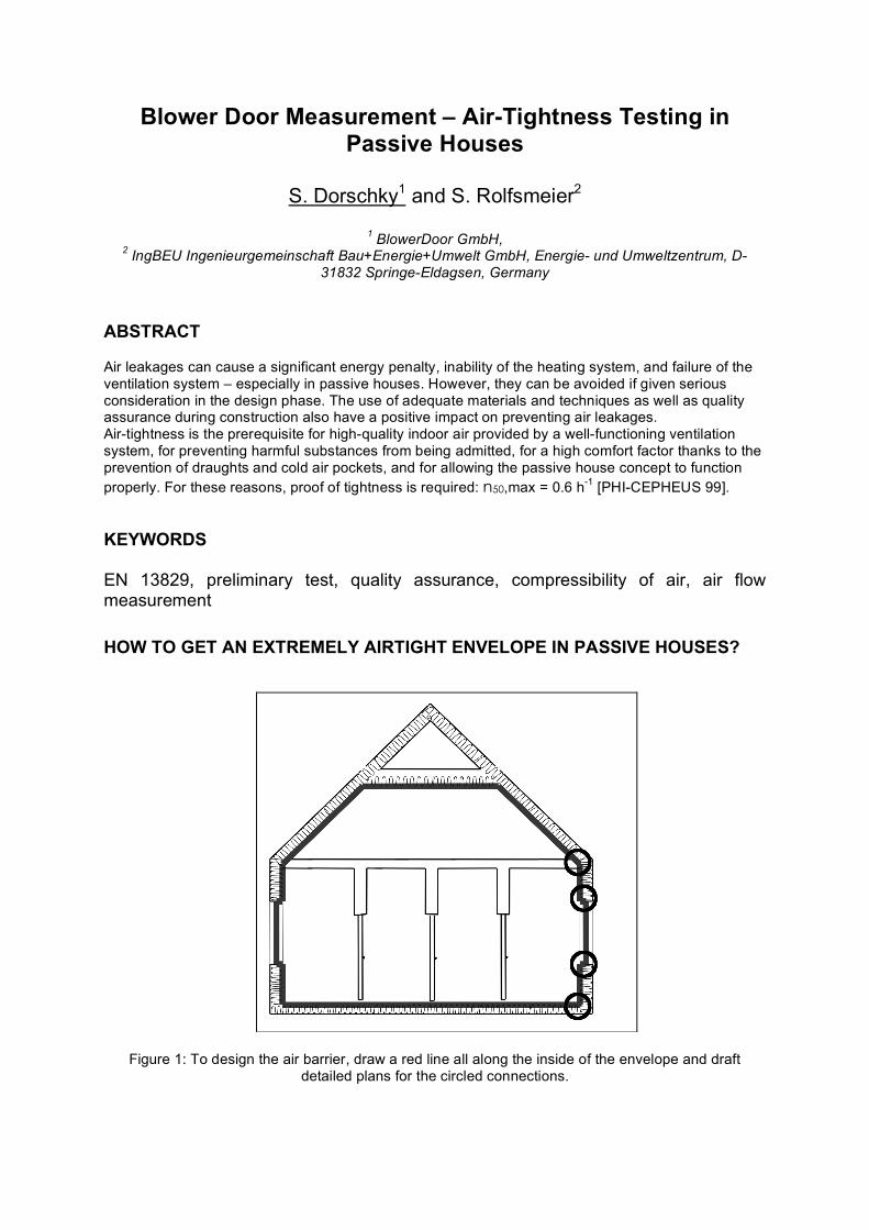
quality check is carried out in a pressurization test at +50 Pa. For large buildings, several fans are used [2]. The use of smoke at specific locations helps to identify leakage paths and illustrates where details of the air-tightness concept have to be optimized. For such a preliminary test it is not necessary to perform a complete measurement in accordance with EN 13829. In order to evaluate the quality of the air barrier at this stage of construction it is sufficient to read the air flow rate at 50 Pa pressure difference and to determine n50 with the help of internal volume (“one-point test @50Pa“).
Figure 2: Ideal construction stage for the preliminary air permeability measurement: the air barrier is visible (polyethylene, OSB, concrete)
Figure 3: Leaking passive house front door, demonstrated with fog at 50 Pa depressurization If the passive house concept is new to those involved in the construction process or if they have little experience with it, it is advisable to carry out several preliminary tests during the various construction phases and upon completion of the works to ensure acceptable results from all the trades. With more experience, certain construction phases may also be checked visually. Second, the measurement according to EN 13829 The final measurement to determine air permeability can only take place after the building envelope has been completed. In order to verify whether the passive house standard has been achieved this EN 13829 test should be carried out upon completion of all the works. PREPARATION (5.2) The final measurement should be carried out according to Method A (“test of a building in use”). Under that method, there must be no sealing except on the ventilation system. The position of those sealings is essential: if possible, pipes should be sealed at their point of passage through the envelope. An alternative would be the sealing of exhaust and supply air penetrations from the outside. Another
proven method is the insertion of ball bladder directly in the central unit after removal of the filters. If, however, all supply and exhaust air penetrations in all the rooms were sealed individually, the test pressure would be measured on all tube walls, deteriorating the results because of the air leakage rate over those many square meters of tube surface. (Of course the ventilation system should also be tight, but that is not a matter to be discussed in this paper.) When measuring the air-tightness of a building, for instance of a passive house, the BlowerDoor should not be installed at the door where the biggest leakage occurs. Since front doors very often constitute the weak point in terms of building tightness, a patio door should be chosen for installing the BlowerDoor. If only the front door (which often is leaky, see figure 3) can be used you should be careful in interpreting the results. ZERO-FLOW-PRESSURE DIFFERENCE (5.3.3) AND PRESSURE DIFFERENCE SEQUENCE (5.3.4)
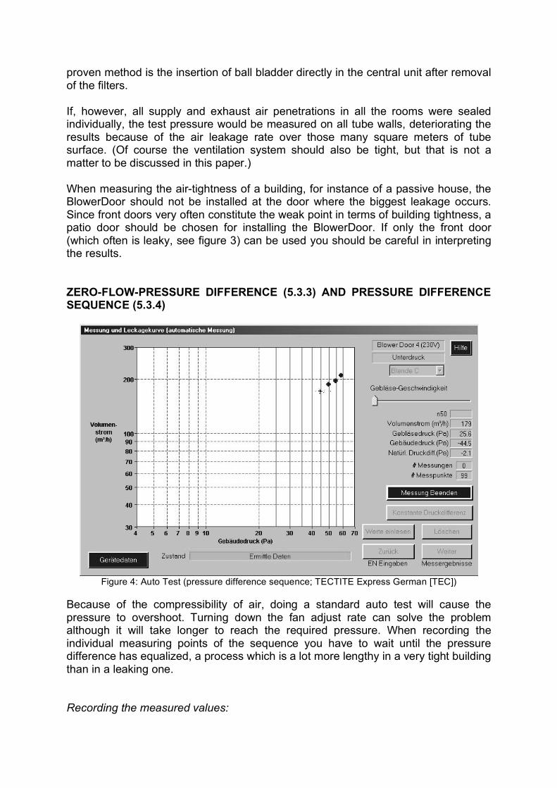
Figure 4: Auto Test (pressure difference sequence; TECTITE Express German [TEC])
Because of the compressibility of air, doing a standard auto test will cause the pressure to overshoot. Turning down the fan adjust rate can solve the problem although it will take longer to reach the required pressure. When recording the individual measuring points of the sequence you have to wait until the pressure difference has equalized, a process which is a lot more lengthy in a very tight building than in a leaking one. Recording the measured values:
Natural pressure difference before the measuring: a few minutes after having closed all doors, windows, and the fan; Each individual point of the measuring sequence: once the equilibrium pressure has been reached, i.e. after a few minutes; Natural pressure difference after the measuring: after the applied differential pressure has subsided. After turning off the fan, you can feel the air coming back in through the BlowerDoor fan for several seconds.
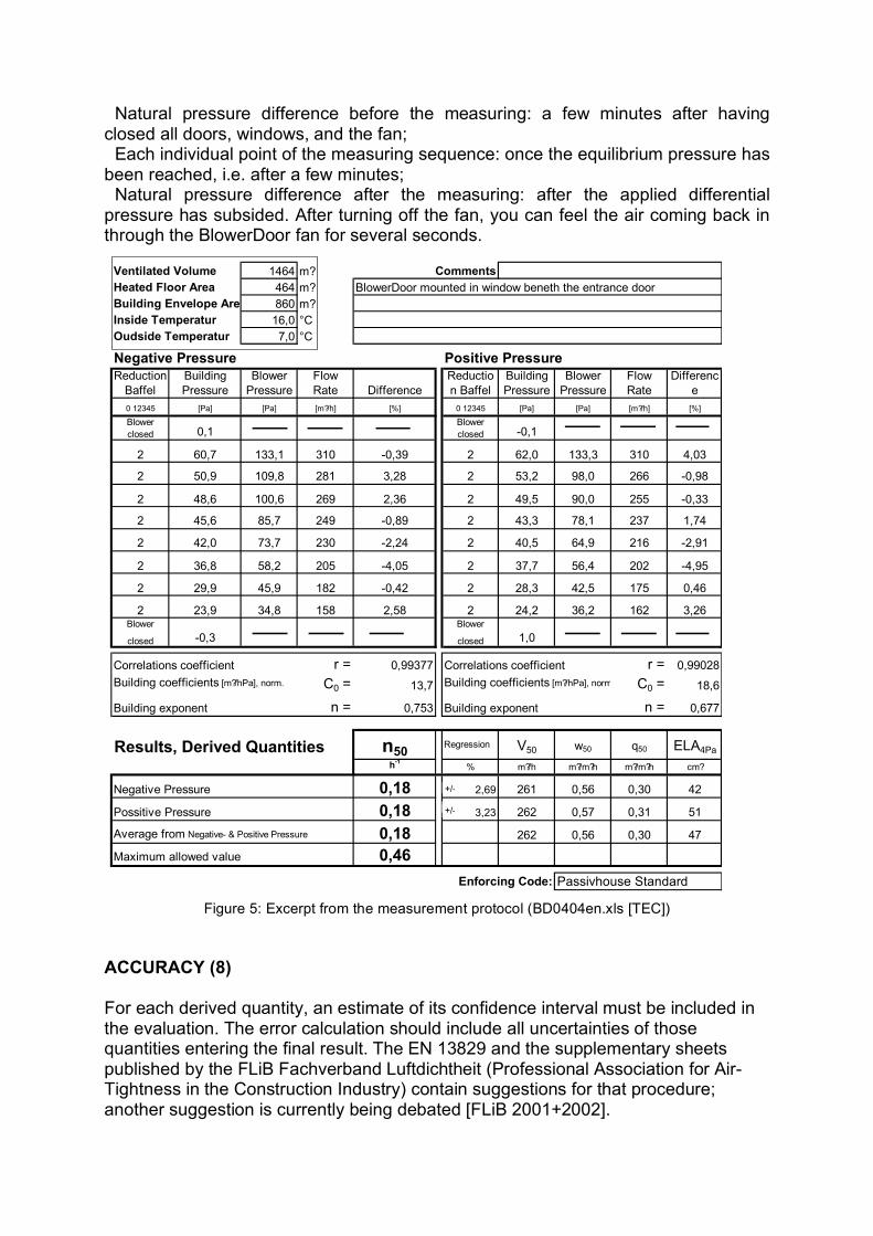
Figure 5: Excerpt from the measurement protocol (BD0404en.xls [TEC]) ACCURACY (8) For each derived quantity, an estimate of its confidence interval must be included in the evaluation. The error calculation should include all uncertainties of those quantities entering the final result. The EN 13829 and the supplementary sheets published by the FLiB Fachverband Luftdichtheit (Professional Association for Air-Tightness in the Construction Industry) contain suggestions for that procedure; another suggestion is currently being debated [FLiB 2001+2002].
Ventilated Volume 1464 m? Comments
Heated Floor Area 464 m? BlowerDoor mounted in window beneth the entrance door
Building Envelope Area 860 m?
Inside Temperatur 16,0 °C
Oudside Temperatur 7,0 °C
Negative Pressure Positive Pressure
Reduction
Baffel
Building
Pressure
Blower
Pressure
Flow
Rate Difference
Reductio
n Baffel
Building
Pressure
Blower
Pressure
Flow
Rate
Differenc
e
0 12345 [Pa] [Pa] [m?/h] [%] 0 12345 [Pa] [Pa] [m?/h] [%]
Blower
closed 0,1Blower
closed -0,1
2 60,7 133,1 310 -0,39 2 62,0 133,3 310 4,03
2 50,9 109,8 281 3,28 2 53,2 98,0 266 -0,98
2 48,6 100,6 269 2,36 2 49,5 90,0 255 -0,33
2 45,6 85,7 249 -0,89 2 43,3 78,1 237 1,74
2 42,0 73,7 230 -2,24 2 40,5 64,9 216 -2,91
2 36,8 58,2 205 -4,05 2 37,7 56,4 202 -4,95
2 29,9 45,9 182 -0,42 2 28,3 42,5 175 0,46
2 23,9 34,8 158 2,58 2 24,2 36,2 162 3,26Blower
closed -0,3
Blower
closed 1,0
Correlations coefficient r = 0,99377 Correlations coefficient r = 0,99028
Building coefficients [m?/hPa], norm. C0 = 13,7 Building coefficients [m?/hPa], norm. C0 = 18,6
Building exponent n = 0,753 Building exponent n = 0,677
Results, Derived Quantities n50 Regression V50 w50 q50 ELA4Pa
h-1
% m?/h m?/m?h m?/m?h cm?
Negative Pressure 0,18 2,69 261 0,56 0,30 42
Possitive Pressure 0,18 3,23 262 0,57 0,31 51
Average from Negative- & Positive Pressure 0,18 262 0,56 0,30 47
Maximum allowed value 0,46
Enforcing Code: Passivhouse Standard
+/-
+/-+/-+/-
The measuring system must be suitable for measuring low air flow rates. In the example from figure 5, air flow rates between 310 and 160 m³/h were adjusted for recording the measuring sequence. The building in question is a student dormitory (internal volume 1.464 m³); single-family passive houses usually have even lower air flow rates. Therefore in passive houses it makes sense to use a measuring system that is more exact than what is permissible under the European standard; the error in air flow rate configuration should be 4% rather than 7%.
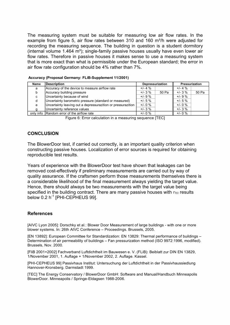
Figure 6: Error calculation in a measuring sequence [TEC] CONCLUSION The BlowerDoor test, if carried out correctly, is an important quality criterion when constructing passive houses. Localization of error sources is required for obtaining reproducible test results. Years of experience with the BlowerDoor test have shown that leakages can be removed cost-effectively if preliminary measurements are carried out by way of quality assurance. If the craftsmen perform those measurements themselves there is a considerable likelihood of the final measurement always yielding the target value. Hence, there should always be two measurements with the target value being specified in the building contract. There are many passive houses with n50 results below 0.2 h-1 [PHI-CEPHEUS 99]. References
[AIVC Lyon 2005]: Dorschky et al.: Blower Door Measurement of large buildings - with one or more blower systems. In: 26th AIVC Conference – Proceedings. Brussels, 2005.
[EN 13892]: European Committee for Standardization: EN 13829: Thermal performance of buildings – Determination of air permeability of buildings – Fan pressurization method (ISO 9972:1996, modified). Brussels, Nov. 2000.
[FliB 2001+2002] Fachverband Luftdichtheit im Bauwesen e. V. (FLiB): Beiblatt zur DIN EN 13829, 1/November 2001, 1. Auflage + 1/November 2002, 2. Auflage. Kassel.
[PHI-CEPHEUS 99] Passivhaus Institut: Untersuchung der Luftdichtheit in der Passivhaussiedlung Hannover-Kronsberg. Darmstadt 1999.
[TEC] The Energy Conservatory / BlowerDoor GmbH: Software and Manual/Handbuch Minneapolis BlowerDoor. Minneapolis / Springe-Eldagsen 1988-2006.
Accuracy (Proposal Germany: FLiB-Supplement 11/2001)
Name Description
a Accuracy of the device to measure airflow rate +/- 4 % +/- 4 %
b Accuracy building pressure +/- 3 % 50 Pa +/- 3 % 50 Pa
c Uncertainty because of wind +/- 9 % +/- 9 %
d Uncertainty barometric pressure (standard or measured) +/- 5 % +/- 5 %
e Uncertainty leaving out a depressurazition or pressurazition +/- 0 % +/- 0 %
g Uncertainty reference values +/- 3 % +/- 3 %
only info Random error of the airflow rate +/- 0 % +/- 0 %
Depressurization Pressurization
Recommended