Bio-Potential Amplifiers
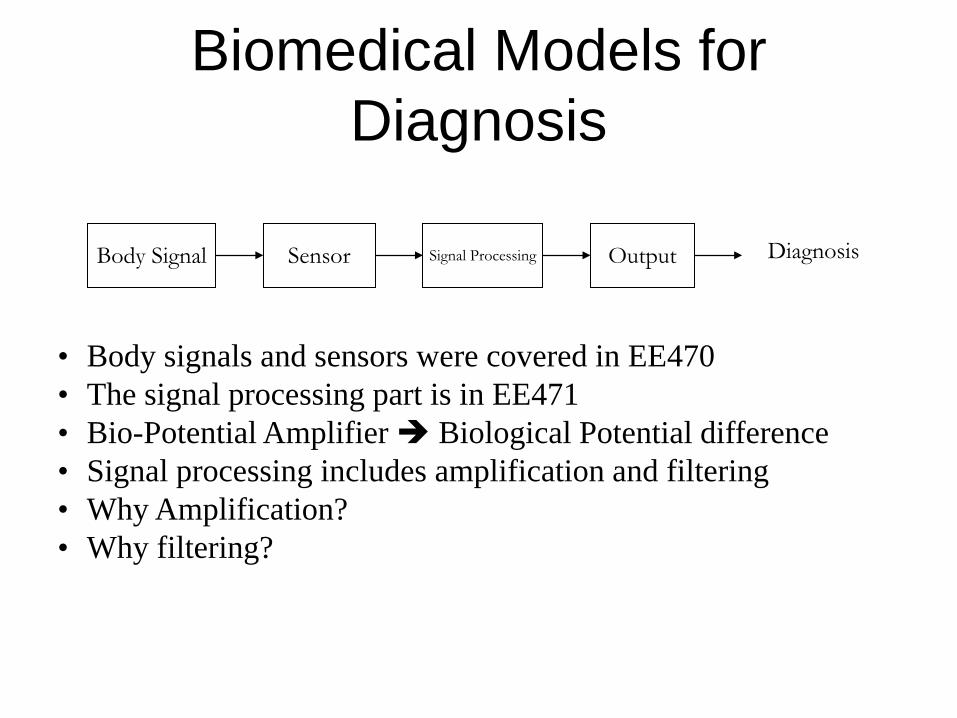
Biomedical Models for Diagnosis
Body Signal Sensor Signal Processing Output Diagnosis
• Body signals and sensors were covered in EE470• The signal processing part is in EE471• Bio-Potential Amplifier Biological Potential difference• Signal processing includes amplification and filtering• Why Amplification?• Why filtering?
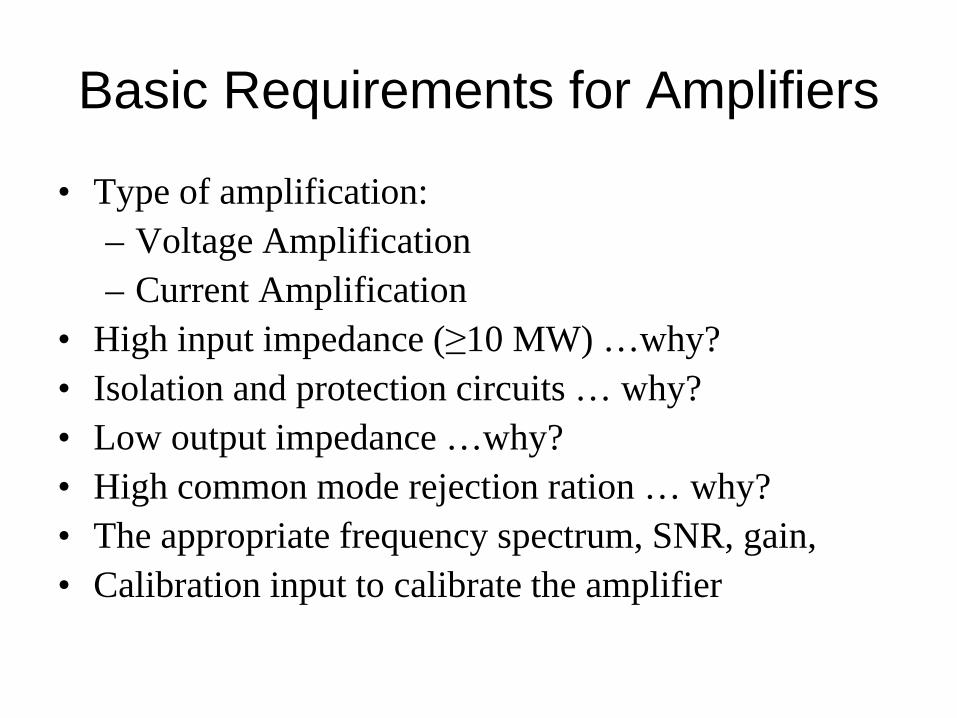
Basic Requirements for Amplifiers
• Type of amplification:– Voltage Amplification– Current Amplification
• High input impedance (≥10 MW) …why?• Isolation and protection circuits … why?• Low output impedance …why?• High common mode rejection ration … why?• The appropriate frequency spectrum, SNR, gain,• Calibration input to calibrate the amplifier
Example of Bio-Potential Amplifier ECG Amplifier
Origins of the electrocardiogram• Blood Cycle• The cardiac vector• The ECG waveform• Indicator of a good ECG• 12-lead electrocardiography

Blood Cycle of the Heart
• Objectives of the cycle:– Provide Oxygenated blood to all body cells– Remove Carbon-Dioxide accumulating in cells
• Two Blood Cycles simultaneously– Pulmonary cycle add oxygen and remove Co2
– Blood Cycle carry oxygen to body cells
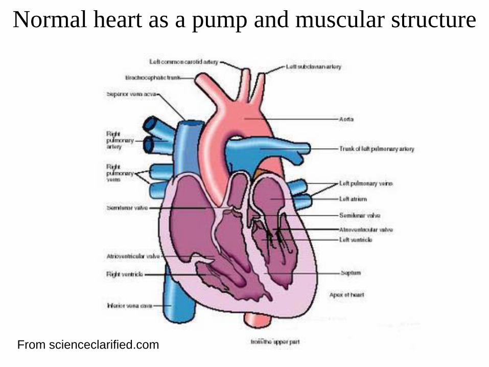
Normal heart as a pump and muscular structure
From scienceclarified.com
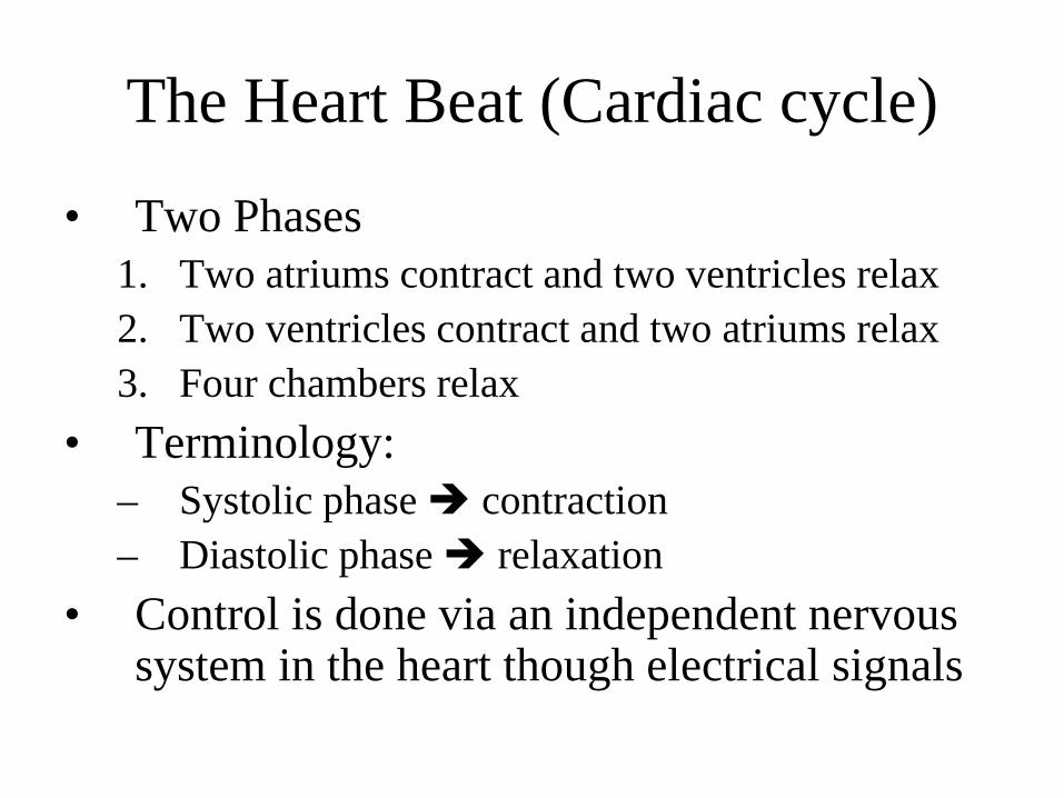
The Heart Beat (Cardiac cycle)
• Two Phases1. Two atriums contract and two ventricles relax2. Two ventricles contract and two atriums relax3. Four chambers relax
• Terminology:– Systolic phase contraction– Diastolic phase relaxation
• Control is done via an independent nervous system in the heart though electrical signals
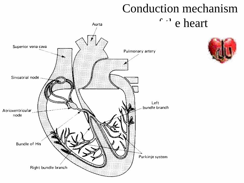
Conduction mechanism of the heart
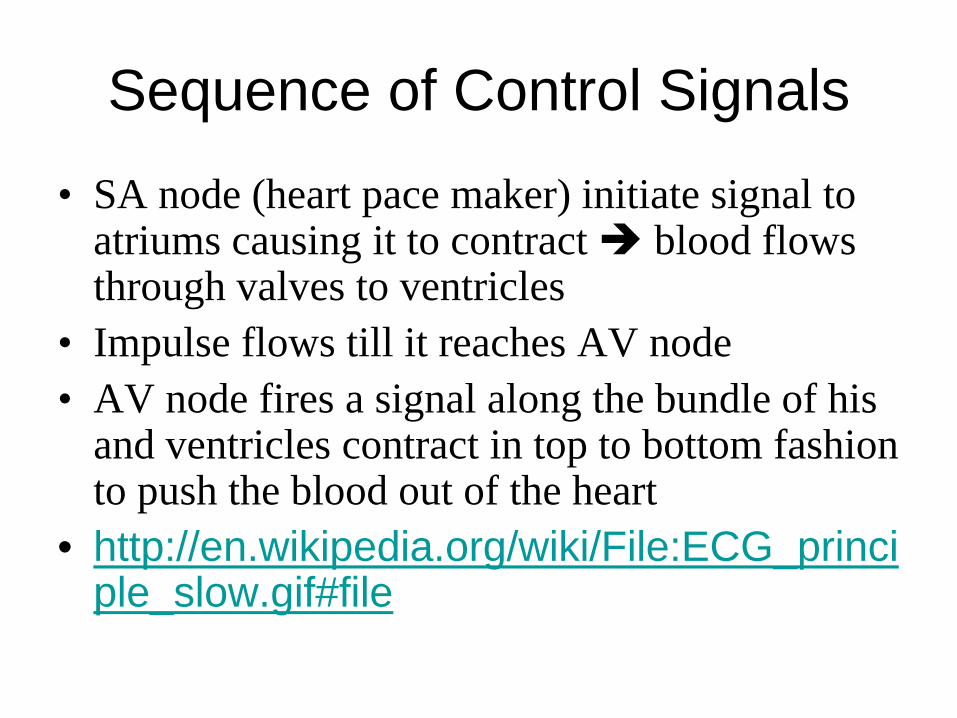
Sequence of Control Signals
• SA node (heart pace maker) initiate signal to atriums causing it to contract blood flows through valves to ventricles
• Impulse flows till it reaches AV node• AV node fires a signal along the bundle of his
and ventricles contract in top to bottom fashion to push the blood out of the heart
• http://en.wikipedia.org/wiki/File:ECG_principle_slow.gif#file
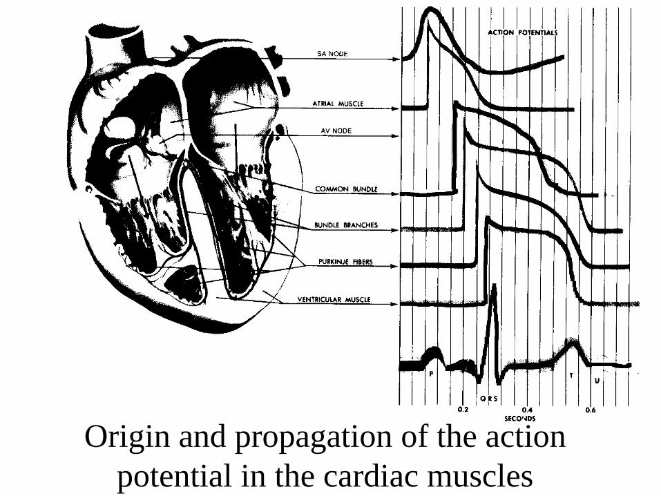
Origin and propagation of the action potential in the cardiac muscles
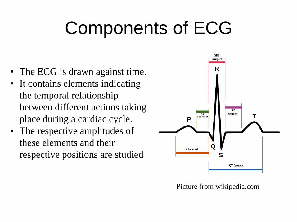
Components of ECG
• The ECG is drawn against time. • It contains elements indicating
the temporal relationship between different actions taking place during a cardiac cycle.
• The respective amplitudes of these elements and their respective positions are studied
Picture from wikipedia.com
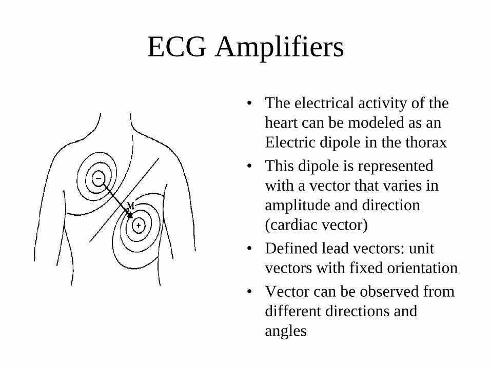
ECG Amplifiers
• The electrical activity of the heart can be modeled as an Electric dipole in the thorax
• This dipole is represented with a vector that varies in amplitude and direction (cardiac vector)
• Defined lead vectors: unit vectors with fixed orientation
• Vector can be observed from different directions and angles
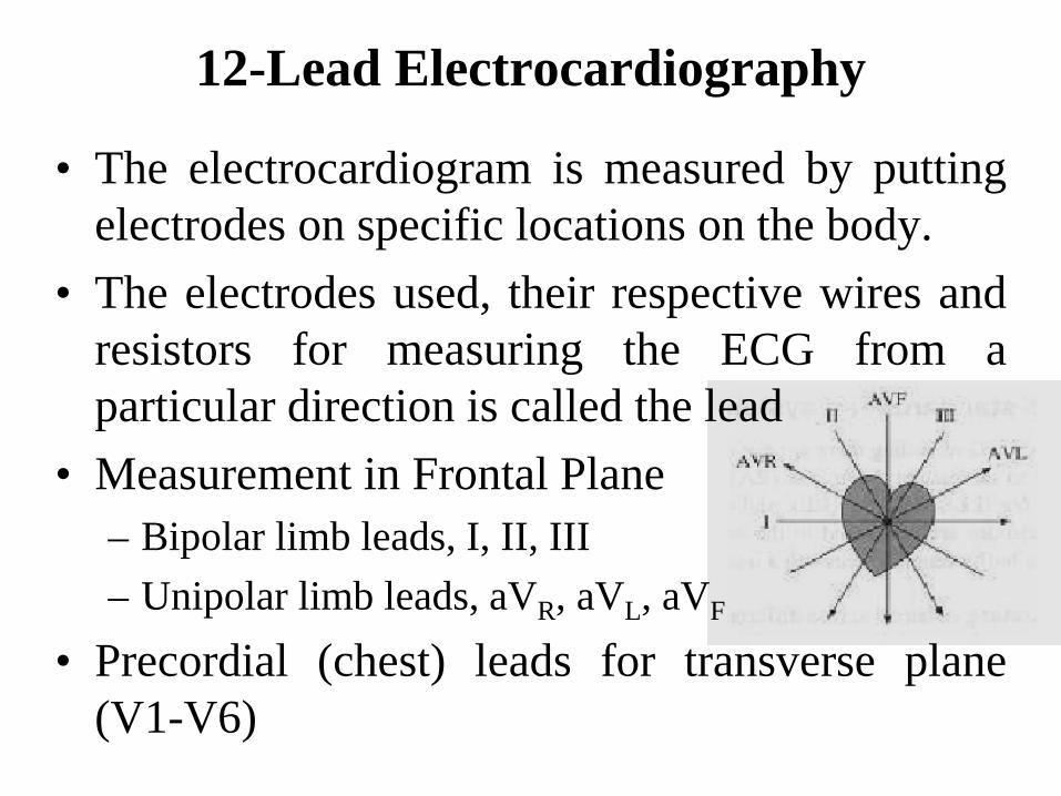
• The electrocardiogram is measured by puttingelectrodes on specific locations on the body.
• The electrodes used, their respective wires andresistors for measuring the ECG from aparticular direction is called the lead
• Measurement in Frontal Plane– Bipolar limb leads, I, II, III– Unipolar limb leads, aVR, aVL, aVF
• Precordial (chest) leads for transverse plane(V1-V6)
12-Lead Electrocardiography
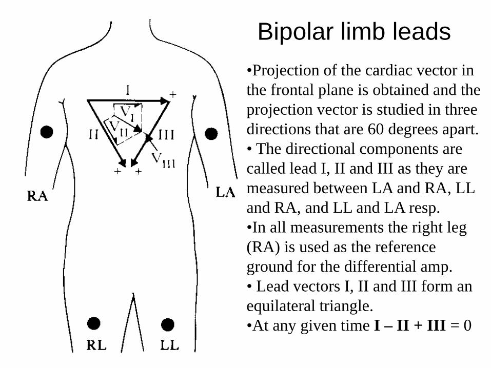
Bipolar limb leads•Projection of the cardiac vector in the frontal plane is obtained and the projection vector is studied in three directions that are 60 degrees apart.• The directional components are called lead I, II and III as they are measured between LA and RA, LL and RA, and LL and LA resp. •In all measurements the right leg (RA) is used as the reference ground for the differential amp.• Lead vectors I, II and III form an equilateral triangle. •At any given time I – II + III = 0
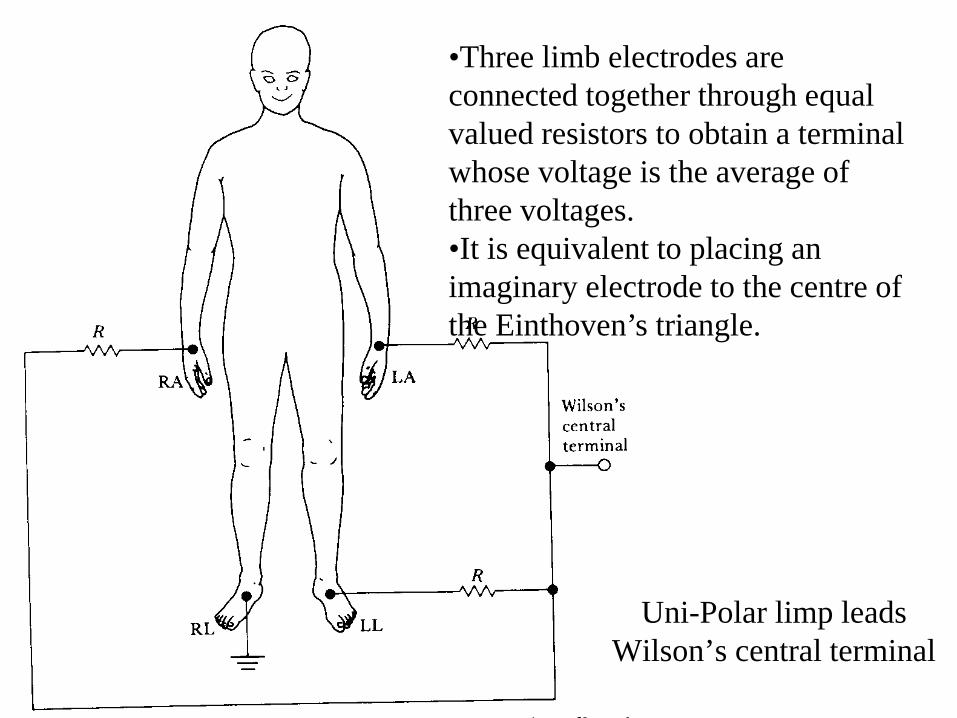
•Three limb electrodes are connected together through equal valued resistors to obtain a terminal whose voltage is the average of three voltages. •It is equivalent to placing an imaginary electrode to the centre of the Einthoven’s triangle.
Uni-Polar limp leadsWilson’s central terminal
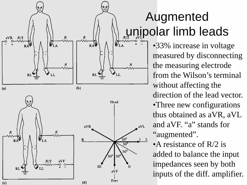
Augmented unipolar limb leads
•33% increase in voltage measured by disconnecting the measuring electrode from the Wilson’s terminal without affecting the direction of the lead vector.•Three new configurations thus obtained as aVR, aVL and aVF. “a” stands for “augmented”. •A resistance of R/2 is added to balance the input impedances seen by both inputs of the diff. amplifier.
Homework 1Bio-Potential Amplifiers and ECG leads
1. Explain why Bio-Potential Amplifiers need to have the following requirements:
– High Input Impedance– Low output impedance– Frequency response appropriate to the signal– Isolation Circuit
2. Show that the voltage at wilson central point (figure 6.4) is the average of the voltages at each node
3. Show that voltage at the augmented lead shown in figure 6.5 increases the output voltage and calculate this increase
Notes:• Homework due at beginning of Tue Oct 20th class • Late submission are subject to 10% decrease for everyday after the class• No late submissions would be accepted after Sun Oct 24th class

Bio-Potential Amplifier II
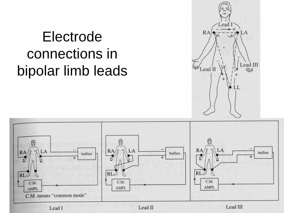
Electrode connections in
bipolar limb leads
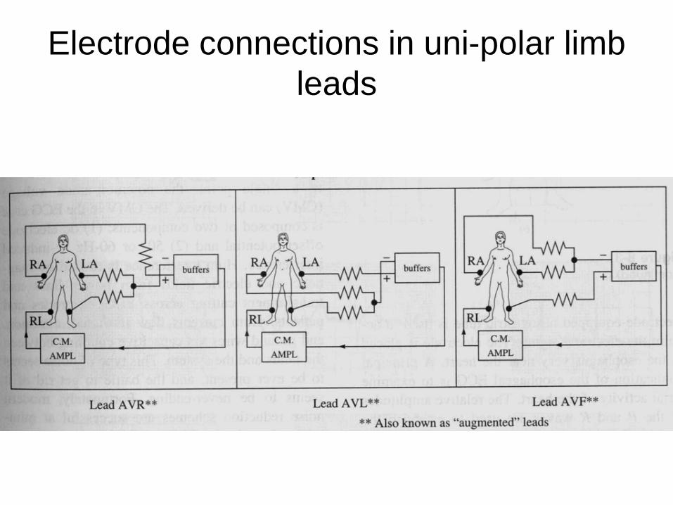
Electrode connections in uni-polar limb leads
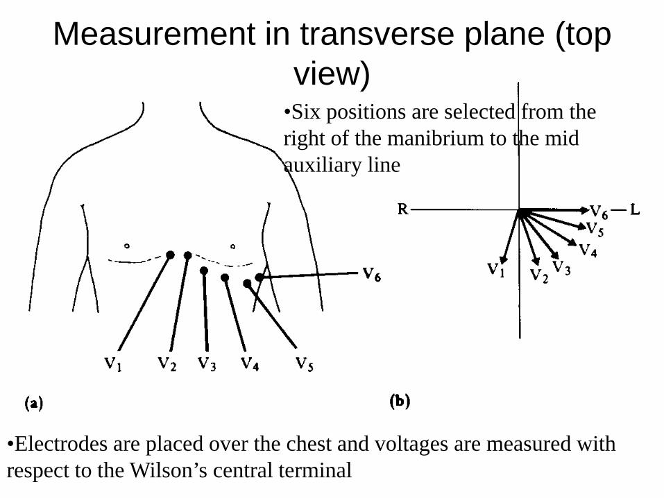
Measurement in transverse plane (top view)
•Electrodes are placed over the chest and voltages are measured with respect to the Wilson’s central terminal
•Six positions are selected from the right of the manibrium to the mid auxiliary line
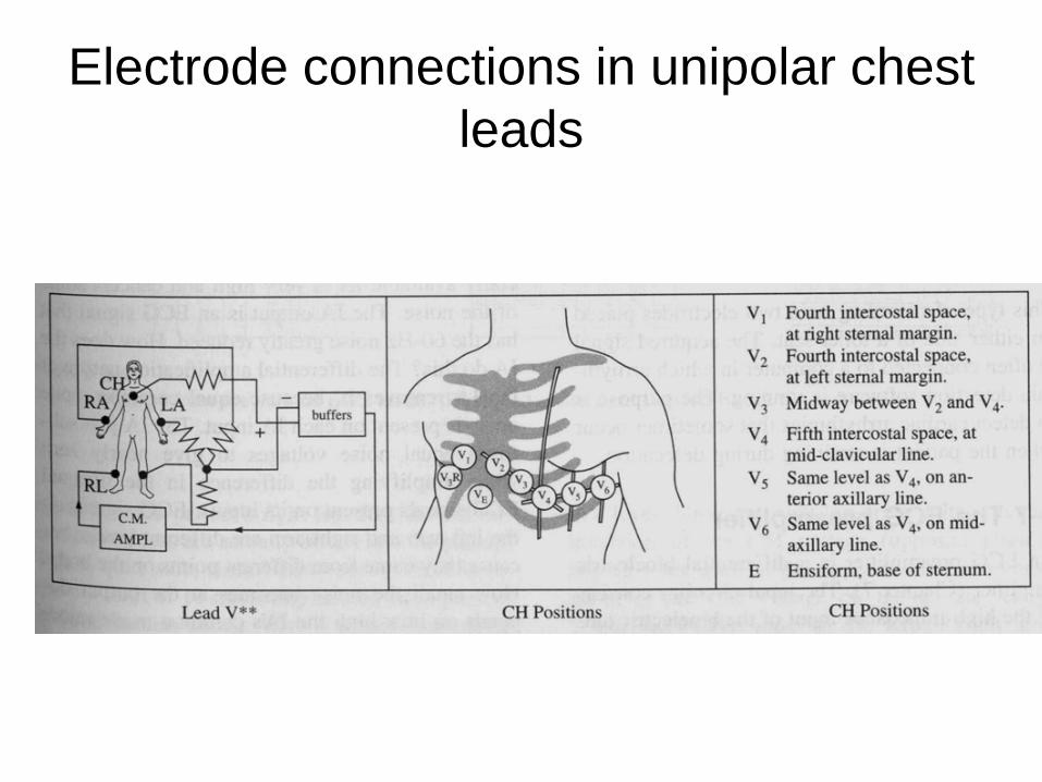
Electrode connections in unipolar chest leads
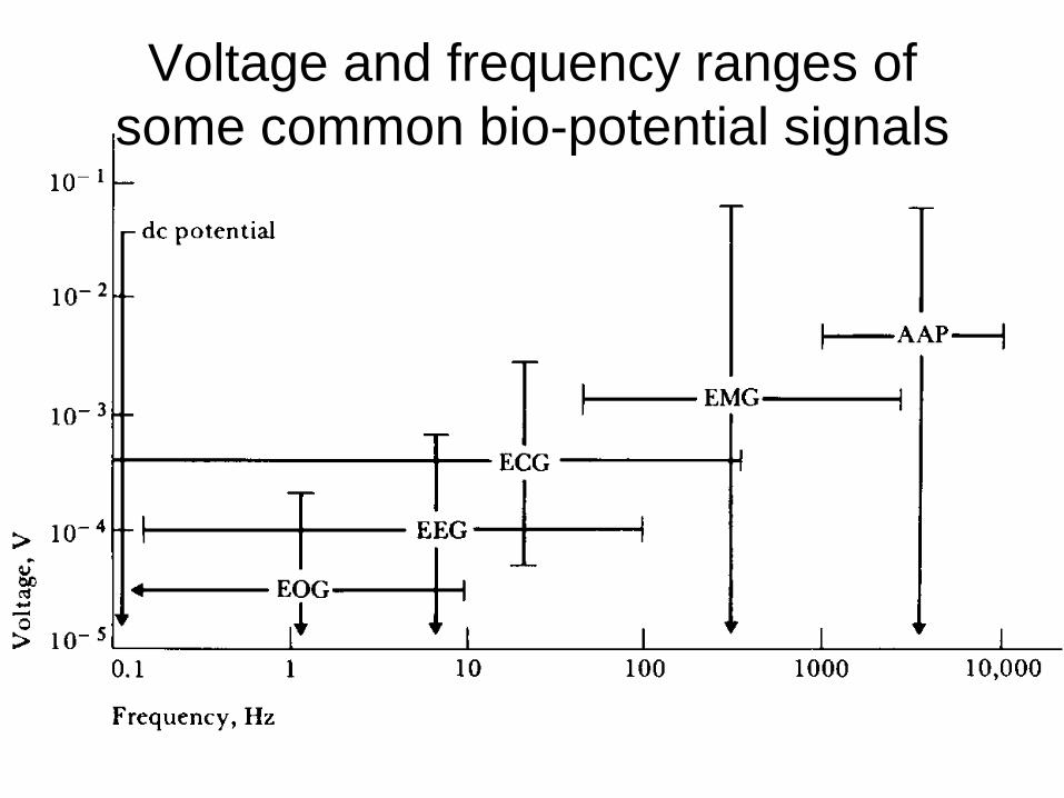
Voltage and frequency ranges of some common bio-potential signals
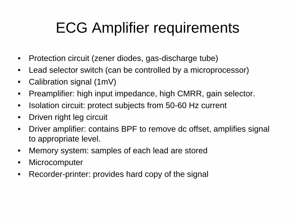
ECG Amplifier requirements
• Protection circuit (zener diodes, gas-discharge tube)• Lead selector switch (can be controlled by a microprocessor) • Calibration signal (1mV)• Preamplifier: high input impedance, high CMRR, gain selector.• Isolation circuit: protect subjects from 50-60 Hz current• Driven right leg circuit• Driver amplifier: contains BPF to remove dc offset, amplifies signal
to appropriate level.• Memory system: samples of each lead are stored• Microcomputer• Recorder-printer: provides hard copy of the signal
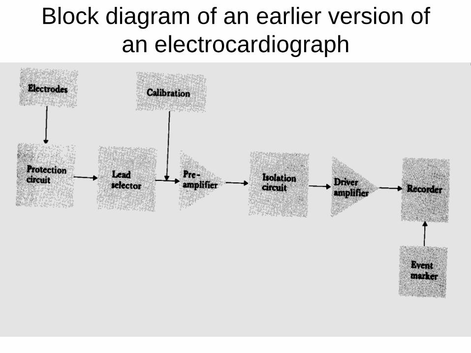
Block diagram of an earlier version of an electrocardiograph
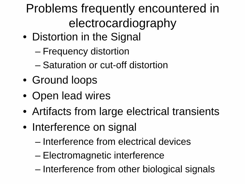
Problems frequently encountered in electrocardiography
• Distortion in the Signal– Frequency distortion– Saturation or cut-off distortion
• Ground loops• Open lead wires• Artifacts from large electrical transients• Interference on signal
– Interference from electrical devices– Electromagnetic interference– Interference from other biological signals
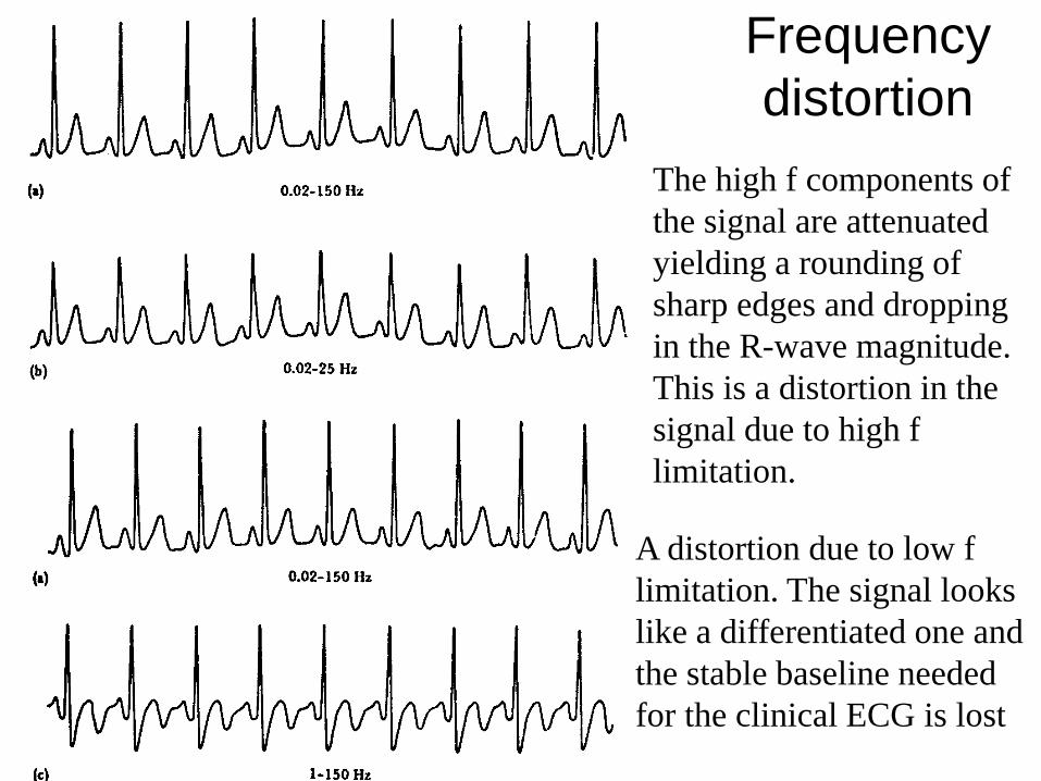
Frequency distortion
The high f components of the signal are attenuated yielding a rounding of sharp edges and dropping in the R-wave magnitude. This is a distortion in the signal due to high f limitation.
A distortion due to low f limitation. The signal looks like a differentiated one and the stable baseline needed for the clinical ECG is lost
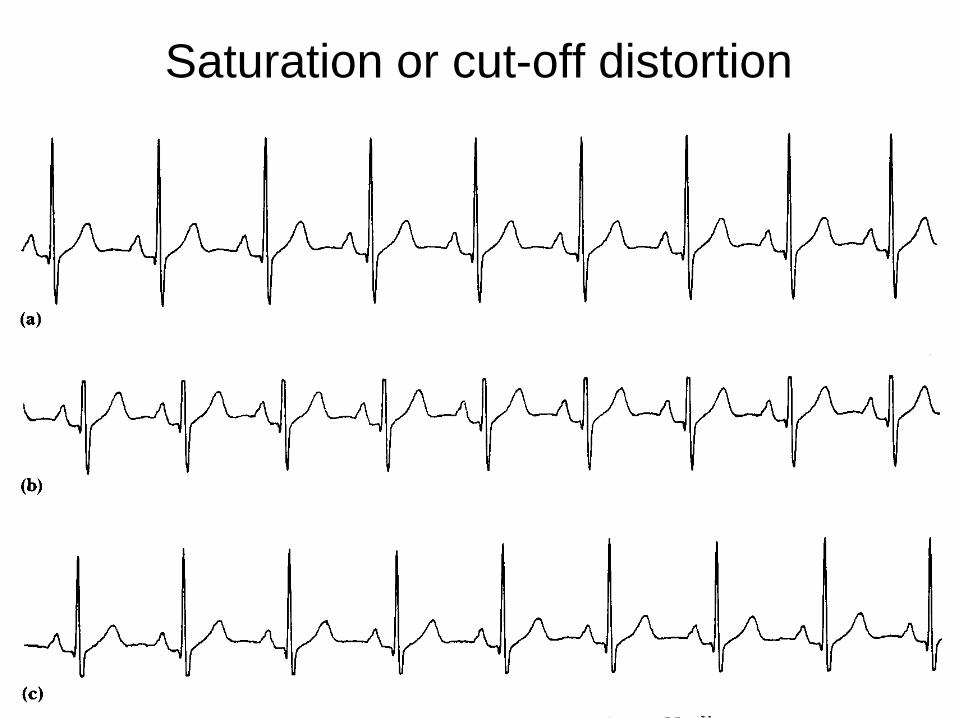
Saturation or cut-off distortion
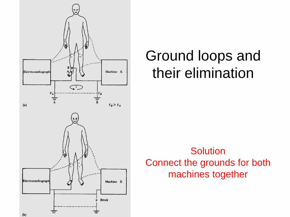
Ground loops and their elimination
SolutionConnect the grounds for both
machines together
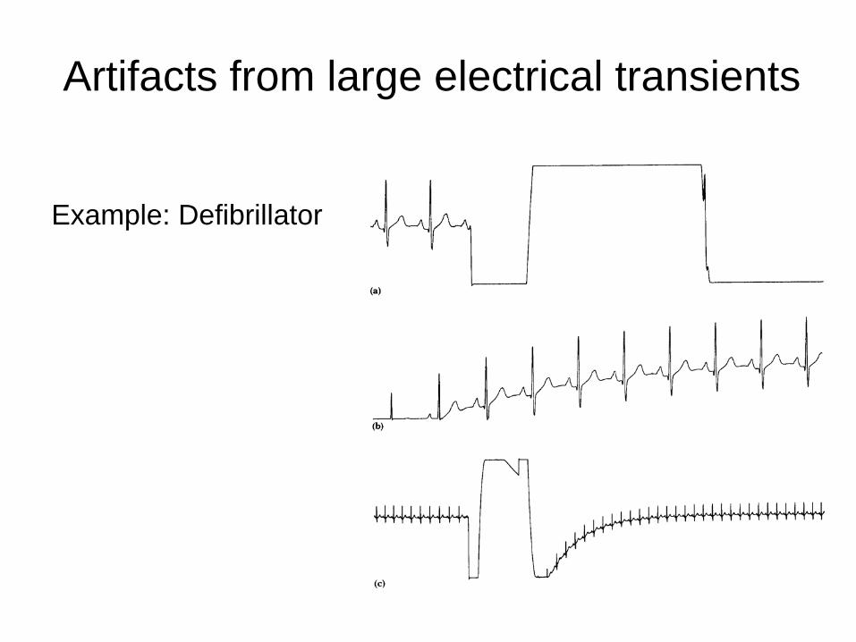
Artifacts from large electrical transients
Example: Defibrillator
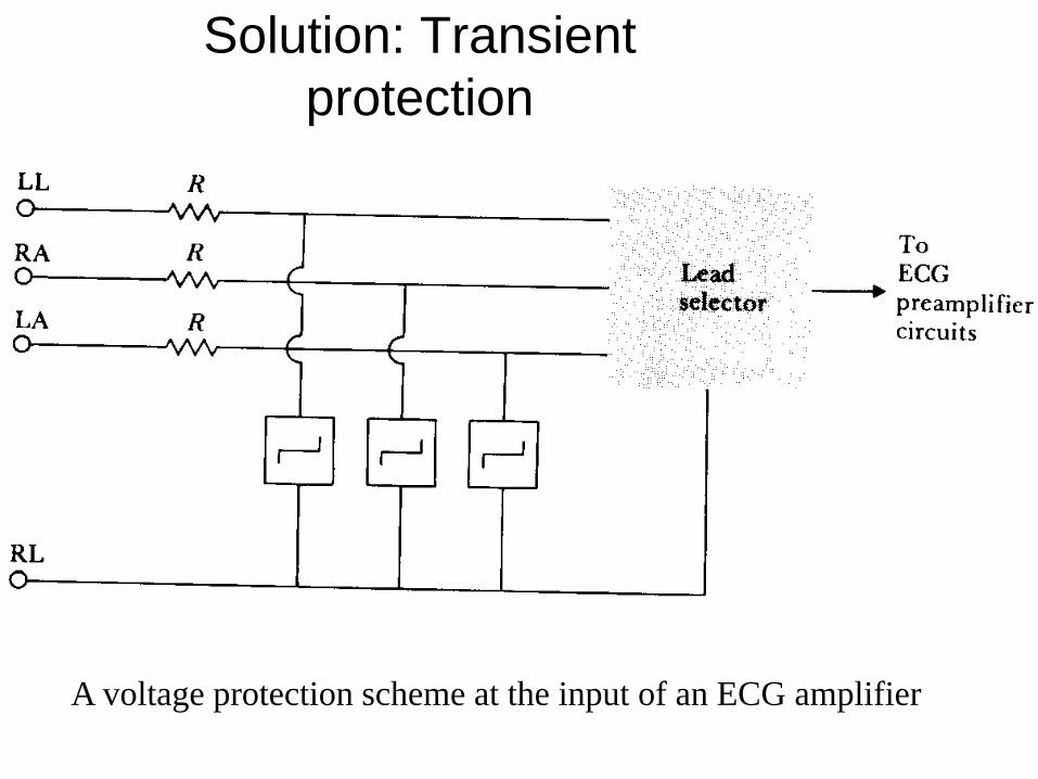
Solution: Transient protection
A voltage protection scheme at the input of an ECG amplifier
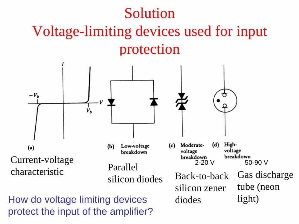
SolutionVoltage-limiting devices used for input
protection
Gas discharge tube (neon light)
Back-to-back silicon zener diodes
Parallel silicon diodes
Current-voltage characteristic
2-20 V 50-90 V
How do voltage limiting devices protect the input of the amplifier?
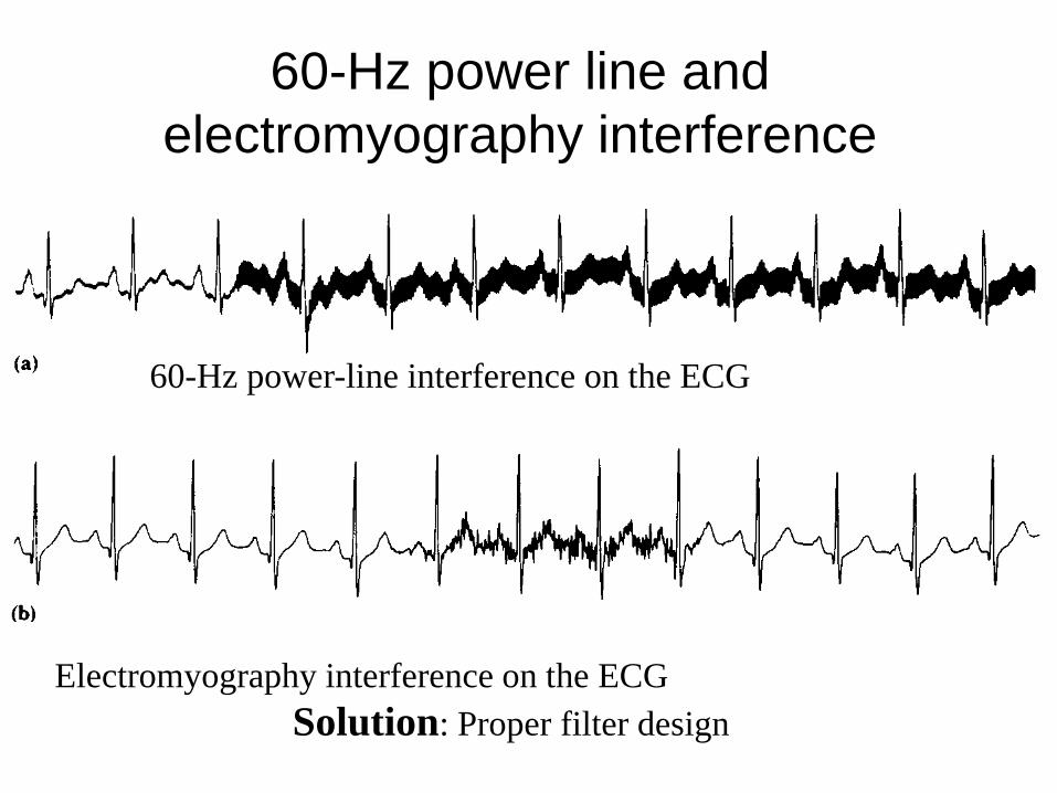
60-Hz power line and electromyography interference
60-Hz power-line interference on the ECG
Electromyography interference on the ECGSolution: Proper filter design
Lead Dropping
• Lead drop = No ECG = Patient is Dead !!• Medical staff not EE specialists• Training example
Solution• Lead drop detector circuit
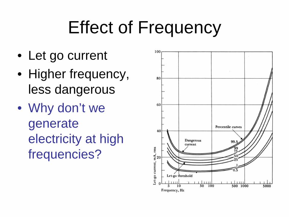
Effect of Frequency• Let go current• Higher frequency,
less dangerous • Why don’t we
generate electricity at high frequencies?
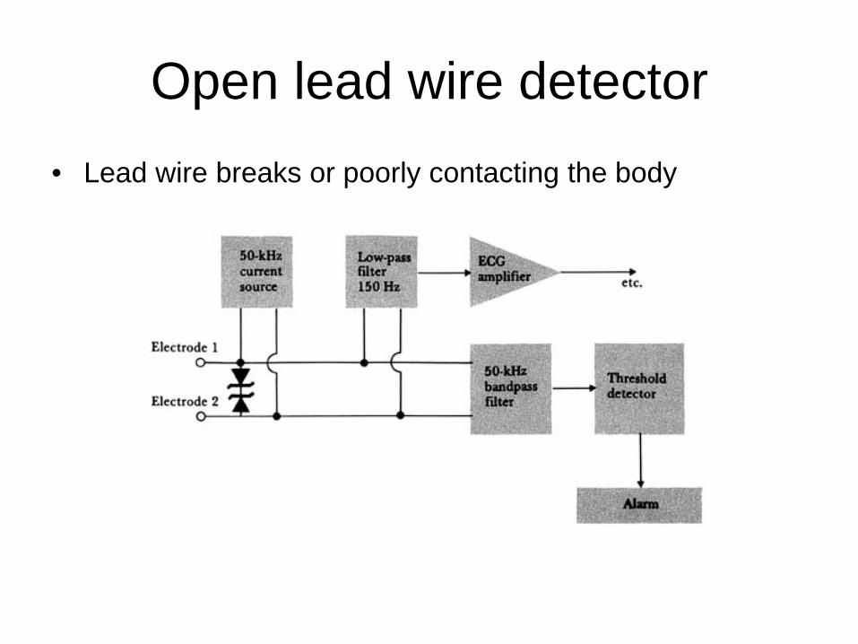
Open lead wire detector• Lead wire breaks or poorly contacting the body
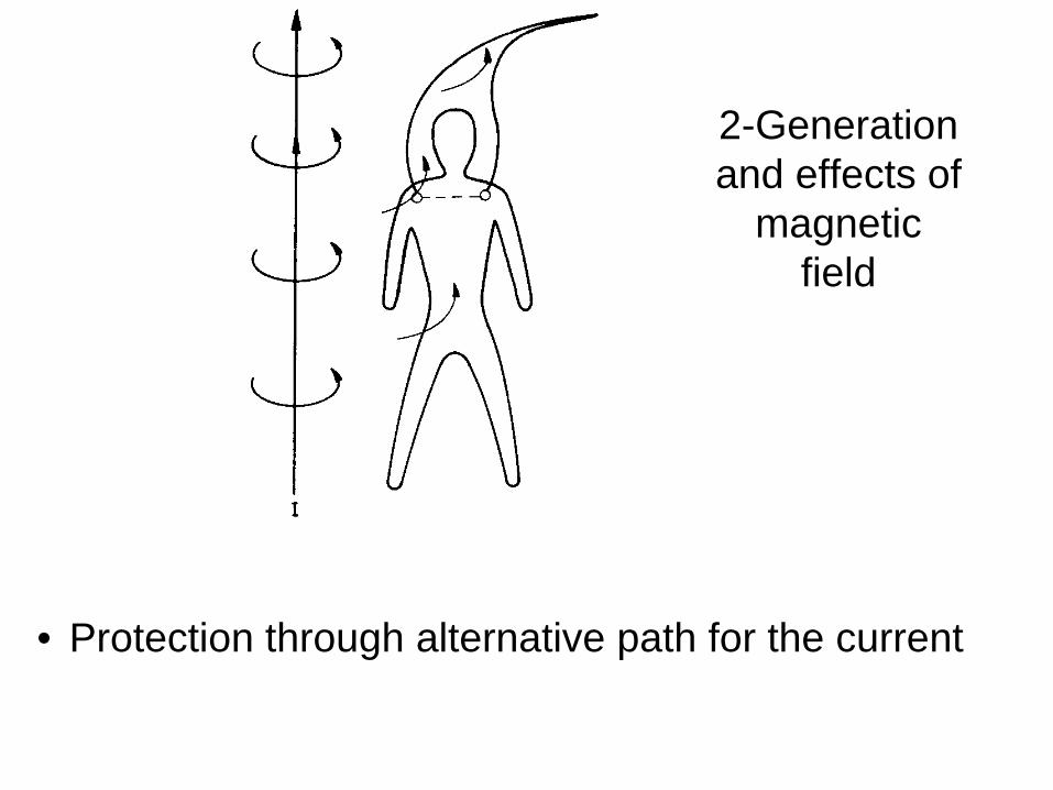
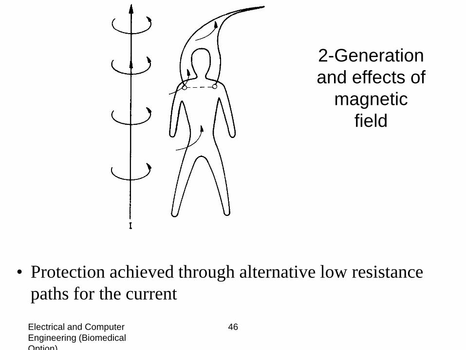
2-Generation and effects of
magnetic field
• Protection through alternative path for the current
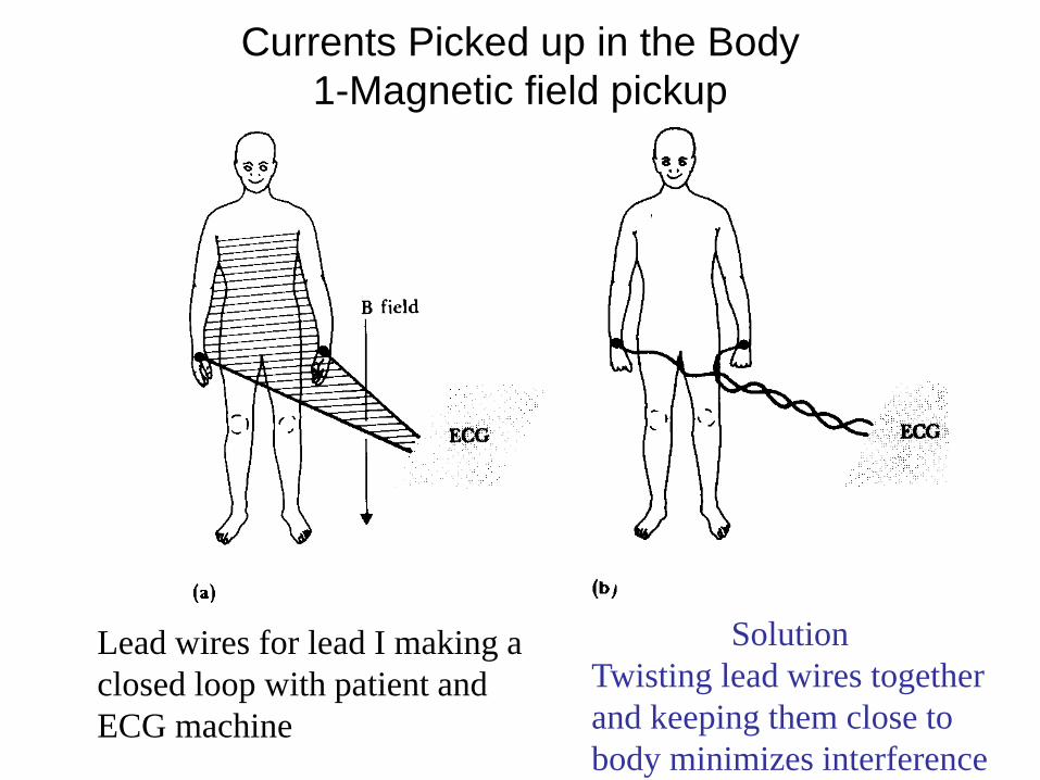
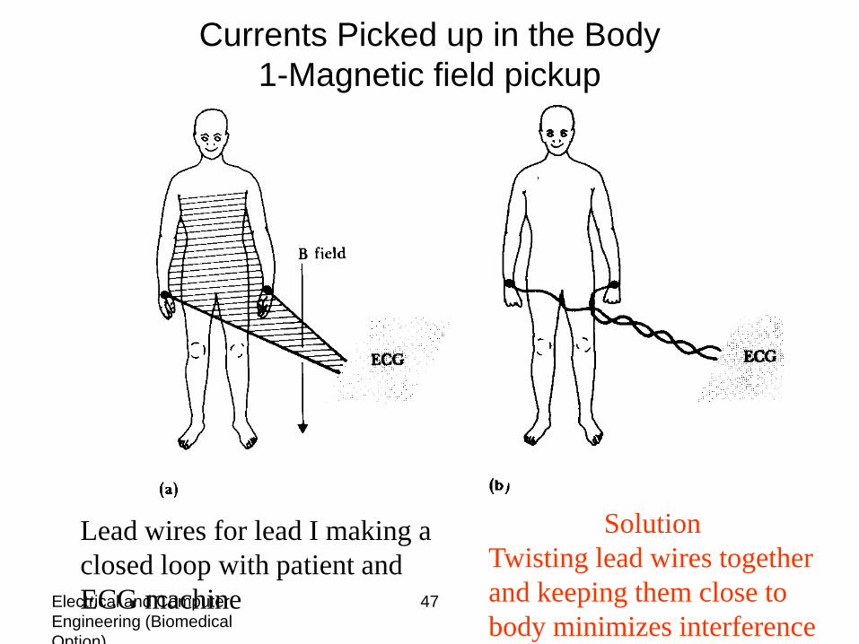
Currents Picked up in the Body1-Magnetic field pickup
SolutionTwisting lead wires together and keeping them close to body minimizes interference
Lead wires for lead I making a closed loop with patient and ECG machine
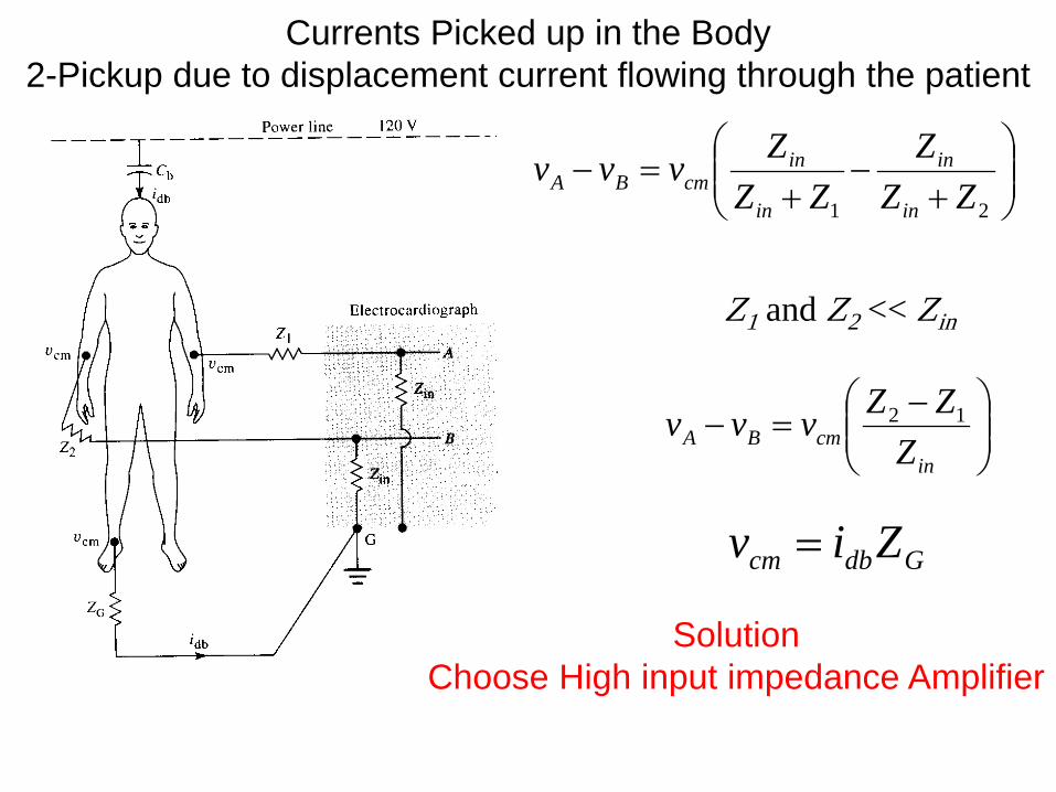
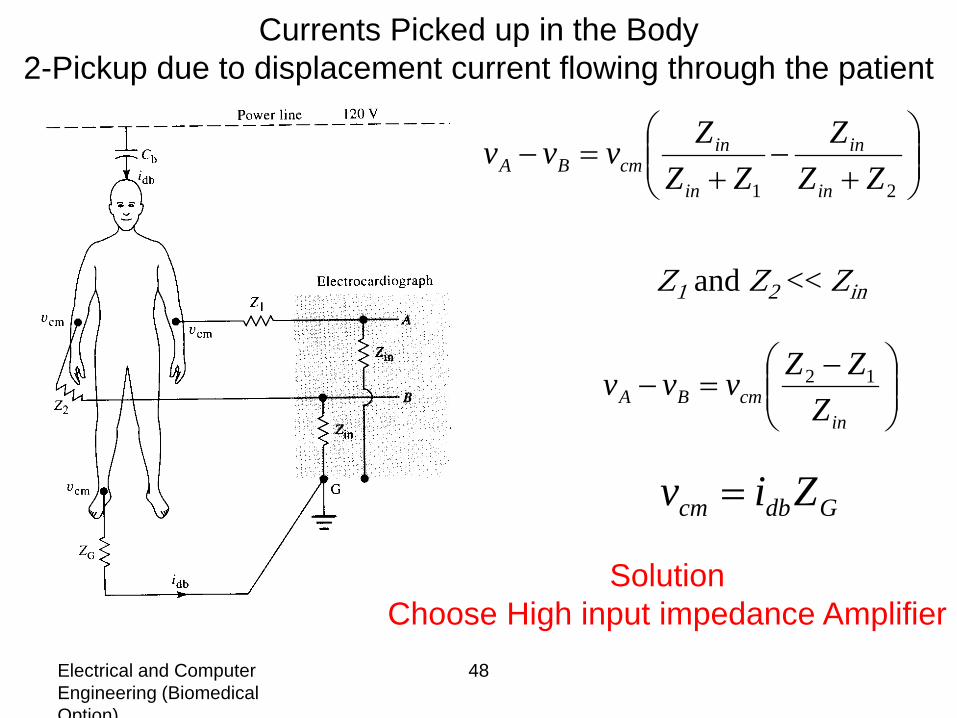
Currents Picked up in the Body2-Pickup due to displacement current flowing through the patient
Gdbcm Ziv =
−=−
incmBA Z
ZZvvv 12
Z1 and Z2 << Zin
+
−+
=−21 ZZ
ZZZ
Zvvvin
in
in
incmBA
SolutionChoose High input impedance Amplifier
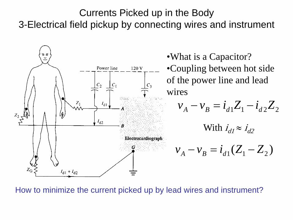
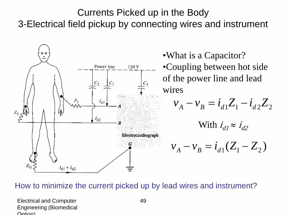
Currents Picked up in the Body3-Electrical field pickup by connecting wires and instrument
•What is a Capacitor?•Coupling between hot side of the power line and lead wires
2211 ZiZivv ddBA −=−
With id1 ≈ id2
)( 211 ZZivv dBA −=−
How to minimize the current picked up by lead wires and instrument?
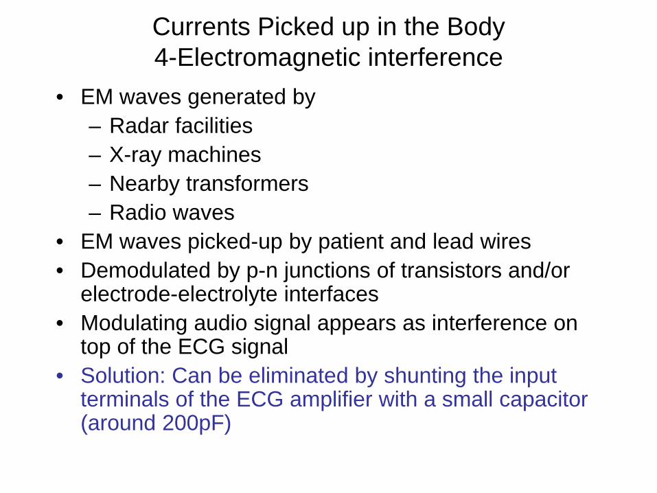
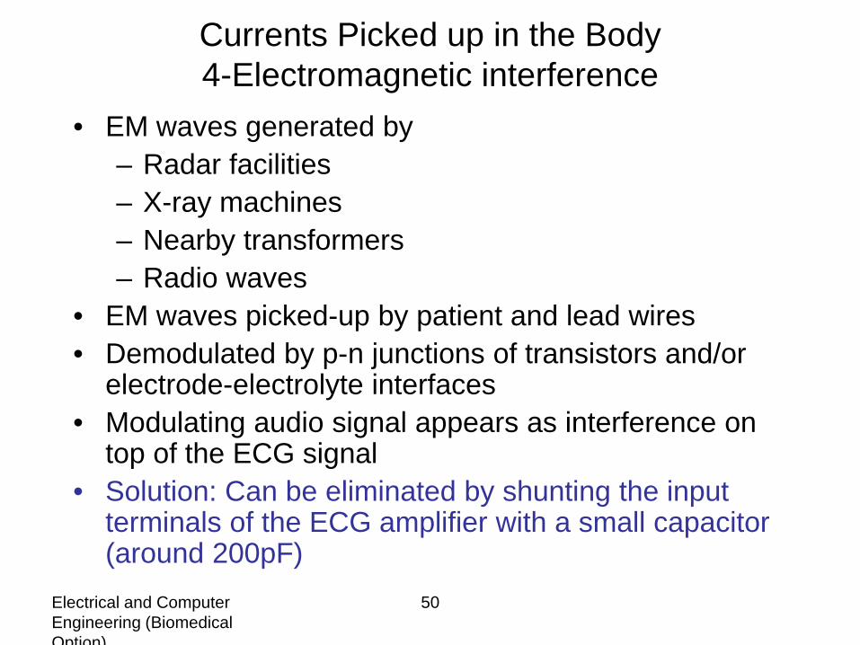
Currents Picked up in the Body4-Electromagnetic interference
• EM waves generated by– Radar facilities– X-ray machines– Nearby transformers– Radio waves
• EM waves picked-up by patient and lead wires• Demodulated by p-n junctions of transistors and/or
electrode-electrolyte interfaces• Modulating audio signal appears as interference on
top of the ECG signal• Solution: Can be eliminated by shunting the input
terminals of the ECG amplifier with a small capacitor (around 200pF)
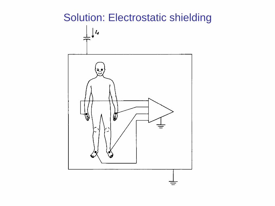
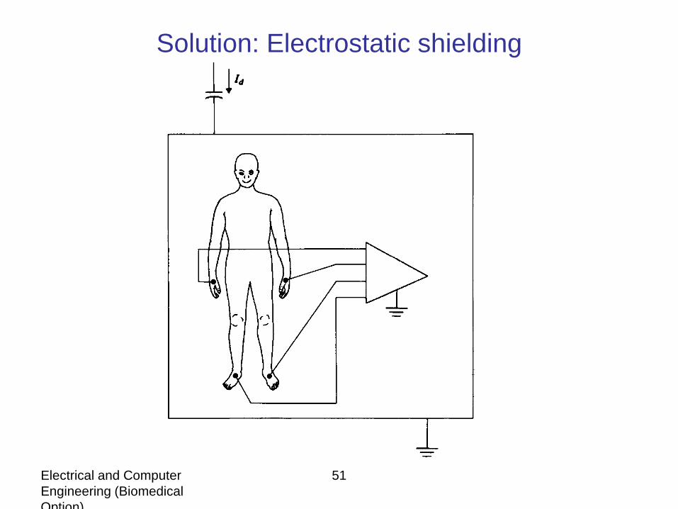
Solution: Electrostatic shielding
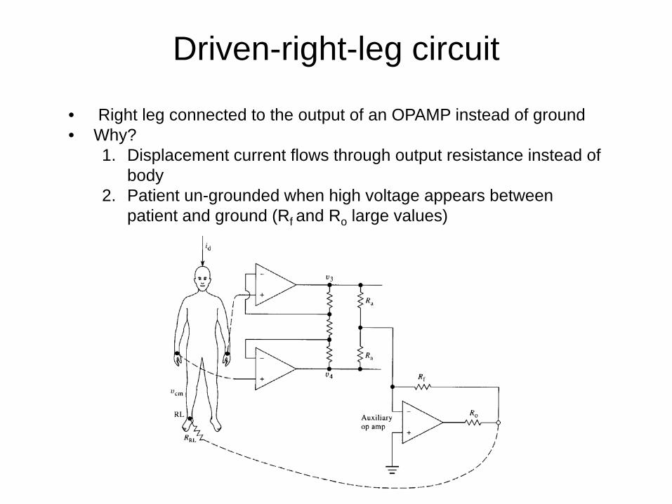
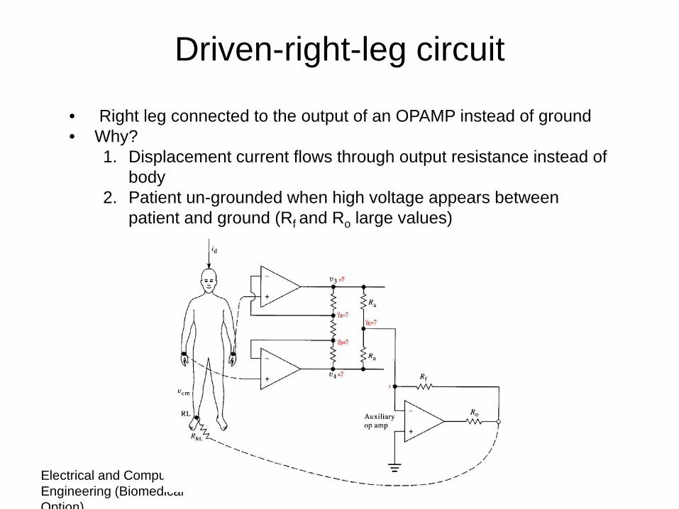
Driven-right-leg circuit
• Right leg connected to the output of an OPAMP instead of ground• Why?
1. Displacement current flows through output resistance instead of body
2. Patient un-grounded when high voltage appears between patient and ground (Rf and Ro large values)
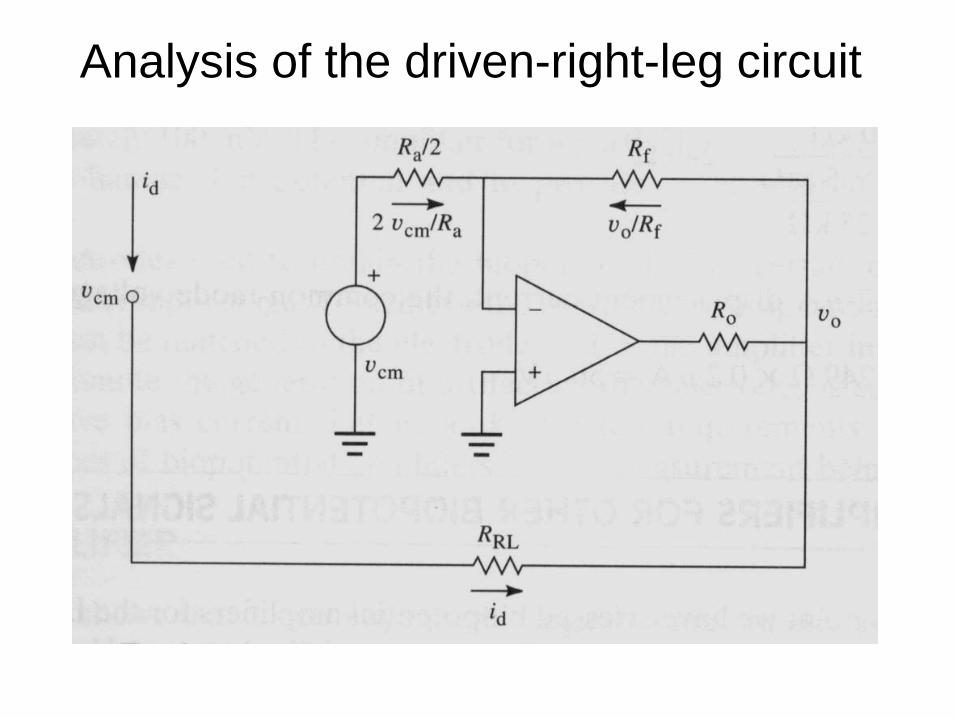
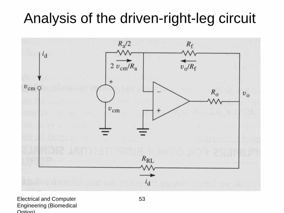
Analysis of the driven-right-leg circuit
Electrical and Computer Engineering (Biomedical Option)
45
Bio-Potential Amplifiers 3
Electrical and Computer Engineering (Biomedical Option)
46
2-Generation and effects of
magnetic field
• Protection achieved through alternative low resistance paths for the current
Electrical and Computer Engineering (Biomedical Option)
47
Currents Picked up in the Body1-Magnetic field pickup
SolutionTwisting lead wires together and keeping them close to body minimizes interference
Lead wires for lead I making a closed loop with patient and ECG machine
Electrical and Computer Engineering (Biomedical Option)
48
Currents Picked up in the Body2-Pickup due to displacement current flowing through the patient
Gdbcm Ziv =
−=−
incmBA Z
ZZvvv 12
Z1 and Z2 << Zin
+
−+
=−21 ZZ
ZZZ
Zvvvin
in
in
incmBA
SolutionChoose High input impedance Amplifier
Electrical and Computer Engineering (Biomedical Option)
49
Currents Picked up in the Body3-Electrical field pickup by connecting wires and instrument
•What is a Capacitor?•Coupling between hot side of the power line and lead wires
2211 ZiZivv ddBA −=−
With id1 ≈ id2
)( 211 ZZivv dBA −=−
How to minimize the current picked up by lead wires and instrument?
Electrical and Computer Engineering (Biomedical Option)
50
Currents Picked up in the Body4-Electromagnetic interference
• EM waves generated by– Radar facilities– X-ray machines– Nearby transformers– Radio waves
• EM waves picked-up by patient and lead wires• Demodulated by p-n junctions of transistors and/or
electrode-electrolyte interfaces• Modulating audio signal appears as interference on
top of the ECG signal• Solution: Can be eliminated by shunting the input
terminals of the ECG amplifier with a small capacitor (around 200pF)
Electrical and Computer Engineering (Biomedical Option)
51
Solution: Electrostatic shielding
Electrical and Computer Engineering (Biomedical Option)
52
Driven-right-leg circuit
• Right leg connected to the output of an OPAMP instead of ground• Why?
1. Displacement current flows through output resistance instead of body
2. Patient un-grounded when high voltage appears between patient and ground (Rf and Ro large values)
Electrical and Computer Engineering (Biomedical Option)
53
Analysis of the driven-right-leg circuit
Electrical and Computer Engineering (Biomedical Option)
54
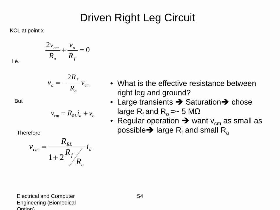
02
=+f
o
a
cm
Rv
Rv
cma
fo v
RR
v2
−=
odRLcm viRv +=
KCL at point x
i.e.
But
Therefore
d
a
f
RLcm i
RR
Rv21+
=
• What is the effective resistance between right leg and ground?
• Large transients Saturation chose large Rf and Ro =~ 5 MΩ
• Regular operation want vcm as small as possible large Rf and small Ra
Driven Right Leg Circuit

Bio-Potential Amplifiers -4
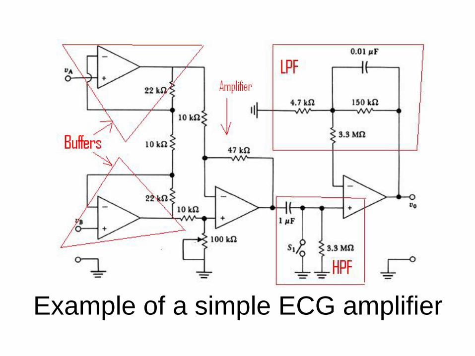
Example of a simple ECG amplifier

Examples of Bio-Potential Amlifiers
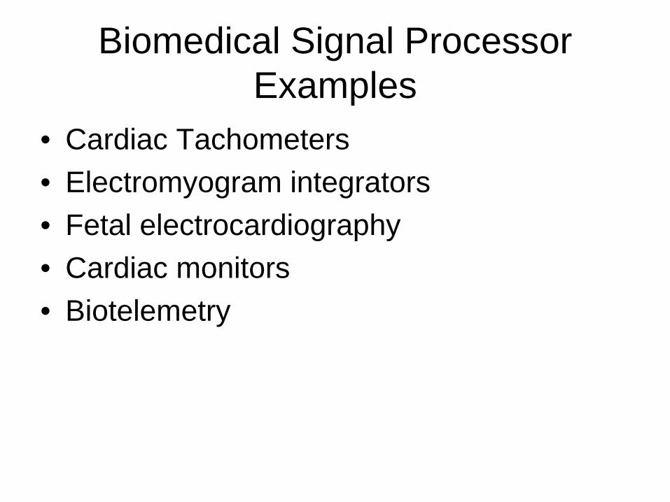
Biomedical Signal Processor Examples
• Cardiac Tachometers• Electromyogram integrators• Fetal electrocardiography• Cardiac monitors• Biotelemetry
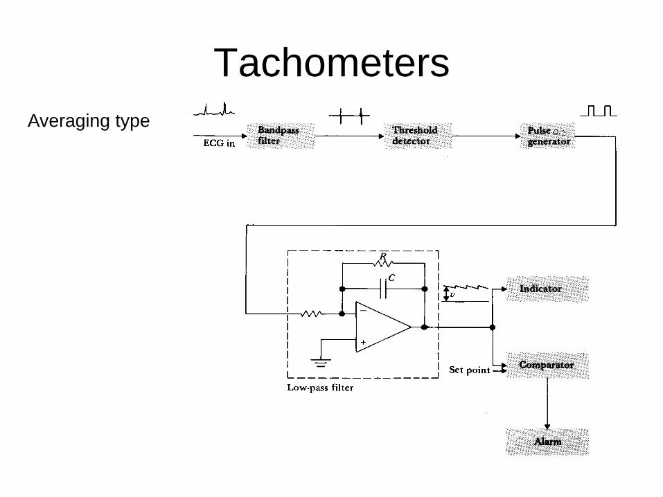
TachometersAveraging type
Tachometers
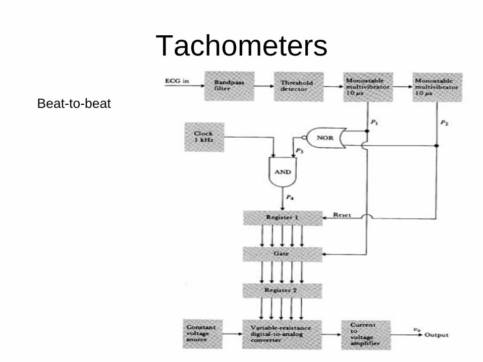
Beat-to-beat
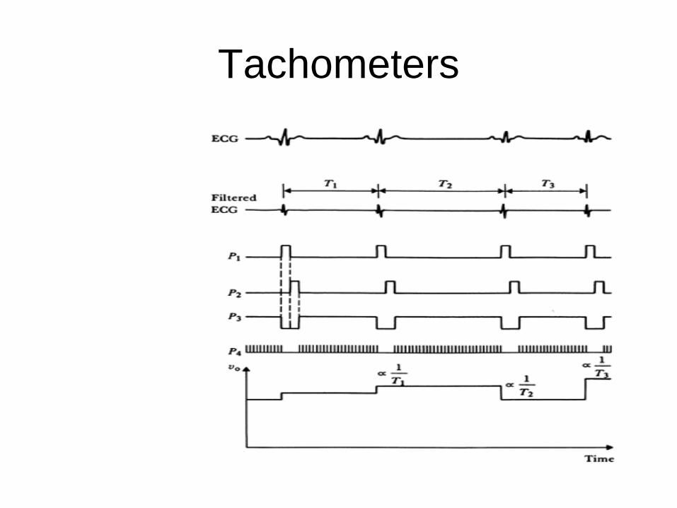
Tachometers
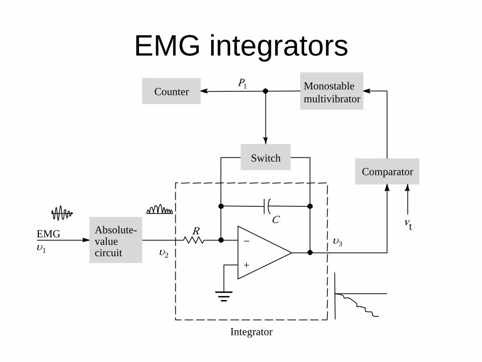
EMG integrators
Switch
Absolute-valuecircuit
Monostablemultivibrator
Comparator
CEMG
Integrator
−
+
R
P1
vt
υ1
Counter
υ2
υ3
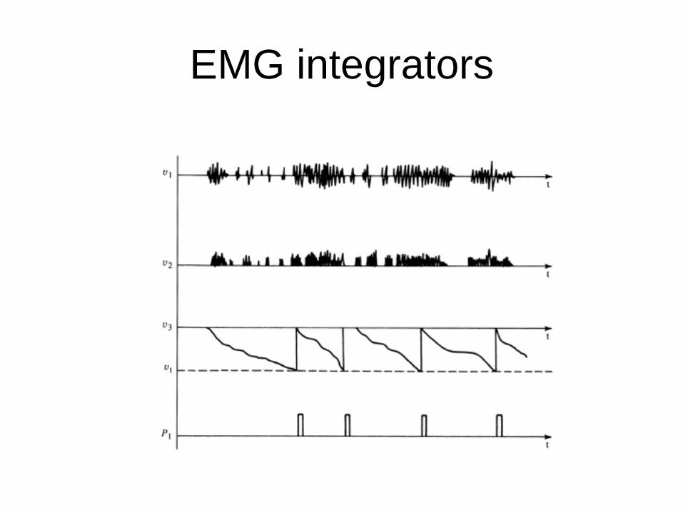
EMG integrators
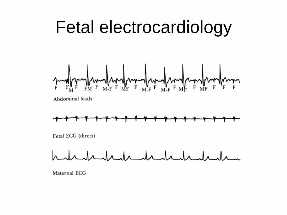
Fetal electrocardiology
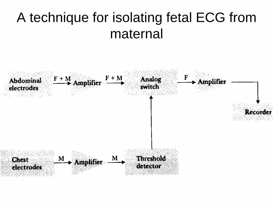
A technique for isolating fetal ECG from maternal
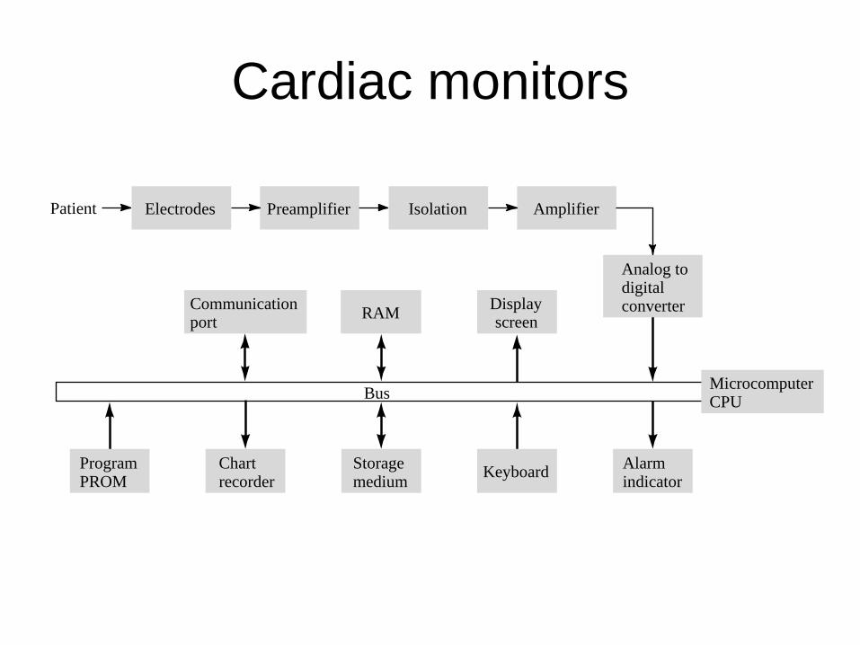
Cardiac monitors
Patient
Bus
Electrodes Preamplifier
RAM Displayscreen
Isolation Amplifier
ProgramPROM
Chartrecorder
Storagemedium Keyboard Alarm
indicator
Analog todigitalconverter
MicrocomputerCPU
Communicationport
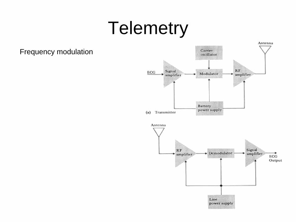
Telemetry Frequency modulation
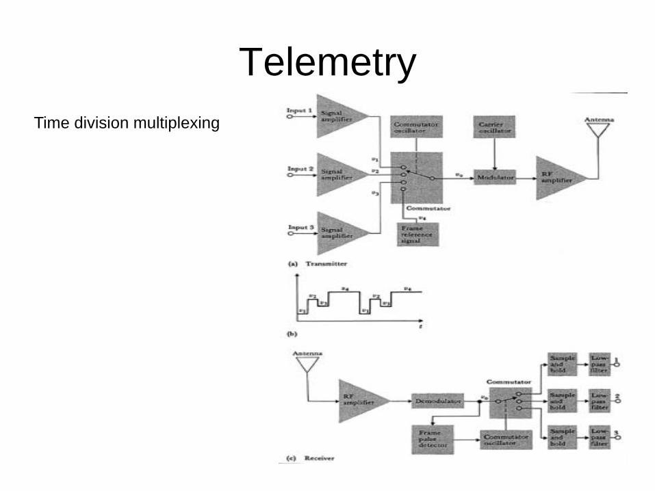
TelemetryTime division multiplexing

Digital landline telemetry system
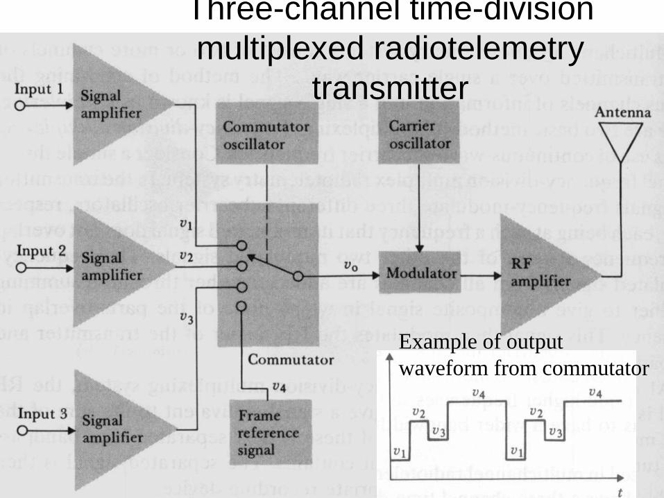
Three-channel time-division multiplexed radiotelemetry
transmitter
Example of output waveform from commutator
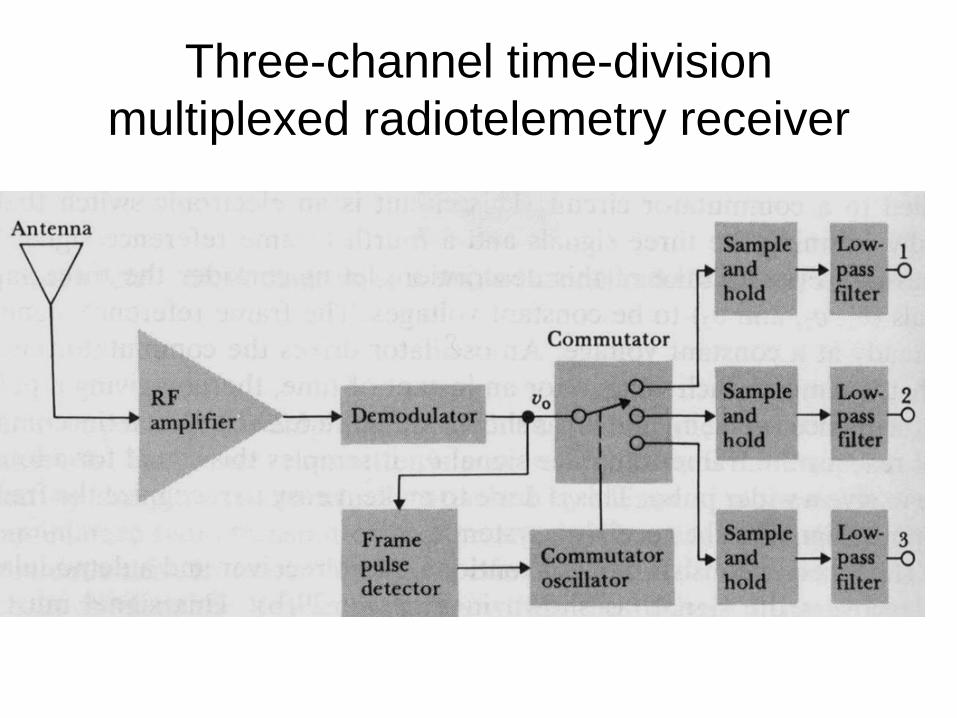
Three-channel time-division multiplexed radiotelemetry receiver
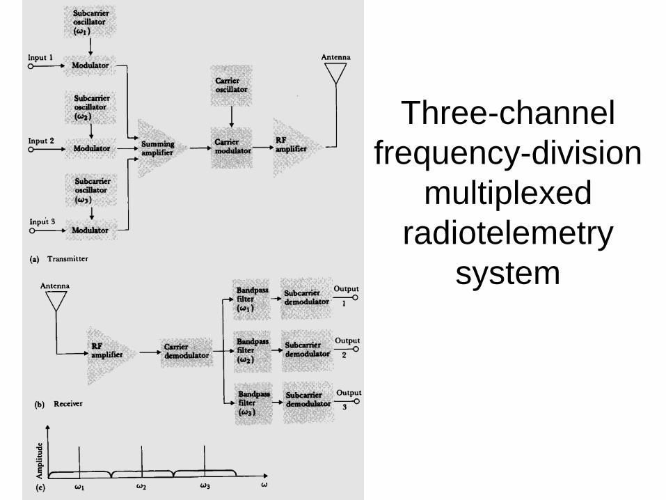
Three-channel frequency-division
multiplexed radiotelemetry
system
Recommended