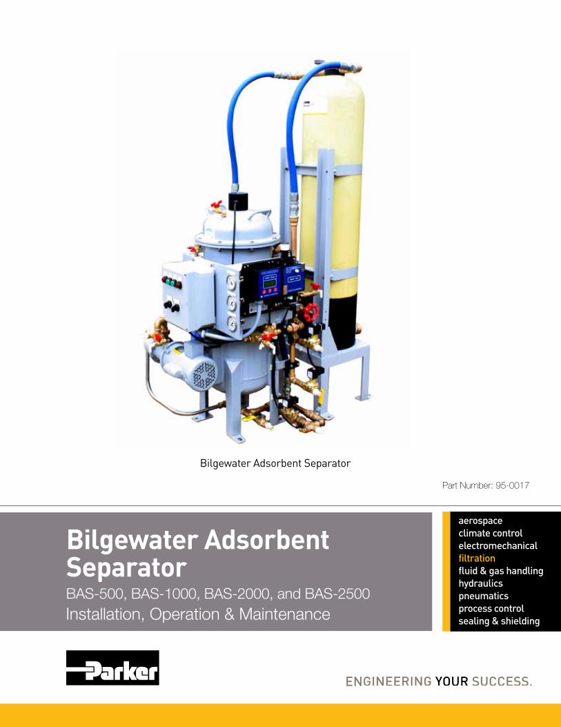
Bilgewater Adsorbent SeparatorBAS-500, BAS-1000, BAS-2000, and BAS-2500Installation, Operation & Maintenance
Bilgewater Adsorbent Separator
Part Number: 95-0017

TABLE OF CONTENTS
iii VMT REV -, JULY 2011
1.0 INTRODUCTION 5
1.1 UNPACKING AND HANDLING 6
1.2 PERFORMANCE SPECIFICATIONS 6
1.3 PHYSICAL CHARACTERISTICS 6
1.4 UTILITY REQUIREMENTS 6
1.5 ENVIRONMENTAL REQUIREMENTS 7
2.0 INSTALLATION 7
2.1 LOCATION FOR BAS 7
2.2 TO INSTALL THE BAS 7
2.3 ASSEMBLING THE MEDIA TANK 9
2.4 MEDIA CONDITIONING 10
2.4 TO CONNECT THE ELECTRICAL 12
3.0 GENERAL THEORY OF OPERATION 13
3.1 THEORY OF OPERATION 13
3.2 OPERATIONAL DESCRIPTION 14
3.3 OIL DISCHARGE MODE 14
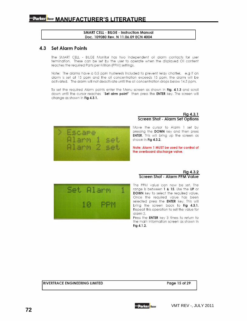
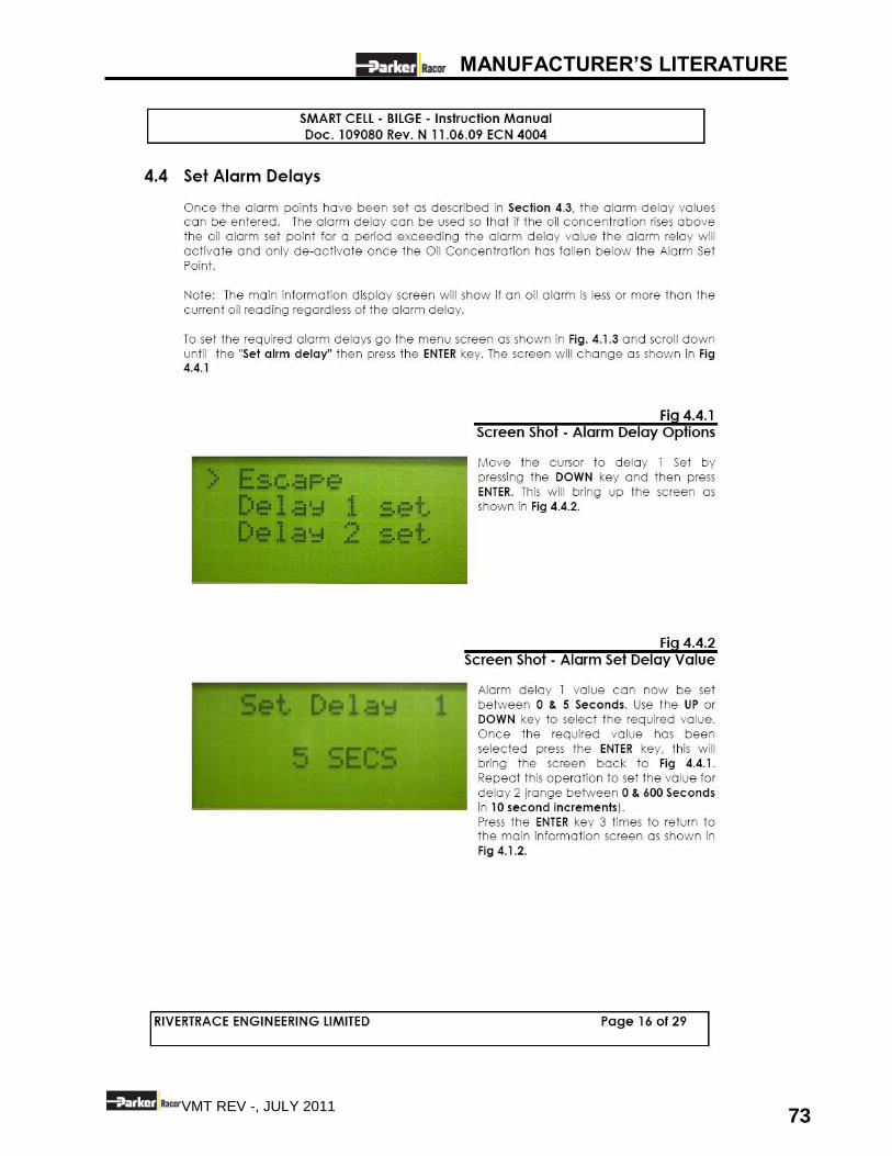
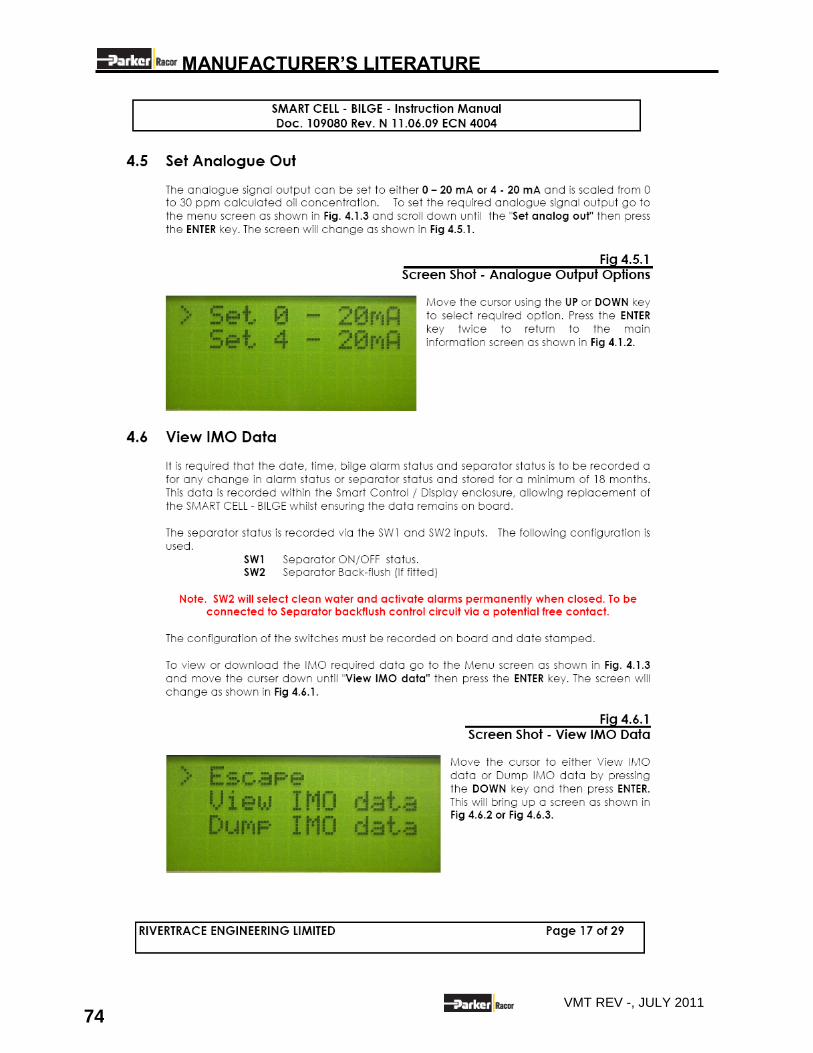
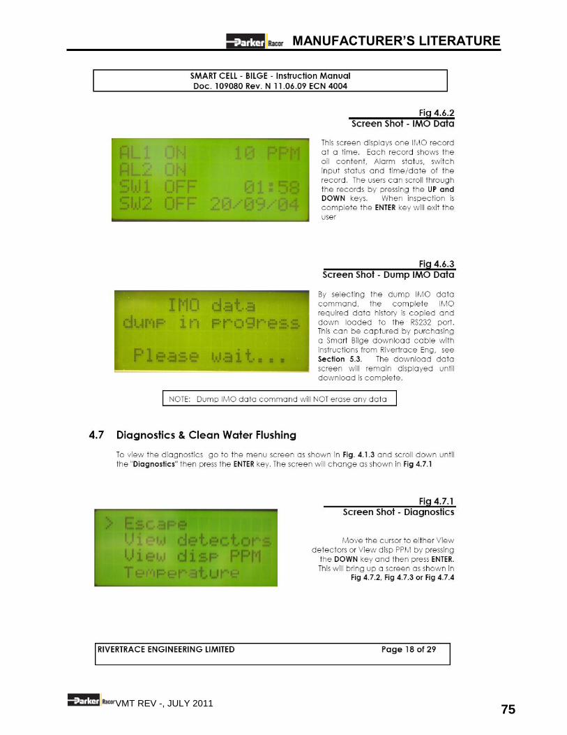
3.4 CONTROL PANEL 15
3.5 CONTROLS AND INSTRUMENTATION 16
4.0 OPERATION 17
4.1 TO START THE BAS 18
4.2 NORMAL OPERATION 19
4.3 BACKFLUSHING THE MEDIA 20
4.4 TO SHUT DOWN UNIT 21
4.4 MAINTENANCE SHUTDOWN 22
5.0 MAINTENANCE 23
5.1 PUMP MOTOR LUBRICATION 23
TABLE OF CONTENTS
iv VMT REV -, JULY 2011
5.2 CLEANING THE BAS UNIT 25
5.3 PRE-FILTER REPLACEMENT 25
6.0 DISASSEMBLY AND REPAIR 27
6.1 SCOPE 27
6.2 SEPARATION MEDIA REPLACEMENT 27
6.3 LEVEL CONTROL RELAY REPLACEMENT 27
6.4 FEED PUMP REPAIR 28
7.0 TROUBLESHOOTING 32
8.0 DRAWINGS AND DIAGRAMS 35
9.1 SPARES AND CONSUMABLES 41
9.2 SPARES-OIL CONTENT MONITOR (SMART CELL-BILGE) 41
10.0 MANUFACTURER’S LITERATURE 57
10.1 SMART CELL- BILGE- INSTRUCTION MANUAL 57
10.2 PROGRESSIVE CAVITY PUMP SPARE PARTS 57
10.3 CERTIFICATES 57
INSTALLATION
5 VMT REV -, JULY 2011
1.0 INTRODUCTION SYSTEM DESCRIPTION
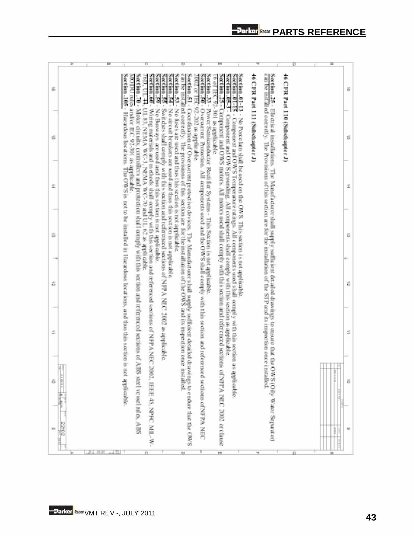
Parker Racor Village Marine Tec’s (VMT) Bilgewater Adsorbent Separators, hereafter referred to as (BAS), have been designed to meet the International Maritime Organization (IMO) resolution MEPC107 (49). (Guidelines and Specifications for Pollution Prevention Equipment for Machinery Space Bilges of Ships) as incorporated into 46 CFR 162.050. The VMT units are an advanced three -stage system capable of handling the complete range of oils that might be carried on board a commercial marine vessel.
HOW TO USE YOUR MANUAL This User Guide & Reference Manual contains important information about the safe operation and maintenance of your Bilgewater Adsorbent Separator unit. We advise you to please read through the entire User Guide & Reference Manual carefully to ensure you familiarize yourself with the operation of your BAS system and follow the recommendations within the manual, to help make your water purification experience trouble-free and enjoyable.
SAFETY WARNINGS Throughout this User Guide & Reference Manual you will see many important statements or labels indicated on the product with the following words:
Indicates a strong possibility of severe personal injury or death if warning instructions are ignored.
Indicates hazards or unsafe practices of product may cause minor personal injury or may cause property damage.
NOTE: Text specifies useful information.
INSTALLATION
6 VMT REV -, JULY 2011
1.1 UNPACKING AND HANDLING The Bilgewater Adsorbent Separator (BAS) is shipped pre-assembled. There are no special instructions towards unpacking and handling of the watermaker system. Inspect the BMS unit to verify it was not damaged in transit. Be sure to mark and record all hose locations for reference, if disconnection of hoses becomes necessary. DO NOT EXPOSE THE BILGEWATER ADSORBENT SEPARATOR UNIT TO FREEZING TEMPERATURES WITHOUT PROPER STEPS TO TREAT THE UNIT FOR SUB-FREEZING TEMPERATURES.
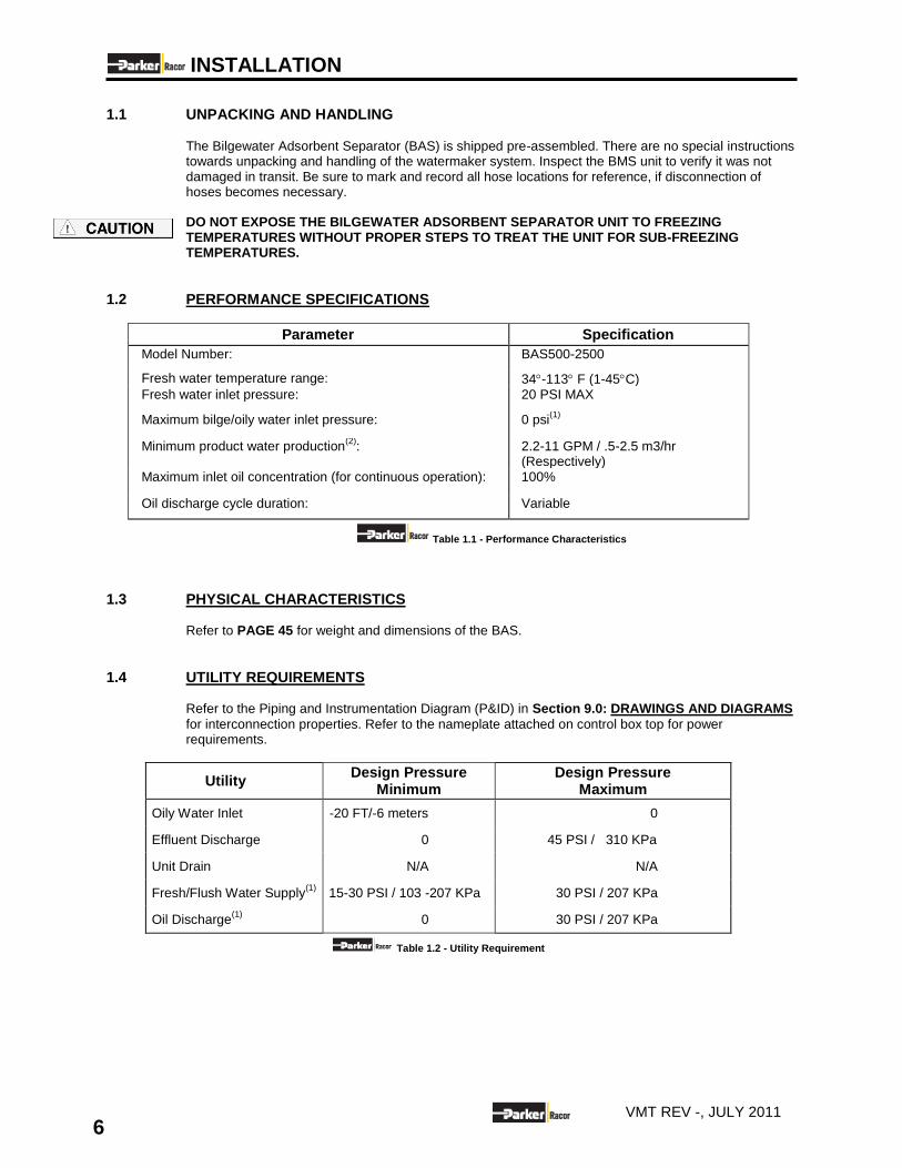
1.2 PERFORMANCE SPECIFICATIONS
Parameter Specification
Model Number: BAS500-2500
Fresh water temperature range: 34-113 F (1-45C) Fresh water inlet pressure: 20 PSI MAX
Maximum bilge/oily water inlet pressure: 0 psi(1)
Minimum product water production(2)
: 2.2-11 GPM / .5-2.5 m3/hr (Respectively)
Maximum inlet oil concentration (for continuous operation): 100%
Oil discharge cycle duration: Variable
Table 1.1 - Performance Characteristics
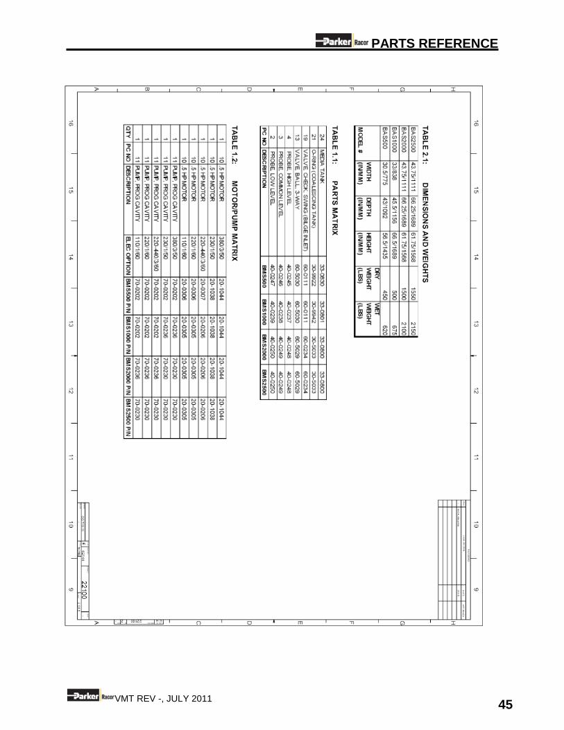
1.3 PHYSICAL CHARACTERISTICS Refer to PAGE 45 for weight and dimensions of the BAS.
1.4 UTILITY REQUIREMENTS Refer to the Piping and Instrumentation Diagram (P&ID) in Section 9.0: DRAWINGS AND DIAGRAMS
for interconnection properties. Refer to the nameplate attached on control box top for power requirements.
Utility Design Pressure
Minimum Design Pressure
Maximum
Oily Water Inlet -20 FT/-6 meters 0
Effluent Discharge 0 45 PSI / 310 KPa
Unit Drain N/A N/A
Fresh/Flush Water Supply(1)
15-30 PSI / 103 -207 KPa 30 PSI / 207 KPa
Oil Discharge(1)
0 30 PSI / 207 KPa
Table 1.2 - Utility Requirement
INSTALLATION
7 VMT REV -, JULY 2011
1.5 ENVIRONMENTAL REQUIREMENTS
Parameter Specifications Ambient Temperature Range 34-113F (1-45C)
Pitch: 22 (6 sec cycle)
Roll: 22 (12 sec cycle)
Table 1.3 - Nominal Operating Conditions
2.0 INSTALLATION
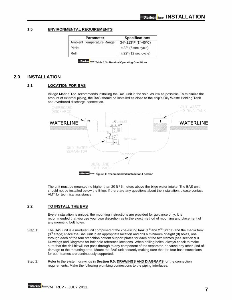
2.1 LOCATION FOR BAS
Village Marine Tec. recommends installing the BAS unit in the ship, as low as possible. To minimize the amount of external piping, the BAS should be installed as close to the ship’s Oily Waste Holding Tank and overboard discharge connection.
Figure 1: Recommended Installation Location
The unit must be mounted no higher than 20 ft / 6 meters above the bilge water intake. The BAS unit should not be installed below the Bilge. If there are any questions about the installation, please contact VMT for technical assistance.
2.2 TO INSTALL THE BAS Every installation is unique, the mounting instructions are provided for guidance only. It is recommended that you use your own discretion as to the exact method of mounting and placement of any mounting bolt holes.
Step 1: The BAS unit is a modular unit comprised of the coalescing tank (1st and 2
nd Stage) and the media tank
(3rd
stage).Place the BAS unit in an appropriate location and drill a minimum of eight (8) holes, one through each of the four stanchion bottom support plates for each of the two frames (see section 9.0 Drawings and Diagrams for bolt hole reference locations. When drilling holes, always check to make sure that the drill bit will not pass through to any component of the separator, or cause any other kind of damage to the mounting area. Mount the BAS unit securely making sure that the four base stanchions for both frames are continuously supported.
Step 2: Refer to the system drawings in Section 9.0: DRAWINGS AND DIAGRAMS for the connection
requirements. Make the following plumbing connections to the piping interfaces:
WATERLINEWATERLINE
INSTALLATION
8 VMT REV -, JULY 2011
A FOOT VALVE AND STRAINER MUST BE INSTALLED BY THE CONSUMER TO PREVENT FOREIGN MATERIAL OBSTRUCTING AND CLOGGING THE BAS. FAILURE TO INSTALL A FOOT VALVE WITH A SUITABLE STRAINER MAY VOID THE BAS SYSTEM WARRANTY.
Connect the oily water inlet line to the check valve located on the left side of the unit when facing the control panel (see Table 1.2 for raw water utility requirements). The inlet piping should at least equal in size to the inlet connection size. A foot valve and strainer must be installed at the end of the inlet piping where it takes suction from the bilge. INLET AND DISCHARGE INTERCONNECTING LINES SHOULD BE CONSTRUCTED OF SUITABLE MATERIAL. PLASTIC MATERIALS SUCH AS PVC MAY NOT BE SUITABLE DUE TO THEIR INCOMPATIBILITY WITH CERTAIN FUELS AND OILS.
NOTE: Verify all piping connections are airtight. Excessive air in solution with the clean water effluent results in erroneous high oil content readings. A) Connect the overboard discharge (SOV-2) to a 3 way manual recirculation valve (3-way ball
valve). The clean water discharge connection is ¾” HB and is located in the back side of the BAS (when facing the control panel). Connect one side of the 3-way ball valve to your desired connection for overboard discharge. The overboard discharge port may be located above or below the waterline provided that there is no back pressure. Connect the other side of the 3-way ball valve back to the bilge.
NOTE: For future inspection purposes on board ship, a sampling point should be provided in a vertical section of the water effluent piping as close as is practicable to the 15ppm Bilge Separator outlet. A manual re-circulate valve MUST be installed, after and adjacent to the overboard outlet of the stopping device (SOV2-clean water discharge solenoid valve) to enable the 15ppm Bilge Separator system, including the 15ppm Bilge Alarm and the automatic stopping device, to be tested with the overboard discharge closed. (See P&ID 22101 in Drawings and Diagrams) B) Connect the oil discharge to an unobstructed ¾” line that is connected to the top of the oily waste
storage tank. The oil discharge connection is ¾" HB and is located on the back side of the unit (when facing the control panel) near the top.
NOTE: If the discharge of water into the waste oil tank is unacceptable, a line must be installed to
manually divert the oil discharge link back to the bilge when cleaning.
C) Connect a fresh water source to the ¾" flush water supply line. This connection is ¾" HB and is
connected at the Fresh Water Solenoid Valve (SOV1) located in the back of the unit when facing the control panel.
D) Connect the recirculation line (SOV3) to an unobstructed ¾” line that is connected back to the
bilge. SOV3 will open when the oil content is above 15ppm at which point all effluent will be directed back to the bilge.
E) Connect the backflush line (V6) to an unobstructed ¾” line that is connected back to the bilge. The
flush line is ¾” HB and is located on the left side of the unit (when facing the control panel). Please refer to section 9 drawings and diagrams for locations.
F) Connect all drains back to bilge. DO NOT CONNECT THE SYSTEM DRAIN LINES TO THE CLEAN WATER EFFLUENT PIPING AS WATER DRAINED FROM THE SEPARATOR MAY HAVE RESIDUAL OIL LEVELS GREATER THAN 15 PPM.
INSTALLATION
9 VMT REV -, JULY 2011
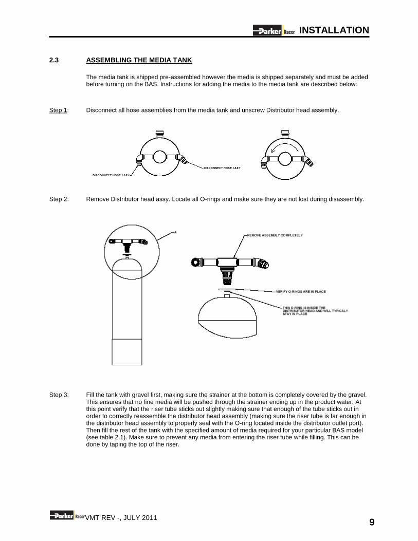
2.3 ASSEMBLING THE MEDIA TANK
The media tank is shipped pre-assembled however the media is shipped separately and must be added before turning on the BAS. Instructions for adding the media to the media tank are described below:
Step 1: Disconnect all hose assemblies from the media tank and unscrew Distributor head assembly.
Step 2: Remove Distributor head assy. Locate all O-rings and make sure they are not lost during disassembly.
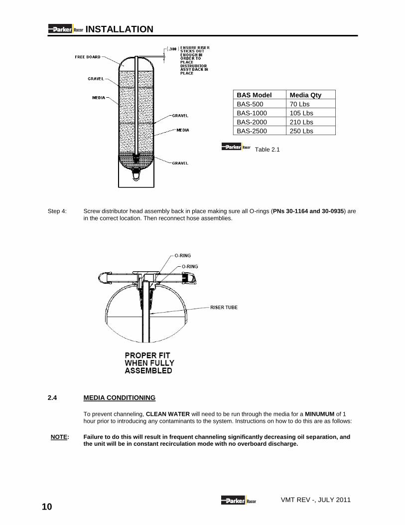
Step 3: Fill the tank with gravel first, making sure the strainer at the bottom is completely covered by the gravel.
This ensures that no fine media will be pushed through the strainer ending up in the product water. At this point verify that the riser tube sticks out slightly making sure that enough of the tube sticks out in order to correctly reassemble the distributor head assembly (making sure the riser tube is far enough in the distributor head assembly to properly seal with the O-ring located inside the distributor outlet port). Then fill the rest of the tank with the specified amount of media required for your particular BAS model (see table 2.1). Make sure to prevent any media from entering the riser tube while filling. This can be done by taping the top of the riser.
INSTALLATION
10 VMT REV -, JULY 2011
Table 2.1 Step 4: Screw distributor head assembly back in place making sure all O-rings (PNs 30-1164 and 30-0935) are
in the correct location. Then reconnect hose assemblies.
2.4 MEDIA CONDITIONING
To prevent channeling, CLEAN WATER will need to be run through the media for a MINUMUM of 1
hour prior to introducing any contaminants to the system. Instructions on how to do this are as follows:
NOTE: Failure to do this will result in frequent channeling significantly decreasing oil separation, and
the unit will be in constant recirculation mode with no overboard discharge.
BAS Model Media Qty
BAS-500 70 Lbs
BAS-1000 105 Lbs
BAS-2000 210 Lbs
BAS-2500 250 Lbs
INSTALLATION
11 VMT REV -, JULY 2011
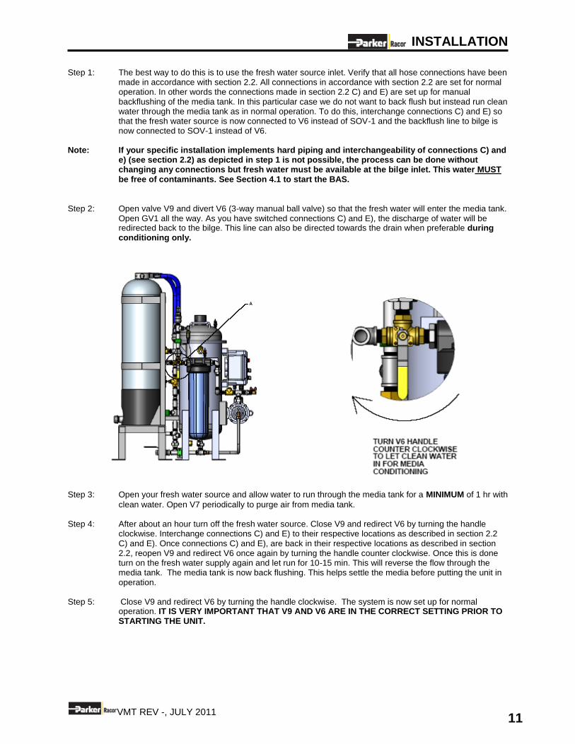
Step 1: The best way to do this is to use the fresh water source inlet. Verify that all hose connections have been made in accordance with section 2.2. All connections in accordance with section 2.2 are set for normal operation. In other words the connections made in section 2.2 C) and E) are set up for manual backflushing of the media tank. In this particular case we do not want to back flush but instead run clean water through the media tank as in normal operation. To do this, interchange connections C) and E) so that the fresh water source is now connected to V6 instead of SOV-1 and the backflush line to bilge is now connected to SOV-1 instead of V6.
Note: If your specific installation implements hard piping and interchangeability of connections C) and
e) (see section 2.2) as depicted in step 1 is not possible, the process can be done without changing any connections but fresh water must be available at the bilge inlet. This water MUST be free of contaminants. See Section 4.1 to start the BAS.
Step 2: Open valve V9 and divert V6 (3-way manual ball valve) so that the fresh water will enter the media tank.
Open GV1 all the way. As you have switched connections C) and E), the discharge of water will be redirected back to the bilge. This line can also be directed towards the drain when preferable during conditioning only.
Step 3: Open your fresh water source and allow water to run through the media tank for a MINIMUM of 1 hr with
clean water. Open V7 periodically to purge air from media tank. Step 4: After about an hour turn off the fresh water source. Close V9 and redirect V6 by turning the handle
clockwise. Interchange connections C) and E) to their respective locations as described in section 2.2 C) and E). Once connections C) and E), are back in their respective locations as described in section 2.2, reopen V9 and redirect V6 once again by turning the handle counter clockwise. Once this is done turn on the fresh water supply again and let run for 10-15 min. This will reverse the flow through the media tank. The media tank is now back flushing. This helps settle the media before putting the unit in operation.
Step 5: Close V9 and redirect V6 by turning the handle clockwise. The system is now set up for normal
operation. IT IS VERY IMPORTANT THAT V9 AND V6 ARE IN THE CORRECT SETTING PRIOR TO STARTING THE UNIT.
INSTALLATION
12 VMT REV -, JULY 2011
2.4 TO CONNECT THE ELECTRICAL
TURN OFF ALL ELECTRICAL POWER FOR USE WITH THE BAS UNIT PRIOR TO CONNECTING TO THE BAS POWER SOURCE. FAILURE TO DO SO MAY RESULT IN SERIOUS INJURY OR DEATH TO PERSONS HANDLING THE UNIT.
NOTE: Adhere to all electrical codes and regulations governing the installation and wiring of electrical
equipment. Typical codes specify the type and size of conduit, wire diameter, and class or wire insulation depending upon the amperage and environment.
NOTE: The power supply should always be of greater service rating than the requirements of the BAS
unit. This will assure proper voltage even if power supply voltage is slightly less than required. Never connect the BAS unit to a line that services another electrical device. THE BAS UNIT SHOULD HAVE ITS OWN INDEPENDENT POWER SUPPLY.
Step 1: Connect the correct voltage/power supply. Step 2: Connect a suitable ground to the BAS unit skid (as determined by the specifics of your installation).

GENERAL THEORY
13 VMT REV -, JULY 2011
3.0 GENERAL THEORY OF OPERATION
3.1 THEORY OF OPERATION
The VMT units are an advanced three -stage system capable of handling the complete range of oils that might be carried on board a commercial marine vessel. STAGE 1: The first or Separator stage consists of a coalescing tank described below: Oil and water do not mix easily. Given enough time to elapse, a static mixture of oil and water will almost separate on its own. There are special proprietary filtration polymers that VMT employs which have strong affinities for oil. The design and construction of the VMT BMS takes maximum advantage of both of these principles in order to reduce effluent oil concentrations in the overboard discharged water to less than 15 parts per million (ppm). To minimize oily and water mixing or agitation, the feed pump is placed on the downstream side of the coalescing tank. This minimizes the agitation on the inlet stream which reduces emulsified oil (i.e. suspended in the water as a solution) amounts, increasing the overall 1
ST stage efficiency of the VMT
separation process. Upon entering the Separator Stage, the oily water enters a large diameter first-pass chamber, reducing its stream velocity. Decelerating the oily water stream is critical; it maximizes the amount of time for gravity separation to take place. The slower the stream velocity, the longer the oily water will be in contact with the VMT filtration media. The first-pass chamber is filled with specially designed proprietary polyethylene rings that have a high surface-area-to-weight ratio. As the oily water flows along the surface of the polyethylene rings, small droplets will adhere to its surface. When enough has collected, the oil droplets’ natural buoyancy will cause them to release and float to the separator top, when enough oil collects at the top, the unit automatically back-flushes the accumulated oil out of the unit and into a waste holding tank. STAGE 2: Prior to exiting the coalescing tank, the reduced concentration oily water mixture passes through a polishing chamber. This chamber is completely filled with tightly packed polypropylene beads that are designed to remove any remaining free oil from the effluent stream. This unique design ensures the effluent discharge is less than 15 ppm of free oil. STAGE 3: Under IMO resolution MEPC107 (49), all Bilgewater Separators must be able to handle the complete range of oils that might be carried on board ship, whether they are free oils or in emulsion. The coalescing tank is effective in separating free oils but is unable to handle emulsions, which is why the (Third) stage of the BAS is implemented specifically to treat emulsified oils. This is done through the use of organic clays which are capable of adsorbing oil in emulsion. The effluent from the Separator stage coalescing tank is pressurized by the feed pump for processing through the Parker pre filter. The filter removes suspended solids and oil droplets of approximately 5 microns and larger from the flow. This semi cleaned effluent is passed through the third stage which is a media tank containing organic clays capable of adsorbing emulsified oil. The process is maximized through careful engineering creating desirable conditions of feed flow, contact time, and bed depth. All processed water is continuously monitored by an MEPC107 (49) approved Oil Content Meter (Smart Cell) before the water is discharged overboard. If the oil content exceeds 15 ppm, this “bad” water will automatically be redirected to the vessel’s bilge beginning the process again.
GENERAL THEORY
14 VMT REV -, JULY 2011
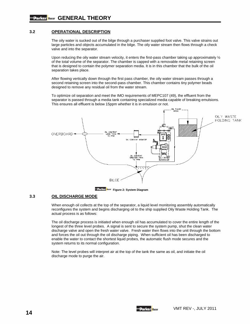
3.2 OPERATIONAL DESCRIPTION The oily water is sucked out of the bilge through a purchaser supplied foot valve. This valve strains out large particles and objects accumulated in the bilge. The oily water stream then flows through a check valve and into the separator. Upon reducing the oily water stream velocity, it enters the first-pass chamber taking up approximately ½ of the total volume of the separator. The chamber is capped with a removable metal retaining screen that is designed to contain the polymer separation media. It is in this chamber that the bulk of the oil separation takes place. After flowing vertically down through the first pass chamber, the oily water stream passes through a second retaining screen into the second-pass chamber. This chamber contains tiny polymer beads designed to remove any residual oil from the water stream. To optimize oil separation and meet the IMO requirements of MEPC107 (49), the effluent from the separator is passed through a media tank containing specialized media capable of breaking emulsions. This ensures all effluent is below 15ppm whether it is in emulsion or not.
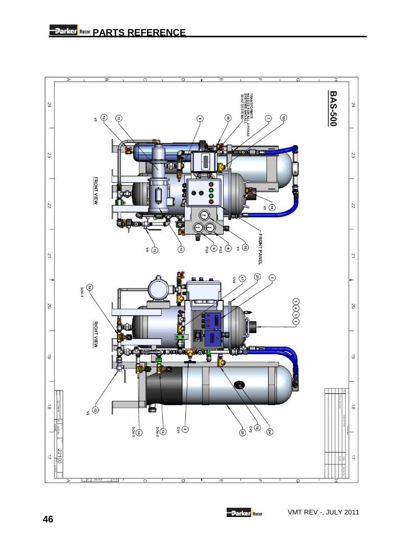
Figure 2: System Diagram
3.3 OIL DISCHARGE MODE When enough oil collects at the top of the separator, a liquid level monitoring assembly automatically reconfigures the system and begins discharging oil to the ship supplied Oily Waste Holding Tank. The actual process is as follows: The oil discharge process is initiated when enough oil has accumulated to cover the entire length of the longest of the three level probes. A signal is sent to secure the system pump, shut the clean water discharge valve and open the fresh water valve. Fresh water then flows into the unit through the bottom and forces the oil out through the oil discharge piping. When sufficient oil has been discharged to enable the water to contact the shortest liquid probes, the automatic flush mode secures and the system returns to its normal configuration. Note: The level probes will interpret air at the top of the tank the same as oil, and initiate the oil discharge mode to purge the air.
GENERAL THEORY
15 VMT REV -, JULY 2011
3.4 CONTROL PANEL The BAS is equipped with a centralized control panel for monitoring of all important unit functions and operating parameters. The specific control switches and status (indicating) lights utilized are as follows: CONTROL SWITCHES
(1) ON/OFF CONTROL SWITCH
Controls the operation (ON/OFF) of the entire system. Placing the switch in the "OFF" position prevents all operation of the system regardless of the position of all other switches.
(2) OPERATION SWITCH
Three position switch that controls system. System has an Auto mode (for normal operation) and a manual mode used for manual flushing. (MANUAL/OFF/AUTO)
(A) MANUAL
Immediately reconfigures system and activates oil discharge mode regardless of oil level. Unit will remain in oil discharge mode as long as the switch is placed in the “OFF” position. Used to prime system at start up. Afterwards this is used to manually flush the coalescing tank.
(B) AUTO
Activates BAS normal operating mode, effluent water discharge/ recirculation, oil discharge, cycles are all automated in normal operation.
STATUS (INDICATING LIGHTS)
(3) CLEAN WATER DISCHARGE LIGHT
GREEN light illuminates whenever the unit is operating in its normal mode and is discharging clean effluent.
(4) OIL DISCHARGE LIGHT
GREEN light illuminates whenever the unit is operating in the Oil Discharge mode and is discharging either oil or fresh water through the oil discharge line.
(6) POWER ON LIGHT
RED light illuminates whenever the unit is receiving the power necessary for operation. This light will illuminate regardless of whether the unit is actually operating.
(7) ALARM 1 LIGHT
RED light illuminates whenever PSW1 detects low pressure downstream of the pre filter indicating filter replacement may be required.
GENERAL THEORY
16 VMT REV -, JULY 2011
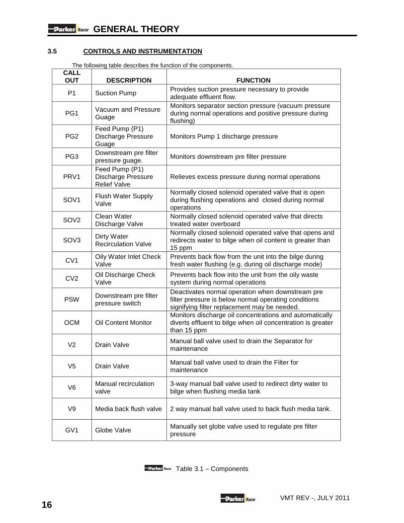
3.5 CONTROLS AND INSTRUMENTATION The following table describes the function of the components.
CALL OUT DESCRIPTION FUNCTION
P1 Suction Pump Provides suction pressure necessary to provide adequate effluent flow.
PG1 Vacuum and Pressure Guage
Monitors separator section pressure (vacuum pressure during normal operations and positive pressure during flushing)
PG2 Feed Pump (P1) Discharge Pressure Guage
Monitors Pump 1 discharge pressure
PG3 Downstream pre filter pressure guage.
Monitors downstream pre filter pressure
PRV1 Feed Pump (P1) Discharge Pressure Relief Valve
Relieves excess pressure during normal operations
SOV1 Flush Water Supply Valve
Normally closed solenoid operated valve that is open during flushing operations and closed during normal operations
SOV2 Clean Water Discharge Valve
Normally closed solenoid operated valve that directs treated water overboard
SOV3 Dirty Water Recirculation Valve
Normally closed solenoid operated valve that opens and redirects water to bilge when oil content is greater than 15 ppm
CV1 Oily Water Inlet Check Valve
Prevents back flow from the unit into the bilge during fresh water flushing (e.g. during oil discharge mode)
CV2 Oil Discharge Check Valve
Prevents back flow into the unit from the oily waste system during normal operations
PSW Downstream pre filter pressure switch
Deactivates normal operation when downstream pre filter pressure is below normal operating conditions signifying filter replacement may be needed.
OCM Oil Content Monitor Monitors discharge oil concentrations and automatically diverts effluent to bilge when oil concentration is greater than 15 ppm
V2 Drain Valve Manual ball valve used to drain the Separator for maintenance
V5 Drain Valve Manual ball valve used to drain the Filter for maintenance
V6 Manual recirculation valve
3-way manual ball valve used to redirect dirty water to bilge when flushing media tank
V9 Media back flush valve 2 way manual ball valve used to back flush media tank.
GV1 Globe Valve Manually set globe valve used to regulate pre filter pressure
Table 3.1 – Components
OPERATION
17 VMT REV -, JULY 2011
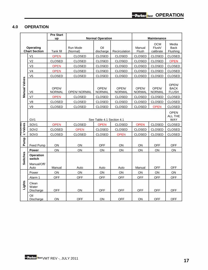
4.0 OPERATION
Operating Chart Section
Pre Start up Normal Operation Maintenance
Tank fill Run Mode (Normal)
Oil discharge Recirculation
Manual Flush
OCM Flush/
calibrate
Media Back
Flushing
Ma
nu
al
Va
lve
s
V1 OPEN CLOSED CLOSED CLOSED CLOSED CLOSED CLOSED
V2 CLOSED CLOSED CLOSED CLOSED CLOSED CLOSED OPEN
V3 OPEN CLOSED CLOSED CLOSED CLOSED CLOSED CLOSED
V4 OPEN CLOSED CLOSED CLOSED CLOSED CLOSED CLOSED
V5 CLOSED CLOSED CLOSED CLOSED CLOSED CLOSED CLOSED
V6 OPEN/
NORMAL OPEN/ NORMAL OPEN/
NORMAL OPEN/
NORMAL OPEN/
NORMAL OPEN/
NORMAL
OPEN/ BACK
FLUSH
V7 OPEN CLOSED CLOSED CLOSED CLOSED CLOSED CLOSED
V8 CLOSED CLOSED CLOSED CLOSED CLOSED CLOSED CLOSED
V9 CLOSED CLOSED CLOSED CLOSED CLOSED OPEN CLOSED
GV1 See Table 4.1 Section 4.1
OPEN ALL THE
WAY
Au
tom
ati
c V
alv
es
SOV1 OPEN CLOSED OPEN CLOSED OPEN CLOSED CLOSED
SOV2 CLOSED OPEN CLOSED CLOSED CLOSED CLOSED CLOSED
SOV3 CLOSED CLOSED CLOSED OPEN CLOSED CLOSED CLOSED
Pu
mp
Feed Pump ON ON OFF ON ON OFF OFF
Sw
itc
he
s Power ON ON ON ON ON ON ON
Operation switch
Manual Auto Auto Auto Manual OFF OFF Manual/Off/ Auto
Lig
hts
Power ON ON ON ON ON ON ON
Alarm 1 OFF OFF OFF OFF OFF OFF OFF
Clean Water Discharge OFF ON OFF OFF OFF OFF OFF
Oil Discharge ON OFF ON OFF ON OFF OFF
OPERATION
18 VMT REV -, JULY 2011
4.1 TO START THE BAS NOTE: For the initial start-up, verify to first complete the system installation in accordance with Section
2.0: INSTALLATION. If the media has not been conditioned as explained in section 2.4 then it can still be conditioned using this procedure however the bilge inlet MUST CONTAIN CLEAN WATER with no contaminants while media conditioning is in process.
4.1.1 Tank Fill
Step 1: Put all manual ball valves in the position shown on chart. V1,V3, V4 and V7 are all open. All others
closed. Step 2: Turn Power switch on. Verify the POWER ON light illuminates.
Step 3: Open valve V2. Verify that V6 is turned all the way clockwise. The fresh water source should be open, if
not, open the fresh water source now. Step 4: Allow water to fill the system. When water begins to bleed from V7 close valve. Repeat for V4. Step 5: Monitor PG3, when PG3 reaches 20-30 psi close V2. Verify that pressure stays stable and does not
drop.
Step 5: Place the OPERATION SWITCH in the manual position. Step 6: Allow the Separator to fill. Once V1 begins to bleed, shut off valve. Repeat for V3. NOTE: If the discharge of water into the waste oil tank is unacceptable, a line must be installed to
manually divert the oil discharge line back to the bilge when on manual mode.
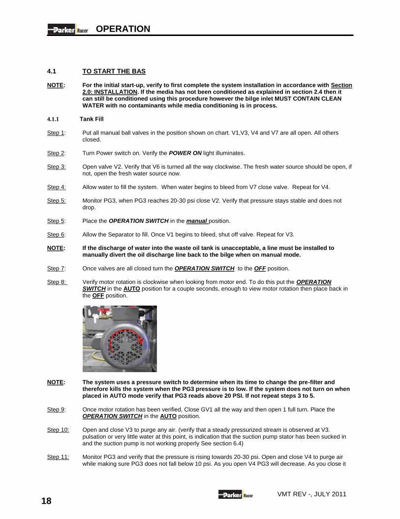
Step 7: Once valves are all closed turn the OPERATION SWITCH to the OFF position. Step 8: Verify motor rotation is clockwise when looking from motor end. To do this put the OPERATION
SWITCH in the AUTO position for a couple seconds, enough to view motor rotation then place back in the OFF position.
NOTE: The system uses a pressure switch to determine when its time to change the pre-filter and
therefore kills the system when the PG3 pressure is to low. If the system does not turn on when placed in AUTO mode verify that PG3 reads above 20 PSI. If not repeat steps 3 to 5.
Step 9: Once motor rotation has been verified, Close GV1 all the way and then open 1 full turn. Place the
OPERATION SWITCH in the AUTO position.
Step 10: Open and close V3 to purge any air. (verify that a steady pressurized stream is observed at V3.
pulsation or very little water at this point, is indication that the suction pump stator has been sucked in and the suction pump is not working properly See section 6.4)
Step 11: Monitor PG3 and verify that the pressure is rising towards 20-30 psi. Open and close V4 to purge air
while making sure PG3 does not fall below 10 psi. As you open V4 PG3 will decrease. As you close it
OPERATION
19 VMT REV -, JULY 2011
PG3 will increase. If pressure goes above 30 open GV1 to decrease pressure. Once the air is purged, close valve V4. Repeat for V7.
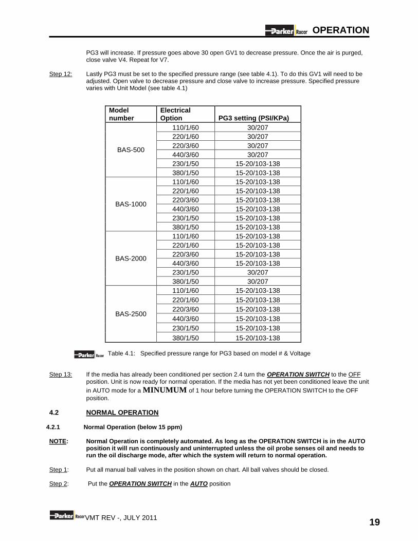
Step 12: Lastly PG3 must be set to the specified pressure range (see table 4.1). To do this GV1 will need to be
adjusted. Open valve to decrease pressure and close valve to increase pressure. Specified pressure varies with Unit Model (see table 4.1)
Model number
Electrical Option PG3 setting (PSI/KPa)
BAS-500
110/1/60 30/207
220/1/60 30/207
220/3/60 30/207
440/3/60 30/207
230/1/50 15-20/103-138
380/1/50 15-20/103-138
BAS-1000
110/1/60 15-20/103-138
220/1/60 15-20/103-138
220/3/60 15-20/103-138
440/3/60 15-20/103-138
230/1/50 15-20/103-138
380/1/50 15-20/103-138
BAS-2000
110/1/60 15-20/103-138
220/1/60 15-20/103-138
220/3/60 15-20/103-138
440/3/60 15-20/103-138
230/1/50 30/207
380/1/50 30/207
BAS-2500
110/1/60 15-20/103-138
220/1/60 15-20/103-138
220/3/60 15-20/103-138
440/3/60 15-20/103-138
230/1/50 15-20/103-138
380/1/50 15-20/103-138
Table 4.1: Specified pressure range for PG3 based on model # & Voltage
Step 13: If the media has already been conditioned per section 2.4 turn the OPERATION SWITCH to the OFF
position. Unit is now ready for normal operation. If the media has not yet been conditioned leave the unit
in AUTO mode for a MINUMUM of 1 hour before turning the OPERATION SWITCH to the OFF
position.
4.2 NORMAL OPERATION
4.2.1 Normal Operation (below 15 ppm) NOTE: Normal Operation is completely automated. As long as the OPERATION SWITCH is in the AUTO
position it will run continuously and uninterrupted unless the oil probe senses oil and needs to run the oil discharge mode, after which the system will return to normal operation.
Step 1: Put all manual ball valves in the position shown on chart. All ball valves should be closed. Step 2: Put the OPERATION SWITCH in the AUTO position
OPERATION
20 VMT REV -, JULY 2011
Step 4: Inspect unit for proper operation. Check PG3 and verify that it reads the specified pressure indicated in
table 4.1 per the applicable model #.
If pressure reading reads within the recommended pressure ranges unit is now operational. The water discharge light will be illuminated and the system will begin discharging overboard as long as
the ppm is <15ppm
NOTE: During first start up, when introducing bilge water into system there will be a media settling
period, which will cause the OIL CONTENT MONITOR alarm to trigger more frequently than normal. This will only happen at first start up. When Alarm triggers it will be necessary to perform a back flushing cycle on the media tank in order to re settle the media. (see Section 4.3)
4.2.2 Normal Operation Oil Discharge
When the Oil Sensing Probe (OSP) sees enough oil to discharge it will automatically do the following: 1. Shut off Feed Pump P1 2. Open SOV1 3. Close SOV2 and SOV3 4. The oil discharge light will illuminate 5. When all oil is discharged to the slop tank and the OSP sees clean water it will revert back to
normal operation.
4.2.3 Normal Operation (Over 15 ppm) Recirculation to Bilge
When the “Oil Content Monitor” (OCM) reads over 15 ppm the following happens automatically to prevent oil from being discharged overboard. 1. SOV2 (effluent discharge overboard) closes and SOV3 (recirculation to bilge) opens. 2. The overboard discharge light will go out. 3. Everything else remains the same as in normal operation
NOTE: When the OCM alarm is triggered back flushing will need to be performed per section 4.3 in order to resettle the media. In most cases this is due to channeling which can happen from time to time.
4.3 BACKFLUSHING THE MEDIA When the oil content alarm is triggered it will be due to one of two possible reasons. Either the media is completely exhausted and must be replaced or channeling has occurred. When channeling is the case simply perform a back flush for 10-15 min and then put the unit back in operation. The process for back flushing is as follows:
Step 1: Turn the OPERATION SWITCH to the OFF position. Step 2: Open GV1 all the way and open V9. Redirect V6 by turning the handle counter clockwise. Step 3: Let water run through media for 10-15 min. Step 4: Close V9 and redirect V6 by turning the handle clockwise. Step 5: Turn the OPERATION SWITCH to the AUTO position. Adjust GV1 and observe PG3 so that it reads the Specified pressure range according to the applicable model #. Step 6: Perform a Clean Water Flush on the Oil Content monitor per section 5.2.2
OPERATION
21 VMT REV -, JULY 2011
4.4 TO SHUT DOWN UNIT
NOTE: A system flush should be done prior to every shut down. This ensures that the system is clean
and prevents valves from sticking and also keeps the level probes clean, keeping the unit working properly.
Step 1: Place the OPERATION SWITCH in the MANUAL position. Step 2: Allow the flushing cycle to run for 10-15 min. NOTE: If the discharge of water into the waste oil tank is unacceptable, a line must be installed to
manually divert the oil discharge line back to the bilge while in manual mode (flushing).
Step 4: Place OPERATION SWITCH in the OFF position.
Step 5: System is ready for shut down. Place the OPERATION SWITCH in the OFF position. Step 6: Turn Power ON Switch in OFF position.
Step 7: Verify power on Light is off
OPERATION
22 VMT REV -, JULY 2011
4.4 MAINTENANCE SHUTDOWN
This procedure should be used if any system connections must be broken or the separator itself must be opened for maintenance.
Step 1: Perform shut down procedure as described in section 4.3
WATER DRAINED FROM THE SEPARATOR MAY HAVE RESIDUAL OIL LEVEL OF GREATER THAN 15 PPM. DO NOT DISCHARGE OVERBOARD IF WATER IS GREATER THAN 15 PPM. IT IS RECOMMENDED THAT THIS WATER BE DIRECTED BACK TO THE BILGE.
Step 2: Connect the BAS drain to a dedicated holding tank or bilge (if not connected during initial installation). NOTE: If holding tank is at level or above the BAS, use a boost pump to complete the system drain. NOTE: This procedure incorporates a gravity drain of the separator that will remove most, but not all of
the water from the separator.
Step 3: Once the BAS has been flushed and turned off, open drain valves V2, V6, V7 and V9 Step 4: When no more water flows from the drain connection, shut the drain valves.

MAINTENANCE
23 VMT REV -, JULY 2011
5.0 MAINTENANCE
5.1 PUMP MOTOR LUBRICATION
NOTE: Motors should be re-lubricated at least once a year.
Step 1: Locate the grease fittings near the motor shaft. Wipe the fitting clean. Step 2: Remove filler and drain plugs. Free drain hole of any hard grease if present (use a wire if necessary). Step 3: Add 2-3 strokes of grease using a low pressure grease gun (see Table 5.2 for grease type). Injecting
grease too quickly can cause untimely bearing malfunction. Inject grease slowly for approximately 1 minute.
Location Type
Pump Motor Chevron SRI Grease - NGLI 2 ExxonMobil PolyrexEM Grease Shell Oil Dolium R - NGLI 2 Texaco Premium RB
Table 5.2 - Motor and HP Pump Lubrication Requirements.
DO NOT mix grease types. Keep consistent the grade and type of grease used for motor. Also, keep the grease CLEAN.
Step 4: If the motor is equipped with a motor drain plug, replace the drain plug (if removed) and start BAS unit.
Let BAS to run motor for approximately 20 minutes. Step 5: Secure the BAS unit, wipe off any of the drained grease and replace the fill and drain plugs, as required.
The motor is now ready to resume operation.
MAINTENANCE
24 VMT REV -, JULY 2011
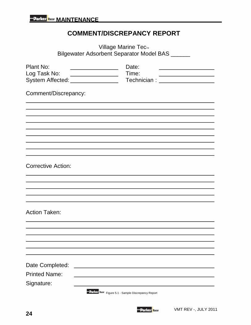
COMMENT/DISCREPANCY REPORT
Village Marine Tec Bilgewater Adsorbent Separator Model BAS ______
Plant No: Date: Log Task No: Time: System Affected: Technician : Comment/Discrepancy: Corrective Action: Action Taken: Date Completed:
Printed Name:
Signature:
Figure 5.1 - Sample Discrepancy Report
MAINTENANCE
25 VMT REV -, JULY 2011
5.2 CLEANING THE BAS UNIT
5.2.1 BAS Manual Flush
The coalescer tank media is cleaned by an upward flow of fresh water each time the oil discharge cycle starts. However if conditions have led to heavy loading of oil in the tank, extra cleaning can be done by running the oil discharge cycle manually for extra time or with hot water.
NOTE: If the discharge of water into the waste oil tank is unacceptable, a line must be installed to
manually divert the oil discharge link back to the bilge when flushing.
Step 1: Stop the system by placing the OPERATION SWITCH in the MANUAL position. This will initiate oil
discharge mode. If hot water 100F –150F (37C-65C) is available, it can be used for maximum cleaning.
Step 2: Allow the system to remain in oil discharge mode for approximately 20-30 minutes.
5.2.2 OCM Flush
NOTE: It is recommended that the OCM flush procedure be performed at least once a week, to prevent the OCM monitor from getting dirty and potentially reading false positives causing the system to remain in recirculation mode.
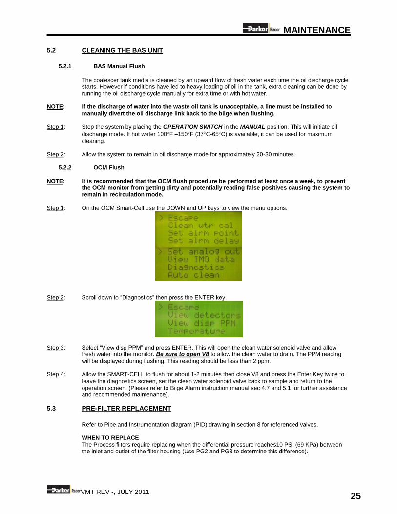
Step 1: On the OCM Smart-Cell use the DOWN and UP keys to view the menu options.
Step 2: Scroll down to “Diagnostics” then press the ENTER key.
Step 3: Select “View disp PPM” and press ENTER. This will open the clean water solenoid valve and allow
fresh water into the monitor. Be sure to open V8 to allow the clean water to drain. The PPM reading will be displayed during flushing. This reading should be less than 2 ppm.
Step 4: Allow the SMART-CELL to flush for about 1-2 minutes then close V8 and press the Enter Key twice to leave the diagnostics screen, set the clean water solenoid valve back to sample and return to the operation screen. (Please refer to Bilge Alarm instruction manual sec 4.7 and 5.1 for further assistance and recommended maintenance).
5.3 PRE-FILTER REPLACEMENT
Refer to Pipe and Instrumentation diagram (PID) drawing in section 8 for referenced valves. WHEN TO REPLACE
The Process filters require replacing when the differential pressure reaches10 PSI (69 KPa) between the inlet and outlet of the filter housing (Use PG2 and PG3 to determine this difference).
MAINTENANCE
26 VMT REV -, JULY 2011
FILTER REPLACEMENT PROCEDURE
Step 1: Place THE POWER switch in OFF position. Step 2: Verify the power on light is off. Step 3: Open valve V5 and drain the filter housing. Verify drain is connected back to bilge. Step 4: Once the filter housing is drained unscrew the filter housing from its cap which is bolted to the unit. Step 5: Locate cover O-ring and set aside for reassembly. Step 6: Install new filter element. Make sure filter gasket is firmly seated onto the step of the top of the filter before
reassembling. Step 7: Place cover O-ring back on top of housing and screw housing back to its cap. Step 5: Close the process filter drain valve V5. Step 6: Refill the system as described in section 4.1
DISASSEMBLY AND REPAIR
27 VMT REV -, JULY 2011
6.0 DISASSEMBLY AND REPAIR
6.1 SCOPE
This section provides instructions for removal, disassembly and repair of the Village Marine Tec Models BAS Bilgewater Adsorbent Separator and its components.
6.2 SEPARATION MEDIA REPLACEMENT
In normal and proper operation, the media will not require replacement. Periodic thorough cleaning can
be done by flushing with hot water (up to 150F). If media replacement is required due to special circumstances, then remove top hat and remove separation screen to remove media.
6.3 LEVEL CONTROL RELAY REPLACEMENT
Step 1: Turn off system by placing the POWER ON switch in the OFF position. Verify Power on light turns off.
Step 2: Place new level control relay in 11 pin plug. Make sure relay’s manufacturing print is right side up and
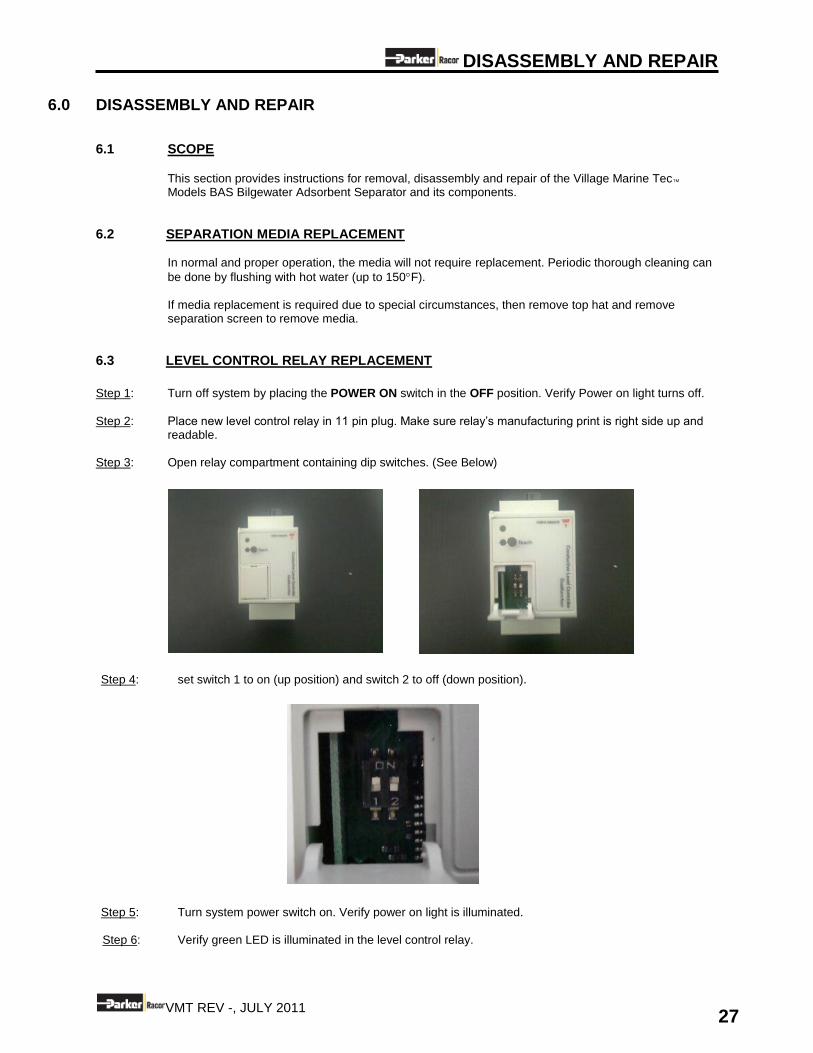
readable. Step 3: Open relay compartment containing dip switches. (See Below)
Step 4: set switch 1 to on (up position) and switch 2 to off (down position).
Step 5: Turn system power switch on. Verify power on light is illuminated. Step 6: Verify green LED is illuminated in the level control relay.
DISASSEMBLY AND REPAIR
28 VMT REV -, JULY 2011
Step 7: Make sure that the tank is full of water and that the probes are immersed. Press the “teach” pushbutton at the front of the controller for approximately 2 seconds, until the green LED turns OFF. The controller will now auto-adjust itself according to the resistance of the measuring liquid.
NOTE: If the resistance of the liquid is outside the maximum range handled by the controller, the green LED will flash quickly for a period of 2 seconds, indicating a wrong teach-in. If this occurs it probably means that the tank is full of oil. Flush the Tank per section 5.2.1 until only water is discharged.
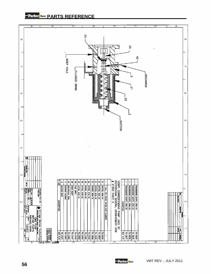
6.4 FEED PUMP REPAIR
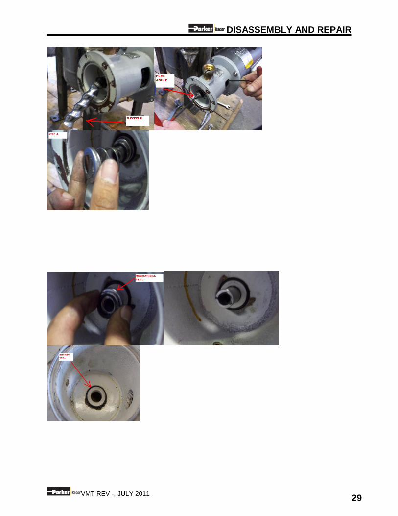
Pump Disassembly: Step 1 : Remove stator carefully. After removing it will be necessary to inspect all internal components for
damage. Step 2: Remove Rotor. Should be intact and in good working condition. Step 3: Remove flex joint. You will need to prevent the pump stub shaft from rotating in order to do this. Inspect
flex joint for damage. Replace if necessary. Step 4: Remove Spring tensioner. Inspect spring tensioner for damage. Replace if necessary Step 5: Remove Mechanical seal. Due this gently by pulling not squeezing. The Mechanical seal should come
off easily, minimal force is needed to remove this. This is the most fragile part of the internal assy. Check for damage.
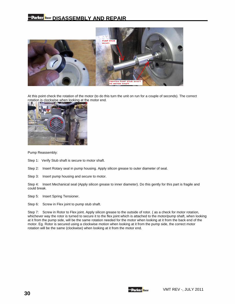
Step 6: Remove pump housing. You will notice the rotary seal will remain in the housing. Step 7: Remove the rotary seal. Check for damage. Replace if necessary. Step 8: Inspect Stub Shaft. This should be intact and in good working condition. Verify that the stub shaft is
secure to the motor shaft. .
DISASSEMBLY AND REPAIR
29 VMT REV -, JULY 2011
DISASSEMBLY AND REPAIR
30 VMT REV -, JULY 2011
At this point check the rotation of the motor (to do this turn the unit on run for a couple of seconds). The correct rotation is clockwise when looking at the motor end.
Pump Reassembly: Step 1: Verify Stub shaft is secure to motor shaft. Step 2: Insert Rotary seal in pump housing. Apply silicon grease to outer diameter of seal. Step 3: Insert pump housing and secure to motor. Step 4: Insert Mechanical seal (Apply silicon grease to inner diameter). Do this gently for this part is fragile and could break. Step 5: Insert Spring Tensioner. Step 6: Screw in Flex joint to pump stub shaft. Step 7: Screw in Rotor to Flex joint. Apply silicon grease to the outside of rotor. ( as a check for motor rotation, whichever way the rotor is turned to secure it to the flex joint which is attached to the motor/pump shaft, when looking at it from the pump side, will be the same rotation needed for the motor when looking at it from the back end of the motor. Eg. Rotor is secured using a clockwise motion when looking at it from the pump side, the correct motor rotation will be the same (clockwise) when looking at it from the motor end.
DISASSEMBLY AND REPAIR
31 VMT REV -, JULY 2011
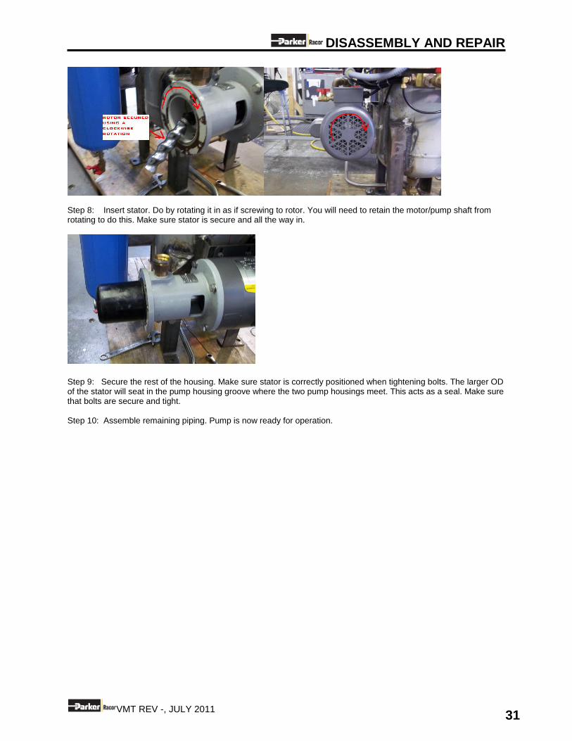
Step 8: Insert stator. Do by rotating it in as if screwing to rotor. You will need to retain the motor/pump shaft from rotating to do this. Make sure stator is secure and all the way in.
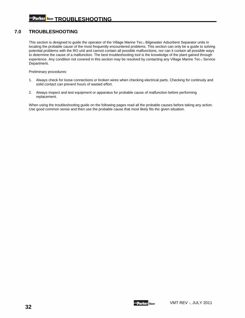
Step 9: Secure the rest of the housing. Make sure stator is correctly positioned when tightening bolts. The larger OD of the stator will seat in the pump housing groove where the two pump housings meet. This acts as a seal. Make sure that bolts are secure and tight. Step 10: Assemble remaining piping. Pump is now ready for operation.
TROUBLESHOOTING
32 VMT REV -, JULY 2011
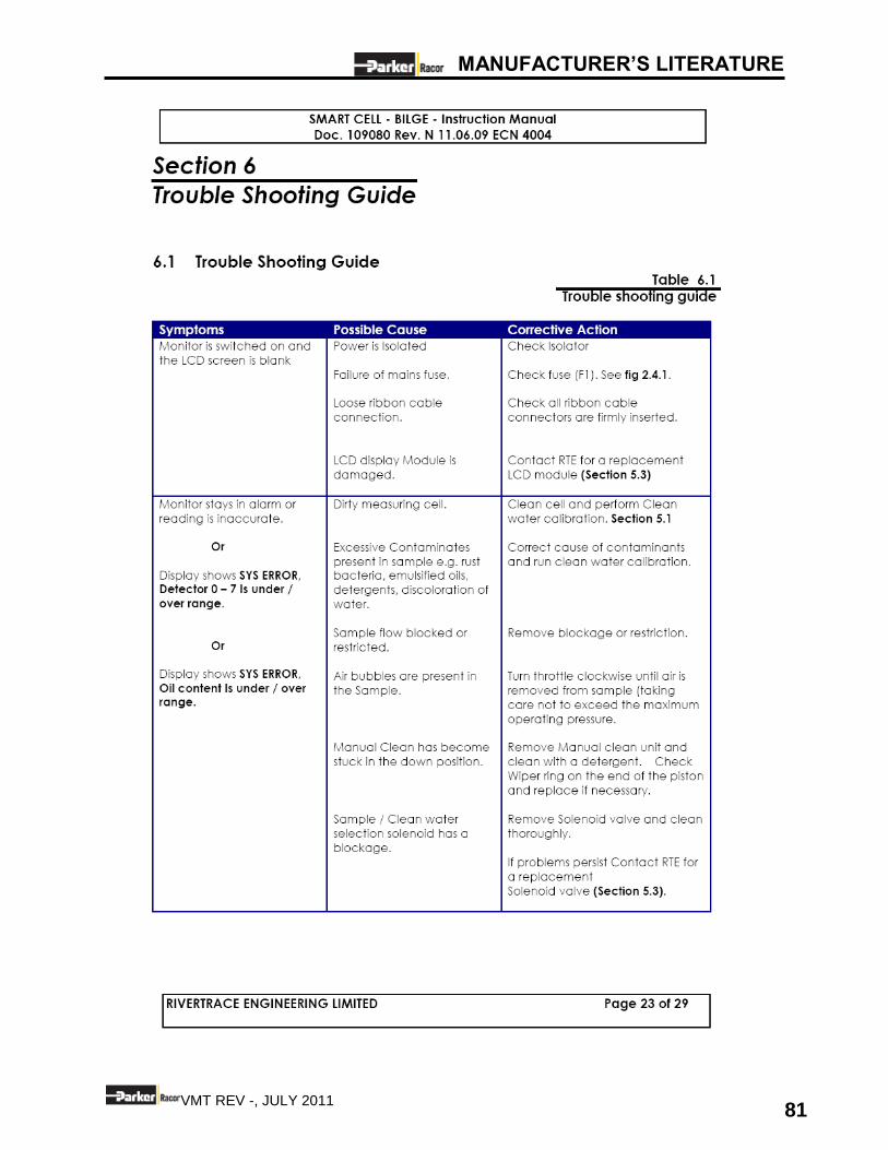
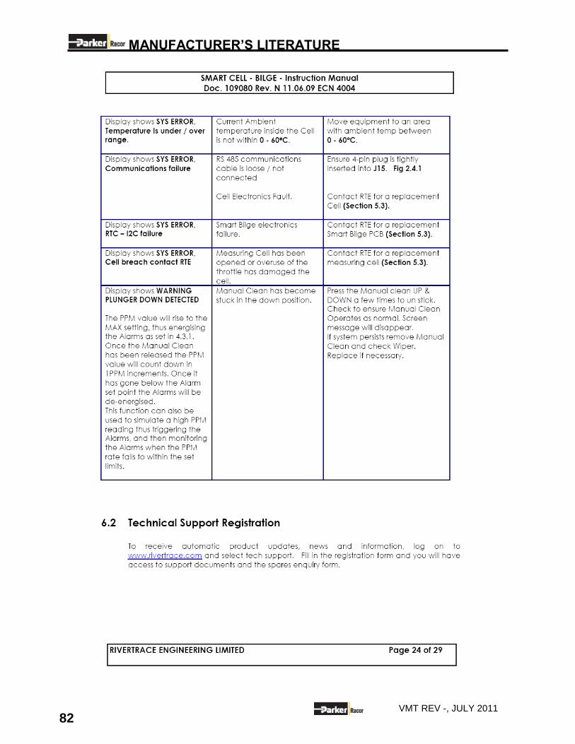
7.0 TROUBLESHOOTING This section is designed to guide the operator of the Village Marine Tec Bilgewater Adsorbent Separator units in locating the probable cause of the most frequently encountered problems. This section can only be a guide to solving potential problems with the RO unit and cannot contain all possible malfunctions, nor can it contain all possible ways to determine the cause of a malfunction. The best troubleshooting tool is the knowledge of the plant gained through
experience. Any condition not covered in this section may be resolved by contacting any Village Marine Tec Service Department. Preliminary procedures: 1. Always check for loose connections or broken wires when checking electrical parts. Checking for continuity and
solid contact can prevent hours of wasted effort. 2. Always inspect and test equipment or apparatus for probable cause of malfunction before performing
replacement. When using the troubleshooting guide on the following pages read all the probable causes before taking any action. Use good common sense and then use the probable cause that most likely fits the given situation.
TROUBLESHOOTING
33 VMT REV -, JULY 2011
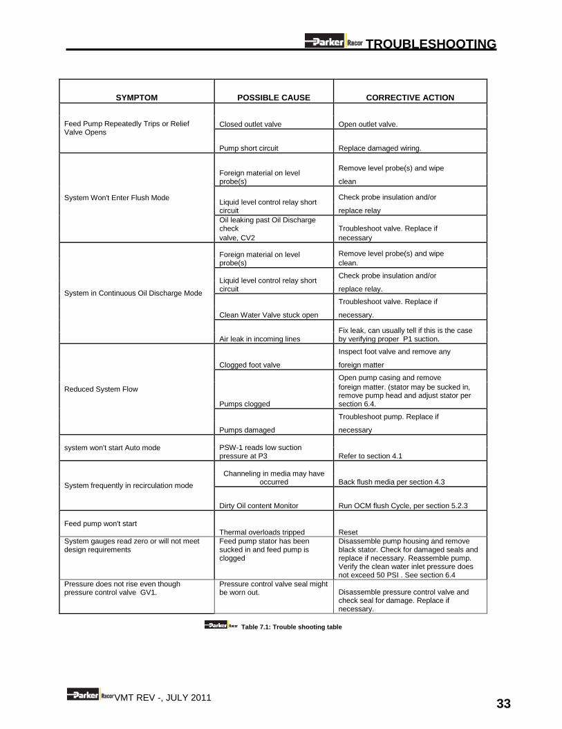
SYMPTOM POSSIBLE CAUSE CORRECTIVE ACTION
Feed Pump Repeatedly Trips or Relief Valve Opens
Closed outlet valve Open outlet valve.
Pump short circuit Replace damaged wiring.
System Won't Enter Flush Mode
Foreign material on level probe(s)
Remove level probe(s) and wipe
clean
Liquid level control relay short circuit
Check probe insulation and/or
replace relay
Oil leaking past Oil Discharge check Troubleshoot valve. Replace if
valve, CV2 necessary
System in Continuous Oil Discharge Mode
Foreign material on level probe(s)
Remove level probe(s) and wipe
clean.
Liquid level control relay short circuit
Check probe insulation and/or
replace relay.
Clean Water Valve stuck open
Troubleshoot valve. Replace if
necessary.
Air leak in incoming lines Fix leak, can usually tell if this is the case by verifying proper P1 suction.
Reduced System Flow
Clogged foot valve
Inspect foot valve and remove any
foreign matter
Pumps clogged
Open pump casing and remove
foreign matter. (stator may be sucked in, remove pump head and adjust stator per section 6.4.
Pumps damaged
Troubleshoot pump. Replace if
necessary
system won't start Auto mode PSW-1 reads low suction pressure at P3 Refer to section 4.1
System frequently in recirculation mode
Channeling in media may have occurred Back flush media per section 4.3
Dirty Oil content Monitor Run OCM flush Cycle, per section 5.2.3
Feed pump won't start Thermal overloads tripped Reset
System gauges read zero or will not meet design requirements
Feed pump stator has been sucked in and feed pump is clogged
Disassemble pump housing and remove black stator. Check for damaged seals and replace if necessary. Reassemble pump. Verify the clean water inlet pressure does not exceed 50 PSI . See section 6.4
Pressure does not rise even though pressure control valve GV1.
Pressure control valve seal might be worn out. Disassemble pressure control valve and
check seal for damage. Replace if necessary.
Table 7.1: Trouble shooting table
TROUBLESHOOTING
34 VMT REV -, JULY 2011
Reserved
DRAWINGS AND DIAGRAMS
35 VMT REV -, JULY 2011
8.0 DRAWINGS AND DIAGRAMS
DRAWINGS AND DIAGRAMS
36 VMT REV -, JULY 2011
DRAWINGS AND DIAGRAMS
37 VMT REV -, JULY 2011
DRAWINGS AND DIAGRAMS
38 VMT REV -, JULY 2011
DRAWINGS AND DIAGRAMS
39 VMT REV -, JULY 2011
DRAWINGS AND DIAGRAMS
40 VMT REV -, JULY 2011
PARTS REFERENCE
41 VMT REV -, JULY 2011
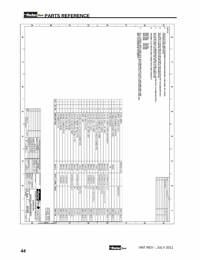
9.0 PARTS REFERENCE
9.1 SPARES AND CONSUMABLES
Description Part No.
Process filter 5 micron all models 33-0057
media fill kit (model BAS500) 90-5026
media fill kit (model BAS1000) 90-5028
media fill kit (model BAS2000 and BAS2500) 90-5029
Media (organic clay) all models 33-5012
Process filter and Membrane housing cover seal O-ring 33-0082
Switch, 3-pos 20-0029
Switch, 2-pos 20-0028
Light, Indicator, Green 20-3004
Light, Indicator, Red 20-3006
Light, Incandescent (110 VAC) 20-0505
Relay level control 110 VAC/50-60 20-0296
Feed pump seal kit (Models BAS2000-2500) 70-0392
Solenoid valve, ¾” FNPT 60-0121
Din connector, 20-5038
9.2 SPARES-OIL CONTENT MONITOR (SMART CELL-BILGE)
NOTE: At yearly intervals (or when necessary) the wiper ring on the manual clean assembly should be replaced.
This can be ordered from VMT directly as part no. 70-5031.
When ordering spares, it is important to supply details of the type of monitor, serial number of monitor, part number of each
spare required, its description and any other relevant information.
Description Part No.
Cell wiper ring 70-5031
Fuse 1.25A 70-5032
Smart Cell 70-5033
Smart Bilge PCB Assy (115) 70-5035
Membrane overlay 70-5036
LCD display module 70-5038
Smart Bilge Download Cable 70-5039
Solenoid Valve (115V) 70-5040
PARTS REFERENCE
42 VMT REV -, JULY 2011
PARTS REFERENCE
43 VMT REV -, JULY 2011
PARTS REFERENCE
44 VMT REV -, JULY 2011
PARTS REFERENCE
45 VMT REV -, JULY 2011
PARTS REFERENCE
46 VMT REV -, JULY 2011
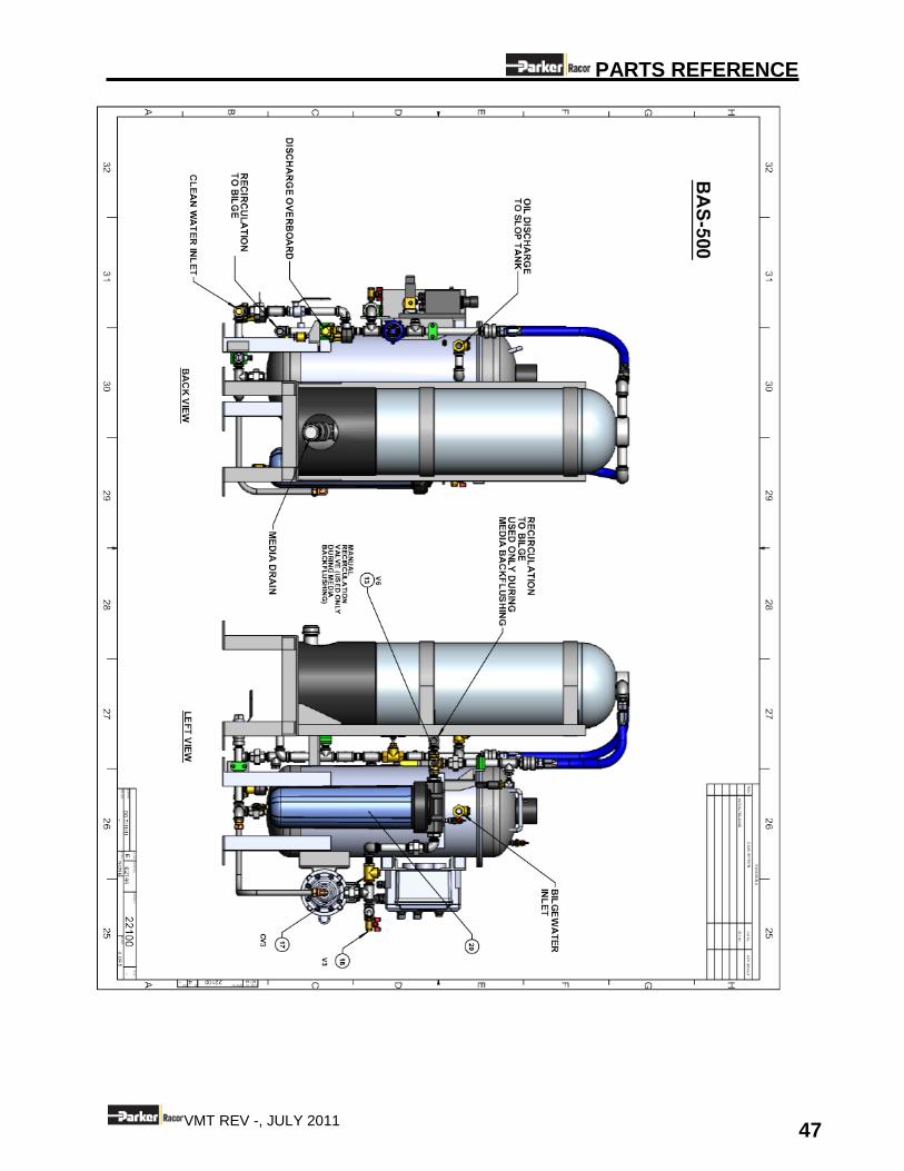
PARTS REFERENCE
47 VMT REV -, JULY 2011
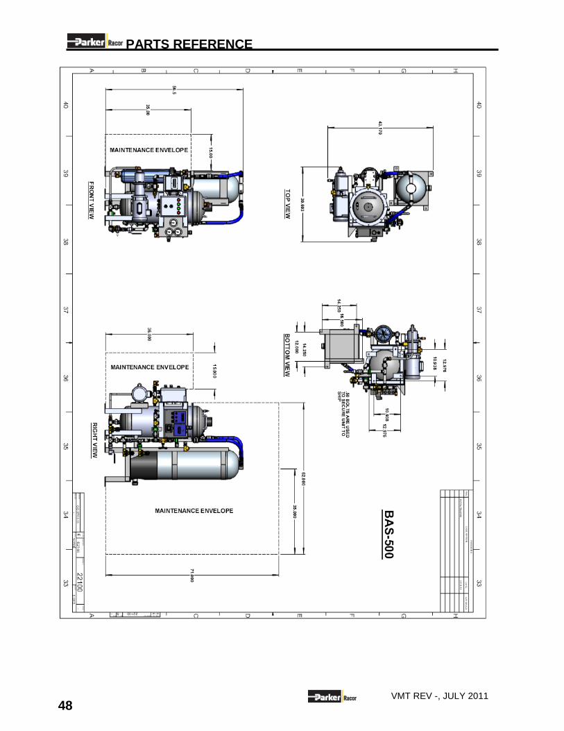
PARTS REFERENCE
48 VMT REV -, JULY 2011
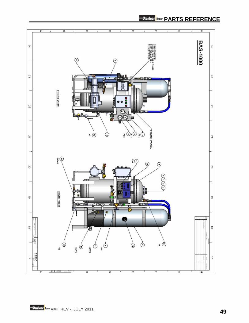
PARTS REFERENCE
49 VMT REV -, JULY 2011
PARTS REFERENCE
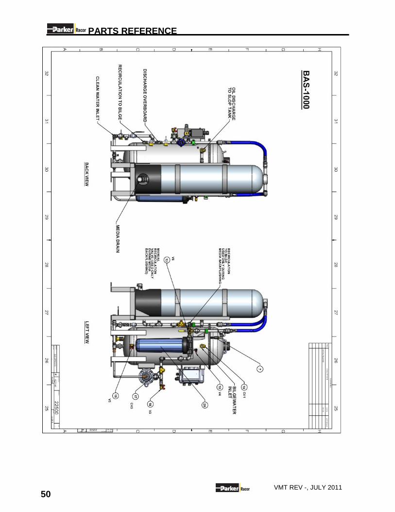
50 VMT REV -, JULY 2011
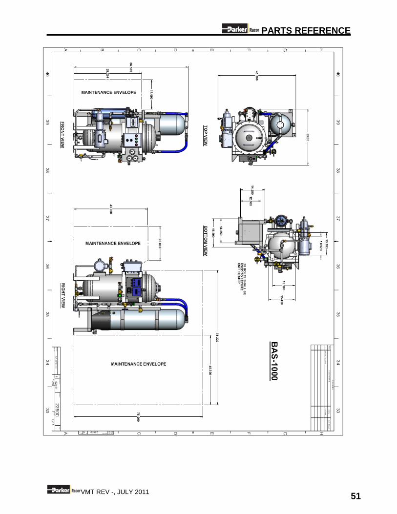
PARTS REFERENCE
51 VMT REV -, JULY 2011
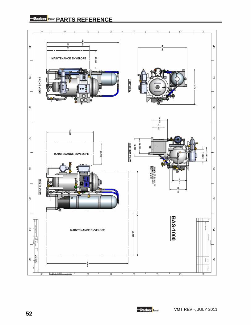
PARTS REFERENCE
52 VMT REV -, JULY 2011
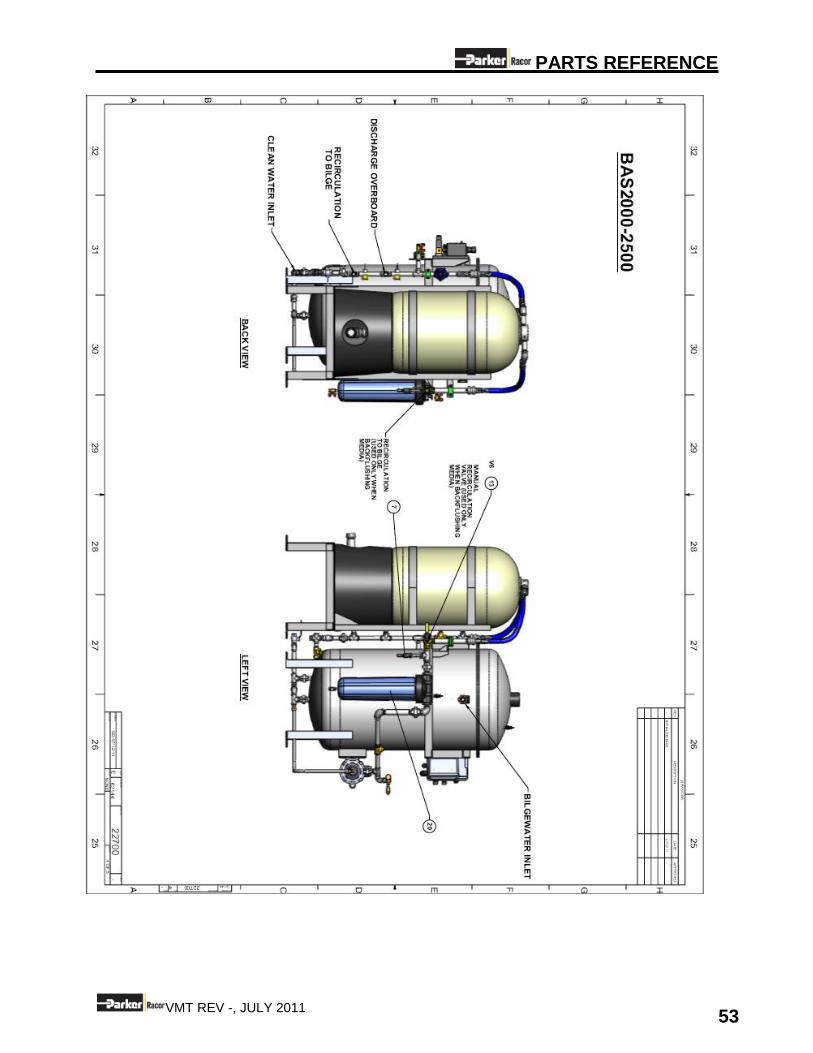
PARTS REFERENCE
53 VMT REV -, JULY 2011
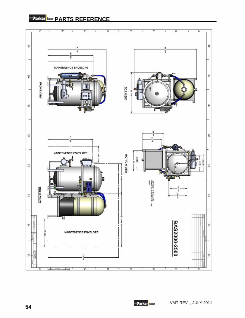
PARTS REFERENCE
54 VMT REV -, JULY 2011
PARTS REFERENCE
55 VMT REV -, JULY 2011
PARTS REFERENCE
56 VMT REV -, JULY 2011
MANUFACTURER’S LITERATURE
57 VMT REV -, JULY 2011
10.0 MANUFACTURER’S LITERATURE
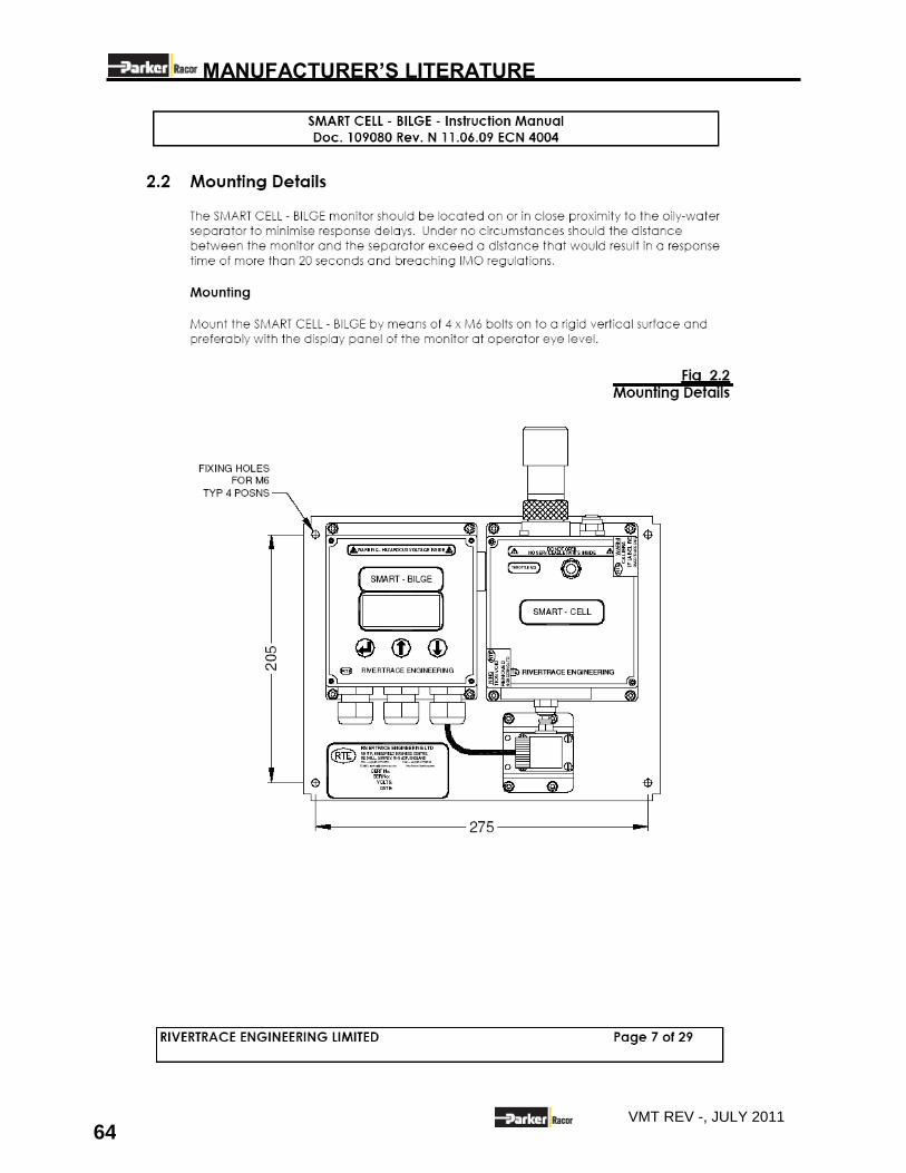
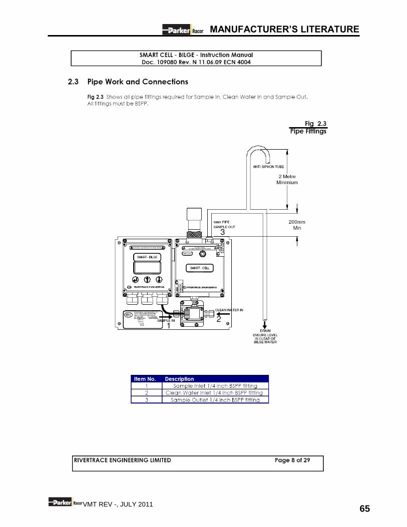
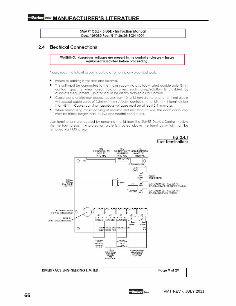
10.1 SMART CELL- BILGE- INSTRUCTION MANUAL
10.2 PROGRESSIVE CAVITY PUMP SPARE PARTS
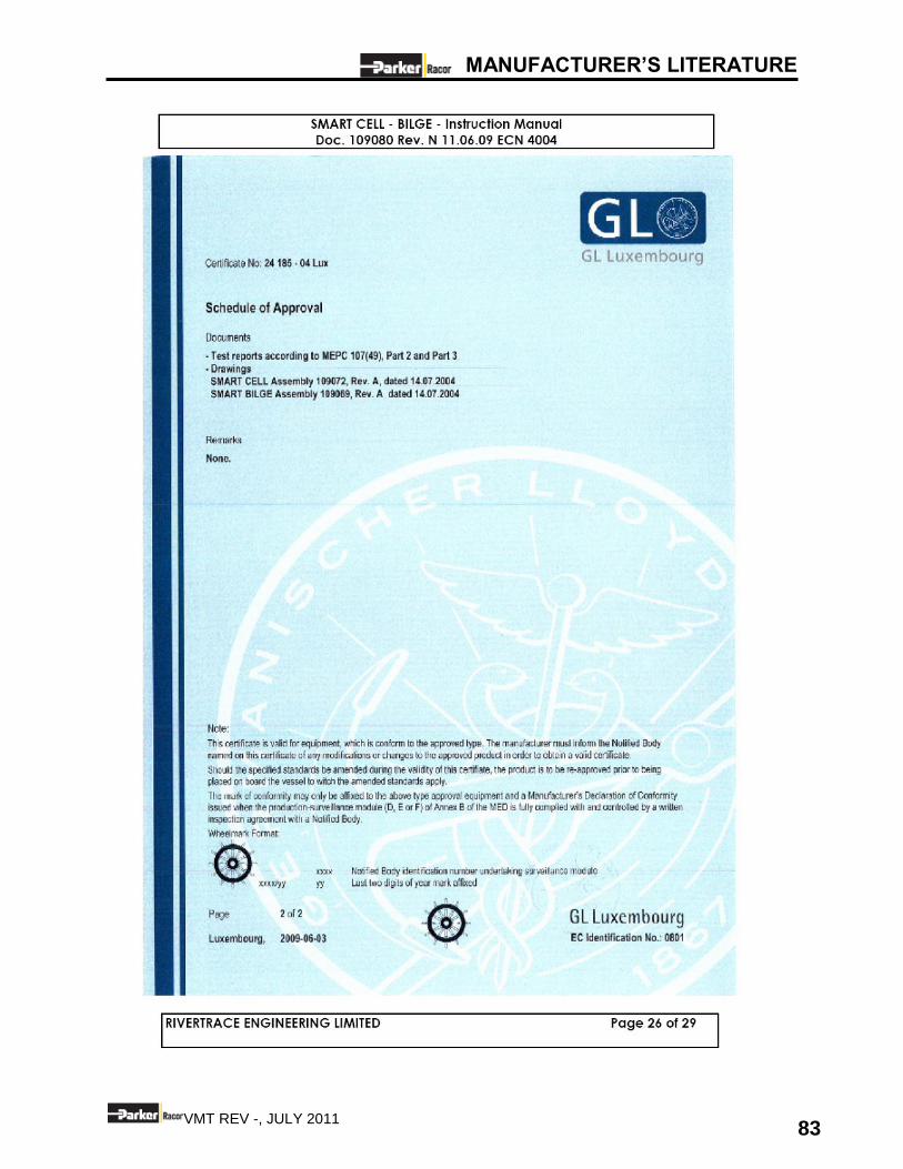
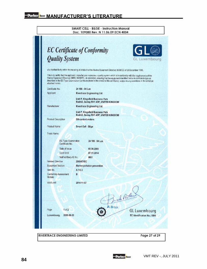
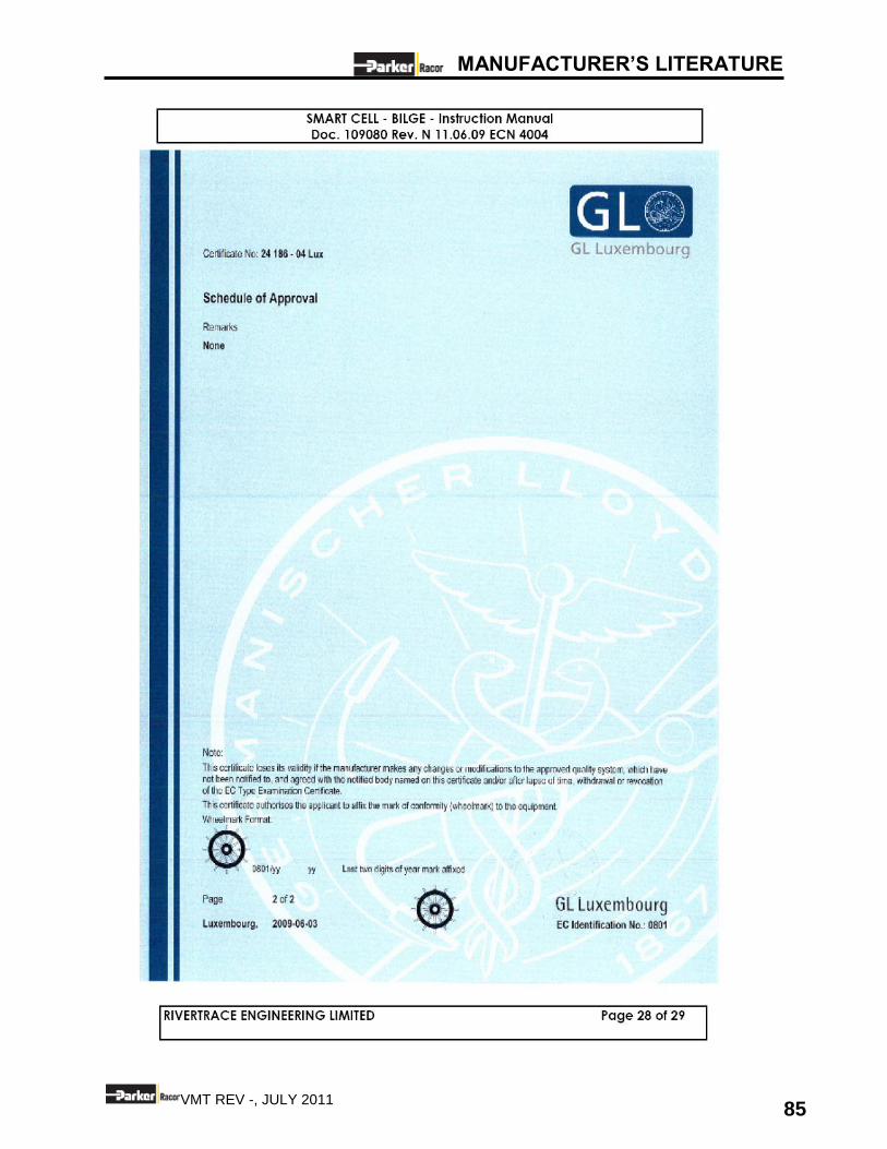
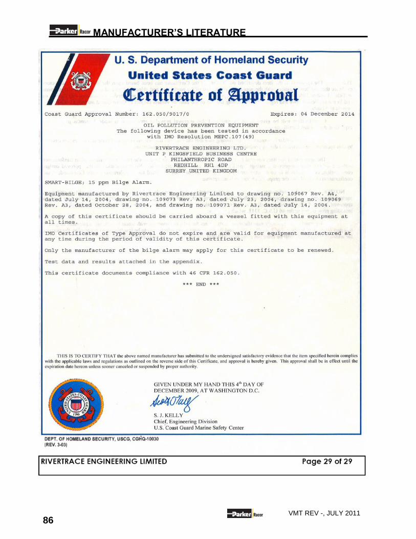
10.3 CERTIFICATES

MANUFACTURER’S LITERATURE
58 VMT REV -, JULY 2011
MANUFACTURER’S LITERATURE
59 VMT REV -, JULY 2011
MANUFACTURER’S LITERATURE
60 VMT REV -, JULY 2011
MANUFACTURER’S LITERATURE
61 VMT REV -, JULY 2011
MANUFACTURER’S LITERATURE
62 VMT REV -, JULY 2011
MANUFACTURER’S LITERATURE
63 VMT REV -, JULY 2011
MANUFACTURER’S LITERATURE
64 VMT REV -, JULY 2011
MANUFACTURER’S LITERATURE
65 VMT REV -, JULY 2011
MANUFACTURER’S LITERATURE
66 VMT REV -, JULY 2011
MANUFACTURER’S LITERATURE
67 VMT REV -, JULY 2011
MANUFACTURER’S LITERATURE
68 VMT REV -, JULY 2011
MANUFACTURER’S LITERATURE
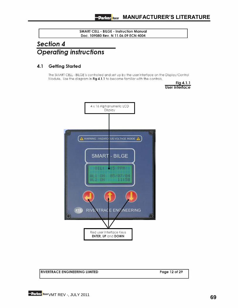
69 VMT REV -, JULY 2011
MANUFACTURER’S LITERATURE
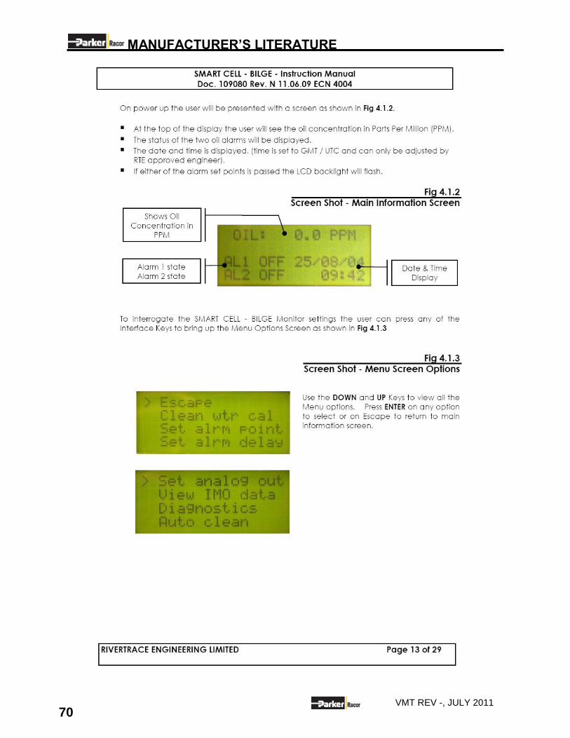
70 VMT REV -, JULY 2011
MANUFACTURER’S LITERATURE
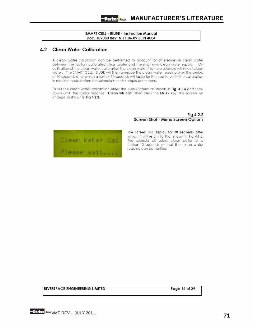
71 VMT REV -, JULY 2011
MANUFACTURER’S LITERATURE
72 VMT REV -, JULY 2011
MANUFACTURER’S LITERATURE
73 VMT REV -, JULY 2011
MANUFACTURER’S LITERATURE
74 VMT REV -, JULY 2011
MANUFACTURER’S LITERATURE
75 VMT REV -, JULY 2011
MANUFACTURER’S LITERATURE
76 VMT REV -, JULY 2011

MANUFACTURER’S LITERATURE
77 VMT REV -, JULY 2011
MANUFACTURER’S LITERATURE
78 VMT REV -, JULY 2011
MANUFACTURER’S LITERATURE
79 VMT REV -, JULY 2011
MANUFACTURER’S LITERATURE
80 VMT REV -, JULY 2011
MANUFACTURER’S LITERATURE
81 VMT REV -, JULY 2011
MANUFACTURER’S LITERATURE
82 VMT REV -, JULY 2011
MANUFACTURER’S LITERATURE
83 VMT REV -, JULY 2011
MANUFACTURER’S LITERATURE
84 VMT REV -, JULY 2011
MANUFACTURER’S LITERATURE
85 VMT REV -, JULY 2011
MANUFACTURER’S LITERATURE
86 VMT REV -, JULY 2011
Recommended