Biaxial Stress System
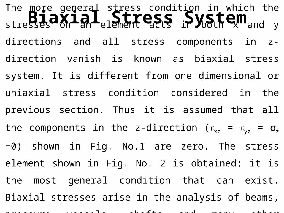
The more general stress condition in which the stresses on an element
acts in both x and y directions and all stress components in z- direction
vanish is known as biaxial stress system. It is different from one
dimensional or uniaxial stress condition considered in the previous
section. Thus it is assumed that all the components in the z-direction
(xz = yz = σz =0) shown in Fig. No.1 are zero. The stress element
shown in Fig. No. 2 is obtained; it is the most general condition that can
exist. Biaxial stresses arise in the analysis of beams, pressure vessels,
shafts and many other structural members.
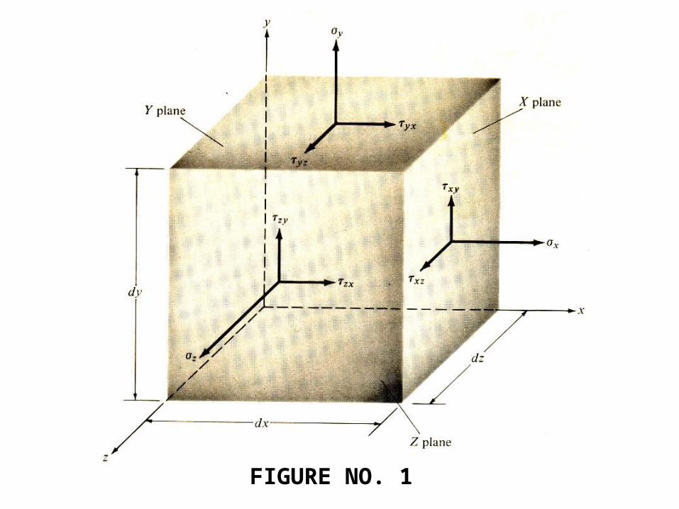
FIGURE NO. 1
xy
σy
xy
xy
xy
σy
σx σx
y
x
FIGURE NO. 2
A class of common engineering problems involving stresses in a thin
plate or free surface of a structural element, such as the surfaces of thin
walled pressure vessels under external or internal pressure, the free
surface of shafts in torsion or beams under transverse loads.
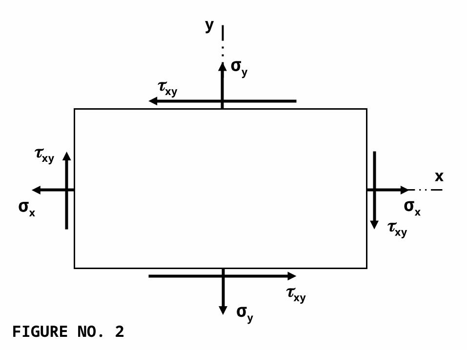
General case of two dimensional stress.
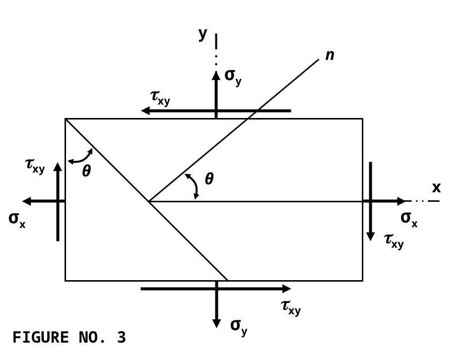
In general if a plane element is removed from a body it will be
subjected to the normal stresses σx and σy together with the shearing
stress xy as shown in fig 3. It is desirable to investigate the state of
stress on any inclined plane t defined by angle θ, positive ccw as shown
in fig 4. The resulting relations would make it possible to determine
θxy
σy
xy
xy
xy
σy
σx σx
y
xθ
n
FIGURE NO. 3
normal stress σn and the shear stress on the inclined plane t form
normal n to the inclined plane t form knowledge of normal and shear
stresses on the X and Y planes (usually known). Note that the normal n
to the inclined plane t make an angle θ with the x-axis. This angle θ is
considered to be positive when measured in the ccw direction from the
positive end of the x-axis. According to sign convention, which is the
one used throughout this text, a shear stress is positive if it produces
clockwise rotation of the element on which it is acting and negative if it
produces counterclockwise rotation. Thus xy on the X plane in Figure
is positive while xy on the Y plane
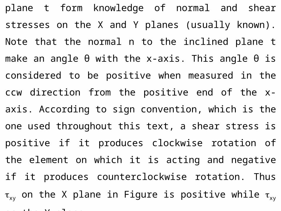
(i.e., yx) is negative. However, as was stated earlier, normal stresses are
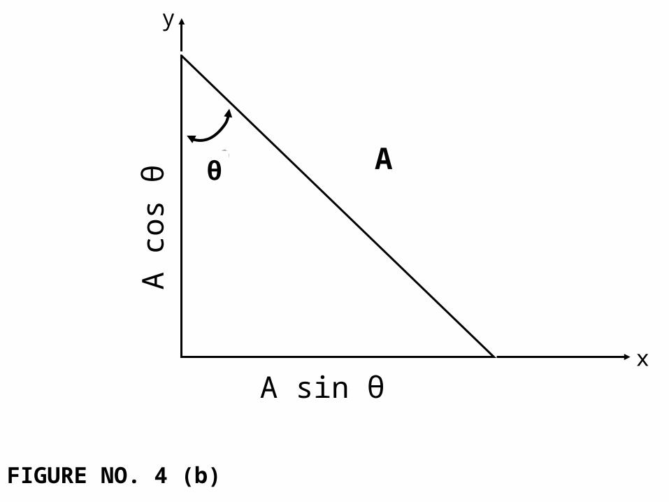
positive if tensile and negative if compressive. Isolate the small wedge
to the left of the inclined plane and construct its free-body diagram as
shown in Figure (4). If one assumes the area of the inclined plane to be
A square units, then the area of the X plane would be A cos θ square
units and the area of the Y plane would be A sin θ square units, as
shown in Figure (5). Thus the forces on the three faces of the wedge
produced by the normal and shear stresses acting on them can be
determined in terms of A and the trigonometric functions of the angle θ,
as shown in Figure (5).
θ σnxy
σx
σy
xy
n
t
x
y
θ
FIGURE NO. 4 (a)
θ
θ A
A sin θx
y
FIGURE NO. 4 (b)
A c
os θ
θ
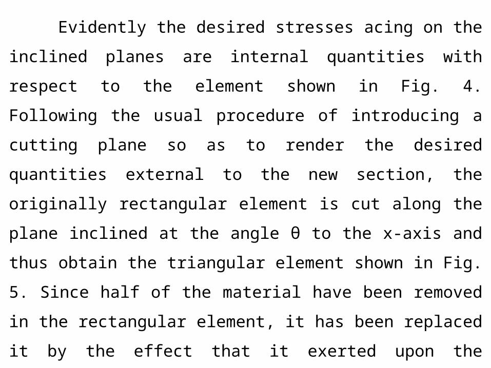
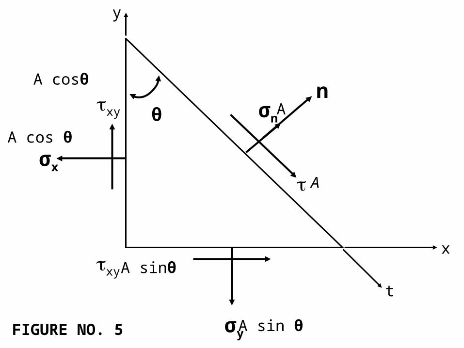
Evidently the desired stresses acing on the inclined planes are
internal quantities with respect to the element shown in Fig. 4.
Following the usual procedure of introducing a cutting plane so as to
render the desired quantities external to the new section, the originally
rectangular element is cut along the plane inclined at the angle θ to the
x-axis and thus obtain the triangular element shown in Fig. 5. Since half
of the material have been removed in the rectangular element, it has
been replaced it by the effect that it exerted upon the remaining lower
triangle shown and this effect in general consists of both normal and
shearing forces acting along the inclined plane.
θ σnxy
σx
σy
xy
n
t
x
y
θ
FIGURE NO. 5
A
A
A cos θ
A cosθ
A sinθ
A sin θ
θ
σn. A
.A
xy .A cosθ
σx .A cosθ
σy .A sinθ
yx .A sinθ
y
x
θθ
τ yx .A
sinθ.c
osθθ
τyx .A sinθ.sinθ
θ
σy .A sinθ.sinθ
σy .A sinθ.cosθ
θ xy
.A. co
sθ.sinθ
xy .A. cosθ.cosθ
θ
σ x .A
. cosθ.c
osθ
σx .A. cosθ.sinθ
FIGURE NO. 6
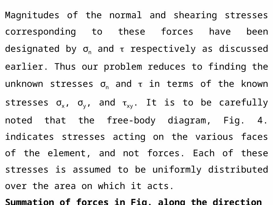
Magnitudes of the normal and shearing stresses corresponding to these
forces have been designated by σn and respectively as discussed
earlier. Thus our problem reduces to finding the unknown stresses σn
and in terms of the known stresses σx, σy, and xy. It is to be carefully
noted that the free-body diagram, Fig. 4. indicates stresses acting on the
various faces of the element, and not forces. Each of these stresses is
assumed to be uniformly distributed over the area on which it acts.
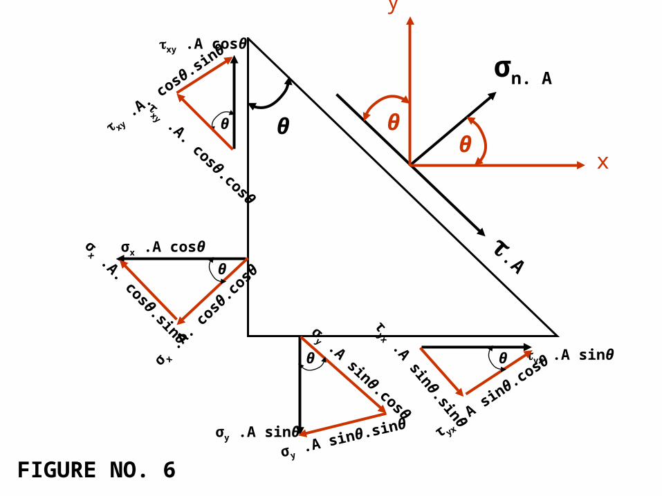
Summation of forces in Fig. along the direction of σn ΣFn = 0.
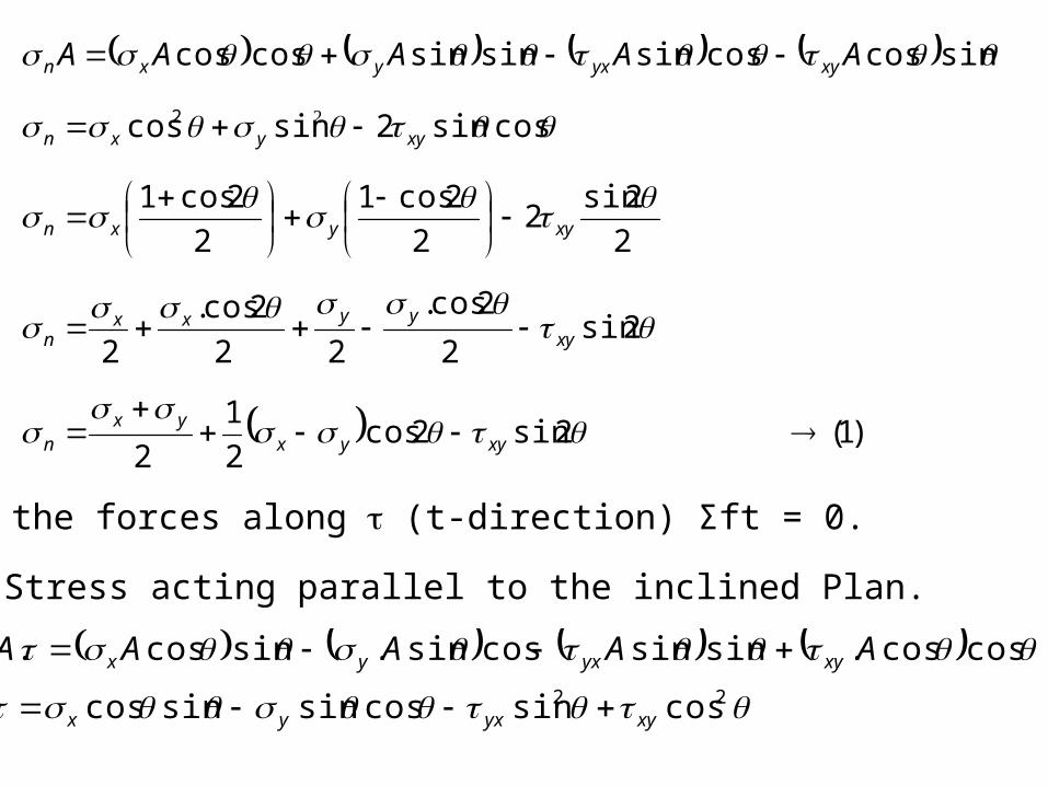
Shearing Stress acting parallel to the inclined Plan.
Summing the forces along (t-direction) Σft = 0.
)1(2sin2cos2
1
2
2sin2
2cos.
22
2cos.
2
2
2sin2
2
2cos1
2
2cos1
cossin2sincos
sincoscossinsinsincoscos
2
xyyxyx
n
xyyyxx
n
xyyxn
xyyxn
xyyxyxn AAAAA
22 cossincossinsincos
coscos.sinsincossin.sincos.
xyyxyx
xyyxyx AAAAA
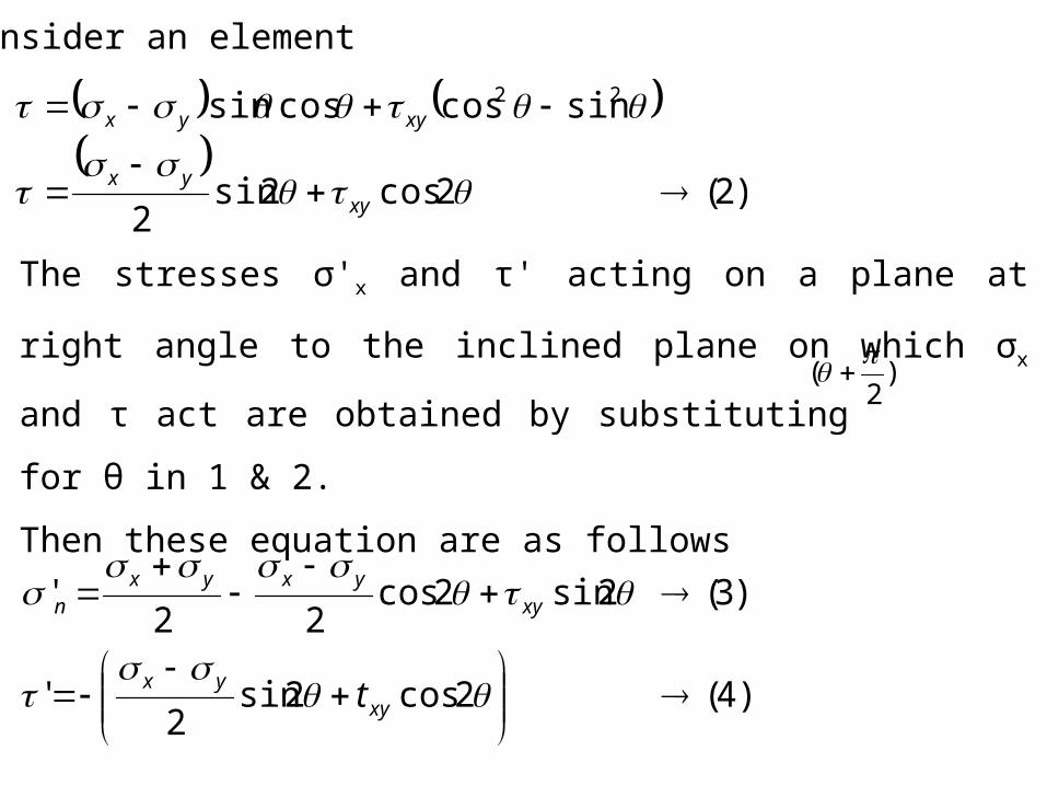
Consider an element
)2(2cos2sin2
sincoscossin 22
xyyx
xyyx
The stresses σ'x and τ' acting on a plane at right angle to the inclined
plane on which σx and τ act are obtained by substituting for θ in
1 & 2.
Then these equation are as follows
)2
(
)4(2cos2sin2
'
)3(2sin2cos22
'
xyyx
xyyxyx
n
t
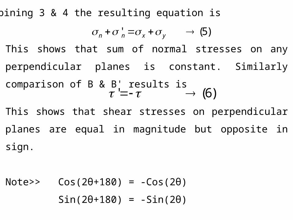
By combining 3 & 4 the resulting equation is
)5(' yxnn
This shows that sum of normal stresses on any perpendicular planes is
constant. Similarly comparison of B & B' results is
)6('
This shows that shear stresses on perpendicular planes are equal in
magnitude but opposite in sign.
Note>> Cos(2θ+180) = -Cos(2θ)
Sin(2θ+180) = -Sin(2θ)
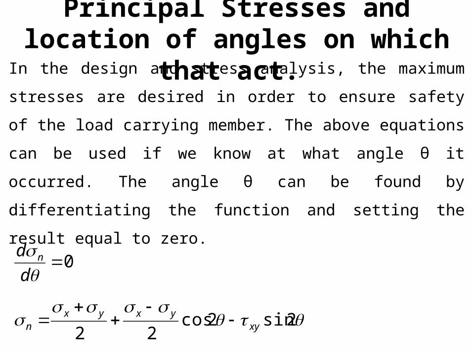
Principal Stresses and location of angles on which that act.
In the design and stress analysis, the maximum stresses are desired in
order to ensure safety of the load carrying member. The above
equations can be used if we know at what angle θ it occurred. The angle
θ can be found by differentiating the function and setting the result
equal to zero.
2sin2cos22
0
xyyxyx
n
n
d
d
)8(2
tan2
1
)7(2
2tan
22tan0
2cos
2cos2
2cos
2sin0
2cos22sin0
)2(2cos)2(2sin2
0
1
yx
xyP
yx
xyP
xyyx
xyyx
xyyx
xyyxn
d
d
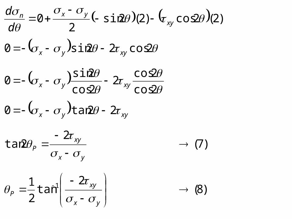
Equations 7 & 8 define the planes of maximum and minimum normal
stresses.
Planes defined by equation 7 and 8 are known as principal planes. Thus
there are two solutions of equation 7, and two values of 2θp (differing
by 180o) and also two values of θp (differing by 90o).
The normal stresses that exist on these planes are called principal
stresses. On one of these two planes, the normal stress is maximum and
on the second the normal stress is minimum. It will be further shown
that the Principal Plane are free from shear stresses and therefore
another way of defining is that the Principal stress are the normal
stresses acting on the planes on which shear stresses are zero.
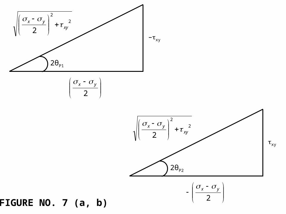
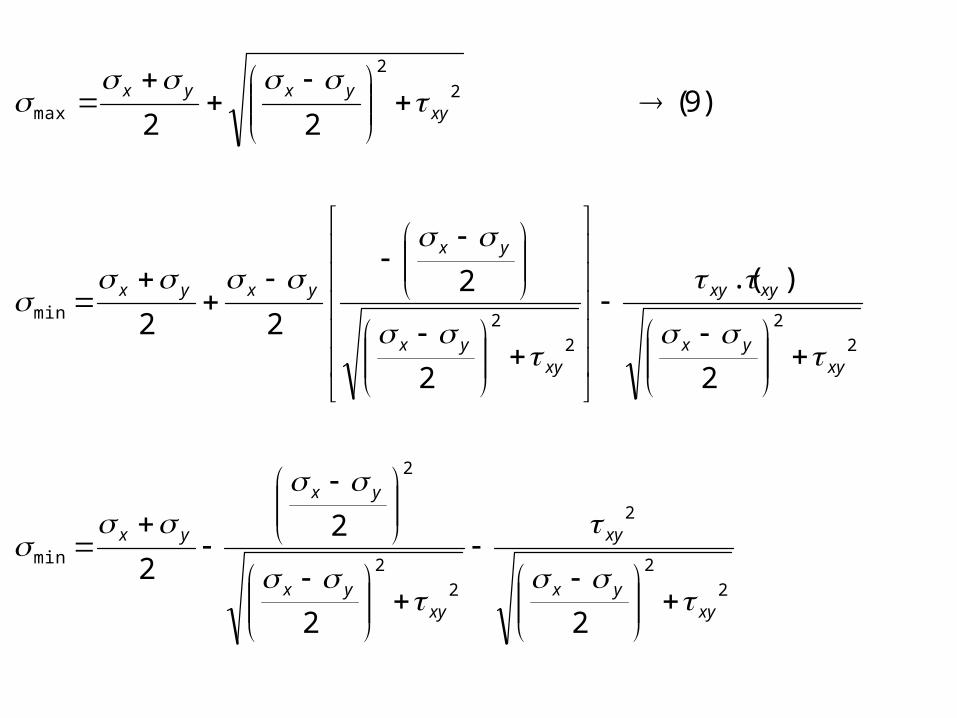
Values of maximum and minimum normal stresses can be obtained by
substituting values of θP from 7 or 8 into 1. In order to get cos2θ and
sin 2θ a right angle triangle is drawn as shown in Fig 7 (a & b).
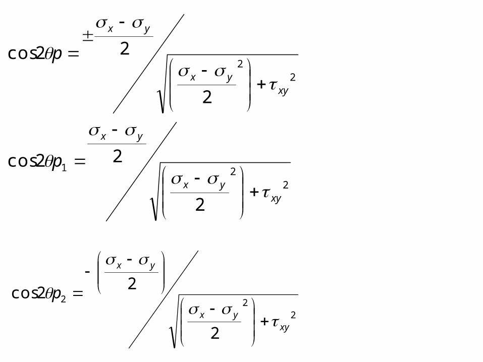
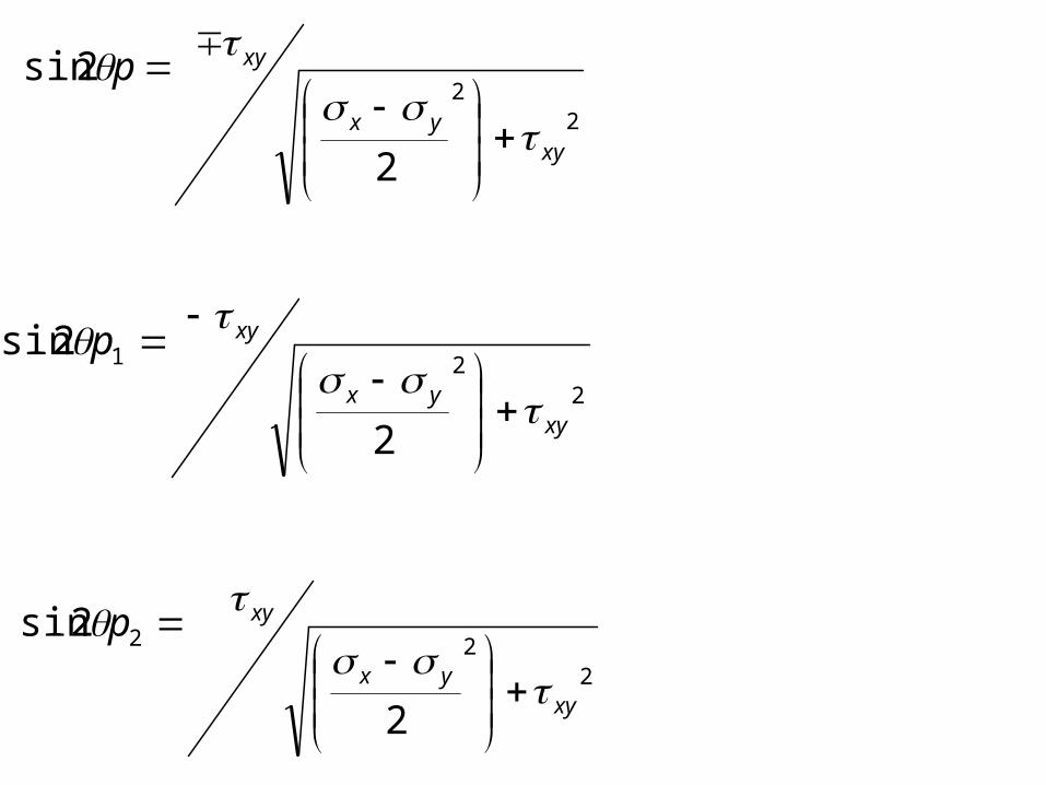
The values of sin 2θp and cos 2θp as found from the above two diagram
may now be substituted in equation (1) to get maximum and minimum
values of normal stresses.
2θP1
2
2
2 xyyx
–xy
2yx
FIGURE NO. 7 (a, b)
2θP2
2
2
2 xyyx
xy
2yx
221
22
2
22cos
2
22cos
xyyx
yx
xyyx
yx
p
p
222
2
22cos
xyyx
yx
p
22
2
2sin
xyyx
xyp
221
2
2sin
xyyx
xyp
222
2
2sin
xyyx
xyp
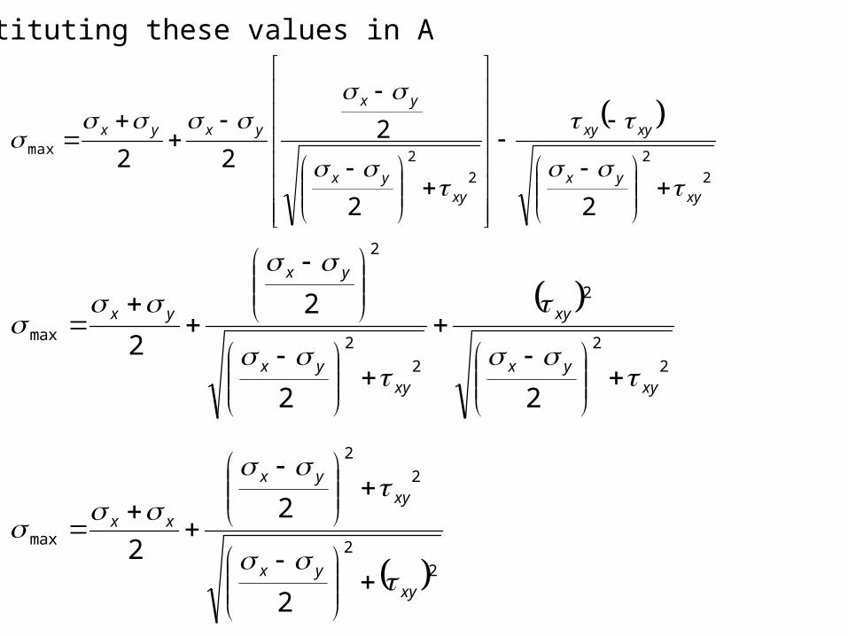
Substituting these values in A
2
2
2
2max
22
222
xyyx
xyxy
xyyx
yx
yxyx
2
2
2
2
max
2
2
2
2
2
2
max
2
2
2
22
2
2
xyyx
xyyx
xx
xyyx
xy
xyyx
yx
yx
2
2
2
2
2
2
min
2
2
2
2min
2
2
max
22
2
2
2
).(
2
2
22
)9(22
xyyx
xy
xyyx
yx
yx
xyyx
xyxy
xyyx
yx
yxyx
xyyxyx
)10(22
2
2
2
2
2
min
2
2
2
2
min
xyyxyx
xyyx
xyyx
yx
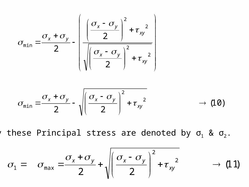
Normally these Principal stress are denoted by σ1 & σ2.
)11(22
2
2
max1
xy
yxyx
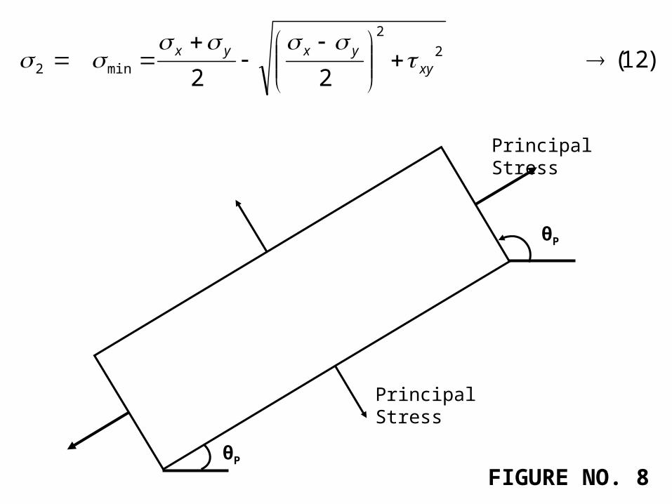
)12(22
2
2
min2
xy
yxyx
θP
θP
Principal Stress
Principal Stress
FIGURE NO. 8
The stresses given by 11 and 12 are the principal stresses and they
occur the on the principal plane. By substituting one of the values of θp
from equation 7 into equation 1 one may readily determine which of the
two principal stresses is acting on that plane. The other Principal stress
naturally acts on the other Principal plane.
Another useful relation is obtained by adding the values of Principal
stresses
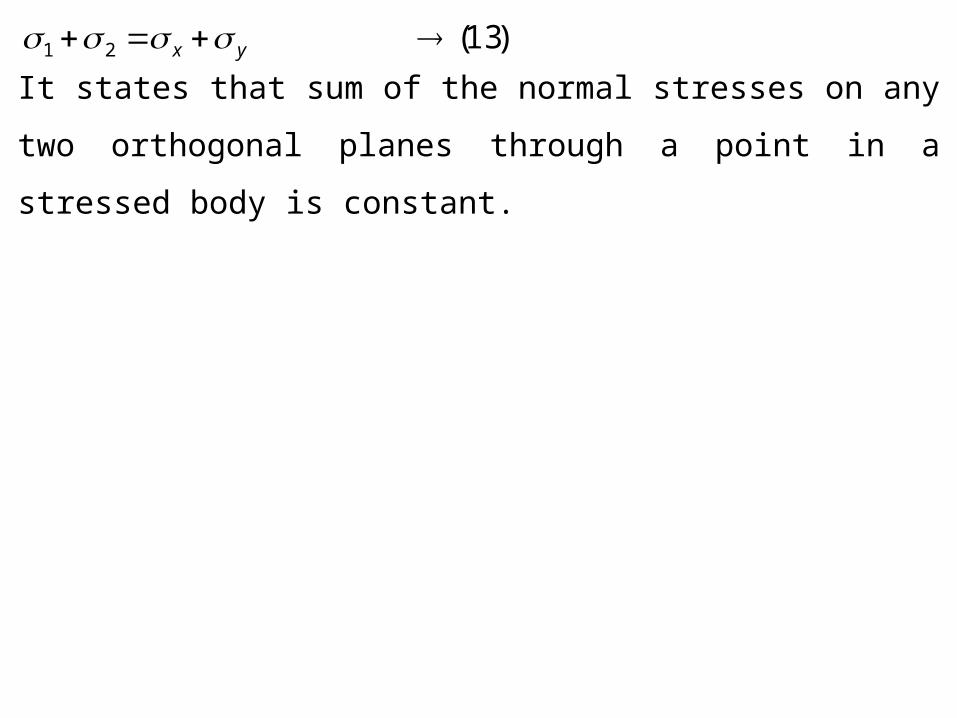
)13(21 yx
It states that sum of the normal stresses on any two orthogonal planes
through a point in a stressed body is constant.
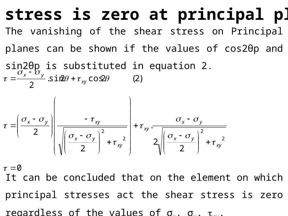
It can be concluded that on the element on which principal stresses act
the shear stress is zero regardless of the values of σx, σy, xy.
Shear stress is zero at principal plane.
The vanishing of the shear stress on Principal planes can be shown if
the values of cos2θp and sin2θp is substituted in equation 2.
0
22
.
2
2
)2(2cos2sin.2
2
2
2
2
xyyx
yxxy
xyyx
xyyx
xyyx
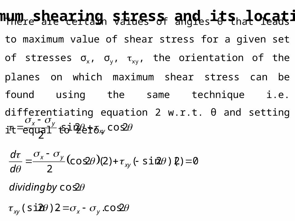
Maximum shearing stress and its location.
There are certain values of angles θ that leads to maximum value of
shear stress for a given set of stresses σx, σy, xy, the orientation of the
planes on which maximum shear stress can be found using the same
technique i.e. differentiating equation 2 w.r.t. θ and setting it equal to
zero.
2cos.2).2(sin
2cos
0)2)(2sin()2(2cos2
2cos2sin.2
yxxy
xyyx
xyyx
bydividing
d
d
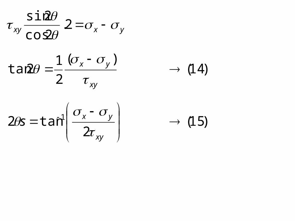
)15(2
tan2
)14()(
2
12tan
2.2cos
2sin
1
xy
yx
xy
yx
yxxy
s
Maximum shearing stress
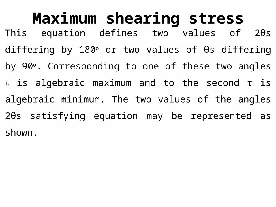
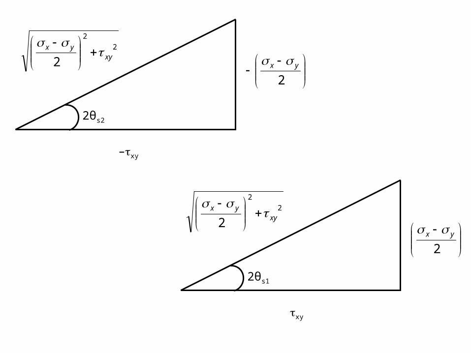
This equation defines two values of 2θs differing by 180o or two values
of θs differing by 90o. Corresponding to one of these two angles is
algebraic maximum and to the second τ is algebraic minimum. The two
values of the angles 2θs satisfying equation may be represented as
shown.
2θs2
2
2
2 xyyx
–xy
2yx
2θs1
2
2
2 xyyx
xy
2
yx
Rs
Rs
Rs
Rs
Rs
xy
xy
xy
yx
yx
2
1
2
1
2cos
2cos
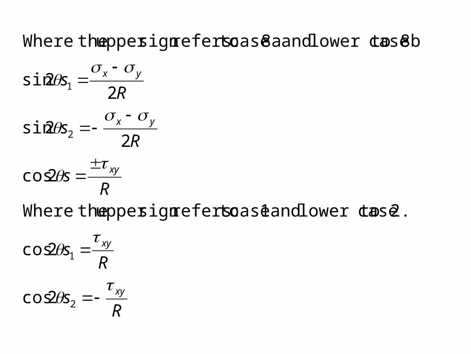
2. case lower to and 1 case toreferssign upper theWhere
2cos
22sin
22sin
8b. case lower to and 8a case toreferssign upper theWhere
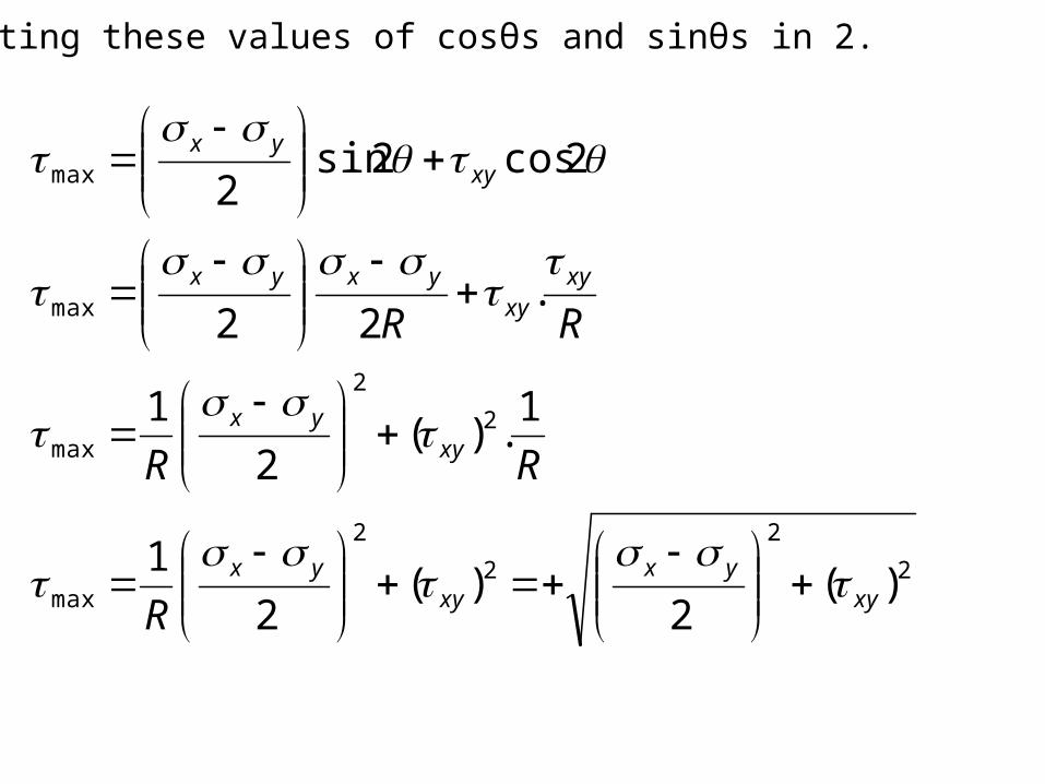
Substituting these values of cosθs and sinθs in 2.
2
2
2
2
max
2
2
max
max
max
)(2
)(2
1
1.)(
2
1
.22
2cos2sin2
xyyx
xyyx
xyyx
xyxy
yxyx
xyyx
R
RR
RR
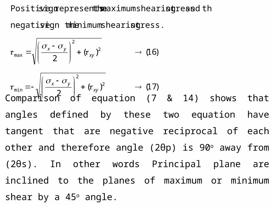
)17()(2
)16()(2
stress. shearing minimum sign the negative
theand stress shearing maximum therepresentssign Positive
2
2
min
2
2
max
xyyx
xyyx
Comparison of equation (7 & 14) shows that angles defined by these
two equation have tangent that are negative reciprocal of each other and
therefore angle (2θp) is 90o away from (2θs). In other words Principal
plane are inclined to the planes of maximum or minimum shear by a
45o angle.
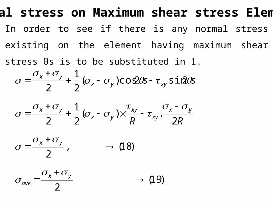
Normal stress on Maximum shear stress Element
In order to see if there is any normal stress existing on the element
having maximum shear stress θs is to be substituted in 1.
)19(2
)18(,2
2.)(
2
1
2
2sin2cos)(2
1
2
yxave
yx
yxxy
xyyx
yx
xyyxyx
RR
ss
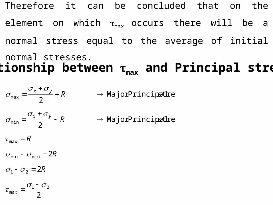
Therefore it can be concluded that on the element on which max occurs
there will be a normal stress equal to the average of initial normal
stresses.
Relationship between max and Principal stress.
2
2
2
stressPrincipalMajor2
stressPrincipalMajor2
21max
21
minmax
max
min
max
R
R
R
R
R
yx
yx
Major or Minor Principal stresses.
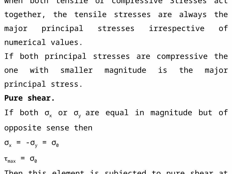
when both tensile or compressive Stresses act together, the tensile
stresses are always the major principal stresses irrespective of
numerical values.
If both principal stresses are compressive the one with smaller
magnitude is the major principal stress.
Pure shear.
If both σx or σy are equal in magnitude but of opposite sense then
σx = -σy = σ0
max = σ0
Then this element is subjected to pure shear at an angle of 45°.
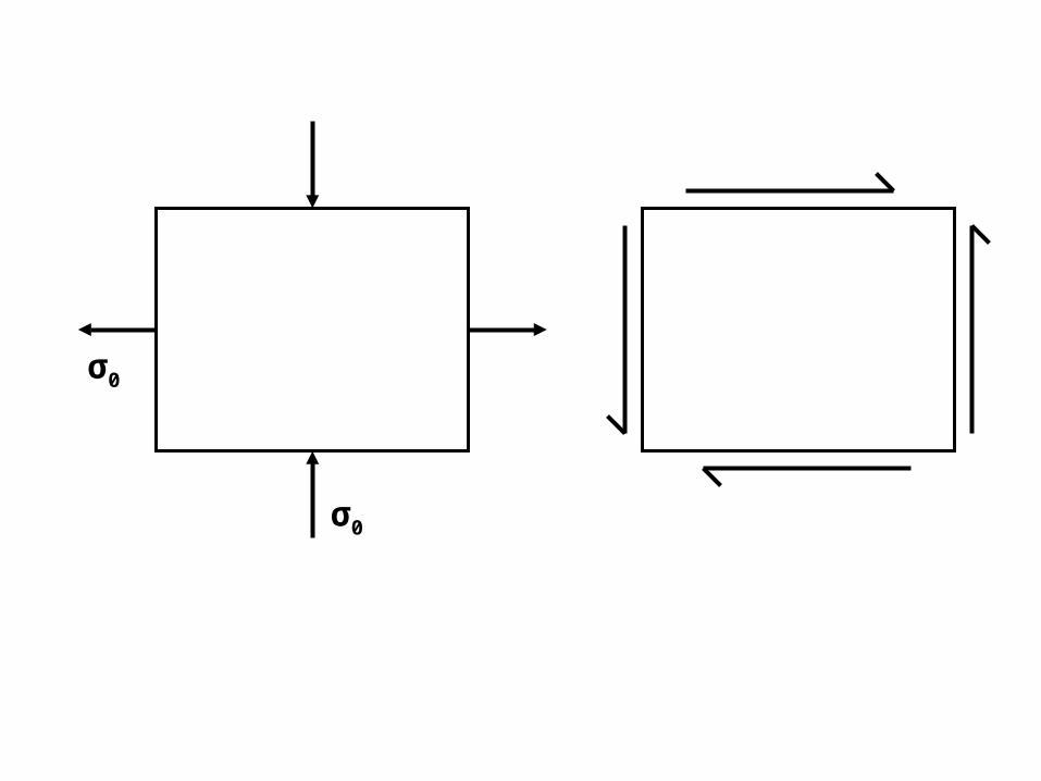
σ0
σ0
Recommended