1
Best Practice Network Design for the Data CenterMihai Dumitru, CCIE2 #16616
.
2
39 employees, 3 national offices
Focus on large enterprise customers from banking and retail, plus education
Specializing in:– System integration (consulting, project management, network equipment sale and deployment, maintenance)– Managed services (operational support, network management, server hosting and business continuity)
Cisco Gold Partner– One triple CCIE, one dual CCIE and more…
Solarwinds Gold Partner
A Few Words about Cronus eBusiness:
3
Classical Data Center Network Architecture
Impact of new features and products on hierarchical design for data center networks
Data center services insertion
Layer 3 features and best practices
Layer 2 features, enhancements and best practices
What We Will Cover In This Session:
4
Data Center Core
Enterprise Network
Aggregation
Access
Layer 3 Links
Layer 2 Trunks
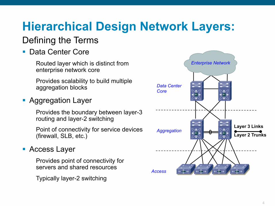
Hierarchical Design Network Layers:
Data Center CoreRouted layer which is distinct from enterprise network core
Provides scalability to build multiple aggregation blocks
Aggregation LayerProvides the boundary between layer-3 routing and layer-2 switching
Point of connectivity for service devices (firewall, SLB, etc.)
Access LayerProvides point of connectivity for servers and shared resources
Typically layer-2 switching
Defining the Terms
5
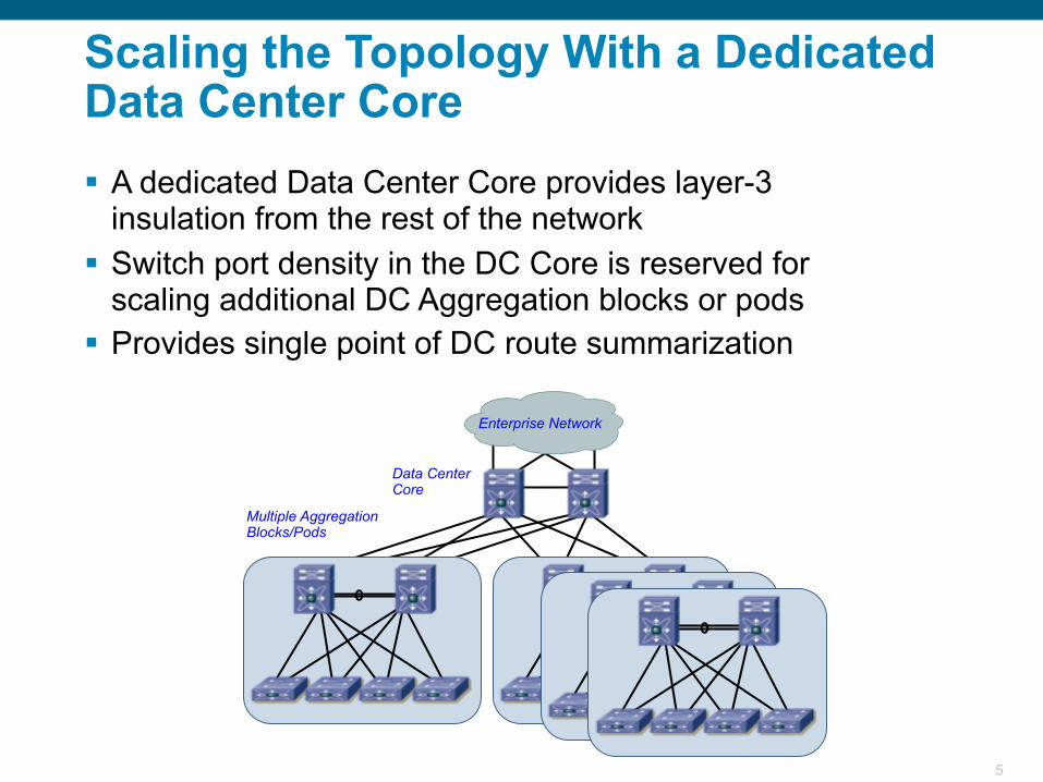
Data Center Core
Enterprise Network
Multiple Aggregation Blocks/Pods
Scaling the Topology With a Dedicated Data Center Core A dedicated Data Center Core provides layer-3
insulation from the rest of the network Switch port density in the DC Core is reserved for
scaling additional DC Aggregation blocks or pods Provides single point of DC route summarization
6
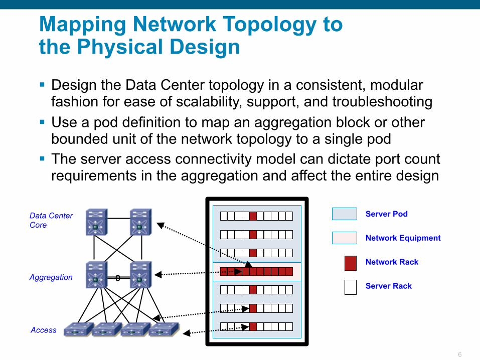
Data Center Core
Aggregation
Access
Server Pod
Network Equipment
Network Rack
Server Rack
Mapping Network Topology tothe Physical Design Design the Data Center topology in a consistent, modular
fashion for ease of scalability, support, and troubleshooting Use a pod definition to map an aggregation block or other
bounded unit of the network topology to a single pod The server access connectivity model can dictate port count
requirements in the aggregation and affect the entire design
7
Traditional Data Center ServerAccess Models End-of-Row (EoR)
High density chassis switch at end or middle ofa row of racks, fewer overall switches
Provides port scalability and local switching, maycreate cable management challenges
Top-of-Rack (ToR)Small fixed or modular switch at the top ofeach rack, more devices to manage
Significantly reduces bulk of cable by keepingconnections local to rack or adjacent rack
Integrated SwitchingSwitches integrated directly into blade server chassis enclosure
Maintaining feature consistency is critical to network management, sometimes pass-through modules are used
8
Impact of New Features and Products On Hierarchical Design forData Center Networks
9
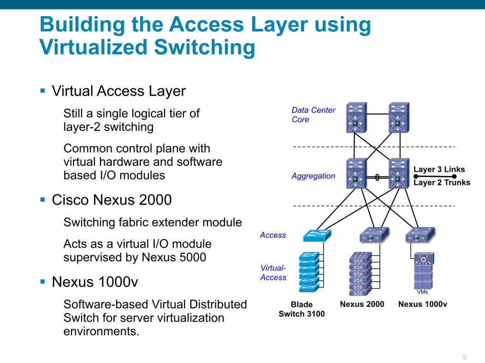
Aggregation
Access
Virtual-Access
Nexus 2000 Nexus 1000v
Data Center Core
Layer 3 LinksLayer 2 Trunks
VMs
BladeSwitch 3100
Building the Access Layer using Virtualized Switching
Virtual Access LayerStill a single logical tier oflayer-2 switching
Common control plane withvirtual hardware and software based I/O modules
Cisco Nexus 2000Switching fabric extender module
Acts as a virtual I/O module supervised by Nexus 5000
Nexus 1000vSoftware-based Virtual Distributed Switch for server virtualization environments.
10
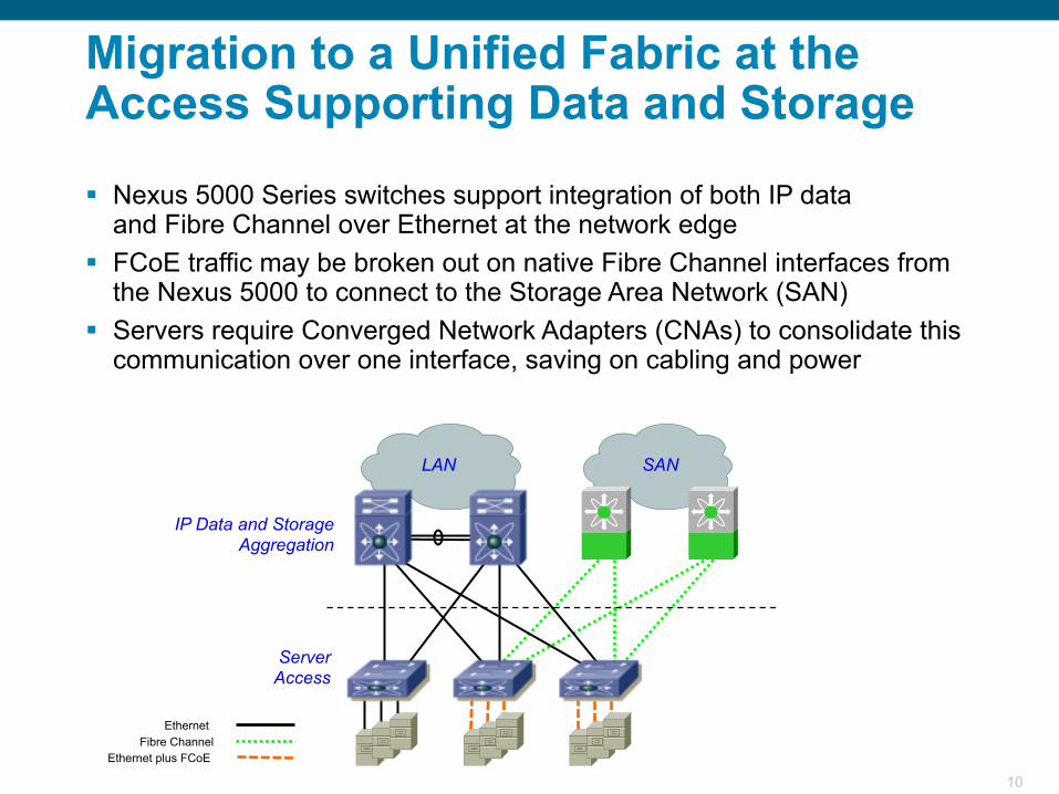
LAN
ServerAccess
SAN
IP Data and Storage Aggregation
Ethernet Fibre Channel
Ethernet plus FCoE
Migration to a Unified Fabric at the Access Supporting Data and Storage
Nexus 5000 Series switches support integration of both IP dataand Fibre Channel over Ethernet at the network edge
FCoE traffic may be broken out on native Fibre Channel interfaces from the Nexus 5000 to connect to the Storage Area Network (SAN)
Servers require Converged Network Adapters (CNAs) to consolidate this communication over one interface, saving on cabling and power
11
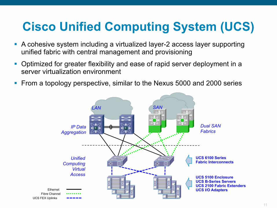
A cohesive system including a virtualized layer-2 access layer supporting unified fabric with central management and provisioning
Optimized for greater flexibility and ease of rapid server deployment in a server virtualization environment
From a topology perspective, similar to the Nexus 5000 and 2000 series
Cisco Unified Computing System (UCS)
LAN
UnifiedComputing
Virtual Access
SAN
IP Data Aggregation
Ethernet Fibre Channel
UCS FEX Uplinks
Dual SANFabrics
UCS 6100 SeriesFabric Interconnects
UCS 5100 EnclosureUCS B-Series ServersUCS 2100 Fabric ExtendersUCS I/O Adapters
12
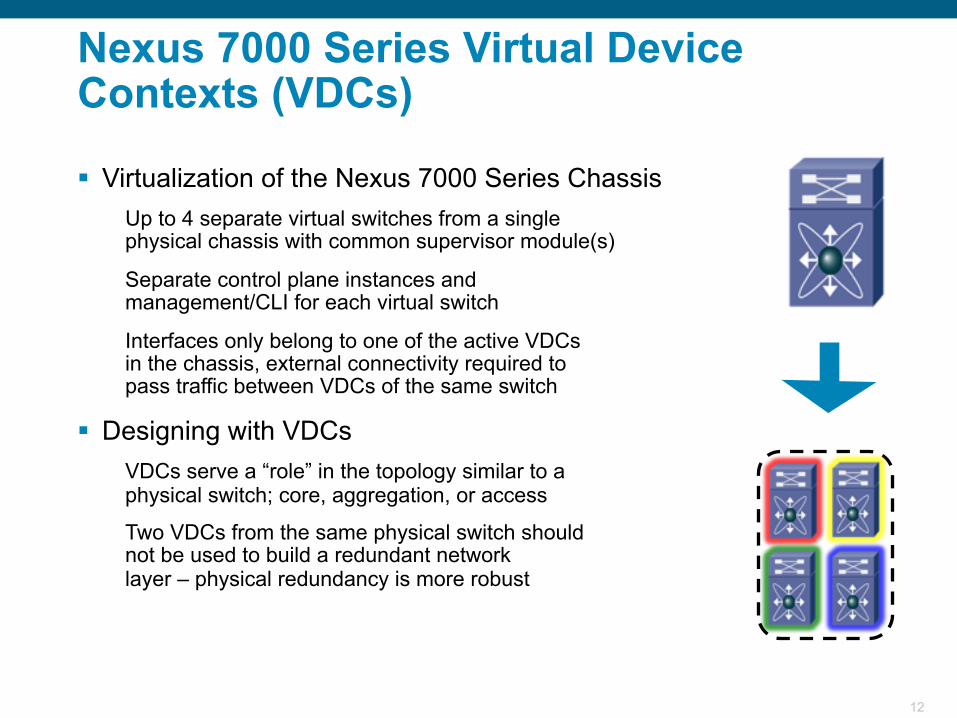
Nexus 7000 Series Virtual Device Contexts (VDCs)
Virtualization of the Nexus 7000 Series ChassisUp to 4 separate virtual switches from a singlephysical chassis with common supervisor module(s)
Separate control plane instances andmanagement/CLI for each virtual switch
Interfaces only belong to one of the active VDCsin the chassis, external connectivity required topass traffic between VDCs of the same switch
Designing with VDCsVDCs serve a “role” in the topology similar to aphysical switch; core, aggregation, or access
Two VDCs from the same physical switch shouldnot be used to build a redundant networklayer – physical redundancy is more robust
13
Core
Aggregation VDC
Access
Sub-AggregationVDC
6500Services Chassis
Enterprise Network
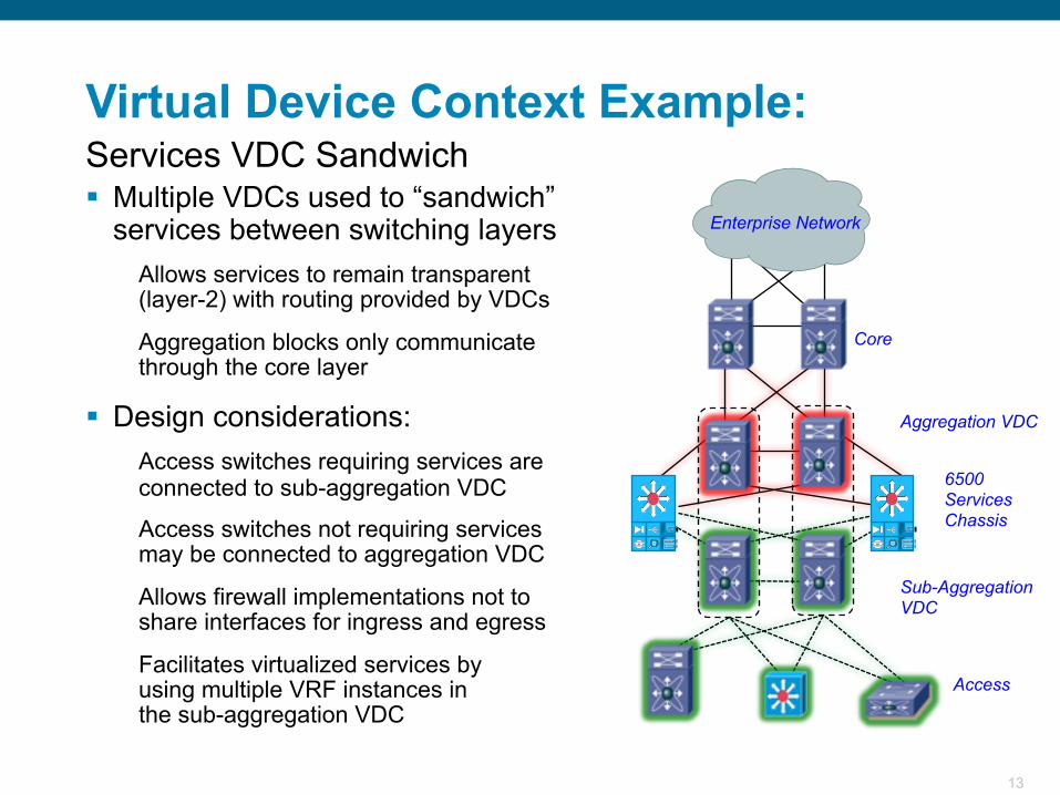
Virtual Device Context Example:
Multiple VDCs used to “sandwich” services between switching layers
Allows services to remain transparent (layer-2) with routing provided by VDCs
Aggregation blocks only communicate through the core layer
Design considerations:Access switches requiring services are connected to sub-aggregation VDC
Access switches not requiring servicesmay be connected to aggregation VDC
Allows firewall implementations not toshare interfaces for ingress and egress
Facilitates virtualized services byusing multiple VRF instances inthe sub-aggregation VDC
Services VDC Sandwich
14
Data Center Service Insertion
15
Data Center Core
Aggregation
Access
Services
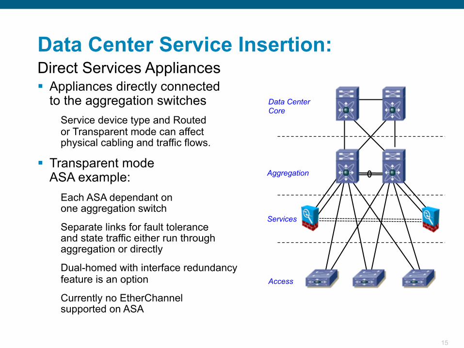
Data Center Service Insertion:
Appliances directly connectedto the aggregation switches
Service device type and Routedor Transparent mode can affectphysical cabling and traffic flows.
Transparent modeASA example:
Each ASA dependant onone aggregation switch
Separate links for fault toleranceand state traffic either run through aggregation or directly
Dual-homed with interface redundancy feature is an option
Currently no EtherChannelsupported on ASA
Direct Services Appliances
16
Data Center Core
Aggregation
Access
Services
Data Center Service Insertion:
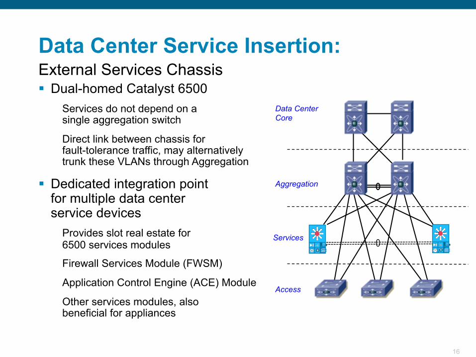
Dual-homed Catalyst 6500Services do not depend on asingle aggregation switch
Direct link between chassis forfault-tolerance traffic, may alternatively trunk these VLANs through Aggregation
Dedicated integration pointfor multiple data centerservice devices
Provides slot real estate for6500 services modules
Firewall Services Module (FWSM)
Application Control Engine (ACE) Module
Other services modules, alsobeneficial for appliances
External Services Chassis
17
Enterprise Network
VLAN 161
VLANs171,172
VLAN 163
VLAN 170
Web Server Farm
VLAN 162
Transparent FWSM Context
TransparentACE Context
AggregationVDC
Services
Sub-AggregationVDC
Access
VLAN 180
Data CenterCore
Client-Server Flow
Using Virtualization and Service Insertion to Build Logical Topologies
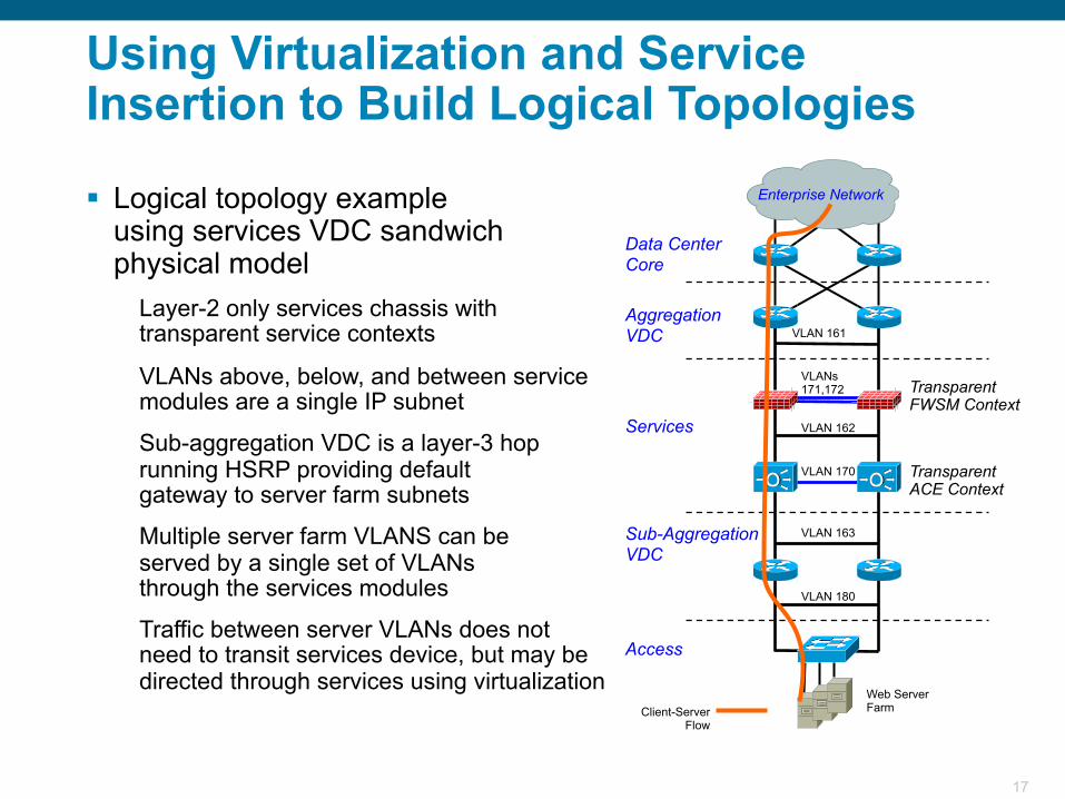
Logical topology exampleusing services VDC sandwich physical model
Layer-2 only services chassis with transparent service contexts
VLANs above, below, and between service modules are a single IP subnet
Sub-aggregation VDC is a layer-3 hop running HSRP providing defaultgateway to server farm subnets
Multiple server farm VLANS can beserved by a single set of VLANsthrough the services modules
Traffic between server VLANs does not need to transit services device, but may be directed through services using virtualization
18
FT VLANs
Enterprise Network
VLAN 161
VLAN 163
FT VLAN
Web/AppServer Farm
Transparent FWSM Contexts
TransparentACE Contexts
VRF Instances
Aggregation VDC
Services
Sub-Agg VDC
Access
VLAN 180
Data Center Core
VLAN 153
VLAN 152
VLAN 181
FT VLANs
FT VLAN
DB ServerCluster
VLAN 151
Client-Server Flow
Server to Server Flow
VLAN 162
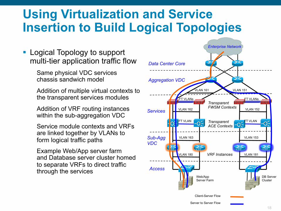
Logical Topology to support multi-tier application traffic flow
Same physical VDC serviceschassis sandwich model
Addition of multiple virtual contexts to the transparent services modules
Addition of VRF routing instances within the sub-aggregation VDC
Service module contexts and VRFs are linked together by VLANs toform logical traffic paths
Example Web/App server farmand Database server cluster homedto separate VRFs to direct traffic through the services
Using Virtualization and Service Insertion to Build Logical Topologies
19
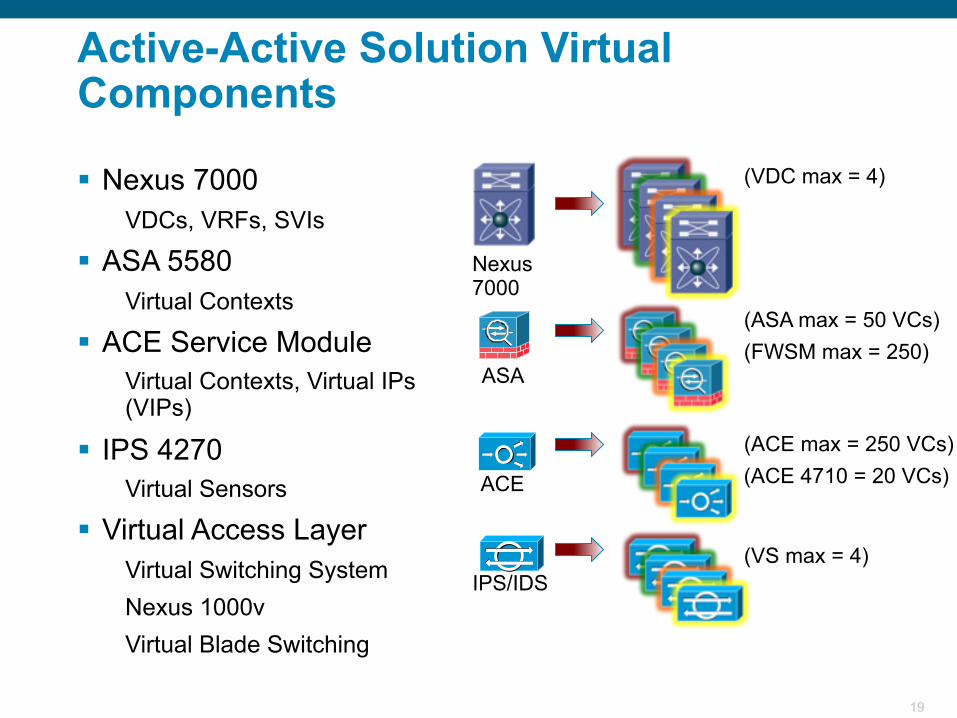
(VDC max = 4)
(ASA max = 50 VCs)(FWSM max = 250)
(ACE max = 250 VCs)
(VS max = 4)
Nexus7000
ASA
ACE
IPS/IDS
(ACE 4710 = 20 VCs)
Active-Active Solution Virtual Components
Nexus 7000VDCs, VRFs, SVIs
ASA 5580Virtual Contexts
ACE Service ModuleVirtual Contexts, Virtual IPs (VIPs)
IPS 4270Virtual Sensors
Virtual Access LayerVirtual Switching SystemNexus 1000vVirtual Blade Switching
20
Layer 3 Features and Best Practices
21
Data Center Core
Enterprise Network
Aggregation
Access
Layer 3
Layer 2
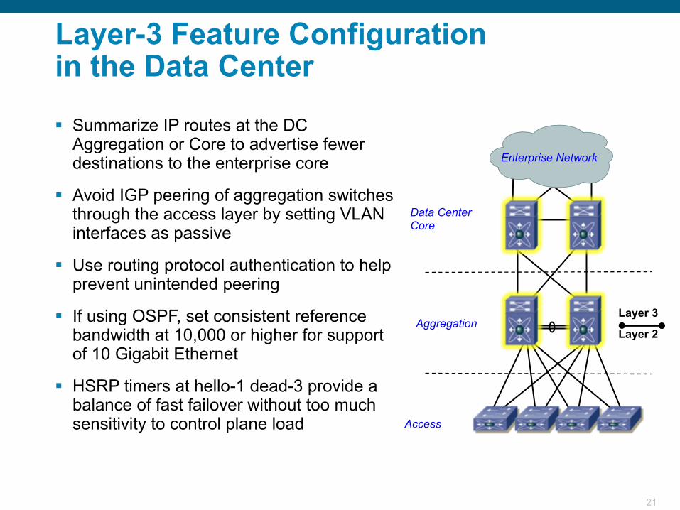
Layer-3 Feature Configurationin the Data Center
Summarize IP routes at the DC Aggregation or Core to advertise fewer destinations to the enterprise core
Avoid IGP peering of aggregation switches through the access layer by setting VLAN interfaces as passive
Use routing protocol authentication to help prevent unintended peering
If using OSPF, set consistent reference bandwidth at 10,000 or higher for support of 10 Gigabit Ethernet
HSRP timers at hello-1 dead-3 provide a balance of fast failover without too much sensitivity to control plane load
22
Common Subnet/VLAN
X
Node 1 Node 2
Node 3 Node 4
What happened to hellos from Node 3? I will wait for the hold timer to expire…
Network “A”
Network “B”
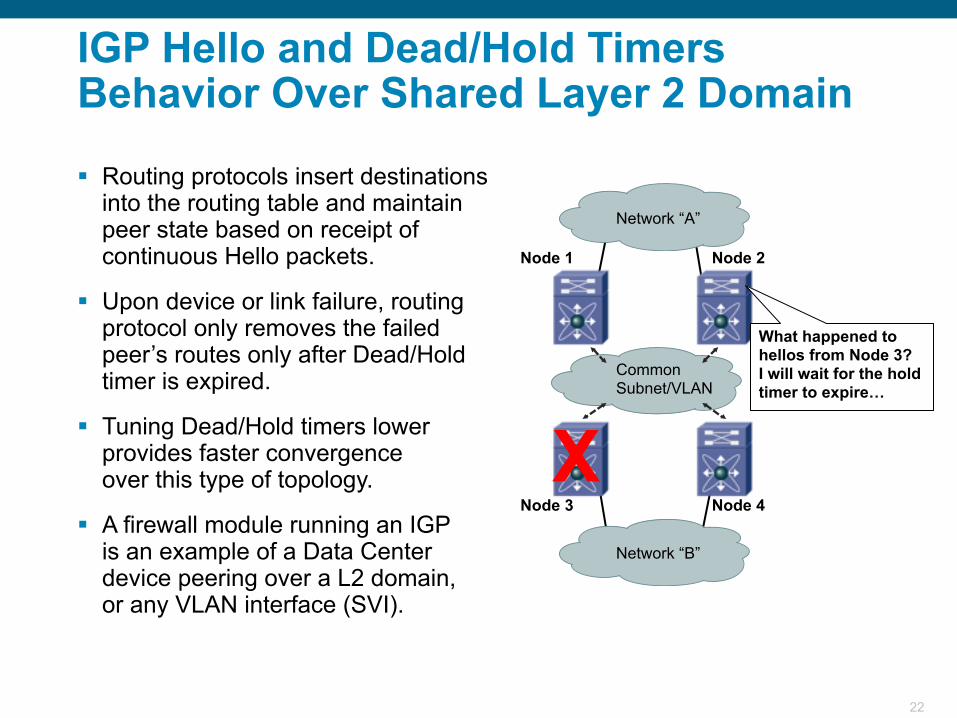
IGP Hello and Dead/Hold TimersBehavior Over Shared Layer 2 Domain
Routing protocols insert destinations into the routing table and maintain peer state based on receipt of continuous Hello packets.
Upon device or link failure, routing protocol only removes the failed peer’s routes only after Dead/Hold timer is expired.
Tuning Dead/Hold timers lower provides faster convergenceover this type of topology.
A firewall module running an IGPis an example of a Data Center device peering over a L2 domain,or any VLAN interface (SVI).
23
Point-to-Point Routed
Links
My one direct link to Node 3 has gone down. I better remove Node 3’s routes from the table immediately…
Node 1 Node 2
Node 3 Node 4
XNetwork “B”
Network “A”
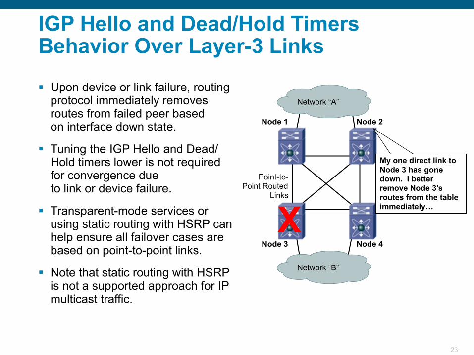
IGP Hello and Dead/Hold TimersBehavior Over Layer-3 Links
Upon device or link failure, routing protocol immediately removes routes from failed peer basedon interface down state.
Tuning the IGP Hello and Dead/Hold timers lower is not required for convergence dueto link or device failure.
Transparent-mode services or using static routing with HSRP can help ensure all failover cases are based on point-to-point links.
Note that static routing with HSRP is not a supported approach for IP multicast traffic.
24
Layer 2 Features, Enhancements and Best Practices
25
N
NN
RN
Type NetworkN
R Root GuardDesignated
Root portAlternate
R
N
N
Aggregation
Access
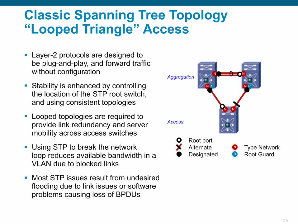
Classic Spanning Tree Topology“Looped Triangle” Access
Layer-2 protocols are designed tobe plug-and-play, and forward traffic without configuration
Stability is enhanced by controllingthe location of the STP root switch,and using consistent topologies
Looped topologies are required to provide link redundancy and server mobility across access switches
Using STP to break the networkloop reduces available bandwidth in a VLAN due to blocked links
Most STP issues result from undesired flooding due to link issues or software problems causing loss of BPDUs
26
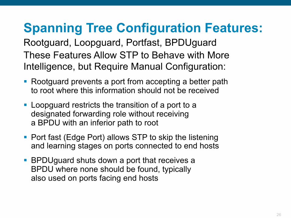
These Features Allow STP to Behave with MoreIntelligence, but Require Manual Configuration: Rootguard prevents a port from accepting a better path
to root where this information should not be received
Loopguard restricts the transition of a port to adesignated forwarding role without receivinga BPDU with an inferior path to root
Port fast (Edge Port) allows STP to skip the listeningand learning stages on ports connected to end hosts
BPDUguard shuts down a port that receives aBPDU where none should be found, typicallyalso used on ports facing end hosts
Spanning Tree Configuration Features:Rootguard, Loopguard, Portfast, BPDUguard
27
Network portN
R Root GuardDesignated port
Root portAlternate port
E Edge port
N
NN
RN R
N
N
E E E
Aggregation
AccessEdge PortsNo BPDUs
Network PortsAll Send BPDUs
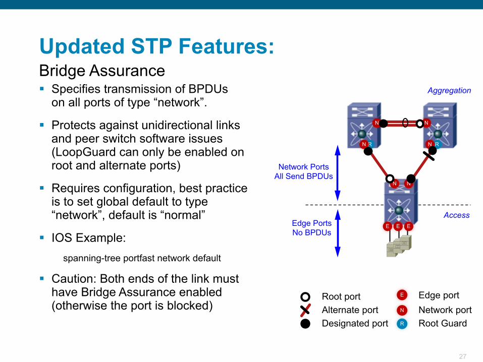
Updated STP Features:Bridge Assurance Specifies transmission of BPDUs
on all ports of type “network”.
Protects against unidirectional linksand peer switch software issues (LoopGuard can only be enabled on root and alternate ports)
Requires configuration, best practiceis to set global default to type“network”, default is “normal”
IOS Example:spanning-tree portfast network default
Caution: Both ends of the link must have Bridge Assurance enabled (otherwise the port is blocked)
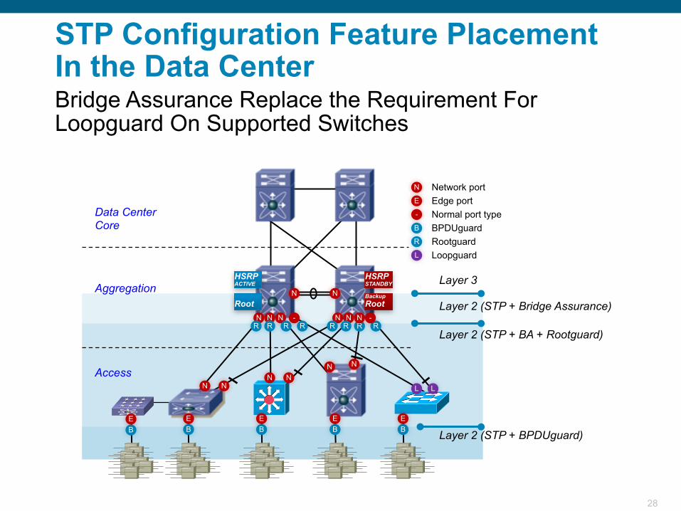
28
Aggregation
Access
Data Center Core B
L
R
N
E
BPDUguard
LoopguardRootguard
Network portEdge port
- Normal port type
B
RR
N N
N N N
N NNN
N N
N N NRRRRRR
--
BE
BE
BE
BE
Layer 3
Layer 2 (STP + Bridge Assurance)
Layer 2 (STP + BA + Rootguard)
Layer 2 (STP + BPDUguard)
L L
E
BackupRoot
HSRPSTANDBY
Root
HSRPACTIVE
STP Configuration Feature PlacementIn the Data CenterBridge Assurance Replace the Requirement For Loopguard On Supported Switches
29
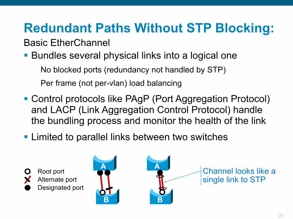
B
A
B
A Channel looks like a single link to STP
Designated port
Root portAlternate port
Bundles several physical links into a logical one No blocked ports (redundancy not handled by STP) Per frame (not per-vlan) load balancing
Control protocols like PAgP (Port Aggregation Protocol) and LACP (Link Aggregation Control Protocol) handle the bundling process and monitor the health of the link
Limited to parallel links between two switches
Redundant Paths Without STP Blocking:Basic EtherChannel
30
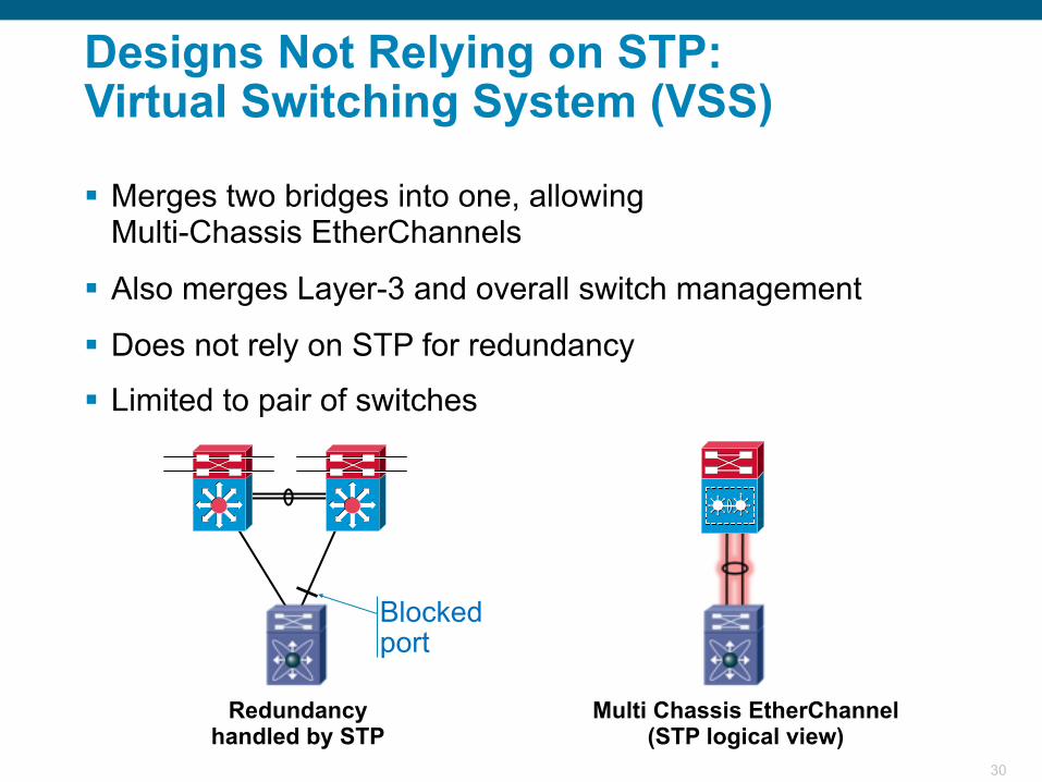
Redundancy handled by STP
Multi Chassis EtherChannel (STP logical view)
Blocked port
Merges two bridges into one, allowingMulti-Chassis EtherChannels
Also merges Layer-3 and overall switch management
Does not rely on STP for redundancy
Limited to pair of switches
Designs Not Relying on STP:Virtual Switching System (VSS)
31
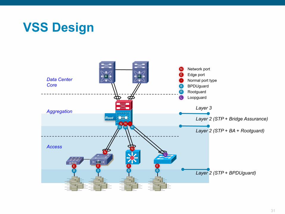
Aggregation
Access
Data Center Core B
L
R
N
E
BPDUguard
LoopguardRootguard
Network portEdge port
- Normal port type
BBE
BE
BE
Layer 3
Layer 2 (STP + Bridge Assurance)
Layer 2 (STP + BA + Rootguard)
Layer 2 (STP + BPDUguard)E
NN
L
RRN N
R-
Root
VSS Design
32
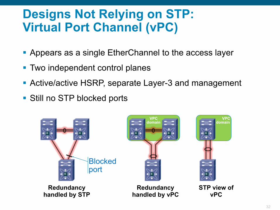
VPCdomain
VPCdomain
Redundancy handled by STP
Redundancy handled by vPC
STP view of vPC
Blocked port
Appears as a single EtherChannel to the access layer
Two independent control planes
Active/active HSRP, separate Layer-3 and management
Still no STP blocked ports
Designs Not Relying on STP:Virtual Port Channel (vPC)
33
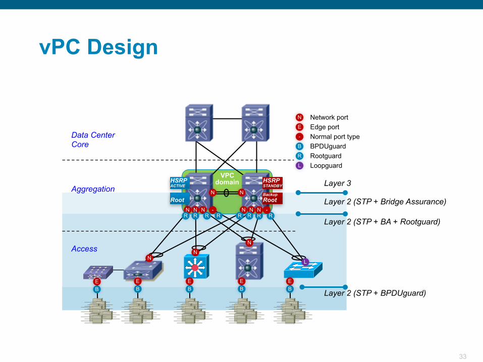
VPCdomain
Aggregation
Access
Data Center Core B
L
R
N
E
BPDUguard
LoopguardRootguard
Network portEdge port
- Normal port type
B
RR
N N
N N N N N NRRRRRR
--
BE
BE
BE
BE E
NN
N
L
Layer 3
Layer 2 (STP + Bridge Assurance)
Layer 2 (STP + BA + Rootguard)
Layer 2 (STP + BPDUguard)
BackupRoot
HSRPSTANDBY
Root
HSRPACTIVE
vPC Design
34
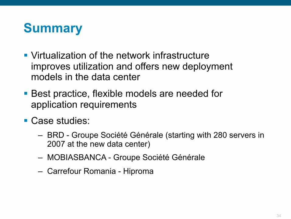
Summary
Virtualization of the network infrastructureimproves utilization and offers new deploymentmodels in the data center
Best practice, flexible models are needed for application requirements
Case studies:– BRD - Groupe Société Générale (starting with 280 servers in
2007 at the new data center)– MOBIASBANCA - Groupe Société Générale
– Carrefour Romania - Hiproma
35
Recommended