BASICS OF THERMAL INSULATION
Vincent Barraud
SOPREMA
Summary
Part 1 - What is thermal conductivity ?
Part 2 - How the thermal conductivity is
measured ?
Part 3 – How to certify a lambda value ?

Part 1 - What is thermal conductivity ?
The common point of
all the insulation
materials !

Fourier's Law is used to express conductive heat transfer :
q = .A.dT / s
Where
q = heat transfer (W/m²)
A = heat transfer area (m2)
= thermal conductivity of material (W/(m.K)
dT = temperature difference across the material (K)
s = material thickness (m)
Part 1 - What is thermal conductivity ?

In International System of Units, thermal conductivity is measured in watts per meter Kelvin (W/(m.K)) and in imperial units thermal conductivity is measured in BTU/(hr.ft.°F).
Other units which are closely related to the thermal conductivity are in common use in the construction and textile industries.
The construction industry makes use of units such as the R-value (resistance) and the U-value (conductivity). Although related to the thermal conductivity of a material used in an insulation product, R and U-values are dependent on the thickness of the product.
Likewise the textile industry has several unit including the tog (1 tog = 0.1 m2.K/W) and the clo which express thermal resistance of a material in a way analogous to the R-values used in the construction industry.
Part 1 - What is thermal conductivity ?

Thermal resistance is the ability of a material to resist to the heat flow. Thermal resistivity is the reciprocal of thermal conductivity and can be expressed as
R = s /
where
R = thermal resistivity (m².K/W)
= thermal conductivity (W/(m.K))
s = material thickness (m)
Part 1 - What is thermal conductivity ?

Thermal transmittance from thermal resistance can be expressed as :
U = 1 / R = 1 / Σ Ri*
where
R = thermal resistivity (m².K/W)
U = overall thermal transmittance (W/m².K)
*Ri (Rmatrix + Rcell gas + Rconvection + Rradiation)
Part 1 - What is thermal conductivity ?
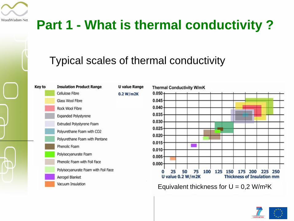
Typical scales of thermal conductivity
Equivalent thickness for U = 0,2 W/m²K
Part 1 - What is thermal conductivity ?

Thermal conductivity is the result of several components :
T = M + G + C + R
M Thermal conductivity in
the matrix
G Thermal conductivity
through cell gas
C Convection in the cell
gas
R Radiation
Part 1 - What is thermal conductivity ? Closed or open Cell Foam Insulation

The most comprehensive resource for an in-depth description of foam insulation thermal performance, and the source for the discussion in this section, is Glicksman, 1994. Total heat transport through foam insulation is typically represented as the superposition of the heat transported via solid conduction, gas conduction, radiation, and convection as shown below. This approximation is valid for low-density materials with modest temperature differences.
qtotal = ( qsolid + qgas )conduction + q radiation + q convection
where: q = heat transfer, W/m².
Part 1 - What is thermal conductivity ? Closed or open Cell Foam Insulation

The solid conduction performance are determined by the foam morphology, which does not change appreciably over the lifetime of the product. The magnitude of the solid conduction in low density foam is shown below :
Part 1 - What is thermal conductivity ?
Closed or open Cell Foam Insulation
q solid conduction:

The remainder of the total conduction is due to gaseous conduction. As gases diffuse in and out of the foam, that mixture changes, and therefore the total thermal conductivity changes. The thermal conductivity of a gas mixture has been characterized by Wassiljewa and Lindsay and Bromley as function of mole fraction, thermal conductivity, viscosity and absolute boiling temperature at one atmosphere pressure:
Part 1 - What is thermal conductivity ?
Closed or open Cell Foam Insulation
q gaz conduction:

The gas conductivity can be decreased by decreasing the pore size of the material. The collisions between the gas molecules and the solid are elastic which transfer small amounts of energy compared to the collisions between gas molecules. The effect on thermal conductivity, from a lowered pressure is strongly dependent of pore size.
Pressure is seen in the denominator for the calculation of the mean free path. A lower pressure gives a longer mean free path which gives a larger Knudsen effect. It is seen that an increase in the mean free path will increase the Knudsen number and thereby decrease the gas conductivity.
Part 1 - What is thermal conductivity ?
Closed or open Cell Foam Insulation
q gaz conduction:
where : δ [m] is the characteristic system size, which can
be interpreted as the distance between two parallel
walls, lmean [m] is the mean free path, λg0
[W/(m·K)] is the conductivity of the gas when
moving freely and β [-] is a constant for the
effectiveness of the energy transfer between the
gas molecules and the solid pore
walls with a value commonly between 1.5 and 2
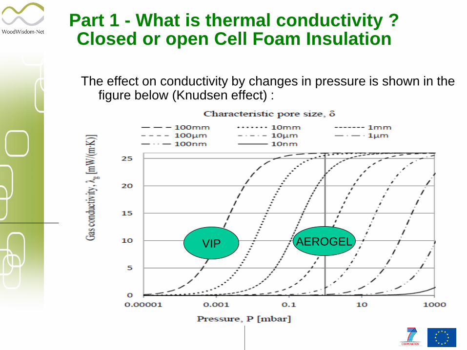
Part 1 - What is thermal conductivity ? Closed or open Cell Foam Insulation
The effect on conductivity by changes in pressure is shown in the figure below (Knudsen effect) :
VIP AEROGEL

The major factor in the net radiation flux is the emission from the solid portions of the foam. The radiation heat transfer is usually modeled using the Rosseland equation. The extinction coefficient is the reciprocal of the photon mean free path. Reducing the mean free path of the photons, by reducing the cell size, is therefore an effective way to reduce this portion of the total heat transport. The radiation transmission from one side of the foam to the other is very small, so that using reflective layers on the exterior foam surfaces has little impact on the radiation heat transport.
Part 1 - What is thermal conductivity ?
Closed or open Cell Foam Insulation
q radiation:

Part 1 - What is thermal conductivity ? Closed or open Cell Foam Insulation
Convection in porous materials can be separated in two cases, the convection inside the pore cells and the convection through the material on a macro scale.
For small pores, the pore cell convection can be neglected, partly because of small temperature differences on the cell walls. That means that the heat transfer through convection often can be neglected for materials with a closed pore system. For materials with open cells, the macro scale convection might have a considerable effect and can thus not be neglected. The macro scale convection is either caused by natural or forced convection. For natural convection the air movement is created by density differences as a consequence of temperature differences, while forced convection is created by a pressure difference due to e.g. wind or fan induced.
q convection:

Natural convection is described by the dimensionless quantity Nusselt number which is a function of the modified Rayleigh number. The relation between the Nusselt number and the Rayleigh number is commonly determined empirically for specific geometries and boundary conditions.
where
ρa [kg/m3] is the density of air,
Cpa [J/(kg·K)] is the specific heat capacity of air,
g [m/s2] is the gravitational acceleration,
a [1/K] is the thermal expansion coefficient of air,
d [m] is the thickness of the porous material,
k [m2] is the permeability,
T+ and T- are the temperatures on the warm and the cold side respectively,
v [m²/s] is the kinematic viscosity,
m [W/(m·K)] is the thermal conductivity of the porous material and
q [W/m²] is the heat flux through the material.
Part 1 - What is thermal conductivity ?
Closed or open Cell Foam Insulation
q convection:

All the products standards for Buildings refer to the EN
12667 to determine the thermal conductivity in CE
but also its conforms to ASTM C518, JIS A1412,
ISO 8301
There is two main tests apparatus :
Heat Flow Meters (HFM)
Guarded Hot Plate device (GHP)
Part 2 - How to measure thermal conductivity?

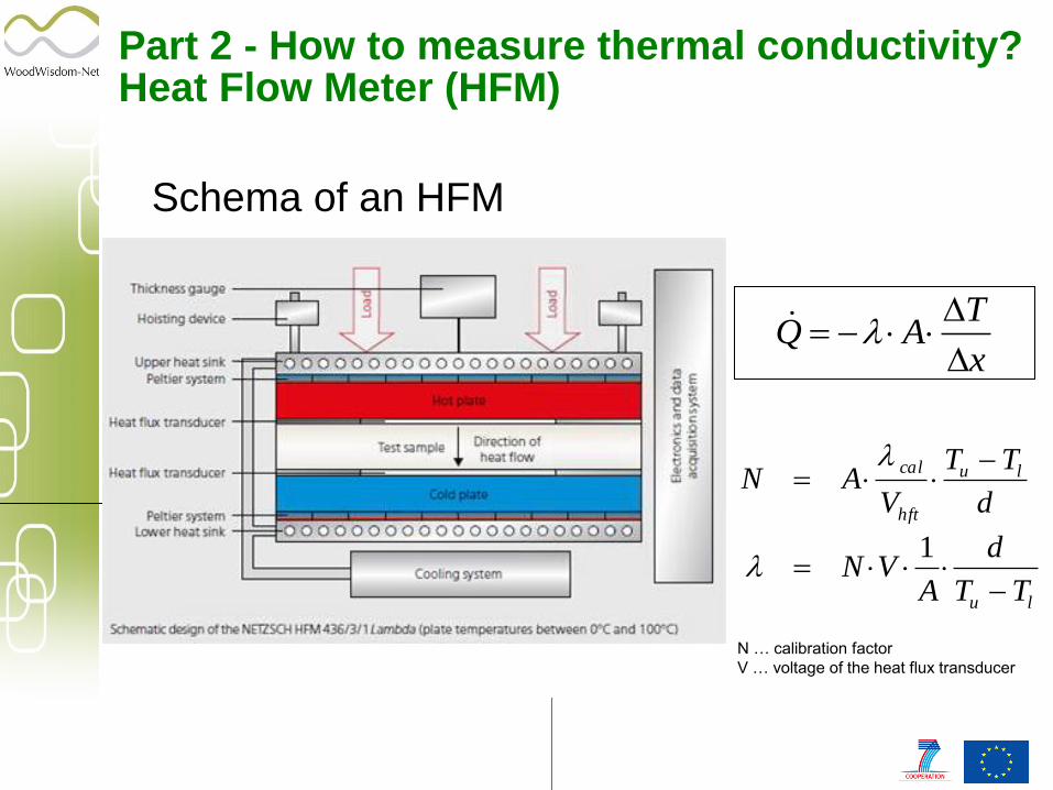
Part 2 - How to measure thermal conductivity? Heat Flow Meter (HFM)
Principle of the measurement :
A sample is placed between two heated plates, set at
different temperatures.
The heat flow (q) through the sample is measured by a
(calibrated) heat flux transducer. After reaching a
thermal equilibrium, the test is done. Only one
sample a is used for the analysis.
The heat flux transducer output is calibrated with a
standard.
x
TAQ
d
TT
VAN lu
hft
cal
lu TT
d
AVN
1
Schema of an HFM
N … calibration factor
V … voltage of the heat flux transducer
Part 2 - How to measure thermal conductivity? Heat Flow Meter (HFM)

The HFM is an easy-to-operate quality control tool with fast testing times of approx. 15 min.
The HFM systems must be calibrated (no absolute test technique) and provide high reproducibility and accuracy (QC).
The HFM works between –20°C and 80°C
The HFM systems work around room temperature.
The HFM systems work under air.
Part 2 - How to measure thermal conductivity? Heat Flow Meter (HFM)

Illustrations of a Netzsch HFM
Part 2 - How to measure thermal conductivity? Heat Flow Meter (HFM)

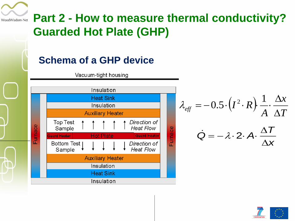
Principle of the measurement
The hot plate and auxiliary heaters (cold plates) are
heated such that a well-defined, user-selectable
temperature difference is set over the sample
thickness. The power input in the hot plate with area
is then measures as soon as thermal equilibrium is
reached. Using the measured temperatures and
power input, the thermal conductivity can be
determined from the stationary heat transfer.
Part 2 - How to measure thermal conductivity?
Guarded Hot Plate (GHP)
x
TAQ
2
T
x
ARIeff
15.0 2
Part 2 - How to measure thermal conductivity?
Guarded Hot Plate (GHP)
Schema of a GHP device

The GHP method is an absolute test technique
No calibration required
The GHP works between –160°C and 700°C (mean sample temperature).
The GHP works under well-defined atmospheres:
vacuum
inert
oxidizing
Part 2 - How to measure thermal conductivity?
Guarded Hot Plate (GHP)

Illustrations of a Netzsch GHP device
Part 2 - How to measure thermal conductivity?
Guarded Hot Plate (GHP)

The declared values RD and D shall be derived from the calculated values R90/90 and 90/90
Part 3 - How to certify a lambda value?
The k values, common to all the products, are given in Table A.1 in the next slide.

Part 3 - How to certify a lambda value?

Two cases depending of the insulation materials :
1 – Thermal insulation products for buildings without influence of the ageing :
EN 13162 – Factory made mineral wool (MW) products
EN 13163 – Factory made expanded polystyrene (EPS) products
EN 13167 – Factory made cellular glass (CG) products
EN 13168 – Factory made wood wool (WW) products
EN 13169 – Factory made cellular glass (CG) products
EN 13171 – Factory made wood fibre (WF) products
EN 15101 – In-situ formed loose fill cellulose (CG) products
Part 3 - How to certify a lambda value?

Procedure :
After conditioning according :
Stabilization at 23°C and 50% relative humidity until constant weight with sometimes 6, 48 or 72 hours at a temperature 50°C or 70°C.
Or in on oven at a temperature at 70°C until constant weight
Thermal resistance and thermal conductivity may also be measured at mean temperatures 10 °C then we obtain directly
the value declared.
Part 3 - How to certify a lambda value?

2 – Thermal insulation products for buildings with an ageing procedure or fixement increment :
EN13164 – Factory made extruded polystyrene (XPS) products
EN13165 - Factory made polyurethane foam (PU) products
EN13166 – Factory made phenolic foam (PF) products
EN 14315-1 and 2 In-situ formed sprayed rigid polyurethane (PU) and polyisocyanurate (PIR) foam products
Part 3 - How to certify a lambda value?

EN 13164 - Factory made extruded polystyrene foam (XPS) products
Slicing (open facing):
Cutting 10mm slices from the product to accelerate gas diffusion.
Storage of 10mm slices at 23 0C for 30-90 days depending on product thickness.
λ- measuring of assembled stuck of slices for aged value at mean temperatures 10 °C.
We obtain directly the value declared by adding a correction of the thermal conductivity due to damaged surface by deducting 0,007 or 0,001 W/(m.K).
Part 3 - How to certify a lambda value?
Ageing procedure (tight facing):
Thermal resistance and thermal conductivity may also be measured at mean temperatures 10 °C after 60 days minimum.
We obtain directly the value declared by adding a conventional correction of 0,001 W/(m.K) to take into account the statistical variation of that production batch.

EN 13165 - Factory made polyurethane (PU) products and EN 14315-1 and 2 In-situ formed sprayed rigid polyurethane (PU) and polyisocyanurate (PIR) foam products
The PU board manufacturer has the choice whether to use heat ageing or fixed increments procedures.
Heat ageing procedure:
Storage the product sample at 70 0C for 175
days
Thermal resistance and thermal conductivity
may also be measured at mean temperatures
10 °C.
We obtain directly the lamdba declared by
adding a safety increment following the type
of facing and blowing agent.
Fixed increments procedure:
Only initial λ value is measured before 8
days after the Production at mean
temperatures 10 °C.
A fixed increment is added for the lambda
declared following the type of facing and
blowing agent.
Part 3 - How to certify a lambda value?

EN13166 - Factory made phenolic foam (PF) products
Heat Ageing procedure
(expanded with a gas) :
Storage at temperatures 70 0C for 175
days or 110 0C for 14 days
Thermal resistance and thermal
conductivity may also be measured at
mean temperatures 10 °C
Then we obtain directly the lambda
declared by adding a safety increment
following the type of facing and blowing
agent.
Slicing procedure (expanded with high molecular weight gas – Conform with CPD) :
Cutting 10mm slices from the product to accelerate gas diffusion
Storage of 10mm slices at 23 0C for 30-90 days depending on product thickness
- measuring of assembled stuck of slices for aged value
Part 3 - How to certify a lambda value?

Part 3 - How to certify a lambda value?
Each country has its own certification label :
Recommended