IEA SHC TASK 60 | PVT SYSTEMS
Basic concepts of PVT collector technologies, applications and markets
Basic concepts of PVT collector technologies, applications and markets SHC Task 60/Report D5
Authors: Manuel Lämmle, Fraunhofer ISE, Germany María Herrando, University of Zaragoza, Spain Glen Ryan, Sunovate, Australia
Contributors: Laetitia Brottier, DualSun, France; Matteo Chiappa, Solink, Italy; Corry de Keizer, TNO,
Netherlands; Alejandro del Amo , Abora, Spain; Alexander Friedrich, 3F Solar, Austria; Antonio Gagliano,
Università di Catania, Italy; Joao Gomes, Solarus, Sweden; Andreas Häberle, HSR Hochschule für Technik
Rapperswil, Switzerland; Eric Hawkins, Speedflex, UK; Danny Jonas, Universität des Saarlandes, Germany;
Korbinian Kramer, Fraunhofer ISE, Germany; Ulrich Leibfried, Consolar, Germany; Alexander Mellor, Naked
Energy, UK; Ilija Nasov, Camel Solar, Macedonia; Thomas Noll, easy-tnt, Germany; Marco Pelligrini,
University of Bologna, Italy; Fernando Perez, Abora, Spain; Markus Pröll, ZAE Bayern e.V., Germany; Niels
Radisch, Ramboll, Denmark; David Sauter, ZHAW, Switzerland; Ionnais Sifnaios, DTU, Denmark; Danjana
Theis, HTW Saar, Germany; Daniel Zenhäusern, SPF, Switzerland
Date: May 1st, 2020
Report number D5 DOI: 10.18777/ieashc-task60-2020-0002
Cover photo: PVT collectors at the New Town Hall Freiburg © Manuel Lämmle/Fraunhofer ISE
The contents of this report do not necessarily reflect the viewpoints or policies of the International Energy Agency (IEA) or its member countries, the IEA Solar Heating and Cooling Technology Collaboration Programme (SHC TCP) members or the participating researchers.

IEA Solar Heating and Cooling Technology Collaboration Programme (IEA SHC)
The Solar Heating and Cooling Technology Collaboration Programme was founded in 1977 as one of the first multilateral technology initiatives ("Implementing Agreements") of the International Energy Agency. Its mission is
“To enhance collective knowledge and application of solar heating and cooling through international collaboration to reach the goal set in the vision of solar thermal energy meeting 50% of low temperature heating and cooling
demand by 2050.”
The members of the IEA SHC collaborate on projects (referred to as Tasks) in the field of research, development, demonstration (RD&D), and test methods for solar thermal energy and solar buildings.
Research topics and the associated Tasks in parenthesis include:
• Solar Space Heating and Water Heating (Tasks 14, 19, 26, 44, 54)
• Solar Cooling (Tasks 25, 38, 48, 53)
• Solar Heat for Industrial or Agricultural Processes (Tasks 29, 33, 49, 62, 64)
• Solar District Heating (Tasks 7, 45, 55)
• Solar Buildings/Architecture/Urban Planning (Tasks 8, 11, 12, 13, 20, 22, 23, 28, 37, 40, 41, 47, 51, 52, 56,
59, 63)
• Solar Thermal & PV (Tasks 16, 35, 60)
• Daylighting/Lighting (Tasks 21, 31, 50, 61)
• Materials/Components for Solar Heating and Cooling (Tasks 2, 3, 6, 10, 18, 27, 39)
• Standards, Certification, and Test Methods (Tasks 14, 24, 34, 43, 57)
• Resource Assessment (Tasks 1, 4, 5, 9, 17, 36, 46)
• Storage of Solar Heat (Tasks 7, 32, 42, 58)
In addition to our Task work, other activities of the IEA SHC include our: Ø International Conference on Solar Heating and Cooling for Buildings and Industry
Ø SHC Solar Academy Ø Solar Heat Worldwide annual statics report
Ø Collaboration with solar thermal trade associations
Country Members Australia
Austria Belgium
Canada China
Denmark European Commission
France
Germany Italy
Netherlands Norway
Portugal Slovakia
South Africa
Spain Sweden
Switzerland Turkey
United Kingdom
Sponsor MembersEuropean Copper Institute ECREEE
International Solar Energy Society PCREEE CCREEE RCREEE
EACREEE SACREEE
For more information on the IEA SHC work, including many free publications, please visit www.iea-shc.org

Preface
The aim of this report is to provide a summary of the current state of the PVT collector technologies, applications,
and markets.
The contents of this report have been used to update and enhance a Wikipedia article on PVT in order to better
inform on PVT a wide audience. Therefore, the main structure and some literal fragments of the current Wikipedia
are reused. Instead of citing the literal fragments of the old Wikipedia article in the main text, we included the old
article in appendix and marked the fragments that were reused.

Contents
Preface .................................................................................................................................................................... iii
Contents.................................................................................................................................................................. iv
1 PVT collectors and their range of operation ................................................................................................. 1
Introduction ................................................................................................................................................. 1
PVT markets ............................................................................................................................................... 2
PVT collector technologies ......................................................................................................................... 2
Classification of PVT collectors ......................................................................................................... 3
PVT liquid collector ........................................................................................................................... 4
PVT air collector ................................................................................................................................ 4
Uncovered PVT collector (WISC)...................................................................................................... 5
Covered PVT collector ...................................................................................................................... 5
Concentrating PVT collector (CPVT) ................................................................................................ 5
PVT applications by temperature range ..................................................................................................... 6
2 A review of PVT applications and systems ................................................................................................... 8
Solar heating systems ................................................................................................................................ 8
Process heat ..................................................................................................................................... 8
Domestic hot water heating............................................................................................................... 8
Space heating ................................................................................................................................... 8
Swimming pool .................................................................................................................................. 9
Heat pump source ............................................................................................................................. 9
Solar cooling and solar combined cooling heating and power systems ..................................................... 9
Solar industrial processes......................................................................................................................... 10
Solar water desalination and solar stills .......................................................................................... 10
Agro-Industrial processes ............................................................................................................... 10
References ............................................................................................................................................... 10
3 Assessment of the market potential of PVT collectors .............................................................................. 14
Appendix 1 - Expert survey on temperature ranges for PVT collector technologies and applications ....... 15
Appendix 2 - Marked version of the original Wikipedia article from 16.03.2019 ............................................. 18
Introduction ............................................................................................................................................... 18
Contents ................................................................................................................................................... 19
PV/T system engineering.......................................................................................................................... 19
System types ............................................................................................................................................ 19
PV/T liquid collector ........................................................................................................................ 19
PV/T air collector ............................................................................................................................. 19
PV/T concentrator (CPVT) .............................................................................................................. 20
See also .................................................................................................................................................... 20
References ............................................................................................................................................... 20
Basic concepts of PVT collector technologies, applications and markets
Page 1
1 PVT collectors and their range of operation
Introduction
Photovoltaic thermal collectors, typically abbreviated as PVT collectors and also known as hybrid solar
collectors, hybrid photovoltaic thermal solar collectors, PV/T collectors or solar cogeneration systems, are power
generation technologies that convert solar radiation into usable thermal and electrical energy. PVT collectors
combine photovoltaic solar cells, which convert sunlight into electricity, with a solar thermal collector, which
transfers the otherwise unused excess heat from the PV module to a heat transfer fluid. By combining electricity
and heat generation within the same component, these technologies can reach a higher overall efficiency than
solar photovoltaic (PV) or solar thermal alone.1
Significant research has gone into developing a diverse range of PVT technologies since the 1970s.2 The
different PVT collector technologies differ substantially in their collector design and heat transfer fluid and address
different applications ranging from low temperature heating and cooling up to high temperature heat above
100 °C.3
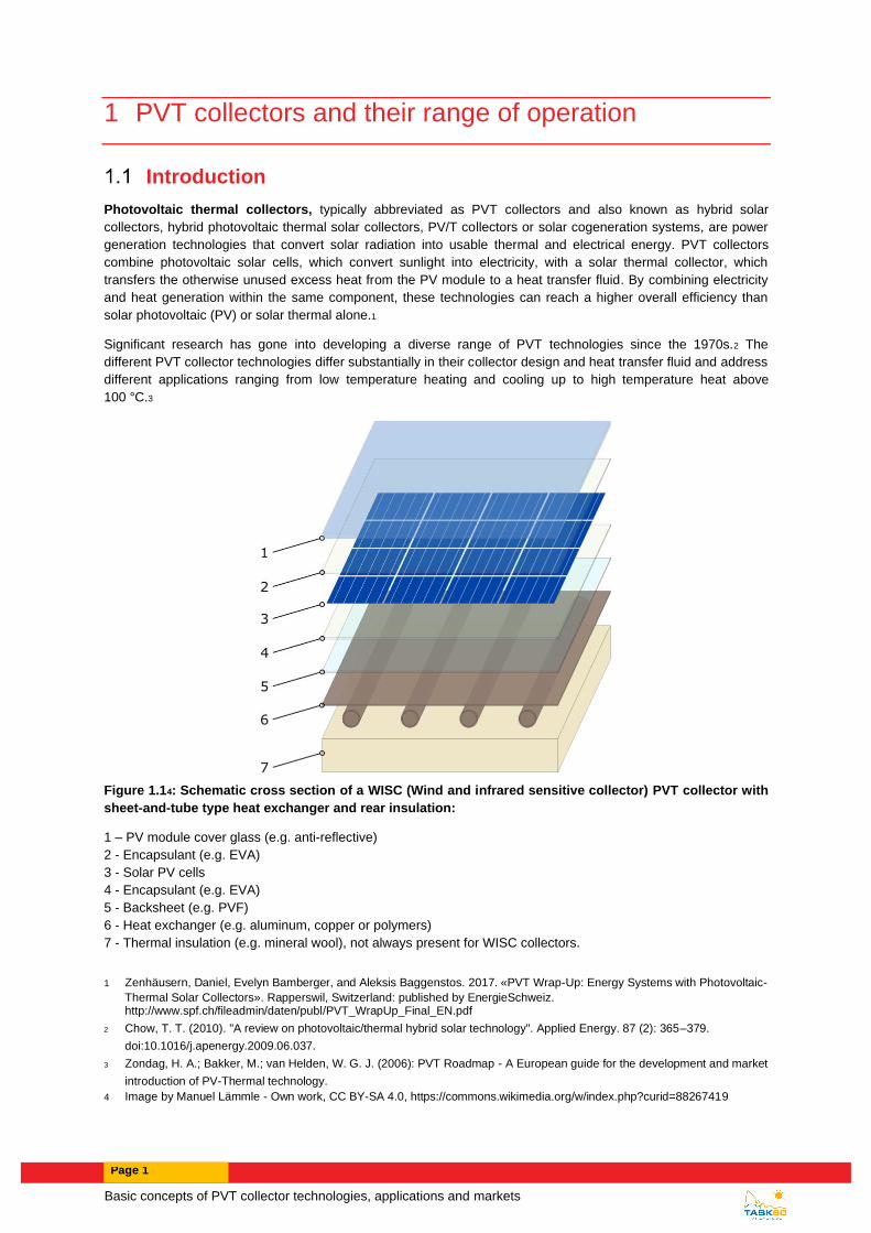
Figure 1.14: Schematic cross section of a WISC (Wind and infrared sensitive collector) PVT collector with
sheet-and-tube type heat exchanger and rear insulation:
1 – PV module cover glass (e.g. anti-reflective)
2 - Encapsulant (e.g. EVA)
3 - Solar PV cells
4 - Encapsulant (e.g. EVA)
5 - Backsheet (e.g. PVF)
6 - Heat exchanger (e.g. aluminum, copper or polymers)
7 - Thermal insulation (e.g. mineral wool), not always present for WISC collectors.
1 Zenhäusern, Daniel, Evelyn Bamberger, and Aleksis Baggenstos. 2017. «PVT Wrap-Up: Energy Systems with Photovoltaic-
Thermal Solar Collectors». Rapperswil, Switzerland: published by EnergieSchweiz. http://www.spf.ch/fileadmin/daten/publ/PVT_WrapUp_Final_EN.pdf
2 Chow, T. T. (2010). "A review on photovoltaic/thermal hybrid solar technology". Applied Energy. 87 (2): 365–379.
doi:10.1016/j.apenergy.2009.06.037.
3 Zondag, H. A.; Bakker, M.; van Helden, W. G. J. (2006): PVT Roadmap - A European guide for the development and market
introduction of PV-Thermal technology.
4 Image by Manuel Lämmle - Own work, CC BY-SA 4.0, https://commons.wikimedia.org/w/index.php?curid=88267419

Page 2
PVT markets
PVT collectors generate solar heat and electricity basically free of direct CO2 emissions and are therefore
regarded as a promising technology to supply renewable electricity and heat and/or cold to buildings and
industrial processes.
Heat is the largest energy end-use. In 2015, the provision of heating for its use in buildings, industrial purposes
and other applications accounted for around 52 % (205 EJ) of the total energy consumed. 5 Of this, over half was
used in the industry and around 46 % in the building sector. While 72 % of the heat was provided by the direct
combustion of fossil fuels, only 7 % of was from modern renewables such as solar thermal, biofuel or
geothermal.6 The low grade heat market up to 150 °C is estimated to be 26.8 % of the worldwide final energy
demand, which is currently serviced by fossil fuels (gas, oil, and coal), electricity and renewable heat. This is the
sum of industry demand 7.1 % (25.5 EJ)7 and building demand 19.7 % (49.0 EJ residential and 13.6 EJ
commercial) 8.
The electricity demand in buildings and industry is expected to grow further due to ongoing electrification and
sector coupling.9 For a significant reduction of carbon emissions, it is essential that the major share of electricity is
sourced from renewable energy sources, such as wind, solar, biomass and water.
The market for renewable heat and electricity is therefore vast, illustrating the market potential of PVT collectors.
The report “Solar Heat Worldwide” assessed the global market of PVT collectors in 2018. According to the
authors, the total area of installed collectors amounted to 1.08 million square meters. Uncovered water collectors
had the largest market share (57 %), followed by air collectors (41 %) and covered water collectors (2 %). The
country with the largest installed capacity was France (41 %), followed by Korea (26 %), China (12 %) and
Germany (10 %).10
PVT collector technologies
PVT collectors combine the generation of solar electricity and heat in a single component, and thus achieve a
higher overall efficiency and better utilization of the solar spectrum than conventional PV modules.
Photovoltaic cells typically reach an electrical efficiency between 15 % and 20 %, while the largest share of the
solar spectrum (65 % - 70 %) is converted into heat, increasing the temperature of PV modules as illustrated in
Figure 2. PVT collectors, on the contrary, are engineered to transfer heat from the PV cells to a fluid. In this way,
this excess heat is made useful and can be utilized to heat water or as a low temperature source for heat pumps,
for example. Thus, PVT collectors make better use of the solar spectrum.1
By co-generating solar electricity and heat in a single component, PVT collectors increase the combined
efficiency and yield an optimized utilization of available space. Especially in densely populated urban areas, PVT
collectors are considered a promising technology for increasing the usage of valuable roof and facade space.
Most photovoltaic cells (e.g. silicon based) suffer from a drop in efficiency with increased cell temperatures. Each
Kelvin of increased cell temperature reduces the efficiency by 0.2 – 0.5 %.3 Removing heat from the PV cells can
5 Collier, Ute (2018), IEA Insights Series 2018: Renewable Heat Policies, Figure 1,
https://webstore.iea.org/download/direct/1030
6 Collier, Ute (2018), IEA Insights Series 2018: Renewable Heat Policies, Figure 2,
https://webstore.iea.org/download/direct/1030
7 Philibert, Cedric 2017, IEA Renewable Energy for Industry From green energy to green materials and fuels, Figure 3,
https://webstore.iea.org/download/direct/1025?fileName=Insights_series_2017_Renewable_Energy_for_Industry.pdf
8 Diana Ürge-Vorsatz, Heating and cooling energy trends and drivers in buildings, Figure 3,
https://doi.org/10.1016/j.rser.2014.08.039
9 IRENA (2019): Global Energy Transformation: A Roadmap to 2050 (2019 Edition). International Renewable Energy Agency,
Abu Dhabi.
https://www.irena.org/-/media/Files/IRENA/Agency/Publication/2019/Apr/IRENA_Global_Energy_Transformation_2019.pdf.
10 Weiss, Werner; Spörk-Dür, Monika (2019): Solar Heat Worldwide - Global Market Development and Trends in 2018 -
Detailed market Figures 2017, https://www.iea-shc.org/Data/Sites/1/publications/Solar-Heat-Worldwide-2019.pdf.

Basic concepts of PVT collector technologies, applications and markets
Page 3
therefore lower their temperature and thus increase the cells’ efficiency. Improved PV cell lifetimes are another
benefit of lower operation temperatures.
The function and energetic benefit of a PVT collector can be described comprehensively by indicating the
electrical and thermal gains in a solar spectrum (Figure 1.2). It is also for this reason, that IEA SHC Task 60 uses
the solar spectrum as part of its logo.
Figure 1.2: Utilization of the electromagnetic solar spectrum by a PVT collector.11
Figure 1.2 is based on the original diagram by Dupeyrat (2011)12, which was updated with recent efficiency data
and detailed optical measurements (compare Lämmle (2018)13):
• Solar irradiance represents the global AM1.5 spectrum according to ASTM G173 - 03(2012) 14 with an
overall irradiance density of G = 1000 W/m².
• The optical losses are calculated based on measured reflectance and transmittance spectra of a PV
module with p-Si solar cells, solar glass and without anti-reflective coating. The optical measurements
were conducted at Fraunhofer ISE with a spectrometer using an Ulbricht sphere.
• The electricity gains are calculated based on the measurements of the spectral response of a c-Si solar
cell with an electrical efficiency of STC = 15 %.
• The heat gains are calculated based on the assumption of a thermal efficiency of th,0 = 61 %, as
typically found in unglazed or glazed PVT collectors with at the operating conditions of Tfluid,mean = Tambient.
• Heat losses account for the remainder of the solar spectrum, as heat losses, and its spectral distribution,
cannot be measured directly.
Accordingly, the solar irradiance represents 100 % of the AM1.5 spectrum, optical losses account for 9 %, heat
losses for 15 %, heat gains for 61 %, and electricity gains for 15 %.
Classification of PVT collectors
11 Image by Manuel Lämmle - Own work, CC BY-SA 4.0, https://commons.wikimedia.org/w/index.php?curid=87526248
12 Dupeyrat, Patrick (2011): Experimental development and simulation investigation of a Photovoltaic-Thermal hybrid solar
collector. INSA de Lyon, France. L’Institut National des Sciences Appliquées de Lyon.
13 Lämmle, Manuel (2018): Thermal management of PVT collectors - development and modelling of highly efficient PVT
collectors with low-emissivity coatings and overheating protection. In: PhD thesis, Fraunhofer ISE, INATECH Albert-
Ludwigs-Universität Freiburg. DOI: 10.6094/UNIFR/16446.
14 ASTM G173 - 03(2012) - Standard Tables for Reference Solar Spectral Irradiances: Direct Normal and Hemispherical on
37° Tilted Surface. https://rredc.nrel.gov/solar//spectra/am1.5/

Page 4
There are a multitude of technical possibilities to combine PV cells and solar thermal collectors. A number of PVT
collectors are available as commercial products, which can be divided into the following categories according to
their basic design and heat transfer fluid:
• PVT liquid collector
• PVT air collector
In addition to the classification by heat transfer fluid, PVT collectors can also be categorized according to the
presence of a secondary glazing to reduce heat losses and the presence of a device to concentrate solar
irradiation.
• Uncovered PVT collector (WISC PVT)
• Covered PVT collector
• Concentrating PVT collector (CPVT)
Moreover, PVT collectors can be classified according to their design, such as cell technology, type of fluid, heat
exchanger material and geometry, type of contact between fluid and PV module, fixation of heat exchanger, or
level of building integration (building integrated PVT (BIPVT) collectors).1,15
The design and type of PVT collectors always implies a certain adaption to operating temperatures, applications,
and giving priority to either heat or electricity generation. For instance, operating the PVT collector at low
temperature leads to a cooling effect of PV cells compared to PV modules and therefore an increase of electrical
power. However, the heat also has to be utilized at low temperatures.
The maximum operating temperatures for most PV modules are limited to less than the maximum certified
operation temperatures (typically 85 °C). Nevertheless, two or more units of thermal energy are generated for
each unit of electrical energy, depending on cell efficiency and system design.
PVT liquid collector
The basic water-cooled design uses channels to direct fluid flow using piping attached directly or indirectly to the
back of a PV module. In a standard fluid-based system, a working fluid, typically water, glycol or mineral oil,
circulates in the heat exchanger behind the PV cells. The heat from the PV cells is conducted through the metal
and is transferred to the working fluid (presuming that the working fluid is cooler than the operating temperature of
the cells).
PVT air collector
The basic air-cooled design uses either a hollow, conductive housing to mount the photovoltaic panels or a
controlled flow of air to the rear face of the PV panel. PVT air collectors either draw in fresh outside air or use air
as a circulating heat transfer medium in a closed loop. The heat transfer properties of air are lower than that of
typically used liquids and therefore requires a proportionally higher mass flow rate than an equivalent PVT liquid
collector. The advantage is that the infrastructure required has lower cost and complexity.
The heated air is circulated into a building HVAC system to deliver thermal energy. Excess heat generated can be
simply vented to the atmosphere. Some versions of the PVT air collector can be operated in a way to cool the PV
panels to generate more electricity and assist with reducing thermal effects on lifetime performance degradation.
A number of different configurations of PVT air collectors exist, which vary in engineering sophistication. PVT air
collector configurations range from a basic enclosed shallow metal box with an intake and exhaust up to
optimized heat transfer surfaces that achieve uniform panel heat transfer across a wide range of process and
ambient conditions.
PVT air collectors can be carried out as uncovered or covered designs.1
15 L. Brottier (2018). Optimisation biénergie d’un panneau solaire multifonctionnel : du capteur aux installations insitu.
Mécanique[physics.med-ph].UniversitéParis-Saclay,2019. https://tel.archives-ouvertes.fr/tel-02133891

Basic concepts of PVT collector technologies, applications and markets
Page 5
Uncovered PVT collector (WISC)
Uncovered PVT collectors, also denoted as unglazed or wind and/or infrared sensitive PVT collectors (WISC),
typically comprise of a PV module with a heat exchanger structure attached to the back of the PV module. While
most PVT collectors are prefabricated units, some products are offered as heat exchangers to be retrofitted to off-
the-shelf PV modules. In both cases, a good and longtime durable thermal contact with a high heat transfer
coefficient between the PV cells and the fluid is essential.16
The rear side of the uncovered PVT collector can be equipped with thermal insulation (e.g. mineral wool or foam)
to reduce heat losses of the heated fluid. Uninsulated PVT collectors are beneficial for operation near and below
ambient temperatures. Particularly uncovered PVT collectors with increased heat transfer to ambient air are a
suitable heat source for heat pump systems. When the temperature in the heat pump’s source is lower than the
ambient, the fluid can be heated up to ambient temperature even in periods without sunshine.
Accordingly, uncovered PVT collectors can be categorized into:
• Uncovered PVT collector with increased heat transfer to ambient air
• Uncovered PVT collector without rear insulation
• Uncovered PVT collector with rear insulation
Uncovered PVT collectors are also used to provide renewable cooling by dissipating heat via the PVT collector to
the ambient air or by utilizing the radiative cooling effect. In doing so, cold air or water is harnessed, which can be
utilized for HVAC applications.
Covered PVT collector
Covered, or glazed PVT collectors, feature an additional glazing, which encloses an insulating air layer between
the PV module and the secondary glazing. This reduces heat losses and increases the thermal efficiency.
Moreover, covered PVT collectors can reach significantly higher temperatures than PV modules or uncovered
PVT collectors. The operating temperatures mostly depend on the temperature of the working fluid. The average
fluid temperature can be between 25 °C in swimming pool applications to 90 °C in solar cooling systems (Figure
3).
Covered PVT collectors resemble the form and design of conventional flat plate collectors or evacuated vacuum
tubes. Yet, PV cells instead of spectrally-selective absorber coatings absorb the incident solar irradiance and
generate an electrical current in addition to solar heat.
The insulating characteristics of the front cover increase the thermal efficiency and allow for higher operating
temperatures. However, the additional optical interfaces increase optical reflections and thus reduce the
generated electrical power. Anti-reflective coatings on the front glazing can reduce the additional optical losses.17
Concentrating PVT collector (CPVT)
A concentrator system has the advantage to reduce the photovoltaic (PV) cell area needed. Therefore it is
possible to use more expensive and efficient PV cells, e.g. multi-junction photovoltaic cells. The concentration of
sunlight also reduces the amount of hot PV-absorber area and therefore reduces heat losses to the ambient,
which improves significantly the efficiency for higher application temperatures.
Concentrator systems often require reliable control systems to accurately track the sun and to protect the PV cells
from damaging over-temperature conditions. However, there are also stationery PVT collector types that use non-
imaging reflectors, such as the Compound Parabolic Concentrator (CPC), and do not have to track the sun.
16 Adam, Mario; Kramer, Korbinian; Fritzsche, Ulrich; Hamberger, Stephan (2014): Abschlussbericht PVT-Norm.
Förderkennzeichen 01FS12035 -„Verbundprojekt: Standardisierung und Normung von multifunktionalen PVT
Solarkollektoren (PVT-Norm)“.
17 Zondag, H.A. (2008): Flat-plate PV-Thermal collectors and systems: A review. In: Renewable and Sustainable Energy
Reviews 12 (4), S. 891–959.

Page 6
Under ideal conditions, about 75 % of the sun's power directly incident upon such systems can be gathered as
electricity and heat. For more details, see the discussion of CPVT within the article for concentrated photovoltaics.
A limitation of high-concentrator (i.e. HCPV and HCPVT) systems is that they maintain their long-term advantages
over conventional c-Si/mc-Si collectors only in regions that remain consistently free of atmospheric aerosol
contaminants (e.g. light clouds, smog, etc.). Power production is rapidly degraded because 1) radiation is
reflected and scattered outside of the small (often less than 1°-2°) acceptance angle of the collection optics, and
2) absorption of specific components of the solar spectrum causes one or more series junctions within the MJ
cells to underperform. The short-term impacts of such power generation irregularities can be reduced to some
degree by including electrical and thermal storage in the system.
PVT applications by temperature range
The range of applications of PVT collectors, and in general solar thermal collectors, can be divided according to
their temperature levels: 18
• low temperature applications up to 50 °C
• medium temperature applications up to 80 °C
• high temperature applications above 80 °C
Low temperature applications include heat pump systems and heating swimming pools or spas up to 50 °C. PVT
collectors in heat pump systems act either as low temperature source for the heat pump evaporator or on the load
side to supply medium temperature heat to a storage tank. Moreover, regeneration of boreholes and ground
source heat exchangers is possible.1 Uncovered PVT collectors with enhanced air-to-water heat exchange can
even comprise the only source of a heat pump system. In combination with a system architecture allowing to store
cold produced with WISC or air collectors, also air conditioning is possible.
Low and medium temperature applications for space heating and domestic hot water provision are found in
buildings, with temperatures from 20 °C to 80 °C. The temperatures of the specific system depend on the
requirements of the heat supply system for domestic hot water (e.g. freshwater station, temperature requirements
for legionella prevention) and for space heating (e.g. underfloor heating, radiators). Moreover, the PVT collector
array can be dimensioned to cover only smaller fractions of the heat demand (e.g. hot water pre-heating), thus
reducing operating temperatures of the PVT collector.
Process heat includes a diverse range of industrial applications with low to high temperature requirements (e.g.
solar water desalination, solar cooling, or power generation with concentrating PVT collectors).19 PVT collector
technologies can be clustered according to their temperature level in the same way: the suitability per
temperature range depends on the PVT collector design and technology. Therefore, each PVT collector
technology features different optimal temperature ranges.
Figure 3 shows typical temperature ranges of both PVT applications and collector technologies. 20 The operating
temperature of the PVT applications ultimately defines the suitability of each type of PVT collector technology.
18 Kalogirou SA (2014). Solar energy engineering: processes and systems. Second Edition. Academic Press.
doi:10.1016/B978-0-12-374501-9.00014-5
19 Wiesenfarth M, Philipps SP, Bett AW, Horowitz K, Kurtz S (2014). Current status of Concentrator Photovoltaic (CPV)
technology
20 Chapter 0 „Expert survey on temperature ranges for PVT collector technologies and applications“ of this report

Basic concepts of PVT collector technologies, applications and markets
Page 7
Figure 1.3: Map of PVT collector technologies and PVT applications per operating temperature.21
Depending on the type of heat transfer fluid, PVT collector technologies are suited for several applications:22
• PVT air collector: space heating systems, agricultural processes (e.g. drying crops);
• PVT liquid collector: Space heating (domestic, industrial), water heating systems, water distillation,
space cooling, food processing systems.
PVT technologies can bring a valuable contribution to the world’s energy mix and should always be considered as
an option for applications delivering renewable electricity, heat or cold.
21 Image by Manuel Lämmle - Own work, CC BY-SA 4.0, https://commons.wikimedia.org/w/index.php?curid=87526793
22 Sathe TM, Dhoble AS. A review on recent advancements in photovoltaic thermal techniques. Renew Sustain Energy Rev
2017;76:645–72. doi:10.1016/j.rser.2017.03.075.
Page 8
2 A review of PVT applications and systems
Author: María Herrando, University of Zaragoza
The different types of PVT collectors have different applications. The following sub-sections summarize the state-
of-the art on the main applications.
The range of applications of PVT water collectors and in general solar thermal collectors can be divided in [1]
(Figure 1.3):
low temperature applications, up to 50 °C;
medium temperature applications, up to 80 °C;
high temperature applications, larger than 80 °C.
Low temperature applications (~27-35°C) include swimming pool heating or spas, while operating temperatures
up to 50 °C are required for space heating via radiant underfloor heating (UFH), or integration with low
temperature heat pumps. For Domestic Hot Water (DHW) provision, a temperature of 60 °C is required to prevent
Legionellosis [2], although afterwards the delivery temperature can be lower depending on the end-user needs
(45-60 °C), for which a mixing device is typically used. These temperatures can be provided with unglazed
collectors in high irradiance climates, or with glass cover flat-plate collectors. For cooling purposes through
refrigeration cycles, usually temperatures larger than 80 °C are required to drive thermally driven cooling cycles
such as absorption chillers. Similarly, high temperatures are required for certain industrial processes. These
temperatures can be achieved in high efficiency flat-plate collector with reduced thermal losses, or with evacuated
flat-plate collectors. Concentrated Solar Power (CSP), solar thermal and PVT systems that achieve higher
temperatures can drive power generation cycles in large plants, usually installed in high solar irradiance locations
for power generation [1,3].
Solar heating systems
PVT collectors simultaneously generate heat and electricity. The hot air generated in PVT air collectors can be
used for space heating, while the hot water generated in PVT water collectors can be used for swimming pool
heating, space heating, or water heating.
Process heat
PVT can be used to produce relatively high temperature for any kind of process heat in industry (pasteurization,
car washing, bottles washing, etc..). Evacuated tube PVT collectors and concentrating collectors are used to
reach high temperatures.
Domestic hot water heating
The main components of a solar system for heating provision are the solar collector array, a thermal energy
transfer circuit (circulation pump, valves, piping and heat exchanger) and a water storage tank. An auxiliary heater
is also required to assist the solar system to provide the required water temperature.
These solar systems can be configured as direct systems, such as thermosiphon systems, in which potable water
is directly heated in the PVT collectors; or as indirect system, where potable water is heated through a heat
exchanger with the hot water circulating in the solar closed loop circuit. Most of the studies found in literature
focus on the supply of domestic hot water (DHW) demand in buildings [4,5,14–16,6–13]. From those, several of
them are based on thermosiphon (natural) circulation [5,11,13] while others use an indirect closed loop system
circulating water by forced convection [7–9,15,16].
Space heating
Regarding PVT collectors for space heating purposes, several authors focus on PVT air collectors [17–19]. For
instance, Kamthania et al. (2011) used a semi-transparent PVT double pass façade to preheat air that could heat
the room air temperature by 5-6 ºC above the ambient. Alternatively, PVT air collectors can also be integrated
with heat pumps to provide space heating in buildings [20,21]. The low density and small heat capacity of air limit

Basic concepts of PVT collector technologies, applications and markets
Page 9
improvements in the PVT air collector performance, although these type of collectors are attractive in applications
where water is limited.
PVT water collectors can also provide space heating [21–24]. The hot water generated by the PVT collectors is
usually collected in a hot water storage tank. This tank is connected through a heat exchanger to the terminal
units of the building heating system, which can be for example fan coils [22], radiant floor heating [24,25]. Usually,
an auxiliary heater is also required to assist the solar system to provide the required water temperature.
Another alternative is to integrate PVT liquid collectors with heat pumps, which can maximise the solar energy
utilization and at the same time enhance the COP of the heat pump [26,27]. Here, the heat produced by the PVT
collectors is used as the source for a heat pump to provide space heating [28]. These systems are classified
based on the integration between the PVT collectors and the heat pumps into direct expansion solar assisted heat
pump (DX-SAHP) and indirect expansion solar assisted heat pump (IDX-SAHP). In the former, the PVT collector
acts as the heat pump evaporator, and thus the cooling fluid circulating through the PVT is usually refrigerant.
Alternatively, in indirect expansion solar assisted heat pump (IDX-SAHP) systems, the PVT collector is not the
evaporator of the HP, and PVT-water collectors such as the commercial ones can be used. There are 3 types of
IDX-SAHP: series, parallel and dual system [26]. Here, the heat transfer medium is typically an antifreeze
solution, water or air.
Swimming pool
Originally solar swimming pool heating was achieved with solar-thermal collector heating systems [29,30], or
solar-assisted heat-pump heating systems with conventional solar-thermal collectors [31,32]. However, similarly
as solar-thermal collectors, hybrid PVT water collectors can be used to meet the heating and power demands of
swimming pools. Recently, there are a few thermo-economic analyses undertaken through transient simulations
and sensitivity analyses performed with TRNSYS software [33–35]. The results from the analysis undertaken in
Naples (Italy) [33] showed that the considered system was not profitable without public funding policies and
became viable only after introducing thermal feed-in tariffs due to the high collector costs. Meanwhile, the analysis
of the PVT system for heat and power provision in Bari (Italy), concluded that the economic savings of the PVT
system were between those of the conventional PV and solar-thermal (evacuated-tube) systems and the system
had a payback time of 13.7 years and a levelised cost of energy of 0.109 €/kWh. One of the main advantages of
PVT systems is the larger CO2 emission reduction potential, by 40–75% than those of conventional solar systems
[34]. PVT collectors can also be integrated with Organic Rankine Cycles (ORC) the provision of heating and
power to swimming pool facilities [35].
Heat pump source
WISC PVT collectors can be used in combination with heat pumps. The collector is delivering heat from solar
radiation and from ambient energy on both sides if the back of the collector is not insulated and exposed to
ambient air.
The efficiency of the thermal energy production is high and can be over 100% when calculated in reference to the
solar energy incident on the plane of the collector since the ambient energy is to be added. This is just because of
the conventional definition of the efficiency.
The efficiency of the PV module in the sandwich of a PVT collector can be higher than that of a PV only module
since the average operating temperature can be lower thanks to the heat pump.
Numerous examples exist and are reported in the report A1 of IEA SHC Task 60.
Cooling can be provided by WISC PVT collectors either directly uring night conditions or indirectly with a
reversible heat pump rejecting the heat through the PVT collector heat exchanger if properly designed for this
purpose.
Solar cooling and solar combined cooling heating and power systems

Page 10
Solar Heating and Cooling (SHC) systems can use the solar radiation to provide heating and/or cooling. PVT
collectors can also be integrated with SHC technologies to generate electricity, heating and/or cooling. There are
studies that integrate concentrated PVT [36–39], PVT air systems [40] and PVT water collectors [22].
For example, the thermal output of the PVT water and CPVT collectors can be integrated with solar thermal
driven cooling units, such as absorption, adsorption or desiccant, for cooling provision [41]. Recent studies have
shown that Coefficient of Performance (COP) of up to 0.8 can be achieved by solar-driven single-stage LiBr-H2O
absorption chillers [42,43]. In this context, other authors [22,44,45] integrated PVT water collectors with
absorption chillers and concluded that this combination has an important potential for energy savings owing to the
generated heat/DHW, cooling and electricity. PVT water collectors integrated with water-to-water heat pumps or
to an adsorption chiller can be used to supply the electricity, space heating and cooling, and domestic hot water
for residential buildings [46], fitness centres and offices [47]. Parabolic dish CPVT collectors reach higher water
temperatures so they can be integrated with double-stage LiBr-H2O absorption chillers which have a higher COP
than single-stage LiBr-H2O absorption chillers, to provide electricity, space heating and cooling and domestic hot
water for a given building [37,38].
Alternatively, PVT refrigerant collectors can also be integrated with heat pump air-conditioning systems, using the
PVT as evaporator [48].
Guo et al. [49] reviewed the utilisation of recovered heat from flat plate PVT for desiccant cooling and
dehumidification that requires a temperature in the range of 50 °C to 60 °C. The review addresses both air and
water PVT collectors and reveals that the outlet fluid temperature from existing PVT demonstrations could almost
match the low temperature required by dehumidification and cooling applications with reasonable electrical and
thermal efficiency.
Solar industrial processes
Solar water desalination and solar stills
A solar still distils water by using the heat of the Sun to evaporate water and collect it purified. However,
conventional single basin passive solar stills are not widely used due to their low yield and low thermal efficiency
(maximum around 30%), which is very dependent on solar irradiation [27]. Hybrid flat-plate PVT collectors can be
integrated with solar stills in a hybrid PVT active solar still [50–52]. The cost of distilled water produced from a
PVT active solar still is higher than for a passive solar still, and the payback period is also higher, but the use of
PVT solar still can be advantageous when electricity is unavailable [53]. More promising results were found for an
active PVT solar still system in New Delhi climatic conditions, with a payback time of 4.2 years [54]. Other
research concluded that the productivity can be increased by coupling the PVT collectors with a storage tank [55].
Alternatively, concentrated PVT (CPVT) collectors can be integrated with an evaporation desalination plant to
generate electricity and simultaneously use the thermal energy to desalinate water [56]. Waste heat recovered
from high CPVT systems can also be used for saline and brackish water desalination with the membrane
distillation technique, which is particularly interesting for isolated inland or coastal regions with high solar
irradiation [57].
Agro-Industrial processes
PVT collectors have been used in large greenhouses as a source of heat in the ground and electricity for the fans.
Evacuated and concentrating collectors can be used in industrial processes where heat over 80 °C is needed.
Applications are very few and not enough documented in 2019.
References
[1] Kalogirou SA. Solar energy engineering: processes and systems. Second Edi. Academic Press; 2014.
doi:10.1016/B978-0-12-374501-9.00014-5.
[2] Hansen J, Sorensen H. IEA SHC Task 35 PV/Thermal Solar Systems. IEA 2006.
[3] Wiesenfarth M, Philipps SP, Bett AW, Horowitz K, Kurtz S. Current status of Concentrator Photovoltaic
(CPV) technology. 2015.
Basic concepts of PVT collector technologies, applications and markets
Page 11
[4] Tse K-K, Chow T-T, Su Y. Performance evaluation and economic analysis of a full scale water-based
photovoltaic/thermal (PV/T) system in an office building. Energy Build 2016;122:42–52.
doi:10.1016/j.enbuild.2016.04.014.
[5] Chow TT, Chan ALS, Fong KF, Lin Z, He W, Ji J. Annual performance of building-integrated
photovoltaic/water-heating system for warm climate application. Appl Energy 2009;86:689–96.
doi:10.1016/j.apenergy.2008.09.014.
[6] Cristofari C, Notton G, Poggi P, Louche A. Modelling and performance of a copolymer solar water heating
collector. Sol Energy 2002;72:99–112. doi:10.1016/S0038-092X(01)00092-5.
[7] Cristofari C, Notton G, Canaletti JL. Thermal behavior of a copolymer PV/Th solar system in low flow rate
conditions. Sol Energy 2009;83:1123–38. doi:10.1016/j.solener.2009.01.008.
[8] Cristofari C, Notton G, Poggi P, Louche A. Influence of the flow rate and the tank stratification degree on
the performances of a solar flat-plate collector. Int J Therm Sci 2003;42:455–69. doi:10.1016/S1290-
0729(02)00046-7.
[9] Hobbi A, Siddiqui K. Optimal design of a forced circulation solar water heating system for a residential unit
in cold climate using TRNSYS. Sol Energy 2009;83:700–14. doi:10.1016/j.solener.2008.10.018.
[10] Kim Y, Thu K, Kaur H, Singh C, Choon K. Thermal analysis and performance optimization of a solar hot
water plant with economic evaluation. Sol Energy 2012;86:1378–95. doi:10.1016/j.solener.2012.01.030.
[11] Bazilian MD, Prasad D. A holistic approach to Photovoltaic/thermal/daylight (PV/T/L) cogeneration. Using
waste heat and light from PV modules for building energy loads. ISES EUROSUN Conf 2000.
[12] Kalogirou SA, Tripanagnostopoulos Y. Hybrid PV/T solar systems for domestic hot water and electricity
production. Energy Convers Manag 2006;47:3368–82. doi:10.1016/j.enconman.2006.01.012.
[13] Chow TT, He W, Ji J. Hybrid photovoltaic-thermosyphon water heating system for residential application.
Sol Energy 2006;80:298–306. doi:10.1016/j.solener.2005.02.003.
[14] Dubey S, Tiwari GN. Analysis of PV/T flat plate water collectors connected in series. Sol Energy
2009;83:1485–98. doi:10.1016/j.solener.2009.04.002.
[15] Herrando M, Markides CN, Hellgardt K. A UK-based assessment of hybrid PV and solar-thermal systems
for domestic heating and power: System performance. Appl Energy 2014;122:288–309.
doi:10.1016/j.apenergy.2014.01.061.
[16] Herrando M, Markides CN. Hybrid PV and solar-thermal systems for domestic heat and power provision
in the UK: Techno-economic considerations. Appl Energy 2016;161:512–32.
doi:10.1016/j.apenergy.2015.09.025.
[17] Tiwari GN, Mishra RK, Solanki SC. Photovoltaic modules and their applications: A review on thermal
modelling. Appl Energy 2011;88:2287–304. doi:10.1016/j.apenergy.2011.01.005.
[18] Kamthania D, Nayak S, Tiwari GN. Performance evaluation of a hybrid photovoltaic thermal double pass
facade for space heating. Energy Build 2011;43:2274–81. doi:10.1016/j.enbuild.2011.05.007.
[19] Kumar R, Rosen MA. A critical review of photovoltaic–thermal solar collectors for air heating. Appl Energy
2011;88:3603–14. doi:10.1016/j.apenergy.2011.04.044.
[20] Affolter P, Eisenmann W, Fechner H, Rommel M, Schaap A, Sorensen H, et al. PVT roadmap: A
European guide for the development and market introduction of PV-Thermal technology. Present 20th Eur
Photovolt Sol Energy Conf Exhib 2005;6:10.
[21] Michael JJ, Iniyan S, Goic R. Flat plate solar photovoltaic-thermal (PV/T) systems: A reference guide.
Renew Sustain Energy Rev 2015;51:62–88. doi:10.1016/j.rser.2015.06.022.
[22] Calise F, Dentice D’Accadia M, Vanoli L. Design and dynamic simulation of a novel solar trigeneration
system based on hybrid photovoltaic/thermal collectors (PVT). Energy Convers Manag 2012;60:214–25.
doi:10.1016/j.enconman.2012.01.025.
[23] Vokas G, Christandonis N, Skittides F. Hybrid photovoltaic – thermal systems for domestic heating and
cooling — A theoretical approach. Sol Energy 2006;80:607–15. doi:10.1016/j.solener.2005.03.011.
[24] Herrando M, Ramos A, Freeman J, Zabalza I, Markides CN. Technoeconomic modelling and optimisation
Page 12
of solar combined heat and power systems based on flat-box PVT collectors for domestic applications.
Energy Convers Manag 2018;175:67–85. doi:10.1016/j.enconman.2018.07.045.
[25] Herrando M, Ramos A, Zabalza I. Cost competitiveness of a novel PVT-based solar combined heating
and power system: Influence of economic parameters and financial incentives. Energy Convers Manag
2018;166:758–70. doi:10.1016/j.enconman.2018.04.005.
[26] Kamel RS, Fung AS, Dash PRH. Solar systems and their integration with heat pumps: A review. Energy
Build 2015;87:395–412. doi:10.1016/j.enbuild.2014.11.030.
[27] Brahim T, Jemni A. Economical assessment and applications of photovoltaic/thermal hybrid solar
technology: A review. Sol Energy 2017;153:540–61. doi:10.1016/j.solener.2017.05.081.
[28] de Keizer C, Bottse J, De Jong M. PVT Benchmark. An overview of PVTmodules on the European market
and the barriers and opportuinties for the Dutch Market. 2017.
[29] Singh M, Tiwari GN, Yadav YP. Solar energy utilization for heating of indoor swimming pool. Energy
Convers Manag 1989;29:239–44. doi:10.1016/0196-8904(89)90027-7.
[30] Ruiz E, Martínez PJ. Analysis of an open-air swimming pool solar heating system by using an
experimentally validated TRNSYS model. Sol Energy 2010;84:116–23.
doi:10.1016/J.SOLENER.2009.10.015.
[31] Tagliafico LA, Scarpa F, Tagliafico G, Valsuani F. An approach to energy saving assessment of solar
assisted heat pumps for swimming pool water heating. Energy Build 2012;55:833–40.
doi:10.1016/J.ENBUILD.2012.10.009.
[32] Chow TT, Bai Y, Fong KF, Lin Z. Analysis of a solar assisted heat pump system for indoor swimming pool
water and space heating. Appl Energy 2012;100:309–17. doi:10.1016/J.APENERGY.2012.05.058.
[33] Buonomano A, De Luca G, Figaj RD, Vanoli L. Dynamic simulation and thermo-economic analysis of a
PhotoVoltaic/Thermal collector heating system for an indoor–outdoor swimming pool. Energy Convers
Manag 2015;99:176–92. doi:10.1016/J.ENCONMAN.2015.04.022.
[34] Wang K, Herrando M, Pantaleo AM, Markides CN. Technoeconomic assessments of hybrid photovoltaic-
thermal vs. conventional solar-energy systems: Case studies in heat and power provision to sports
centres. Appl Energy 2019;254:113657. doi:10.1016/J.APENERGY.2019.113657.
[35] Wang K, Herrando M, Pantaleo AM, Markides CN. Thermodynamic and thermoeconomic assessments of
a PVT- ORC combined heating and power system for swimming pools. HEAT POWERED CYCLES 2018
Conf. Proc., Bayreuth: 2018, p. 531–8.
[36] Mittelman G, Kribus A, Dayan A. Solar cooling with concentrating photovoltaic/thermal (CPVT) systems.
Energy Convers Manag 2007;48:2481–90. doi:10.1016/J.ENCONMAN.2007.04.004.
[37] Buonomano A, Calise F, Palombo A. Solar heating and cooling systems by CPVT and ET solar collectors:
A novel transient simulation model. Appl Energy 2013;103:588–606.
doi:10.1016/J.APENERGY.2012.10.023.
[38] Calise F, Dentice d’Accadia M, Palombo A, Vanoli L. Dynamic simulation of a novel high-temperature
solar trigeneration system based on concentrating photovoltaic/thermal collectors. Energy 2013;61:72–86.
doi:10.1016/J.ENERGY.2012.10.008.
[39] Xu Z, Kleinstreuer C. Concentration photovoltaic–thermal energy co-generation system using nanofluids
for cooling and heating. Energy Convers Manag 2014;87:504–12.
doi:10.1016/J.ENCONMAN.2014.07.047.
[40] Eicker U, Dalibard A. Photovoltaic–thermal collectors for night radiative cooling of buildings. Sol Energy
2011;85:1322–35. doi:10.1016/j.solener.2011.03.015.
[41] Alobaid M, Hughes B, Kaiser J, Connor DO, Heyes A. A review of solar driven absorption cooling with
photovoltaic thermal systems. Renew Sustain Energy Rev 2017;76:728–42.
doi:10.1016/j.rser.2017.03.081.
[42] Bellos E, Tzivanidis C, Antonopoulos KA. Exergetic, energetic and financial evaluation of a solar driven
absorption cooling system with various collector types. Appl Therm Eng 2016;102:749–59.
doi:10.1016/j.applthermaleng.2016.04.032.

Basic concepts of PVT collector technologies, applications and markets
Page 13
[43] Papoutsis EG, Koronaki IP, Papaefthimiou VD. Numerical simulation and parametric study of different
types of solar cooling systems under Mediterranean climatic conditions. Energy Build 2017;138:601–11.
doi:10.1016/J.ENBUILD.2016.12.094.
[44] del Amo A. Solar Trigeneration: a Transitory Simulation of HVAC Systems Using Different Typologies of
Hybrid Panels. J Sustain Dev Energy, Water Environ Syst 2014;2:1–14.
doi:10.13044/j.sdewes.2014.02.0001.
[45] Herrando M, Pantaleo AM, Wang K, Markides CN. Solar combined cooling, heating and power systems
based on hybrid PVT, PV or solar-thermal collectors for building applications. Renew Energy
2019;143:637–47. doi:10.1016/j.renene.2019.05.004.
[46] Calise F, Dentice d’Accadia M, Figaj RD, Vanoli L. A novel solar-assisted heat pump driven by
photovoltaic/thermal collectors: Dyna
mic simulation and thermoeconomic optimization. Energy 2016;95:346–66.
doi:10.1016/J.ENERGY.2015.11.071.
[47] Calise F, Figaj RD, Vanoli L. A novel polygeneration system integrating photovoltaic/thermal collectors,
solar assisted heat pump, adsorption chiller and electrical energy storage: Dynamic and energy-economic
analysis. Energy Convers Manag 2017;149:798–814. doi:10.1016/J.ENCONMAN.2017.03.027.
[48] Fang G, Hu H, Liu X. Experimental investigation on the photovoltaic-thermal solar heat pump air-
conditioning system on water-heating mode. Exp Therm Fluid Sci 2010;34:736–43.
doi:10.1016/j.expthermflusci.2010.01.002.
[49] Guo J, Lin S, Bilbao JI, White SD, Sproul AB. A review of photovoltaic thermal (PV/T) heat utilisation with
low temperature desiccant cooling and dehumidification. Renew Sustain Energy Rev 2017;67:1–14.
doi:10.1016/J.RSER.2016.08.056.
[50] Singh G, Kumar S, Tiwari GN. Design, fabrication and performance evaluation of a hybrid photovoltaic
thermal (PVT) double slope active solar still. Desalination 2011;277:399–406.
doi:10.1016/J.DESAL.2011.04.064.
[51] Singh G, Dwivedi VK, Yadav JK, Tiwari GN. Experimental validation of thermal model of hybrid
photovoltaic thermal (HPVT) double slope active solar still. Desalin Water Treat 2012;45:182–90.
doi:10.1080/19443994.2012.692041.
[52] Dev R, Tiwari GN. Characteristic equation of a hybrid (PV-T) active solar still. Desalination 2010;254:126–
37. doi:10.1016/J.DESAL.2009.12.004.
[53] Kumar S, Tiwari GN. Life cycle cost analysis of single slope hybrid (PV/T) active solar still. Appl Energy
2009;86:1995–2004. doi:10.1016/J.APENERGY.2009.03.005.
[54] Kumar S. Thermal–economic analysis of a hybrid photovoltaic thermal (PVT) active solar distillation
system: Role of carbon credit. Urban Clim 2013;5:112–24. doi:10.1016/J.UCLIM.2013.07.001.
[55] Boubekri M, Chaker A, Cheknane A. Modeling and simulation of the continuous production of an
improved solar still coupled with a photovoltaic/thermal solar water heater system. Desalination
2013;331:6–15. doi:10.1016/J.DESAL.2013.09.027.
[56] Mittelman G, Kribus A, Mouchtar O, Dayan A. Water desalination with concentrating photovoltaic/thermal
(CPVT) systems. Sol Energy 2009;83:1322–34. doi:10.1016/J.SOLENER.2009.04.003.
[57] Ong CL, Escher W, Paredes S, Khalil ASG, Michel B. A novel concept of energy reuse from high
concentration photovoltaic thermal (HCPVT) system for desalination. Desalination 2012;295:70–81.
doi:10.1016/J.DESAL.2012.04.005.

Page 14
3 Assessment of the market potential of PVT collectors
Author: Glen Ryan, Sunovate
Worldwide primary energy consumption is currently sitting just under 14,000 Mtoe and demand is expected to
grow by 58% between now and 2040.23 It has been estimated that this market is currently worth over $5.5 Trillion
USD per year. According to the International Energy Agency, heat is the largest energy end-use24. In simplistic
terms this mean that consumers use the greatest amount of their energy for heating. The provision of heating for
use in homes, industrial purposes and other applications accounts for around 50% of the total energy consumed.
Of this, over half is used in industry, around 46% in the building sector and the remainder in agriculture. Only
about a tenth of this heat is produced from renewables.
The heat market is serviced by wood, gas, coal and renewable etc. The low grade heat market (up to 150 °C) is
estimated to be 27.6% of the worldwide final energy demand so proportionally an estimation of the market value
would be currently around $1.5 Trillion USD per annum. Assuming arbitrarily one third of this market is
addressable by current PVT solutions and the energy is valued at the same replacement cost, then the
addressable market for PVT generated heat is $0.5 Trillion USD per annum. The market is therefore immense.
IRENAs Roadmap to 2050 report25 suggests that electrification is emerging as a key solution for reducing
emissions but only if paired with clean electricity, which increasingly can be sourced at the lowest cost from
renewable energy. The share of electricity in total energy use must increase to almost 50% by 2050, up from 20%
today. Renewables would then make up two-thirds of energy consumption and 86% of power generation.
Renewable electricity paired with deep electrification could reduce CO2 emissions by 60%, representing the
largest share of the reductions necessary in the energy sector.
23 BP Statistical Review of World Energy 2019, 68th edition
24 Collier, Ute (2018), IEA Insights Series 2018: Renewable Heat Policies, https://webstore.iea.org/download/direct/1030
25 IRENA: Global Energy Transformation: A Roadmap to 2050 (2019 Edition). International Renewable Energy Agency, Abu
Dhabi.
https://www.irena.org/-/media/Files/IRENA/Agency/Publication/2019/Apr/IRENA_Global_Energy_Transformation_2019.pdf.
Basic concepts of PVT collector technologies, applications and markets
Page 15
Appendix 1 - Expert survey on temperature ranges for PVT collector technologies and applications
Author: Manuel Lämmle, Fraunhofer ISE
A major challenge in the communication of PVT technology concerns temperature ranges of PVT collector
technologies and PVT applications. Given the wide range of available collectors, each with their respective range
of operating temperatures, and manifold applications, each with their respective temperature requirements, it is
important to understand, which collector type is suitable for which application. An approach based on simulations
of PVT systems and using characteristic operation temperatures was presented by Lämmle et al. (2017)26. Within
IEA SHC Task 60, the same question was raised: which collectors are suitable for which temperatures and
consequently for which system?
The herein presented approach taps into the gathered expertise of the participants of IEA SHC Task 60 from
research and industry. A method similar to the Delphi method was applied for this purpose: all task members
were asked to participate in a survey and estimate operating temperature ranges of different PVT collector
technologies and different PVT applications (Table A.1), based on their individual expert know-how.
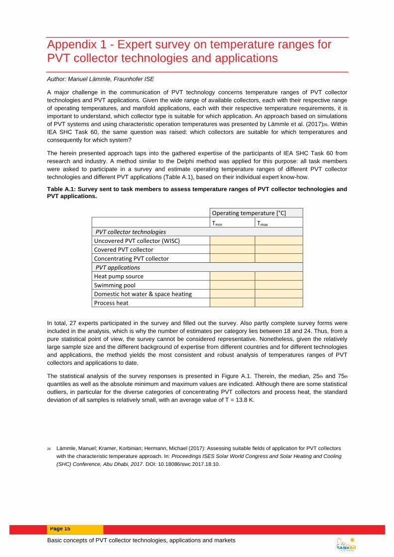
Table A.1: Survey sent to task members to assess temperature ranges of PVT collector technologies and PVT applications.
Operating temperature [°C]
Tmin Tmax
PVT collector technologies
Uncovered PVT collector (WISC)
Covered PVT collector
Concentrating PVT collector
PVT applications
Heat pump source
Swimming pool
Domestic hot water & space heating
Process heat
In total, 27 experts participated in the survey and filled out the survey. Also partly complete survey forms were
included in the analysis, which is why the number of estimates per category lies between 18 and 24. Thus, from a
pure statistical point of view, the survey cannot be considered representative. Nonetheless, given the relatively
large sample size and the different background of expertise from different countries and for different technologies
and applications, the method yields the most consistent and robust analysis of temperatures ranges of PVT
collectors and applications to date.
The statistical analysis of the survey responses is presented in Figure A.1. Therein, the median, 25th and 75th
quantiles as well as the absolute minimum and maximum values are indicated. Although there are some statistical
outliers, in particular for the diverse categories of concentrating PVT collectors and process heat, the standard
deviation of all samples is relatively small, with an average value of T = 13.8 K.
26 Lämmle, Manuel; Kramer, Korbinian; Hermann, Michael (2017): Assessing suitable fields of application for PVT collectors
with the characteristic temperature approach. In: Proceedings ISES Solar World Congress and Solar Heating and Cooling
(SHC) Conference, Abu Dhabi, 2017. DOI: 10.18086/swc.2017.18.10.

Page 16
F:\Wiki\Delphi\Analysis_TemperatureRangesPVT-xlsx.xlsx
-50
-25
0
25
50
75
100
125
150
Min Max Min Max Min Max Min Max Min Max Min Max Min Min
Uncovered PVTcollector (WISC)
Covered PVTcollector
Concentrating PVTcollector
Heat pump source Swimming pool Domest hot water/heating support
Process heat
Min
. an
dm
ax. o
pe
rati
ng
tem
pe
ratu
re[°
C]
Figure A.1: Box plot diagram of the survey responses, boxes represent the 25th and 75th quantile and the median, and the error indicators represent the absolute minimum and maximum values.
Based on the statistical analysis, diagrams mapping PVT collector technologies and applications as function of
the operating temperature can be developed:
• Figure A.2 shows the map based on median values for the minimum and maximum temperatures of the
collector and application ranges, representing a conservative visualization with smaller temperature
ranges.
• Figure A.3 shows the map based on the value of the 25th quantile for the minimum temperature
boundary and the 75th quantile for the maximum temperature boundary. Thus, Figure A.3 portraits a
wider range of operating temperatures than Figure A.2.
• Figure A.4 shows an extended map with a further sub-classification of collector technologies. Answering
the survey, several participants proposed to sub-categorize the collector technologies in order to
visualize differences in the collector design and the corresponding suitability for lower or higher operating
temperatures. The differentiation of temperature steps was done on an arbitrary basis in 10 K steps to
visually incorporate the information of different sub-categories, without starting a new survey.
0°C 10°C 20°C 30°C 40°C 50°C 60°C 70°C 80°C 90°C 100°C
PV
Tap
plic
atio
n
PV
Tco
llect
or
tech
no
logy
Uncovered PVT collector (WISC)
Covered PVT collector
Concentrating PVT collector
Swimming Pool
Domestic hot water & space heating
Process heat
Heat pump source
Operating temperature [°C]
MEAN
Tmin Uncovered PVT collector (WISC) 0
Tmax Uncovered PVT collector (WISC) 40
Tmin Covered PVT collector 20
Tmax Covered PVT collector 80
Tmin Concentrating PVT collector 50
Tmax Concentrating PVT collector 110
Tmin Heat pump source 0
Tmax Heat pump source 23
Tmin Swimming pool 20
Tmax Swimming pool 40
Tmin Domest hot water /heating support 20
Tmax Domest hot water /heating support 80
Tmin Process heat 55
Tmax Process heat 100Boundaries: Mean values
78 107 184
94 105 179
178 77 131
128 97 166
218 44 73
Figure A.2: Map of PVT collector technologies and application as function of the application temperature based on median values for the minimum and maximum temperatures of the collector and application ranges.

Basic concepts of PVT collector technologies, applications and markets
Page 17
-10 0 10 20 30 40 50 60 70 80 90 100 110 120
PV
Tap
plic
atio
n
PV
Tco
llect
or
tech
no
logy
Uncovered PVT collectors (WISC)
Covered PVT collector
Concentrating PVT collector
Swimming Pool
Domestic hot water & space heating
Process heat
Heat pump source
Operating temperature [°C]
Boundaries: P25 value (Tmin) and P75 (Tmax)
Tmin Uncovered PVT collector (WISC) -10
Tmax Uncovered PVT collector (WISC) 50
Tmin Covered PVT collector 5
Tmax Covered PVT collector 85
Tmin Concentrating PVT collector 33
Tmax Concentrating PVT collector 120
Tmin Heat pump source -10
Tmax Heat pump source 25
Tmin Swimming pool 20
Tmax Swimming pool 40
Tmin Domest hot water /heating support 20
Tmax Domest hot water /heating support 80
Tmin Process heat 40
Tmax Process heat 105
Figure A.3: Map of collector technologies and applications with 25th percentile for the mininium boundary and 75th percentile for the maximum boundary
Figure A.4: Extended map featuring further sub-classification of collector technologies. Temperature ranges based on the 25th percentile for the minimum boundary and 75th percentile for the maximum boundary. 27
27 Image by Manuel Lämmle - Own work, CC BY-SA 4.0, https://commons.wikimedia.org/w/index.php?curid=87526793

Page 18
Appendix 2 - Marked version of the original Wikipedia article from 16.03.2019
The summary in chapter 1 is based on the Wikipedia article of PVT collectors “Photovoltaic thermal hybrid solar
collector” in the version from 16.03.2019.28
The original Wikipedia article was not written by Task 60 participants and existed prior to the creation of the task.
The structure and some literal fragments of the original Wikipedia article were reused and recycled for the update
of the article. For a better readability, we avoid citations of the original article. Instead, we include the original
article in the following chapter and mark all fragments in yellow that were taken literally from the original article.
Introduction
Photovoltaic thermal hybrid solar collectors, also known as hybrid PV/T (PVT) or solar cogeneration
systems, are power generation technologies that convert solar radiation into usable thermal and electrical energy.
Such systems combine a solar cell, which converts sunlight into electricity, with a solar thermal collector, which
captures the remaining energy and removes waste heat from the PV module. These technologies can be more
energy efficient overall than solar photovoltaic (PV) or solar thermal alone.[1]
Significant research has gone into developing a diverse range of PV/T technologies since the 1970s.[2]. While
many collector types have been developed for small-scale residential or specific process use, powerful and
highly-efficient systems for industrial and utility-scale applications are also beginning to enter the market.
Collectors co-generating up to 250kW electricity plus 400kW heat, and operating with 80% conversion efficiency,
are commercially available as of 2017.[3]
Schematic of a hybrid (PVT) solar collector:
1 - Anti-reflective glass
2 - EVA-encapsulant
3 - Solar PV cells
4 - EVA-encapsulant
5 - Backsheet (PVF)
6 - Heat exchanger (copper)
7 - Insulation (polyurethane)
28 https://en.wikipedia.org/w/index.php?title=Photovoltaic_thermal_hybrid_solar_collector&oldid=887973945

Basic concepts of PVT collector technologies, applications and markets
Page 19
Contents
• 1 PV/T system engineering
• 2 System types o 2.1 PV/T liquid collector o 2.2 PV/T air collector o 2.3 PV/T concentrator (CPVT)
• 3 See also
• 4 References
PV/T system engineering
Photovoltaic cells suffer from a drop in efficiency with the rise in temperature due to increased resistance. PV/T
systems are engineered to actively capture and carry heat away from the PV cells, thereby cooling the cells and
thus improving their efficiency by lowering resistance.[4] Cell lifetimes also improve at lower temperatures, and the
thermal capture can minimize the urban heat island contribution from the generator.
This is an effective method to maximize total system efficiency and reliability, but causes the thermal component
to under-perform as compared to that achievable with a pure solar thermal collector. That is to say, the maximum
operating temperatures for most PV/T system are limited to less than the maximum cell temperature (typically
below 100°C). Nevertheless, two or more units of heat energy are still generated for each unit of electrical energy,
depending on cell efficiency and system design.
System types
A number of PV/T collectors in different categories are commercially available and can be divided into the
following categories:
• PV/T liquid collector
• PV/T air collector
• PV/Ta Liquid and air collector
• PV/T concentrator (CPVT)
PV/T liquid collector
The basic water-cooled design uses a channel to direct fluid flow using piping of various materials or plates
attached to the back of a PV module. The fluid flow arrangement through the cooling element will determine which
systems the panels are most suited to.
In a standard fluid-based system, a working fluid, typically water, glycol or mineral oil is then piped through these
pipes or plate chillers. The heat from the PV cells is conducted through the metal and absorbed by the working
fluid (presuming that the working fluid is cooler than the operating temperature of the cells). In closed-loop
systems this heat is either exhausted (to cool it), or transferred at a heat exchanger, where it flows to its
application. In open-loop systems, this heat is used, or exhausted before the fluid returns to the PV cells.[5] It is
also possible to disperse nanoparticles in the liquid to create a liquid filter for PV/T applications.[6][7][8] The basic
advantage of this type of split configuration is that the thermal collector and the photovoltaic collector can operate
at different temperatures.
PV/T air collector
The basic air-cooled design uses a hollow, conductive metal housing to mount the photo-voltaic (PV) panels. Heat
is radiated from the panels into the enclosed space, where the air is either circulated into a building HVAC system
to recapture heat energy, or rises and is vented from the top of the structure.
While energy transfer to air is not as efficient as a liquid collector, the infrastructure required has lower cost and
complexity; basically a shallow metal box. Placement of PV panels can be vertical or angled.[9]
Page 20
PV/T concentrator (CPVT)
Main article: Concentrated photovoltaics § Concentrated photovoltaics and thermal
A concentrator system has the advantage to reduce the amount of photovoltaic (PV) cells needed, such that
somewhat more expensive and efficient multi-junction photovoltaic cells can be used that will maximize the ratio
of produced high-value electrical power versus lower-value thermal power. Concentrator systems also often
require reliable control systems to accurately track the sun and to protect the PV cells from damaging over-
temperature conditions. Under ideal conditions, about 75% of the sun's power directly incident upon such systems
can be gathered as electricity and heat. For more details, see the discussion of CPVT within the article for
concentrated photovoltaics.
A limitation of high-concentrator (i.e. HCPV and HCPVT) systems is that they maintain their long-term advantages
over conventional c-Si/mc-Si collectors only in regions that remain consistently free of atmospheric aerosol
contaminants (e.g. light clouds, smog, etc.). Power production is rapidly degraded because 1) radiation is
reflected and scattered outside of the small (often less than 1°-2°) acceptance angle of the collection optics, and
2) absorption of specific components of the solar spectrum causes one or more series junctions within the MJ
cells to under-perform. The short-term impacts of such power generation irregularities can be reduced to some
degree with inclusion of electrical and thermal storage in the system.
See also
• Renewable energy portal
• Energy portal
• Solar air conditioning • Photovoltaic system
References
1. Ahmad Mojiri, Robert A. Taylor, Elizabeth Thomsen, Gary Rosengarten, Spectral beam splitting for efficient conversion of solar energy — A review. In: Renewable and Sustainable Energy Reviews 28, December 2013, Pages 654–663, doi:10.1016/j.rser.2013.08.026
2. Chow, T. T. (2010). "A review on photovoltaic/thermal hybrid solar technology". Applied Energy. 87 (2): 365–379. doi:10.1016/j.apenergy.2009.06.037.
3. "RayGen". 4. S.A. Kalogirou, Y. Tripanagnostopoulos (30 January 2006). These systems are most often used for
domestic hot water (DHW) and electricity production 5. Y. Tripanagnostopoulos, M. Souliotis, R. Battisti, A. Corrado "APPLICATION ASPECTS OF HYBRID
PV/T SOLAR SYSTEMS" http://www.ecn.nl/fileadmin/ecn/units/egon/pvt/pdf/ises03_lca.pdf 6. Taylor, R.A.; Otanicar, T.; Rosengarten, G. (2012). "Nanofluid-based optical filter optimization for PV/T
systems". Light: Science & Applications. 1 (10): e34. Bibcode:2012LSA.....1E..34T. doi:10.1038/lsa.2012.34.
7. Taylor, R.A.; Otanicar, T; Herukerrupu, Y; Bremond, F; Rosengarten, G; Hawkes, E; Jiang, X.; Coulombe, S (2013). "Feasibility of nanofluid-based optical filters". Applied Optics. 52 (7): 1413–1422. Bibcode:2013ApOpt..52.1413T. doi:10.1364/AO.52.001413. PMID 23458793.
8. Otanicar, T.P.; Taylor, R. A.; Telang, C. (2013). "Photovoltaic/thermal system performance utilizing thin film and nanoparticle dispersion based optical filters". Journal of Renewable and Sustainable Energy. 5 (3): 033124. doi:10.1063/1.4811095.
9. "PV Thermal". Solarwall. Retrieved 15 February 2017.
Recommended


![Solar Energy for Industrial Rooftops: An Economic and ... · Solar Thermal ST [2] Photovoltaic PV [1] 2 Compact linear Fresnel Collector [3] PVT Collector [4] Solar Energy for Industrial](https://img.pdfslide.us/doc/110x75/5e42a20e57f4800ae0102b77/solar-energy-for-industrial-rooftops-an-economic-and-solar-thermal-st-2-photovoltaic.jpg)