UNIVERSITI TEKNOLOGI MALAYSIA
MODELLING AND VIBRATION CONTROL OF PIEZOELECTRIC
ACTUATOR
BASHIR BALA MUHAMMAD
.
MODELING AND VIBRATION CONTROL OF PIEZOELECTRIC
ACTUATOR
JUNE 2015
Faculty of Electrical Engineering
Universiti Teknologi Malaysia
A project report submitted in partial fulfilment of the requirements for the award
of the degree of Masters of Engineering
(Electrical-Mechatronics & Automatic Control)
BASHIR BALA MUHAMMAD

iii
This project is dedicated to my beloved late mother Gambo, late father Bala
Muhammad, my brothers my sisters for their encouragement and blessing, support
and caring.
DEDICATION

iv
All praises due to Allah (S.W.A). Peace and blessings upon His messenger, Prophet
Muhammad Sallallahu alaihi wasallam.
Great appreciation to my late father and mother, my late sister Maryam Bala,
my late sister Bilkisu Bala Muhammad, my elder sister Aisha (Asabe), Mahe Bala,
Nasir Bala, Jadidu Bala, Ladidi Bala, Sunusi Bala, Amina Bala, Bilki Bala, Zainab
Bala, Hauwa Bala, Aminu Bala, Mannir Bala and Murtala Bala.
I wholeheartedly acknowledge the great effort and guide from my supervisor:
Dr Mohd Ridzuan bin Ahmad who spared time, energy and resources for the
realization of this research.
Thanks to my family, lecturers, friends and colleagues for their relentless
support, which actively contributed to my success. Great appreciation goes to Md.
Habibur Rahman for the enormous effort towards the completion of this work.
ACKNOWLEDGEMENT
v
The piezoelectric actuator is a voltage spring system that behaves in similar
characteristic to mechanical mass spring system. It converts electrical signal to
physical displacement. The displacements profile of the piezoelectric actuator shifts
due to hysteresis and creep during actuation. Static models of piezoelectric actuator
were developed with different equations in the past. However, static (non-dynamic)
piezoelectric actuator models were not represented by single transfer function.
Furthermore, the modelling of dynamic (vibrating) piezoelectric actuator was not
considered. In this work, we presented the behaviour of the piezoelectric actuator in
terms of mechanical displacement from applied electric potential. The transfer
function mathematical model was generated representing the actuator characteristics.
The vibration model that can vibrate at desired frequency of the actuator was also
developed. The models were developed by system identification from experimental
results. A high resolution microscope together with the image processing technique
was used to obtain the system characteristics. Simulation using Matlab simulink was
used to validate the experiment (The hysteresis was reduced by 90 % and the vibration
was reduced to 97 %.). These models can be used to develop the controller for
controlling vibration profile. It can also be used for desired micro actuation. It can also
be used for desired micro actuation.
ABSTRACT
vi
Penggerak piezoelektrik ialah satu sistem spring voltan yang mempunyai ciri
yang sama dengan sistem spring jisim mekanikal. Ia menukarkan isyarat elektrik
kepada perpindahan fizikal. Profil perpindahan penggerak piezoelektrik beranjak
disebabkan oleh histeresis dan rayapan semasa pergerakan. Sebelum ini, model statik
penggerak piezoelektrik telah dibuat menggunakan persamaan yang berlainan.
Walaubagaimanapun model statik (bukan dinamik) penggerak piezoelektrik tersebut
tidak diwakili oleh fungsi perpindahan tunggal seterusnya. Permodelan penggerak
piezoelektrik dinamik (getaran) tidak dipertimbangkan. Dalam hal ini, kelakuan
penggerak piezoelektrik ditunjukkan dalam segi perpindahan mekanikal daripada
potensi elektrik yang diaplikasikan. Perpindahan fungsi model matematik tersebut
dihasilkan bagi mawakili ciri-ciri penggerak. Model getaran yang boleh bergetar pada
frekuensi penggerak yang diinginkan juga telah dibuat. Model tersebut telah dihasilkan
dengan identifikasi sistem daripada hasil eksperimen. Mikroskop yang mempunyai
resolusi tinggi dan juga teknik pemprosesan gambar telah digunakan bagi
mendapatkan ciri-ciri sistem tersebut. Simulasi telah dijalankan menggunakan Matlab
& Simulink bagi mengesahkan eksperimen tersebut (Histeresis telah dikurangkan
sebanyak 90 % dan gerakan juga telah dikurangkan kepada 97 %). Model-model ini
boleh digunakan untuk menghasilkan pengawal bagi mengawal profil getaran. Selain
itu, ia juga boleh digunakan untuk gerakan mikro yang diinginkan.
ABSTRAK
vii
TABLE OF CONTENTS
CHAPTER
TITLE PAGE
DECLARATION ii
DEDICATION iii
ACKNOWLEDGEMENT iv
ABSTRACT v
ABSTRAK vi
TABLE OF CONTENTS vii
LIST OF TABLES xi
LIST OF FIGURES xii
LIST OF ABBREVATIONS xvii
LIST OF APPENDICES xviii
1 INTRODUCTION
1.1 Introduction 1
1.2 Background of the Study 6
1.3 Problem Statement 8
1.4 Objectives 8
1.5 Scopes of the Study 9
1.6 Significances and Original Contributions of the Study 9
1.7 Project Outline 9

viii
2 LITERATURE REVIEW
2.1 INTRODUCTION 11
2.2 Physics Based Model 11
2.3 Vibration Control of Non-flexible Structure 15
2.4 Vibration Control of Flexible Structure 16
2.5 Modeling of Actuator 17
2.6 Summary 17
3 METHODOLOGY
3.1 Introduction 18
3.2 System Identification 23
3.3 Hysteresis Model 23
3.4 Vibration Model 24
3.5 Proportional Integral and Derivative (PID) Controller 24
3.6 Hysteresis Control 26
3.7 Vibration Control 27
3.8 Summary 29
4 RESULTS AND DISCUSSIONS
4.1 Introduction 30
4.2 Results 30
4.2.1 Table of Result 31
4.2.2 System Identification 33
4.3 Transfer Function Model 36
4.3.1 Simulation Results 38
4.4 Comparison between the Actual Model and Estimated Model 40
ix
4.5 Experiment to Determine Vibration Model of Piezoelectric
Actuator 42
4.6 Operational Amplifier Circuit 45
4.7 Experimental Result 46
4.8 Vibration Transfer Function Model 48
4.9 Simulation Result 50
4.10 Comparison between Actual and Simulated Model 51
4.11 Hysteresis Model Stability 52
4.12 Vibration Model Stability 52
4.13 Controllability and Observability of Hysteresis Model 52
4.14 Controllability and Observability of Vibration Model 53
4.15 Controller 54
4.16 Hysteresis Control 55
4.17 Vibration Control 56
4.18 Comparison between the Hysteresis with Controller and the
Hysteresis without Controller 58
4.19 Comparison of Vibration Model with PID controller and the one
without Controller 60
4.20 Comparison of Vibration Model with PID and without PID using
Pulse Generator 61
4.21 Summary 62
5 CONCLUSION
5.1 Overview 63
5.2 Hysteresis Model Conclusion 63
5.3 Vibration Model 64
5.4 Summary 64
5.5 Recommendation 64

x
REFERENCES 66
Appendices A-B 69-72
xi
LIST OF TABLES
TABLE NO.
TITLE PAGE
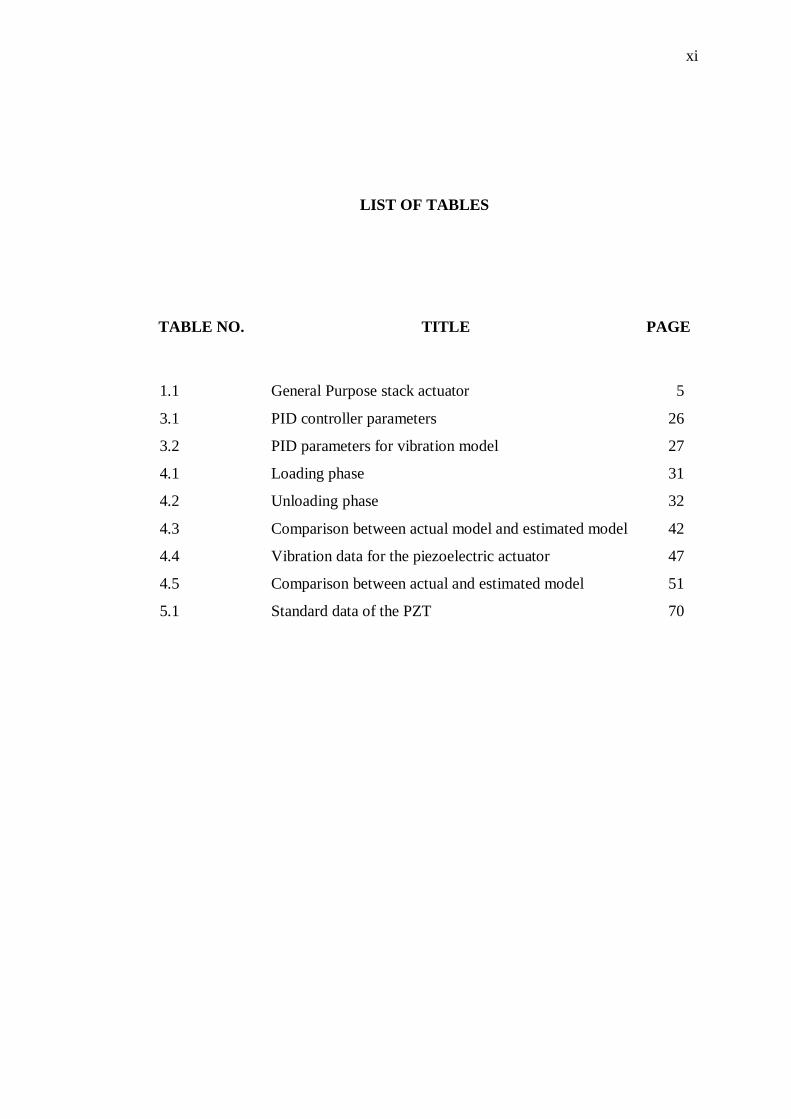
1.1 General Purpose stack actuator 5
3.1 PID controller parameters 26
3.2 PID parameters for vibration model 27
4.1 Loading phase 31
4.2 Unloading phase 32
4.3 Comparison between actual model and estimated model 42
4.4 Vibration data for the piezoelectric actuator 47
4.5 Comparison between actual and estimated model 51
5.1 Standard data of the PZT 70
xii
LIST OF FIGURES
FIGURE NO.
TITLE PAGE
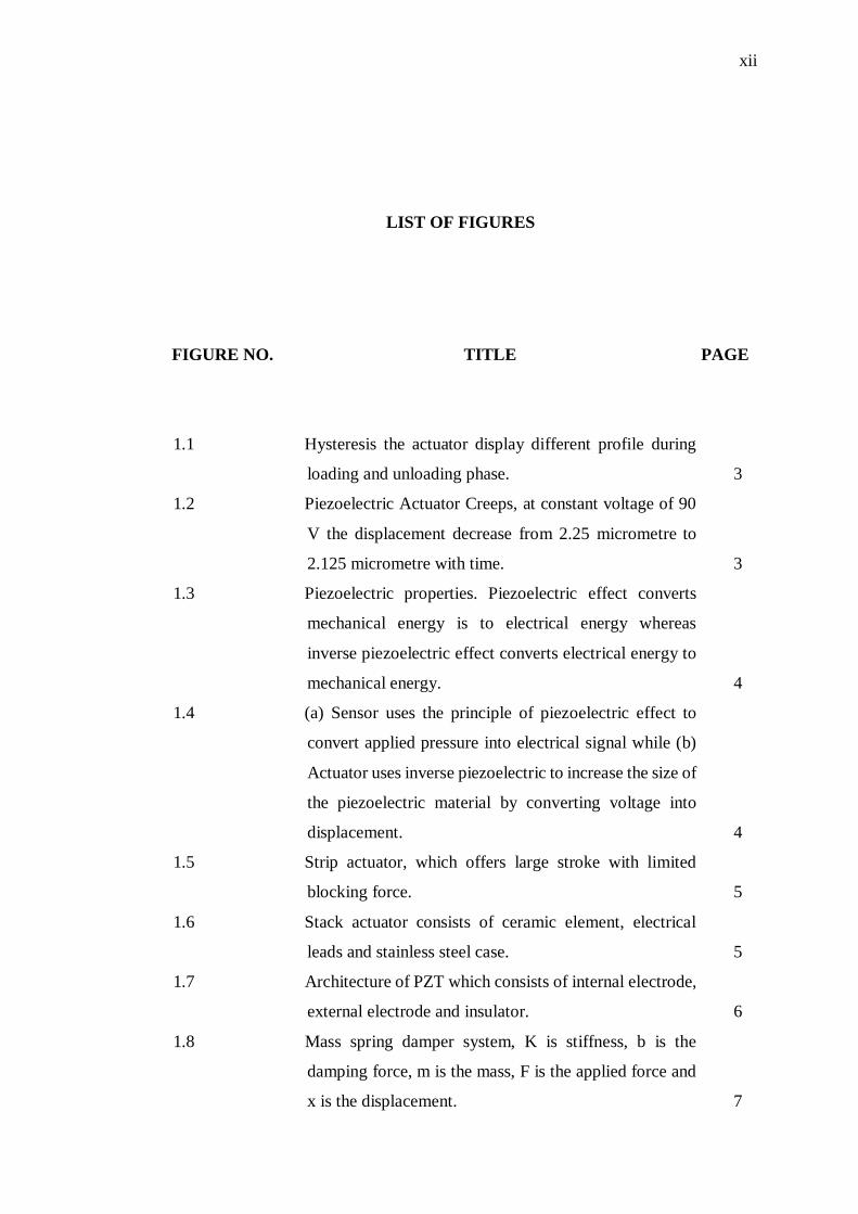
1.1 Hysteresis the actuator display different profile during
loading and unloading phase. 3
1.2 Piezoelectric Actuator Creeps, at constant voltage of 90
V the displacement decrease from 2.25 micrometre to
2.125 micrometre with time. 3
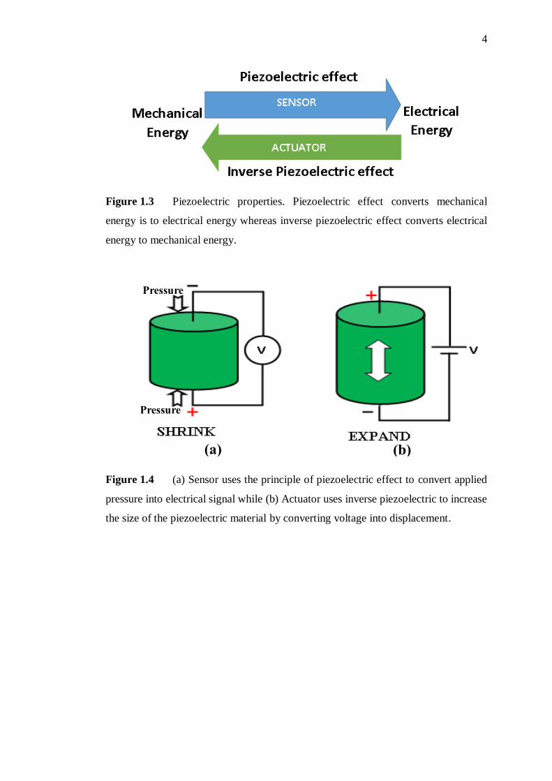
1.3 Piezoelectric properties. Piezoelectric effect converts
mechanical energy is to electrical energy whereas
inverse piezoelectric effect converts electrical energy to
mechanical energy. 4
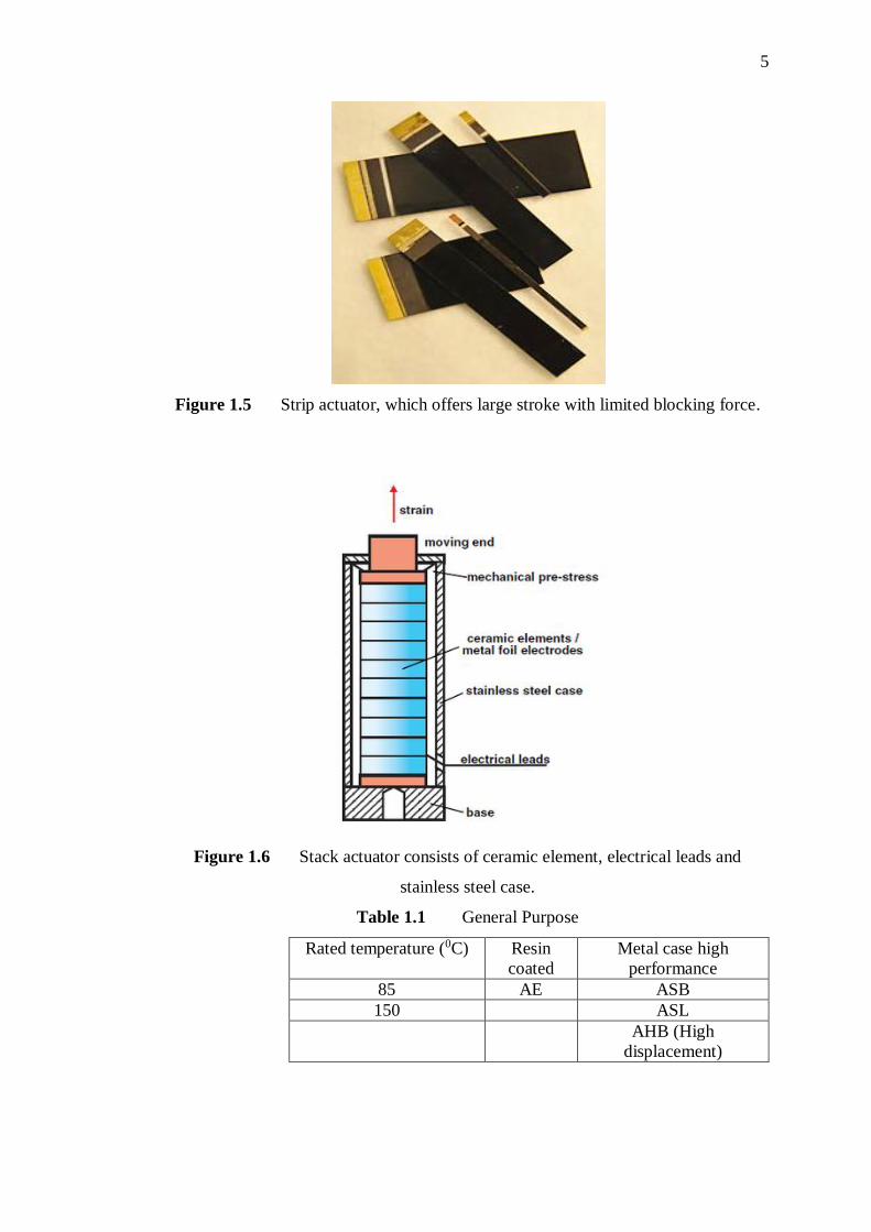
1.4 (a) Sensor uses the principle of piezoelectric effect to
convert applied pressure into electrical signal while (b)
Actuator uses inverse piezoelectric to increase the size of
the piezoelectric material by converting voltage into
displacement. 4
1.5 Strip actuator, which offers large stroke with limited
blocking force. 5
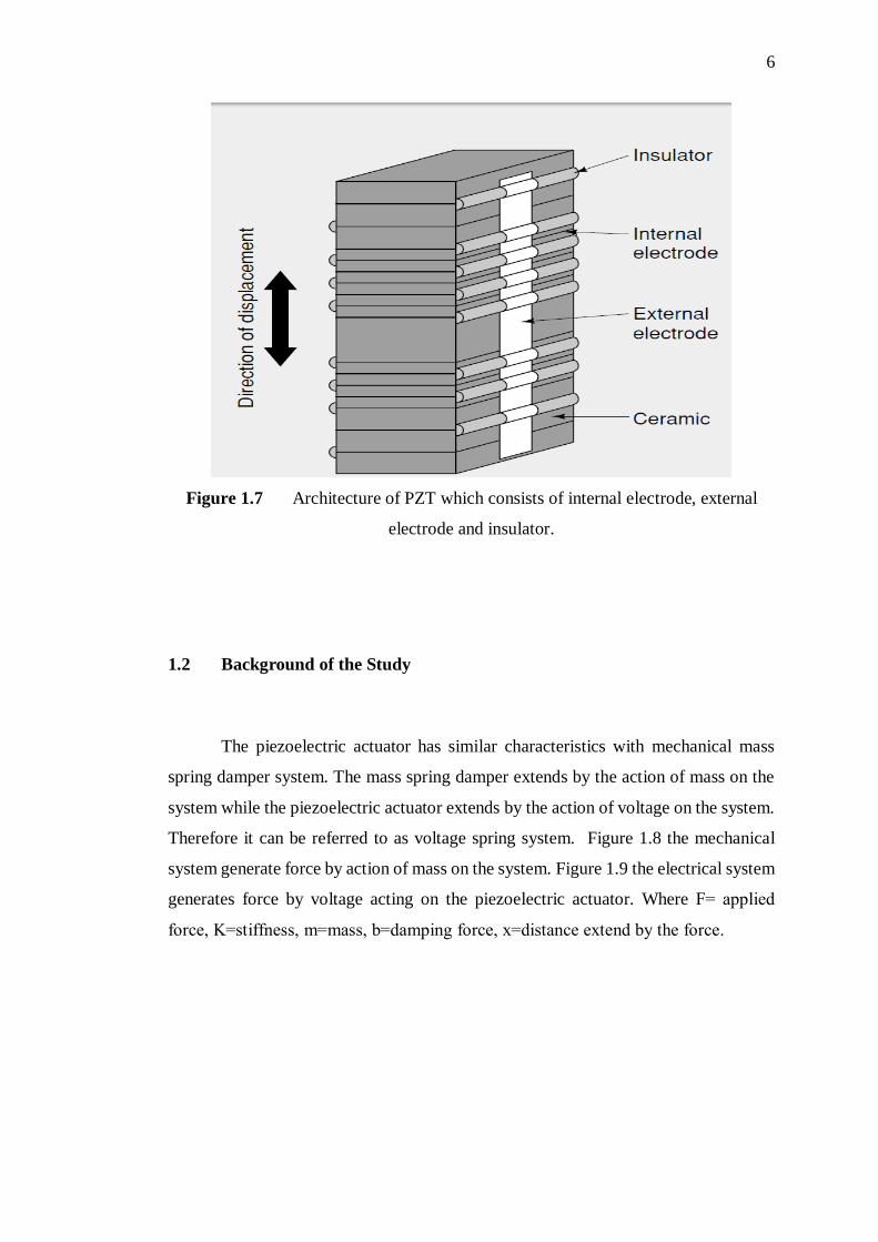
1.6 Stack actuator consists of ceramic element, electrical
leads and stainless steel case. 5
1.7 Architecture of PZT which consists of internal electrode,
external electrode and insulator. 6
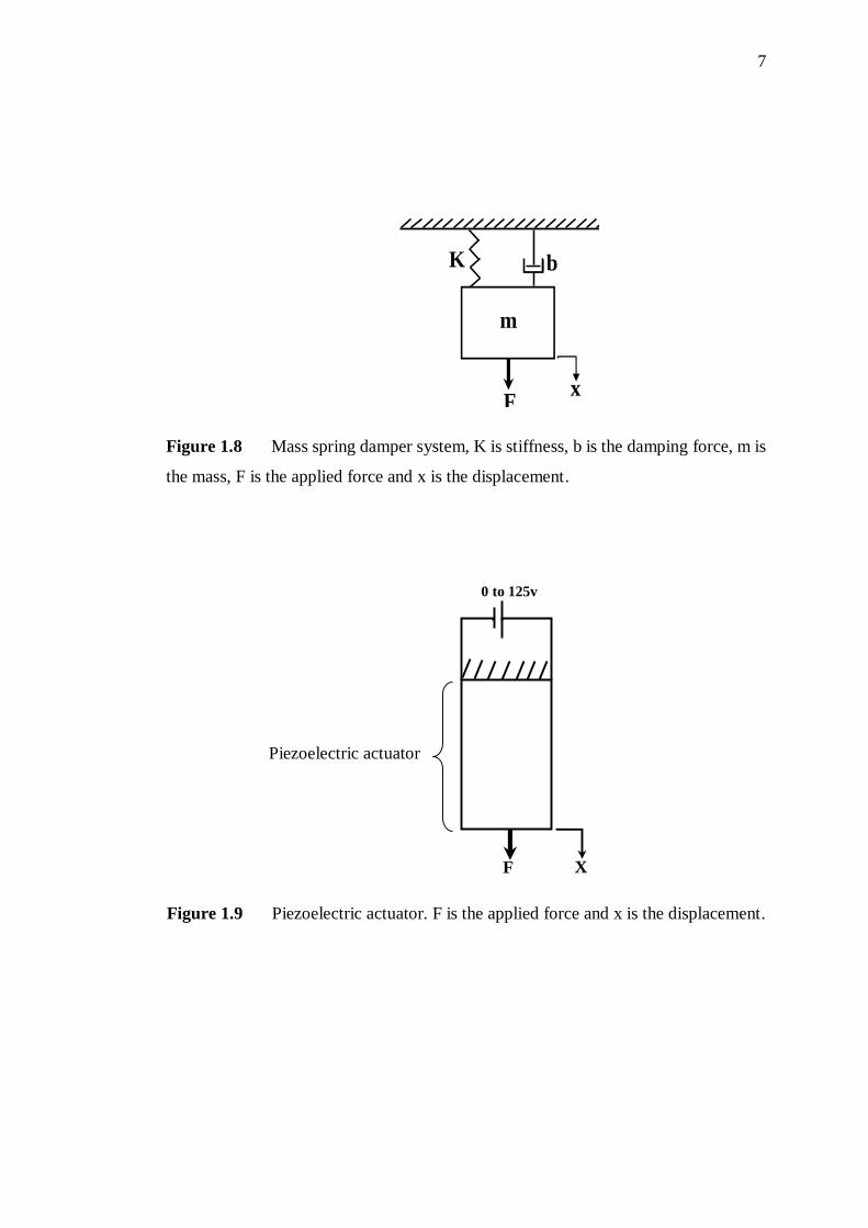
1.8 Mass spring damper system, K is stiffness, b is the
damping force, m is the mass, F is the applied force and
x is the displacement. 7
xiii
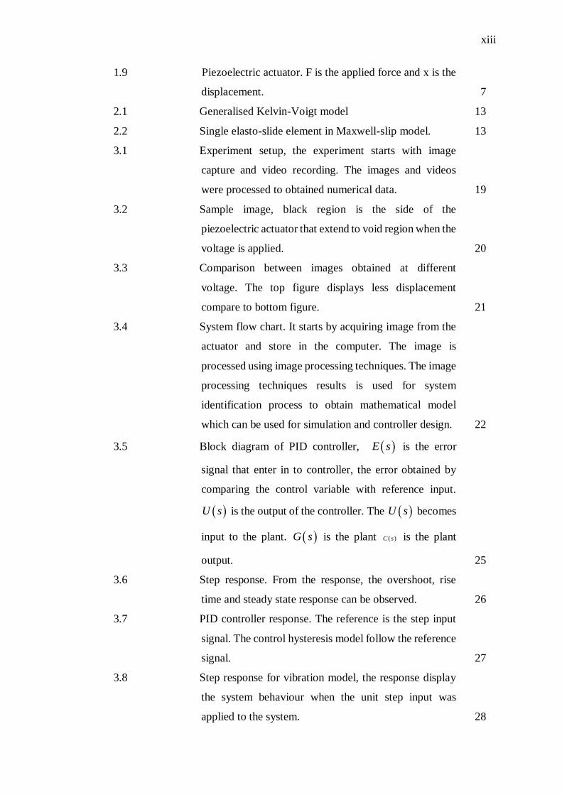
1.9 Piezoelectric actuator. F is the applied force and x is the
displacement. 7
2.1 Generalised Kelvin-Voigt model 13
2.2 Single elasto-slide element in Maxwell-slip model. 13
3.1 Experiment setup, the experiment starts with image
capture and video recording. The images and videos
were processed to obtained numerical data. 19
3.2 Sample image, black region is the side of the
piezoelectric actuator that extend to void region when the
voltage is applied. 20
3.3 Comparison between images obtained at different
voltage. The top figure displays less displacement
compare to bottom figure. 21
3.4 System flow chart. It starts by acquiring image from the
actuator and store in the computer. The image is
processed using image processing techniques. The image
processing techniques results is used for system
identification process to obtain mathematical model
which can be used for simulation and controller design. 22
3.5 Block diagram of PID controller, E s is the error
signal that enter in to controller, the error obtained by
comparing the control variable with reference input.
U s is the output of the controller. The U s becomes
input to the plant. G s is the plant ( )C s is the plant
output. 25
3.6 Step response. From the response, the overshoot, rise
time and steady state response can be observed. 26
3.7 PID controller response. The reference is the step input
signal. The control hysteresis model follow the reference
signal. 27
3.8 Step response for vibration model, the response display
the system behaviour when the unit step input was
applied to the system. 28
xiv
3.9 PID controller response for vibration, reference input
signal was applied to the system which was track system
control vibration model. 28
3.10 Vibration control using pulse generator. 29
4.1 Import data. This is the first window that will appear after
starting the system identification tool box. It give an
option to select time domain or frequency domain data
to perform system identification process. 33
4.2 Selecting starting time and sampling interval. This
window will allow to select the starting time and
sampling interval. 34
4.3 The time domain data was imported and data is ready to
be used for system identification process. 34
4.4 Estimation process. The time domain data is divided into
working data and validation data. First half of the data
will be used for identification process while the second
half will be used for validation. 35
4.5 Input and output signals. y1 (displacement) displays the
output response verses time and input signal. u1
(voltage) displays the staircase input voltage verses time.
From the graph we can see the hysteresis nature of the
actuator 35
4.6 The nonlinear graph shown above is knows as hysteresis.
Hysteresis curve displays two different curves,
ascending loop and descending loop. The ascending loop
occurs when the voltage increase with time while
descending loop occurs when the voltage is reducing
with time. 36
4.7 Step responses of the system, the step response shows the
system is under damped second order system. 37
4.8 Simulation block. This is used to simulate and view the
response of estimated system. 38
xv
4.9 Stair case input voltage (V) verses time, the voltage was
applied from DC power supply in 5 V increment starting
from zero to 125 V and then from 125 V to zero. 39
4.10 Simulation output. The displacement of the actuator
verses time. 39
4.11 Step response for the estimated model. This response
displays the system output when unit step response was
applied to the estimated model. 40
4.12 Output of both actual and simulated models. 41
4.13 Step response of actual and estimated models. From the
response it can be seen that the estimated model has less
overshoot than actual model. 41
4.14 Setup for generating vibration. The figure contains 5
sections. Section 1 shows the computer system which
contains Arduino software. Section 2 displays the
Arduino program transferred from computer system to
microcontroller. Section 3 display the Arduino
microcontroller that generate output voltage for 5000 ms
and delay of 5000 ms and transfer it to UA741. In section
4, the UA741 amplifies the input based on resistance
gain. Section 5 display the oscilloscope which display
the output signal of UA741. Section 6 shows the
vibrating PZT actuator. 43
4.15 Setup for image and video processing. This figure
consists of section 7 to 12. Section 7 displays the
computer system which capture image and video from
the actuator. Section 8 shows image and video
processing using image and video processing software.
Section 9 shows the data obtained from image and video
processing software. Section 10 shows system
identification procedure from Matlab interface. Section
11 display the signal output from system identification
tool. Section 12 display the system model. 44
4.16 UA741 amplifier circuit. 45
xvi
4.17 The system input and output verses time was obtained
when the data from table 3.4 was uploaded in the Matlab
system identification tool box. The input is square wave
form with amplitude that determine by the magnitude of
the applied voltage. The output is a vibration as depicted
in the responses above. 48
4.18 Vibration model step response 49
4.19 Simulation block model. The input part of this block
holds the stair case input voltage. G(s) contains the
transfer function of the estimated vibration model. 50
4.20 Estimated model step response. This response was
obtained from estimated vibration models. 50
4.21 The response curve compare the similarity between
actual and simulation result of vibration model of
piezoelectric actuator. 51
4.22 Block diagram of PID controller. The PID controller2
controls the vibration of vibration estimated model,
while the PID controller1 controls the hysteresis of the
hysteresis estimated model. 54
4.23 Hysteresis control. From the figure, it can be seen how
the PID controller tracks the reference signal. 55
4.24 Vibration control. From the figure, it can be seen that the
controller tracks the unit step reference input. 56
4.25 Vibration control using pulse generator. 57
4.26 Comparison between the system with controller and the
system without controller using step input on hysteresis
model. 58
4.27 Comparison of hysteresis model with PID controller and
the one without controller using staircase input voltage. 59
4.28 Compare of vibration model between the one with
controller and the one without controller using step input
signal. 60
4.29 Comparison between vibration model with controller and
the one without controller. 61
xvii
LIST OF ABBREVATIONS
CARMA - Controlled Autoregressive Moving Average
DC - Direct Current
LR - Inductor Resistor
MVSTDR - Minimum Variance Self-tuning Direct Regulator
MOC - Model Predictive Controller
NARMAX - Nonlinear Autoregressive Moving Average with
Exogenous input
PID - Proportional Integral and Derivative
PZT - Piezoelectric Actuator
xviii
LIST OF APPENDICES
APPENDIX
TITLE PAGE
A Standard Part list 70
B Matlab and arduino programme 71
CHAPTER 1
INTRODUCTION
1.1 Introduction
Piezoelectricity is the electricity resulting from pressure.
It derived from Greek piezo or piezein which mean to squeeze or press. Piezoelectric
actuator is a displacement transducer that converts electrical signals to physical
displacement. Many physical models have been used for modelling piezoelectric
actuators [1]. Piezoelectric materials are made of crystals (e.g. Quartz), ferroelectric
polycrystalline ceramic substances, piezoceramics (e.g. Barium titanate (BaTio3)
and lead zirconate titanate (PZA). All these materials respond to mechanical
force/torque or electrical voltage/charge in a short time; they also can couple
electrical and mechanical properties to each other. These materials are employed in
different structures such as piezoceramic thin flat patches, piezoelectric stacks,
piezoelectric tubes and piezoelectric strips embedded into a polymer matrix [2]. The
piezoelectric actuator is over-damped second order system. The displacement of the
actuator is proportional to the voltage applied. The frequency bandwidth is
proportional to stiffness and inverse proportional to damping constant and mass [3].
There are two types of piezoelectric actuator namely strip actuator and stack actuator.
Resin coated type of stack actuator offer low displacement than metal case type.
Some of the applications of piezoelectric actuator are as follows. It is used in disk
drived head positioning system with reliable performance [4]. Sizeable displacement
and reasonable force are provided by piezoelectricmicroactuator for efficient
mechanical microactuation mechanism which offers application in microoptics,
2
micro relays and micro grippers [5]. It is used as pump actuators in lab on chip in
microfluidic system as well as in inkjet printed actuators that have applications on
lab on chip technology [6],[7]. Vibration energy can be harvested from piezoelectric
devices with harvesting efficiency of more than two fold as compared to quasi-
resistive impedance matching. It is possible to control vibration and harvest energy
in piezoelectric actuator [8],[9]. It is used in cell wall cutting [10]. Three phenomena
are observed in piezoelectric actuators behaviour; [2].
i. Hysteresis: is regarded as having different output values of a system with an
identical input value.
ii. Creep: The decrease of the amplitude of piezoelectric actuator displacements
by time while the input voltage is maintained is called creep which can cause error in
long operations.
iii. Structural vibration: Piezoelectric actuators vibration is a function of
mechanical properties of the actuator such as mass, stiffness and damping. Structural
vibration is more significant close to resonance frequencies.
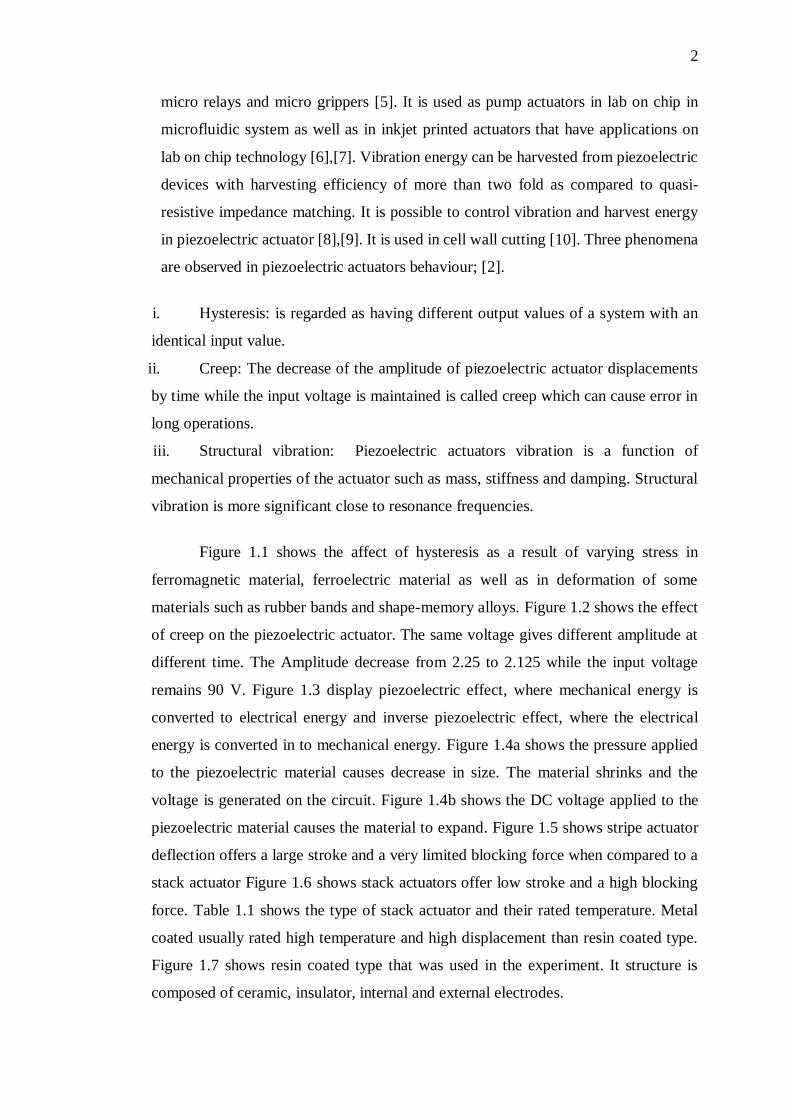
Figure 1.1 shows the affect of hysteresis as a result of varying stress in
ferromagnetic material, ferroelectric material as well as in deformation of some
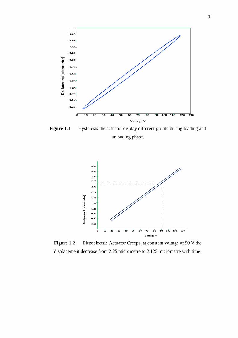
materials such as rubber bands and shape-memory alloys. Figure 1.2 shows the effect
of creep on the piezoelectric actuator. The same voltage gives different amplitude at
different time. The Amplitude decrease from 2.25 to 2.125 while the input voltage
remains 90 V. Figure 1.3 display piezoelectric effect, where mechanical energy is
converted to electrical energy and inverse piezoelectric effect, where the electrical
energy is converted in to mechanical energy. Figure 1.4a shows the pressure applied
to the piezoelectric material causes decrease in size. The material shrinks and the
voltage is generated on the circuit. Figure 1.4b shows the DC voltage applied to the
piezoelectric material causes the material to expand. Figure 1.5 shows stripe actuator
deflection offers a large stroke and a very limited blocking force when compared to a
stack actuator Figure 1.6 shows stack actuators offer low stroke and a high blocking
force. Table 1.1 shows the type of stack actuator and their rated temperature. Metal
coated usually rated high temperature and high displacement than resin coated type.
Figure 1.7 shows resin coated type that was used in the experiment. It structure is
composed of ceramic, insulator, internal and external electrodes.
3
Figure 1.1 Hysteresis the actuator display different profile during loading and
unloading phase.
Figure 1.2 Piezoelectric Actuator Creeps, at constant voltage of 90 V the
displacement decrease from 2.25 micrometre to 2.125 micrometre with time.
Piezoelectric Actuator Displacement (µm) verses Voltage (V)
3.25
3.00
2.75
2.50
2.25
2.00
1.75
1.50
1.25
1.00
0.75
0.50
0.25
0 10 20 30 40 50 60 70 80 90 100 110 120 130
Voltage V
Dis
plac
emen
t (m
icro
met
er)
Time
3.25
3.00
2.75
2.50
2.25
2.00
1.75
1.50
1.25
1.00
0.75
0.50
0.25
0 10 20 30 40 50 60 70 80 90 100 110 120 130
Voltage V
Piezoelectric Actuator Creep
Disp
lace
men
t (m
icrom
eter
)
4
Figure 1.3 Piezoelectric properties. Piezoelectric effect converts mechanical
energy is to electrical energy whereas inverse piezoelectric effect converts electrical
energy to mechanical energy.
Figure 1.4 (a) Sensor uses the principle of piezoelectric effect to convert applied
pressure into electrical signal while (b) Actuator uses inverse piezoelectric to increase
the size of the piezoelectric material by converting voltage into displacement.
(a) (b)
Pressure
Pressure
5
Figure 1.5 Strip actuator, which offers large stroke with limited blocking force.
Figure 1.6 Stack actuator consists of ceramic element, electrical leads and
stainless steel case.
Table 1.1 General Purpose
Rated temperature (0C) Resin
coated
Metal case high
performance
85 AE ASB
150 ASL
AHB (High
displacement)
6
Figure 1.7 Architecture of PZT which consists of internal electrode, external
electrode and insulator.
1.2 Background of the Study
The piezoelectric actuator has similar characteristics with mechanical mass
spring damper system. The mass spring damper extends by the action of mass on the
system while the piezoelectric actuator extends by the action of voltage on the system.
Therefore it can be referred to as voltage spring system. Figure 1.8 the mechanical
system generate force by action of mass on the system. Figure 1.9 the electrical system
generates force by voltage acting on the piezoelectric actuator. Where F= applied
force, K=stiffness, m=mass, b=damping force, x=distance extend by the force.
7
Figure 1.8 Mass spring damper system, K is stiffness, b is the damping force, m is
the mass, F is the applied force and x is the displacement.
Figure 1.9 Piezoelectric actuator. F is the applied force and x is the displacement.
0 to 125v
F X
Piezoelectric actuator
b K
x F
m
8
1.3 Problem Statement
The main problems of piezoelectric actuator are hysteresis, creep, structural
vibration and associated nonlinearities. There is structural vibration which is
associated with natural frequency. The static (non-dynamic) piezoelectric actuator
models were not represented by single transfer function. The modelling of dynamic
(vibrating) piezoelectric actuator was not previously considered. This project will
emphasise on modelling piezoelectric actuator. Generating vibration at desire
frequency and modelling of vibrating piezoelectric actuator. The project will also
highlight controller design to control both hysteresis and vibration of the piezoelectric
actuator.
1.4 Objectives
The main objective of this project is to control the piezoelectric actuator for
accurately producing a vibration actuation. The above main objective can be divided
into four sub-objectives as outline below:
i. To develop a model of both static (non-vibrating) and dynamic (vibrating)
piezoelectric actuator using system identification technique.
ii. To implement the PID controller for hysteresis minimization using simulation.
iii. To implement the PID controller for vibration control using simulation.
9
1.5 Scopes of the Study
This project focused on modeling of piezoelectric actuator and modeling of
vibrating piezoelectric actuator using system identification technique. The first PID
controller was designed based on verified model to minimize the hysteresis. The
second PID controller was designed to control vibration actuation. Due to the
difficulties in dealing with nonlinear system of the piezoelectric actuator, the linear
system model was used for analysis. The performances of the PID controllers were
realized through simulation.
1.6 Significances and Original Contributions of the Study
The main contribution of this project is provides a means of precise control and
manipulation of piezoelectric actuator to be used for micro and Nano-technology
applications. The vibration of the actuator can also be used for precise cutting at micro
level.
1.7 Project Outline
This project report is organized in four chapters. Chapter one gives an overview
of the system, objectives and scope of the project and also gives introduction regarding
the problem to be solved. Chapter two reviews some previous research and literatures

10
related to this project. Chapter three provides steps of the methodology and description
of each procedure to be followed in order to solve the problem at in view. Chapter four
presents discussion of the results. Chapter five presents conclusion on the
achievements of the project and also set forth some recommendations for further future
works.
66
REFERENCES
[1] N. Miri, M. Mohammad Zaheri, L. Chen, S. Grainger, and M. Bazghaleh,
“Physics-based modelling of a piezoelectric actuator using genetic algorithm,”
in IEEE Symposium on Industrial Electronics & Applications, 2013, pp. 16–20.
[2] N. Miri and M. Mohammad Zaheri, “A comparative study of different physics-
based approaches to modelling of piezoelectric actuators,” in 2013 IEEE/ASME
International Conference on Advanced Intelligent Mechatronics, 2013, pp.
1211–1216.
[3] P. Li, J. Fu, Y. Wang, Z. Xing, and M. Yu, “Dynamic Model and Parameters
Identification of Piezoelectric Stack Actuators,” in 26th Chinese Control and
Decision Conference (CCDC), pp. 1918–1923, 2014.
[4] Z. He, H. T. Loh, M. Xie, S. Member, G. Guo, and N. E, “A Reliability Model
for Piezoelectric Actuators,” 7th Int. Power Eng. Conf., pp. 1–6, 2005.
[5] T. Freyhold and U. Wallrabe, “Development of Miniaturized Piezoelectric
Actuators for Optical Applications Realized Using LIGA Technology,” IEEE
Jounal Microelectromechanical Syst., vol. 8, no. 3, pp. 258–263, 1999.
[6] O. Pabst, J. Perelaer, E. Beckert, U. S. Schubert, R. Eberhardt, and A.
Tünnermann, “All inkjet-printed piezoelectric polymer actuators :
Characterization and applications for micropumps in lab-on-a-chip systems,”
Org. Electron., vol. 14, no. 12, pp. 3423–3429, 2013.
[7] O. Pabst, S. Hölzer, E. Beckert, J. Perelaer, U. S. Schubert, R. Eberhardt, and
A. Tünnermann, “Inkjet printed micropump actuator based on piezoelectric
polymers : Device performance and morphology studies,” Org. Electron., vol.
15, no. 11, pp. 3306–3315, 2014.
[8] I. S. Method, “A Self-Powered Piezoelectric Vibration Control System With
Switch Precharged,” IEEE Trans. Mechatronics, vol. 20, no. 2, pp. 773–781,
2015.
67
[9] J. Sankman and D. Ma, “A 12- μ W to 1 . 1-mW AIM Piezoelectric Energy
Harvester for Time-Varying Vibrations With 450-nA I Q,” IEEE Trans. Power
Electron., vol. 30, no. 2, pp. 632–643, 2015.
[10] M. Habibur Rahman, Abdul Hafis mat Sulaiman, Ridzuan Ahmad, “Finite
Element Analysis of Single Cell Wall Cutting by Piezoelectric-Actuated
Vibrating Rigid Nanoneedle,” IEEE Trans. Nanotechnol., vol. 12, no. 6, pp.
1158–1165, 2013.
[11] H. Jiang, H. Ji, J. Qiu, and Y. Chen, “A modified Prandtl-Ishlinskii model for
modeling asymmetric hysteresis of piezoelectric actuators.,” IEEE Trans.
Ultrason. Ferroelectr. Freq. Control, vol. 57, no. 5, pp. 1200–1210, 2010.
[12] Z. Wei, B. L. Xiang, and R. X. Ting, “Online parameter identification of the
asymmetrical Bouc–Wen model for piezoelectric actuators,” Precis. Eng., vol.
38, no. 4, pp. 921–927, 2014.
[13] I. M. Bahadur and J. K. Mills, “A new model of hysteresis in piezoelectric
actuators,” in IEEE International Conference on Mechatronics and Automation,
vol. 1, pp. 789–794, 2011.
[14] A. K. Kottari, A. E. Charalampakis, and V. K. Koumousis, “A consistent
degrading Bouc–Wen model,” Eng. Struct., vol. 60, pp. 235–240, 2014.
[15] F. Ikhouane, V. Mañosa, and J. Rodellar, “Dynamic properties of the hysteretic
Bouc-Wen model,” Syst. Control Lett., vol. 56, no. 3, pp. 197–205, 2007.
[16] C. Hui, T. Yonghong, Z. Xingpeng, D. Ruili, and Z. Yahong, “Identification of
Dynamic Hysteresis Based on Duhem Model,” in Fourth International
Conference on Intelligent Computation Technology and Automation, pp. 810–
814, 2011.
[17] R. Ouyang and B. Jayawardhana, “Absolute stability analysis of linear systems
with Duhem hysteresis operator,” Automatica, vol. 50, no. 7, pp. 1860–1866,
2014.
[18] Y. Bernard, E. Mendes, and F. Bouillault, “Dynamic hysteresis modeling based
on Preisach model,” IEEE Trans. Magn., vol. 38, no. 2, pp. 885–888, 2002.
[19] A. Matsubara, M. Maeda, and I. Yamaji, “Vibration suppression of boring bar
by piezoelectric actuators and LR circuit,” CIRP Ann. - Manuf. Technol., vol.
63, no. 1, pp. 373–376, 2014.
[20] T. Zhang, H. G. Li, and G. P. Cai, “Hysteresis identification and adaptive
vibration control for a smart cantilever beam by a piezoelectric actuator,”
Sensors Actuators A Phys., vol. 203, pp. 168–175, 2013.
68
[21] C. Abis, F. Unal, and A. Mugan, “Active vibration control with piezoelectric
actuator on a lathe machine with a gain controller,” in IEEE International
Conference on Mechatronics, pp. 19–22, 2011.
[22] C.-Y. S. and M. O. Jian Wang, “Theoretic Modeling and Adaptive Control for
Two Degree-of-Freedom Piezo-Electric Actuated Chatter Suppression
System,” in 42nd IEEE Conference on Decision and Control, pp. 4315–4320,
2003.
[23] H. Numasato and M. Tomizuka, “Settling control and performance of a dual-
actuator system for hard disk drives,” IEEE/ASME Trans. Mechatronics, vol. 8,
no. 4, pp. 431–438, 2003.
[24] W. M. Chen and T. S. Liu, “Modeling and experimental validation of new two
degree-of-freedom piezoelectric actuators,” Mechatronics, vol. 23, no. 8, pp.
1163–1170, 2013.
[25] F. M. and A. S. M. khaled Joujou, “Experimental fuzzy logic active vibration
control,” in 5th International Symposium on Mechatronics and its Applications
(ISMA08), pp. 6–12, 2008.
[26] Z. Kai, D. Xinghui, and W. Dongsheng, “Intelligent vibration control of piezo-
electric truss structure using GA-based fuzzy neural network,” 8th World
Congr. Intell. Control Autom., pp. 5136–5139, 2010.
[27] W. Li and X. Chen, “Compensation of hysteresis in piezoelectric actuators
without dynamics modeling,” Sensors Actuators A Phys., vol. 199, pp. 89–97,
2013.
[28] F. Heidary and M. Reza Eslami, “Piezo-control of forced vibrations of a
thermoelastic composite plate,” Compos. Struct., vol. 74, no. 1, pp. 99–105,
2006.
[29] Y. Cao, L. Cheng, X. B. Chen, and J. Y. Peng, “An Inversion-Based Model
Predictive Control With an Integral-of-Error State Variable for Piezoelectric
Actuators,” IEEE/ASME Trans. Mechatronics, vol. 18, no. 3, pp. 895–904,
2013.
[30] K. Ogata, Modern Control Engineering, 5th ed. New Jersey, USA: Pearson
Education Incorporation, 2012.
Recommended