Balkans and Regional Energy Market Partnership Program: Regional Dynamic Model Construction Report
MAIN DOCUMENT Southeast Europe Cooperation Initiative Transmission System Planning Project (SECI)
Cooperative Agreement EEE-A-02-00054-00
Thursday, January 31, 2013
This report made possible by the support of the American people through the United States Agency for International Development (USAID). The contents are the responsibility of the United States Energy Association and do not necessarily reflect the views of USAID or the United States Government.
Balkans and Regional Energy Market Partnership Program
Regional Dynamic Model Construction Report
Southeast Europe Cooperation Initiative Transmission System Planning Project (SECI)
Prepared for:
United States Agency for International Development and United States Energy Association
Cooperative Agreement EEE-A-02-00054-00
Authors:
Djordje Dobrijevic, Project Manager, Electricity Coordinating Center (EKC)
Nemanja Krajisnik, Team Member, Electricity Coordinating Center (EKC)
Milos Stojkovic, Team Member, Electricity Coordinating Center (EKC)
Predrag Miksa, Team Member, Electricity Coordinating Center (EKC)
United States Energy Association 1300 Pennsylvania Avenue, NW
Suite 550, Mailbox 142 Washington, DC 20004 +1 202 312-1230 (USA)
This report is made possible by the support of the American people through the United States Agency for International Development (USAID). The contents are the responsibility of the United States Energy Association and do not necessarily reflect the views of USAID or the United States Government.

ACKNOWLEDGMENTS
Authors of this Study would like to thank all SECI members who took time to participate in project preparation and USAID for financial support not only for this Study, but the Project as a whole. Regional transmission planning group under the infrastructure of SECI has been established and financially supported by USAID since 2001.

DISCLAIMER
This study (Regional Dynamic Model Construction) is financed by the United States Agency for International Development and the American people. The United States of America recognizes the Republic of Kosovo. The study makes reference to Kosovo under the title "Kosovo*" accompanied by the footnote "This designation is without prejudice to positions on status, and is in line with UNSCR 1244 and ICJ Advisory opinion on the Kosovo declaration of independence."
The authors used this term in accordance EU moderated Agreement between Belgrade - Prishtina from February 2012 and it is consistent with the terminology initially adopted by the Southeast Europe Cooperation Initiative (SECI) Transmission System Planning Project. The reference to Kosovo has no any impact on the study results.
i
Contents
ABBREVIATIONS .................................................................................................................................................................. ii General .............................................................................................................................................................................. ii Transmission ...................................................................................................................................................................... ii Generation ........................................................................................................................................................................ iii Countries ........................................................................................................................................................................... iii
EXECUTIVE SUMMARY ...................................................................................................................................................... 1 1 INTRODUCTION ........................................................................................................................................................ 1.1 2 METHODOLOGY ....................................................................................................................................................... 2.1
2.1 Prerequisites and Assumptions ........................................................................................................................... 2.1 2.1.1 Transient stability assessment ................................................................................................................... 2.1 2.1.2 Mid-term stability assessment .................................................................................................................... 2.2
2.2 Dynamic Models construction and validation procedure ...................................................................................... 2.3 2.2.1 Construction of models for dynamic analyses ............................................................................................ 2.4 2.2.2 Verification of model for dynamic analyses ................................................................................................ 2.4
3 CONSTRUCTION OF DYNAMIC MODEL ................................................................................................................. 3.1 4 RESULTS OF PRELIMINARY TESTING ................................................................................................................... 4.1 5 FINDINGS AND NEXT STEPS .................................................................................................................................. 5.1 6 REFERENCES ........................................................................................................................................................... 6.1
ii
AABBBBRREEVVIIAATTIIOONNSS
GGeenneerraall
TSO – Transmission System Operator TEN-E – Trans-European Energy Networks
CIGRÉ – International Council on Large Electric Systems UCTE – Union for the Coordination of Transmission of Electricity
ENTSO/E – European Network of Transmission System Operators for Electricity (former UCTE)
ACER – Agency for the Cooperation of Energy Regulators NRA – National Regulatory Authority or Agency
IEM – Internal Energy Market REM – Regional Energy Market
LOLE – Loss of Load Expectation SAF – System Adequacy Forecast
SoS – Security of Supply
VOLL – Value of Lost Load ETS – Emission Trading System
EWIS – European Wind Integration Study CENTREL – Association of TSOs of Czech Republic, Hungary, Poland and Slovakia
SEE – South East Europe
SECI – South East European Cooperation Initiative BSTP – Black Sea Transmission Project
FIT – feed-in tariff LF – Load flow
OPF – Optimal power flow
FGC, UNEG – Federal Grid Company, Unified National Electric Grid IPS/UPS – Interregional Power System/Unified Power System
TTrraannssmmiissssiioonn
AC – Alternating Current DC – Direct Current
HV – High Voltage MV – Medium Voltage
LV – Low Voltage HVAC – High Voltage AC
HVDC – High Voltage DC
EMF – Electromagnetic Field ED – Electricity Distribution
SS – Substation OHL – Overhead Lines
UC – underground cable
SC – submarine cable TR – Transformer
OLTC – On Load Tap Changer PST – Phase Shifting Transformer
SCR – Short Circuit Ratio ESCR – Effective Short Circuit Ratio
CCT – Critical Clearing Time
LCC – Line Commutated Converter FACTS – Flexible AC Transmission System
VSC – Voltage Source Converter STATCOM – Static Synchronous Compensator
iii
NTC – Net Transfer Capacity
TTC – Total Transfer Capacity
RC – Remaining Capacity RAC – Reliable Available Capacity
GGeenneerraattiioonn
HPP – Hydro Power Plant PHPP – Pumping Hydro Power Plant
TPP – Thermal Power Plant NPP – Nuclear Power Plant
CCGT – Combined cycle gas turbine
CCS – Carbon Capture and Storage CHP – Combined Heat and Power Generation
RES – Renewable Energy Sources NGC – Net Generation Capacity
VAR – Volt-Ampere-Reactive, reactive power
BTU – Brithish Thermal Unit = 1055J = 0.293Wh = 252cal, mBTU = 1000000BTU tcm – thousand cubic meter 1000m3
RGC – Regional Generation Company TGC – Territorial Generation Company
WGC – Wholesale Generation Company
CCoouunnttrriieess
ISO Country Car
Austria AT AUT A Albania AL ALB AL
Bosnia and Herzegovina BA BIH BiH
Bulgaria BG BUL BG Croatia HR CRO CRO
Germany DE GER D Greece GR GRE GR
Hungary HU HUN HU
Italy IT ITA I Macedonia MK FYRM MAK
Montenegro ME MNE MNE Romania RO ROM ROM
Serbia RS SRB SRB Slovenia SI SLO SLO
Switzerland CH SUI CH
Turkey TR TUR TUR Ukraine UA UKR UKR

1
EEXXEECCUUTTIIVVEE SSUUMMMMAARRYY
The SECI was established by the United States Agency for International Development, the United States Energy Association and the transmission system operators of the South Eastern European region in 2001 to
build institutional capacity to develop and analyze the region’s first common transmission planning model.
Members of the project working group represent the transmission system operators (TSO) of Albania, Bulgaria, Bosnia and Herzegovina, Croatia, Macedonia, Montenegro, Romania and Serbia. Currently,
developed regional transmission system models include also models of Austria, Greece, Hungary, Italy, Slovenia and Turkey.
The Power System Simulator for Engineers (PSS/E) software was selected as the common planning software
platform for the project. The project supplied each TSO with the software and has provided ongoing training
in its use and application to build capacity in the region to construct national and regional models of the South Eastern European high voltage electric power transmission network.
The objective of this Report is to review all necessary technical data for all SECI countries and the region as a
whole used in regional transmission planning project with a focus on dynamic regional simulation model.
Based on data collected and data base constructed, each project participant prepared dynamic model of their
system and provided it to model integrator to make regional dynamic model.
Obligations of model integrator concerning this item are as follows:
Review all collected data to check that they conform to the agreed numbering systems for areas, zones and busses, and questionnaire format
Provide consultancy for isolated model building to the project participants Review and test operation of respective isolated models for each system
Merge all model data in order to form one model Test the operation of the regional model
Prepare a Regional model report that consist of summary data for regional model, characteristics of
the regional model and dynamic data database Distribute regional model to all participants
Regional Dynamic model and data base is prepared based on the most recent version of load flow models for
following regimes:
Winter Peak Summer Peak
Summer Off-Peak where each of these regime is modeled for following target years:
2015 2020
The developed dynamic Regional model consist of following parts: Load flow model in PSS/E format (*.sav file)
Dynamic model in PSS/E format (*.dyr file) that corresponds to Load flow file
Dynamic model is developed in the most recent version of the PSS/E (currently, the version is 33). USAID and
USEA provided full PSS/E program support to all project participants in order to accomplish model building. EKC experts have built adequate dynamic models for Russian and Ukrainian build excitation systems that can
and will be used by all participating parties in project.
Complete country models which are incorporated into the SECI dynamic model are developed for Albania,
Austria, Bosnia & Herzegovina, Bulgaria, Croatia, Hungary, Romania, Slovenia, Serbia and Kosovo*. The influence of external system is included by modeling of equivalent generators on border of system of interest.
Modeling of power plants for Austria and Hungary was performed in concordance with the load flow model of these countries where there are only power plants connected directly to 400 kV and 220 kV voltage level

2
without step-up transformers. Dynamic model of Greece is made in almost complete form. All major power
plants were modeled except for the few smaller ones for which there was no information about the type.
These unknown small power plants were converted into negative load. Due to the fact that the full dynamic model of Italy is not available at the moment, only the northern part of Italy along with the border towards
Austria and Slovenia was modeled. The rest of Italy was represented by equivalent generators. These equivalent generators should represent dynamic response of Italy as well as of one part of ENTSO-E
interconnection. Similar approach was made regarding Turkey, where there was a suitable topology of the
power system which enabled the modeling of European part only (full dynamic model of Turkish power system is not available). The Asian part of Turkey has been represented by equivalent generators. Along the
border of SECI model (load flow cases) equivalent generators were put in the dynamic model to represent the connection of SECI countries to the rest of ENTSO-E interconnection.
Constructed dynamic model has been delivered in electronic form in PSS/E format. Load flow models of all six regimes are in binary format (*.sav files) and dynamic model is in format of ASCII text file (*.dyr file). The
dynamic model in ASCII format (*.dyr file) is common for all six load flow models.
List of generators included in dynamic model, with all data included in dynamic model is given in Appendix C.
These data in Appendix C are per country/TSO.
The objective of this study was to develop dynamic model of the SECI region. All the activities in this process can be summoned into following findings:
• Regional dynamic model corresponding to the latest regional SECI load flow model was developed for
target years 2015 and 2020. • The model is consisted of complete dynamic models per country for detailed country models which
are incorporated into the SECI dynamic model are developed for Albania, Austria, Bosnia & Herzegovina, Bulgaria, Croatia, Hungary, Romania, Slovenia, Serbia and Kosovo*.
• Dynamic model of Turkey, was included into regional model, for European part only, partly due to the
suitable topology of the power system and mainly due to the fact that full dynamic model of Turkish power system is not available.
• Almost complete dynamic model of Greece was made, where all major power plants were modeled, except for the few smaller ones for which there was no information about the type. These unknown
small power plants were converted into negative load. • Dynamic equivalents were used to represent borders of Slovenia, Austria, Hungary and Romania to
model the interconnection with ENTSO-E and Ukraine.
• Preliminary simulations of standard type disturbances (three phase fault on a tie-lines) were performed in order to analyze the responsiveness of the dynamic model and the results have proven
to be acceptable at this stage
Due to the fact that there are still dynamic data missing for several key countries in the region and SECI
project, the development of dynamic model at this stage should be considered as a “work in progress“. After the completion of the dynamic model at this stage, further activities that are imposing themselves include:
• Fine tuning of dynamic parameters for particular plant controllers; • Special attention to the modeling of “Russian school“ controller which are still quite present in
countries of the region;
• Selection of characteristic critical disturbances in the region for further dynamic analyses; • Investigation of actual and historical events that had occurred and their simulation in order to achieve
verification of the developed models.
This study is divided into four parts. The first part is this (main) document, which consist of six chapters. Short introduction is shown in Chapter 1 and Chapter 2 presents methodological approach taken by the
working group and group consultants in building this report. Description of process of dynamic model
construction, which includes the most important issues for regional model construction, as main characteristics of dynamic regional model, is given in Chapter 3 and results of preliminary tests are shown in
Chapter 4. Chapter 5 presents main Findings and Conclusions of this phase of SECI Project and proposes further steps in the model development. Finally, Chapter 6 gives list of the most important literature with
theoretical base for power system dynamics. Appendix A gives short description of PSS/E software which
was used for creation of the dynamic model, while Appendix B presents references for this report on country by country basis. Finally, Appendix C gives review and data of dynamic model on country by country basis

1.1
11 IINNTTRROODDUUCCTTIIOONN
The SECI was established by the United States Agency for International Development, the United States Energy Association and the transmission system operators of the South Eastern European region in 2001 to
build institutional capacity to develop and analyze the region’s first common transmission planning model.
Members of the project working group represent the transmission system operators (TSO) of Albania, Bulgaria, Bosnia and Herzegovina, Croatia, Macedonia, Montenegro, Romania and Serbia.
The Power System Simulator for Engineers (PSS/E) software was selected as the common planning software
platform for the project. The project supplied each TSO with the software and has provided ongoing training in its use and application to build capacity in the region to construct national and regional models of the South
Eastern European high voltage electric power transmission network.
Currently, developed regional transmission system models include also models of Austria, Greece, Hunary,
Italy, Slovenia and Turkey. Figure 1.1 shows transmission network in area of SECI members, with the most important reinforcements included in mid-term planning horizon.
The objective of this Report is to review all necessary technical data for all SECI countries and the region as a whole used in regional transmission planning project with a focus on dynamic regional simulation model.
Figure 1.1: SECI region – New important lines to be commissioned in mid-term period
This study is divided into four parts. The first part in the this (main) document, which consist of six chapters.
Short introduction is shown in Chapter 1 and Chapter 2 presents methodological approach taken by the

1.2
working group and group consultants in building this report. Description of process of dynamic model
construction, which includes the most important issues for regional model construction, as main
characteristics of dynamic regional model, is given in Chapter 3 and results of preliminary tests are shown in Chapter 4. Chapter 5 presents main Findings and Conclusions of this phase of SECI Project and propose
further steps in the model development. Finally, Chapter 6 gives list of the most important literature with theoretical base for power system dynamics.
Appendix A gives short description of PSS/E softwer which was used for creation of the dynamic model,
while Appendix B presents references for this report on country by country basis. Finally, Appendix C gives review and data of dynamic model on country by country basis
2.1
22 MMEETTHHOODDOOLLOOGGYY
In the previous phases of the project the 2010 static and dynamic model developed by the TSOs revealed certain system deficiencies and weak points. Also, the whole region has intencive development of renewable
sources of energy (especially wind power), so to further analyze the capacity of the regional network to
support enhanced trade an exchange of electricity while maintaining security and reliability, and to take into consideration economical factors too, adequate regional dynamic model is necessary.
22..11 PPrreerreeqquuiissiitteess aanndd AAssssuummppttiioonnss
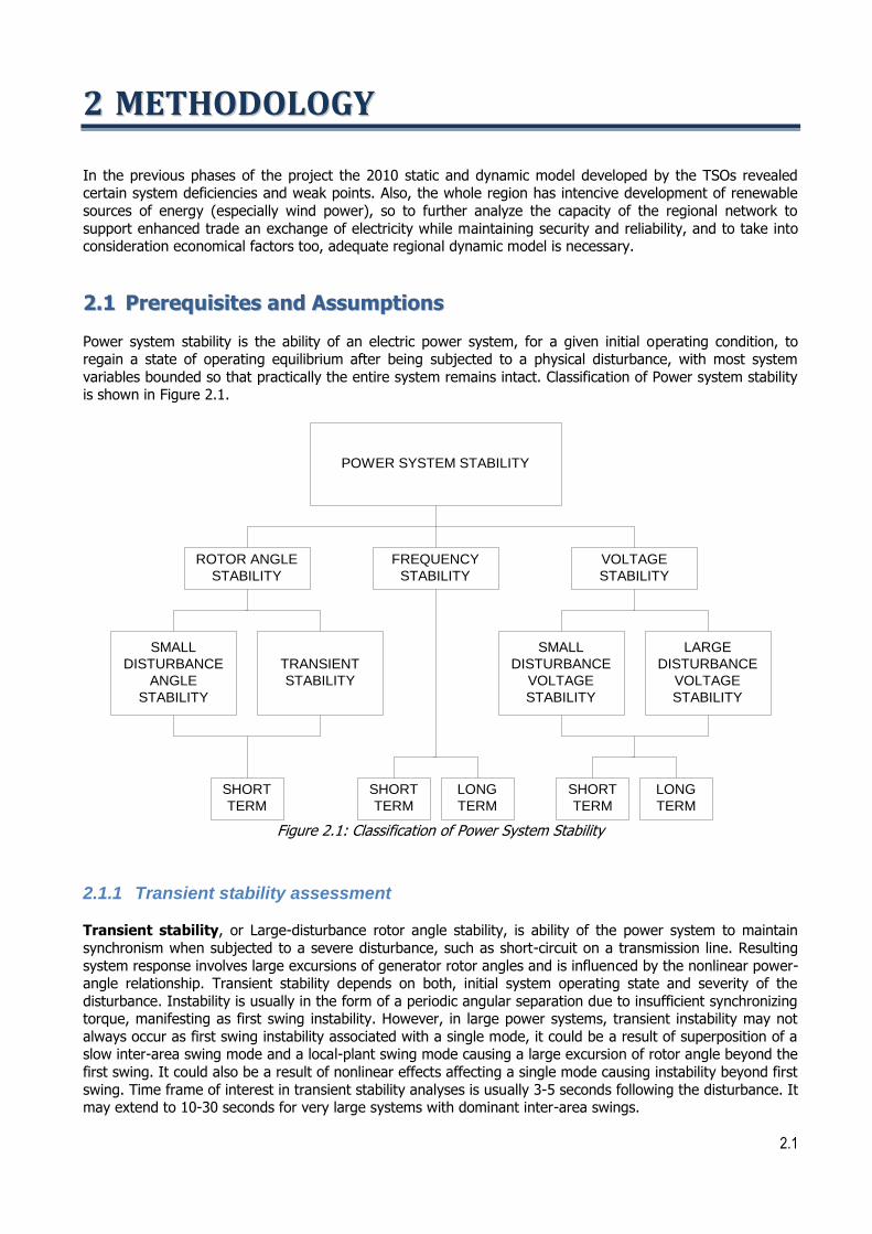
Power system stability is the ability of an electric power system, for a given initial operating condition, to regain a state of operating equilibrium after being subjected to a physical disturbance, with most system
variables bounded so that practically the entire system remains intact. Classification of Power system stability is shown in Figure 2.1.
POWER SYSTEM STABILITY
VOLTAGE
STABILITY
LARGE
DISTURBANCE
VOLTAGE
STABILITY
SMALL
DISTURBANCE
VOLTAGE
STABILITY
SHORT
TERM
LONG
TERM
FREQUENCY
STABILITY
SHORT
TERM
LONG
TERM
ROTOR ANGLE
STABILITY
SMALL
DISTURBANCE
ANGLE
STABILITY
TRANSIENT
STABILITY
SHORT
TERM
Figure 2.1: Classification of Power System Stability
2.1.1 Transient stability assessment
Transient stability, or Large-disturbance rotor angle stability, is ability of the power system to maintain
synchronism when subjected to a severe disturbance, such as short-circuit on a transmission line. Resulting
system response involves large excursions of generator rotor angles and is influenced by the nonlinear power-angle relationship. Transient stability depends on both, initial system operating state and severity of the
disturbance. Instability is usually in the form of a periodic angular separation due to insufficient synchronizing torque, manifesting as first swing instability. However, in large power systems, transient instability may not
always occur as first swing instability associated with a single mode, it could be a result of superposition of a slow inter-area swing mode and a local-plant swing mode causing a large excursion of rotor angle beyond the
first swing. It could also be a result of nonlinear effects affecting a single mode causing instability beyond first
swing. Time frame of interest in transient stability analyses is usually 3-5 seconds following the disturbance. It may extend to 10-30 seconds for very large systems with dominant inter-area swings.
2.2
Conventional method adopted in transient stability studies is via time domain simulation. This method solves
the system of algebraic and differential equations describing the power system under different faulted
conditions. Time domain simulation techniques can be used for off-line transient stability studies and can simulate the dynamics under different time scales such as medium and long-term dynamics.
Critical Clearing Time - CCT is the longest time for fault duration by which systems keeps stability, and it is
one of good indicators for transient stability and available stability system reserve. It gives information of
adequacy of switching equipment in faulted substations as well as information about dynamic stability system reserves. CCT is usually calculated for selected substations, in which large inter-area swings are expected.
2.1.2 Mid-term stability assessment
While transient stability is a mean to check the ability of the power system to maintain synchronism when subjected to a severe disturbance (first swing stability), there are other control actions in power system which
are activated in time period longer than the one used for transients (which are usually up to 30 s). The
resulting system response still involves large excursions of generator rotor angles, but it is additionally influenced by actions of primary, secondary and tertiary control of generator units in power system. Since
these control actions interfere in period after the damping process, it is necessary to use longer time frame for these kinds of analyses (from 100 seconds to 200 seconds). These kinds of analyses are therefore defined
as mid-term stability analyses because they include standard dynamic models of power plants (with AGC action incorporated) and loads, but they don’t include processes with longer time constants (boiler control
actions, water impact, dumping effects etc.). Inclusion of primary, secondary and tertiary control in mid-term
stability model requires more profound definition and mathematical modeling.
Primary control has one objective and that is to keep synchronism of generator unit by maintaining balance between generation and consumption (demand) within the synchronous area, using turbine speed or turbine
governors. By the joint action of all interconnected undertakings/TSOs, primary control aims at the
operational reliability of the power system of the synchronous area and stabilizes the system frequency at a stationary value after a disturbance or incident in the time-frame of seconds, but without restoring the
reference values of system frequency and power exchanges. Adequate primary control depends on generation resources made available by generation companies to the TSOs. To avoid calling up of primary control in
undisturbed operation at or near nominal frequency, the frequency deviation should not exceed ±20 mHz. In other words, Primary control should be activated if the frequency deviation exceeds ±20 mHz (the sum of the
accuracy of the local frequency measurement and the insensitivity of the controller). Time for starting the
action of primary control is a few seconds starting from the incident, the deployment time for 50 % or less of the total primary control reserve is at most 15 seconds and from 50 % to 100 % the maximum deployment
time rises linearly to 30 seconds.
Secondary control has objective to maintain a balance between generation and consumption (demand)
within each control area/block, as well as the system frequency within the synchronous area, taking into account the control program, without impairing the primary control that is operated in the synchronous area
in parallel, but by a margin of seconds secondary control makes use of a centralized automatic generation control (AGC), modifying the active power set points / adjustments of generation sets in the time-frame of
seconds to typically 15 minutes. Secondary control is based on secondary control reserves that are under
automatic control. Adequate secondary control depends on generation resources made available by generation companies to the TSOs.
2.3
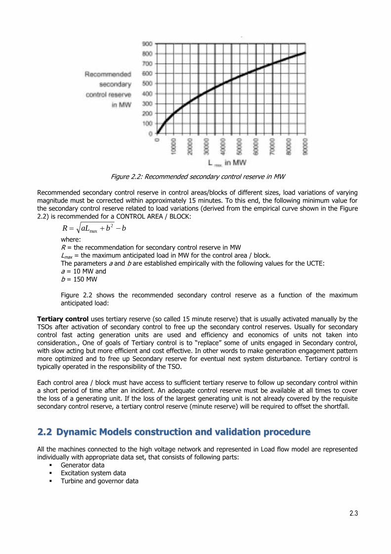
Figure 2.2: Recommended secondary control reserve in MW
Recommended secondary control reserve in control areas/blocks of different sizes, load variations of varying
magnitude must be corrected within approximately 15 minutes. To this end, the following minimum value for the secondary control reserve related to load variations (derived from the empirical curve shown in the Figure
2.2) is recommended for a CONTROL AREA / BLOCK:
bbaLR 2
max
where:
R = the recommendation for secondary control reserve in MW Lmax = the maximum anticipated load in MW for the control area / block.
The parameters a and b are established empirically with the following values for the UCTE: a = 10 MW and
b = 150 MW
Figure 2.2 shows the recommended secondary control reserve as a function of the maximum
anticipated load:
Tertiary control uses tertiary reserve (so called 15 minute reserve) that is usually activated manually by the TSOs after activation of secondary control to free up the secondary control reserves. Usually for secondary
control fast acting generation units are used and efficiency and economics of units not taken into
consideration., One of goals of Tertiary control is to “replace” some of units engaged in Secondary control, with slow acting but more efficient and cost effective. In other words to make generation engagement pattern
more optimized and to free up Secondary reserve for eventual next system disturbance. Tertiary control is typically operated in the responsibility of the TSO.
Each control area / block must have access to sufficient tertiary reserve to follow up secondary control within a short period of time after an incident. An adequate control reserve must be available at all times to cover
the loss of a generating unit. If the loss of the largest generating unit is not already covered by the requisite secondary control reserve, a tertiary control reserve (minute reserve) will be required to offset the shortfall.
22..22 DDyynnaammiicc MMooddeellss ccoonnssttrruuccttiioonn aanndd vvaalliiddaattiioonn pprroocceedduurree
All the machines connected to the high voltage network and represented in Load flow model are represented individually with appropriate data set, that consists of following parts:
Generator data Excitation system data
Turbine and governor data

2.4
In order to have more accurate and reliable dynamic model, it is useful to model other system characteristics,
such as:
Parameters and characteristics of load-frequency control with list of generators taking part into this control,
Load shedding schemes, Demand behaviour, etc
Model integrator has prepared adequate questionnaire for dynamic data collection, and each project participant have sent their data according to it. Using this data, Model integrator constructed data base that is
used for dynamic model preparation. For all new generator units and units for which data is not available for some reason, typical parameters or production units construction data (if available) are used.
2.2.1 Construction of models for dynamic analyses
Based on data collected and data base constructed, each project participant prepared dynamic model of their
system and provided it to model integrator to make regional dynamic model.
Obligations of model integrator concerning this item are as follows: Review all collected data to check that they conform to the agreed numbering systems for areas,
zones and busses, and questionnaire format Provide consultancy for isolated model building to the project participants
Review and test operation of respective isolated models for each system
Merge all model data in order to form one model Test the operation of the regional model
Prepare a Regional model report that consist of: o Summary data for regional model
o Characteristics of the regional model
o Dynamic Data base Distribute regional model to all participants
Regional Dynamic model and data base is prepared based on the most recent version of load flow models for
following regimes: Winter Peak
Summer Peak
Summer Off-Peak where each of these regime is modeled for following target years:
2015 2020
Dynamic Regional model consist of following parts: Load flow model in PSS/E format (*.sav file)
Dynamic model in PSS/E format (*.dyr file) that corresponds to Load flow file Auxiliary PSS/E files necessary for model running (*.dll, *.flx or other, if necessary)
Dynamic model is developed in the most recent version of the PSS/E (currently, the version is 33). USAID and USEA provided full PSS/E program support to all project participants in order to accomplish model building.
EKC experts have build adequate dynamic models for Russian and Ukrainian build excitation systems that can and will be used by all participating parties in project.
The influence of external system is included by modeling of equivalent generators on border of system of
interest.
2.2.2 Verification of model for dynamic analyses
Verification of dynamic model is performed on two levels. The first level (also known as the machine level) includes testing of particular controllers of a single generator unit in an isolated operation (excitation system
test and turbine governor response test). Results of these tests should correspond to a certain standard responses required for the standard types of input signals applied (disturbances).

2.5
Figure 2.3: Example of comparison of Open circuit test for a excitation system and requirements if IEEE standard
Figure 2.4: Example of comparison of governor response test for a turbine-governor and example of actual
system frequency measurement
2.6
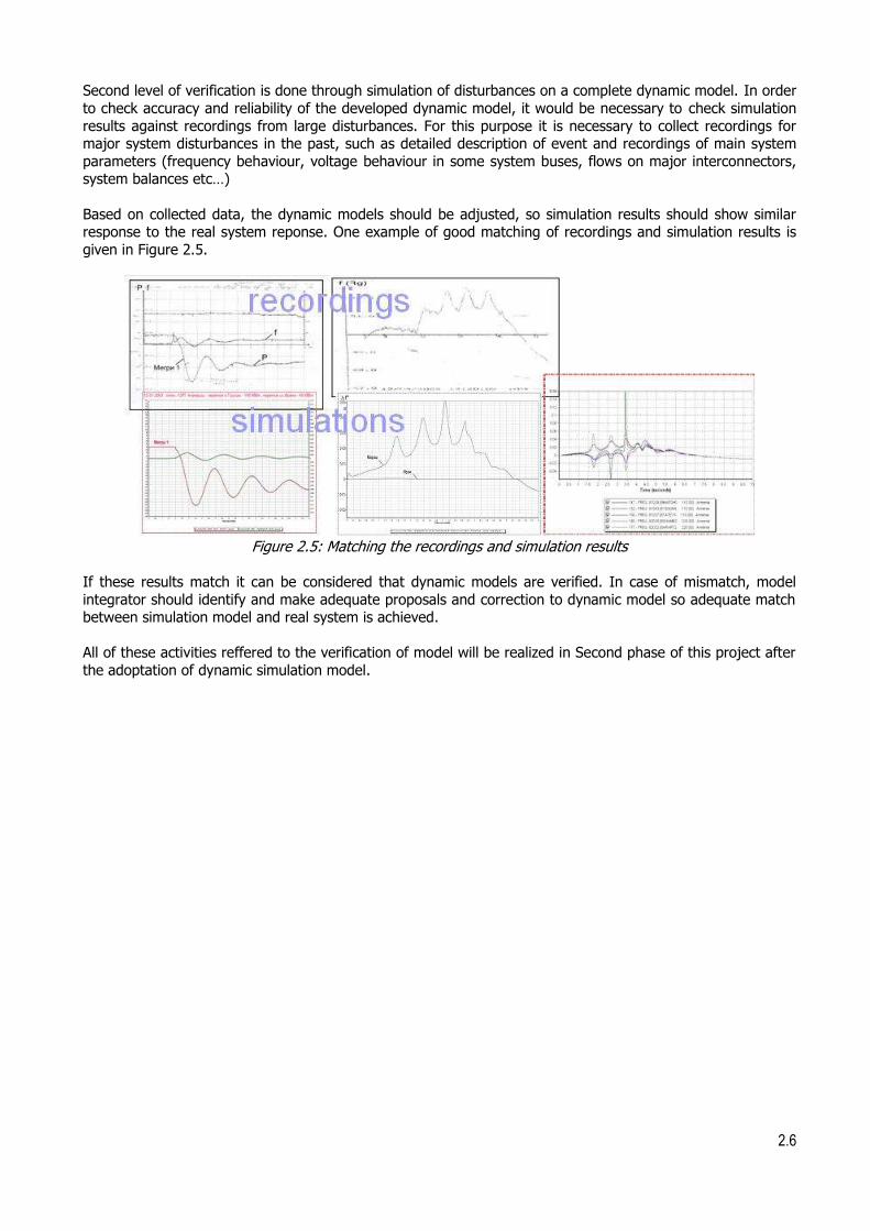
Second level of verification is done through simulation of disturbances on a complete dynamic model. In order
to check accuracy and reliability of the developed dynamic model, it would be necessary to check simulation
results against recordings from large disturbances. For this purpose it is necessary to collect recordings for major system disturbances in the past, such as detailed description of event and recordings of main system
parameters (frequency behaviour, voltage behaviour in some system buses, flows on major interconnectors, system balances etc…)
Based on collected data, the dynamic models should be adjusted, so simulation results should show similar response to the real system reponse. One example of good matching of recordings and simulation results is
given in Figure 2.5.
Figure 2.5: Matching the recordings and simulation results
If these results match it can be considered that dynamic models are verified. In case of mismatch, model
integrator should identify and make adequate proposals and correction to dynamic model so adequate match between simulation model and real system is achieved.
All of these activities reffered to the verification of model will be realized in Second phase of this project after
the adoptation of dynamic simulation model.

3.1
33 CCOONNSSTTRRUUCCTTIIOONN OOFF DDYYNNAAMMIICC MMOODDEELL
In the process of construction of the dynamic model several approaches, data harmonization and compatibility checks have been performed.
The dynamic model is developed in the well known software package PSS/E. The description of the PSS/E is given in Appendix A. This description includes information about the most common used dynamic models of
excitation and turbine/governor controllers) which are part of PSS/E dynamic model library. Dynamic model is developed in the most recent version of the PSS/E (currently, the version is 33).
Information about power systems included in model are given in Appendix B. These information as shown per country/TSO and consist of network reinforcement plans, generation expansion plans, short description of the
most important power plants,…
Dynamic model for SECI project basically consists of plant controller parameters (generator, excitation
system, turbine governor, power system stabilizer etc.) and these data are superimposed on the load flow case to provide power flow input for the time domain simulations and solution of differential equations.
In essence, SECI dynamic model consists of particular dynamic models of SECI members and surrounding countries and it is fully corresponding to the latest version of SECI regional load flow model. The model is
universal, so it can be used for all elaborated load flow cases (different regional level system consumption and topology changes).
Complete country models which are incorporated into the SECI dynamic model are developed for:
Albania
Austria
Bosnia & Herzegovina
Bulgaria
Croatia
Hungary
Romania
Slovenia
Serbia
Kosovo*
Modeling of power plants for Austria and Hungary was performed in concordance with the load flow model of
these countries where there are only power plants connected directly to 400 kV and 220 kV voltage level
without step-up transformers.
Dynamic model of Greece is made in almost complete form. All major power plants were modelled except for the few smaller ones for which there was no information about the type. These unknown small power plants
were converted into negative load.
Due to the fact that the full dynamic model of Italy is not available at the moment, only the northern part of
Italy along with the border towards Austria and Slovenia was modeled. The rest of Italy was represented by equivalent generators. These equivalent generators should represent dynamic response of Italy as well as of
one part of ENTSO-E interconnection.
Similar approach was made regarding Turkey, where there was a suitable topology of the power system
which enabled the modeling of European part only (full dynamic model of Turkish power system is not available). The Asian part of Turkey has been represented by equivalent generators.

3.2
Along the border of SECI model (load flow cases) equivalent generators were put in the dynamic model to
represent the connection of SECI countries to the rest of ENTSO-E interconnection. These equivalents are
situated on borders:
Austria – Switzerland
Austria – Germany
Austria – Czech Republic
Hungary – Slovakia
Hungary – Ukraine
Romania - Ukraine
Compatibility of regional dynamic model with the latest regional load flow model is established through the identification and use of load flow parameters assigned to each generator (Figure 3.1), and these are:
- Generator bus number - Generator ID (two character number or a sign)
- MVA base of generator - Rsource and Xsource of generator (should be equal to subtransient reactance of generator)
These parameters are essential for the dynamic model since through them, PSS/E establishes a connection of dynamic model data and load flow calculation results.
Figure 3.1: Network data sheet for load flow data entry for generators in PSS/E
Regarding the dynamic model itself, it can be built through the dialogs of main window of the software, but the most common way is (still) to build it by building an ASCII format file, in which dynamic controllers and
generator models are being called from the dynamic library of PSS/E for every generator unit, with certain bus number and Id symbol, given in the corresponding load flow case. All dynamic data are eventually stored in
editable ASCII file with extension *.dyr, also known as the DYRE file.
3.3
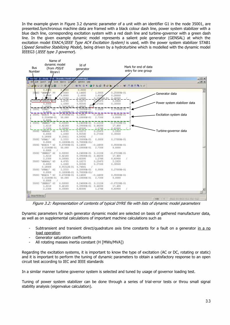
In the example given in Figure 3.2 dynamic parameter of a unit with an identifier G1 in the node 35001, are
presented.Synchronous machine data are framed with a black colour dash line, power system stabilizer with a
blue dach line, corresponding excitation system with a red dash line and turbine-governor with a green dash line. In the given example dynamic model represents a salient pole generator (GENSAL) at which the
excitation model EXAC4(IEEE Type AC4 Excitation System) is used, with the power system stabilizer STAB1 (Speed Sensitive Stabilizing Model), being driven by a hydroturbine which is modelled with the dynamic model
IEEEG3 (IEEE type 3 governor).
Figure 3.2: Representation of contents of typical DYRE file with lists of dynamic model parameters
Dynamic parameters for each generator dynamic model are selected on basis of gathered manufacturer data, as well as on supplemental calculations of important machine calculations such as
- Subtransient and transient direct/quadrature axis time constants for a fault on a generator in a no load operation
- Generator saturation coefficients - All rotating masses inertia constant (H [MWs/MVA])
Regarding the excitation systems, it is important to know the type of excitation (AC or DC, rotating or static) and it is important to perform the tuning of dynamic parameters to obtain a satisfactory response to an open
circuit test according to IEC and IEEE standards
In a similar manner turbine governor system is selected and tuned by usage of governor loading test.
Tuning of power system stabilizer can be done through a series of trial-error tests or throu small signal
stability analysis (eigenvalue calculation).
Generator data
Power system stabilizer data
Excitation system data
Turbine-governor data
Bus Number
Id of generator
Name of dynamic model
(from PSS/E library)
Mark for end of data
entry for one group

3.4
Constructed dynamic model has been deliverd in electronic form in PSS/E format. Load flow models of all six
regimes are in binary format (*.sav files) and dynamic model is in format of ASCII text file (*.dyr file). The
dynamic model in ASCII format (*.dyr file) is common for all six load flow models.
List of generators included in dynamic model, with all data included in dynamic model is given in Appendix C.
These data in Appendix C are per country/TSO.

4.1
44 RREESSUULLTTSS OOFF PPRREELLIIMMIINNAARRYY TTEESSTTIINNGG
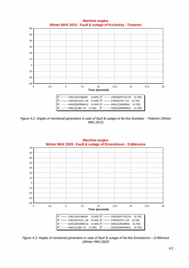
In order to check developed dynamic models several simulations have been performed and system response is shown. In this document simulation results of following disturbances are shown:
Fault and outage of tie-line 400 kV Kozlodoy (BG) – Tintareni (RO)
Fault and outage of tie-line 400 kV Erenstinovo (HR) – Sremska Mitrovica (RS)
Both faults appear after 1 second of monitoring period, fault duration is 100 ms and fault is cleared by tripping-off the faulted line. Monitoring period is 20 s.
Both disturbances are simulated in Winter Peak regimes in 2015 and 2020.
From simulation results, which are shown in Figure 4.1, Figure 4.2, Figure 4.3 and Figure 4.4 it can be seen that osculattions, which appear as result of disturbance, are dumped which can lead to conclusion that the dynamic models are stable.
Machine angles
Winter MAX 2015 - Fault & outage of Ernestinovo - S.Mitrovica
109011[AKOMAN9 13.800]gfedcb 136035[WTTUZLG5 15.750]gfedcb149010[VKOZL_N0 24.000]gfedcb 379002[YBT 2 G2 15.750]gfedcb449332[RCERNAG2 24.000]gfedcb 469011[JHDJERH1 15.750]gfedcb499011[LNEK N1 21.000]gfedcb 169051[HRHEOBG1 15.750]gfedcb
Time (seconds)
2017,51512,5107,552,50
60
50
40
30
20
10
0
-10
-20
-30
Figure 4.1: Angles of monitored generators in case of fault & outage of tie-line Erenstinovo – S.Mitrovica (Winter MAX 2015)
4.2
Machine angles
Winter MAX 2015 - Fault & outage of Kozlodoy - Tintareni
109011[AKOMAN9 13.800]gfedcb 136035[WTTUZLG5 15.750]gfedcb149010[VKOZL_N0 24.000]gfedcb 379002[YBT 2 G2 15.750]gfedcb449332[RCERNAG2 24.000]gfedcb 469011[JHDJERH1 15.750]gfedcb499011[LNEK N1 21.000]gfedcb 169051[HRHEOBG1 15.750]gfedcb
Time (seconds)
2017,51512,5107,552,50
60
50
40
30
20
10
0
-10
-20
-30
Figure 4.2: Angles of monitored generators in case of fault & outage of tie-line Kozlodoy - Tintareni (Winter MAX 2015)
Machine angles
Winter MAX 2020 - Fault & outage of Ernestinovo - S.Mitrovica
109011[AKOMAN9 13.800]gfedcb 136035[WTTUZLG5 15.750]gfedcb149010[VKOZL_N0 24.000]gfedcb 379002[YBT 2 G2 15.750]gfedcb449332[RCERNAG2 24.000]gfedcb 469011[JHDJERH1 15.750]gfedcb499011[LNEK N1 21.000]gfedcb 169051[HRHEOBG1 15.750]gfedcb
Time (seconds)
2017,51512,5107,552,50
70
60
50
40
30
20
10
0
-10
-20
-30
-40
Figure 4.3: Angles of monitored generators in case of fault & outage of tie-line Erenstinovo – S.Mitrovica (Winter MAX 2020)

4.3
Machine angles
Winter MAX 2020 - Fault & outage of Kozlodoy - Tintareni
109011[AKOMAN9 13.800]gfedcb 136035[WTTUZLG5 15.750]gfedcb149010[VKOZL_N0 24.000]gfedcb 379002[YBT 2 G2 15.750]gfedcb449332[RCERNAG2 24.000]gfedcb 469011[JHDJERH1 15.750]gfedcb499011[LNEK N1 21.000]gfedcb 169051[HRHEOBG1 15.750]gfedcb
Time (seconds)
2017,51512,5107,552,50
70
60
50
40
30
20
10
0
-10
-20
-30
-40
Figure 4.4: Angles of monitored generators in case of fault & outage of tie-line Kozlodoy - Tintareni (Winter MAX 2020)

5.1
55 FFIINNDDIINNGGSS AANNDD NNEEXXTT SSTTEEPPSS
The objective of this study was to develop dynamic model of the SECI region. All the activities in this process can be summoned into following findings:
Regional dynamc model corresponding to the latest regional SECI load flow model was developed for
target years 2015 and 2020.
The model is consisted of complete dynamic models per country for detailed country models which
are incorporated into the SECI dynamic model are developed for Albania, Austria, Bosnia &
Herzegovina, Bulgaria, Croatia, Hungary, Romania, Slovenia, Serbia and Kosovo*.
Dynamic model of Turkey, was included into regional model, for European part only, partly due to the
suitable topology of the power system and mainly due to the fact that full dynamic model of Turkish
power system is not available.
Almost complete dynamic model of Greece was made, where all major power plants were modelled,
except for the few smaller ones for which there was no information about the type. These unknown small power plants were converted into negative load.
Dynamic equivalents were used to represent borders of Slovenia, Austria, Hungary and Romania to
model the interconnection with ENTSOe and Ukraine.
Preliminary simulations of standard type disturbances (three phase fault on a tie-lines) were
performed in order to analyse the responsiveness of the dynamic model and the results have proven
to be acceptable at this stage
Due to the fact that there are still dynamic data missing for several key countries in the region and SECI
project, the development of dynamic model at this stage should be considered as a “work in progress“. After the completion of the dynamci model at this stage, further activities that are imposing themselves include:
Fine tuning of dynamic parameters for particular plant controllers;
Special attention to the modelling of “Russian school“ controller which are still quite present in
countries of the region;
Selection of characteristic critical disturbances in the region for further dynamic analyses;
Investigation of actual and historical events that had occured and their simulation in order to achieve
verification of the developed models.

6.1
66 RREEFFEERREENNCCEESS
[1] “UCTE Operation Handbook”; UCTE; 2011.
[2] “Annual Energy Outlook 2009 (revised)”; Energy Information Administration; April 2009
[3] “Power plant engineering”; A.K. Raja, A.P. Srivastava, M.Dwivedi; New Age International (P)
Ltd., Publishers; 2006
[4] “Projected costs of Generating Electricity”; International Energy Agency, Nuclear Energy
Agency ; 2005
[5] “Comparison of Electricity Generation Costs”; LAPPEENRANTA UNIVERSITY OF TECHNOLOGY
; 2008
[6] “A Review of Electricity Unit cost estimates”; UKERC ; 2008
[7] “Projected Costs of Generating Electricity”; WADE ; 2006
[8] “The Costs of Generating”; Royal Academy of Engineering ; 2005
[9] “US Energy overview-Electric Power Monthly”; U.S. Department of Energy - Energy
Information Administration ; 2009
[10] “PSS/E 33 Documentation”, PTI-Siemens, May 2011
[11] “Power System Stability and Control”, P. S. Kundur, McGraw Hill Inc., New York 1994.
[12] “NARUC Black Sea activity and RES Country Profiles”, NARUC, USAID; 2011.
Recommended