Original operating instructions
© Lutz-Jesco GmbH 2017
BA-12501-02-V04
Back-pressure and pressure relief valves
Operating instructions
Read the operating manual!
The user is responsible for installation and operation related mistakes!
DosingConveying
Control
Liquids
Gases
Systems

Table of Contents 3© Lutz-Jesco GmbH 2017Subject to technical changes.171025
BA-12501-02-V04
Back-pressure and pressure relief valves Operating instructions
Table of Contents1 Notes for the Reader ..........................................................4
1.1 General non-discrimination ......................................................41.2 Explanation of the signal words ................................................41.3 Explanation of the warning signs ..............................................41.4 Identification of warnings .........................................................41.5 Instruction for action identification ...........................................4
2 Safety .................................................................................52.1 General warnings .....................................................................52.2 Hazards due to non-compliance with the safety instructions .....62.3 Working in a safety-conscious manner .....................................62.4 Personal protective equipment .................................................62.5 Personnel qualification .............................................................6
3 Intended use ......................................................................83.1 Notes on product warranty .......................................................83.2 Intended purpose .....................................................................83.3 Explosive risk zone ...................................................................83.4 Principles ................................................................................8
4 Product description ...........................................................9
5 Technical data ..................................................................10
6 Dimensions ......................................................................116.1 Valves DN6 - DN15 (spring-loaded diaphragm valve) ..............116.2 Valves DN25 - DN65 (spring-loaded diaphragm valve) ............126.3 Pressure-relief valve DN6 (spring-loaded seat valve) ..............136.4 Pressure-relief valves DN 10 (spring-loaded seat valve) ..........136.5 Mounting block DN6 ..............................................................146.6 Mounting block DN10 – DN15 ................................................15
7 Installation .......................................................................16
8 Operation ..........................................................................17
9 Maintenance ....................................................................189.1 Valves DN6 - DN15 (spring-loaded diaphragm valve) ..............189.2 Valves DN25 - DN65 (spring-loaded diaphragm valve) ............19
10 Spare parts .......................................................................2010.1 Diaphragms .........................................................................2010.2 Seals ...................................................................................2010.3 Seats for pressure-relief valve DN6 ......................................20
11 Declaration of Incorporation ............................................21
12 Declaration of no objection ..............................................22
13 Warranty claim .................................................................23
Notes for the ReaderInstruction for action identification
4 © Lutz-Jesco GmbH 2017BA-12501-02-V04
Back-pressure and pressure relief valves Operating instructions
1 Notes for the ReaderThis operating manual contains information and behaviour rules for the safe and designated operation of the product.
Observe the following principles:
nRead the entire operating manual prior to starting-up the device.nensure that everyone who works with or on the product has read the
operating manual and follows the instructions.nmaintain the operating manual throughout the service life of the
product.npass the operating manual on to any subsequent owner of the
product.
1.1 General non-discriminationIn this operating manual, only the male gender is used where grammar allows gender allocation. The purpose of this is to make the text easy to read. Men and women are always referred to equally. We would like to ask female readers for understanding of this text simplification.
1.2 Explanation of the signal wordsDifferent signal words in combination with warning signs are used in this operating manual. Signal words illustrate the gravity of possible injuries if the risk is ignored:
Signal word Meaning
DANGERRefers to imminent danger. Ignoring this sign may lead to death or the most serious injuries.
WARNINGRefers to a potentially hazardous situation. Failure to follow this instruction may lead to death or severe injuries.
CAUTIONRefers to a potentially hazardous situation. Failure to follow this instruction may lead to minor injury or damage to property.
NOTE Refers to a danger which, if ignored, may lead to risk to the machine and its function.
Table 1: Explanation of the signal words
1.3 Explanation of the warning signsWarning signs represent the type and source of a danger:
Warning sign Type of danger
Danger point
Danger from potentially-explosive substances
Danger from corrosive substances
Danger of damage to machine or functional influences
Table 2: Explanation of the warning signs
1.4 Identification of warnings
Warnings are intended to help you recognise risks and avoid negative consequences.
This is how warnings are identified:
Warning sign SIGNAL WORD
Description of danger.Consequences if ignored.
ðThe arrow signals a safety precaution to be taken to eliminate the danger.
1.5 Instruction for action identificationThis is how pre-conditions for action are identified:
üPre-condition for action which must be met before taking action.
@A resource such as a tool or auxiliary materials required to perform the operating instructions.
This is how instructions for action are identified:
èSeparate step with no follow-up action.
1. First step in a series of steps.
2. Second step in a series of steps.4Result of the above action.
üAction completed, aim achieved.
SafetyGeneral warnings
5© Lutz-Jesco GmbH 2017Subject to technical changes.171025
BA-12501-02-V04
Back-pressure and pressure relief valves Operating instructions
2 Safety2.1 General warnings
The following warnings are intended to help you to eliminate the dangers that can arise while handling the product. Risk prevention measures al-ways apply regardless of any specific action.
Safety instructions warning against risks arising from specific activities or situations can be found in the respective sub-chapters.
DANGER
Danger to life through explosions!The use of devices and fittings without ATEX certification in a potentially explosive atmosphere can result in potentially-fatal explosions.
ðNever use devices and fittings without ATEX certification in a potentially-explosive atmosphere.
WARNING
Caustic burns or other burns through dosing media!While working on the dosing head, valves and connections, you may come into contact with dosing media.
ðUse sufficient personal protective equipment.
ðRinse the dosing pump with a liquid (e.g. water) which does not pose any risk. Ensure that the liquid is compatible with the dosing medium.
ðRelease pressure in hydraulic parts.
ðNever look into open ends of plugged pipelines and valves.
WARNING
Danger from unsuitable materialsThe materials of the product and hydraulic parts of the system must be suitable for the dosing medium used. Should this not be the case, the dosing media may leak.
ðMake sure that the materials you are using are suitable for the dosing medium.
ðMake sure that the lubricants, adhesives, sealants, etc. that you use are suitable for the dosing medium.
WARNING
Danger from too high a pressure!All devices and hydraulic fittings on the dosing system must be operated below the maximum permissible pressure. Overly-high pressure peaks can result in the bursting of system parts, the release of dosing medium and injury.
ðSet the pre-tension pressure of the back-pressure and pres-sure-relief valves so that the pressure during maximum through-flow is does not exceed that permitted for the dosing pump or other devices.
ðDo not insert the back-pressure and pressure-relief valves with non-adjustable pre-tension pressure in the dosing system under any operating conditions other than those specified in the order. Check the information on the type plate for this purpose.
ðAfter installation, adjust the back-pressure and pressure-relief valves with adjustable pre-tension pressure to the operating conditions of the system.
CAUTION
Danger when changing the dosing medium!Changing the dosing media can provoke unexpected reactions, damage to property and injury.
ðClean the product and the system parts in contact with the media thoroughly before changing the dosing medium.
CAUTION
Increased risk of accidents due to insufficient qualifica-tion of personnel!Dosing pumps and their accessories may only be installed, operated and maintained by personnel with sufficient qualifications. Insufficient qualification will increase the risk of accidents.
ðEnsure that all action is taken only by personnel with sufficient and corresponding qualifications.
ðPrevent access to the system for unauthorised persons.
SafetyPersonnel qualification
6 © Lutz-Jesco GmbH 2017BA-12501-02-V04
Back-pressure and pressure relief valves Operating instructions
NOTE
Damage from incorrect use as a back-pressure valveDamage from incorrect use as a back-pressure valve
Stainless steel (1.4571) spring-loaded seat valves may not be used as a back-pressure valve. Its use as a back-pressure valve increases wear and shortens the lifetime of the valve.
ðUse the stainless steel (1.4571) spring-loaded seat valve as a pressure-relief valve only.
2.2 Hazards due to non-compliance with the safety instructionsFailure to follow the safety instructions may endanger not only persons, but also the environment and the device.
The specific consequences can be:
nFailure of major functions of the product.nfailure of required maintenance and repair methods,ndanger for individuals through dangerous dosing media,ndanger to the environment caused by substances leaking from the
system.
2.3 Working in a safety-conscious mannerBesides the safety instructions specified in this operating manual, further safety rules apply and must be followed:
naccident prevention regulationsnsafety and operating provisions,nsafety provisions for handling dangerous substances (mostly the
safety data sheets to dosing media),nenvironmental protection provisions,napplicable standards and legislation.
2.4 Personal protective equipmentBased on the degree of risk posed by the dosing medium and the type of work you are carrying out, you must use corresponding protective equip-ment. Read the Accident Prevention Regulations and the Safety Data Sheets to the dosing media find out what protective equipment you need.
You will require the minimum of the following personal protective equip-ment:
Personal protective equipment required
Protective goggles
Protective clothing
Protective gloves
Table 3: Personal protective equipment required
Wear the following personal protective equipment when performing the following tasks:
nCommissioning,nWorking on the product during operation,nShut-down,nMaintenance work,nDisposal.
2.5 Personnel qualificationAny personnel who work on the product must have appropriate special knowledge and skills.
Anybody who works on the product must meet the conditions below:
nattendance at all the training courses offered by the owner,npersonal suitability for the respective activity,nsufficient qualification for the respective activity,ntraining into the handling of the device,nknowledge of safety equipment and the way this equipment functions,nknowledge of this operating manual, particularly of safety instructions
and sections relevant for the activity,nknowledge of fundamental regulations regarding health and safety
and accident prevention.
All persons must generally have the following minimum qualification:
ntraining as specialists to carry out work on the product unsupervised,nsufficient training that they can work on the product under the
supervision and guidance of a trained specialist.
SafetyPersonnel qualification
7© Lutz-Jesco GmbH 2017Subject to technical changes.171025
BA-12501-02-V04
Back-pressure and pressure relief valves Operating instructions
These operating instructions differentiate between these user groups:
2.5.1 Specialist staffThanks to their professional training, knowledge, experience and knowl-edge of the relevant specifications, specialist staff are able to perform the job allocated to them and recognise and/or eliminate any possible dan-gers by themselves.
2.5.2 Trained personsTrained persons have received training from the operator about the tasks they are to perform and about the dangers stemming from improper be-haviour.
In the table below you can check what qualifications are the pre-condi-tion for the respective tasks. Only people with appropriate qualifications are allowed to perform these tasks!
Qualification Activities
Specialist staff nAssemblynHydraulic installationsnElectrical installationnMaintenancenRepairsnCommissioningnTaking out of operationnDisposalnFault rectification
Trained persons nStoragenTransportationnControlnFault rectification
Table 4: Personnel qualification
Intended usePrinciples
8 © Lutz-Jesco GmbH 2017BA-12501-02-V04
Back-pressure and pressure relief valves Operating instructions
3 Intended use
3.1 Notes on product warranty
Any non-designated use of the product can compromise its function or intended protection. This leads to invalidation of any warranty claims!
Please note that liability is on the side of the user in the following cases:
nthe device is operated in a manner which is not consistent with this operating manual, particularly safety instructions, handling instruc-tions and the section "Intended Use".
nIf people operate the product who are not adequately qualified to carry out their respective activities,
nNo original spare parts or accessories are used,nUnauthorised changes are made to the device by the user,nThe user uses different dosing media than those indicated in the
order,nThe user does not use dosing media under the conditions agreed with
the manufacturer such as modified concentration, density, tempera-ture, contamination, etc.
3.2 Intended purpose
Back-pressure and pressure-relief valves are fittings for dosing systems Depending on the task involved, they are used to increase the dosing ac-curacy or to protect the system against excess pressure.
3.2.1 Use as a back-pressure valve
With the dosing of fluids, back-pressure valves generate a defined back pressure on the pressure side of a dosing pump.
This is required in the following cases:
nStrongly fluctuating pressure. Exact dosing results are impossible without a back-pressure valve.
nThe pressure on the suction side is higher than on the pressure side.nDosing in a pressureless line is required.
3.2.2 Use as a pressure-relief valve
Pressure relief valves have an important safety function for protecting the dosing pump and the associated pipes and fittings. The dosing pump can generate a pressure that is many times the rated one.
Various reasons, e.g. soiling or operating errors can result in blocked pressure lines. At an appropriate pressure, a pressure relief valve opens a bypass line and protects the system in this way from damage caused by over-pressure.
3.3 Explosive risk zone
The type DN6, 200 bar and DN10, 250 bar spring-loaded seat valves can be deployed in potentially-explosive atmospheres. They may only be used as pressure-relief valves.
All other back-pressure and pressure-relief valves may not be used in a potentially explosive atmosphere.
3.4 PrinciplesnBack-pressure and pressure-relief valves may not be used as
non-return valves.nBack-pressure and pressure-relief valves may not be used as shutoff
valves.nComply with the information regarding the operating and environmen-
tal conditions (see 5 “Technical data” on page 10).nAny restrictions regarding the viscosity, temperature and density of
dosing media must be followed. You must only use dosing media at temperatures above freezing point or below the boiling point of the respective medium.
nThe specified flow capacity (see 5 “Technical data” on page 10) applies to uniform flows of water and other liquids, which are comparable to water in terms of viscosity and density, given dosing with a sufficiently-apportioned pulsation damper. An uneven flow without a pulsation damper can result in a far lower flow capacity.
nThe materials of the product and hydraulic parts of the system must be suitable for the dosing medium used. In this connection, note that the resistance of these components can change in dependence on the temperature of the media and the operating pressure.
i Information on the suitability of materials combined with different dosing media can be found in the Compatibility Chart of the manufacturer.The information in this resistance list is based on information from the material manufacturers and on expertise obtained from handling the materials.As the durability of the materials depends on many factors, this list only constitutes initial guidance on selecting material. In all cases, test the equipment with the chemicals you use under operating conditions.
Product descriptionPrinciples
9© Lutz-Jesco GmbH 2017Subject to technical changes.171025
BA-12501-02-V04
Back-pressure and pressure relief valves Operating instructions
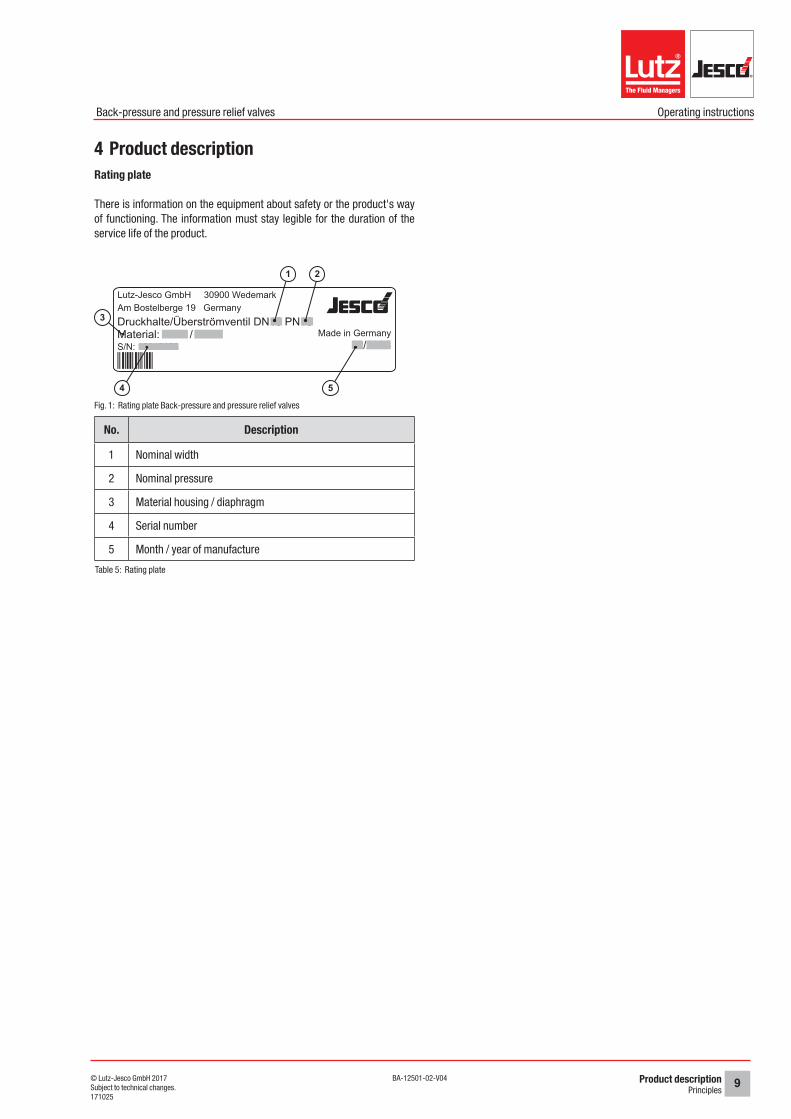
4 Product descriptionRating plate
There is information on the equipment about safety or the product's way of functioning. The information must stay legible for the duration of the service life of the product.
Lutz-Jesco GmbH 30900 Wedemark Am Bostelberge 19 GermanyDruckhalte/Überströmventil DN16 PN16Material: X X / XXX
12/2008S/N: 12345678Made in Germany
45*
Fig. 1: Rating plate Back-pressure and pressure relief valves
No. Description
1 Nominal width
2 Nominal pressure
3 Material housing / diaphragm
4 Serial number
5 Month / year of manufacture
Table 5: Rating plate
5
2
3
4
1
Technical data10 © Lutz-Jesco GmbH 2017BA-12501-02-V04
Back-pressure and pressure relief valves Operating instructions
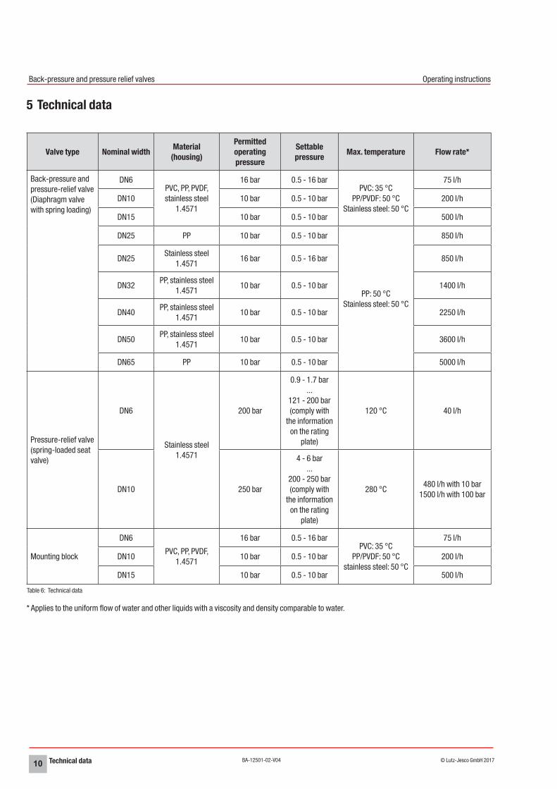
5 Technical data
Valve type Nominal width Material (housing)
Permitted operating pressure
Settable pressure Max. temperature Flow rate*
Back-pressure and pressure-relief valve (Diaphragm valve with spring loading)
DN6PVC, PP, PVDF, stainless steel
1.4571
16 bar 0.5 - 16 barPVC: 35 °C
PP/PVDF: 50 °C Stainless steel: 50 °C
75 l/h
DN10 10 bar 0.5 - 10 bar 200 l/h
DN15 10 bar 0.5 - 10 bar 500 l/h
DN25 PP 10 bar 0.5 - 10 bar
PP: 50 °C Stainless steel: 50 °C
850 l/h
DN25Stainless steel
1.457116 bar 0.5 - 16 bar 850 l/h
DN32PP, stainless steel
1.457110 bar 0.5 - 10 bar 1400 l/h
DN40PP, stainless steel
1.457110 bar 0.5 - 10 bar 2250 l/h
DN50PP, stainless steel
1.457110 bar 0.5 - 10 bar 3600 l/h
DN65 PP 10 bar 0.5 - 10 bar 5000 l/h
Pressure-relief valve (spring-loaded seat valve)
DN6
Stainless steel 1.4571
200 bar
0.9 - 1.7 bar ...
121 - 200 bar (comply with
the information on the rating
plate)
120 °C 40 l/h
DN10 250 bar
4 - 6 bar ...
200 - 250 bar (comply with
the information on the rating
plate)
280 °C480 l/h with 10 bar
1500 l/h with 100 bar
Mounting block
DN6
PVC, PP, PVDF, 1.4571
16 bar 0.5 - 16 barPVC: 35 °C
PP/PVDF: 50 °C stainless steel: 50 °C
75 l/h
DN10 10 bar 0.5 - 10 bar 200 l/h
DN15 10 bar 0.5 - 10 bar 500 l/h
Table 6: Technical data
* Applies to the uniform flow of water and other liquids with a viscosity and density comparable to water.
Dimensions 11© Lutz-Jesco GmbH 2017Subject to technical changes.171025
BA-12501-02-V04
Back-pressure and pressure relief valves Operating instructions
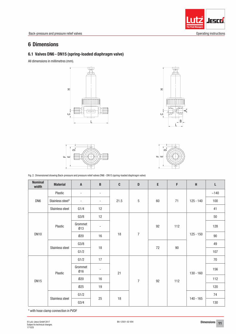
6 Dimensions6.1 Valves DN6 - DN15 (spring-loaded diaphragm valve)All dimensions in millimetres (mm).
Fig. 2: Dimensioned drawing Back-pressure and pressure relief valves DN6 - DN15 (spring-loaded diaphragm valve)
Nominal width Material A B C D E F H L
DN6
Plastic - -
21.5 5 60 71 125 - 140
~140
Stainless steel* - - 100
Stainless steel G1/4 12 41
DN10
Plastic
G3/8 12
18 7
92 112
125 - 150
50
Grommet Ø13
- 128
Ø20 16 90
Stainless steelG3/8
18 72 9049
G1/2 107
DN15
Plastic
G1/2 17
21
7 92 112
130 - 160
70
Grommet Ø16
- 156
Ø20 16 112
Ø25 19 120
Stainless steelG1/2
25 18 140 - 16574
G3/4 130
* with hose clamp connection in PVDF
HC
L
F ED
F ED
H
A
BL
C
Dimensions12 © Lutz-Jesco GmbH 2017BA-12501-02-V04
Back-pressure and pressure relief valves Operating instructions
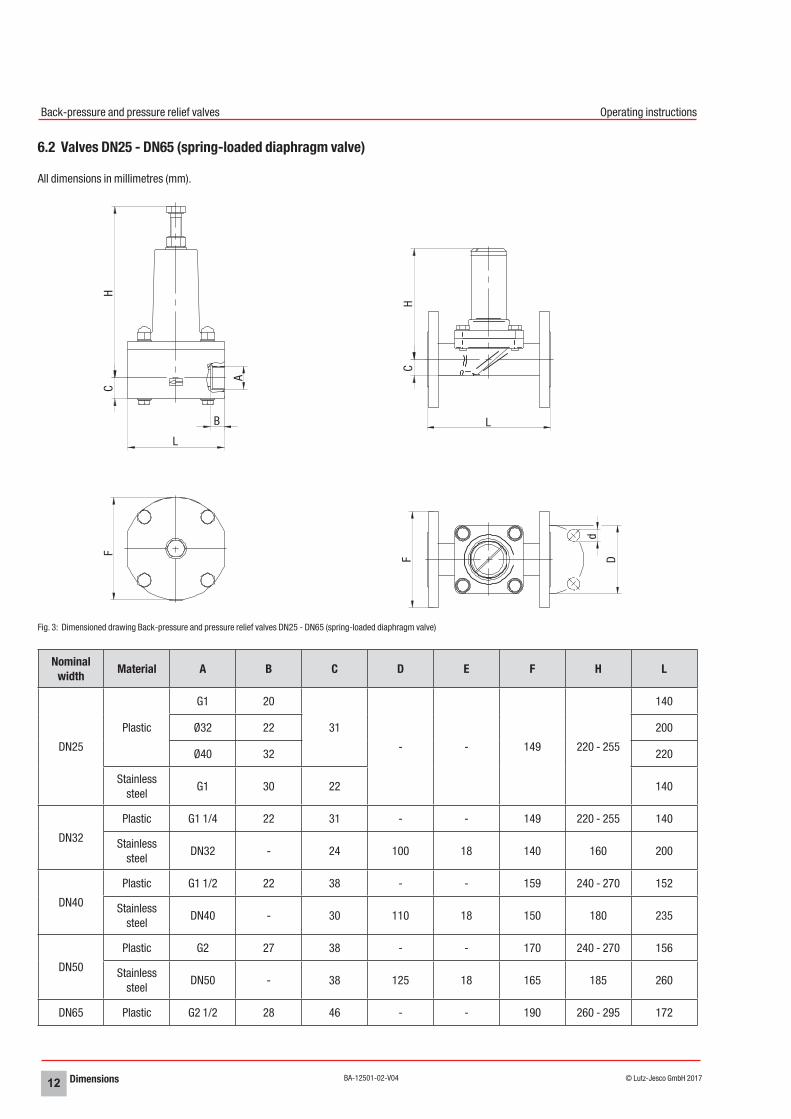
6.2 Valves DN25 - DN65 (spring-loaded diaphragm valve)
All dimensions in millimetres (mm).
Fig. 3: Dimensioned drawing Back-pressure and pressure relief valves DN25 - DN65 (spring-loaded diaphragm valve)
Nominal width Material A B C D E F H L
DN25
Plastic
G1 20
31
- - 149 220 - 255
140
Ø32 22 200
Ø40 32 220
Stainless steel
G1 30 22 140
DN32
Plastic G1 1/4 22 31 - - 149 220 - 255 140
Stainless steel
DN32 - 24 100 18 140 160 200
DN40
Plastic G1 1/2 22 38 - - 159 240 - 270 152
Stainless steel
DN40 - 30 110 18 150 180 235
DN50
Plastic G2 27 38 - - 170 240 - 270 156
Stainless steel
DN50 - 38 125 18 165 185 260
DN65 Plastic G2 1/2 28 46 - - 190 260 - 295 172
HF D
d
CL
L
B
A
HC
F
Dimensions 13© Lutz-Jesco GmbH 2017Subject to technical changes.171025
BA-12501-02-V04
Back-pressure and pressure relief valves Operating instructions
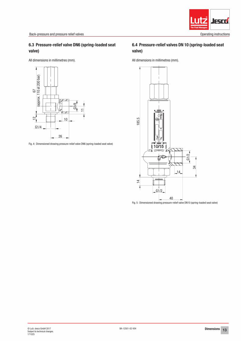
6.3 Pressure-relief valve DN6 (spring-loaded seat valve)
All dimensions in millimetres (mm).
Fig. 4: Dimensioned drawing pressure-relief valve DN6 (spring-loaded seat valve)
6.4 Pressure-relief valves DN 10 (spring-loaded seat valve)
All dimensions in millimetres (mm).
Fig. 5: Dimensioned drawing pressure-relief valve DN10 (spring-loaded seat valve)
(app
rox.
110
at 2
00 b
ar)
67
10
26
G1/4
12
11
G3/8
185.
5
G1/2
34
14
G1/2
40
14
Dimensions14 © Lutz-Jesco GmbH 2017BA-12501-02-V04
Back-pressure and pressure relief valves Operating instructions
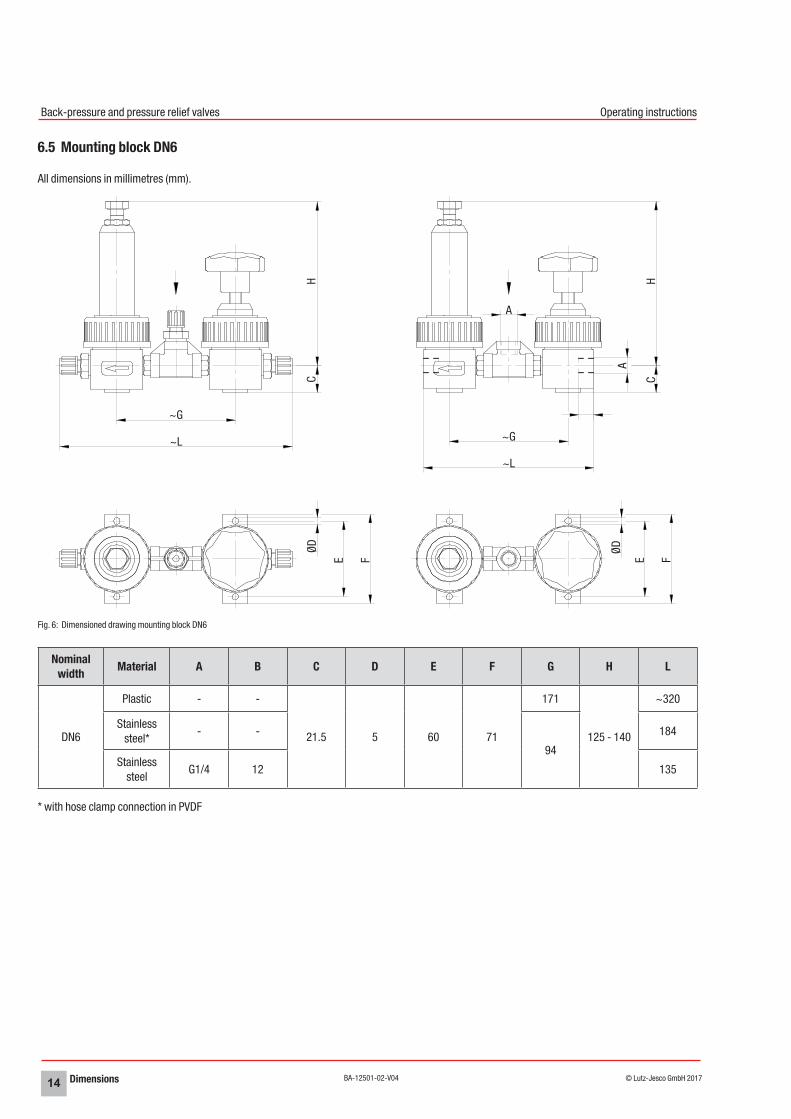
6.5 Mounting block DN6
All dimensions in millimetres (mm).
Fig. 6: Dimensioned drawing mounting block DN6
Nominal width Material A B C D E F G H L
DN6
Plastic - -
21.5 5 60 71
171
125 - 140
~320
Stainless steel*
- -
94
184
Stainless steel
G1/4 12 135
* with hose clamp connection in PVDF
HC
FE
ØD
H
A
CFE
ØD
~G
~L
A
~G
~L
Dimensions 15© Lutz-Jesco GmbH 2017Subject to technical changes.171025
BA-12501-02-V04
Back-pressure and pressure relief valves Operating instructions
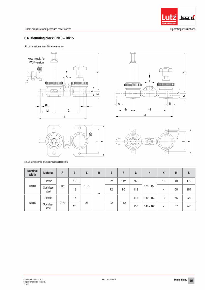
6.6 Mounting block DN10 – DN15
All dimensions in millimetres (mm).
Fig. 7: Dimensioned drawing mounting block DN6
Nominal width Material A B C D E F G H K M L
DN10
Plastic
G3/8
12
18.5
7
92 112 92
125 - 150
10 48 172
Stainless steel
18 72 90 118 - 50 204
DN15
Plastic
G1/2
16
21 92 112
112 130 - 160 12 66 222
Stainless steel
25 136 140 - 165 - 57 240
A
M
A B
A
~G
~L
HC
FE
ØD
ØK
ØK
M ~G
A
~L
ØD
E F
A
CH
Hose nozzle for PVDF version
A
Installation16 © Lutz-Jesco GmbH 2017BA-12501-02-V04
Back-pressure and pressure relief valves Operating instructions
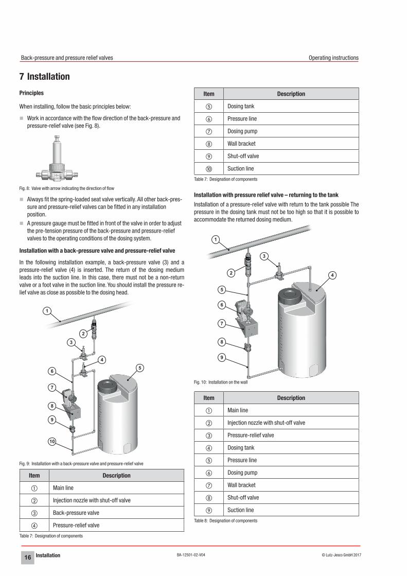
7 InstallationPrinciples
When installing, follow the basic principles below:
nWork in accordance with the flow direction of the back-pressure and pressure-relief valve (see Fig. 8).
Fig. 8: Valve with arrow indicating the direction of flow
nAlways fit the spring-loaded seat valve vertically. All other back-pres-sure and pressure-relief valves can be fitted in any installation position.
nA pressure gauge must be fitted in front of the valve in order to adjust the pre-tension pressure of the back-pressure and pressure-relief valves to the operating conditions of the dosing system.
Installation with a back-pressure valve and pressure-relief valve
In the following installation example, a back-pressure valve (3) and a pressure-relief valve (4) is inserted. The return of the dosing medium leads into the suction line. In this case, there must not be a non-return valve or a foot valve in the suction line. You should install the pressure re-lief valve as close as possible to the dosing head.
Fig. 9: Installation with a back-pressure valve and pressure-relief valve
Item Description
a Main line
b Injection nozzle with shut-off valve
c Back-pressure valve
d Pressure-relief valve
Table 7: Designation of components
Item Description
e Dosing tank
f Pressure line
g Dosing pump
h Wall bracket
i Shut-off valve
j Suction line
Table 7: Designation of components
Installation with pressure relief valve – returning to the tankInstallation of a pressure-relief valve with return to the tank possible The pressure in the dosing tank must not be too high so that it is possible to accommodate the returned dosing medium.
Fig. 10: Installation on the wall
Item Description
a Main line
b Injection nozzle with shut-off valve
c Pressure-relief valve
d Dosing tank
e Pressure line
f Dosing pump
g Wall bracket
h Shut-off valve
i Suction line
Table 8: Designation of components
2
1
3
4
6 5
7
8
9
10
1
2
3
5
6
7
8
9
4
Operation 17© Lutz-Jesco GmbH 2017Subject to technical changes.171025
BA-12501-02-V04
Back-pressure and pressure relief valves Operating instructions
8 Operation
Setting the pre-tension pressure
Precondition for action:
üThe entire system has been installed hydraulically and (if required) electrically.
üAll the mechanical fastenings have been inspected to ensure adequate load-bearing capacity.
üAll the hydraulic sections have been inspected to ensure they are adequately leak-proof and that the through flow direction is correct.
üThe system is fitted with a pressure gauge to read off the operating pressure.
üPersonnel have read all the operating instructions and understood them completely.
i During initial start-up, use water as the dosing medium so as to check the leak-tightness of the system. Check first whether undesirable reactions could occur between the actual dosing medium and the water.
Perform the following working steps:
1. Loosen the counternut on the back-pressure and pressure-relief valve.
2. Turn the pressure setting screw anti-clockwise until it moves freely.
3. Open all the shutoff valves.
4. Startup the dosing pump. Increase the delivery capacity slowly to the required level.
5. Turn the pressure setting screw clockwise slowly.4The operating pressure increases.
When using as a back-pressure valve:
6. Once the desired operating pressure has been reached, screw the counternut clockwise until the pressure setting screw is no longer easy to loosen.
7. Check whether the operating pressure set remains constant over a long period.
When using as a pressure-relief valve:
6. Increase the inlet pressure tension until the pressure-relief valve does not open any further.
7. Turn the pressure setting screw c. half a revolution further to avoid any excess flow resulting from fluctuating operating pressures.
üPre-tension pressure set.
Maintenance18 © Lutz-Jesco GmbH 2017BA-12501-02-V04
Back-pressure and pressure relief valves Operating instructions
9 MaintenanceBack-pressure and pressure relief valves are produced to the highest quality standards, and have a long service life. Nevertheless, some of their parts are subject to wear due to operation (e.g. diaphragms, valve seats, valve balls). This means that regular visual inspections are neces-sary to ensure a long operating life. Regular maintenance will protect the device from operation interruptions.
NOTE
Function of the valve compromisedTightening the union nut by hand means that the sufficient leak-tight-ness of the diaphragm has not been ensured. High pressures cannot be maintained in this fashion.
ðUse a suitable tool to tighten the union nut. Do not use any tools which could damage the components (e.g. a water pump wrench). Should you not have a suitable tool, the valve must be pre-ten-sioned lengthwise e.g. in a vice. The union nut can then be tightened by hand.
9.1 Valves DN6 - DN15 (spring-loaded diaphragm valve)
Fig. 11: Exploded diagram of the back-pressure and pressure-relief valves DN6 - DN15
Perform the following working steps:
1. Loosen the counternut (3) until the pressure setting screw (2) moves freely.
i Measure the clearance of the pressure setting screw from the valve body and note the value. This enables you to set the identical pre-tension pressure after changing the diaphragm.
2. Unscrew the pressure setting screw from the valve cap (4).
3. Loosen the union nut (1).
4. Remove the valve cap.
5. Remove the diaphragm (8), spring plate (7), compression spring (6) and washer (5). Back-pressure and pressure relief valves with diaphragms made of FPM (Viton) and EPDM contain one diaphragm. Back-pressure and pressure relief valves DN6 with diaphragms made of EPDM-PTFE contain two diaphragms (10 and 11. Fig. 12).
Fig. 12: Exploded view of back-pressure and pressure relief valves DN6 with diaphragms made of EPDM-PTFE
6. Clean the valve body (9).
7. Insert a new diaphragm (8 or 11) in the valve body with the coated side facing downwards. Should your back-pressure and pressure-re-lief valve be fitted with two diaphragms, insert an uncoated diaphragm (10) over it.
8. Insert the washer, compression spring and spring plate in the valve cap.
9. Insert the valve cap in the valve body.
10. Screw the union nut onto the valve body.
11. Screw the pressure setting screw in the valve cap with the counter-nut.
12. Set the specific pre-tension pressure.
üDiaphragm has been replaced.
1
7
8
2
4
5
6
9
3
10
11
Maintenance 19© Lutz-Jesco GmbH 2017Subject to technical changes.171025
BA-12501-02-V04
Back-pressure and pressure relief valves Operating instructions
9.2 Valves DN25 - DN65 (spring-loaded diaphragm valve)
Fig. 13: Exploded diagram of the back-pressure and pressure-relief valves DN25 - DN65
Perform the following working steps:
1. Loosen the counternut (2) until the pressure setting screw (1) moves freely.
i Measure the clearance of the pressure setting screw from the valve body and note the value. This enables you to set the identical pre-tension pressure after changing the diaphragm.
2. Unscrew the pressure setting screw from the valve cap (6).
3. Remove the four protective caps (3).
4. Loosen the four hexagon nuts (4).
5. Remove the four washers (5).
6. Remove the valve cap.
7. Remove the diaphragm (10), diaphragm disc (9), compression spring (8) and spring plate (7).
8. Clean the valve body (11).
9. Insert a new diaphragm in the valve body with the coated side facing downwards.
10. Insert the spring plate, compression spring and diaphragm disc in the valve cap.
11. Place the valve cap on the valve body.
12. Insert the four washers.
13. Screw the four hexagon nuts tight. Tighten the hexagonal nuts equally in a criss-cross sequence. Recommended torque: 8 Nm
14. Place the four protective caps on the hexagon nuts
15. Screw the pressure setting screw in the valve cap with the counter-nut.
16. Set the specific pre-tension pressure.
üDiaphragm has been replaced.
1
2
4
5
6
3
7
8
9
10
11
Spare parts20 © Lutz-Jesco GmbH 2017BA-12501-02-V04
Back-pressure and pressure relief valves Operating instructions
10 Spare parts
10.1 Diaphragms
Nominal width
Material (Casing)
Material (Membrane) Part No.
DN6 PVC, PP, PVDF, 1.4571
EPDM-PTFE, PTFE
8190526391
EPDM 81898
FPM 81899
DN10 EPDM-PTFE 81655
81657 (for PVDF version)
DN15 EPDM-PTFE 81656
EPDM 81562
FPM 26394
DN25 - DN65 EPDM-PTFE 81662
EPDM 81263
FPM 81264
10.2 Seals
Material Part number Colour
EPDM 81824 Black
FPM 81825 Green
PTFE 81841 White
10.3 Seats for pressure-relief valve DN6
For stainless steel pressure-relief valve (see 6.3 “Pressure-relief valve DN6 (spring-loaded seat valve)” on page 13).
PVC Size Part No.
0.9 - 90.99 FPM 80085
91 - 200 80792
Declaration of Incorporation 21© Lutz-Jesco GmbH 2017Subject to technical changes.171025
BA-12501-02-V04
Back-pressure and pressure relief valves Operating instructions
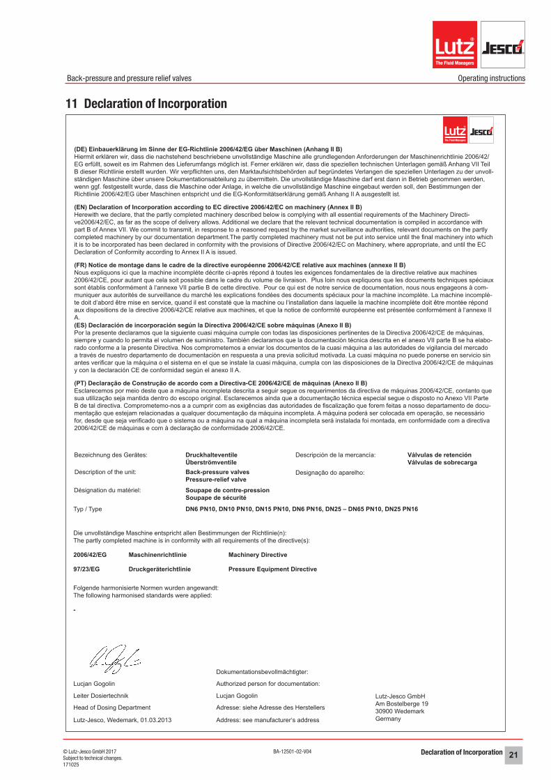
11 Declaration of Incorporation
(DE) Einbauerklärung im Sinne der EG-Richtlinie 2006/42/EG über Maschinen (Anhang II B)Hiermit erklären wir, dass die nachstehend beschriebene unvollständige Maschine alle grundlegenden Anforderungen der Maschinenrichtlinie 2006/42/EG erfüllt, soweit es im Rahmen des Lieferumfangs möglich ist. Ferner erklären wir, dass die speziellen technischen Unterlagen gemäß Anhang VII Teil B dieser Richtlinie erstellt wurden. Wir verpflichten uns, den Marktaufsichtsbehörden auf begründetes Verlangen die speziellen Unterlagen zu der unvoll-ständigen Maschine über unsere Dokumentationsabteilung zu übermitteln. Die unvollständige Maschine darf erst dann in Betrieb genommen werden, wenn ggf. festgestellt wurde, dass die Maschine oder Anlage, in welche die unvollständige Maschine eingebaut werden soll, den Bestimmungen der Richtlinie 2006/42/EG über Maschinen entspricht und die EG-Konformitätserklärung gemäß Anhang II A ausgestellt ist.
(EN) Declaration of Incorporation according to EC directive 2006/42/EC on machinery (Annex II B)Herewith we declare, that the partly completed machinery described below is complying with all essential requirements of the Machinery Directi-ve2006/42/EC, as far as the scope of delivery allows. Additional we declare that the relevant technical documentation is compiled in accordance with part B of Annex VII. We commit to transmit, in response to a reasoned request by the market surveillance authorities, relevant documents on the partly completed machinery by our documentation department.The partly completed machinery must not be put into service until the final machinery into which it is to be incorporated has been declared in conformity with the provisions of Directive 2006/42/EC on Machinery, where appropriate, and until the EC Declaration of Conformity according to Annex II A is issued.
(FR) Notice de montage dans le cadre de la directive européenne 2006/42/CE relative aux machines (annexe II B)Nous expliquons ici que la machine incomplète décrite ci-après répond à toutes les exigences fondamentales de la directive relative aux machines 2006/42/CE, pour autant que cela soit possible dans le cadre du volume de livraison. Plus loin nous expliquons que les documents techniques spéciaux sont établis conformément à l‘annexe VII partie B de cette directive. Pour ce qui est de notre service de documentation, nous nous engageons à com-muniquer aux autorités de surveillance du marché les explications fondées des documents spéciaux pour la machine incomplète. La machine incomplè-te doit d‘abord être mise en service, quand il est constaté que la machine ou l‘installation dans laquelle la machine incomplète doit être montée répond aux dispositions de la directive 2006/42/CE relative aux machines, et que la notice de conformité européenne est présentée conformément à l‘annexe II A.(ES) Declaración de incorporación según la Directiva 2006/42/CE sobre máquinas (Anexo II B)Por la presente declaramos que la siguiente cuasi máquina cumple con todas las disposiciones pertinentes de la Directiva 2006/42/CE de máquinas, siempre y cuando lo permita el volumen de suministro. También declaramos que la documentación técnica descrita en el anexo VII parte B se ha elabo-rado conforme a la presente Directiva. Nos comprometemos a enviar los documentos de la cuasi máquina a las autoridades de vigilancia del mercado a través de nuestro departamento de documentación en respuesta a una previa solicitud motivada. La cuasi máquina no puede ponerse en servicio sin antes verificar que la máquina o el sistema en el que se instale la cuasi máquina, cumpla con las disposiciones de la Directiva 2006/42/CE de máquinas y con la declaración CE de conformidad según el anexo II A.
(PT) Declaração de Construção de acordo com a Directiva-CE 2006/42/CE de máquinas (Anexo II B)Esclarecemos por meio deste que a máquina incompleta descrita a seguir segue os requerimentos da directiva de máquinas 2006/42/CE, contanto que sua utilização seja mantida dentro do escopo original. Esclarecemos ainda que a documentação técnica especial segue o disposto no Anexo VII Parte B de tal directiva. Comprometemo-nos a a cumprir com as exigências das autoridades de fiscalização que forem feitas a nosso departamento de docu-mentação que estejam relacionadas a qualquer documentação da máquina incompleta. A máquina poderá ser colocada em operação, se necessário for, desde que seja verificado que o sistema ou a máquina na qual a máquina incompleta será instalada foi montada, em conformidade com a directiva 2006/42/CE de máquinas e com à declaração de conformidade 2006/42/CE.
Bezeichnung des Gerätes: DruckhalteventileÜberströmventile
2006/42/EG
97/23/EG
-
Maschinenrichtlinie
Druckgeräterichtlinie
Machinery Directive
Pressure Equipment Directive
Back-pressure valvesPressure-relief valveSoupape de contre-pressionSoupape de sécurité
DN6 PN10, DN10 PN10, DN15 PN10, DN6 PN16, DN25 – DN65 PN10, DN25 PN16
Válvulas de retenciónVálvulas de sobrecarga
Désignation du matériel:
Designação do aparelho:
Typ / Type
Die unvollständige Maschine entspricht allen Bestimmungen der Richtlinie(n):The partly completed machine is in conformity with all requirements of the directive(s):
Folgende harmonisierte Normen wurden angewandt:The following harmonised standards were applied:
Description of the unit:
Descripción de la mercancía:
Dokumentationsbevollmächtigter:
Lucjan Gogolin
Authorized person for documentation:
Adresse: siehe Adresse des Herstellers
Address: see manufacturer‘s addressLutz-Jesco, Wedemark, 01.03.2013
Head of Dosing Department
Leiter Dosiertechnik
Lucjan Gogolin
Lutz-Jesco GmbHAm Bostelberge 1930900 WedemarkGermany
Declaration of no objection22 © Lutz-Jesco GmbH 2017BA-12501-02-V04
Back-pressure and pressure relief valves Operating instructions
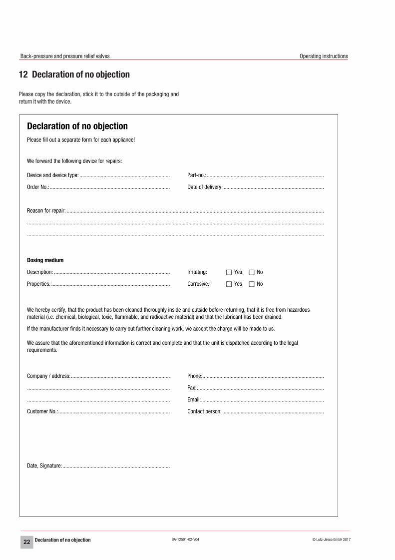
12 Declaration of no objection
Please copy the declaration, stick it to the outside of the packaging and return it with the device.
Declaration of no objectionPlease fill out a separate form for each appliance!
We forward the following device for repairs:
Device and device type: ................................................................ Part-no.:...................................................................................
Order No.: ..................................................................................... Date of delivery: .......................................................................
Reason for repair: ......................................................................................................................................................................................
..................................................................................................................................................................................................................
..................................................................................................................................................................................................................
Dosing medium
Description: .................................................................................. Irritating: Yes No
Properties: .................................................................................... Corrosive: Yes No
We hereby certify, that the product has been cleaned thoroughly inside and outside before returning, that it is free from hazardous material (i.e. chemical, biological, toxic, flammable, and radioactive material) and that the lubricant has been drained.
If the manufacturer finds it necessary to carry out further cleaning work, we accept the charge will be made to us.
We assure that the aforementioned information is correct and complete and that the unit is dispatched according to the legal requirements.
Company / address:...................................................................... Phone:......................................................................................
..................................................................................................... Fax:..........................................................................................
..................................................................................................... Email:.......................................................................................
Customer No.:............................................................................... Contact person: ........................................................................
Date, Signature:............................................................................
Warranty claim 23© Lutz-Jesco GmbH 2017Subject to technical changes.171025
BA-12501-02-V04
Back-pressure and pressure relief valves Operating instructions
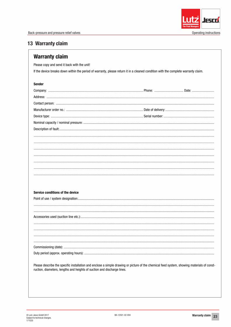
13 Warranty claim
Warranty claimPlease copy and send it back with the unit!
If the device breaks down within the period of warranty, please return it in a cleaned condition with the complete warranty claim.
Sender
Company: ............................................................................................................... Phone: .................................. Date: ..........................
Address: ....................................................................................................................................................................................................
Contact person: .........................................................................................................................................................................................
Manufacturer order no.: .......................................................................................... Date of delivery: .........................................................
Device type: ............................................................................................................ Serial number: ...........................................................
Nominal capacity / nominal pressure: .........................................................................................................................................................
Description of fault:.....................................................................................................................................................................................
...................................................................................................................................................................................................................
...................................................................................................................................................................................................................
...................................................................................................................................................................................................................
...................................................................................................................................................................................................................
...................................................................................................................................................................................................................
...................................................................................................................................................................................................................
...................................................................................................................................................................................................................
Service conditions of the devicePoint of use / system designation:...............................................................................................................................................................
...................................................................................................................................................................................................................
...................................................................................................................................................................................................................
Accessories used (suction line etc.):............................................................................................................................................................
...................................................................................................................................................................................................................
...................................................................................................................................................................................................................
...................................................................................................................................................................................................................
...................................................................................................................................................................................................................
Commissioning (date): ................................................................................................................................................................................
Duty period (approx. operating hours): ........................................................................................................................................................
Please describe the specific installation and enclose a simple drawing or picture of the chemical feed system, showing materials of const-ruction, diameters, lengths and heights of suction and discharge lines.

Recommended