TRAINING MANUALFOR TRAINING PURPOSES ONLY
B767-3S2F ATA 22-00 Page - 1 1/13/14 EFF - ALL
AUTOPILOT FLIGHT DIRECTOR SYSTEMCH 22
TRAINING MANUALFOR TRAINING PURPOSES ONLY
B767-3S2F ATA 22-00 Page - 2 1/13/14 EFF - ALL
ATA 22 AUTOPILOT FLIGHT DIRECTOR SYSTEM
AUTOPILOT FLIGHT DIRECTOR SYSTEM - INTRODUCTION ............4TMS - GENERAL DESCRIPTION ...........................................................8MAINT MONITOR SYSTEM - MCDP AUTO PWR ON MODE..............10FLT CONT/HYD - GENERAL DESCRIPTION ......................................12FLT CONT/HYD - FLIGHT CONTROLS - INTRO .................................14COMPONENT LOCATION - FLIGHT CMPTMNT .................................16FLT CONT/HYD - COMPONENT - HYD SYS CONTROLS ..................18FLT CONT/HYD - COMPONENT - FLT CNTRL INDICATORS ............20FLT CONT/HYD - AILERON CONTROL SYSTEM ...............................22FLT CONT/HYD - ELEVATOR CONTROL SYSTEM ............................24FLT CONT/HYD - RUDDER CONTROL SYSTEM ................................26YSM - YAW DAMPER INTRODUCTION ...............................................28YSM - YAW DAMPER - GENERAL DESCRIPTION .............................30YSM - YAW DAMPER - COMPONENT LOCATION .............................32YSM - GENERAL DESCRIPTION .........................................................34YSM - GENERAL DESCRIPTION - FUNCTIONS .................................36YSM - FAULT RECORDING ................................................................38YSM - BITE ...........................................................................................40YSM - FAULT ANNUNCIATION ............................................................42YSM - YAW DAMPER - PRE FLT TEST FROM FLT DECK .................44YSM - STAB TRIM - INTRODUCTION ..................................................46YSM - STAB TRIM - COMPONENT LOC - FLT DECK .........................48YSM - STAB TRIM - CMPNT LOC - MEC AND JKSCRW AREA ..........50YSM - STAB TRIM - GENERAL DESCRIPTION ..................................52YSM - STAB TRIM - FUNCTIONAL MODE PRIORITY .........................54STAB TRIM SYS - MNL ELEC STAB TRIM - DESCRIPTION .............56STAB TRIM SYS - ALT ELEC STAB TRIM - FCTNL DESC .................58YSM - STAB TRIM - FCTNL DESC - AUTO STAB TRIM... ...................60YSM - STAB TRIM- FAULT ANN - STAB TRIM ....................................62YSM - STAB TRIM - FAULT ANN - UNSCHEDULED TRIM .................70FLT CONT/HYD - GEN DESC - FLIGHTCONTROLS ...........................72AUTOPILOT CONTROL SERVO ..........................................................74 LATERAL CENTRAL CONTROL ACTUATORS .................................76 AFDS GENERAL - AFDS - GENERAL DESCRIPTION .......................78AUTOPILOT FLIGHT DIRECTOR SYSTEM .........................................80AFDS GENERAL - BLOCK DIAGRAM ..................................................82
AFDS GENERAL - COMPONENT LOCATION .....................................84MODE CONTROL PANEL - FUNCTIONS ............................................86AFDS - ANN AND WARN - GEN DESCRIPTION .................................88AFDS GEN - AUTOLAND STATUS ANNUNCIATORS .........................90AFDS - FUNC DESC - ASA - DISPLAY SEQUENCE -1 ........................92AFDS - FUNC DESC - ASA - DISPLAY SEQUENCE - 2 ......................94AFDC - FUNC DESC - ASA - DISPLAY SEQUENCE - 3 ......................96AFDS - FUNC DESC - ASA - DISPLAY SEQUENCE - 4 ......................98MODE CONTROL PANEL INTERNALS .............................................100ENGAGE LOGIC - SIMPLIFIED .........................................................102ENGAGE LOGIC DETAILS - HARDWARE MONITORS .....................104INTERFACE - FCC CROSS-CHANNEL DATA ...................................106AFDS POWER DISTRIBUTION ..........................................................108AFDS FCC POWER DISTRIBUTION .................................................110AUTOLAND POWER SWITCHING - FUNC DESC ............................112AFDS GENERAL - POWER ISOLATION LOGIC ................................116AUTOLAND SEQUENCE ...................................................................118THRUST MANAGEMENT SYSTEM - INTRODUCTION ....................120TMS - COMPONENT LOCATION .......................................................122TMS - THROTTLE COMPONENT LOCATION ...................................124TMS - THRUST MODE SELECT PANEL ...........................................126TMS - OP- EADI DISPLAYS ...............................................................128TMS - OP- ENGINE EICAS DISPLAY - THRUST LIMIT FUNC ..........130TMS - FUNC DESC - SYSTEM BLOCKDIAGRAM ............................132TMS - FUNCTIONAL DESC - SYS BLOCK DIAGRAM CONT. ..........134MAINT FUNCTIONS ...........................................................................136MAINT MONITOR SYSTEM - REMOTE MCDP OPERATION ...........138MAINTENANCE MONITOR SYSTEM - INTERFACE SYSTEMS .......140MAINTENANCE CONTROL AND DISPLAY PANEL ..........................144MAINTENANCE MONITOR SYSTEM - COMP LOC ..........................148 REMOTE MCDP CONTROL PANEL CONNECTOR LOC ................150LRU FAULT CONSOLIDATION ..........................................................152FAULT MESSAGE FORMATS ...........................................................154
TRAINING MANUALFOR TRAINING PURPOSES ONLY
B767-3S2F ATA 22-00 Page - 3 1/13/14 EFF - ALL
STUDENT NOTES:
TRAINING MANUALFOR TRAINING PURPOSES ONLY
B767-3S2F ATA 22-00 Page - 4 1/13/14 EFF - ALL
AUTOPILOT FLIGHT DIRECTOR SYSTEM - INTRODUCTION
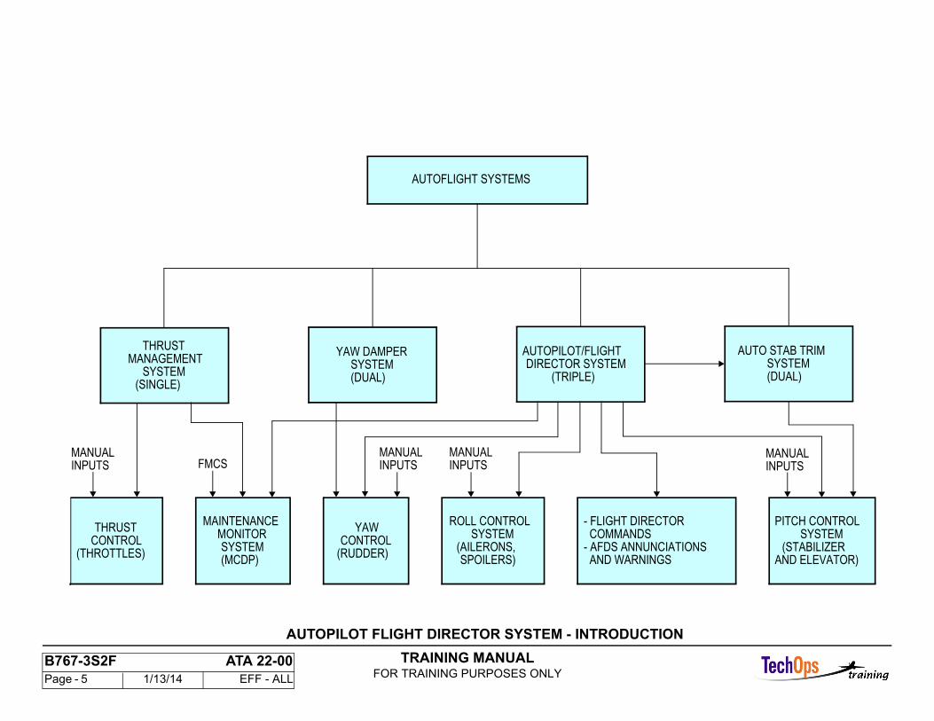
Thrust Management System
The thrust management system has two functions. The system moves the thrust levers and calculates the thrust limit for the EICAS display.
Yaw Damper System
The yaw damper system controls the rudder to decrease yaw oscillations because of a Dutch roll or gustinduced sideslips.
Automatic Stabilizer Trim and Mach Trim System
The automatic stabilizer trim and Mach trim system controls stabilizer position as a function of these:
- Mach at high speeds- Autopilot trim commands with the autopilot engaged.
Autopilot Flight Director System
The autopilot flight director system gives automatic control for these control systems to operate the selected mode:
- Aileron- Elevator- Stabilizer- Rudder.
The autopilot flight director system also gives pitch and roll flight director commands, system warnings, and annunciations.
Maintenance Monitor System
The maintenance monitor system gives a centralized flight and ground faults readout and ground test function for these systems:
- Autopilot flight director system- Thrust management system- Flight management system.
TRAINING MANUALFOR TRAINING PURPOSES ONLY
B767-3S2F ATA 22-00 Page - 5 1/13/14 EFF - ALL
AUTOFLIGHT SYSTEMS
THRUSTMANAGEMENT
SYSTEM(SINGLE)
MANUALINPUTS
THRUSTCONTROL
(THROTTLES)
FMCS
MAINTENANCEMONITORSYSTEM(MCDP)
YAW DAMPER
MANUALINPUTS
YAWCONTROL
(RUDDER)
MANUALINPUTS
AUTOPILOT/FLIGHTDIRECTOR SYSTEM
(TRIPLE)
ROLL CONTROLSYSTEM
(AILERONS,SPOILERS)
- FLIGHT DIRECTOR COMMANDS- AFDS ANNUNCIATIONS AND WARNINGS
PITCH CONTROLSYSTEM
MANUALINPUTS
(STABILIZER
AUTO STAB TRIM
AND ELEVATOR)
SYSTEM(DUAL)
SYSTEM(DUAL)
AUTOPILOT FLIGHT DIRECTOR SYSTEM - INTRODUCTION
TRAINING MANUALFOR TRAINING PURPOSES ONLY
B767-3S2F ATA 22-00 Page - 6 1/13/14 EFF - ALL
AUTOPILOT FLIGHT DIRECTOR SYSTEM - INTRODUCTION
General
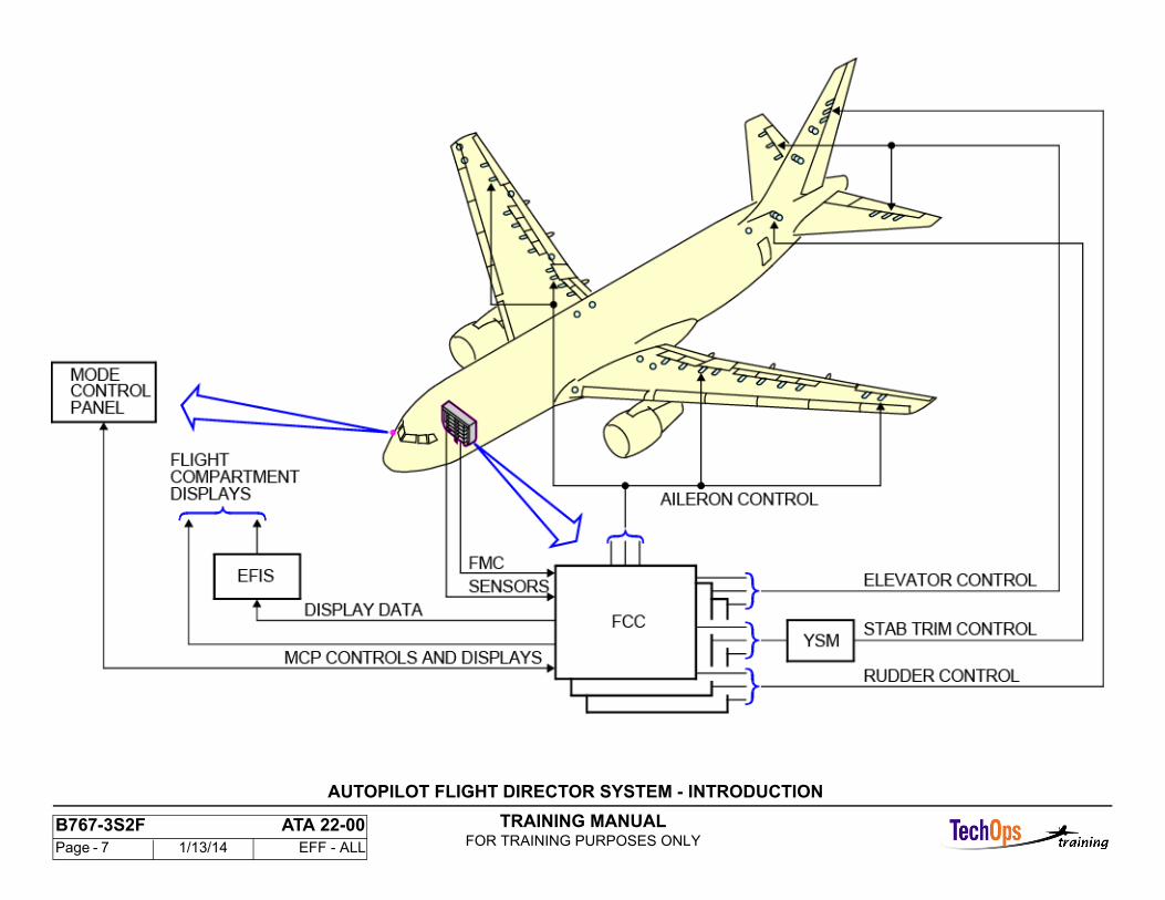
The autopilot flight director system (AFDS) is a triple-channel system which operates as a single channel system for cruise. For cruise, the AFDS controls the pitch and roll axes of the airplane and gives pitch and roll flight director commands. For approach, land, rollout, and go-around, the AFDS operates as a multi-channel (dual or triple) system to control the pitch, roll, and yaw axes of the airplane.
TRAINING MANUALFOR TRAINING PURPOSES ONLY
B767-3S2F ATA 22-00 Page - 7 1/13/14 EFF - ALL
AUTOPILOT FLIGHT DIRECTOR SYSTEM - INTRODUCTION
TRAINING MANUALFOR TRAINING PURPOSES ONLY
B767-3S2F ATA 22-00 Page - 8 1/13/14 EFF - ALL
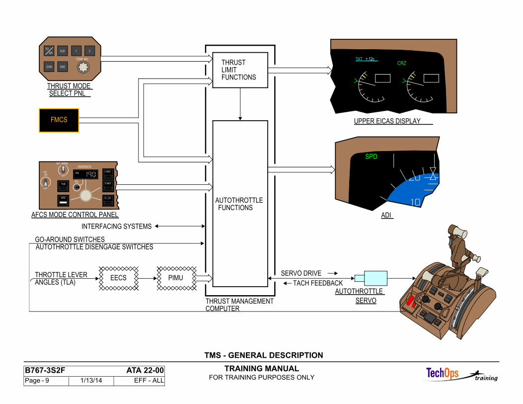
TMS - GENERAL DESCRIPTION
Purpose
The thrust management computer (TMC) has a thrust limit function and an autothrottle function. These functions each have different modes that you select and show in different locations.
Thrust Limit Functions
Selection of the thrust limit modes are from the thrust mode select panel (TMSP) or by the FMC in VNAV mode. They show on EICAS.
The thrust limit functions are always active. The thrust limit shows on EICAS and is an upper limit for autothrottle calculations.
Autothrottle Functions
Selection of the autothrottle modes are from the AFCS mode control panel(MCP) or by the FMC in VNAV mode. They show on the EADI.
The autothrottle engages in a mode when the AFCS MCP switch is in the A/T ARM position, and you select a mode. These functions move the thrust levers.
The propulsion interface management unit (PIMU) is a digital buffer between the electronic engine control (EEC) and the TMC.
TRAINING MANUALFOR TRAINING PURPOSES ONLY
B767-3S2F ATA 22-00 Page - 9 1/13/14 EFF - ALL
+ 12cTAT
ADI
SPD
UPPER EICAS DISPLAY
CRZ
THRUST MANAGEMENTCOMPUTER
THROTTLE LEVERANGLES (TLA)
EECS
AUTOTHROTTLE DISENGAGE SWITCHESGO-AROUND SWITCHES
INTERFACING SYSTEMS
SERVO
AUTOTHROTTLETACH FEEDBACK
SERVO DRIVE
FMCS
PIMU
AFCS MODE CONTROL PANEL
IAS
IAS/MACH
FL CH
V NAV
L NAV
SEL
OFF
A/T ARM
SPD
OFF
F/DON
THR
2
CON
THRUST MODE
CLB 1
TEMP SEL
CRZ
GA
TO
SELECT PNL
FMCS
THRUST
AUTOTHROTTLEFUNCTIONS
LIMITFUNCTIONS
TMS - GENERAL DESCRIPTION
TRAINING MANUALFOR TRAINING PURPOSES ONLY
B767-3S2F ATA 22-00 Page - 10 1/13/14 EFF - ALL
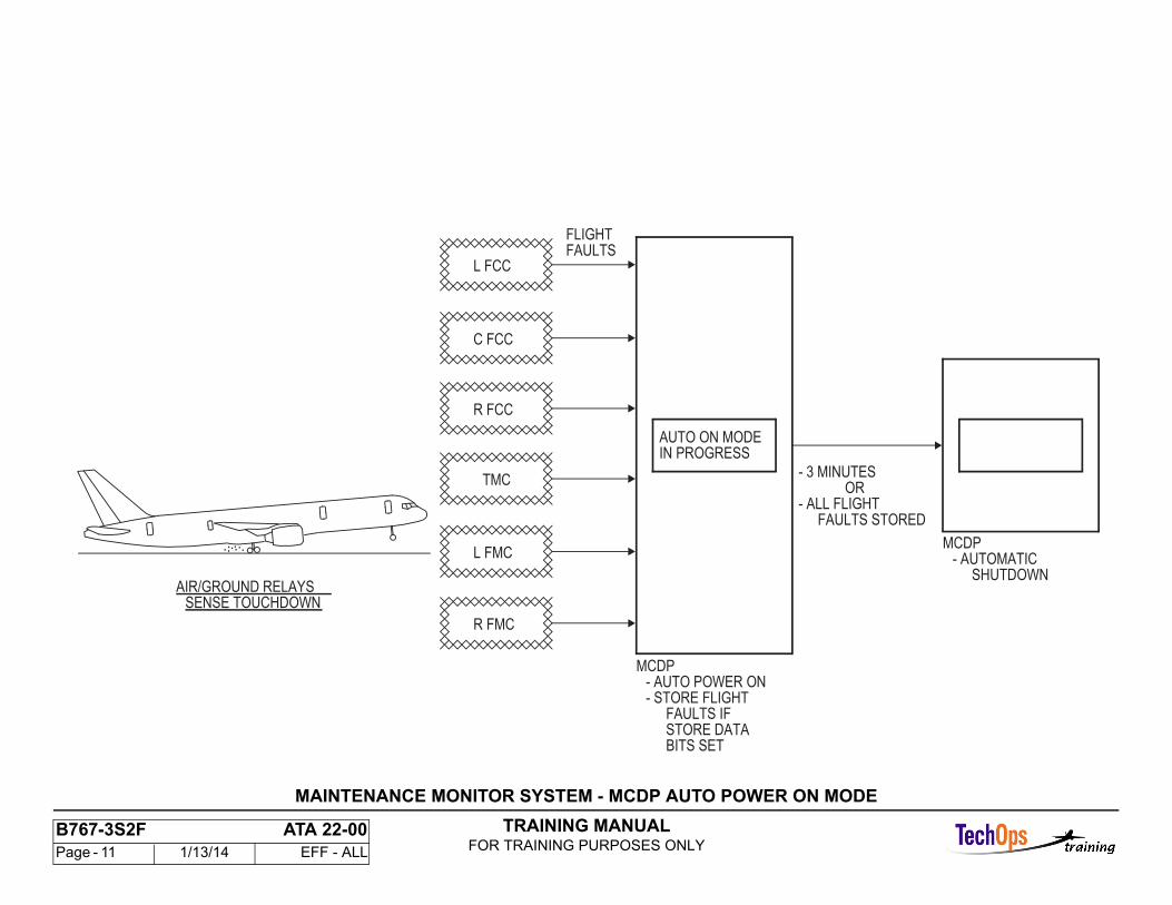
MAINTENANCE MONITOR SYSTEM - MCDP AUTO POWER ON MODE
Initiation
The MCDP comes on when either air/ground input changes from an in-air to an on-ground state. This normally occurs at touchdown in order to store last flightfaults.
The STORE DATA Bit is sent by the computers only when this sequence of events has occurred:
- IRS ground speed 100 Kts and air/ground = in air- IRS ground speed 40 Kts and air ground = on ground- For the FCCs, the autopilot channel is disengaged.
Termination
The auto power on mode will stop when last flight fault data has been received from all computers with their store data bits set on, or after three minutes. During the auto power ON mode, the MCDP switches are deactivated.
Undesired Power-Up
Auto power-up will also occur if the air-ground circuit breakers, LDG GR POSITION AIR/GND SYS 1 and POSITION AIR/GND SYS 2, are cycled from off to on because this sends a transition from in-air to on-ground to theMCDP. Air/ground inputs may also cycle during power transfer of external/generator/APU power. You may stop the three-minute auto power-up period, if caused by ground operation of the air/ground circuit breakers or power transfer by a cycle of the MAINT CONT DISPLAY circuit breaker.
Message Displayed
During this auto power-on mode, the display message is AUTO ON MODE IN PROGRESS.
Faults Not Stored
Self-tests are DONE during the auto on mode. Any selftest failure will cause the MCDP to shut down. Failure data for this condition is not stored. Failures willshow when you do a manual power-up.
TRAINING MANUALFOR TRAINING PURPOSES ONLY
B767-3S2F ATA 22-00 Page - 11 1/13/14 EFF - ALL
- 3 MINUTES
- ALL FLIGHTFAULTS STORED
MCDP- AUTO POWER ON- STORE FLIGHT
FAULTS IFSTORE DATABITS SET
MCDP- AUTOMATIC
SHUTDOWN
........
SENSE TOUCHDOWNAIR/GROUND RELAYS
L FCC
C FCC
R FCC
TMC
L FMC
R FMC
AUTO ON MODEIN PROGRESS
FLIGHTFAULTS
OR
MAINTENANCE MONITOR SYSTEM - MCDP AUTO POWER ON MODE
TRAINING MANUALFOR TRAINING PURPOSES ONLY
B767-3S2F ATA 22-00 Page - 12 1/13/14 EFF - ALL
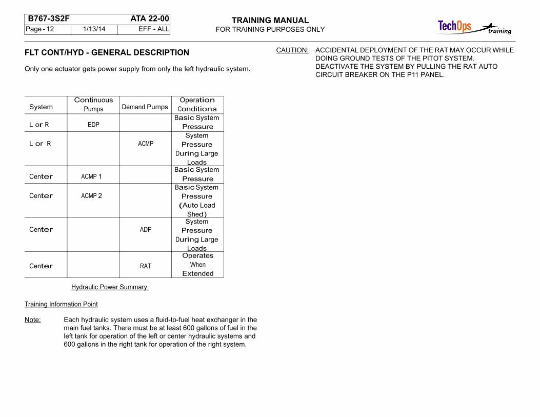
FLT CONT/HYD - GENERAL DESCRIPTION
Only one actuator gets power supply from only the left hydraulic system.
SystemContinuous
Pumps Demand PumpsOperation
Conditions
L or R EDPBasic System
Pressure
L or R ACMPSystem
Pressure During Large
Loads
Center ACMP 1Basic System
Pressure
Center ACMP 2Basic System
Pressure (Auto Load
Shed)
Center ADPSystem
Pressure During Large
Loads
Center RAT
Operates When
Extended
Hydraulic Power Summary
Training Information Point
Note: Each hydraulic system uses a fluid-to-fuel heat exchanger in the main fuel tanks. There must be at least 600 gallons of fuel in the left tank for operation of the left or center hydraulic systems and 600 gallons in the right tank for operation of the right system.
CAUTION: ACCIDENTAL DEPLOYMENT OF THE RAT MAY OCCUR WHILE DOING GROUND TESTS OF THE PITOT SYSTEM. DEACTIVATE THE SYSTEM BY PULLING THE RAT AUTO CIRCUIT BREAKER ON THE P11 PANEL.
TRAINING MANUALFOR TRAINING PURPOSES ONLY
B767-3S2F ATA 22-00 Page - 13 1/13/14 EFF - ALL
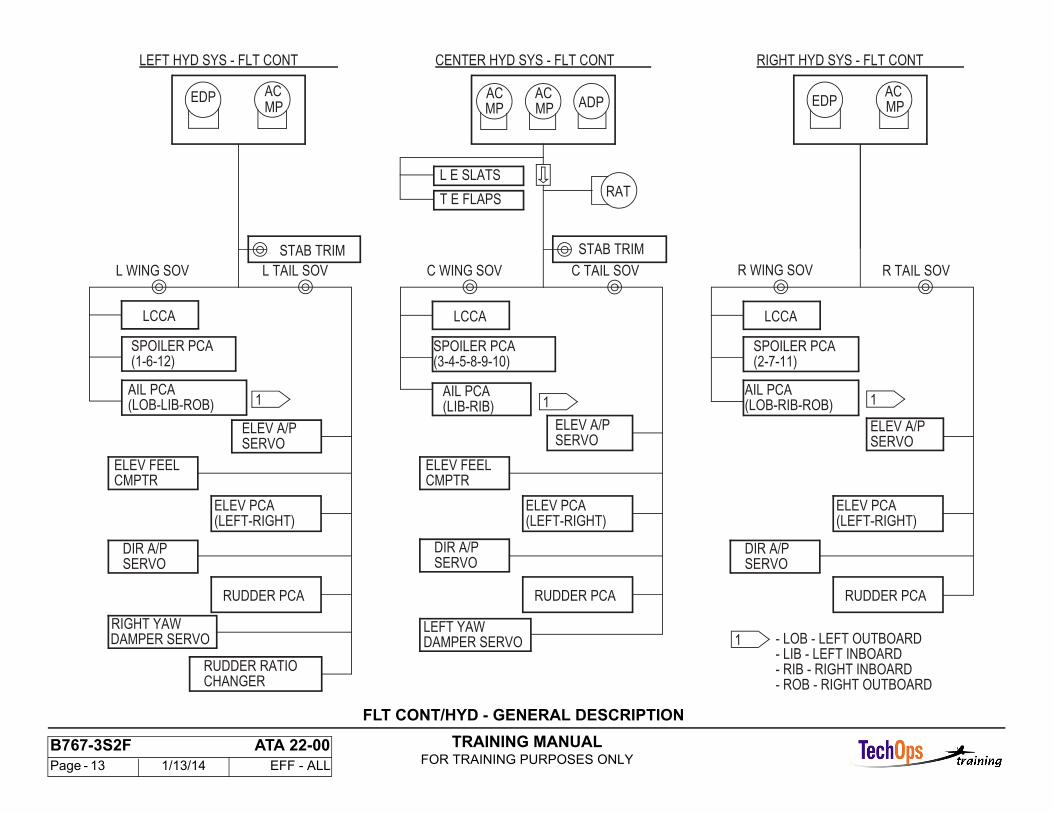
STAB TRIM STAB TRIM
CHANGERRUDDER RATIO
DAMPER SERVOLEFT YAW
RUDDER PCA
SERVO
(1-6-12)
(LOB-LIB-ROB)
LCCA
ELEV A/P
AIL PCA
SPOILER PCA
L WING SOV L TAIL SOV
(LEFT-RIGHT)
(LIB-RIB)
(3-4-5-8-9-10)
SERVOELEV A/P
DIR A/PSERVO
ELEV FEELCMPTR
LCCA
C TAIL SOV
ELEV PCA
AIL PCA
SPOILER PCA
C WING SOV
(LOB-RIB-ROB)
(2-7-11)
SERVOELEV A/P
LCCA
R TAIL SOV
AIL PCA
SPOILER PCA
R WING SOV
RAT
ACEDPADP
ACACACEDP
RIGHT HYD SYS - FLT CONT
L E SLATS
T E FLAPS
CENTER HYD SYS - FLT CONTLEFT HYD SYS - FLT CONT
- ROB - RIGHT OUTBOARD- RIB - RIGHT INBOARD- LIB - LEFT INBOARD- LOB - LEFT OUTBOARD
MP MP MP MP
1 11
1DAMPER SERVORIGHT YAW
RUDDER PCA
(LEFT-RIGHT)
DIR A/PSERVO
ELEV FEELCMPTR
ELEV PCA
RUDDER PCA
(LEFT-RIGHT)
DIR A/PSERVO
ELEV PCA
FLT CONT/HYD - GENERAL DESCRIPTION
TRAINING MANUALFOR TRAINING PURPOSES ONLY
B767-3S2F ATA 22-00 Page - 14 1/13/14 EFF - ALL
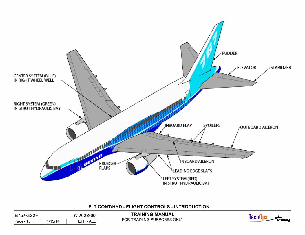
FLT CONT/HYD - FLIGHT CONTROLS - INTRODUCTION
Purpose
The flight control system controls the airplane attitude as necessary to follow a flight profile.
Flight Control System Description
The flight control system includes primary controls which directly control airplane attitude and secondary controls which change the effectiveness of primary controls.
These are the primary controls:
- Two inboard and two outboard aileron surfaces provide roll or lateral control- Two elevator surfaces provide primary pitch control- One rudder surface provides yaw control.
These are the secondary flight controls:
- Twelve spoiler segments help roll control and effect lift and drag- The moveable horizontal stabilizer helps pitch control- Twelve leading edge slats and four trailing edge flaps are high lift devices which change the effectiveness of the primary control surfaces.
TRAINING MANUALFOR TRAINING PURPOSES ONLY
B767-3S2F ATA 22-00 Page - 15 1/13/14 EFF - ALL
FLT CONT/HYD - FLIGHT CONTROLS - INTRODUCTION
TRAINING MANUALFOR TRAINING PURPOSES ONLY
B767-3S2F ATA 22-00 Page - 16 1/13/14 EFF - ALL
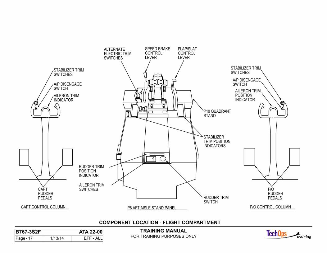
COMPONENT LOCATION - FLIGHT COMPARTMENT
Primary Flight Control Inputs
Manual inputs for pitch, roll, and yaw control are provided by the captain andfirst officer control column, control wheel, and rudder pedals. The control wheelshave switches to disengage the autopilot.
Aileron trim control is provided by two switches on the P8 aft aisle stand panel.The trim position indicators are on top of the control wheels.
The rudder trim switch is a round knob to the right of the aileron trim switches.The rudder trim position indicator is forward of the trim switch
Secondary Flight Control Inputs
Stabilizer trim control can be done either electrically with the thumb switches onthe outboard horn of each control wheel or with either alternate electric
stabilizer trim arm and control switches or via manual arm and control levers onthe P10 quadrant stand. The stabilizer trim is the only method for pitch trim.
There is no elevator trim. The manual flap / slat control lever and speed brakecontrol lever are also on the P10 quadrant stand.
TRAINING MANUALFOR TRAINING PURPOSES ONLY
B767-3S2F ATA 22-00 Page - 17 1/13/14 EFF - ALL
ELECTRIC TRIMSWITCHES
ALTERNATE
A/P DISENGAGE
STABILIZER TRIM
CAPT
PEDALSRUDDER
INDICATORAILERON TRIM
INDICATORPOSITIONRUDDER TRIM
INDICATORSTRIM POSITIONSTABILIZER
STANDP10 QUADRANT
SWITCH
POSITIONAILERON TRIM
PEDALSRUDDERF/O
STABILIZER TRIM
FLAP/SLATCONTROLLEVER
CONTROLSPEED BRAKE
CAPT CONTROL COLUMN F/O CONTROL COLUMNP8 AFT AISLE STAND PANEL
A/P DISENGAGESWITCH
SWITCHESSWITCHES
SWITCHRUDDER TRIM
SWITCHESAILERON TRIM
INDICATOR
LEVER
COMPONENT LOCATION - FLIGHT COMPARTMENT
TRAINING MANUALFOR TRAINING PURPOSES ONLY
B767-3S2F ATA 22-00 Page - 18 1/13/14 EFF - ALL
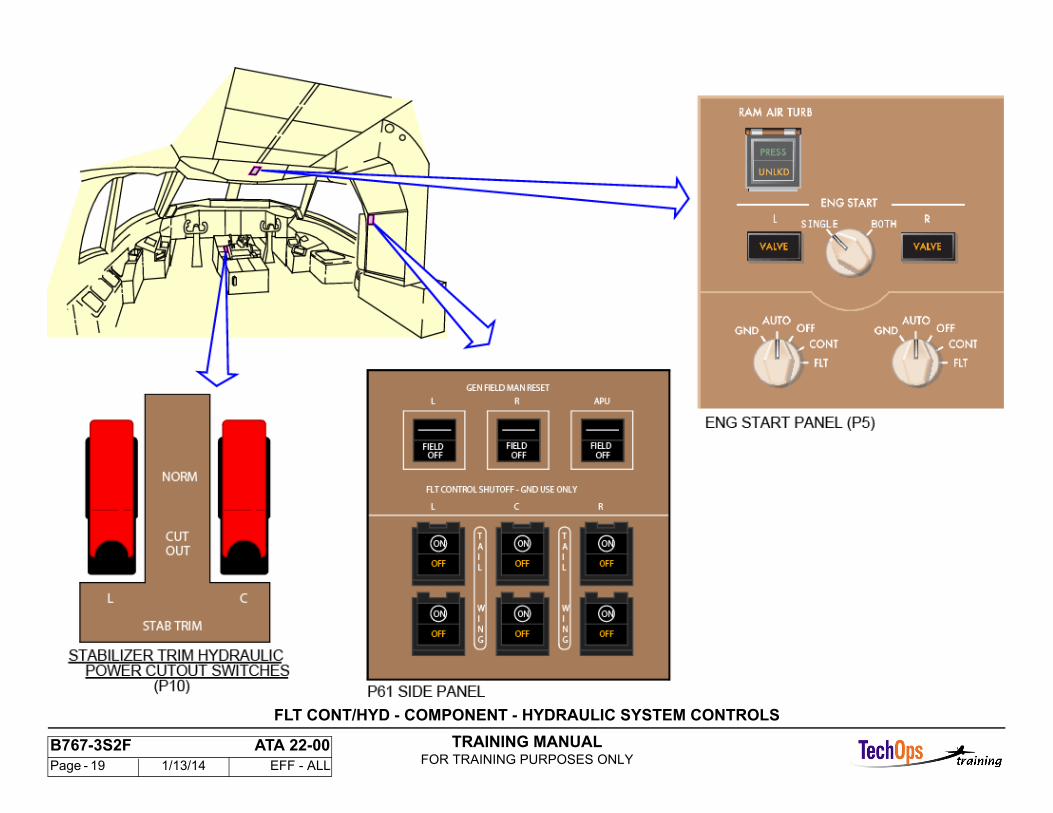
FLT CONT/HYD - COMPONENT - HYDRAULIC SYSTEMCONTROLS
Engine Ignition and Start Control Panel
The switch for manual deployment of the ram air turbine (RAT) is on this panel. You push the switch to extend the RAT. The lower part of the switch (UNLOCKD) comes on amber to show that the extend mechanism releases.Electric power connects to a motor to extend the turbine. The upper part of the switch (PRESS) comes on in green when the RAT extends, and the pressure gets to 1275 psi.
You cannot retract the RAT in the air. You must manually put the blades to center for retraction on the ground.
Stabilizer Trim Hydraulics Power Cutout Switches
The stabilizer trim hydraulic power cutout switches individually control left and center hydraulic pressure to the stabilizer trim control modules. The switchesare on the P10 control stand.
Hydraulic Flight Control Panel
The hydraulic flight control panel has controls that isolate hydraulic systems for troubleshooting. Push-on/push-off switches on the hydraulic flightcontrol panel individually operate hydraulic system shutoff valves (SOVs). Shutters in the switch are a cover for or show the word ON in the upper part of the switch. The word OFF comes on in amber when the SOV is off.
Wing SOVs control pressure to the wing actuators and servos for ailerons and spoilers.
Tail SOVs control pressure to elevator and rudder components.
TRAINING MANUALFOR TRAINING PURPOSES ONLY
B767-3S2F ATA 22-00 Page - 19 1/13/14 EFF - ALL
FLT CONT/HYD - COMPONENT - HYDRAULIC SYSTEM CONTROLS
TRAINING MANUALFOR TRAINING PURPOSES ONLY
B767-3S2F ATA 22-00 Page - 20 1/13/14 EFF - ALL
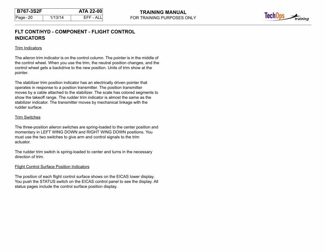
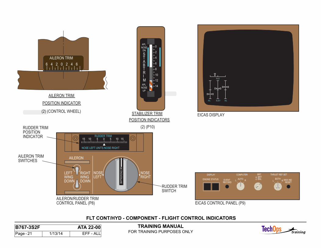
FLT CONT/HYD - COMPONENT - FLIGHT CONTROL INDICATORS
Trim Indicators
The aileron trim indicator is on the control column. The pointer is in the middle of the control wheel. When you use the trim, the neutral position changes, and thecontrol wheel gets a backdrive to the new position. Units of trim show at the pointer.
The stabilizer trim position indicator has an electrically driven pointer that operates in response to a position transmitter. The position transmittermoves by a cable attached to the stabilizer. The scale has colored segments to show the takeoff range. The rudder trim indicator is almost the same as thestabilizer indicator. The transmitter moves by mechanical linkage with the rudder surface.
Trim Switches
The three-position aileron switches are spring-loaded to the center position and momentary in LEFT WING DOWN and RIGHT WING DOWN positions. You must use the two switches to give arm and control signals to the trimactuator.
The rudder trim switch is spring-loaded to center and turns in the necessary direction of trim.
Flight Control Surface Position Indicators
The position of each flight control surface shows on the EICAS lower display. You push the STATUS switch on the EICAS control panel to see the display. All status pages include the control surface position display.
TRAINING MANUALFOR TRAINING PURPOSES ONLY
B767-3S2F ATA 22-00 Page - 21 1/13/14 EFF - ALL
05RUDDER TRIM
NOSE LEFT UNITS NOSE RIGHT
15 10 15105
RUDDER TRIM
RUDDER TRIM
AILERON TRIM
AILERON TRIM
POSITION INDICATOR
DISPLAY
ENGINE STATUS
COMPUTER
LAUTO
R
BRT
LBOTH
R MAX IND RESET
BRT
EVENTRECORD
BAL
THRUST REF SET
EICAS CONTROL PANEL (P9)
AILERON
LEFTWINGDOWN
NOSELEFT
RIGHTWINGDOWN
NOSERIGHT
AILERON/RUDDER TRIMCONTROL PANEL (P8)
INDICATORPOSITION
SWITCHES
SWITCH
STABILIZER TRIM
POSITION INDICATORS
(2) (P10)
AILELEVAIL
RUD
EICAS DISPLAY
ST
MIRTBA
NOSE
APL
DN
UP
NOSEAPL
10
2
FFO
14
12
8
6
4
0
AILERON TRIM
6 4 2 0 2 4 6
(2) (CONTROL WHEEL)(2) (
FLT CONT/HYD - COMPONENT - FLIGHT CONTROL INDICATORS
TRAINING MANUALFOR TRAINING PURPOSES ONLY
B767-3S2F ATA 22-00 Page - 22 1/13/14 EFF - ALL
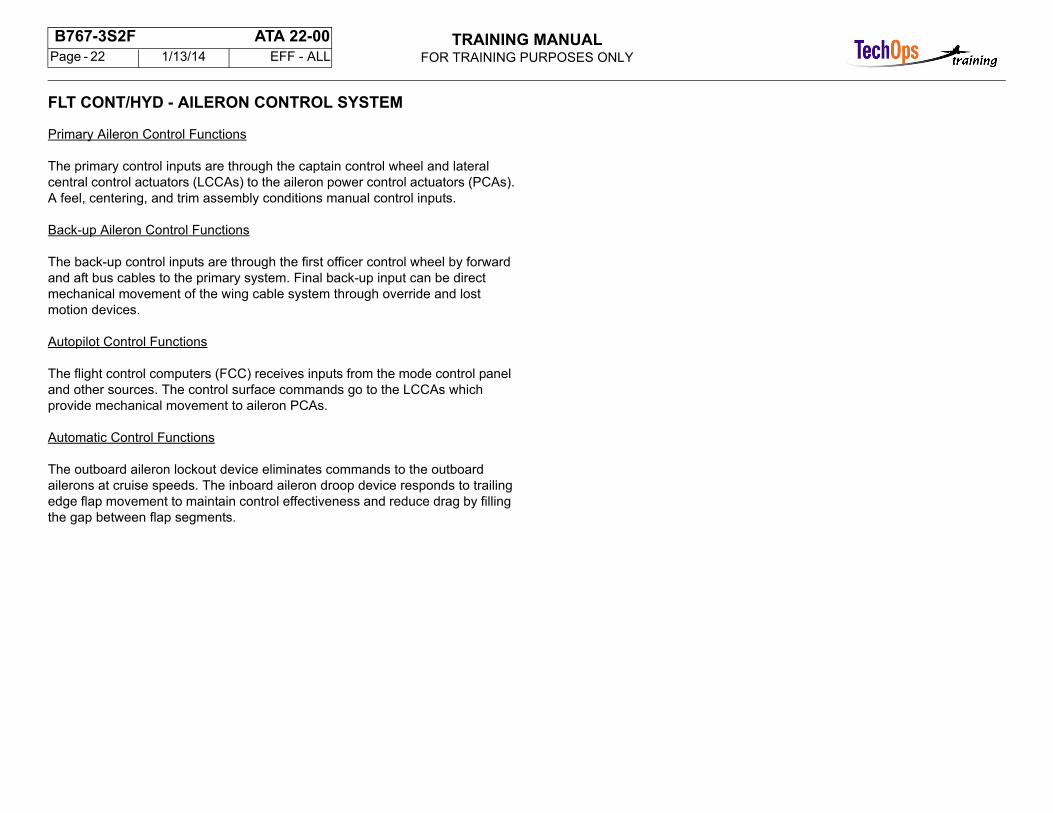
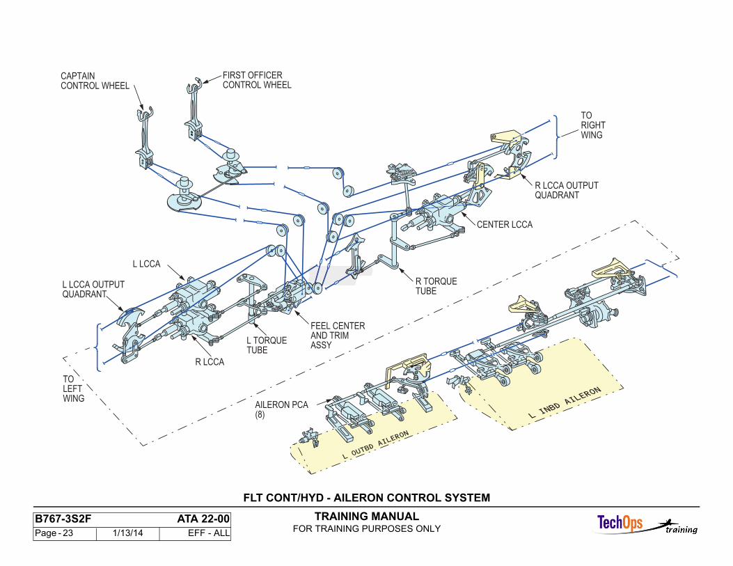
FLT CONT/HYD - AILERON CONTROL SYSTEM
Primary Aileron Control Functions
The primary control inputs are through the captain control wheel and lateral central control actuators (LCCAs) to the aileron power control actuators (PCAs).A feel, centering, and trim assembly conditions manual control inputs.
Back-up Aileron Control Functions
The back-up control inputs are through the first officer control wheel by forward and aft bus cables to the primary system. Final back-up input can be directmechanical movement of the wing cable system through override and lost motion devices.
Autopilot Control Functions
The flight control computers (FCC) receives inputs from the mode control panel and other sources. The control surface commands go to the LCCAs which provide mechanical movement to aileron PCAs.
Automatic Control Functions
The outboard aileron lockout device eliminates commands to the outboard ailerons at cruise speeds. The inboard aileron droop device responds to trailingedge flap movement to maintain control effectiveness and reduce drag by filling the gap between flap segments.
TRAINING MANUALFOR TRAINING PURPOSES ONLY
B767-3S2F ATA 22-00 Page - 23 1/13/14 EFF - ALL
L LCCA
R LCCA
L TORQUETUBE
FEEL CENTERAND TRIM
R TORQUETUBE
CENTER LCCA
R LCCA OUTPUTQUADRANT
L LCCA OUTPUTQUADRANT
ASSY
AILERON PCA(8)
CAPTAINCONTROL WHEEL
FIRST OFFICERCONTROL WHEEL
TORIGHTWING
TOLEFTWING
FLT CONT/HYD - AILERON CONTROL SYSTEM
TRAINING MANUALFOR TRAINING PURPOSES ONLY
B767-3S2F ATA 22-00 Page - 24 1/13/14 EFF - ALL
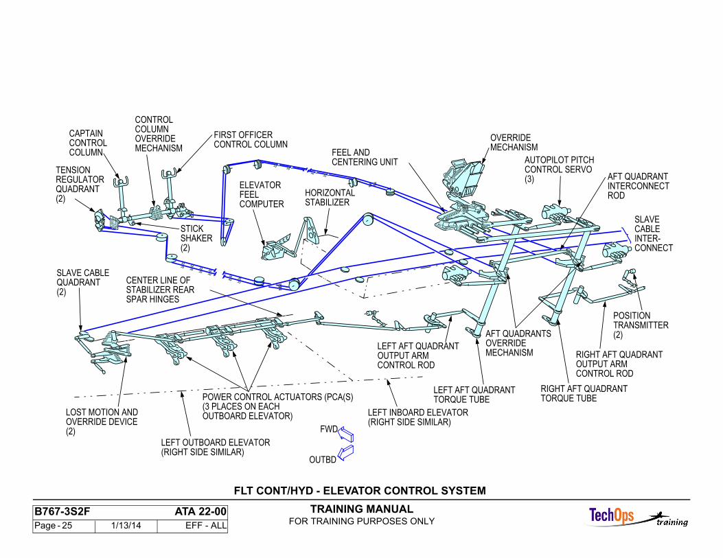
FLT CONT/HYD - ELEVATOR CONTROL SYSTEM
Control Inputs
Manual pitch attitude control inputs can be from either control column by a separate cable system to the aft quadrant aft of the horizontal stabilizer. The two are interconnected by a torque tube at the control columns and by linkage at the aft quadrant. There is no power boost for manual inputs.
Autopilot input is from three flight control computers (FCC) to three servos. The servos move the aft quadrant torque tubes. The servos have LVDTs which provide autopilot actuator position and output position to the FCCs.
Control Conditioning
Manual inputs are conditioned by the feel unit which obtains data from the feel computers. Feel pressure changes with airspeed and stabilizer position. The feel unit also has a centering mechanism to maintain a neutral position when there is no input.
Control Outputs
Elevator control movements go to the left and right power control actuators (PCA) by mechanical linkage. There is an interconnection between elevator PCA linkages by slave cable to prevent a large asymmetry. Position transmitters are at each elevator to provide control surface position on the EICAS display.
TRAINING MANUALFOR TRAINING PURPOSES ONLY
B767-3S2F ATA 22-00 Page - 25 1/13/14 EFF - ALL
STICK
MECHANISMOVERRIDE
CENTERING UNITFEEL AND
(2)OVERRIDE DEVICELOST MOTION AND
ELEVATORFEEL
TORQUE TUBERIGHT AFT QUADRANT
TORQUE TUBELEFT AFT QUADRANT
ROD
AFT QUADRANTINTERCONNECT
AFT QUADRANTSOVERRIDE MECHANISM RIGHT AFT QUADRANT
OUTPUT ARM
TRANSMITTER(2)
POSITION
SLAVE
INTER-
AUTOPILOT PITCHCONTROL SERVO(3)
OUTPUT ARM CONTROL ROD
LEFT AFT QUADRANT
(RIGHT SIDE SIMILAR)LEFT INBOARD ELEVATOR
POWER CONTROL ACTUATORS (PCA(S)(3 PLACES ON EACH
LEFT OUTBOARD ELEVATOR(RIGHT SIDE SIMILAR)
HORIZONTALSTABILIZERCOMPUTER
CENTER LINE OFSTABILIZER REARSPAR HINGES
SLAVE CABLEQUADRANT(2)
(2)
MECHANISMOVERRIDE
CONTROL COLUMN
CONTROLCAPTAIN
TENSIONREGULATORQUADRANT(2)
COLUMN
SHAKER
CONTROL ROD
OUTBOARD ELEVATOR)
CONNECT
CABLE
FIRST OFFICERCONTROL COLUMN
FWD
OUTBD
FLT CONT/HYD - ELEVATOR CONTROL SYSTEM
TRAINING MANUALFOR TRAINING PURPOSES ONLY
B767-3S2F ATA 22-00 Page - 26 1/13/14 EFF - ALL
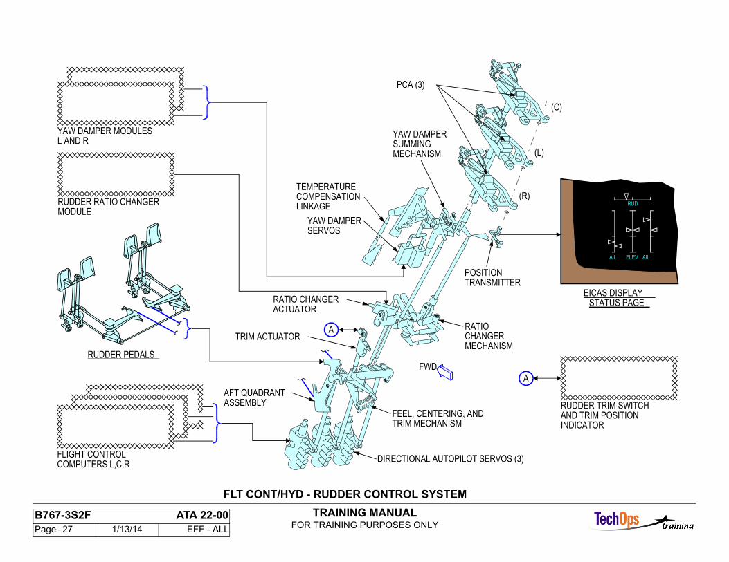
FLT CONT/HYD - RUDDER CONTROL SYSTEM
Rudder System Description
Rudder system components are in different locations. Rudder pedals, the trim switch, and indicator are in the flight compartment. System electronics are in the main equipment center. These components are in the vertical stabilizer:
- Autopilot rollout guidance servos- Aft quadrant with the trim feel and centering unit- Ratio changer mechanism- Yaw damper actuators- Power control actuators (PCAs).
The position transmitter on the rudder gives position data for the EICAS display.
Rudder System Function
Manual rudder inputs are mechanical to the PCA control lever. These components have an effect on the input:
- Feel, centering, and trim mechanism- Ratio changer- Yaw damper.
Autopilot inputs from the flight control computers give directional guidance only during a multichannel approach and rollout.
The YSMs use airspeed and yaw rate from the ADIRU to give turn coordination and decrease unwanted yaw. The rudder ratio module controls the ratio of rudder input to rudder movement through the ratio changer. The schedule of rudder ratio as a function of airspeed is from the yaw damper/stabilizer trim module (YSM). All inputs move the PCA control levers to control rudder movement. Each PCA gets power from a different hydraulic system.
Trim
Trim inputs from the flight compartment control switch move the aft quadrant assembly and give a maximum rudder movement of 16.8 degrees. Trim operation does a backdrive of the cables and rudder pedals.
Power Control Actuators (PCA)
Three PCAs move the rudder each with a different hydraulic system. The left hydraulic system pressure to the middle PCA goes through the ratio changer actuator. If the ratio changer function has a failure, the middle PCA depressurizes. Each PCA has an override in the input linkage to its control valve.
TRAINING MANUALFOR TRAINING PURPOSES ONLY
B767-3S2F ATA 22-00 Page - 27 1/13/14 EFF - ALL
ASSEMBLYAFT QUADRANT
FEEL, CENTERING, AND
RATIO
MECHANISMCHANGER
POSITIONTRANSMITTER
TEMPERATURECOMPENSATIONLINKAGE
YAW DAMPER
MECHANISMSUMMING
PCA (3)
(C)
(L)
(R)
YAW DAMPERSERVOS
TRIM ACTUATOR
EICAS DISPLAY
AIL AILELEV
RUD
FLIGHT CONTROL COMPUTERS L,C,R
YAW DAMPER MODULESL AND R
RUDDER RATIO CHANGERMODULE
TRIM MECHANISM
DIRECTIONAL AUTOPILOT SERVOS (3)
RATIO CHANGER
RUDDER PEDALS
RUDDER TRIM SWITCHAND TRIM POSITIONINDICATOR
ACTUATORSTATUS PAGE
A
A
FWD
FLT CONT/HYD - RUDDER CONTROL SYSTEM
TRAINING MANUALFOR TRAINING PURPOSES ONLY
B767-3S2F ATA 22-00 Page - 28 1/13/14 EFF - ALL
YSM - YAW DAMPER INTRODUCTION
Dutch Roll
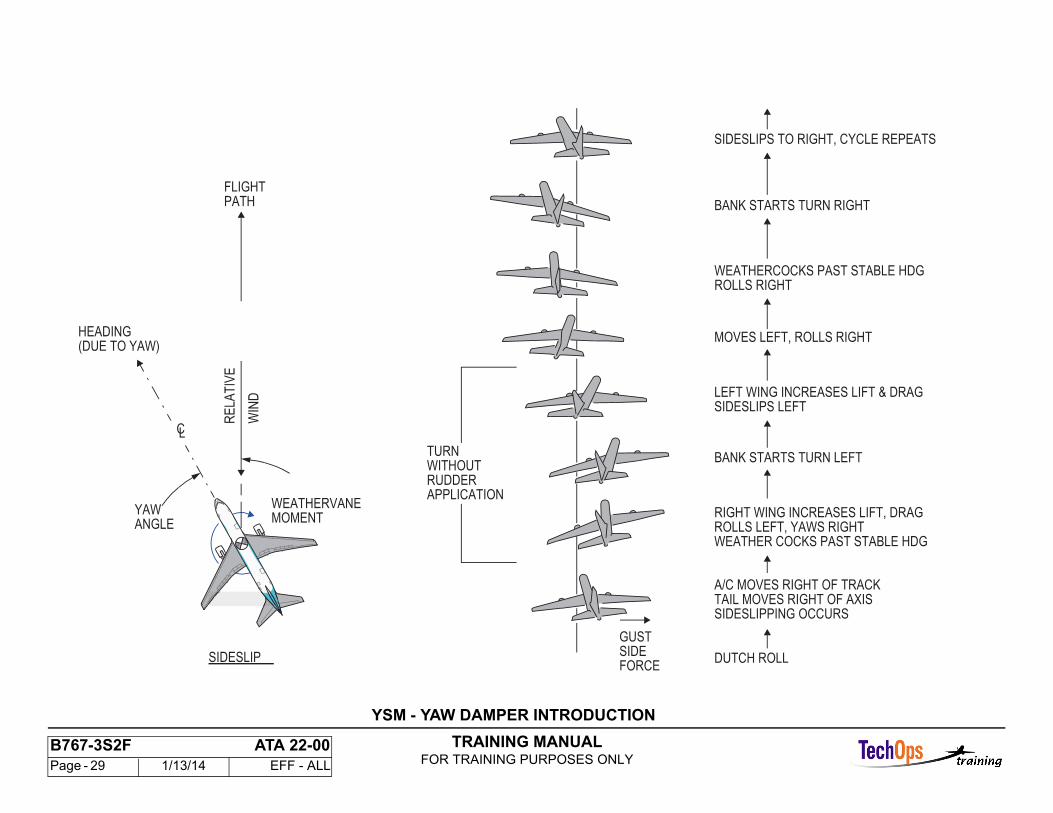
Dutch Roll is a common oscillatory condition caused by low-drag, high-speed aerodynamic design and turbulence that is created by air mass instability.The yaw damper system gives damping with the rudder to decrease dutch roll by the measurement of lateral acceleration and yaw rate.
Turn Coordination
The yaw damper system gives additional rudder commands to prevent yaw when the airplane rolls into a turn. The roll induced yaw is opposite to the intended turn direction. Rudder deflection is necessary to have a coordinated turn.
TRAINING MANUALFOR TRAINING PURPOSES ONLY
B767-3S2F ATA 22-00 Page - 29 1/13/14 EFF - ALL
FLIGHTPATH
HEADING(DUE TO YAW)
CL
MOMENT
SIDESLIP
TURNWITHOUTRUDDERAPPLICATION
RE
LAT
IVE
WIN
D
SIDESLIPS TO RIGHT, CYCLE REPEATS
BANK STARTS TURN RIGHT
MOVES LEFT, ROLLS RIGHT
BANK STARTS TURN LEFT
RIGHT WING INCREASES LIFT, DRAG
DUTCH ROLL
WEATHERCOCKS PAST STABLE HDGROLLS RIGHT
ANGLE ROLLS LEFT, YAWS RIGHT WEATHER COCKS PAST STABLE HDG
A/C MOVES RIGHT OF TRACKTAIL MOVES RIGHT OF AXISSIDESLIPPING OCCURS
GUSTSIDEFORCE
LEFT WING INCREASES LIFT & DRAG SIDESLIPS LEFT
YAW WEATHERVANE
YSM - YAW DAMPER INTRODUCTION
TRAINING MANUALFOR TRAINING PURPOSES ONLY
B767-3S2F ATA 22-00 Page - 30 1/13/14 EFF - ALL
YSM - YAW DAMPER - GENERAL DESCRIPTION
General
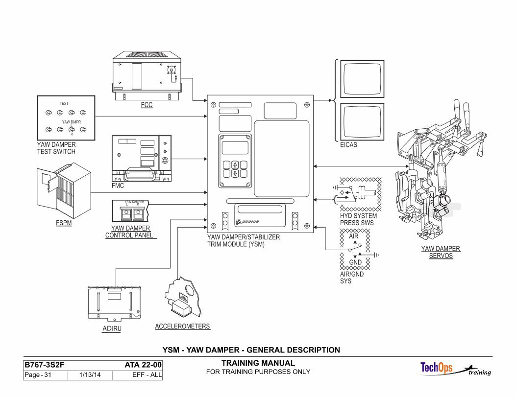
The yaw damper system has two self-monitored, limited rudder authority yaw damper functions that operate independently. They are the same. Each yaw damper function gives a maximum of plus or minus three degrees of rudder authority. To move the rudder, the output from the yaw damper function of thetwo YSMs mechanically add together and then add in series with pilot or autopilot commands. The two yaw damper outputs add for a maximum of plus or minus six degrees of rudder authority.
Major Components
The yaw damper system has these major components:
- Yaw damper control panel - flight crew control of system engagement- Left and right YSMs - control law calculation and system fault monitor- System input sensors- Modal suppression accelerometers- Left and right yaw damper servo actuator - rudder control.
Interfacing Systems
The yaw damper system has interfaces with these systems/components:
- Left and right air data computers (ADCs) - give primary and secondary air data- Left, center, and right inertial reference units (IRUs) - give inertial data- Flap/Stabilizer position module (FSPM) - gives stabilizer and flap position data- Left and right flight management computers (FMCs) - give gross weight data- Left, center, and right flight control computers (FCCs) - give engine out moments and multi-channel engagement data.
TRAINING MANUALFOR TRAINING PURPOSES ONLY
B767-3S2F ATA 22-00 Page - 31 1/13/14 EFF - ALL
FCC
YAW DMPRL
R
TEST
FMC
ACCELEROMETERS
YAW DAMPERTEST SWITCH
L RYAW DAMPER
YAW DAMPERCONTROL PANEL
FSPM
YAW DAMPER/STABILIZER
HYD SYSTEMPRESS SWS
SYSAIR/GND
GND
AIR
YAW DAMPERSERVOS
TRIM MODULE (YSM)
EICAS
IRUAD
YSM - YAW DAMPER - GENERAL DESCRIPTION
TRAINING MANUALFOR TRAINING PURPOSES ONLY
B767-3S2F ATA 22-00 Page - 32 1/13/14 EFF - ALL
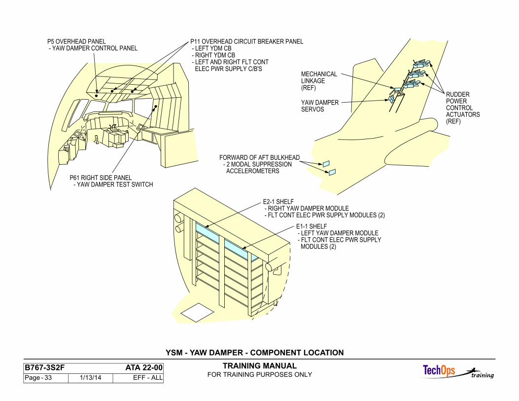
YSM - YAW DAMPER - COMPONENT LOCATION
Flight Compartment
The left and right YSM and CSEU circuit breakers are on the P11 overhead circuit breaker panel.
The yaw damper control panel is on the P5 overhead panel.
The yaw damper test switch is on the P61 right side panel.
Main Equipment Center
The yaw damper/stabilizer trim modules are on the E1-1 and E2-1 shelves.
Vertical Stabilizer
Two yaw damper servos are in the rear spar of the vertical stabilizer. Access is through the trailing edge service access panel of the vertical stabilizer.
Aft Cargo Compartment
Two modal suppression (M/S) accelerometers are in the ceiling of the aft cargo compartment. Access to these accelerometers is through the aft cargo door.
TRAINING MANUALFOR TRAINING PURPOSES ONLY
B767-3S2F ATA 22-00 Page - 33 1/13/14 EFF - ALL
P5 OVERHEAD PANEL - LEFT YDM CB
MECHANICAL
YAW DAMPERSERVOS
E2-1 SHELF
E1-1 SHELF
- RIGHT YDM CB - LEFT AND RIGHT FLT CONT ELEC PWR SUPPLY C/B'S
- RIGHT YAW DAMPER MODULE - FLT CONT ELEC PWR SUPPLY MODULES (2)
- LEFT YAW DAMPER MODULE - FLT CONT ELEC PWR SUPPLY MODULES (2)
P11 OVERHEAD CIRCUIT BREAKER PANEL - YAW DAMPER CONTROL PANEL
POWERCONTROL
RUDDER
ACTUATORS
LINKAGE(REF)
- YAW DAMPER TEST SWITCHP61 RIGHT SIDE PANEL
FORWARD OF AFT BULKHEAD- 2 MODAL SUPPRESSION ACCELEROMETERS
(REF)
YSM - YAW DAMPER - COMPONENT LOCATION
TRAINING MANUALFOR TRAINING PURPOSES ONLY
B767-3S2F ATA 22-00 Page - 34 1/13/14 EFF - ALL
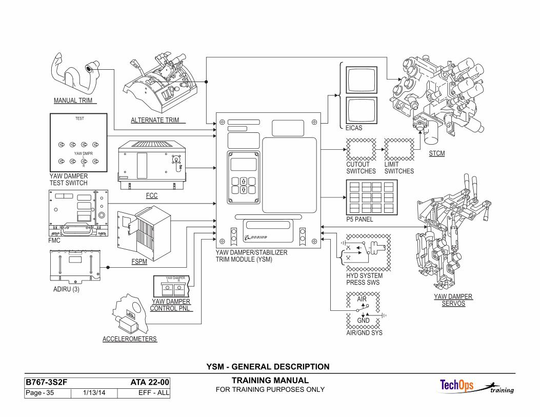
YSM - GENERAL DESCRIPTION
General
The control system electronic unit (CSEU) modules do control functions in the elevator, spoiler, stabilizer, and rudder systems. There are two yaw damper/stabilizer trim modules (YSMs). The YSMs use different inputs to give outputs to actuators and modules.
Stabilizer Trim Function
The YSM gives manual and automatic stabilizer trim commands, mach trim, and unscheduled stabilizer detection and annunciation. The YSMs receive stabilizer trim control inputs from these components:
- FCCs- Alternate electric stab trim switches on the control stand- Manual electric trim switches on the control wheels- Stabilizer position from a flap/slat position module (FSPM).
The YSM gives control signals to a stabilizer trim control module (STCM) through the cutout and limit switches.
The air data/inertial reference units (ADIRU’s) give mach and computed airspeed for the mach trim function.
Caution, advisory, and maintenance messages go to the EICAS computers and pilots overhead panel for display.
Yaw Damper Function
The YSM receives inputs from these components to control the yaw damper actuator:
- Air Data Inertial Reference Units (ADIRU)- Flight management computers (FMCs)- Accelerometers- Position signals from the yaw damper actuator LVDT- FCC.
Hydraulic and Air/Ground Inputs
All the CSEU modules receive hydraulic pressure switch and air ground relay signals for control, test, and fault indication functions.
BITE Functions
The YSM built-in test equipment (BITE) software give fault messages and details to identify yaw damper and stabilizer trim system component faults.
TRAINING MANUALFOR TRAINING PURPOSES ONLY
B767-3S2F ATA 22-00 Page - 35 1/13/14 EFF - ALL
YAW DAMPER/STABILIZER
LIMITSWITCHES
CUTOUTSWITCHES
FCC
YAW DMPRL
R
TEST
FSPM
FMC
HYD SYSTEMPRESS SWS
STCM
YAW DAMPERSERVOS
MANUAL TRIM
ACCELEROMETERS
YAW DAMPERTEST SWITCH
L RYAW DAMPER
YAW DAMPERCONTROL PNL
ALTERNATE TRIM
TRIM MODULE (YSM)
P5 PANEL
EICAS
AIR/GND SYS
AIR
GND
IRU (3)AD
YSM - GENERAL DESCRIPTION
TRAINING MANUALFOR TRAINING PURPOSES ONLY
B767-3S2F ATA 22-00 Page - 36 1/13/14 EFF - ALL
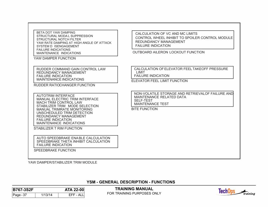
YSM - GENERAL DESCRIPTION - FUNCTIONS
General
The YSM is part of the control system for these flight control surfaces:
- Rudder- Horizontal stabilizer- Spoilers- Elevators- Ailerons
There are seven functions that are done by the YSM.
TRAINING MANUALFOR TRAINING PURPOSES ONLY
B767-3S2F ATA 22-00 Page - 37 1/13/14 EFF - ALL
CONTROL WHEEL INHIBIT TO SPOILER CONTROL MODULE
OUTBOARD AILERON LOCKOUT FUNCTION
CALCULATION OF VC AND MC LIMITS
REDUNDANCY MANAGEMENTFAILURE INDICATION
YAW DAMPER/STABILIZER TRIM MODULE
YAW DAMPER FUNCTION
BETA DOT YAW DAMPINGSTRUCTURAL MODA L SUPPRESSIONSTRUCTURAL NOTCH FILTERYAW RATE DAMPING AT HIGH ANGLE OF ATTACKSYSTEM D ISENGAGEMENTFAILURE INDICATIONSMAINTENANCE INDICATIONS
RUDDER RATIO CHANGER FUNCTION
RUDDER COMMAND GAIN CONTROL LAWREDUNDANCY MANAGEMENTFAILURE INDICATIONMAINTENANCE INDICATIONS
STABILIZER T RIM FUNCTION
AUTOTRIM INTERFACEMANUAL ELECTRIC TRIM INTERFACEMACH TRIM CONTROL LAWSTABILIZER TRIM MODE SELECTIONMANUAL TRIM RATE MONITORINGUNSCHEDULED TRIM DETECTIONREDUNDANCY MANAGEMENTFAILURE INDICATIONMAINTENANCE INDICATIONS
SPEEDBRAKE FUNCTION
AUTO SPEEDBRAKE ENABLE CALCULATIONSPEEDBRAKE THETA INHIBIT CALCULATIONFAILURE INDICATION
ELEVATOR FEEL LIMIT FUNCTION
CALCULATION OF ELEVATOR FEEL TAKEOFF PRESSURELIMIT
FAILURE INDICATION
BITE FUNCTION
NON-VOLATILE STORAGE AND RETRIEVAL OF FAILURE ANDMAINTENANCE RELATED DATASELF-TESTMAINTENANCE TEST
YSM - GENERAL DESCRIPTION - FUNCTIONS
TRAINING MANUALFOR TRAINING PURPOSES ONLY
B767-3S2F ATA 22-00 Page - 38 1/13/14 EFF - ALL
YSM - FAULT RECORDING
General
The YSM contains non-volatile memory (NVM) to record fault data. There is memory to store 256 faults and 64 flight legs.
Fault Storage
Because the EICAS receives discretes from the YSMs that are connected together, the YSMs are the only place to find fault details and identify which YSM detected thefault. Faults can be stored from any of these:
- Power-up test- Ground test- Flight phase faults- Internal YSM faults.
Power-up test is done at initial power-up of the YSM. The test lasts no more than five seconds. The yaw damper INOP amber light is turned on and an EICAS message L/R YAW DAMPER shows during the power-up test. If a fault is detected, the INOP light and EICAS message stay.
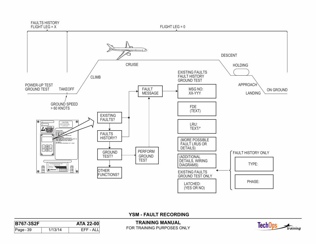
Ground test can be started when the airplane is on the ground and the ground speed is less than 60 knots. The flight phase faults start at takeoff after 60 knots ground speed and ends at landing when the ground speed is less than 60 knots. These are the seven flight phases:
- Takeoff- Climb- Cruise- Holding- Descent- Approach- Landing.
All internal YSM faults are stored regardless of when they occur. Internal faults are identified by the fault message YSM FAULT.
Flight Leg
A new flight leg starts on the transition to takeoff. At takeoff, the faults history flight leg(s) will increment. The current flight leg is shown as flight leg zero.
Fault Record
A fault record is stored for each flight leg in which a fault is recorded. The fault record(s) for each existing fault and ground test fault may contain this data:
- Fault message- Message number- Flight deck effect (FDE)- Most likely line replaceable units (LRUs) at fault (shown as the reference designator for the LRU)- More possible faulty LRUs or details that cause the fault (if any)- Additional details or wiring diagram (if necessary)- Fault latched or not (not shown in fault history).
The fault record(s) for fault history may contain the above details and may include this additional data:
- Fault type (hard, intermittent, or repeated)- Flight phase of first occurrence.
TRAINING MANUALFOR TRAINING PURPOSES ONLY
B767-3S2F ATA 22-00 Page - 39 1/13/14 EFF - ALL
REMOVE THE FRONT PANEL
SLOWLY TO PREVENT DAMAGE
TO INTERNAL CABLE
-CAUTION-
LEVEL
MOD
P/N 285T1122-
SERIAL NUMBER
MFR
SER
ON/OFFMENU
NOYES
H G F E
D C B A
YAW DAMPER/STABILIZER TRIM
MODULE (YSM)
TAKEOFFGROUND TEST
CLIMB
HOLDING
DESCENT
APPROACH
LANDINGON GROUND
FLIGHT LEG = 0
POWER-UP TEST
CRUISE
EXISTINGFAULTS?
FAULTSHISTORY?
GROUNDTEST?
OTHERFUNCTIONS?
MSG NO:XX-YYY
(TEXT)FDE
LRU:TEXT/*
(MORE POSSIBLEFAULT LRUS ORDETAILS)
(ADDITIONALDETAILS, WIRINGDIAGRAMS)
LATCHED:(YES OR NO)
TYPE:
PHASE:
FAULTMESSAGE
FAULT HISTORY ONLY
EXISTING FAULTSGROUND TEST ONLY
EXISTING FAULTS
GROUND TESTFAULT HISTORY
FLIGHT LEG = X
GROUND SPEED> 60 KNOTS
FAULTS HISTORY
GROUNDTEST
PERFORM
YSM - FAULT RECORDING
TRAINING MANUALFOR TRAINING PURPOSES ONLY
B767-3S2F ATA 22-00 Page - 40 1/13/14 EFF - ALL
YSM - BITE
General
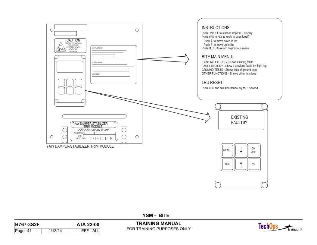
The YSM built-in test equipment (BITE) software provides fault messages and details to identify yaw damper and stabilizer trim system component faults.Entry and exit for BITE is through the BITE control module (BCM) on the front of the YSM. Instructions for the use of the buttons on the BCM are on a placardattached to the front of the YSM.
LRU Reset is available by pressing both the YES and NO buttons at the same time. This performs a maintenance reset which includes a software reset to reset the latched messages.
TRAINING MANUALFOR TRAINING PURPOSES ONLY
B767-3S2F ATA 22-00 Page - 41 1/13/14 EFF - ALL
BITE MAIN MENU:
INSTRUCTIONS:
LRU RESET:
BITE MAIN MENU:
GROUND TESTS - Shows lists of ground tests
YAW DAMPER/STABILIZER TRIM MODULE
FAULTS?
EXISTING
OTHER FUNCTIONS - Shows other functions
FAULT HISTORY - Show s previous faults by flight legEXISTING FAULTS - Sh ows existing faults
Push to move up in listPush MENU to return to previous menu
Push to move down in list
Push YES or NO in reply to questions(?)Push ON/OFF to start or stop BITE display
INSTRUCTIONS:
OFF
ONMENU
YES NO
ELECTROSTATICSENSITIVE
DEVICES
OBSERVE PRECAUTIONSFOR HANDLING
CAUTION
TRIM MODULEYAW DAMPER/STABILIZER
A B C D EMOD LEVEL
S/N
P/N 285T1122-
LRU RESET:Push YES and NO simultaneously for 1 second
YSM - BITE
TRAINING MANUALFOR TRAINING PURPOSES ONLY
B767-3S2F ATA 22-00 Page - 42 1/13/14 EFF - ALL
YSM - FAULT ANNUNCIATION
General
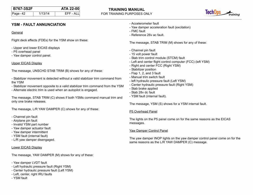
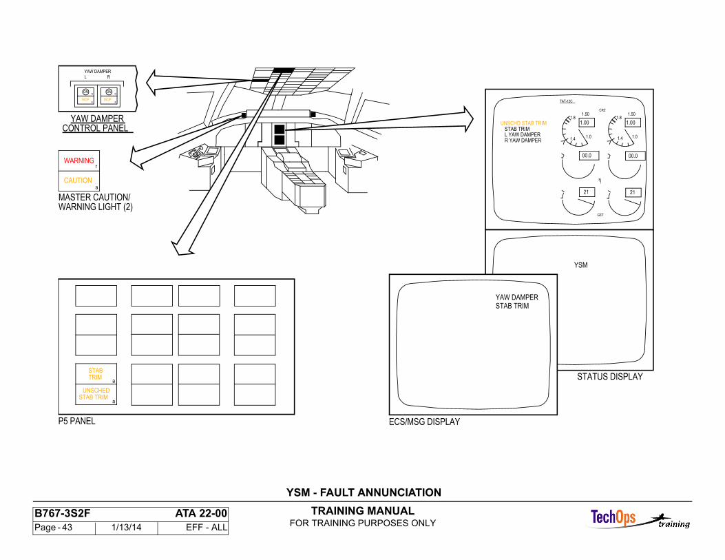
Flight deck effects (FDEs) for the YSM show on these:
- Upper and lower EICAS displays- P5 overhead panel- Yaw damper control panel.
Upper EICAS Display
The message, UNSCHD STAB TRIM (B) shows for any of these:
- Stabilizer movement is detected without a valid stabilizer trim command from the YSM- Stabilizer movement opposite to a valid stabilizer trim command from the YSM- Alternate electric trim is used when an autopilot is engaged.
The message, STAB TRIM (C) shows if both YSMs command manual trim and only one brake releases.
The message, L/R YAW DAMPER (C) shows for any of these:
- Channel pin fault- Airplane pin fault- Invalid YSM part number- Yaw damper actuator fault- Yaw damper intermittent- YSM fault (internal fault)- L/R yaw damper disengaged.
Lower EICAS Display
The message, YAW DAMPER (M) shows for any of these:
- Yaw damper LVDT fault- Left hydraulic pressure fault (Right YSM)- Center hydraulic pressure fault (Left YSM)- Left, center, right IRU faults- YSM fault
- Accelerometer fault- Yaw damper acceleration fault (excitation)- FMC fault- Reference 26v ac fault.
The message, STAB TRIM (M) shows for any of these:
- Channel pin fault- 15 volt power fault- Stab trim control module (STCM) fault- Left and center flight control computer (FCC) (left YSM)- Right and center FCC (Right YSM)- Stabilizer position- Flap 1, 2, and 3 fault- Manual trim switch fault- left hydraulic pressure fault (Left YSM)- Center hydraulic pressure fault (Right YSM)- Stab brake applied- Stab 28v dc fault- YSM fault (internal fault).
The message, YSM (S) shows for a YSM internal fault.
P5 Overhead Panel
The lights on the P5 panel come on for the same reasons as the EICAS messages.
Yaw Damper Control Panel
The yaw damper INOP lights on the yaw damper control panel come on for the same reasons as the L/R YAW DAMPER (C) message.
TRAINING MANUALFOR TRAINING PURPOSES ONLY
B767-3S2F ATA 22-00 Page - 43 1/13/14 EFF - ALL
L YAW DAMPERSTAB TRIM
1.00UNSCHD STAB TRIM
1.0
1.00
GET
21 21
TAT-12C
00.000.0
1N
1.4
1.8
1.01.4
1.81.501.50
CRZ
R YAW DAMPER
YSM
STATUS DISPLAY
STAB TRIMYAW DAMPER
ECS/MSG DISPLAYP5 PANEL
a
aSTAB TRIM
UNSCHED
TRIMSTAB
YAW DAMPER
L R
INOP INOP
ONONw
a
w
a
YAW DAMPERCONTROL PANEL
WARNING LIGHT (2)MASTER CAUTION/
r
aCAUTION
WARNING
YSM - FAULT ANNUNCIATION
TRAINING MANUALFOR TRAINING PURPOSES ONLY
B767-3S2F ATA 22-00 Page - 44 1/13/14 EFF - ALL
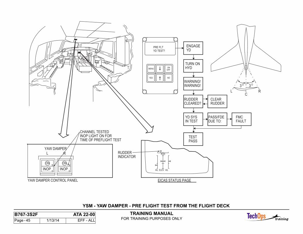
YSM - YAW DAMPER - PRE FLIGHT TEST FROM THE FLIGHT DECK
General
The preflight test uses only the built-in test functions of the yaw damper function. To start the preflight test, push the YAW DMPR test switch on the P61 panel. The test makes sure that the yaw damper functions of the yaw damper/stabilizer trim module (YSM) operate correctly. It also makes sure the yaw damper servos and the switches on the yaw damper control panel operate correctly.
Hydraulics
The center hydraulic system is necessary to do a test of the left yaw damper. The left hydraulic system is necessary to do a test of the right yaw damper.
Interfacing Systems
These systems are necessary during the yaw damper test:
- Rudder and rudder trim control system- IRU aligned and in NAV mode- Air/ground relays- Master dim and test system- EICAS.
Yaw Damper Systems
Push the YES and NO button on the left or right YSM BITE control module (BCM) to do a reset of the YSMs. After 30 seconds, push the left or right yaw damper engage switch on the yaw damper control panel and make sure the ON light comes on, and the INOP light goes off.
Operation
Momentarily push the yaw damper test switch up or down to start the preflight test in the left or right yaw damper module. The INOP annunciator for the channel in test is on during test of each channel. The yaw damper module starts a test in all three IRUs.
The IRUs transmit these normal IRU test values over the ARINC 429 bus:
- Pitch angle- Roll angle- Yaw rate- Roll rate- Lateral acceleration- Ground speed.
Because the YSM is in the preflight test mode, it uses these IRU test values and monitors them for correct performance. If an IRU input is not in limits, an L/C/RIRU fault message shows.
The rudder position moves 3 degrees right, goes back to 0, then moves 3 degrees left, and goes back to 0. The test is complete in fifteen seconds. The yaw damper INOP annunciator goes off approximately fifteen seconds after test start to show satisfactorycompletion of the test.
The mode and status annunciators on the inertial reference mode panel come on during the IRU test mode.
IRS test values can also show on flight compartment indications. See the air data inertial reference unit section for more information about the IRS test (ATA 34-21).
If at least one IRU data is satisfactory, the INOP indications stop, and the system goes back to the ground operation mode. If all three IRU data tests have failures, the INOP indication stays on, and the auto disengage relay de-energizes.
BCM Preflight Test Indications
When a preflight test starts from the flight compartment, the BCM shows YD SYS IN TEST. This lets the person in the main equipment center know there was a preflight test started from the flight compartment.
WARNING: KEEP PERSONNEL AND EQUIPMENT AWAY FROM ALL CONTROL SURFACES WHEN HYDRAULIC POWER IS SUPPLIED. INJURY TO A PERSON OR DAMAGE TO EQUIPMENT CAN OCCUR WHEN HYDRAULIC POWER IS SUPPLIED.
TRAINING MANUALFOR TRAINING PURPOSES ONLY
B767-3S2F ATA 22-00 Page - 45 1/13/14 EFF - ALL
RUD
AIL ELEV AIL
EICAS STATUS PAGE
RUDDERINDICATOR
L R
YAW DAMPER
w
a
ONw
aINOP
ON
INOP
YAW DAMPER CONTROL PANEL
INOP LIGHT ON FOR
RC
L
CHANNEL TESTED
YD TEST?
PRE FLT
OFFON
MENU
YES NO
ENGAGEYD
TURN ONHYD
RUDDERCLEARED?
YD SYSIN TEST
TESTPASS
FMCFAULT
PASS/FDEDUE TO:
WARNING!WARNING!
CLEARRUDDER
3 O3 O
TIME OF PREFLIGHT TEST
YSM - YAW DAMPER - PRE FLIGHT TEST FROM THE FLIGHT DECK
TRAINING MANUALFOR TRAINING PURPOSES ONLY
B767-3S2F ATA 22-00 Page - 46 1/13/14 EFF - ALL
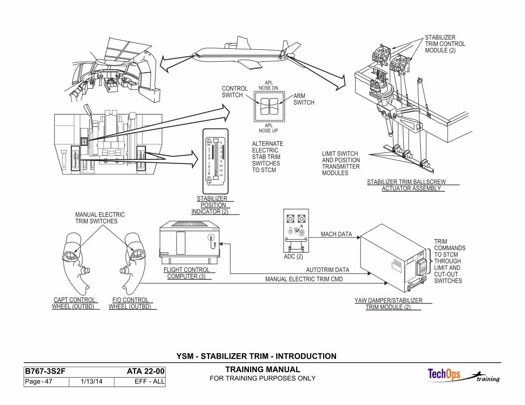
YSM - STABILIZER TRIM - INTRODUCTION
Purpose
The horizontal stabilizer is a moveable airfoil that adjusts the airplane trim in the pitch axis. As the aerodynamic characteristics of the airplane change, theangle of attack of the stabilizer changes to hold the airplane longitudinal stability.
Movement of the stabilizer leading edge up gives the airplane nose down trim. Movement of the stabilizer leading edge down gives the airplane nose up trim.Stabilizer trim is done by these trim modes:
- Manual electric or alternate electric stabilizer trim switches - the pilot gives stabilizer trim commands- Auto trim mode - an engaged autopilot (FCC) gives stabilizer trim commands- Mach trim mode - retraction of the flaps cause stabilizer trim as Mach increases.
Automatic stabilizer trim and Mach trim modes have a relation to the manual stabilizer modes and use common system components.
TRAINING MANUALFOR TRAINING PURPOSES ONLY
B767-3S2F ATA 22-00 Page - 47 1/13/14 EFF - ALL
YSM - STABILIZER TRIM - INTRODUCTION
WHEEL (OUTBD)F/O CONTROL
WHEEL (OUTBD)CAPT CONTROL
AUTOTRIM DATA
MANUAL ELECTRIC TRIM CMD
MACH DATA
FLIGHT CONTROL
TRIM SWITCHESMANUAL ELECTRIC
CONTROLSWITCH ARM
SWITCH
ALTERNATE
STAB TRIM
STABILIZER
INDICATOR (2)
COMPUTER (3)
YAW DAMPER/STABILIZERTRIM MODULE (2)
TO STCM
TRIMCOMMANDSTO STCMTHROUGHLIMIT ANDCUT-OUTSWITCHES
POSITION
ELECTRIC
SWITCHES
COLLINS
NOSE UPAPL
APLNOSE DN
TEST
FUNCTIONALTEST
ADC FAIL
EXTERNAL
FAULTSENSOR ONLY
ADC (2)
STABILIZER TRIM BALLSCREWACTUATOR ASSEMBLY
AND POSITIONLIMIT SWITCH
TRANSMITTER
MODULE (2)TRIM CONTROLSTABILIZER
MODULES
TRAINING MANUALFOR TRAINING PURPOSES ONLY
B767-3S2F ATA 22-00 Page - 48 1/13/14 EFF - ALL
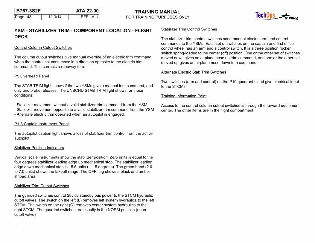
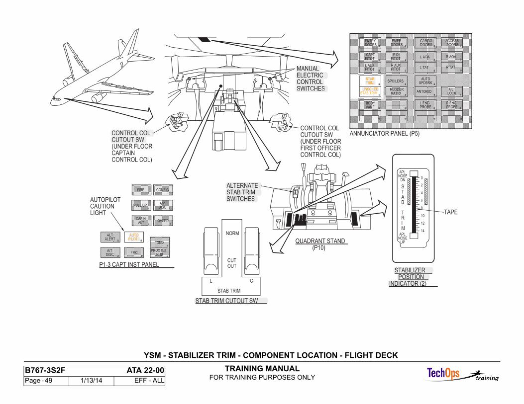
YSM - STABILIZER TRIM - COMPONENT LOCATION - FLIGHT DECK
Control Column Cutout Switches
The column cutout switches give manual override of an electric trim command when the control columns move in a direction opposite to the electric trim command. This corrects a runaway trim.
P5 Overhead Panel
The STAB TRIM light shows if the two YSMs give a manual trim command, and only one brake releases. The UNSCHD STAB TRIM light shows for these conditions:
- Stabilizer movement without a valid stabilizer trim command from the YSM- Stabilizer movement opposite to a valid stabilizer trim command from the YSM- Alternate electric trim operated when an autopilot is engaged.
P1-3 Captain Instrument Panel
The autopilot caution light shows a loss of stabilizer trim control from the active autopilot.
Stabilizer Position Indicators
Vertical scale instruments show the stabilizer position. Zero units is equal to the four degrees stabilizer leading edge up mechanical stop. The stabilizer leading edge down mechanical stop is 15.5 units (-11.5 degrees). The green band (2.0 to 7.0 units) shows the takeoff range. The OFF flag shows a black and amber striped area.
Stabilizer Trim Cutout Switches
The guarded switches control 28v dc standby bus power to the STCM hydraulic cutoff valves. The switch on the left (L) removes left system hydraulics to the leftSTCM. The switch on the right (C) removes center system hydraulics to the right STCM. The guarded switches are usually in the NORM position (open cutoff valve)
.
Stabilizer Trim Control Switches
The stabilizer trim control switches send manual electric arm and control commands to the YSMs. Each set of switches on the captain and first officer control wheel has an arm and a control switch. It is a three position rocker switch spring-loaded to the center (off) position. One or the other set of switches moved down gives an airplane nose up trim command, and one or the other set moved up gives an airplane nose down trim command.
Alternate Electric Stab Trim Switches
Two switches (arm and control) on the P10 quadrant stand give electrical input to the STCMs.
Training Information Point
Access to the control column cutout switches is through the forward equipment center. The other items are in the flight compartment.
TRAINING MANUALFOR TRAINING PURPOSES ONLY
B767-3S2F ATA 22-00 Page - 49 1/13/14 EFF - ALL
YSM - STABILIZER TRIM - COMPONENT LOCATION - FLIGHT DECK
CABINALT
OVSPD
PULL UPA/P
DISC
CONFIGFIRE
rr
r r
r r
MANUALELECTRICCONTROLSWITCHES
TAPE
ANNUNCIATOR PANEL (P5)
DOORSENTRY
CAPTPITOT
L AUXPITOT
STABTRIM
STAB TRIMUNSCHED
a
DOORSEMER
PITOTF O
R AUXPITOT
SPOILERS
RUDDERRATIO
CARGODOORS
L AOA
L TAT
AUTOSPDBRK
ANTISKID
DOORSACCESS
R AOA
AILLOCK
R ENGPROBEw
w w w
a
w
a a
a
a
a
a
a
a
a
a
a
a
a
a
w
a
aa
aa
R TAT
L ENGPROBE
BODYVANE
NORM
OUT
ALERT
DISCFMC
GND
INHBPROX G/SA/T
ALT
AUTOPILOT
STAB TRIM
P1-3 CAPT INST PANELCUT
CAUTIONLIGHT
STABILIZERPOSITION
INDICATOR (2)
a
a
aa
a a
L C
ALTERNATESTAB TRIMSWITCHES
AUTOPILOT
STAB TRIM CUTOUT SW
QUADRANT STAND(P10)
(UNDER FLOOR
CONTROL COLCUTOUT SW
CAPTAINCONTROL COL)
(UNDER FLOOR
CONTROL COLCUTOUT SW
FIRST OFFICERCONTROL COL)
0
2
4
6
8
10
12
14
APLNOSE
DN
APLNOSE
UP
STAB
TRIM
CONTROL COLCUTOUT SW
MANUALELECTRICCONTROLSWITCHES
STABTRIM
UNSCHED
AUTOPILOT
STAB TRIM CUTOUT SW
ALTERNATESTAB TRIMSWITCHES
STABILIZERPOSITION
INDICATOR (2

TRAINING MANUALFOR TRAINING PURPOSES ONLY
B767-3S2F ATA 22-00 Page - 50 1/13/14 EFF - ALL
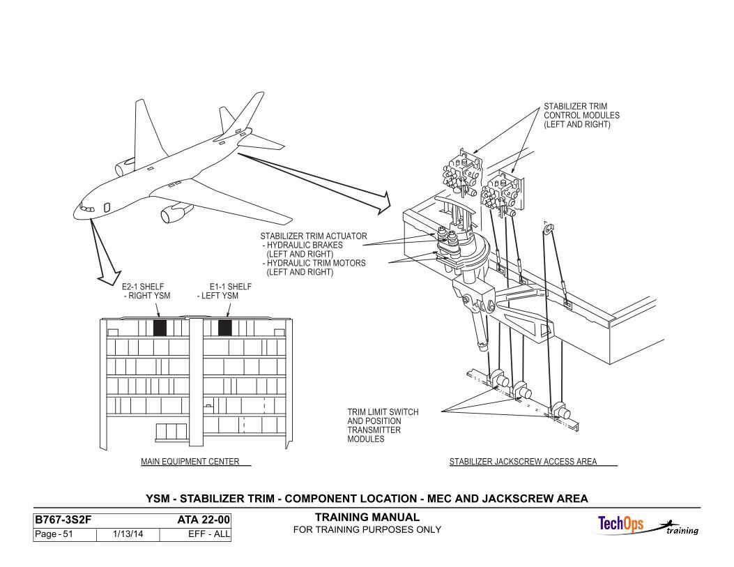
YSM - STABILIZER TRIM - COMPONENT LOCATION - MEC AND JACKSCREW AREA
Main Equipment Center
Yaw damper/stabilizer trim modules (YSMs) are CSEU modules on the CSEU shelf.
Stabilizer Jackscrew Access Area
The stabilizer trim actuator controls trim operation of the horizontal stabilizer.Each trim limit switch and position transmitter module (left, center, and right) contains these components:
- One synchro- One rotary variable differential transformer(RVDT).
All three modules are interchangeable.
TRAINING MANUALFOR TRAINING PURPOSES ONLY
B767-3S2F ATA 22-00 Page - 51 1/13/14 EFF - ALL
YSM - STABILIZER TRIM - COMPONENT LOCATION - MEC AND JACKSCREW AREA
STABILIZER JACKSCREW ACCESS AREAMAIN EQUIPMENT CENTER
- RIGHT YSM - LEFT YSME1-1 SHELFE2-1 SHELF
- HYDRAULIC BRAKESSTABILIZER TRIM ACTUATOR
TRIM LIMIT SWITCHAND POSITIONTRANSMITTERMODULES
(LEFT AND RIGHT) - HYDRAULIC TRIM MOTORS (LEFT AND RIGHT)
STABILIZER TRIM
(LEFT AND RIGHT)CONTROL MODULES
TRAINING MANUALFOR TRAINING PURPOSES ONLY
B767-3S2F ATA 22-00 Page - 52 1/13/14 EFF - ALL
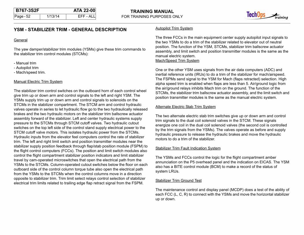
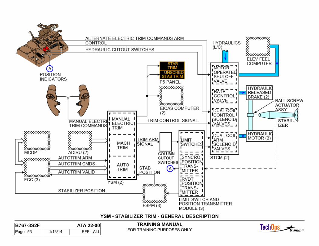
YSM - STABILIZER TRIM - GENERAL DESCRIPTION
General
The yaw damper/stabilizer trim modules (YSMs) give these trim commands to the stabilizer trim control modules (STCMs):
- Manual trim- Autopilot trim- Mach/speed trim.
Manual Electric Trim System
The stabilizer trim control switches on the outboard horn of each control wheel give trim up or down arm and control signals to the left and right YSM. The YSMs supply trim up or down arm and control signals to solenoids on the STCMs in the stabilizer compartment. The STCM arm and control hydraulic valves operate in series to let hydraulic flow go to the two hydraulically released brakes and the two hydraulic motors on the stabilizer trim ballscrew actuatorassembly forward of the stabilizer. Left and center hydraulic systems supply pressure to the STCMs through STCM cutoff valves. Two hydraulic cutout switches on the top left side of the control stand supply electrical power to the STCM cutoff valve motors. This isolates hydraulic power from the STCMs.Hydraulic inputs from the elevator feel computers control the rate of stabilizer trim. The left and right limit switch and position transmitter modules near thestabilizer supply position feedback through flap/stab position module (FSPM) to the flight control computers (FCCs). The position and limit switch modules alsocontrol the flight compartment stabilizer position indicators and limit stabilizer travel by cam-operated microswitches that open the electrical path from theYSMs to the STCMs. Column-operated cutout switches below the floor on each outboard side of the control column torque tube also open the electrical path from the YSMs to the STCMs when the control columns move in a direction opposite to stabilizer trim. Trim limit select relays control selection of stabilizerelectrical trim limits related to trailing edge flap retract signal from the FSPM.
Autopilot Trim System
The three FCCs in the main equipment center supply autopilot input signals to the two YSMs to do a trim of the stabilizer related to elevator out of neutralposition. The function of the YSM, STCMs, stabilizer trim ballscrew actuator assembly, and limit switch and position transmitter modules is the same as the manual electric system.Mach/Speed Trim System
One or the other YSM uses signals from the air data computers (ADC) and inertial reference units (IRUs) to do a trim of the stabilizer for mach/airspeed. The FSPMs send signal to the YSM for Mach (flaps retracted) selection. High alpha speed trim is enabled when flaps are less than 5. Air/ground logic from the air/ground relays inhibits Mach trim on the ground. The function of the STCMs, the stabilizer trim ballscrew actuator assembly, and the limit switch and position transmitter modules is the same as the manual electric system.
Alternate Electric Stab Trim System
The two alternate electric stab trim switches give up or down arm and control trim signals to the dual coil solenoid valves in the STCM. These signals energize one coil in the dual coil solenoid valves (the second coil is controlled by the trim signals from the YSMs). The valves operate as before and supply hydraulic pressure to release the hydraulic brakes and move the hydraulicmotors to do a trim of the stabilizer.
Stabilizer Trim Fault Indication System
The YSMs and FCCs control the logic for the flight compartment amber annunciation on the P5 overhead panel and the indication on EICAS. The YSM also has a BITE control module (BCM) to make a record of the status ofsystem LRUs.
Stabilizer Trim Ground Test
The maintenance control and display panel (MCDP) does a test of the ability of each FCC (L, C, R) to connect with the YSMs and move the horizontal stabilizer up or down.
TRAINING MANUALFOR TRAINING PURPOSES ONLY
B767-3S2F ATA 22-00 Page - 53 1/13/14 EFF - ALL
YSM - STABILIZER TRIM - GENERAL DESCRIPTION
TRAINING MANUALFOR TRAINING PURPOSES ONLY
B767-3S2F ATA 22-00 Page - 54 1/13/14 EFF - ALL
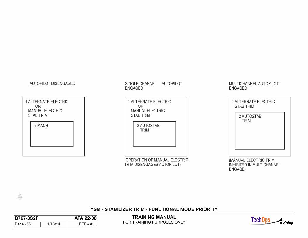
YSM - STABILIZER TRIM - FUNCTIONAL MODE PRIORITY
General
There are four modes for control of stabilizer trim. The mode priority has a relation to the number of autopilot channels engaged. The four modes are:
- Alternate electric trim mode- Manual electric trim mode- Mach trim mode- Automatic stabilizer trim mode.
Autopilot Disengaged
Mach trim enables when the autopilot is not engaged in CMD and alternate electric or manual electric trim is not in use. This occurs automatically and modeselection is not necessary. Operation of the manual electric trim or the alternate electric stab trim mode causes an interrupt of Mach/speed trim commands.
Single Channel Autopilot Engaged
When the autopilot engages in single channel, this is the order of control priority:
- Alternate electric trim mode- Manual electric trim mode- Automatic stabilizer trim mode.
Operation of manual electric trim causes the autotrim valid signal to be set low from the YSM. This causes the FCC to disengage during single channel operation. Operation of alternate electric trim does not disengage the autopilot.
Multi-Channel Autopilot Engaged
When the autopilot is multi-channel engaged (two or more FCCs engaged), this is the order of priority:
- Alternate electric trim mode- Automatic stabilizer trim mode.
Manual electric trim inhibits during multi-channel operation. The YSM does not let the manual electric trim inputs disengage the autopilot.
TRAINING MANUALFOR TRAINING PURPOSES ONLY
B767-3S2F ATA 22-00 Page - 55 1/13/14 EFF - ALL
YSM - STABILIZER TRIM - FUNCTIONAL MODE PRIORITY
TRIM2 AUTOSTAB
STAB TRIM
2 MACH
OR1 ALTERNATE ELECTRIC
MANUAL ELECTRIC STAB TRIM
OR1 ALTERNATE ELECTRIC
MANUAL ELECTRIC STAB TRIM1 ALTERNATE ELECTRIC
TRIM DISENGAGES AUTOPILOT)(OPERATION OF MANUAL ELECTRIC
ENGAGED
ENGAGE)INHIBITED IN MULTICHANNEL(MANUAL ELECT RIC TRIM
ENGAGEDMULTICHANNEL AUTOPILOTSINGLE CHANNEL AUTOPILOTAUTOPILOT DISENGAGED
2 AUTOSTAB TRIM
TRAINING MANUALFOR TRAINING PURPOSES ONLY
B767-3S2F ATA 22-00 Page - 56 1/13/14 EFF - ALL
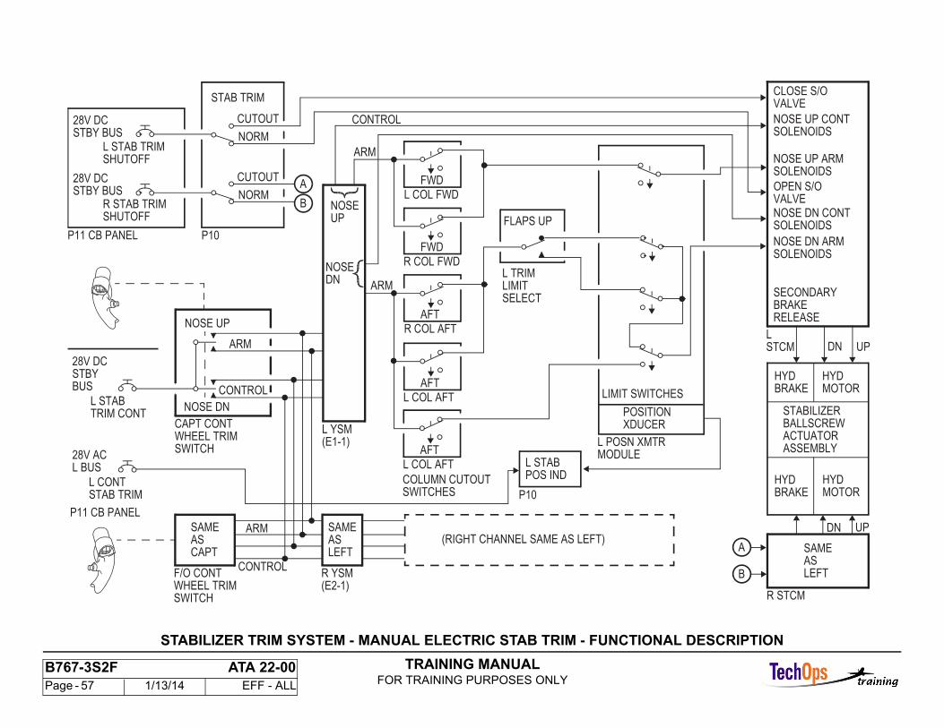
STABILIZER TRIM SYSTEM - MANUAL ELECTRIC STAB TRIM - FUNCTIONAL DESCRIPTION
Manual Electric Control Mode
Operation of the captain or first officer control wheel switches gives full trim rate to the horizontal stabilizer (approximately 0.5/sec on the ground). The STCMs supply hydraulic power to release brakes and hydraulic motors to move the stabilizer through the stabilizer trim ball screw actuator assembly. The arm portion of the signal goes through column cutout and limit switches which open the trim signal to STCM solenoids. This stops stabilizer trim.
The stabilizer trim column cutout switches give manual override of any electric trim command if there is a runaway stabilizer. It breaks the path for electrictrim commands when you move the control columns in a direction opposite to the commanded trim direction. The normally closed switches are in parallel to give column asymmetry protection. If you move the columns forwardmore than the limit, it stops a stabilizer airplane nose up command. If you move the columns aft more than the limit, it stops a stabilizer airplane nose downcommand.
Two switches in the limit switch and position transmitter modules limit the travel of the stabilizer in a leading edge up direction (airplane nose downtrim). The leading edge up electrical limit is 1.5 units for flaps retracted and 0.25 units for flaps not retracted.
TRAINING MANUALFOR TRAINING PURPOSES ONLY
B767-3S2F ATA 22-00 Page - 57 1/13/14 EFF - ALL
R STCM
28V DC
L BUS
CAPT CONTWHEEL TRIM
NOSE DN
NOSE UP
28V DC
28V DC
STAB TRIM
NORM
P10
ARM
HYDBRAKE
HYDMOTOR
HYDBRAKE
HYDMOTOR
STABILIZERBALLSCREWACTUATORASSEMBLY
L CONT
28V AC
STBY
L STAB
L STAB TRIMSHUTOFF
R STAB TRIMSHUTOFF
STBY BUS
STBY BUS
COLUMN CUTOUT
P11 CB PANEL
L YSM(E1-1)
P11 CB PANEL
R YSM(E2-1)
SAMEAS LEFT
CUTOUT
SAMEASLEFT
FWD
L COL FWDNOSEUP
NOSEDN
SOLENOIDS
SOLENOIDS
SOLENOIDS
SOLENOIDSNOSE UP CONT
NOSE UP ARM
NOSE DN ARM
NOSE DN CONT
SECONDARY
CLOSE S/OVALVE
OPEN S/OVALVE
BRAKERELEASE
POSITIONXDUCER
L POSN XMTR
LIMIT SWITCHES
MODULE
UPDN
DN UP
SWITCHES
ARM
CONTROL
L STABPOS IND
STAB TRIM P10
L
F/O CONTWHEEL TRIMSWITCH
SWITCH
(RIGHT CHANNEL SAME AS LEFT)
ARM
SAMEASCAPT
ARM
CONTROL
TRIM CONT
CUTOUT
NORM
A
B
FWD
R COL FWD
AFT
R COL AFT
AFT
L COL AFT
A
B
STCM
BUS CONTROL
FLAPS UP
L TRIMLIMITSELECT
AFT
L COL AFT
STABILIZER TRIM SYSTEM - MANUAL ELECTRIC STAB TRIM - FUNCTIONAL DESCRIPTION

TRAINING MANUALFOR TRAINING PURPOSES ONLY
B767-3S2F ATA 22-00 Page - 58 1/13/14 EFF - ALL
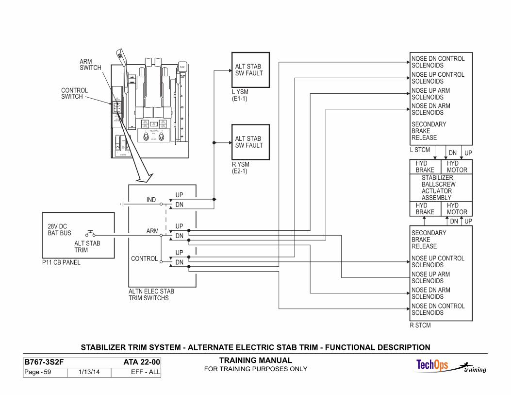
STABILIZER TRIM SYSTEM - ALTERNATE ELECTRIC STAB TRIM - FUNCTIONAL DESCRIPTION
Alternate Electric Stab Trim
Operation of the alternate electric stab trim switches gives full rate trim. Movement of the arm (right) and the control (left) switches forward or aft gives a nose up or nose down signal. When you release the switches, a spring moves the switches back to the neutral position.
The nose up or down arm and control signals go directly to the two STCMs.
A normally open micro-switch closes with arm switch movement to connect a ground to the stabilizer trim aileron lockout modules (SAM). This inhibits the Mach trim function. The SAM monitors the micro-switch position. If the switch is in the closed position for more than 30 seconds, and one of the systems hashydraulic pressure, the manual lever switch fault ball sets on the SAMs.
TRAINING MANUALFOR TRAINING PURPOSES ONLY
B767-3S2F ATA 22-00 Page - 59 1/13/14 EFF - ALL
R STCM
SOLENOIDS
SOLENOIDS
SOLENOIDS
28V DC
NOSE UP CONTROL
NOSE UP ARM
NOSE DN ARM
SECONDARYBRAKERELEASE
HYDBRAKE
HYDMOTOR
HYDBRAKE
HYDMOTOR
DN
DN
STABILIZERBALLSCREWACTUATORASSEMBLY
ALT STAB
BAT BUS
R YSM
P11 CB PANEL
L YSM(E1-1)
L STCM
(E2-1)
UP
UP
SOLENOIDS
SOLENOIDS
SOLENOIDS
SOLENOIDSNOSE UP ARM
NOSE UP CONTROL
NOSE DN ARM
NOSE DN CONTROL
SECONDARYBRAKERELEASE
TRIM SWITCHSALTN ELEC STAB
CONTROL
ARM
DN
UP
DN
UP
DN
UP
ALT STABSW FAULT
ALT STABSW FAULT
SOLENOIDSNOSE DN CONTROL
IND
TRIM
OUT
NORM
STAB TRIM
L C
CUT
FLAP
ALTNSTAB TRIM
APLNOSE DN
APLNOSE UP
ENGVALVE a
SPARVALVE a
RL FUEL CONTROL
RUN
CUT OFF
a
REVISLN
a
SPARVALVE
a
ENGVALVE
SWITCHARM
SWITCHCONTROL
STABILIZER TRIM SYSTEM - ALTERNATE ELECTRIC STAB TRIM - FUNCTIONAL DESCRIPTION
TRAINING MANUALFOR TRAINING PURPOSES ONLY
B767-3S2F ATA 22-00 Page - 60 1/13/14 EFF - ALL
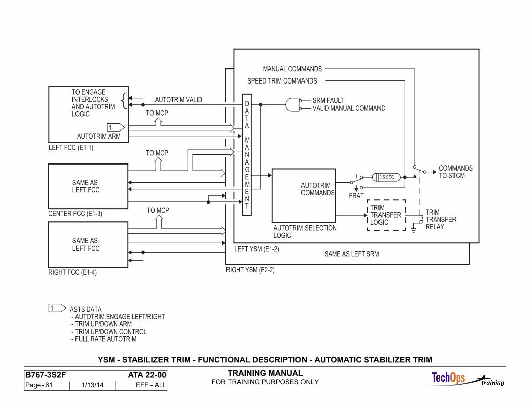
YSM - STABILIZER TRIM - FUNCTIONAL DESCRIPTION - AUTOMATIC STABILIZER TRIM
General Description
Automatic trim of the stabilizer is done by trim up and trim down commands from an engaged FCC. The first FCC engaged starts communications with its YSM. The left and right FCCs interface with the left and right YSMs respectively. The center FCC interfaces with both YSMs. Each FCC has logic that determines which YSM processesthe FCC autotrim commands. The first engaged FCC provides the autotrim signals and controls YSM selection. When multichannel engaged, if the first FCC in command disengages or is unable to provide reliable autotrim commands, an automatic change to another FCCoccurs. Autotrim failure annunciation is controlled by fault logic in the FCC in control.
Functional Description
Each YSM makes an autotrim valid discrete if it is capable of the trim function.
The FCC sends a discrete autotrim arm signal to the YSM(s). This arms the YSM(s) for data reception. The FCC then sends an engage discrete and autotrim commands on the FCC-YSM 429 bus interface based on elevator outof neutral position. The YSM processes the FCC autotrim commands through arm and control microprocessors to provide up and down signals to the stab trim control module (STCM).
TRAINING MANUALFOR TRAINING PURPOSES ONLY
B767-3S2F ATA 22-00 Page - 61 1/13/14 EFF - ALL
YSM - STABILIZER TRIM - FUNCTIONAL DESCRIPTION - AUTOMATIC STABILIZER TRIM
LEFT FCC (E1-1)
LEFT YSM (E1-2)
AUTOTRIM ARM
AUTOTRIM
ASTS DATA
SAME AS LEFT SRM
RIGHT YSM (E2-2)
AUTOTRIM VALID
- AUTOTRIM ENGAGE LEFT/RIGHT
TO MCP
TO MCP
- FULL RATE AUTOTRIM - TRIM UP/DOWN CONTROL - TRIM UP/DOWN ARM
SAME ASLEFT FCC
RIGHT FCC (E1-4)
TO MCP
LOGICTRANSFERTRIM
MANUAL COMMANDS
SPEED TRIM COMMANDS
FRAT
TRIMTRANSFER
COMMANDSTO STCM
RELAY
TO ENGAGEINTERLOCKSAND AUTOTRIMLOGIC
CENTER FCC (E1-3)
VALID MANUAL COMMANDSRM FAULT
COMMANDS
3.5 SEC
1
1
SAME ASLEFT FCC
DATA
MANAGEMENT
AUTOTRIM SELECTIONLOGIC
TRAINING MANUALFOR TRAINING PURPOSES ONLY
B767-3S2F ATA 22-00 Page - 62 1/13/14 EFF - ALL
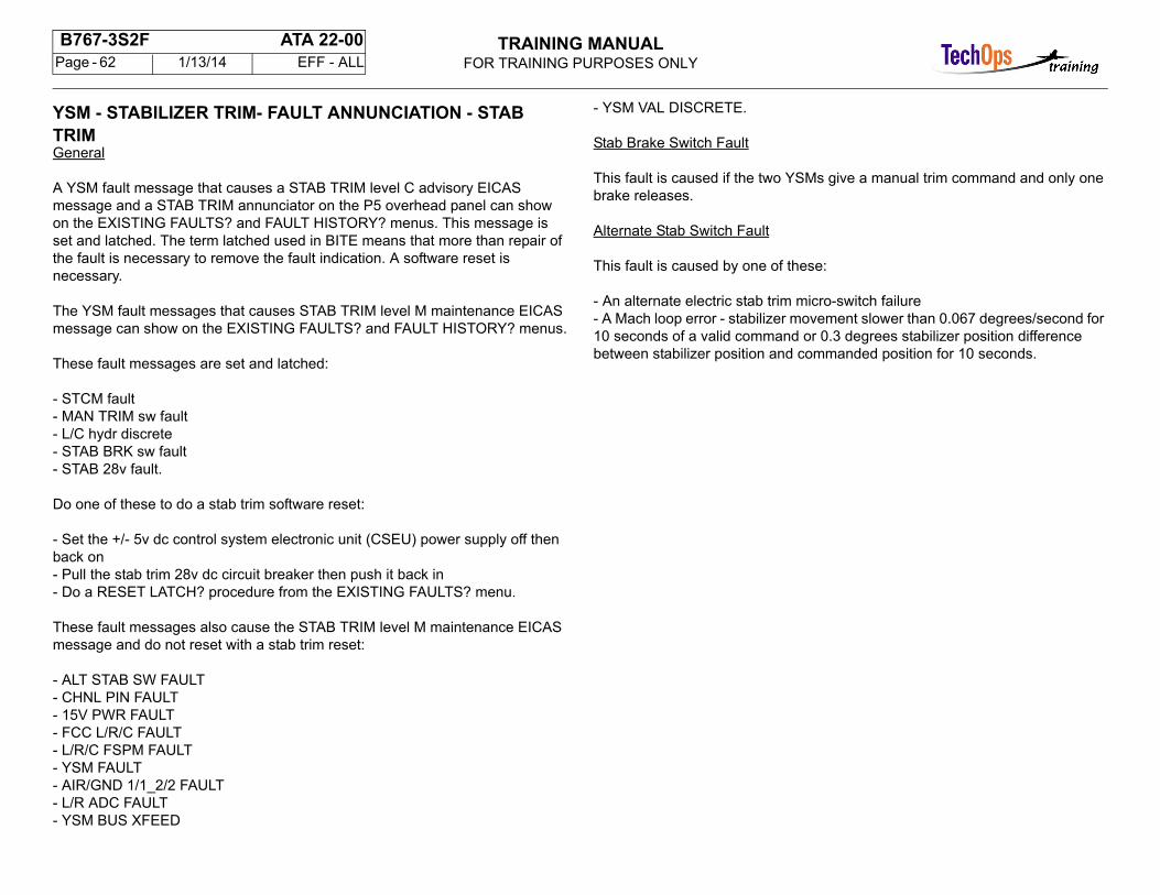
YSM - STABILIZER TRIM- FAULT ANNUNCIATION - STAB TRIM General
A YSM fault message that causes a STAB TRIM level C advisory EICAS message and a STAB TRIM annunciator on the P5 overhead panel can show on the EXISTING FAULTS? and FAULT HISTORY? menus. This message is set and latched. The term latched used in BITE means that more than repair of the fault is necessary to remove the fault indication. A software reset is necessary.
The YSM fault messages that causes STAB TRIM level M maintenance EICAS message can show on the EXISTING FAULTS? and FAULT HISTORY? menus.
These fault messages are set and latched:
- STCM fault- MAN TRIM sw fault- L/C hydr discrete- STAB BRK sw fault- STAB 28v fault.
Do one of these to do a stab trim software reset:
- Set the +/- 5v dc control system electronic unit (CSEU) power supply off then back on- Pull the stab trim 28v dc circuit breaker then push it back in- Do a RESET LATCH? procedure from the EXISTING FAULTS? menu.
These fault messages also cause the STAB TRIM level M maintenance EICAS message and do not reset with a stab trim reset:
- ALT STAB SW FAULT- CHNL PIN FAULT- 15V PWR FAULT- FCC L/R/C FAULT- L/R/C FSPM FAULT- YSM FAULT- AIR/GND 1/1_2/2 FAULT- L/R ADC FAULT- YSM BUS XFEED
- YSM VAL DISCRETE.
Stab Brake Switch Fault
This fault is caused if the two YSMs give a manual trim command and only one brake releases.
Alternate Stab Switch Fault
This fault is caused by one of these:
- An alternate electric stab trim micro-switch failure- A Mach loop error - stabilizer movement slower than 0.067 degrees/second for 10 seconds of a valid command or 0.3 degrees stabilizer position difference between stabilizer position and commanded position for 10 seconds.
TRAINING MANUALFOR TRAINING PURPOSES ONLY
B767-3S2F ATA 22-00 Page - 63 1/13/14 EFF - ALL
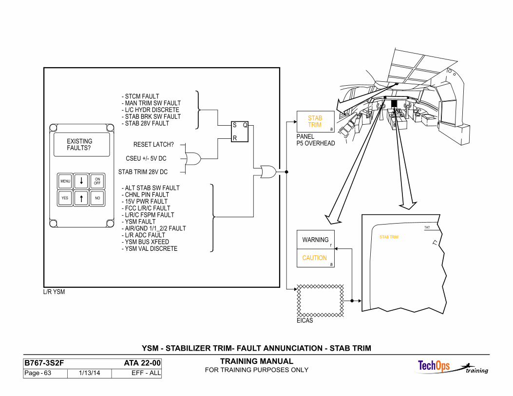
TAT
STAB TRIM
L/R YSM
- CHNL PIN FAULT- 15V PWR FAULT
- STCM FAULT
- FCC L/R/C FAULT- L/R/C FSPM FAULT
- MAN TRIM SW FAULT- L/C HYDR DISCRETE- STAB BRK SW FAULT- STAB 28V FAULT
- YSM FAULT- AIR/GND 1/1_2/2 FAULT- L/R ADC FAULT- YSM BUS XFEED- YSM VAL DISCRETE
WARNING
CAUTION
r
a
S
R
Q
RESET LATCH?
CSEU +/- 5V DC
STAB TRIM 28V DC
- ALT STAB SW FAULT
P5 OVERHEADPANEL
TRIMSTAB
a
FAULTS?EXISTING
OFFON
MENU
YES NO
EICAS
YSM - STABILIZER TRIM- FAULT ANNUNCIATION - STAB TRIM
TRAINING MANUALFOR TRAINING PURPOSES ONLY
B767-3S2F ATA 22-00 Page - 64 1/13/14 EFF - ALL
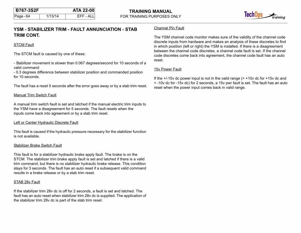
YSM - STABILIZER TRIM - FAULT ANNUNCIATION - STAB TRIM CONT.
STCM Fault
The STCM fault is caused by one of these:
- Stabilizer movement is slower than 0.067 degrees/second for 10 seconds of a valid command- 0.3 degrees difference between stabilizer position and commanded position for 10 seconds.
The fault has a reset 5 seconds after the error goes away or by a stab trim reset.
Manual Trim Switch Fault
A manual trim switch fault is set and latched if the manual electric trim inputs to the YSM have a disagreement for 5 seconds. The fault resets when theinputs come back into agreement or by a stab trim reset.
Left or Center Hydraulic Discrete Fault
This fault is caused if the hydraulic pressure necessary for the stabilizer function is not available.
Stabilizer Brake Switch Fault
This fault is for a stabilizer hydraulic brake apply fault. The brake is on the STCM. The stabilizer trim brake apply fault is set and latched if there is a valid trim command, but there is no stabilizer hydraulic brake release. This conditionstays for 3 seconds. The fault has an auto reset if a subsequent valid command results in a brake release or by a stab trim reset.
STAB 28v Fault
If the stabilizer trim 28v dc is off for 2 seconds, a fault is set and latched. The fault has an auto reset when stabilizer trim 28v dc is supplied. The application of the stabilizer trim 28v dc is part of the stab trim reset.
Channel Pin Fault
The YSM channel code monitor makes sure of the validity of the channel code discrete inputs from hardware and makes an analysis of these discretes to find in which position (left or right) the YSM is installed. If there is a disagreement between the channel code discretes, a channel code fault is set. If the channel code discretes come back into agreement, the channel code fault has an auto reset.
15v Power Fault
If the +/-15v dc power input is not in the valid range (> +10v dc for +15v dc and < -10v dc for -15v dc) for 2 seconds, a 15v pwr fault is set. The fault has an autoreset when the power input comes back in valid range.
TRAINING MANUALFOR TRAINING PURPOSES ONLY
B767-3S2F ATA 22-00 Page - 65 1/13/14 EFF - ALL
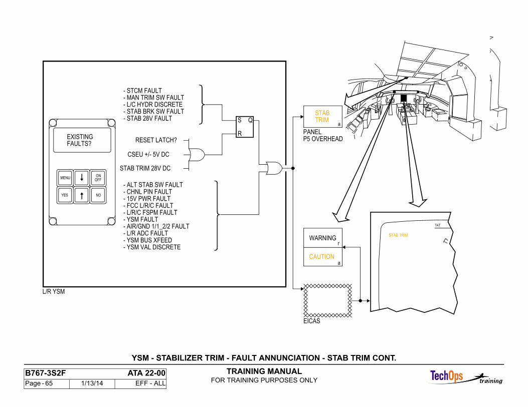
YSM - STABILIZER TRIM - FAULT ANNUNCIATION - STAB TRIM CONT.
TAT
STAB TRIM
L/R YSM
- CHNL PIN FAULT- 15V PWR FAULT
- STCM FAULT
- FCC L/R/C FAULT- L/R/C FSPM FAULT
- MAN TRIM SW FAULT- L/C HYDR DISCRETE- STAB BRK SW FAULT- STAB 28V FAULT
- YSM FAULT- AIR/GND 1/1_2/2 FAULT- L/R ADC FAULT- YSM BUS XFEED- YSM VAL DISCRETE
WARNING
CAUTION
r
a
S
R
Q
RESET LATCH?
CSEU +/- 5V DC
STAB TRIM 28V DC
- ALT STAB SW FAULT
P5 OVERHEADPANEL
TRIMSTAB
a
FAULTS?EXISTING
OFFON
MENU
YES NO
EICAS
TRAINING MANUALFOR TRAINING PURPOSES ONLY
B767-3S2F ATA 22-00 Page - 66 1/13/14 EFF - ALL
YSM - STABILIZER TRIM- FAULT ANNUNCIATION - STAB TRIM CONT.
FCC Fault
An FCC fault is set for a FCC bus if a watchdog, parity, coincidence, or engage fault is set for that bus. On the ground, FCC faults have an auto reset when databecomes valid. In the air, FCC faults have an auto reset when the data becomes valid and stays valid for 2.25 seconds.
Left, Right, and Center FSPM Fault
The FSPM gives flap and stabilizer position data to the YSM.
If the stabilizer position input is not more than 1v dc for 2 seconds, a left or right FSPM fault is set. The fault has an auto reset if the stabilizer positioncomes back in the correct range.
Comparison and range monitor is done on flap position inputs to YSM software to make sure of the validity of the data.
If the flap position input value is not in the valid range and stays out of that range for 2 seconds, a left, center, or right FSPM fault is set. If the airplane is on the ground and the flap position input comes back to a valid range, the fault has an auto reset.
Comparison monitor is only done in the air. If a flap position disagrees with the selected position for 15 seconds, a left, center, or right FSPM fault is set.
YSM Fault
A stabilizer trim YSM fault is set if a trim command coincidence fault (trim commands between the two microprocessors disagree) or trim mode coincidence fault (the stabilizer trim mode between the two microprocessors disagree) occurs. On the ground, a stabilizer trim YSM fault has an auto reset when the coincidence fault goes away. In the air, a stabilizer trim YSM fault has an auto reset when the coincidence fault goes away for 15 seconds. After the stabilizer trim YSM fault has an auto reset four times, the next fault is set and latched until the airplane is on the ground and the coincidence fault goes away.
Air/Ground 1, 1 and 2, 2 Fault
The YSM uses majority vote logic to find the in-air or on-ground status of the airplane. If 2 of 3 air/ground discrete inputs show in air, the YSM uses the in-airstatus. The same condition applies for on-ground. If one air/ground discrete input is not valid, the YSM uses the last valid value for that discrete andcontinues majority vote. If two air/ground discertes are not valid, the YSM goes to in-air status. The YSM on-ground monitor compares the majority votedstatus with each of the three air/ground discrete inputs. If there is a disagreement for two seconds, a fault is set against the invalid air/ground discrete. This fault can not reset until the not valid discrete agrees with the majority voting.
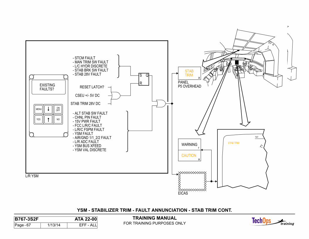
TRAINING MANUALFOR TRAINING PURPOSES ONLY
B767-3S2F ATA 22-00 Page - 67 1/13/14 EFF - ALL
YSM - STABILIZER TRIM - FAULT ANNUNCIATION - STAB TRIM CONT.
TAT
STAB TRIM
L/R YSM
- CHNL PIN FAULT- 15V PWR FAULT
- STCM FAULT
- FCC L/R/C FAULT- L/R/C FSPM FAULT
- MAN TRIM SW FAULT- L/C HYDR DISCRETE- STAB BRK SW FAULT- STAB 28V FAULT
- YSM FAULT- AIR/GND 1/1_2/2 FAULT- L/R ADC FAULT- YSM BUS XFEED- YSM VAL DISCRETE
WARNING
CAUTION
r
a
S
R
Q
RESET LATCH?
CSEU +/- 5V DC
STAB TRIM 28V DC
- ALT STAB SW FAULT
P5 OVERHEADPANEL
TRIMSTAB
a
FAULTS?EXISTING
OFFON
MENU
YES NO
EICAS
TAT
STAB TRIM
L/R YSM
- CHNL PIN FAULT- 15V PWR FAULT
- STCM FAULT
- FCC L/R/C FAULT- L/R/C FSPM FAULT
- MAN TRIM SW FAULT- L/C HYDR DISCRETE- STAB BRK SW FAULT- STAB 28V FAULT
- YSM FAULT- AIR/GND 1/1_2/2 FAULT- L/R ADC FAULT- YSM BUS XFEED- YSM VAL DISCRETE
WARNING
CAUTION
r
a
S
R
Q
RESET LATCH?
CSEU +/- 5V DC
STAB TRIM 28V DC
- ALT STAB SW FAULT
P5 OVERHEADPANEL
TRIMSTAB
a
FAULTS?EXISTING
OFFON
MENU
YES NO
EICAS
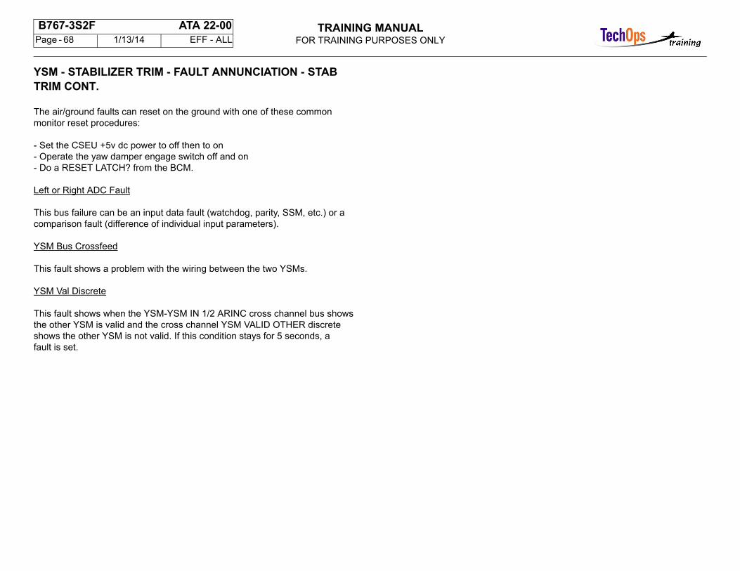
TRAINING MANUALFOR TRAINING PURPOSES ONLY
B767-3S2F ATA 22-00 Page - 68 1/13/14 EFF - ALL
YSM - STABILIZER TRIM - FAULT ANNUNCIATION - STAB TRIM CONT.
The air/ground faults can reset on the ground with one of these common monitor reset procedures:
- Set the CSEU +5v dc power to off then to on- Operate the yaw damper engage switch off and on- Do a RESET LATCH? from the BCM.
Left or Right ADC Fault
This bus failure can be an input data fault (watchdog, parity, SSM, etc.) or a comparison fault (difference of individual input parameters).
YSM Bus Crossfeed
This fault shows a problem with the wiring between the two YSMs.
YSM Val Discrete
This fault shows when the YSM-YSM IN 1/2 ARINC cross channel bus shows the other YSM is valid and the cross channel YSM VALID OTHER discrete shows the other YSM is not valid. If this condition stays for 5 seconds, afault is set.
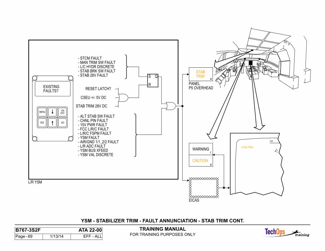
TRAINING MANUALFOR TRAINING PURPOSES ONLY
B767-3S2F ATA 22-00 Page - 69 1/13/14 EFF - ALL
YSM - STABILIZER TRIM - FAULT ANNUNCIATION - STAB TRIM CONT.
TAT
STAB TRIM
L/R YSM
- CHNL PIN FAULT- 15V PWR FAULT
- STCM FAULT
- FCC L/R/C FAULT- L/R/C FSPM FAULT
- MAN TRIM SW FAULT- L/C HYDR DISCRETE- STAB BRK SW FAULT- STAB 28V FAULT
- YSM FAULT- AIR/GND 1/1_2/2 FAULT- L/R ADC FAULT- YSM BUS XFEED- YSM VAL DISCRETE
WARNING
CAUTION
r
a
S
R
Q
RESET LATCH?
CSEU +/- 5V DC
STAB TRIM 28V DC
- ALT STAB SW FAULT
P5 OVERHEADPANEL
TRIMSTAB
a
FAULTS?EXISTING
OFFON
MENU
YES NO
EICAS
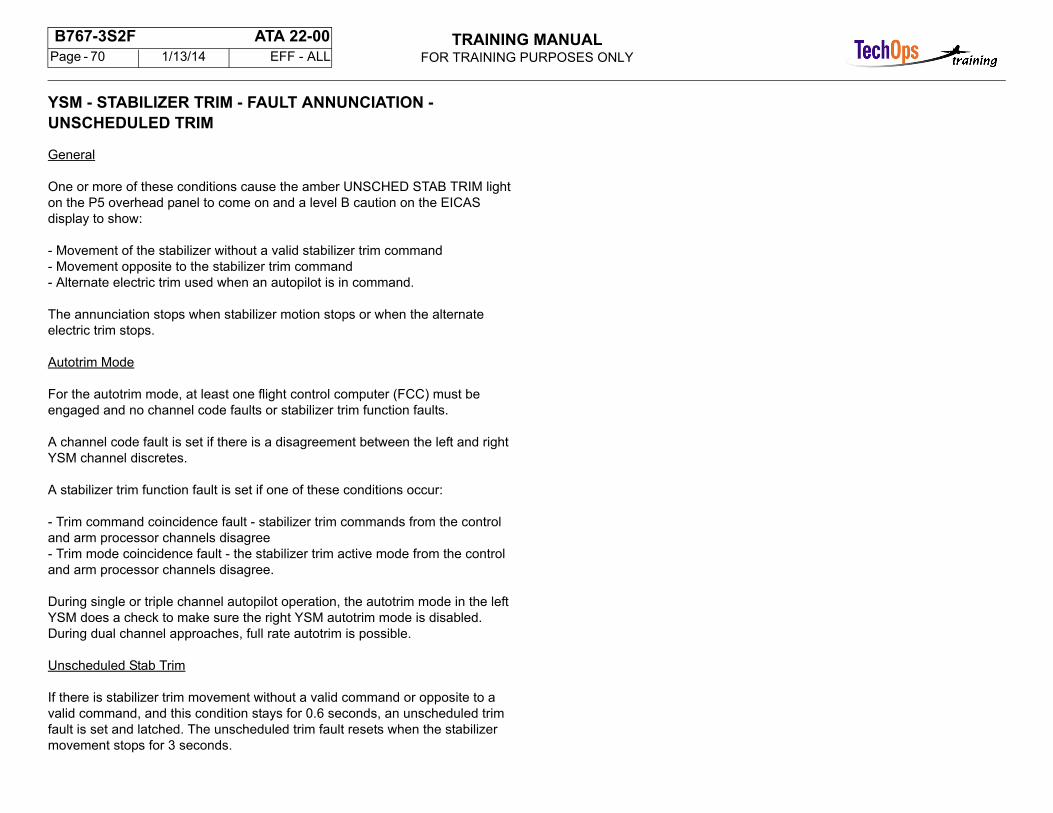
TRAINING MANUALFOR TRAINING PURPOSES ONLY
B767-3S2F ATA 22-00 Page - 70 1/13/14 EFF - ALL
YSM - STABILIZER TRIM - FAULT ANNUNCIATION - UNSCHEDULED TRIM
General
One or more of these conditions cause the amber UNSCHED STAB TRIM light on the P5 overhead panel to come on and a level B caution on the EICAS display to show:
- Movement of the stabilizer without a valid stabilizer trim command- Movement opposite to the stabilizer trim command- Alternate electric trim used when an autopilot is in command.
The annunciation stops when stabilizer motion stops or when the alternate electric trim stops.
Autotrim Mode
For the autotrim mode, at least one flight control computer (FCC) must be engaged and no channel code faults or stabilizer trim function faults.
A channel code fault is set if there is a disagreement between the left and right YSM channel discretes.
A stabilizer trim function fault is set if one of these conditions occur:
- Trim command coincidence fault - stabilizer trim commands from the control and arm processor channels disagree- Trim mode coincidence fault - the stabilizer trim active mode from the control and arm processor channels disagree.
During single or triple channel autopilot operation, the autotrim mode in the left YSM does a check to make sure the right YSM autotrim mode is disabled. During dual channel approaches, full rate autotrim is possible.
Unscheduled Stab Trim
If there is stabilizer trim movement without a valid command or opposite to a valid command, and this condition stays for 0.6 seconds, an unscheduled trimfault is set and latched. The unscheduled trim fault resets when the stabilizer movement stops for 3 seconds.
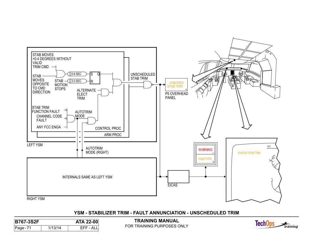
TRAINING MANUALFOR TRAINING PURPOSES ONLY
B767-3S2F ATA 22-00 Page - 71 1/13/14 EFF - ALL
TAT
UNSCHD STAB TRIMWARNING
CAUTION
P5 OVERHEADPANEL
EICAS
STAB TRIMUNSCHED
LEFT YSM
INTERNALS SAME AS LEFT YSM
UNSCHEDULED
STAB MOVES>0.4 DEGREES WITHOUT
STAB TRIM
VALIDTRIM CMD
STABMOVESOPPOSITETO CMDDIRECTION
RIGHT YSM
CONTROL PROC
ARM PROC
r
a
a
ANY FCC ENGA
CHANNEL CODEFAULT
STAB TRIMFUNCTION FAULT AUTOTRIM
MODE
AUTOTRIMMODE (RIGHT)
ALTERNATEELECTTRIM
S
R
Q0.6 SEC
STABMOTIONSTOPS
3.0 SEC
YSM - STABILIZER TRIM - FAULT ANNUNCIATION - UNSCHEDULED TRIM
TRAINING MANUALFOR TRAINING PURPOSES ONLY
B767-3S2F ATA 22-00 Page - 72 1/13/14 EFF - ALL
FLT CONT/HYD - GENERAL DESCRIPTION - FLIGHTCONTROLS
General
All flight control surfaces are moved by hydraulic power control actuators (PCAs). PCAs are controlled by mechanical linkage with manual, autopilot, and attitude inputs.
Manual Controls
A system of cables, quadrants, and rods provide manual control from the control wheel, control column, and rudder pedals. Manual control of the ailerons is helped by lateral central control actuators (LCCAs) which drive the mechanical systems in the wings. Manual inputs include artificial feel components to provide feel in the absence of aerodynamic feedback force.
Autopilot Controls
The autopilot system provides electrical commands to control servos which for ailerons are the LCCAs. The servos provide the mechanical control of the PCAs. The required position feedback information is by electrical signal from the servos.
Attitude Controls
Automatic attitude control is provided for yaw damping. Electrical commands to the servos result in mechanical motion of the PCA control linkage. Position feedback is also by electrical signal from the servos.
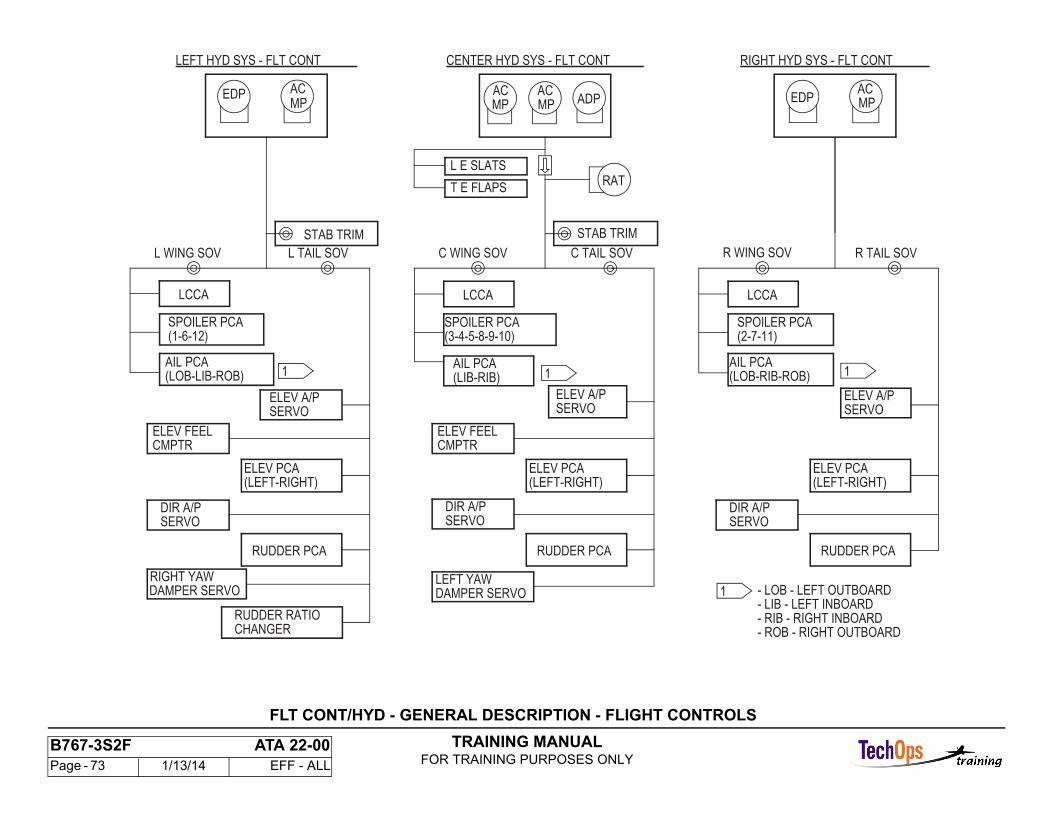
TRAINING MANUALFOR TRAINING PURPOSES ONLY
B767-3S2F ATA 22-00 Page - 73 1/13/14 EFF - ALL
STAB TRIM STAB TRIM
CHANGERRUDDER RATIO
DAMPER SERVOLEFT YAW
RUDDER PCA
SERVO
(1-6-12)
(LOB-LIB-ROB)
LCCA
ELEV A/P
AIL PCA
SPOILER PCA
L WING SOV L TAIL SOV
(LEFT-RIGHT)
(LIB-RIB)
(3-4-5-8-9-10)
SERVOELEV A/P
DIR A/PSERVO
ELEV FEELCMPTR
LCCA
C TAIL SOV
ELEV PCA
AIL PCA
SPOILER PCA
C WING SOV
(LOB-RIB-ROB)
(2-7-11)
SERVOELEV A/P
LCCA
R TAIL SOV
AIL PCA
SPOILER PCA
R WING SOV
RAT
ACEDPADP
ACACACEDP
RIGHT HYD SYS - FLT CONT
L E SLATS
T E FLAPS
CENTER HYD SYS - FLT CONTLEFT HYD SYS - FLT CONT
- ROB - RIGHT OUTBOARD- RIB - RIGHT INBOARD- LIB - LEFT INBOARD- LOB - LEFT OUTBOARD
MP MP MP MP
1 11
1DAMPER SERVORIGHT YAW
RUDDER PCA
(LEFT-RIGHT)
DIR A/PSERVO
ELEV FEELCMPTR
ELEV PCA
RUDDER PCA
(LEFT-RIGHT)
DIR A/PSERVO
ELEV PCA
FLT CONT/HYD - GENERAL DESCRIPTION - FLIGHT CONTROLS
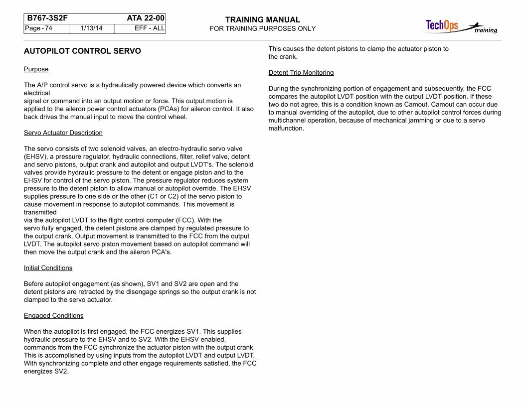
TRAINING MANUALFOR TRAINING PURPOSES ONLY
B767-3S2F ATA 22-00 Page - 74 1/13/14 EFF - ALL
AUTOPILOT CONTROL SERVO
Purpose
The A/P control servo is a hydraulically powered device which converts an electricalsignal or command into an output motion or force. This output motion isapplied to the aileron power control actuators (PCAs) for aileron control. It alsoback drives the manual input to move the control wheel.
Servo Actuator Description
The servo consists of two solenoid valves, an electro-hydraulic servo valve(EHSV), a pressure regulator, hydraulic connections, filter, relief valve, detentand servo pistons, output crank and autopilot and output LVDT's. The solenoidvalves provide hydraulic pressure to the detent or engage piston and to theEHSV for control of the servo piston. The pressure regulator reduces systempressure to the detent piston to allow manual or autopilot override. The EHSVsupplies pressure to one side or the other (C1 or C2) of the servo piston tocause movement in response to autopilot commands. This movement is transmittedvia the autopilot LVDT to the flight control computer (FCC). With theservo fully engaged, the detent pistons are clamped by regulated pressure tothe output crank. Output movement is transmitted to the FCC from the outputLVDT. The autopilot servo piston movement based on autopilot command willthen move the output crank and the aileron PCA's.
Initial Conditions
Before autopilot engagement (as shown), SV1 and SV2 are open and thedetent pistons are retracted by the disengage springs so the output crank is notclamped to the servo actuator.
Engaged Conditions
When the autopilot is first engaged, the FCC energizes SV1. This supplieshydraulic pressure to the EHSV and to SV2. With the EHSV enabled, commands from the FCC synchronize the actuator piston with the output crank. This is accomplished by using inputs from the autopilot LVDT and output LVDT. With synchronizing complete and other engage requirements satisfied, the FCCenergizes SV2.
This causes the detent pistons to clamp the actuator piston tothe crank.
Detent Trip Monitoring
During the synchronizing portion of engagement and subsequently, the FCCcompares the autopilot LVDT position with the output LVDT position. If thesetwo do not agree, this is a condition known as Camout. Camout can occur dueto manual overriding of the autopilot, due to other autopilot control forces duringmultichannel operation, because of mechanical jamming or due to a servo malfunction.
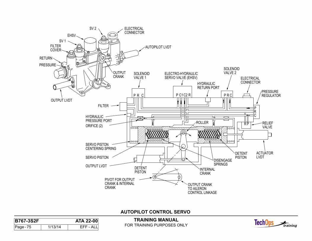
TRAINING MANUALFOR TRAINING PURPOSES ONLY
B767-3S2F ATA 22-00 Page - 75 1/13/14 EFF - ALL
LVDTACTUATOR
SERVO PISTON
PRESSURE PORT
CRANKOUTPUT
SV 2
EHSV
SV 1
PRESSURE
RETURN
VALVE 1SOLENOID
CRP
HYDRAULIC
FILTER
ORIFICE (2)
VALVE 2SOLENOID
CONNECTORELECTRICAL
OUTPUT LVDT
OUTPUT LVDT
PIVOT FOR OUTPUT
PISTON
ROLLER
DETENT
CRANKINTERNAL
SERVO VALVE (EHSV)
PR
CRP
RP RPC2C1 C
PISTONDETENT
VALVERELIEF
REGULATORPRESSURE
RETURN PORTHYDRAULIC
ELECTRO-HYDRAULIC
SPRINGSDISENGAGE
CENTERING SPRINGSERVO PISTON
AUTOPILOT LVDT
CONNECTORELECTRICAL
COVERFILTER
TO AILERONCONTROL LINKAGE
OUTPUT CRANKCRANKCRANK & INTERNAL
AUTOPILOT CONTROL SERVO
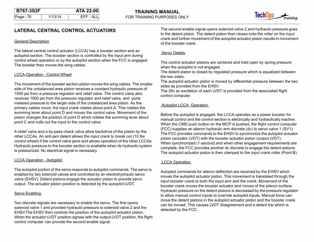
TRAINING MANUALFOR TRAINING PURPOSES ONLY
B767-3S2F ATA 22-00 Page - 76 1/13/14 EFF - ALL
LATERAL CENTRAL CONTROL ACTUATORS
General Description
The lateral central control actuator (LCCA) has a booster section and an autopilot section. The booster section is controlled by the input arm during control wheel operation or by the autopilot section when the FCC is engaged. The booster then moves the wing cables.
LCCA Operation - Control Wheel
The movement of the booster section piston moves the wing cables. The smaller side of the unbalanced area piston receives a constant hydraulic pressure of 1500 psi from a pressure regulator and relief valve. The control valve also receives 1500 psi from the pressure regulator and relief valve, and ports metered pressure to the larger side of the unbalanced area piston. As the primary cables move, the input crank rotates about point A. This rotates the summing lever about point D and moves the control valve. Movement of the piston changes the position of point D which rotates the summing lever about point C and nulls out the input to the control valve.
A relief valve and a by-pass check valve allow backdrive of the piston by the other LCCAs. An anti-jam detent allows the input crank to break out (10 lbs control wheel) if the control valve jams and allows operation of the other LCCAs. Hydraulic pressure to the booster section is available when its hydraulic system is pressurized. No electrical signal is necessary.
LCCA Operation - Autopilot
The autopilot portion of the servo responds to autopilot commands. The servo is enabled by two solenoid valves and controlled by an electrohydraulic servo valve (EHSV). Detent pistons engage the actuator piston to provide servo output. The actuator piston position is detected by the autopilot LVDT.
Servo Enabling
Two discrete signals are necessary to enable the servo. The first opens solenoid valve 1 and provides hydraulic pressure to solenoid valve 2 and the EHSV.The EHSV then controls the position of the autopilot actuator piston. When the actuator LVDT position agrees with the output LVDT position, the flight control computer can provide the second enable signal.
The second enable signal opens solenoid valve 2 and hydraulic pressure goes to the detent piston. The detent piston then closes onto the roller on the input crank and further movement of the autopilot actuator piston results in movement of the booster crank.
Servo Details
The control actuator pistons are centered and held open by spring pressure when the autopilot is not engaged.The detent piston is closed by regulated pressure which is equalized between the two sides.The autopilot actuator piston is moved by differential pressure between the two sides as provided from the EHSV.The 26v ac excitation of each LVDT is provided from the associated flight control computer.
Autopilot LCCA Operation
Before the autopilot is engaged, the LCCA operates as a power booster for manual control and the control section is electrically and hydraulically inactive. When the CMD push button on the MCP is pushed, the flight control computer (FCC) supplies an aileron hydraulic arm discrete (dc) to servo valve 1 (SV1).The FCC provides commands to the EHSV to synchronize the autopilot actuator piston (actuator LVDT) with the booster actuator piston (output LVDT).When synchronized (1 second) and when other engagement requirements are complete, the FCC provides another dc discrete to engage the detent pistons. The autopilot actuator piston is then clamped to the input crank roller (Point B).
LCCA Operation
Autopilot commands for aileron deflection are received by the EHSV which moves the autopilot actuator piston. This movement is translated through the input booster crank to both the input arm and the crank. Movement of the booster crank moves the booster actuator and moves of the aileron surface.Hydraulic pressure on the detent pistons is decreased by the pressure regulator to allow manual control inputs to override autopilot inputs. Manual force can move the detent pistons in the autopilot actuator piston and the booster crank can be moved. This causes LVDT disagreement and a detent trip which is detected by the FCC.
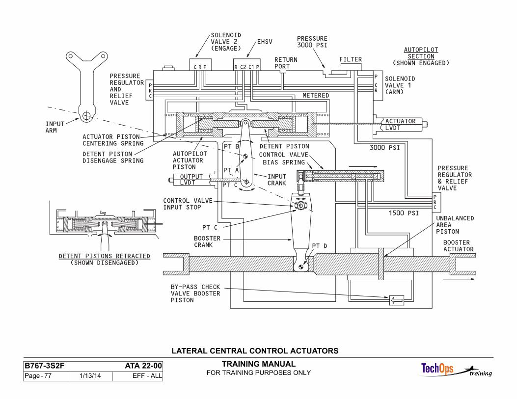
TRAINING MANUALFOR TRAINING PURPOSES ONLY
B767-3S2F ATA 22-00 Page - 77 1/13/14 EFF - ALL
LATERAL CENTRAL CONTROL ACTUATORS
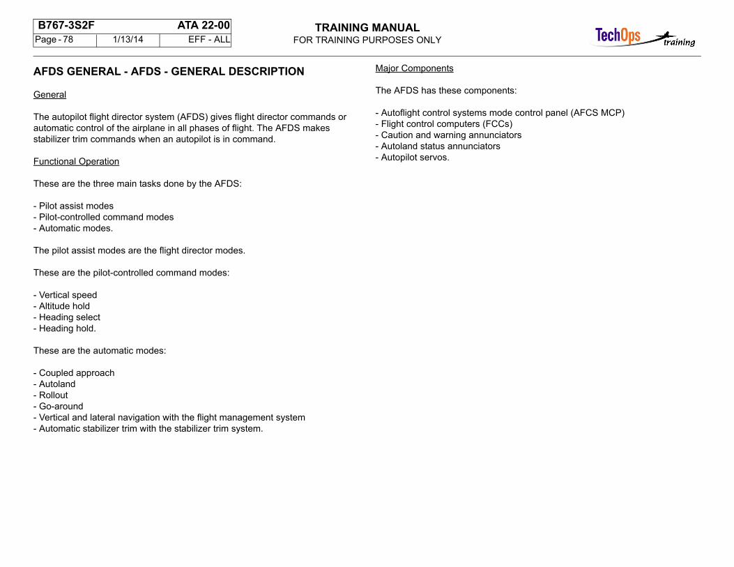
TRAINING MANUALFOR TRAINING PURPOSES ONLY
B767-3S2F ATA 22-00 Page - 78 1/13/14 EFF - ALL
AFDS GENERAL - AFDS - GENERAL DESCRIPTION
General
The autopilot flight director system (AFDS) gives flight director commands or automatic control of the airplane in all phases of flight. The AFDS makesstabilizer trim commands when an autopilot is in command.
Functional Operation
These are the three main tasks done by the AFDS:
- Pilot assist modes- Pilot-controlled command modes- Automatic modes.
The pilot assist modes are the flight director modes.
These are the pilot-controlled command modes:
- Vertical speed- Altitude hold- Heading select- Heading hold.
These are the automatic modes:
- Coupled approach- Autoland- Rollout- Go-around- Vertical and lateral navigation with the flight management system- Automatic stabilizer trim with the stabilizer trim system.
Major Components
The AFDS has these components:
- Autoflight control systems mode control panel (AFCS MCP)- Flight control computers (FCCs)- Caution and warning annunciators- Autoland status annunciators- Autopilot servos.
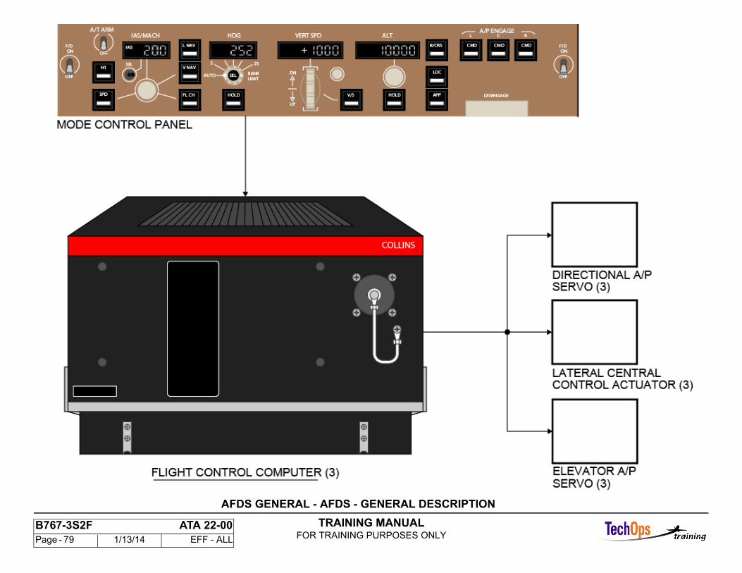
TRAINING MANUALFOR TRAINING PURPOSES ONLY
B767-3S2F ATA 22-00 Page - 79 1/13/14 EFF - ALL
AFDS GENERAL - AFDS - GENERAL DESCRIPTION
TRAINING MANUALFOR TRAINING PURPOSES ONLY
B767-3S2F ATA 22-00 Page - 80 1/13/14 EFF - ALL
AUTOPILOT FLIGHT DIRECTOR SYSTEM
General
The autopilot and flight director system (AFDS) provides automatic guidanceand control of the airplane ailerons, elevators, and, for autoland, the rudder. Italso provides the guidance processing for the flight director displays. Engagement and mode selection of the autopilot and flight director are accomplished through the AFCS mode control panel.
Annunciation and Display
Each attitude director indicator (ADI) portion of the PFD displays flight directorand AFDS commands on the flight mode annunciator (FMA). The FMAidentifies AFDS status, roll/pitch arm and engaged modes. The autoland statusannunciators identify the system capability and limitation status for autolandoperations. The AFCS mode control panel has mode selector switch annunciation and reference readouts. A red A/P DISC light and an amber AUTOPILOT caution light gives visual alerts for A/P warnings and cautions.
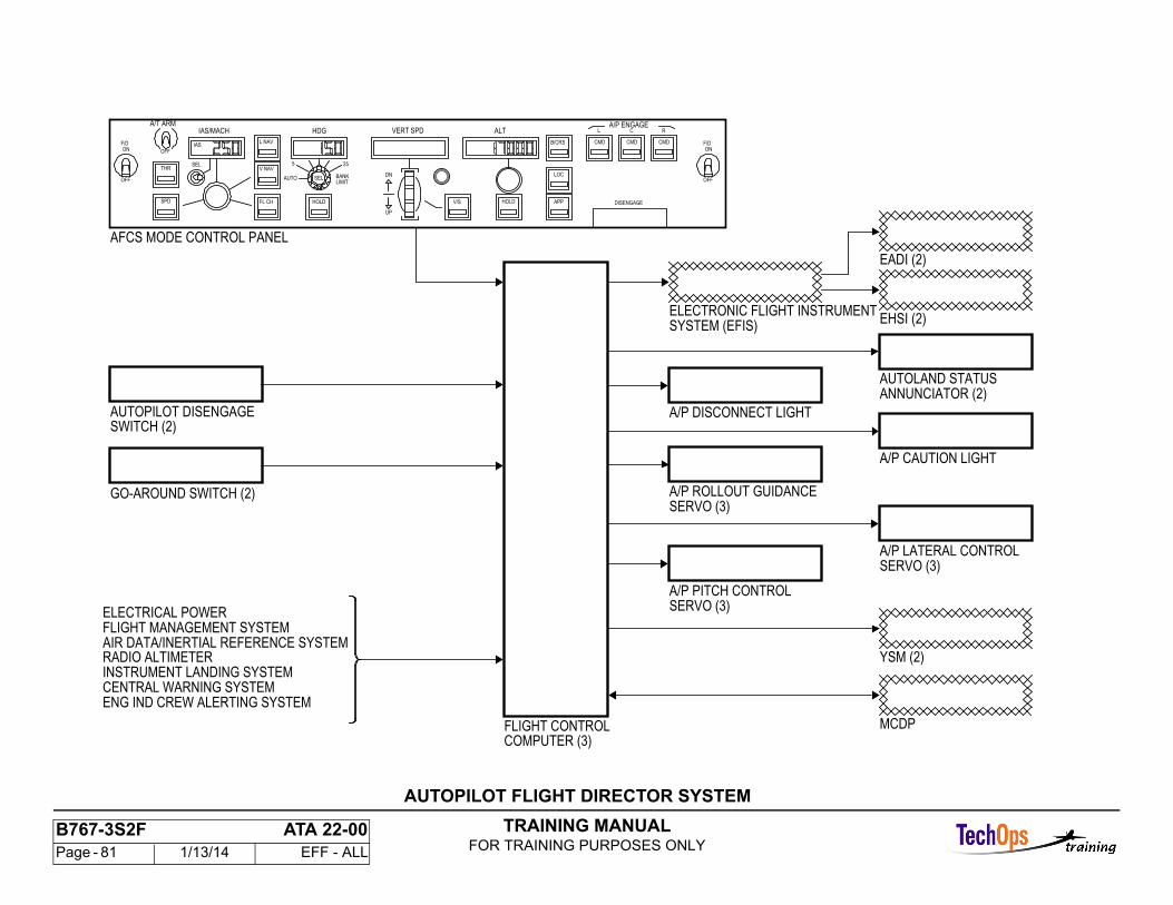
TRAINING MANUALFOR TRAINING PURPOSES ONLY
B767-3S2F ATA 22-00 Page - 81 1/13/14 EFF - ALL
A/P LATERAL CONTROL
A/P ROLLOUT GUIDANCE
A/P PITCH CONTROL
INSTRUMENT LANDING SYSTEM
AIR DATA/INERTIAL REFERENCE SYSTEMFLIGHT MANAGEMENT SYSTEM
AFCS MODE CONTROL PANEL
MCDP
AUTOLAND STATUS
ENG IND CREW ALERTING SYSTEMCENTRAL WARNING SYSTEM
RADIO ALTIMETER
ELECTRICAL POWER
GO-AROUND SWITCH (2)
AUTOPILOT DISENGAGE
FLIGHT CONTROLCOMPUTER (3)
SWITCH (2)
ELECTRONIC FLIGHT INSTRUMENTSYSTEM (EFIS)
EADI (2)
EHSI (2)
YSM (2)
ANNUNCIATOR (2)
A/P DISCONNECT LIGHT
A/P CAUTION LIGHT
SERVO (3)
SERVO (3)
SERVO (3)
IAS
255
AUTO BANKLIMIT
F/DON
OFF
R
CMD
C
CMD
L
DISENGAGE
ALT
APP
LOC
B/CRS
HOLDV/S
VERT SPDHDGIAS/MACH
UP
DN
HOLDFL CH
V NAV
L NAV
SEL
OFF
A/T ARM
SPD
OFF
F/DON
A/P ENGAGE
CMD
SEL
THR
AUTOPILOT FLIGHT DIRECTOR SYSTEM
TRAINING MANUALFOR TRAINING PURPOSES ONLY
B767-3S2F ATA 22-00 Page - 82 1/13/14 EFF - ALL
AFDS GENERAL - BLOCK DIAGRAM
General
This block diagram shows the AFDS hardware configuration by function.
Pilot Control Function
The AFCS mode control panel gives the primary interface between the pilots and the AFDS. The thrust management system also uses the mode control panel. Pilot inputs have a direct interface with the flight control computers.
I/O, Calculation, and Monitor Functions
The flight control computers (FCCs) are the primary calculation units of the AFDS. These are the functions of the FCCs:
- Control law calculation- Sensor interface and management- Control system interface- Engage and disengage- Monitor- Annunciation management.
Navigation Sensors
The avionics navigation sensors supply inertial, atmospheric, and ground reference feedback data to the AFDS. The navigation sensors necessary for autoland are triple redundant. The other navigation sensors are dualredundant.
Airplane Configuration Sensors
The airplane configuration sensors give the necessary data to make modifications in the control in relation to the airplane flight properties.
Flight Controls Interface
The autopilot servos give the mechanical power to operate the surface power control actuators (PCAs). The autopilot gives stabilizer trim with the yawdamper/stabilizer trim modules (YSMs) and the stabilizer trim control modules (STCMs).
Electronic Flight Instrument System
The EADI is the primary display for the AFDS and shows these functions:
- Flight director commands- Flight mode annunciation- Status.
The EHSI shows the selected heading index.
Maintenance Function
The maintenance control and display panel (MCDP) gives the maintenance function for the AFDS.
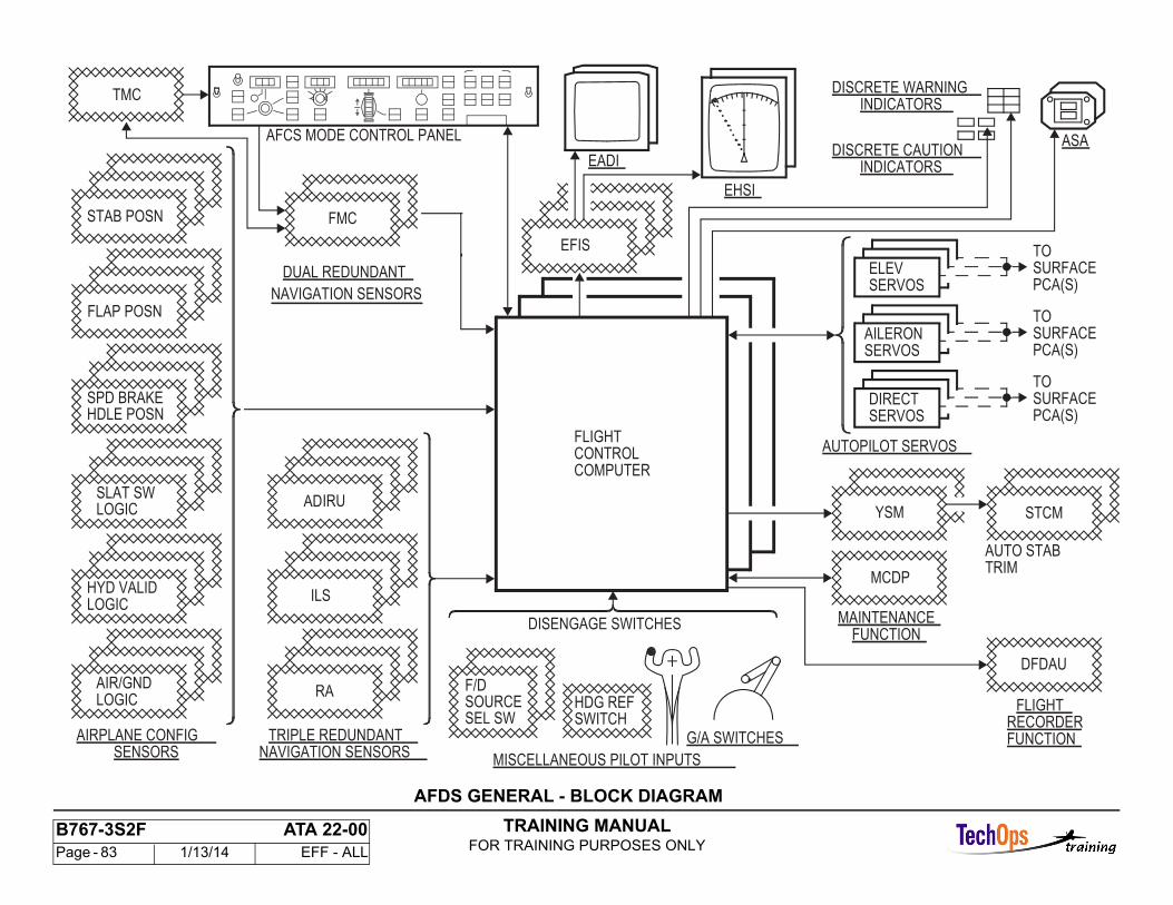
TRAINING MANUALFOR TRAINING PURPOSES ONLY
B767-3S2F ATA 22-00 Page - 83 1/13/14 EFF - ALL
FLIGHTCONTROLCOMPUTER
TOSURFACEPCA(S)
AUTOPILOT SERVOS
DISENGAGE SWITCHES
G/A SWITCHES
AFCS MODE CONTROL PANEL
EADI
EHSI
ASA
MISCELLANEOUS PILOT INPUTS
F/DSOURCE
SERVOSDIRECT
TOSURFACEPCA(S)SERVOS
AILERON
TOSURFACEPCA(S)SERVOS
ELEV
EFIS
SEL SWHDG REFSWITCH
DISCRETE WARNINGINDICATORS
DISCRETE CAUTIONINDICATORS
DFDAU
FLIGHTRECORDERFUNCTIONTRIPLE REDUNDANT
NAVIGATION SENSORS
MAINTENANCEFUNCTION
AUTO STAB
TMC
DUAL REDUNDANT
NAVIGATION SENSORS
AIRPLANE CONFIGSENSORS
AIR/GNDLOGIC
HYD VALID
SLAT SWLOGIC
SPD BRAKEHDLE POSN
FLAP POSN
STAB POSN
RA
ILS
IRU
FMC
YSM STCM
MCDPTRIM
LOGIC
AD
AFDS GENERAL - BLOCK DIAGRAM
TRAINING MANUALFOR TRAINING PURPOSES ONLY
B767-3S2F ATA 22-00 Page - 84 1/13/14 EFF - ALL
AFDS GENERAL - COMPONENT LOCATION
Flight Compartment Components
The flight compartment components for AFDS operation give these functions:
- Control- Flight director display and source selection- Annunciation- Warning and caution alerts- Autopilot disconnect- Go-around functions.
Airborne Data Loader
The airborne data loader (ADL) is a general purpose disk drive unit that does uploads and downloads of computer programs and data. The ADL connects to the airplane computers by ARINC 429 data buses. Connection to LRUs is at the data loader control panel.
Main Equipment Center Components
The FCCs are in the main equipment center.
Autopilot Servos
The three lateral central control actuators are in the wing roots with the left and right units on the left side and the center unit on the right side.
The three elevator autopilot servos are in the tail aft of the stabilizer.
The three directional autopilot servos are in the vertical stabilizer.
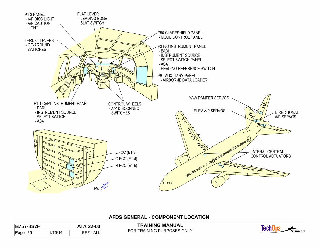
TRAINING MANUALFOR TRAINING PURPOSES ONLY
B767-3S2F ATA 22-00 Page - 85 1/13/14 EFF - ALL
L FCC (E1-3)
R FCC (E1-5)
C FCC (E1-4)
- MODE CONTROL PANELP55 GLARESHIELD PANEL
- EADI
SELECT SWITCH PANEL - INSTRUMENT SOURCE
P3 F/O INSTRUMENT PANEL
- HEADING REFERENCE SWITCH - ASA
SWITCHES - A/P DISCONNECT
SLAT SWITCH - LEADING EDGEFLAP LEVER
- A/P DISC LIGHT
CONTROL WHEELS
- ASA SELECT SWITCH - INSTRUMENT SOURCE - EADIP1-1 CAPT INSTRUMENT PANEL
LIGHT - A/P CAUTION
P1-3 PANEL
A/P SERVOS
CONTROL ACTUATORSLATERAL CENTRAL
DIRECTIONAL
YAW DAMPER SERVOS
ELEV A/P SERVOS
P61 AUXILIARY PANEL- AIRBORNE DATA LOADER
FWD
- GO-AROUND THRUST LEVERS
SWITCHES
AFDS GENERAL - COMPONENT LOCATION
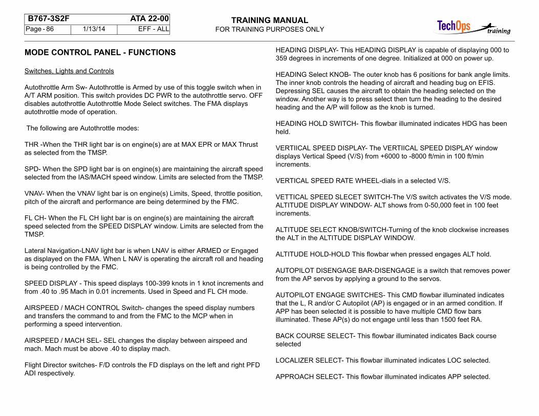
TRAINING MANUALFOR TRAINING PURPOSES ONLY
B767-3S2F ATA 22-00 Page - 86 1/13/14 EFF - ALL
MODE CONTROL PANEL - FUNCTIONS
Switches, Lights and Controls
Autothrottle Arm Sw- Autothrottle is Armed by use of this toggle switch when inA/T ARM position. This switch provides DC PWR to the autothrottle servo. OFFdisables autothrottle Autothrottle Mode Select switches. The FMA displays autothrottle mode of operation.
The following are Autothrottle modes:
THR -When the THR light bar is on engine(s) are at MAX EPR or MAX Thrustas selected from the TMSP.
SPD- When the SPD light bar is on engine(s) are maintaining the aircraft speedselected from the IAS/MACH speed window. Limits are selected from the TMSP.
VNAV- When the VNAV light bar is on engine(s) Limits, Speed, throttle position,pitch of the aircraft and performance are being determined by the FMC.
FL CH- When the FL CH light bar is on engine(s) are maintaining the aircraftspeed selected from the SPEED DISPLAY window. Limits are selected from theTMSP.
Lateral Navigation-LNAV light bar is when LNAV is either ARMED or Engagedas displayed on the FMA. When L NAV is operating the aircraft roll and headingis being controlled by the FMC.
SPEED DISPLAY - This speed displays 100-399 knots in 1 knot increments andfrom .40 to .95 Mach in 0.01 increments. Used in Speed and FL CH mode.
AIRSPEED / MACH CONTROL Switch- changes the speed display numbersand transfers the command to and from the FMC to the MCP when inperforming a speed intervention.
AIRSPEED / MACH SEL- SEL changes the display between airspeed andmach. Mach must be above .40 to display mach.
Flight Director switches- F/D controls the FD displays on the left and right PFDADI respectively.
HEADING DISPLAY- This HEADING DISPLAY is capable of displaying 000 to359 degrees in increments of one degree. Initialized at 000 on power up.
HEADING Select KNOB- The outer knob has 6 positions for bank angle limits.The inner knob controls the heading of aircraft and heading bug on EFIS.Depressing SEL causes the aircraft to obtain the heading selected on thewindow. Another way is to press select then turn the heading to the desiredheading and the A/P will follow as the knob is turned.
HEADING HOLD SWITCH- This flowbar illuminated indicates HDG has beenheld.
VERTIICAL SPEED DISPLAY- The VERTIICAL SPEED DISPLAY windowdisplays Vertical Speed (V/S) from +6000 to -8000 ft/min in 100 ft/minincrements.
VERTICAL SPEED RATE WHEEL-dials in a selected V/S.
VETTICAL SPEED SLECET SWITCH-The V/S switch activates the V/S mode.ALTITUDE DISPLAY WINDOW- ALT shows from 0-50,000 feet in 100 feetincrements.
ALTITUDE SELECT KNOB/SWITCH-Turning of the knob clockwise increasesthe ALT in the ALTITUDE DISPLAY WINDOW.
ALTITUDE HOLD-HOLD This flowbar when pressed engages ALT hold.
AUTOPILOT DISENGAGE BAR-DISENGAGE is a switch that removes powerfrom the AP servos by applying a ground to the servos.
AUTOPILOT ENGAGE SWITCHES- This CMD flowbar illuminated indicatesthat the L, R and/or C Autopilot (AP) is engaged or in an armed condition. IfAPP has been selected it is possible to have multiple CMD flow barsilluminated. These AP(s) do not engage until less than 1500 feet RA.
BACK COURSE SELECT- This flowbar illuminated indicates Back courseselected
LOCALIZER SELECT- This flowbar illuminated indicates LOC selected.
APPROACH SELECT- This flowbar illuminated indicates APP selected.
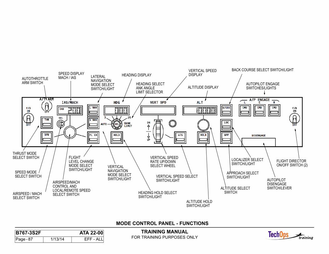
TRAINING MANUALFOR TRAINING PURPOSES ONLY
B767-3S2F ATA 22-00 Page - 87 1/13/14 EFF - ALL
ARM SWITCHAUTOTHROTTLE
SWITCHES/LIGHTSAUTOPILOT ENGAGE
HEADING DISPLAY
ALTITUDE DISPLAY
SELECT SWITCHTHRUST MODE
SELECT SWITCHAIRSPEED / MACH
DISPLAYVERTICAL SPEED
MACH / IASSPEED DISPLAY
DISENGAGEAUTOPILOT
ON/OFF SWITCH (2)FLIGHT DIRECTOR
SELECT SWITCHSPEED MODE
AIRSPEED/MACH
LOCAL/REMOTE SPEEDCONTROL AND
SELECT SWITCH
VERTICAL
MODE SELECTSWITCH/LIGHT
NAVIGATION
FLIGHT
MODE SELECTSWITCH/LIGHT
LEVEL CHANGE
LATERAL
MODE SELECTSWITCH/LIGHT
NAVIGATION
SWITCH/LEVER
RATE UP/DOWNVERTICAL SPEED
SELECT WHEEL
BACK COURSE SELECT SWITCH/LIGHT
LOCALIZER SELECTSWITCH/LIGHT
APPROACH SELECTSWITCH/LIGHT
ALTITUDE HOLDSWITCH/LIGHT
VERTICAL SPEED SELECTSWITCH/LIGHT
HEADING HOLD SELECTSWITCH/LIGHT
HEADING SELECTANK ANGLELIMIT SELECTOR
ALTITUDE SELECT SWITCH
MODE CONTROL PANEL - FUNCTIONS
TRAINING MANUALFOR TRAINING PURPOSES ONLY
B767-3S2F ATA 22-00 Page - 88 1/13/14 EFF - ALL
AFDS - ANNUNCIATION AND WARNING - GENERAL DESCRIPTION
Description
All three FCCs send this data to each EFIS symbol generator:
- Mode status- Flight director commands- Heading cursor.
Mode status and flight director commands show on the EADI. The heading cursor shows on the EHSI. The EFIS symbol generators control the data source selection. Autoland status LAND 3 or LAND 2 shows in green on theAutoland Status Annunciator or ASA.
The autopilot disengage warning light signal from each flight control computer goes to the panel light and the warning electronics unit. The warning electronics unit causes the captain and first officer master warning lights to come on and supplies the two-tone siren aural warning.
The autopilot caution light signal from each flight control computer goes to the panel light and to each EICAS computer. The EICAS computer causes the captain and first officer master caution lights to come on andgives a signal to the warning electronics unit. The warning electronics unit supplies the level B caution aural.
Autopilot disengage and autopilot caution message signals from each flight control computer goes to each EICAS computer. The EICAS computer shows the necessary level A or level B message on the applicable display unit.
Each flight control computer supplies autopilot multichannel operation status signals during an approach mode to the captain and first officer autoland statusannunciators. The autoland status annunciators give four messages for the different multi-channel operation conditions.
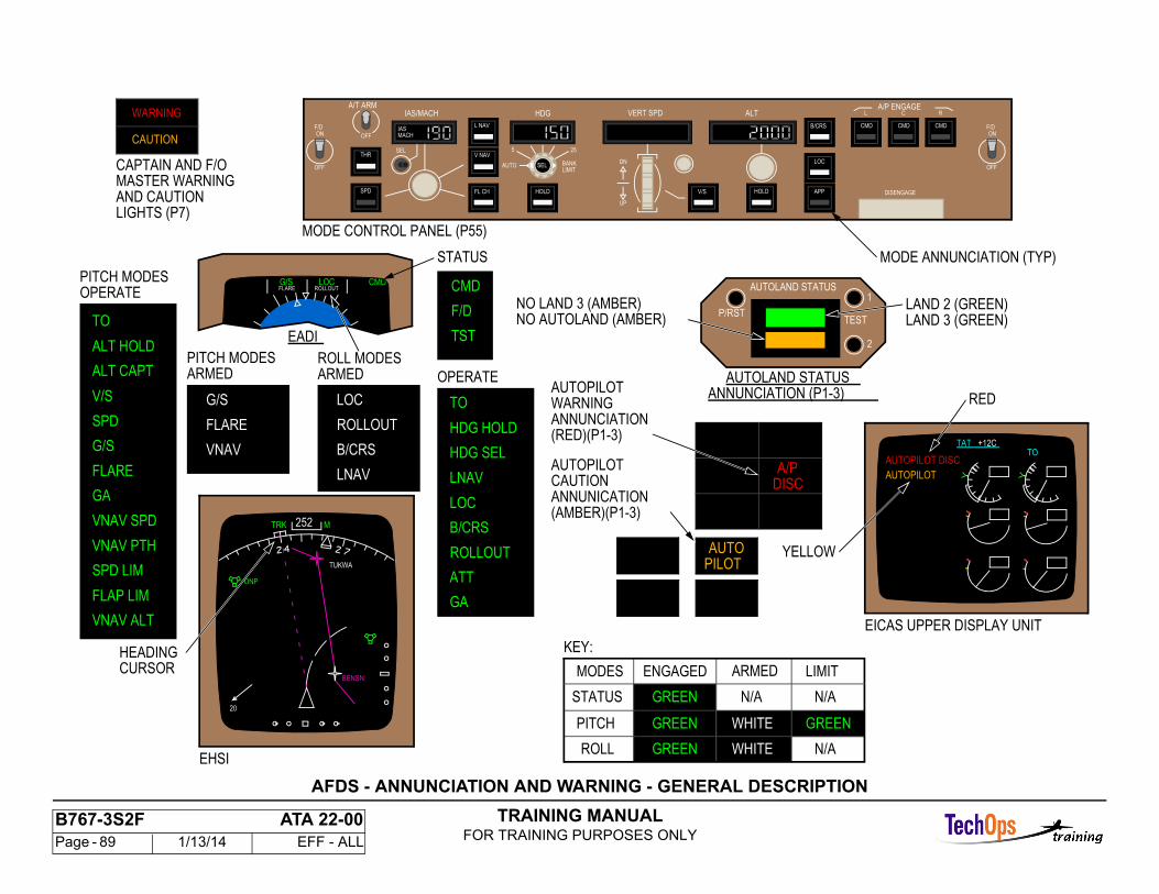
TRAINING MANUALFOR TRAINING PURPOSES ONLY
B767-3S2F ATA 22-00 Page - 89 1/13/14 EFF - ALL
EADI
CMDLOCG/SROLLOUTFLARE CMD
F/D
TST
ARMED OPERATEARMEDROLL MODESPITCH MODES
CAUTION
WARNING
FLARE
VNAV
G/S
ROLLOUT
B/CRS
LOC
LNAV
HDG HOLD
HDG SEL
TO
LOC
LNAV
B/CRS
ROLLOUT
ATT
NO AUTOLAND (AMBER)NO LAND 3 (AMBER)
EICAS UPPER DISPLAY UNIT
YELLOW
RED
LAND 3 (GREEN)LAND 2 (GREEN)
ANNUNCIATION (P1-3)AUTOLAND STATUS
(AMBER)(P1-3)ANNUNICATIONCAUTIONAUTOPILOT
(RED)(P1-3)ANNUNCIATIONWARNINGAUTOPILOT
TEST
2
1
P/RST
AUTOLAND STATUS
PILOTAUTO
DISCA/P
N/AGREEN
N/ASTATUS
ARMED
KEY:
ROLL
WHITEPITCH
N/AGREEN
LIMITENGAGEDMODES
GREEN
WHITE
GREEN
AUTOPILOT
AUTOPILOT DISCTO
TAT
LIGHTS (P7)
MASTER WARNINGAND CAUTION
CAPTAIN AND F/O
+12C
STATUS
GA
PITCH MODESOPERATE
FLAP LIM
VNAV PTH
VNAV SPD
ALT CAPT
ALT HOLD
FLARE
SPD LIM
TO
GA
SPD
V/S
G/S
VNAV ALT
OFF
F/DON
255
AUTO BANKLIMIT
MACHIAS F/D
ON
OFF
R
CMD
C
CMD
L
DISENGAGE
ALT
APP
LOC
B/CRS
HOLDV/S
VERT SPDHDGIAS/MACH
UP
DN
HOLDFL CH
V NAV
L NAV
SEL
OFF
A/T ARM
SPD
THR
A/P ENGAGE
CMD
SEL
MODE ANNUNCIATION (TYP)
MODE CONTROL PANEL (P55)
252
ONP
TUKWA
BENSN
20
TRK M
CURSORHEADING
EHSI
AFDS - ANNUNCIATION AND WARNING - GENERAL DESCRIPTION
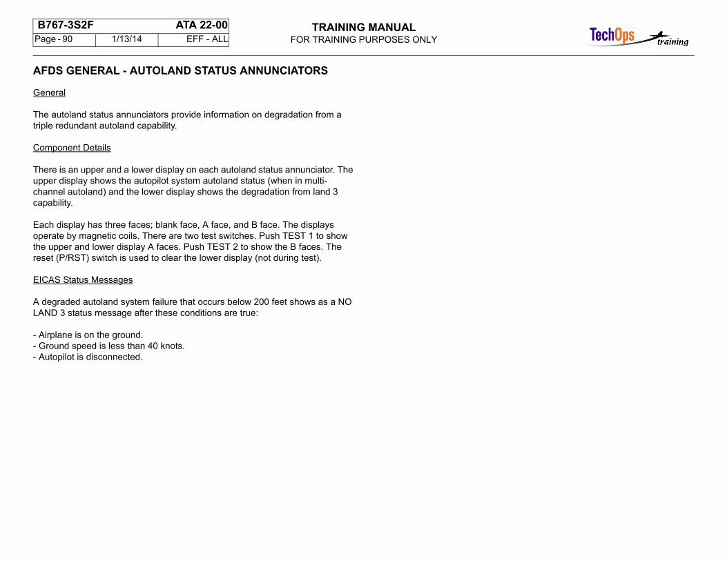
TRAINING MANUALFOR TRAINING PURPOSES ONLY
B767-3S2F ATA 22-00 Page - 90 1/13/14 EFF - ALL
AFDS GENERAL - AUTOLAND STATUS ANNUNCIATORS
General
The autoland status annunciators provide information on degradation from a triple redundant autoland capability.
Component Details
There is an upper and a lower display on each autoland status annunciator. The upper display shows the autopilot system autoland status (when in multi-channel autoland) and the lower display shows the degradation from land 3 capability.
Each display has three faces; blank face, A face, and B face. The displays operate by magnetic coils. There are two test switches. Push TEST 1 to show the upper and lower display A faces. Push TEST 2 to show the B faces. The reset (P/RST) switch is used to clear the lower display (not during test).
EICAS Status Messages
A degraded autoland system failure that occurs below 200 feet shows as a NO LAND 3 status message after these conditions are true:
- Airplane is on the ground.- Ground speed is less than 40 knots.- Autopilot is disconnected.
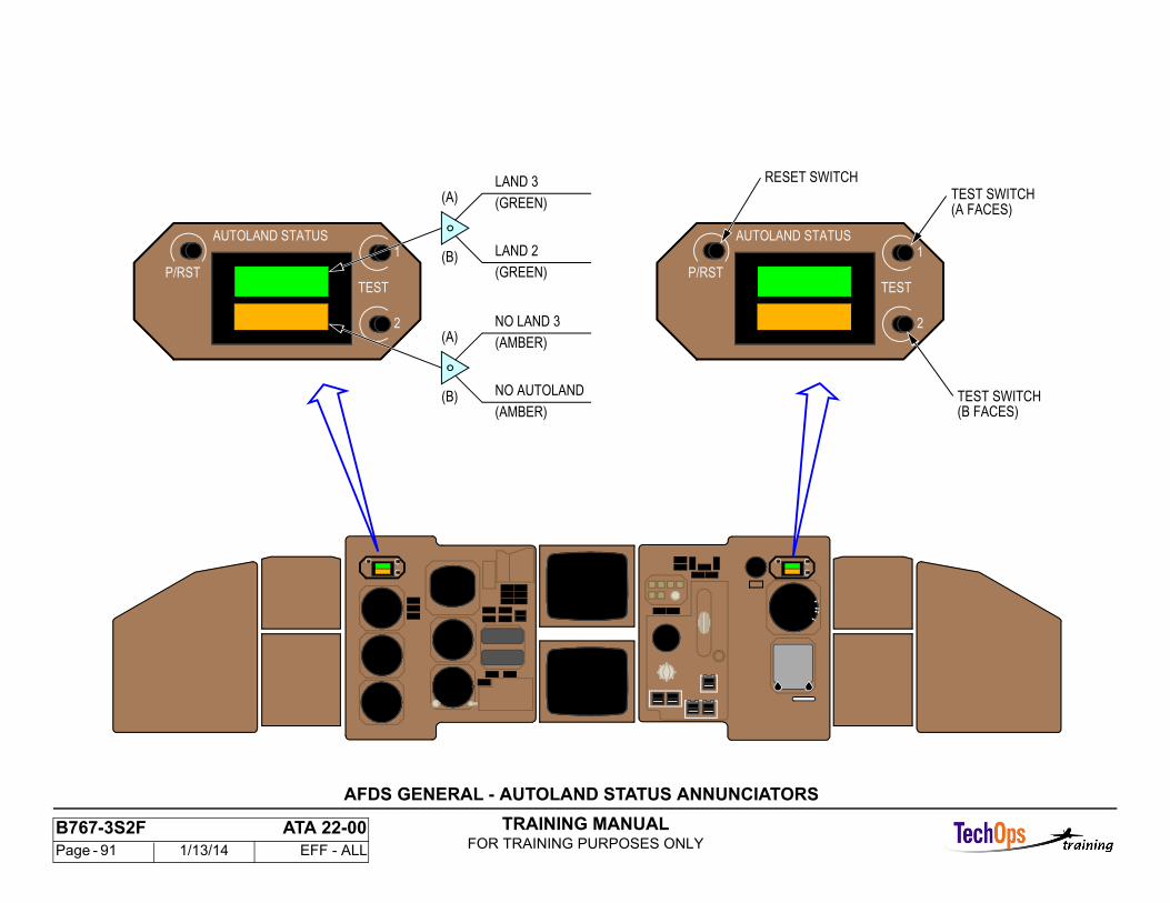
TRAINING MANUALFOR TRAINING PURPOSES ONLY
B767-3S2F ATA 22-00 Page - 91 1/13/14 EFF - ALL
2
1
TESTP/RST
AUTOLAND STATUS
2
1
TESTP/RST
AUTOLAND STATUS
(B FACES)TEST SWITCH
(A FACES)TEST SWITCH
RESET SWITCH
NO LAND 3
(AMBER)
NO AUTOLAND
(AMBER)
(GREEN)
LAND 2
(GREEN)
LAND 3
(B)
(A)
(B)
(A)
AFDS GENERAL - AUTOLAND STATUS ANNUNCIATORS
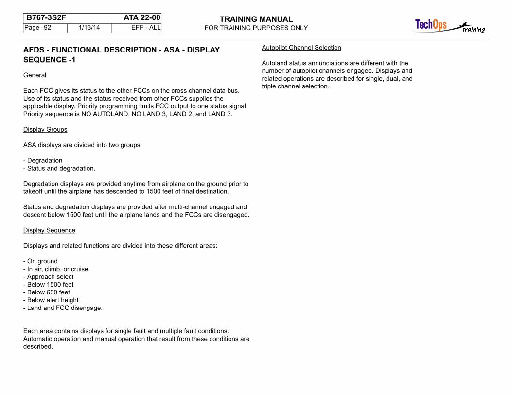
TRAINING MANUALFOR TRAINING PURPOSES ONLY
B767-3S2F ATA 22-00 Page - 92 1/13/14 EFF - ALL
AFDS - FUNCTIONAL DESCRIPTION - ASA - DISPLAY SEQUENCE -1
General
Each FCC gives its status to the other FCCs on the cross channel data bus.Use of its status and the status received from other FCCs supplies the applicable display. Priority programming limits FCC output to one status signal. Priority sequence is NO AUTOLAND, NO LAND 3, LAND 2, and LAND 3.
Display Groups
ASA displays are divided into two groups:
- Degradation- Status and degradation.
Degradation displays are provided anytime from airplane on the ground prior to takeoff until the airplane has descended to 1500 feet of final destination.
Status and degradation displays are provided after multi-channel engaged and descent below 1500 feet until the airplane lands and the FCCs are disengaged.
Display Sequence
Displays and related functions are divided into these different areas:
- On ground- In air, climb, or cruise- Approach select- Below 1500 feet- Below 600 feet- Below alert height- Land and FCC disengage.
Each area contains displays for single fault and multiple fault conditions. Automatic operation and manual operation that result from these conditions aredescribed.
Autopilot Channel Selection
Autoland status annunciations are different with thenumber of autopilot channels engaged. Displays andrelated operations are described for single, dual, andtriple channel selection.
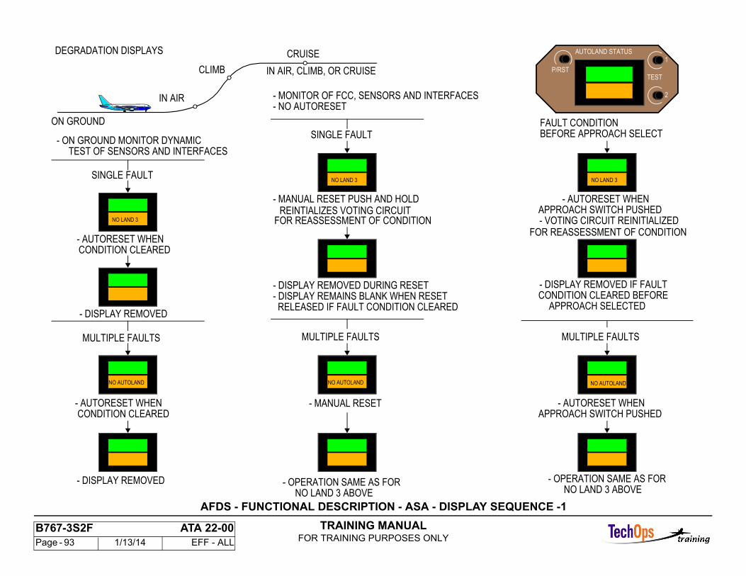
TRAINING MANUALFOR TRAINING PURPOSES ONLY
B767-3S2F ATA 22-00 Page - 93 1/13/14 EFF - ALL
DEGRADATION DISPLAYS
ON GROUND
SINGLE FAULT
- DISPLAY REMOVED
MULTIPLE FAULTS
IN AIR
CLIMB
CRUISE
IN AIR, CLIMB, OR CRUISE
- MONITOR OF FCC, SENSORS AND INTERFACES
- DISPLAY REMOVED DURING RESET- DISPLAY REMAINS BLANK WHEN RESET
RELEASED IF FAULT CONDITION CLEARED
- MANUAL RESET PUSH AND HOLDREINTIALIZES VOTING CIRCUIT
FOR REASSESSMENT OF CONDITION
- NO AUTORESET
MULTIPLE FAULTS
- MANUAL RESET
- OPERATION SAME AS FORNO LAND 3 ABOVE
- DISPLAY REMOVED
- AUTORESET WHEN
- ON GROUND MONITOR DYNAMICTEST OF SENSORS AND INTERFACES
- AUTORESET WHEN
CONDITION CLEARED
FAULT CONDITIONBEFORE APPROACH SELECT
- AUTORESET WHENAPPROACH SWITCH PUSHED- VOTING CIRCUIT REINITIALIZED
FOR REASSESSMENT OF CONDITION
- DISPLAY REMOVED IF FAULTCONDITION CLEARED BEFORE
APPROACH SELECTED
- AUTORESET WHENAPPROACH SWITCH PUSHED
- OPERATION SAME AS FORNO LAND 3 ABOVE
MULTIPLE FAULTS
CONDITION CLEARED
SINGLE FAULT
2
1
TESTP/RST
AUTOLAND STATUS
NO LAND 3
NO AUTOLAND
NO LAND 3
NO AUTOLAND NO AUTOLAND
NO LAND 3
AFDS - FUNCTIONAL DESCRIPTION - ASA - DISPLAY SEQUENCE -1

TRAINING MANUALFOR TRAINING PURPOSES ONLY
B767-3S2F ATA 22-00 Page - 94 1/13/14 EFF - ALL
AFDS - FUNCTIONAL DESCRIPTION - ASA - DISPLAY SEQUENCE - 2
General
This page continues the autoland status annunciatordisplay sequence.
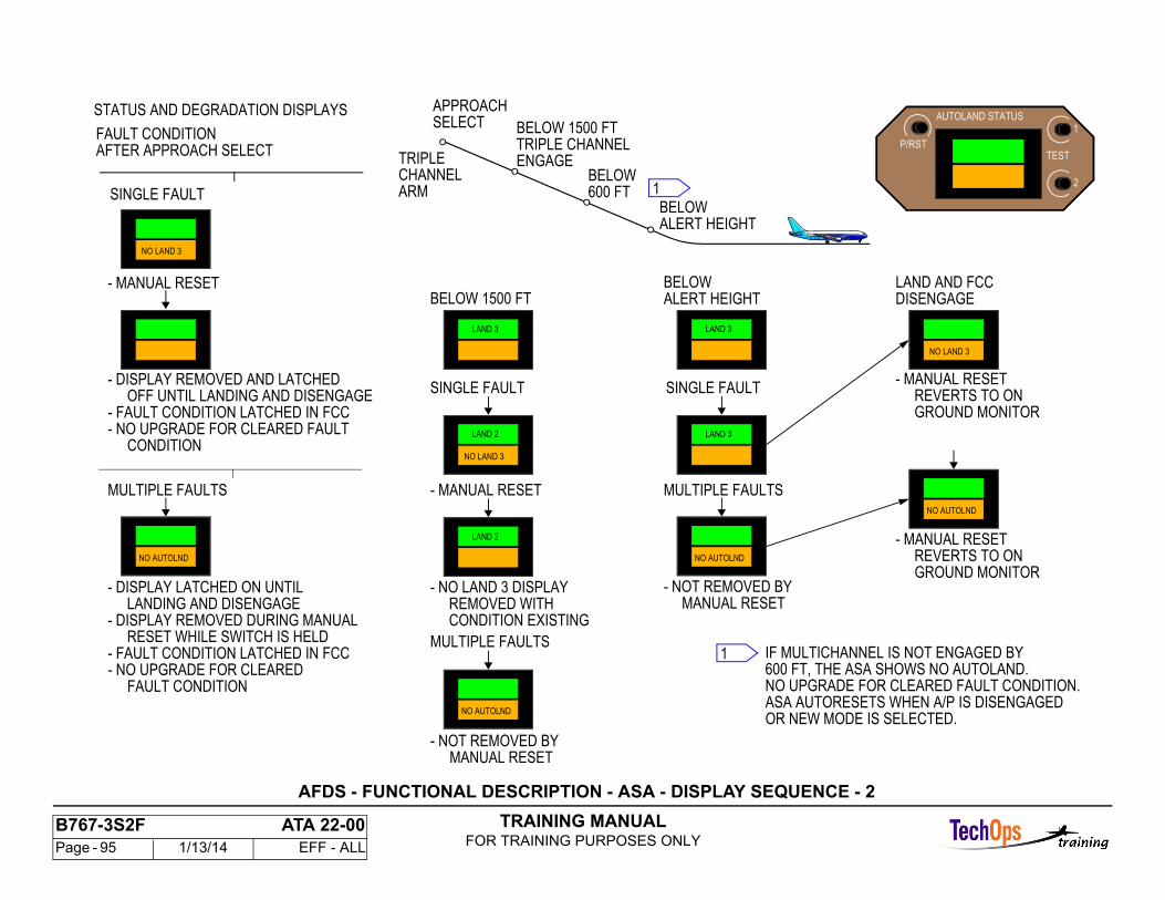
TRAINING MANUALFOR TRAINING PURPOSES ONLY
B767-3S2F ATA 22-00 Page - 95 1/13/14 EFF - ALL
STATUS AND DEGRADATION DISPLAYSBELOW 1500 FT
BELOW 1500 FT
SINGLE FAULT
BELOWALERT HEIGHT
LAND AND FCC
- MANUAL RESET
MULTIPLE FAULTS
- NO LAND 3 DISPLAYREMOVED WITHCONDITION EXISTING
- NOT REMOVED BYMANUAL RESET
SINGLE FAULT
MULTIPLE FAULTS
- NOT REMOVED BYMANUAL RESET
- MANUAL RESET
GROUND MONITOR
BELOWALERT HEIGHT
APPROACHSELECT
TRIPLECHANNEL
TRIPLE CHANNELENGAGE
ARMBELOW
IF MULTICHANNEL IS NOT ENGAGED BY600 FT, THE ASA SHOWS NO AUTOLAND.NO UPGRADE FOR CLEARED FAULT CONDITION.ASA AUTORESETS WHEN A/P IS DISENGAGEDOR NEW MODE IS SELECTED.
FAULT CONDITIONAFTER APPROACH SELECT
SINGLE FAULT
MULTIPLE FAULTS
- MANUAL RESET
- DISPLAY LATCHED ON UNTILLANDING AND DISENGAGE
- DISPLAY REMOVED AND LATCHEDOFF UNTIL LANDING AND DISENGAGE
- DISPLAY REMOVED DURING MANUALRESET WHILE SWITCH IS HELD
- FAULT CONDITION LATCHED IN FCC
- FAULT CONDITION LATCHED IN FCC- NO UPGRADE FOR CLEARED FAULT
CONDITION
- NO UPGRADE FOR CLEAREDFAULT CONDITION
1
REVERTS TO ON
- MANUAL RESET
GROUND MONITORREVERTS TO ON
DISENGAGE
600 FT 12
1
TESTP/RST
AUTOLAND STATUS
NO LAND 3
NO AUTOLND
LAND 3
NO LAND 3
LAND 2
NO AUTOLND
NO LAND 3
LAND 2
LAND 3
LAND 3
NO AUTOLND
NO AUTOLND
AFDS - FUNCTIONAL DESCRIPTION - ASA - DISPLAY SEQUENCE - 2
TRAINING MANUALFOR TRAINING PURPOSES ONLY
B767-3S2F ATA 22-00 Page - 96 1/13/14 EFF - ALL
AFDC - FUNCTIONAL DESCRIPTION - ASA - DISPLAY SEQUENCE - 3
General
This page continues the autoland status annunciatordiaplay sequence.
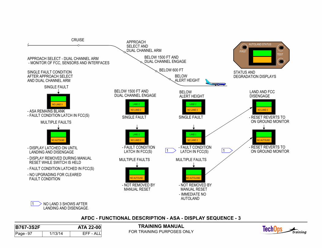
TRAINING MANUALFOR TRAINING PURPOSES ONLY
B767-3S2F ATA 22-00 Page - 97 1/13/14 EFF - ALL
AFTER APPROACH SELECT
- FAULT CONDITION LATCH IN FCC(S)- ASA REMAINS BLANK
APPROACH SELECT - DUAL CHANNEL ARM
- FAULT CONDITION LATCHED IN FCC(S)
SINGLE FAULT CONDITION
FAULT CONDITION- NO UPGRADING FOR CLEARED
- MONITOR OF FCC, SENSORS AND INTERFACES
RESET WHILE SWITCH IS HELD- DISPLAY REMOVED DURING MANUAL
LANDING AND DISENGAGE- DISPLAY LATCHED ON UNTIL
MULTIPLE FAULTS
SINGLE FAULT
- RESET REVERTS TO
DUAL CHANNEL ENGAGE
DUAL CHANNEL ENGAGE
DUAL CHANNEL ARMSELECT AND
BELOW 1500 FT AND
BELOW 1500 FT AND
APPROACH
ALERT HEIGHTBELOW
MANUAL RESET- NOT REMOVED BY
MULTIPLE FAULTS
DISENGAGELAND AND FCC
ALERT HEIGHTBELOW
SINGLE FAULT
CRUISE
STATUS ANDBELOW 600 FT
- FAULT CONDITION LATCH IN FCC(S)
ON GROUND MONITOR
- RESET REVERTS TO ON GROUND MONITOR
NO LAND 3 SHOWS AFTERLANDING AND DISENGAGE.
1
MANUAL RESET- NOT REMOVED BY
MULTIPLE FAULTS
SINGLE FAULT
- FAULT CONDITION LATCH IN FCC(S) 1
1
AND DUAL CHANNEL ARMDEGRADATION DISPLAYS
AUTOLAND- IMMEDIATE NO
2
1
TESTP/RST
AUTOLAND STATUS
NO LAND 3
NO AUTOLND
NO LAND 3
LAND 2
NO LAND 3
LAND 2
NO AUTOLND
NO LAND 3
LAND 2
NO LAND 3
LAND 2
NO AUTOLAND
NO LAND 3
NO AUTOLND
AFDC - FUNCTIONAL DESCRIPTION - ASA - DISPLAY SEQUENCE - 3
TRAINING MANUALFOR TRAINING PURPOSES ONLY
B767-3S2F ATA 22-00 Page - 98 1/13/14 EFF - ALL
AFDS - FUNCTIONAL DESCRIPTION - ASA - DISPLAY SEQUENCE - 4
General
This page continues the autoland status annunciator display sequence.
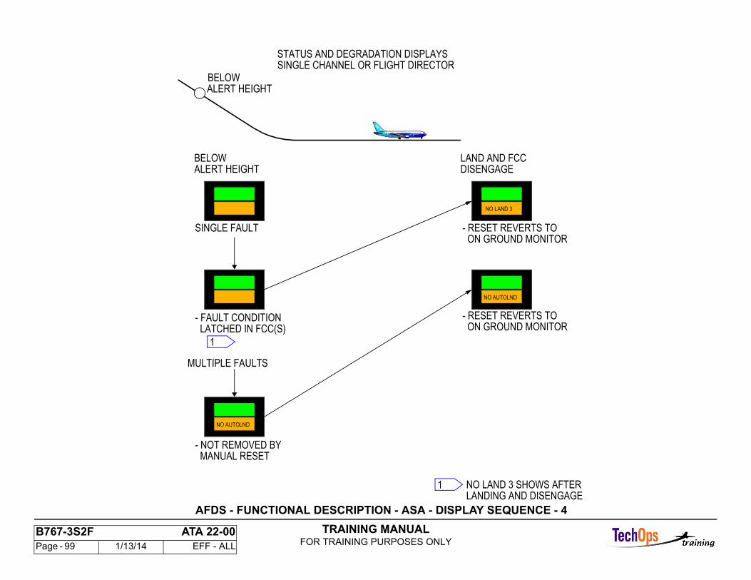
TRAINING MANUALFOR TRAINING PURPOSES ONLY
B767-3S2F ATA 22-00 Page - 99 1/13/14 EFF - ALL
SINGLE CHANNEL OR FLIGHT DIRECTOR
LATCHED IN FCC(S)- FAULT CONDITION
ALERT HEIGHTBELOW
MANUAL RESET- NOT REMOVED BY
MULTIPLE FAULTS
SINGLE FAULT
DISENGAGELAND AND FCC
ALERT HEIGHTBELOW
LANDING AND DISENGAGENO LAND 3 SHOWS AFTER
STATUS AND DEGRADATION DISPLAYS
- RESET REVERTS TO ON GROUND MONITOR
1
1
- RESET REVERTS TO ON GROUND MONITOR
NO AUTOLND
NO LAND 3
NO AUTOLND
AFDS - FUNCTIONAL DESCRIPTION - ASA - DISPLAY SEQUENCE - 4
TRAINING MANUALFOR TRAINING PURPOSES ONLY
B767-3S2F ATA 22-00 Page - 100 1/13/14 EFF - ALL
MODE CONTROL PANEL INTERNALS
General
To accomplish the requirement that a single failure will not cause total loss of the AFDS mode control panel function, the mode control panel contains two separate control channels with a common display. Each channel is powered from a different airplane 28 volt dc source.
The A channel is supplied by the left dc bus and the B channel is supplied by the right dc bus. The A channel receives ARINC 429 data from the left and center flight control computers (FCC) and from the thrust management computer (TMC).
The B channel receives ARINC 429 data from the right and center flight control computers and from the thrust management computer. Each channel independently processes the 429 bus received data. The pilot input front panel data drives its own ARINC 429 bus which transmits that data to the appropriate receiving computers.
Front Panel Switches
Each channel receives data from each switch or encoder on the front panel. Electrical isolation is maintained between each switch contact set and each encoder's A and B channel outputs to ensure system redundancy.The autopilot disengage bar and the autothrottle arm switch provide a positive disengagement function.
Input and Output Discretes
A master test input to each channel allows for external testing of the lights for all dot bars simultaneously.
Front Panel Displays
Each channel can control the common numerical displays since each channel's bi-directional data buffers are connected together. Only a single channel will provide data to the displays; the channel not in command is in the read mode (high impedance) to avoid potential conflicts.
Monitors
Power supply monitoring hardware supplies appropriate reset signals to the CPU when power supplies have fallen below minimum values. A compute-cycle monitor verifies that the CPU is capable of periodic execution to re-start a hardware watchdog timer. If the timer is not restarted every 150 to 200 milliseconds, the critical portions of the I/O system and associated CPU are disabled allowing the alternate CPU to assume control without interference.
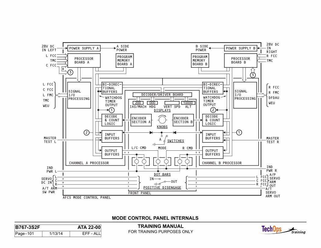
TRAINING MANUALFOR TRAINING PURPOSES ONLY
B767-3S2F ATA 22-00 Page - 101 1/13/14 EFF - ALL
MODE CONTROL PANEL INTERNALS
TRAINING MANUALFOR TRAINING PURPOSES ONLY
B767-3S2F ATA 22-00 Page - 102 1/13/14 EFF - ALL
ENGAGE LOGIC - SIMPLIFIED
General
Engagement of the autopilot servos is a two-step process. Arm status is achieved first if all arm conditions are met and removal conditions are not present. Engage status is achieved second if engage removal conditions or faults do not exist. Details of the logic statements shown here are developed later. The engagement process is comprised of two operations elevator/aileron engagement and rudder engagement.
Elevator/Aileron Engagement
Arm is initiated by command request from the MCP if single channel engaged and by command request and approach mode with another channel engaged. With the arm latch set, the elevator/aileron arm relay is energized which will energize the arm solenoid. The arm latch also enables the engage logic. If conditions are valid for engagement, the engage latch will be set energizing the elevator/aileron engage relay. When the engage latch is set, the arm latch is bypassed and arm removal faults will not disengage the autopilot.
Rudder Engagement
Rudder engagement is initiated by multi-channel arm during approach. This sets the rudder arm latch and, like the elevator/aileron engagement, the arm relay and arm solenoid are energized and the engage logic is enabled. Rudder engage is achieved when two channels are engaged if local channel is one of them. Notice that rudder engagement is removed if local channel disengages or if there is no foreign channel engaged.
ENGAGE INTERLOCKS - OPERATIONElevator and Aileron Arm
The arm function is initiated by pressing the CMD pushbutton. This causes a request to be transmitted via the data bus to the arm logic. When the arm state is achieved, a solid state switch is closed, energizing the elevator/aileron arm relay. This relay supplies 28v dc to energize the elevator and aileron arm solenoids within the autopilot servos. The arm state is also transmitted to the MCP to illuminate the CMD pushbutton.
Elevator and Aileron Engage
The engage function is initiated when the arm state is achieved. The elevator/aileron engage relay operates similarly to the arm relay to energize the engage solenoid in the elevator and lateral autopilot servos.
Rudder Arm
Rudder arm is initiated by multichannel operation which is enabled only in the approach mode. The rudder arm solenoid is energized through the rudder arm relay similar to elevator/aileron arm.
Rudder Engage
Upon achieving rudder arm status, the rudder engage logic is initiated leading to the energizing of the rudder engage solenoid when multichannel engaged.
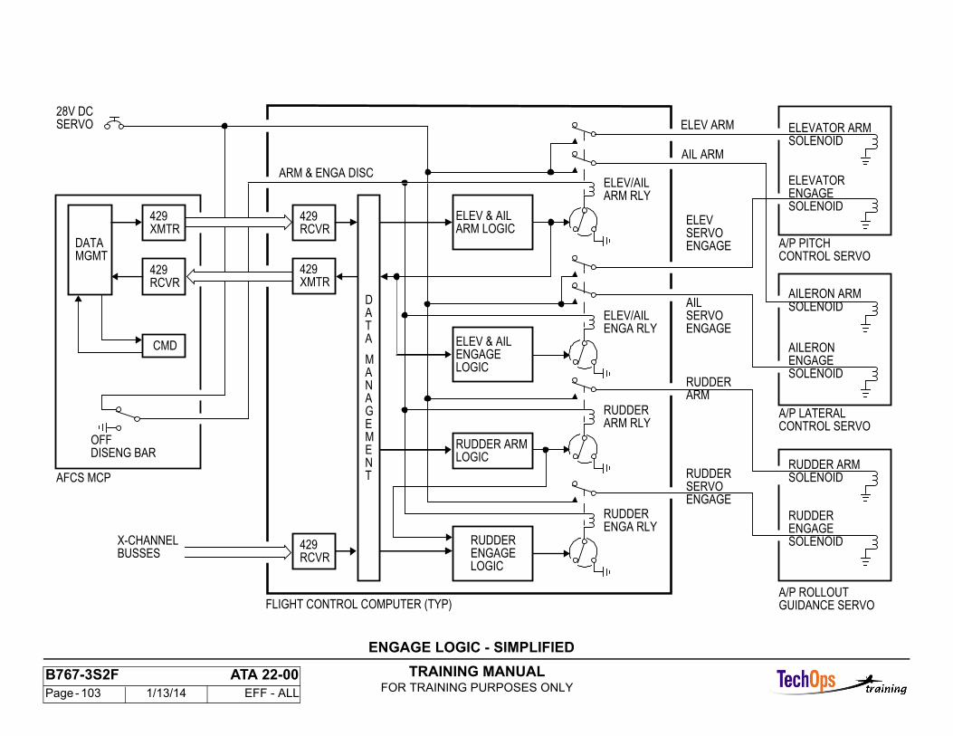
TRAINING MANUALFOR TRAINING PURPOSES ONLY
B767-3S2F ATA 22-00 Page - 103 1/13/14 EFF - ALL
SERVO28V DC
ARM & ENGA DISC
CMD
AFCS MCP
DISENG BAR
X-CHANNELBUSSES
ELEV & AILARM LOGIC
ELEV & AILENGAGELOGIC
RUDDER ARMLOGIC
RUDDERENGAGELOGIC
FLIGHT CONTROL COMPUTER (TYP)
OFF
ELEV/AILARM RLY
ENGA RLYELEV/AIL
RUDDERARM RLY
RUDDERENGA RLY
ELEV
ENGAGE
AIL
RUDDERARM
RUDDERSERVOENGAGE
ELEVATOR ARMSOLENOID
ELEVATORENGAGESOLENOID
CONTROL SERVO
AILERON ARMSOLENOID
AILERONENGAGESOLENOID
CONTROL SERVO
ENGAGE
RUDDER ARMSOLENOID
RUDDERENGAGESOLENOID
ELEV ARM
AIL ARM
A/P PITCH
A/P LATERAL
A/P ROLLOUTGUIDANCE SERVO
429XMTR
429XMTR
429RCVR
429RCVR
429RCVR
DATAMGMT
DATA
MANAGEMENT
SERVO
SERVO
ENGAGE LOGIC - SIMPLIFIED

TRAINING MANUALFOR TRAINING PURPOSES ONLY
B767-3S2F ATA 22-00 Page - 104 1/13/14 EFF - ALL
ENGAGE LOGIC DETAILS - HARDWARE MONITORS
General
The hardware monitor logic receives the arm or engage logic developed previously and if conditions are appropriate, passes this logic to the arm and engage and for rudder arm and engage.
Elevator/Aileron Arm
For elevator/aileron arm, wheel disengage, computer valid and power supplyvalid are monitored.
Elevator/Aileron Engage
For elevator/aileron engagement, the same things are monitored. In addition,camout (local and foreign) is also monitored. Camout is determined within the local channel by the detent comparator. Detent logic remains high as long as the servo LVDT and surface LVDT agree within the limits shown. MY DETENT logic low will cause a camout disengage only if there is another channel servo engaged.
Relative left or right channel camout (detent low) will cause disengagement ifthe foreign channel disengages with a detent trip and it is the only other channelengaged. In other words, for dual configuration if one channel has a detent trip,both channels disengage. Rudder Arm For rudder engagement, ELEV/AILPREARM and power supply valid is necessary in addition to ROLLOUT ARM.
Rudder Engage
For rudder engagement logic, ELEV/AIL PRE-ENGA and FOREIGN SERVOENGA are necessary in addition to ROLLOUT ENGA and power supply valid.
AFDS Annunciations
If the autopilot is single channel engaged, a camout will cause an autopilot caution annunciation.
If the autopilot is dual channel engaged, a camout will cause an autopilot disconnect annunciation with a no autoland annunciation on the ASA.If the autopilot is triple channel engaged, a single channel camout will cause; ifabove the alert height, a LAND 2/NO LAND 3 annunciation on the ASA; if belowthe alert height, the ASA will annunciate LAND 3 and there will be no changesuntil touchdown and disconnect. The ASA will then annunciate NO LAND 3.If the autopilot is triple channel engaged a dual or triple channel camout willcause an autopilot disconnect annunciation and NO AUTOLAND on the ASA.
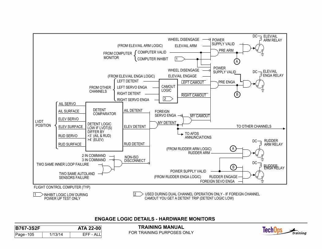
TRAINING MANUALFOR TRAINING PURPOSES ONLY
B767-3S2F ATA 22-00 Page - 105 1/13/14 EFF - ALL
COMPUTER INHIBIT
TWO SAME AUTOLAND
TWO SAME INNER LOOP FAILUREB
B
ANNUNCIATIONSTO AFDS
ELEV/AIL ENGAGE
>4` (ELEV)>3` (AIL & RUD)DIFFER BY
ENGA RELAY
ARM RELAY
ENGA RELAY
ARM RELAY
WHEEL DISENGAGE
POWER SUPPLY VALID
POWER
POWER
TO OTHER CHANNELS
FLIGHT CONTROL COMPUTER (TYP)
CAMOUT YOU GET A DETENT TRIP (DETENT LOGIC LOW)USED DURING DUAL CHANNEL OPERATION ONLY - IF FOREIGN CHANNEL
POWER UP TEST ONLYINHIBIT LOGIC LOW DURING
FOREIGN SEVO ENGA
RUDDER
RUDDER ENGAGE
RUDDER
RUDDER ARM
FOREIGNMY CAMOUT
MY DETENT
3 IN COMMANDNON-ISO
AIL DETENT
CHANNELS FROM OTHER
RUD SURFACE
RUD SERVO
ELEV SURFACE
ELEV SERVO
AIL SURFACE
AIL SERVO
LVDT
LOW IF LVDT(S) DETENT LOGIC
COMPARATORDETENT
LOGIC CAMOUT
ELEV/AIL
PRE ENGA
ELEV/AIL
PRE ARM
(FROM ELEV/AIL ENGA LOGIC)
(FROM RUDDER ENGA LOGIC)
(FROM RUDDER ARM LOGIC)
COMPUTER VALID
ELEV/AIL ARM
WHEEL DISENGAGE
2 IN COMMAND
DISCONNECT
RUD DETENT
ELEV DETENT
RIGHT CAMOUT
LEFT CAMOUT
RIGHT SERVO ENGA
RIGHT DETENT
LEFT DETENT
POSITION
SERVO ENGA
SENSORS FAILURE
SUPPLY VALID
SUPPLY VALID
LEFT SERVO ENGA
2
1
1 2
A
A
DC
DC
DC
DC
(FROM ELEV/AIL ARM LOGIC)
MONITOR FROM COMPUTER
ENGAGE LOGIC DETAILS - HARDWARE MONITORS
TRAINING MANUALFOR TRAINING PURPOSES ONLY
B767-3S2F ATA 22-00 Page - 106 1/13/14 EFF - ALL
INTERFACE - FCC CROSS-CHANNEL DATA
General
Digital data is transmitted cross-channel between FCCs for monitor, signal selection, and synchronization. The analog discrete logic for servo engage and detent trip also go on the cross-channel. They go to dedicated hardware to provide a redundant path for failed FCC disengagement.
Digital Interfaces
The digital data buses are ARINC 429 high speed buses. Cross-channel bus parameter labels generally are not identical to the respective source label. This allows a simplified, combined cross-channel receive function.
Analog Discrete Interfaces
These discretes are either ground or 28v dc.
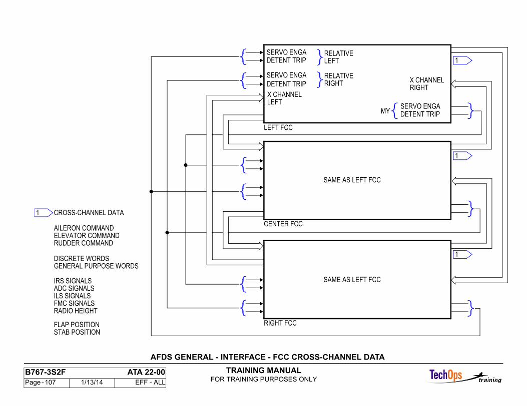
TRAINING MANUALFOR TRAINING PURPOSES ONLY
B767-3S2F ATA 22-00 Page - 107 1/13/14 EFF - ALL
CENTER FCC
IRS SIGNALSADC SIGNALSILS SIGNALS
FLAP POSITIONSTAB POSITION
FMC SIGNALSRADIO HEIGHT
ELEVATOR COMMANDAILERON COMMAND
CROSS-CHANNEL DATA
RUDDER COMMAND
DISCRETE WORDSGENERAL PURPOSE WORDS
1
1
1
1
RIGHTX CHANNEL
MY DETENT TRIPSERVO ENGA
LEFTRELATIVE
DETENT TRIPSERVO ENGA
RIGHTRELATIVE
DETENT TRIP
SERVO ENGA
X CHANNEL
LEFT FCC
LEFT
RIGHT FCC
SAME AS LEFT FCC
SAME AS LEFT FCC
AFDS GENERAL - INTERFACE - FCC CROSS-CHANNEL DATA
TRAINING MANUALFOR TRAINING PURPOSES ONLY
B767-3S2F ATA 22-00 Page - 108 1/13/14 EFF - ALL
AFDS POWER DISTRIBUTION
General Distribution
The power distribution for the AFDS is organized around the three channel configuration of the flight control computers, the dual configuration of the mode control panel, and the dual requirements of the annunciation and caution and warning designs.
Each FCC gets power from a separate ac and dc bus. The dc standby bus provides the second source of annunciation and warning power to each FCC and to each autoland status annunciator.
AFDS AC Power The 115v ac primary power to each FCC is changed to 26v ac and used for sensor excitation and to make several dc levels for the electronic circuits. An automatic reset circuit breaker protects the 26v ac output. Lighting power (5v ac) goes to the AFCS mode control panel and each autoland status annunciator for background lighting.
FCC DC Power Two external dc sources go to each FCC. The AFCS warning power dc and that developed from the 115v ac power provide the dual sources necessary forannunciation and warning.
AFCS MCP DC Power
The AFCS MCP uses two sources for logic power and two sources for master dim and master test of the indicator lights. Each FCC SERVO dc goes through the AFCS MCP to allow positive disengagement of the servos from theAFCS MCP.
The left and right logic power dc inputs supply the left and right side AFCS MCP electronics respectively. The left and right indicator power inputs provide thepower to the left half and right half of each dot bar display.
Autoland Status Annunciators (ASA) DC Power
Each ASA uses two sources of dc power to provide the necessary power redundancy.
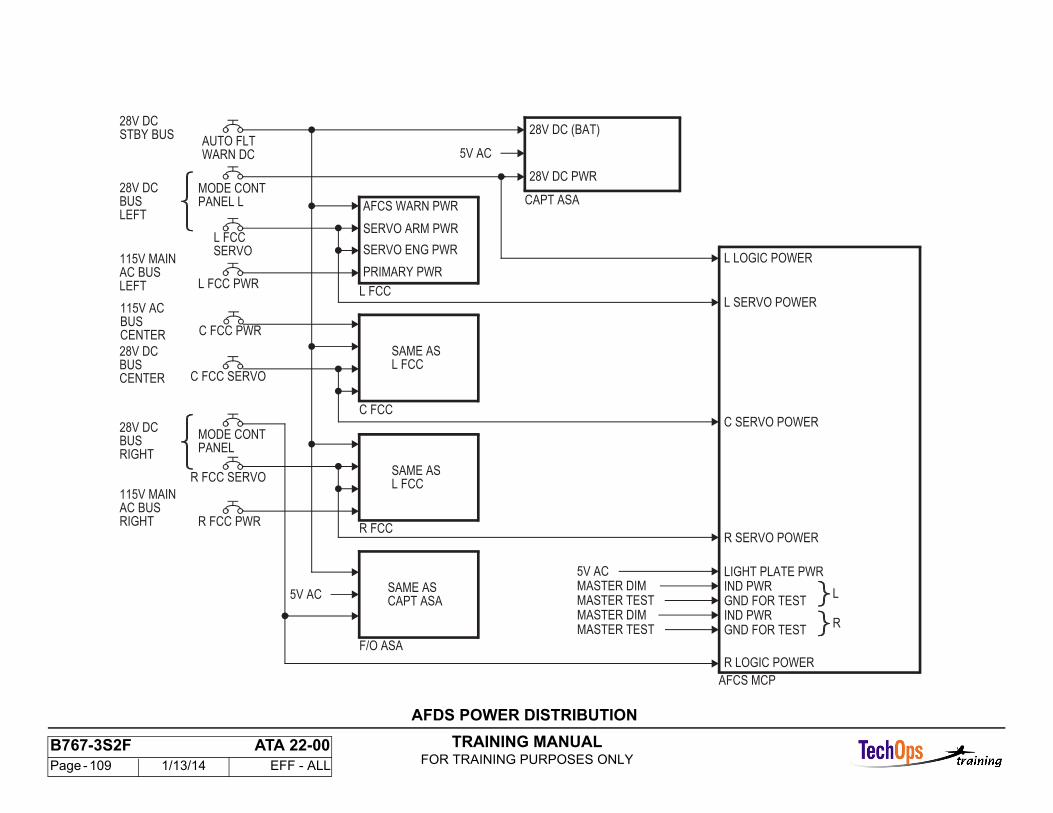
TRAINING MANUALFOR TRAINING PURPOSES ONLY
B767-3S2F ATA 22-00 Page - 109 1/13/14 EFF - ALL
SAME ASL FCCBUS
CENTER
L
28V DC PWR
CAPT ASA
5V AC
5V ACMASTER DIMMASTER TEST
AFCS WARN PWR
SERVO ARM PWR
SERVO ENG PWR
PRIMARY PWR
L FCC
28V DC
28V DCBUSLEFT
L LOGIC POWER
C FCC
CENTER
L SERVO POWER
C SERVO POWER28V DCBUSRIGHT
R FCCR SERVO POWER
LIGHT PLATE PWRIND PWRGND FOR TESTIND PWRGND FOR TEST
R
R LOGIC POWER
AFCS MCP
F/O ASA
5V AC
MASTER DIMMASTER TEST
STBY BUSAUTO FLT
115V MAINAC BUS
115V MAINAC BUSRIGHT
R FCC SERVO
BUS
L FCC PWR
C FCC SERVO
C FCC PWR
R FCC PWR
MODE CONTPANEL
L FCC
MODE CONTPANEL L
WARN DC
28V DC (BAT)
LEFT
SERVO
28V DC
115V AC
SAME ASCAPT ASA
SAME ASL FCC
AFDS POWER DISTRIBUTION
TRAINING MANUALFOR TRAINING PURPOSES ONLY
B767-3S2F ATA 22-00 Page - 110 1/13/14 EFF - ALL
AFDS FCC POWER DISTRIBUTION
FCC AC Power
Each autopilot servo receives 26vac for LVDT excitation from its FCC.
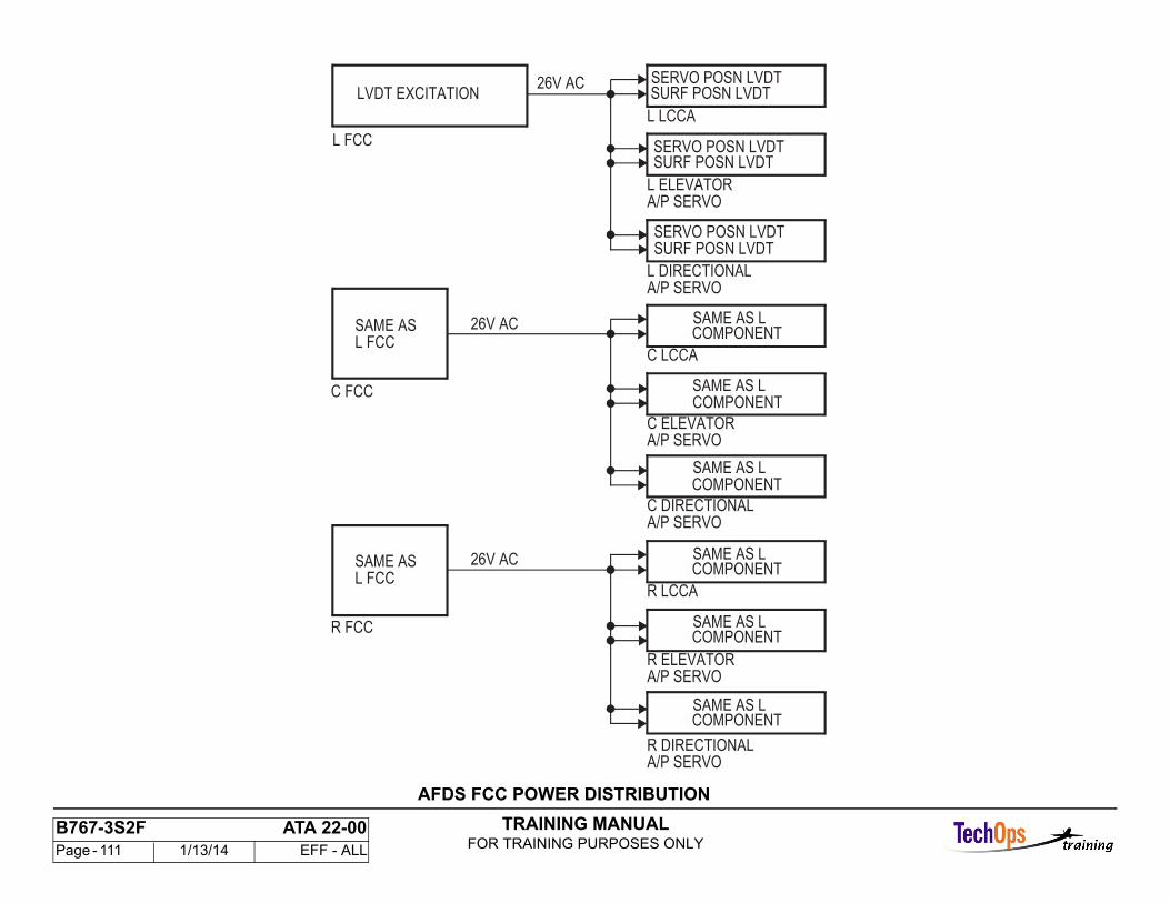
TRAINING MANUALFOR TRAINING PURPOSES ONLY
B767-3S2F ATA 22-00 Page - 111 1/13/14 EFF - ALL
LVDT EXCITATION
L FCC
26V AC
C FCC
26V AC
SAME ASL FCC
26V ACSURF POSN LVDT
SERVO POSN LVDTSURF POSN LVDT
SERVO POSN LVDTSURF POSN LVDT
L LCCA
C LCCA
R LCCA
A/P SERVO
A/P SERVO
A/P SERVO
A/P SERVO
A/P SERVO
A/P SERVO
R ELEVATOR
R DIRECTIONAL
C DIRECTIONAL
C ELEVATOR
L DIRECTIONAL
L ELEVATOR
SERVO POSN LVDT
SAME AS LCOMPONENT
SAME AS LCOMPONENT
SAME AS LCOMPONENT
SAME AS LCOMPONENT
SAME AS LCOMPONENT
SAME AS LCOMPONENT
R FCC
SAME ASL FCC
AFDS FCC POWER DISTRIBUTION
TRAINING MANUALFOR TRAINING PURPOSES ONLY
B767-3S2F ATA 22-00 Page - 112 1/13/14 EFF - ALL
AUTOLAND POWER SWITCHING - FUNCTIONAL DESCRIPTION
General
It is necessary for the airplane to have Category III B capability. The categories are established by the regulatory agencies based on these factors:
- Airplane certification- Airport facilities- Flight crew proficiency- Airline maintenance.
The runway visual range (RVR) and decision height (DH) requirements established for category III B are typically 150 - 700 ft RVR and 0 ft DH. These numbers are based on a fail-operational capability. This is the level of redundancy necessary such that if there is a single failure that occurrs below the alert height, the landing may be continued with the remainder of theautomatic system. For a fail-operational capabilty, triple redundancy of these is necessary:
- Power sources- Engaged FCCs- Sensors- Servos.
After the FCCs send an autoland bus isolate command to the isolation request relay (K122), they monitor a bus isolation signal.
Normal Configuration
During non-autoland conditions, the left and right generator circuit breakers (GCB) are closed, the bus tie breakers (BTB) are open, and the K107 center bus transfer relay is de-energized. The center bus ac and dc is supplied from the left main ac and dc buses respectively.
Autoland Configuration
When the three autopilots are armed for approach and there are no faults, the center buses transfer from the left system to the standby system. This provides three independent power sources for the three autopilots. At the same time, the
bus tie breakers (BTBs) go into the isolation mode. In the isolation mode, both BTBs can not be closed to supply power to the two main busesfrom one source.
Operation
The standby electrical system is an independent power source to supply the center autopilot during autoland operation. During autoland operation, the battery charger (which operates in the T-R mode as a constant voltage source) is the third power source. The battery provides instantaneous backup if the battery charger fails.
An autoland bus isolate request starts the center bus transfer. When the K122 ISLN REQUEST relay is energized, a 28v dc signal (Autoland CMD) goes to the bus power control unit (BPCU). The BPCU sends an autoland lockout command to the left and right generator control units to inhibit BTB close command logic. At least one BTB must be open and one GCB closed to energize the autoland relays (K526 and K527). For backup protection, the circuit to the BTB close coil is open to interrupt any BTB close command when the autoland relay is energized.
When either K526 or K527 is energized, if the static inverter is operational, relay K2127 energizes. This lets center isolation relay, K123, energized. If thebattery switch is ON, K2128 and K107 (center bus transfer relay) energize switching the center buses. Additional contacts of relay K2128 bypass K2127 after isolation occurs. After center bus transfer is complete, the bus isolated ground input (from K108) is removed when K107 is energized.
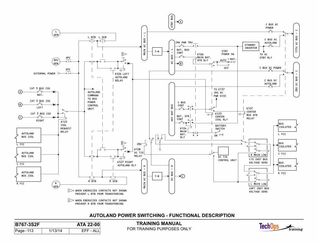
TRAINING MANUALFOR TRAINING PURPOSES ONLY
B767-3S2F ATA 22-00 Page - 113 1/13/14 EFF - ALL
AUTOLAND POWER SWITCHING - FUNCTIONAL DESCRIPTION
AUTOLANDBUS ISOL
RGEN
R FCC
CAT 3 BUS ISO
ISOLREQUESTRELAY
APC
EPC
AUTOLANDBUS ISOL
C FCC
AUTOLANDBUS ISOL
L FCC
C
CAT 3 BUS ISO
B
CAT 3 BUS ISO
A
APUGEN
L BTB L GCBGEN
2
R GCBR BTB
MAIN AC BUS - R
T-R C
MAIN AC BUS - L
T-R
STBY BUS
1
AUTOLANDCOMMANDTO BUSPOWERCONTROLUNIT
K106
XFR RLY B
STBY
AUTO
OFF
STANDBY INVERTER
K123
ISOL RLY
CONT
CONT
K104MAIN
RLY
SWITCH
ON
INV PWR TRU
1 WHEN ENERGIZED CONTACTS NOT SHOWNPREVENT L BTB FROM TRANSFERRING
WHEN ENERGIZED CONTACTS NOT SHOWNPREVENT R BTB FROM TRANSFERRING
2
K122
AUTOLAND RLYK527 RIGHT
AUTOLANDRELAY
L
C BUS
AC BUS AC
C BUS AC
TO ACSTBY RLY
POWER SW
28V DC BUS - C
C BUS DC
BUSISOLATED
L FCC
BUSISOLATED
BUSISOLATED
C FCC
R FCC
K107
BUS XFR
EXTERNAL POWER
115V AC BUS - C
DC BUS - R
HOT BAT BUS
DC BUS - L
K526 LEFT
RIGHT
LEFT
BAT.
CONTBAT. BUS
MAIN BAT. BAT.
BAT. XFR
C BUS DC POWER
BAT.
AUTOLAND
POWER
AUTOLAND
28V
K108
BATTERY
CENTER
R MAIN LOW
F/O INST BUSVOLTAGE SENS
VOLTAGE SENS
CENTERRELAY
DC TIECONTROL UNIT
IRS DCPWR DISC
TO K137
L MAIN LOW
CAPT INST BUS
DC TIERELAY
TRAINING MANUALFOR TRAINING PURPOSES ONLY
B767-3S2F ATA 22-00 Page - 114 1/13/14 EFF - ALL
AUTOLAND POWER SWITCHING - FUNCTIONAL DESCRIPTION CONT.
Bus Isolation Signal
The bus isolation sigmal shows that the buses are isolated. All three channels have an independent source of power. The bus isolation condition is removed in one of these three ways:
- Radio altitude is above 200 feet and a fault has been detected which results in a NO LAND 3 condition- After start of an auto go-around when the airplane is above 100 feet radio altitude and a positive rate of climb has been established- All autopilots are disconnected.
Generator Loss Above 200 Feet
Between arming of the three autopilots and 200 feet, the loss of a generator is sensed by either the captain or first officer instrument bus voltage sensing unit.Either unit energizes to keep the flight instrument transfer bus powered, energize the dc tie relay (K108), and signals the FCCs that the buses are not isolated (re-applies ground to bus isolate signal). The FCCs remove the autoland bus isolate ground. This hanges the center buses back to left main ac and dc buses. Also the bus tie breakers close to supply power to both main ac buses.
Generator Loss Below 200 Feet
If a generator is lost below 200 feet radio altitude, the loss of generator is sensed by either instrument bus voltage sensing unit. Either unit energizes aspreviously discussed. Below 200 feet, the FCCs do not remove the autoland bus isolate request (ground) and K122 remains energized. The three autopilots remain isolated. Because of the generator loss, one of the autopilots is also lost, and the automatic approach continues with the remaining two autopilots.
APU Generator Backup Power
If the APU generator is on during a multichannel approach, it supplies power to the main ac bus of the failed generator, regardless of altitude.
A generator failure causes the generator circuit breaker (GCB) to trip open. This causes the corresponding autoland relay to de-energize and the BPCU to directly sense the GCB position. An open GCB causes the BPCU to remove the autoland lockout command from the corresponding GCU and allowsautomatic BTB closure. Transfer to the APU generator may result in a powerinterruption from less than 0.05 seconds to 10 seconds, depending on the type of failure.
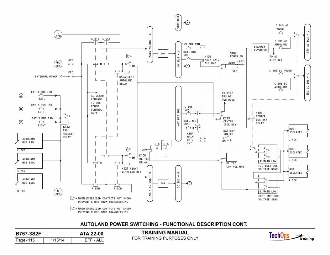
TRAINING MANUALFOR TRAINING PURPOSES ONLY
B767-3S2F ATA 22-00 Page - 115 1/13/14 EFF - ALL
AUTOLAND POWER SWITCHING - FUNCTIONAL DESCRIPTION CONT.
AUTOLANDBUS ISOL
RGEN
R FCC
CAT 3 BUS ISO
ISOLREQUESTRELAY
APC
EPC
AUTOLANDBUS ISOL
C FCC
AUTOLANDBUS ISOL
L FCC
C
CAT 3 BUS ISO
B
CAT 3 BUS ISO
A
APUGEN
L BTB L GCBGEN
2
R GCBR BTB
MAIN AC BUS - R
T-R C
MAIN AC BUS - L
T-R
STBY BUS
1
AUTOLANDCOMMANDTO BUSPOWERCONTROLUNIT
K106
XFR RLY B
STBY
AUTO
OFF
STANDBY INVERTER
K123
ISOL RLY
CONT
CONT
K104MAIN
RLY
SWITCH
ON
INV PWR TRU
1 WHEN ENERGIZED CONTACTS NOT SHOWNPREVENT L BTB FROM TRANSFERRING
WHEN ENERGIZED CONTACTS NOT SHOWNPREVENT R BTB FROM TRANSFERRING
2
K122
AUTOLAND RLYK527 RIGHT
AUTOLANDRELAY
L
C BUS
AC BUS AC
C BUS AC
TO ACSTBY RLY
POWER SW
28V DC BUS - C
C BUS DC
BUSISOLATED
L FCC
BUSISOLATED
BUSISOLATED
C FCC
R FCC
K107
BUS XFR
EXTERNAL POWER
115V AC BUS - C
DC BUS - R
HOT BAT BUS
DC BUS - L
K526 LEFT
RIGHT
LEFT
BAT.
CONTBAT. BUS
MAIN BAT. BAT.
BAT. XFR
C BUS DC POWER
BAT.
AUTOLAND
POWER
AUTOLAND
28V
K108
BATTERY
CENTER
R MAIN LOW
F/O INST BUSVOLTAGE SENS
VOLTAGE SENS
CENTERRELAY
DC TIECONTROL UNIT
IRS DCPWR DISC
TO K137
L MAIN LOW
CAPT INST BUS
DC TIERELAY
TRAINING MANUALFOR TRAINING PURPOSES ONLY
B767-3S2F ATA 22-00 Page - 116 1/13/14 EFF - ALL
AFDS GENERAL - POWER ISOLATION LOGIC
General
The purpose of the power isolation logic is to cause the power sources to separate during a triple-channel approach.
The power isolation logic is set when these conditions are true:
- Triple channel arm - all three channels either engaged or armed- None of the three channels make NO LAND 3 logic - Approach mode armed- Airplane above alert height (>200 ft RA). Any of these conditons cause the power isolation logic to reset:- Total autopilot disconnect- Any channel makes NO LAND 3 logic above alert height- Go-around started.
Note: NO LAND 3 status will cause power isolation logic to be reset but the reset of fail-operative capability will not restart power isolation logic unless the approach mode or triple arm is disengaged and reengaged. Through the power isolation circuits, NO LAND 3 logic will be made if isolation does not occur within 4 seconds of the request by the FCC and isolation will be reset and not requested again.
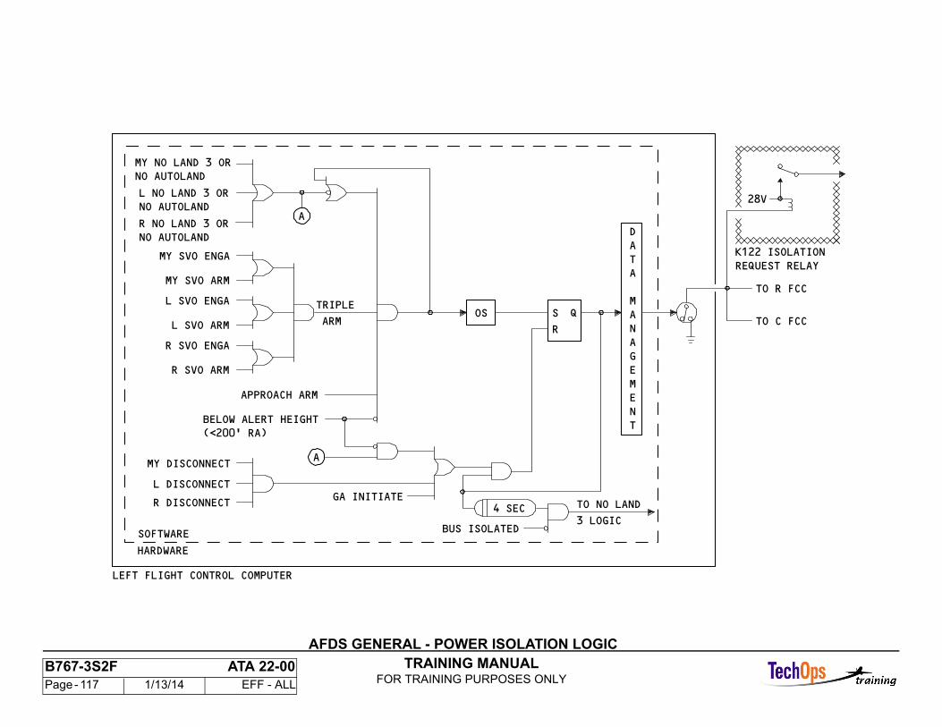
TRAINING MANUALFOR TRAINING PURPOSES ONLY
B767-3S2F ATA 22-00 Page - 117 1/13/14 EFF - ALL
AFDS GENERAL - POWER ISOLATION LOGIC
(<200' RA)BELOW ALERT HEIGHT
NO AUTOLANDR NO LAND 3 OR
NO AUTOLANDL NO LAND 3 OR
NO AUTOLANDMY NO LAND 3 OR
QOS
GA INITIATE
A
TO C FCC
TO R FCC
REQUEST RELAYK122 ISOLATION
28V
TNEMEGANAM
ATAD
R
S
HARDWARE
SOFTWARE3 LOGIC
TO NO LAND
BUS ISOLATED
4 SEC
LEFT FLIGHT CONTROL COMPUTER
A
R DISCONNECT
L DISCONNECT
MY DISCONNECT
R SVO ARM
R SVO ENGA
MY SVO ARM
MY SVO ENGA
L SVO ARM
L SVO ENGA
ARM
TRIPLE
APPROACH ARM
TRAINING MANUALFOR TRAINING PURPOSES ONLY
B767-3S2F ATA 22-00 Page - 118 1/13/14 EFF - ALL
AUTOLAND SEQUENCE
APP
The following is actions of the aircraft’s Autopilot during different phases ofAutoland flight.
• Approach selected on the MCP busses split autopilots not engaged Arm.Center bus powered from the hot battery bus.• GA armed on EICAS as a thrust mode. G/S captured, Flaps not up or G/Abutton selected.• 1500 Ft ASA displays true land status. Remaining Autopilots engage. Flareand Rollout Arm.• 500 Ft De-crab• 300 Ft Stab trim bias• 200 Ft Rising runway. Alert height no one single failure of a system cancause an ASA status change.• 45 Ft Flare• 25 Ft Throttle retard occurs and Idle is displayed on the FMA throttlesector.
GA
Aircraft climbs 2000 feet per min. Wings level following LOC till a different pitch/roll mode is engaged other than GA above 400 Feet.
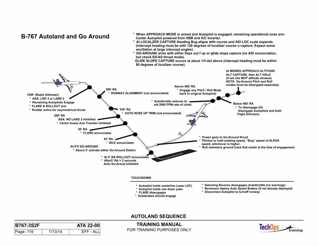
TRAINING MANUALFOR TRAINING PURPOSES ONLY
B767-3S2F ATA 22-00 Page - 119 1/13/14 EFF - ALL
B-767 Autoland and Go Around* When APPROACH MODE is armed and Autopilot is engaged, remaining operational ones arm. Center Autopilot powered from HBB and A/C Inverter.* At LOCALZER CAPTURE Heading Bug aligns with course and ADI LOC scale expands. (intercept heading must be with 120 degrees of localizer course o capture. Expect some oscillation at large intercept angles).* GO-AROUND arms with either flaps out f up or glide slope capture (no ADI annunciation, but check EICAS thrust mode). GLIDE SLOPE CAPTURE occurs at about 1/4 dot above (intercept heading must be within 80 degrees of localizer course).
1500’ (Radio Altimeter)
* ASA: LND 3 or LAND 2
* Remaining Autopilots Engage
* FLARE & ROLLOUT arm
* Rudder active for asymmetrical thrust
200’ RA
ASA: NO LAND 3 inhibited
* Center buses Auo Transfer inhibited
45’ RA
* FLARE annunciates
25’ RA
* IDLE annunciates
AUTO GO-AROUND
* Above 5’ activate either Go-Around Switch
* At 5’ RA ROLLOUT annunciates * After5’ RA + 2 seconds Auto Go-Aroud inhibited
500’ RA
* RUNWAY ALIGNMENT (not annunciated)
330’ RA
* AUTO NOSE UP TRIM (not annunciated)
* Power goes to Go-Around thrust * Pitches to hold existing speed, “Bug” speed of ALPHA speed, whichever is higher. * Roll maintains ground track that exists at the time of engagement.
Below 400’ RA
* To disengage GA disengage Autopilots and both Flight Directors.
Above 400’ RA
* Engage any Pitch / Roll Mode back to original Autopilot)
* Autothrottle reduces to old 2000 FPM rate of climb.
At MISSED APPROACH ALTITUDE:
ALT CAPTURE, then ALT HOLD(if set into MCP altitude window)NOTE: Go-Around Pitch and Rollmodes must be disengaed separately.
TOUCHDOWN
* Autopilot holds centerline (uses LOC) * Autopilot holds nse down yoke * FLARE disengages * Autobrakes should engage
* Selecting Reverse disengages Autothrottle (no warnings) * Reversers deploy Auto Speed Brakes (if not already deployed) * Disconnect Autopilot to turnoff runway
AUTOLAND SEQUENCE

TRAINING MANUALFOR TRAINING PURPOSES ONLY
B767-3S2F ATA 22-00 Page - 120 1/13/14 EFF - ALL
THRUST MANAGEMENT SYSTEM - INTRODUCTION
General
The thrust management system controls engine thrust with mode requests from these:
- Thrust mode select panel (TMSP)- AFCS mode control panel (MCP)- Flight management computing system (FMCS).
The thrust management computer (TMC) uses these mode requests to calculate the autothrottle and thrust limit data.
The TMC also does continuous fault data management and on-ground maintenance tests.
Description
The TMSP supplies thrust limit mode inputs to the TMC for thrust limit calculations.
The MCP supplies autothrottle mode inputs to the TMC for throttle position data.
The FMC supplies data to the TMC to control the throttles and thrust limits.
Sensor Inputs
The TMC uses airplane, navigation, and engine sensors to calculate autothrottle and thrust limit data.
Display Outputs
The TMC shows the autothrottle engage status and modes on the EADIs. It also shows the thrust limit modes and values on EICAS.
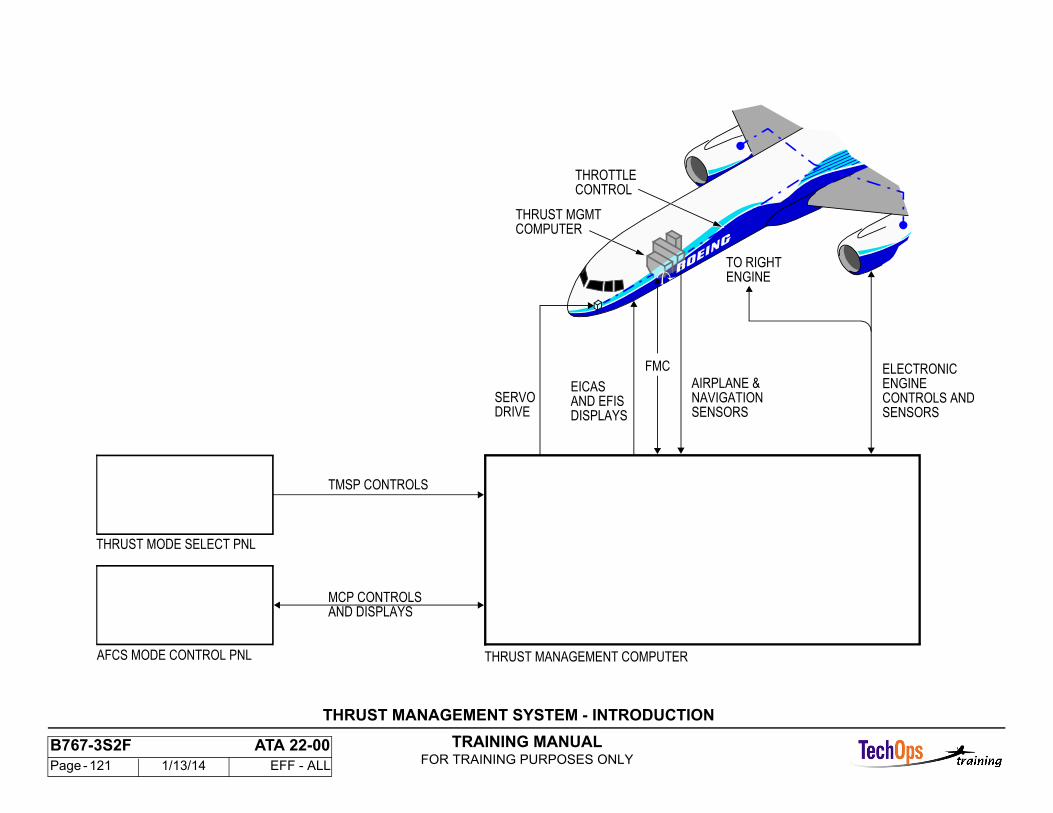
TRAINING MANUALFOR TRAINING PURPOSES ONLY
B767-3S2F ATA 22-00 Page - 121 1/13/14 EFF - ALL
AIRPLANE &
DRIVESERVO
DISPLAYS
EICASAND EFIS
TMSP CONTROLS
MCP CONTROLS
THRUST MODE SELECT PNL
AFCS MODE CONTROL PNL
FMC
ENGINETO RIGHT
THRUST MANAGEMENT COMPUTER
COMPUTERTHRUST MGMT
NAVIGATION
ELECTRONICENGINECONTROLS ANDSENSORS
CONTROLTHROTTLE
SENSORS
AND DISPLAYS
THRUST MANAGEMENT SYSTEM - INTRODUCTION
TRAINING MANUALFOR TRAINING PURPOSES ONLY
B767-3S2F ATA 22-00 Page - 122 1/13/14 EFF - ALL
TMS - COMPONENT LOCATION
General
TMS components are in these locations:
- Flight compartment- Main equipment center.
Flight Compartment Components
The autothrottle ARM and MODE switches are located on the AFCS mode control panel (P-55).
The A/T disconnect light is on the P1 panel. The light is amber.
The autothrottle disengage switches are on the outside of each throttle lever.
The go-around switches are on the lower aft edge of each throttle lever.
The servomotor is on the left side of the autothrottle drive assembly.
The microswitch pack assembly is on the bottom of the autothrottle assembly.
A leading edge slat switch is located behind an access panel to the right of the first officr stabilizer trim indicator.
Main Equipment Center Components
The thrust management computer is on the E1-3 shelf.
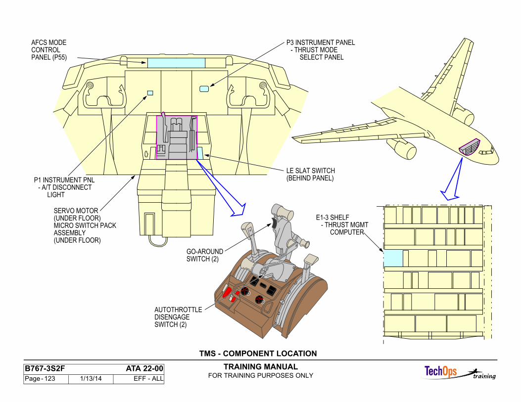
TRAINING MANUALFOR TRAINING PURPOSES ONLY
B767-3S2F ATA 22-00 Page - 123 1/13/14 EFF - ALL
SERVO MOTOR(UNDER FLOOR)MICRO SWITCH PACK
(UNDER FLOOR)ASSEMBLY
- THRUST MGMTCOMPUTER
E1-3 SHELF
- THRUST MODESELECT PANEL
- A/T DISCONNECTLIGHT
P3 INSTRUMENT PANEL
P1 INSTRUMENT PNL
AFCS MODECONTROLPANEL (P55)
LE SLAT SWITCH(BEHIND PANEL)
AUTOTHROTTLEDISENGAGESWITCH (2)
GO-AROUNDSWITCH (2)
TMS - COMPONENT LOCATION
TRAINING MANUALFOR TRAINING PURPOSES ONLY
B767-3S2F ATA 22-00 Page - 124 1/13/14 EFF - ALL
TMS - THROTTLE COMPONENT LOCATION
Autothrottle Servo Motor
The autothrottle servo motor is at WL 200 under thethrottle control stand. It moves the throttle andcables through the clutch pack assembly.
A/T Disengage Switch
One autothrottle disengage switch is on each throttlelever.
Go-Around Switch
Go-around switch input to the TMC is from the sameswitches used by the left flight control computer.Switch Pack AssemblyThe switch pack assembly contains two sets of switches.One set is operated by the left thrust lever. The otheris operated by the right. Thrust reverse switches putthe thrust limit in REV mode and disengage theautothrottle.
Brake Pack Assembly
The servomotor moves the throttle levers through thebrake pack assembly.
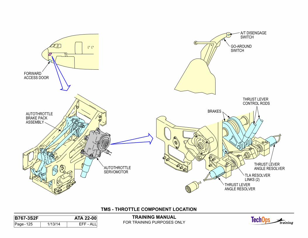
TRAINING MANUALFOR TRAINING PURPOSES ONLY
B767-3S2F ATA 22-00 Page - 125 1/13/14 EFF - ALL
SWITCHA/T DISENGAGE
SWITCHGO-AROUND
ACCESS DOORFORWARD
BRAKE PACK
SERVOMOTORAUTOTHROTTLE
ASSEMBLY
AUTOTHROTTLEBRAKES
ANGLE RESOLVERTHRUST LEVER
LINKS (2)TLA RESOLVER
ANGLE RESOLVERTHRUST LEVER
CONTROL RODSTHRUST LEVER
TMS - THROTTLE COMPONENT LOCATION
TRAINING MANUALFOR TRAINING PURPOSES ONLY
B767-3S2F ATA 22-00 Page - 126 1/13/14 EFF - ALL
TMS - THRUST MODE SELECT PANEL
General Description
The thrust mode select panel weighs 1.5 lb (0.7 kg) and measures 2.26 x 3.27 x 6.9 inches. Power comes from the TMC. There is no internal computer. The panel uses an internal clock to make the ARINC 429 words.
Thrust Limit Mode Selection
You use the TMSP push-button for the necessary manual thrust limit mode. A push-button for the currently selected mode has no effect.
The TO/GA push-button selects:
- Takeoff (TO) thrust limit mode if you push the TO/GA push-button when the airplane is on the ground- Go-around (GA) thrust limit mode if you push the TO/GA push-button when the airplane is in the air.
Thrust Derate Selection
The thrust management system decreases the thrust limit with a fixed derate schedule or an assumed temperature. You select fixed derate schedules with the TMSP derate push-button 1 or 2.
You select an assumed temperature with the temperature selector (TEMP SEL). When you turn the temperature selector one detent in one direction or the other, and the flat-rated temperature shows as the selected temperature on EICAS, TO stays as the mode annunciator.
The flat-rated temperature is the highest temperature at which the engine can give maximum thrust. The TMC uses the highest of these three temperatures tocalculate the takeoff thrust limit:
- TAT- Flat-rated- Assumed.
The reference thrust mode on EICAS changes from TO to D-TO when the assumed temperature is the highest of the three. You can set the assumed temperature from 0C to 70C.
The maximum derate is 25%.
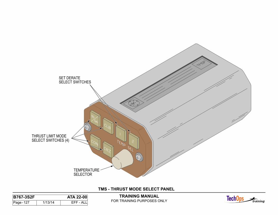
TRAINING MANUALFOR TRAINING PURPOSES ONLY
B767-3S2F ATA 22-00 Page - 127 1/13/14 EFF - ALL
THRUST LIMIT MODESELECT SWITCHES (4)
SELECTOR
SET DERATESELECT SWITCHES
TEMPERATURE
TMS - THRUST MODE SELECT PANEL
TRAINING MANUALFOR TRAINING PURPOSES ONLY
B767-3S2F ATA 22-00 Page - 128 1/13/14 EFF - ALL
TMS - OPERATION - EADI DISPLAYS
Autothrottle Modes
These are the operation modes that show:
- N1- SPD- FLCH- GA- IDLE- THR HOLD.
These are the limit modes that show:
- FLAP LIM- ALPHA- SPD LIM.
TEST shows for the MCDP ground test mode.
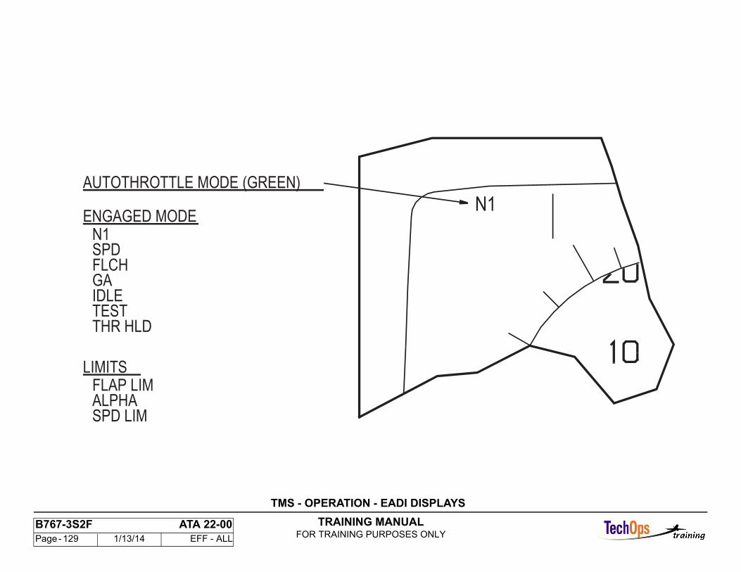
TRAINING MANUALFOR TRAINING PURPOSES ONLY
B767-3S2F ATA 22-00 Page - 129 1/13/14 EFF - ALL
AUTOTHROTTLE MODE (GREEN)
ENGAGED MODEN1SPDFLCHGAIDLETESTTHR HLD
LIMITSFLAP LIMALPHASPD LIM
N1
TMS - OPERATION - EADI DISPLAYS
TRAINING MANUALFOR TRAINING PURPOSES ONLY
B767-3S2F ATA 22-00 Page - 130 1/13/14 EFF - ALL
TMS - OPERATION - ENGINE EICAS DISPLAY - THRUST LIMIT FUNCTIONS
General
EICAS provides the displays for the TMC thrust limit functions.
Total Air Temperature and Selected Temperature Displays
Primary data source for total air temperature is the TMC. The ADC is the secondary data source. Source for selected temperature is the TMC digital databus. Assumed temperature is selected on the thrust mode select panel which goes the TMC.
Reference Thrust Mode
TO, GA, CON, CLB, CRZ, or MAN show in green for the mode. D-TO shows for assumed temperature derated takeoff mode. 1 or 2 follows the mode for other derated modes, white if preselected and green if active.
Manual Mode When the manual thrust set knob is pulled out, the reference thrust mode MAN is provided by the EICAS computer in green. The reference target cursors andreadouts are green and are controlled by the knob. Manual thrust limit is not used by the TMC.
Reference/Target Cursor and Reference Limit Display
When the manual thrust set knob is pushed in, the cursor primary data source is the FMC when VNAV is engaged (the cursor secondary data source is the TMC) and the reference limit display data source is the TMC. The cursor is magenta when controlled by the FMC and green when controlled by the TMC. The reference limit display is always green.
Maximum Limit Marker
The primary data source is the EEC. The TMC is the secondary data source and is used when the EEC data is invalid or the EEC ALTN light is on.
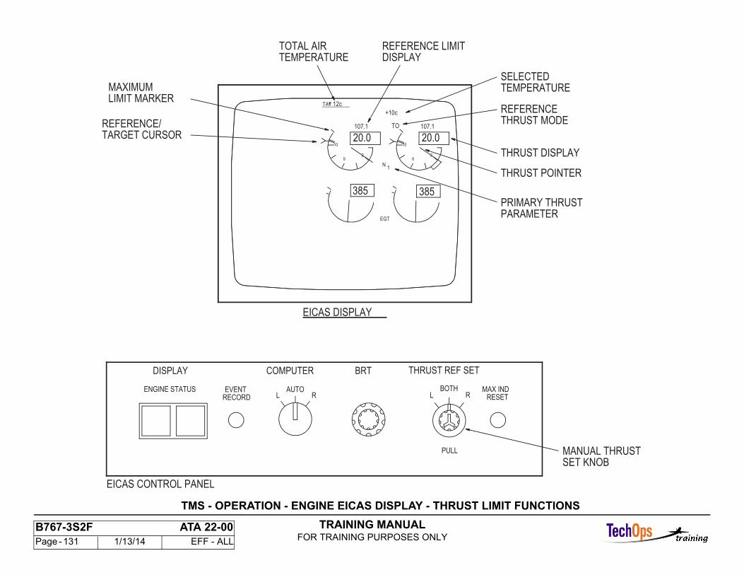
TRAINING MANUALFOR TRAINING PURPOSES ONLY
B767-3S2F ATA 22-00 Page - 131 1/13/14 EFF - ALL
DISPLAY
MAXIMUMLIMIT MARKER
TARGET CURSOR
TOTAL AIRTEMPERATURE
SELECTEDTEMPERATURE
REFERENCE LIMIT
EICAS DISPLAY
THRUST DISPLAY
THRUST POINTER
PRIMARY THRUSTPARAMETER
REFERENCE
REFERENCE/ THRUST MODE
TAT + 12c_________
+10c
20.0107.1
10
62
107.1
EGT
N1
20.010
62
385 385
TO
EICAS CONTROL PANEL
L R LBOTH
R
PULL
MAX INDRESET
EVENTRECORD
ENGINE STATUS AUTO
DISPLAY COMPUTER BRT THRUST REF SET
SET KNOBMANUAL THRUST
TMS - OPERATION - ENGINE EICAS DISPLAY - THRUST LIMIT FUNCTIONS
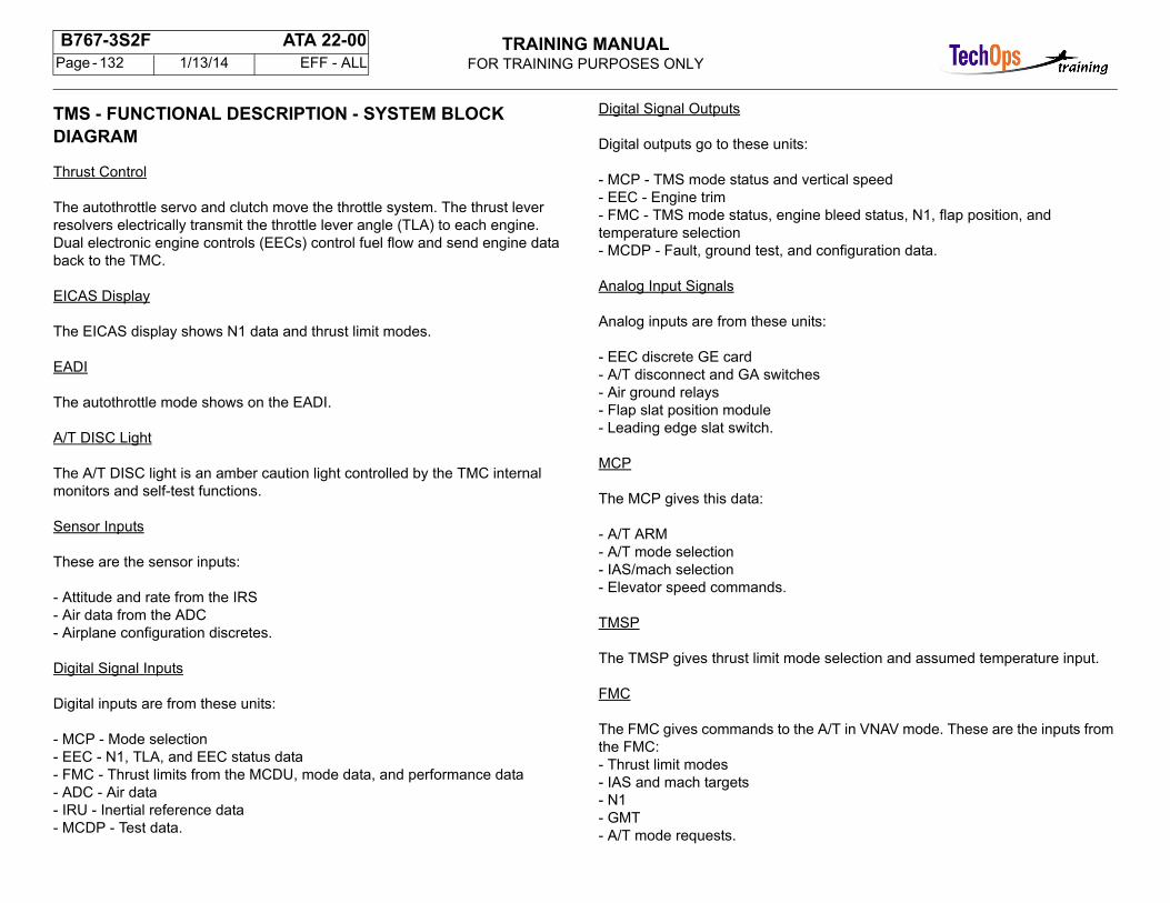
TRAINING MANUALFOR TRAINING PURPOSES ONLY
B767-3S2F ATA 22-00 Page - 132 1/13/14 EFF - ALL
TMS - FUNCTIONAL DESCRIPTION - SYSTEM BLOCKDIAGRAM
Thrust Control
The autothrottle servo and clutch move the throttle system. The thrust lever resolvers electrically transmit the throttle lever angle (TLA) to each engine.Dual electronic engine controls (EECs) control fuel flow and send engine data back to the TMC.
EICAS Display
The EICAS display shows N1 data and thrust limit modes.
EADI
The autothrottle mode shows on the EADI.
A/T DISC Light
The A/T DISC light is an amber caution light controlled by the TMC internal monitors and self-test functions.
Sensor Inputs
These are the sensor inputs:
- Attitude and rate from the IRS- Air data from the ADC- Airplane configuration discretes.
Digital Signal Inputs
Digital inputs are from these units:
- MCP - Mode selection- EEC - N1, TLA, and EEC status data- FMC - Thrust limits from the MCDU, mode data, and performance data- ADC - Air data- IRU - Inertial reference data- MCDP - Test data.
Digital Signal Outputs
Digital outputs go to these units:
- MCP - TMS mode status and vertical speed- EEC - Engine trim- FMC - TMS mode status, engine bleed status, N1, flap position, and temperature selection- MCDP - Fault, ground test, and configuration data.
Analog Input Signals
Analog inputs are from these units:
- EEC discrete GE card- A/T disconnect and GA switches- Air ground relays- Flap slat position module- Leading edge slat switch.
MCP
The MCP gives this data:
- A/T ARM- A/T mode selection- IAS/mach selection- Elevator speed commands.
TMSP
The TMSP gives thrust limit mode selection and assumed temperature input.
FMC
The FMC gives commands to the A/T in VNAV mode. These are the inputs from the FMC:- Thrust limit modes- IAS and mach targets- N1- GMT- A/T mode requests.
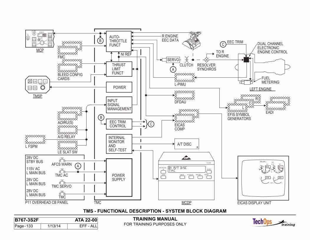
TRAINING MANUALFOR TRAINING PURPOSES ONLY
B767-3S2F ATA 22-00 Page - 133 1/13/14 EFF - ALL
DUAL CHANNEL
TMCP11 OVERHEAD CB PANEL
EEC TRIM
LE SLAT SW
R ENGINE
a
MCP
TMC
TMC AC
TMC SERVO
AFCS WARN
CLB
28V DC
1
TEMP SEL
2
CRZ
GATO
CON
A/G RELAY
A/T DISC
CLUTCH
28V DC
115V AC
SERVO
METERINGFUEL
ENGINE CONTROLELECTRONIC
RESOLVERSYNCHROS
EICAS DISPLAY UNIT
54.9 26.1
+38C
EGT
N1
48
12
318
96.1 D-TO 96.1
48
115.2
320
TAT + 12C
FMC
IRU(S)
28V DC
MCDP
TMSP
L FSPM
BLEED CONFIG
POWERSUPPLY
INPUTSIGNAL
AUTO-THROTTLEFUNCT
THRUSTLIMITFUNCT
POWER
EEC TRIMCONTROL
INTERNALMONITOR
SELF-TEST
EADI
GENERATORSEFIS SYMBOL
EICASCOMP
DFDAU
L-PIMU
TO RENGINE
AND
MANAGEMENT
NI REF
STBY BUS
L MAIN BUS
L MAIN BUS
L MAIN BUS
CARDS
EEC DATAC
LEFT ENGINE
GRD TEST SEL
ON/OFF FLT FAULTS GND TEST NO/SKIP
YES/ADV
COLLINS
UP
DOWN
C
B
B
A
CR
L
A
IAS
IAS/MACH
FL CH
V NAV
L NAV
SEL
OFF
A/T ARM
SPD
THR
OFF
F/DON
AD
TMS - FUNCTIONAL DESCRIPTION - SYSTEM BLOCK DIAGRAM
TRAINING MANUALFOR TRAINING PURPOSES ONLY
B767-3S2F ATA 22-00 Page - 134 1/13/14 EFF - ALL
TMS - FUNCTIONAL DESCRIPTION - SYSTEM BLOCK DIAGRAM CONT.
Autothrottle Functions
Thrust control uses N1. N1 protection uses the calculated N1 REF. MCP speed selection or the FMC controls speed. Rate of climb/descent is controlled in FL CH. The altitude change gives the vertical speed. Vertical speed is also controlled in GA. The throttlescome back to the aft stops in the flare mode.
EEC trim control gives trim signals to the selected EEC to decrease small differences in N1.
Thrust Limit Functions
The thrust limit section uses this data to calculate THRUST LIMIT REF and MAX N1:
- Engine type- Mode- Flight conditions- Aircraft configuration.
Input Signal Management
The input signal management gives signal source selection and validity monitor for the digital and analog input signals.
Internal Monitors and Self-Tests
The internal monitors and self-tests give disconnect logic. Recorded faults go to the MCDP.
BITE
BITE does ground tests requested by the MCDP and sends test results to the MCDP.
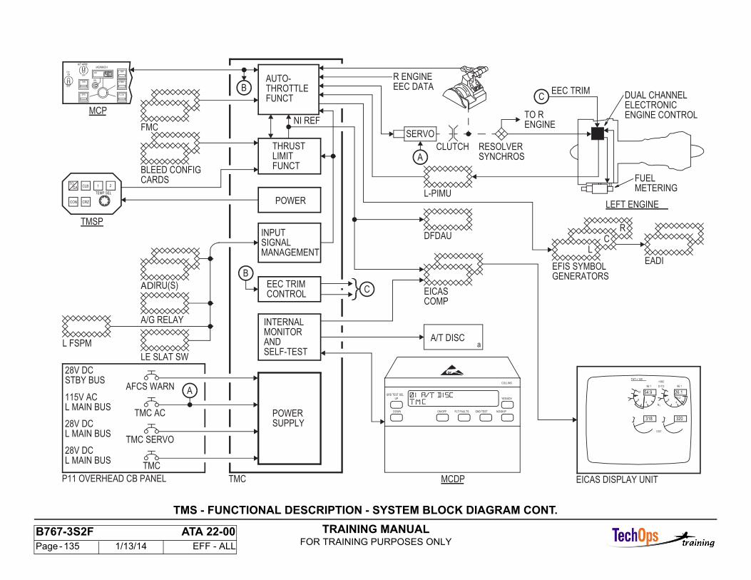
TRAINING MANUALFOR TRAINING PURPOSES ONLY
B767-3S2F ATA 22-00 Page - 135 1/13/14 EFF - ALL
TMS - FUNCTIONAL DESCRIPTION - SYSTEM BLOCK DIAGRAM CONT.
DUAL CHANNEL
TMCP11 OVERHEAD CB PANEL
EEC TRIM
LE SLAT SW
R ENGINE
a
MCP
TMC
TMC AC
TMC SERVO
AFCS WARN
CLB
28V DC
1
TEMP SEL
2
CRZ
GATO
CON
A/G RELAY
A/T DISC
CLUTCH
28V DC
115V AC
SERVO
METERINGFUEL
ENGINE CONTROLELECTRONIC
RESOLVERSYNCHROS
EICAS DISPLAY UNIT
54.9 26.1
+38C
EGT
N1
48
12
318
96.1 D-TO 96.1
48
115.2
320
TAT + 12C
FMC
IRU(S)
28V DC
MCDP
TMSP
L FSPM
BLEED CONFIG
POWERSUPPLY
INPUTSIGNAL
AUTO-THROTTLEFUNCT
THRUSTLIMITFUNCT
POWER
EEC TRIMCONTROL
INTERNALMONITOR
SELF-TEST
EADI
GENERATORSEFIS SYMBOL
EICASCOMP
DFDAU
L-PIMU
TO RENGINE
AND
MANAGEMENT
NI REF
STBY BUS
L MAIN BUS
L MAIN BUS
L MAIN BUS
CARDS
EEC DATAC
LEFT ENGINE
GRD TEST SEL
ON/OFF FLT FAULTS GND TEST NO/SKIP
YES/ADV
COLLINS
UP
DOWN
C
B
B
A
CR
L
A
IAS
IAS/MACH
FL CH
V NAV
L NAV
SEL
OFF
A/T ARM
SPD
THR
OFF
F/DON
AD
TRAINING MANUALFOR TRAINING PURPOSES ONLY
B767-3S2F ATA 22-00 Page - 136 1/13/14 EFF - ALL
MAINTENANCE FUNCTIONS
General
The following test numbers listed below can be run from the MaintenanceControl Display Panel.
Test 01 is the primary test for the FCC. Test 30 and 40 are required to performthe Autoland return to service test.
Note: Test 01 is part of test 40.
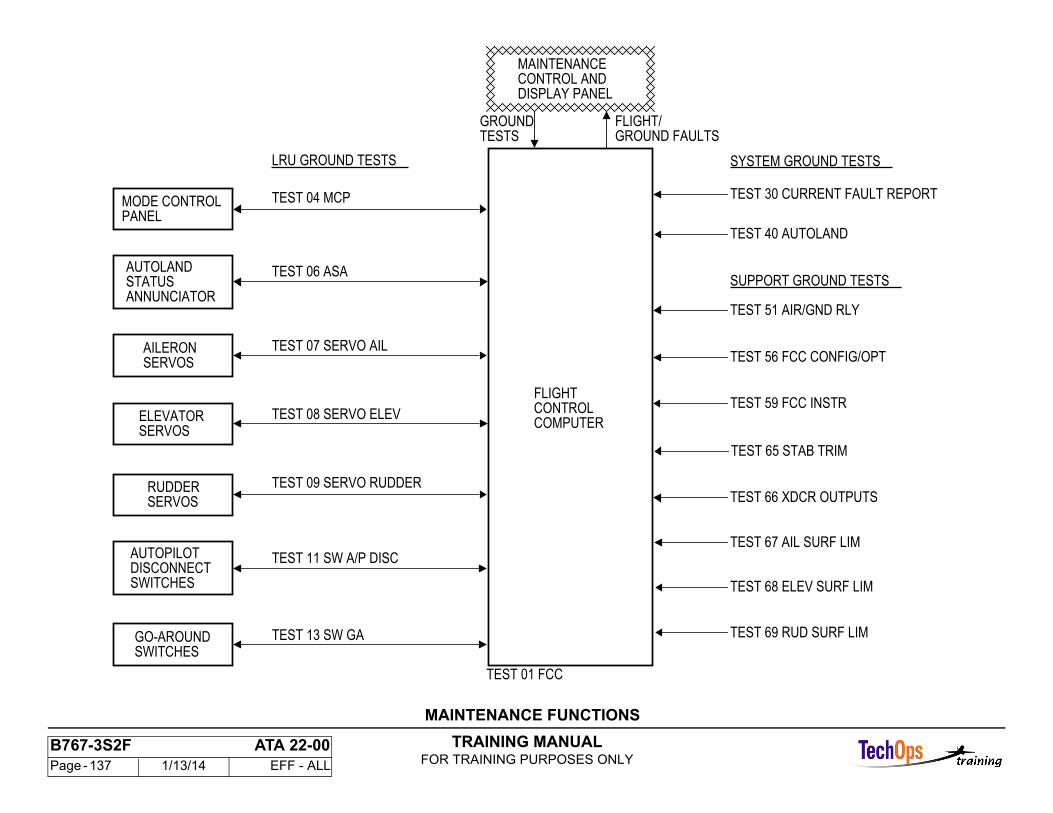
TRAINING MANUALFOR TRAINING PURPOSES ONLY
B767-3S2F ATA 22-00 Page - 137 1/13/14 EFF - ALL
LRU GROUND TESTS
SWITCHESGO-AROUND
TEST 09 SERVO RUDDER
TEST 07 SERVO AIL
TEST 06 ASA
TEST 04 MCP
SWITCHESDISCONNECTAUTOPILOT
SERVOSRUDDER
SERVOSELEVATOR
SERVOSAILERON
ANNUNCIATORSTATUSAUTOLAND
PANELMODE CONTROL
TEST 13 SW GA
TEST 11 SW A/P DISC
TEST 08 SERVO ELEV
SYSTEM GROUND TESTS
SUPPORT GROUND TESTS
TEST 30 CURRENT FAULT REPORT
TEST 40 AUTOLAND
TEST 51 AIR/GND RLY
TEST 56 FCC CONFIG/OPT
TEST 59 FCC INSTR
TEST 66 XDCR OUTPUTS
TEST 67 AIL SURF LIM
TEST 68 ELEV SURF LIM
TEST 69 RUD SURF LIM
TEST 01 FCC
GROUND FAULTSFLIGHT/GROUND
DISPLAY PANELCONTROL ANDMAINTENANCE
COMPUTERCONTROLFLIGHT
TESTS
TEST 65 STAB TRIM
MAINTENANCE FUNCTIONS
TRAINING MANUALFOR TRAINING PURPOSES ONLY
B767-3S2F ATA 22-00 Page - 138 1/13/14 EFF - ALL
MAINTENANCE MONITOR SYSTEM - REMOTE MCDPOPERATION
General
There are maintenance operations that can be done by one person with a remote MCDP control panel in the flight compartment. Annunciation is on the EICAS display. A hand-held, carry-on panel connects to a plug behind the P6 main power distribution panel. Open the panel to get access. There is a cutout for the cord.
Description
The remote panel provides the same switch functions as on the front of the MCDP. Mode annunciations and alphanumeric messages show on the EICAS display. Select the CONF/MCDP switch on the EICAS maintenance panel(P61) to show the MCDP display. The airplane must be on the ground to show the EICAS maintenance pages.
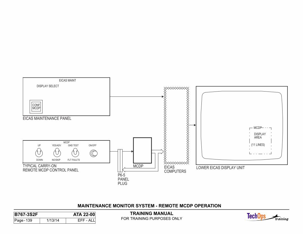
TRAINING MANUALFOR TRAINING PURPOSES ONLY
B767-3S2F ATA 22-00 Page - 139 1/13/14 EFF - ALL
EICASCOMPUTERS
MCDP LOWER EICAS DISPLAY UNIT
MCDP
DISPLAYAREA
(11 LINES)
PANELPLUG
P6-5
EICAS MAINTENANCE PANEL
TYPICAL CARRY-ONREMOTE MCDP CONTROL PANEL
NO/SKIP
UP
DOWN
MCDP
YES/ADV GND TEST
FLT FAULTS
ON/OFF
DISPLAY SELECT
EICAS MAINT
MCDPCONF
MAINTENANCE MONITOR SYSTEM - REMOTE MCDP OPERATION
TRAINING MANUALFOR TRAINING PURPOSES ONLY
B767-3S2F ATA 22-00 Page - 140 1/13/14 EFF - ALL
MAINTENANCE MONITOR SYSTEM - INTERFACE SYSTEMS
Primary Interface Systems
These are the primary interface systems:
- Flight control computers- Flight management computers- Thrust management computers- EICAS computers- Remote MCDP control panel- Air/Ground relays.The left, center, and right flight control computers use ARINC 429 data buses and analog discrete lines. Information includes ground test control and faultdata.
The left and right flight management computers use ARINC 429 data buses to send fault data. The thrust management computer uses ARINC 429 databuses and analog discrete lines. Information includes ground test control and fault data.
The EICAS computers and the MCDP remote control panel let flight compartment operation of the MCDP.
Secondary Interfaces
These components interface with the primary systems and may be tested from the MCDP:
- AFCS mode control panel (MCP)- Servos- Air Data/Inertial reference units (ADIRUs) - Thrust mode select panel (TMSP)- Throttle servo motor.
The mode control panel supplies control signals and gets status data from all six computers on ARINC 429 data buses.
Each flight control computer supplies analog control signals to its control surface servos and gets analog servo position signals.
Each flight control computer gets sensor data from its inertial reference unit and air data computer on ARINC 429 data buses.
The thrust management computer gets control signals from the thrust mode select panel on an ARINC 429 data bus.
The thrust management computer supplies analog control signals to the throttle servo motor and gets analog servo position signals.
Ground Test Interface
The primary systems are directly monitored by the MCDP. During the ground test, these systems interface with the secondary systems and various sensor/control inputs.
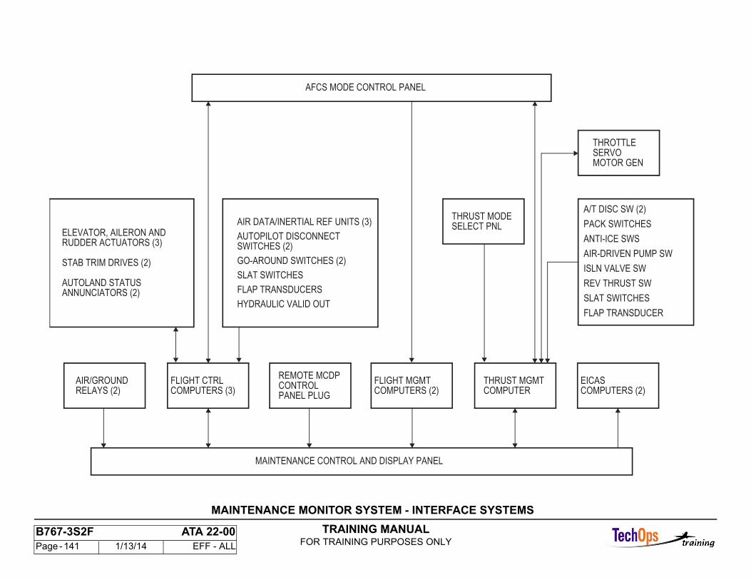
TRAINING MANUALFOR TRAINING PURPOSES ONLY
B767-3S2F ATA 22-00 Page - 141 1/13/14 EFF - ALL
AIR/GROUND
MAINTENANCE CONTROL AND DISPLAY PANEL
AFCS MODE CONTROL PANEL
RELAYS (2)
A/T DISC SW (2)
EICASCOMPUTERS (2)
FLIGHT CTRLCOMPUTERS (3)
REMOTE MCDPCONTROL
FLIGHT MGMTCOMPUTERS (2)
THRUST MGMTCOMPUTER
THRUST MODESELECT PNL
THROTTLESERVOMOTOR GEN
AIR DATA/INERTIAL REF UNITS (3)
AUTOPILOT DISCONNECTELEVATOR, AILERON AND
STAB TRIM DRIVES (2)
AUTOLAND STATUS
RUDDER ACTUATORS (3)
ANNUNCIATORS (2)
PACK SWITCHES
ANTI-ICE SWS
AIR-DRIVEN PUMP SW
ISLN VALVE SW
REV THRUST SW
PANEL PLUG
SWITCHES (2)
GO-AROUND SWITCHES (2)
SLAT SWITCHES
FLAP TRANSDUCERS
HYDRAULIC VALID OUTSLAT SWITCHES
FLAP TRANSDUCER
MAINTENANCE MONITOR SYSTEM - INTERFACE SYSTEMS
TRAINING MANUALFOR TRAINING PURPOSES ONLY
B767-3S2F ATA 22-00 Page - 142 1/13/14 EFF - ALL
MAINTENANCE MONITOR SYSTEM - INTERFACE SYSTEMS CONT.
Primary and Secondary Systems
Faults in these LRUs can be reported by the MCDP:
- FCC (3)- CDU (2)- FMC (2)- TMC- AIR/GND relays (2)- TMSP- MCP.
System Interface
The AFDS interfaces with these components:
- Flap position- Stab position- ASA indicators- A/P servos.
The FMCS interfaces with these components:
- Fuel flow indicator- Fuel quantity- Digital clock- EFIS control panel.
The TMS interfaces with these components:
- Control switches- Throttle Servo Motors- PLA transducer- FSEU- Flap POS- EEC.
These are ARINC 700 sensors:
- ILS- ADIRU- VOR- IRS- DME- Radar altimeter.
Faults in these LRUs/systems are not reported:
- Automatic direction finding (ADF) system- Communication radios- Air traffic control (ATC) system- Weather radar- Caution/warning system- Ground proximity warning system (GPWS)- M/ASI- Standby Altimeter- Yaw damper/YSM- Electronic flight instrument system (EFIS)- Vertical speed indicator (VSI)- RDMI.
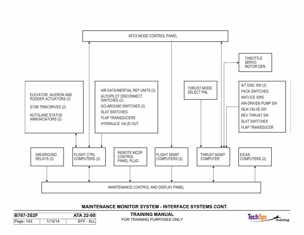
TRAINING MANUALFOR TRAINING PURPOSES ONLY
B767-3S2F ATA 22-00 Page - 143 1/13/14 EFF - ALL
MAINTENANCE MONITOR SYSTEM - INTERFACE SYSTEMS CONT.
AIR/GROUND
MAINTENANCE CONTROL AND DISPLAY PANEL
AFCS MODE CONTROL PANEL
RELAYS (2)
A/T DISC SW (2)
EICASCOMPUTERS (2)
FLIGHT CTRLCOMPUTERS (3)
REMOTE MCDPCONTROL
FLIGHT MGMTCOMPUTERS (2)
THRUST MGMTCOMPUTER
THRUST MODESELECT PNL
THROTTLESERVOMOTOR GEN
AIR DATA COMPUTERS (2)
AUTOPILOT DISCONNECTELEVATOR, AILERON AND
STAB TRIM DRIVES (2)
AUTOLAND STATUS
RUDDER ACTUATORS (3)
ANNUNCIATORS (2)
PACK SWITCHES
ANTI-ICE SWS
AIR-DRIVEN PUMP SW
ISLN VALVE SW
REV THRUST SW
PANEL PLUG
SWITCHES (2)
GO-AROUND SWITCHES (2)
SLAT SWITCHES
FLAP TRANSDUCERS
HYDRAULIC VALID OUTSLAT SWITCHES
FLAP TRANSDUCER
AIR/GROUND
MAINTENANCE CONTROL AND DISPLAY PANEL
AFCS MODE CONTROL PANEL
RELAYS (2)
A/T DISC SW (2)
EICASCOMPUTERS (2)
FLIGHT CTRLCOMPUTERS (3)
REMOTE MCDPCONTROL
FLIGHT MGMTCOMPUTERS (2)
THRUST MGMTCOMPUTER
THRUST MODESELECT PNL
THROTTLESERVOMOTOR GEN
AIR DATA/INERTIAL REF UNITS (3)
AUTOPILOT DISCONNECTELEVATOR, AILERON AND
STAB TRIM DRIVES (2)
AUTOLAND STATUS
RUDDER ACTUATORS (3)
ANNUNCIATORS (2)
PACK SWITCHES
ANTI-ICE SWS
AIR-DRIVEN PUMP SW
ISLN VALVE SW
REV THRUST SW
PANEL PLUG
SWITCHES (2)
GO-AROUND SWITCHES (2)
SLAT SWITCHES
FLAP TRANSDUCERS
HYDRAULIC VALID OUTSLAT SWITCHES
FLAP TRANSDUCER
TRAINING MANUALFOR TRAINING PURPOSES ONLY
B767-3S2F ATA 22-00 Page - 144 1/13/14 EFF - ALL
MAINTENANCE CONTROL AND DISPLAY PANEL
Purpose
The purpose of the MCDP is to get and store fault data from the flight management system computers and to initiate, select, and process ground test functions.
Power Required
The MCDP uses 115v ac, 400 Hz, single-phase power.
Physical Features
The MCDP is a 6 MCU.
The weight is 15 pounds.
The MCDP uses main equipment center rack air for cooling.
Front Panel Features - Display Window
The MCDP display has two lines of data with 16 characters on each line. Each character contains 17 segment gas discharge lamps, including decimal point.All displays are in the English language.
Control Switches - ON/OFF
The MCDP ON/OFF switch is a momentary red switch/light with black letters (FAIL). The lamp is replaceable from the front panel. It starts a power-up routine in the central processing unit (CPU). The power-up routine turns on the switch/light. The switch/light goes off and the FAIL message is removed after five seconds if the MCDP passes the self-test.
MODE SWITCHES
The MCDP flight faults mode select switch is a momentary switch/light with a lamp replaceable from the front panel. It comes on white when engaged andcommands the CPU to enter the last flight faults routine.
The MCDP ground test mode select switch is a momentary switch/light with a lamp replaceable from the front panel. It comes on white when engaged and commands the CPU to enter the ground test routine.
GND TEST SEL UP Switch
The ground test select up switch does not have a light. It moves test numbers up one number each time it is pushed. When you hold the switch in, it slews the test numbers up at the rate of five numbers per second.
GRD TEST SEL DOWN Switch
The ground test select down switch does not have a light. It moves the test numbers down one number each time it is pushed. When you hold the switch in, it slews the test numbers down at the rate of five numbers per second.
YES/ADV Operation Switch The yes/advance switch does not have a light. It is used by the operator to respond to interrogative messages in the flight fault mode and the ground testmode.
NO/SKIP Operation Switch
The no/skip switch does not have a light. It is used by the operator to respond to interrogative messages in the flight fault mode and the ground test mode.
Operating Instruction Plate
The instruction panel is on the left side of the front panel. It contains instructions for these functions:
- Apply power and initialize unit- Select mode of operation- Respond to interrogative messages- Ground test operation.
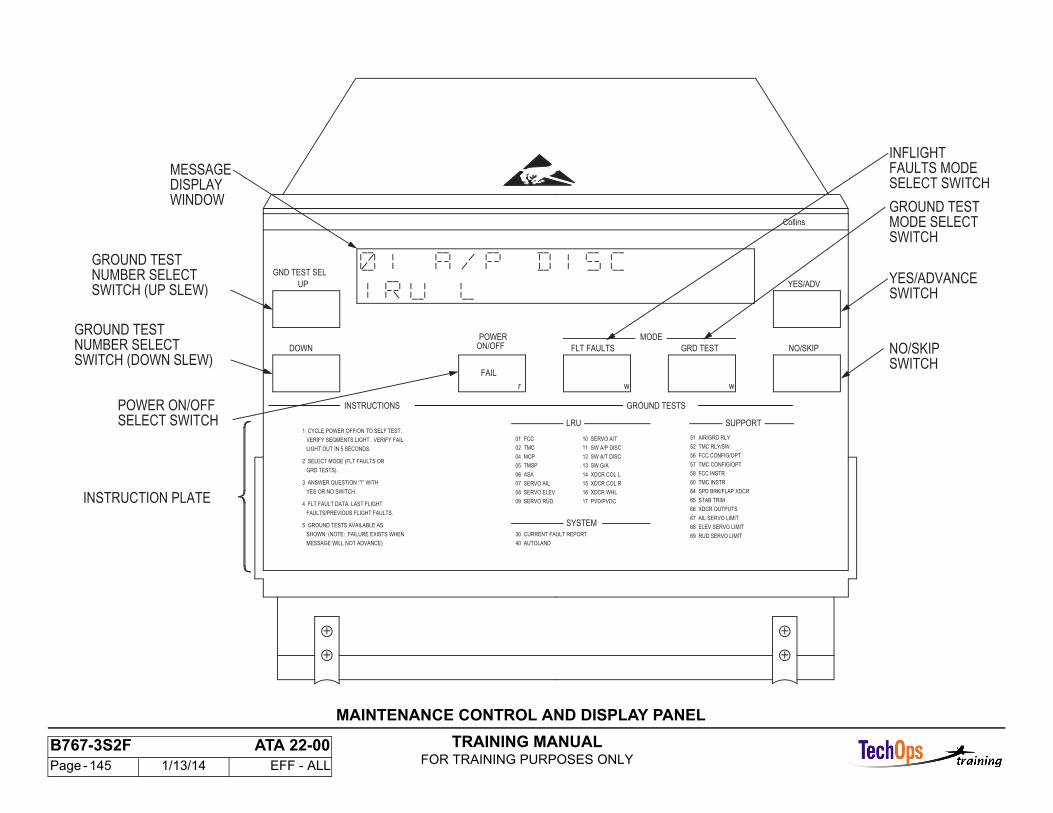
TRAINING MANUALFOR TRAINING PURPOSES ONLY
B767-3S2F ATA 22-00 Page - 145 1/13/14 EFF - ALL
GROUND TEST
17 PVD/PVDC
16 XDCR WHL
15 XDCR COL R
NO/SKIP
YES/ADVANCE
INSTRUCTION PLATE
MESSAGE
SELECT SWITCH
SWITCH (DOWN SLEW)
SWITCH (UP SLEW)
05 TMSP
MODE
wwr
FAIL
POWER
GND TEST SEL
64 SPD BRK/FLAP XDCR
57 TMC CONFIG/OPT
VERIFY SEGMENTS LIGHT. VERIFY FAIL
4 FLT FAULT DATA: LAST FLIGHT
INFLIGHT
SWITCHMODE SELECTGROUND TEST
FAULTS MODE
WINDOW
NUMBER SELECT
NUMBER SELECTGROUND TEST
POWER ON/OFF
69 RUD SERVO LIMIT
68 ELEV SERVO LIMIT
67 AIL SERVO LIMIT
66 XDCR OUTPUTS
65 STAB TRIM
60 TMC INSTR
59 FCC INSTR
09 SERVO RUD
08 SERVO ELEV
07 SERVO AIL
06 ASA
MESSAGE WILL NOT ADVANCE)
SHOWN: (NOTE: FAILURE EXISTS WHEN
FAULTS/PREVIOUS FLIGHT FAULTS.
YES OR NO SWITCH.
3 ANSWER QUESTION “?” WITH
GRD TESTS).
LIGHT OUT IN 5 SECONDS.
1 CYCLE POWER OFF/ON TO SELF TEST.SUPPORT
SYSTEM
56 FCC CONFIG/OPT
52 TMC RLY/SW
51 AIR/GRD RLY
40 AUTOLAND
30 CURRENT FAULT REPORT
14 XDCR COL L
13 SW G/A
12 SW A/T DISC
11 SW A/P DISC
10 SERVO A/T
04 MCP
02 TMC
01 FCC
5 GROUND TESTS AVAILABLE AS
2 SELECT MODE (FLT FAULTS OR
LRU
GROUND TESTSINSTRUCTIONS
NO/SKIP
YES/ADV
GRD TESTFLT FAULTSON/OFFDOWN
UP
Collins
DISPLAY SELECT SWITCH
SWITCH
SWITCH
MAINTENANCE CONTROL AND DISPLAY PANEL
TRAINING MANUALFOR TRAINING PURPOSES ONLY
B767-3S2F ATA 22-00 Page - 146 1/13/14 EFF - ALL
MAINTENANCE CONTROL AND DISPLAY PANEL CONT.
Ground Test Listing
The list of ground tests is on the right side of the front panel. It contains test numbers and names for the LRU, SYSTEM, and SUPPORT tests that the operator can select.
Internal Circuits - Power
The power supply provides internal DC power. It contains +5v dc keep alive power during dormant periods when the airplane is in the air.
I/O Buses
The MCDP gets information from the three flight control computers (FCC), 2 flight management computers (FMC), and the thrust management computer on digital ARINC 429 receivers. It sends information to the same computerson ARINC 429 transmitters.
Analog Discrete
Analog discrete output buffer circuits supply four computers with analog ground test discrete signals.
Software - Executive
The computer software program organization is controlled by an executive routine that manages these routines:
- Power-up- Power interruptions- Mode change- Periodic functions- Power down.
Mode Change Routine
A mode change routine controls these functions:
- Auto on- Power up self-test- Flight faults- ground test routines.
Fault Monitor
Fault monitor occurs during the power-up self-test.
Fault Memory
The flight faults are stored in an EPROM nonvolatile memory. The memory can be cleared in the shop with ITS test equipment.
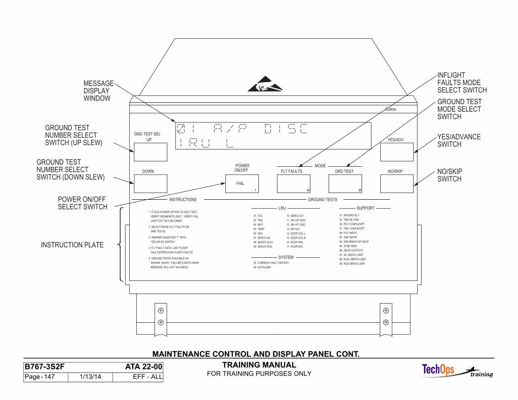
TRAINING MANUALFOR TRAINING PURPOSES ONLY
B767-3S2F ATA 22-00 Page - 147 1/13/14 EFF - ALL
MAINTENANCE CONTROL AND DISPLAY PANEL CONT.
GROUND TEST
17 PVD/PVDC
16 XDCR WHL
15 XDCR COL R
NO/SKIP
YES/ADVANCE
INSTRUCTION PLATE
MESSAGE
SELECT SWITCH
SWITCH (DOWN SLEW)
SWITCH (UP SLEW)
05 TMSP
MODE
wwr
FAIL
POWER
GND TEST SEL
64 SPD BRK/FLAP XDCR
57 TMC CONFIG/OPT
VERIFY SEGMENTS LIGHT. VERIFY FAIL
4 FLT FAULT DATA: LAST FLIGHT
INFLIGHT
SWITCHMODE SELECTGROUND TEST
FAULTS MODE
WINDOW
NUMBER SELECT
NUMBER SELECTGROUND TEST
POWER ON/OFF
69 RUD SERVO LIMIT
68 ELEV SERVO LIMIT
67 AIL SERVO LIMIT
66 XDCR OUTPUTS
65 STAB TRIM
60 TMC INSTR
59 FCC INSTR
09 SERVO RUD
08 SERVO ELEV
07 SERVO AIL
06 ASA
MESSAGE WILL NOT ADVANCE)
SHOWN: (NOTE: FAILURE EXISTS WHEN
FAULTS/PREVIOUS FLIGHT FAULTS.
YES OR NO SWITCH.
3 ANSWER QUESTION “?” WITH
GRD TESTS).
LIGHT OUT IN 5 SECONDS.
1 CYCLE POWER OFF/ON TO SELF TEST.SUPPORT
SYSTEM
56 FCC CONFIG/OPT
52 TMC RLY/SW
51 AIR/GRD RLY
40 AUTOLAND
30 CURRENT FAULT REPORT
14 XDCR COL L
13 SW G/A
12 SW A/T DISC
11 SW A/P DISC
10 SERVO A/T
04 MCP
02 TMC
01 FCC
5 GROUND TESTS AVAILABLE AS
2 SELECT MODE (FLT FAULTS OR
LRU
GROUND TESTSINSTRUCTIONS
NO/SKIP
YES/ADV
GRD TESTFLT FAULTSON/OFFDOWN
UP
Collins
DISPLAY SELECT SWITCH
SWITCH
SWITCH
TRAINING MANUALFOR TRAINING PURPOSES ONLY
B767-3S2F ATA 22-00 Page - 148 1/13/14 EFF - ALL
MAINTENANCE MONITOR SYSTEM - COMPONENT LOCATION
Maintenance Monitor System Component Location
The MCDP is on the E1-2 shelf in the main equipmentcenter.
The portable remote panel connector is in the P6 panelbehind or below the circuit breaker door panel.
When selected, the MCDP output shows in the MCDPdisplay area of the lower EICAS display.
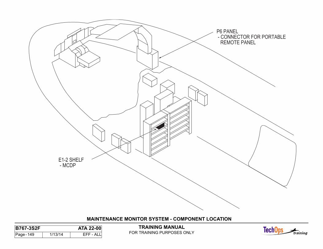
TRAINING MANUALFOR TRAINING PURPOSES ONLY
B767-3S2F ATA 22-00 Page - 149 1/13/14 EFF - ALL
P6 PANEL - CONNECTOR FOR PORTABLE REMOTE PANEL
E1-2 SHELF - MCDP
MAINTENANCE MONITOR SYSTEM - COMPONENT LOCATION
TRAINING MANUALFOR TRAINING PURPOSES ONLY
B767-3S2F ATA 22-00 Page - 150 1/13/14 EFF - ALL
REMOTE MCDP CONTROL PANEL CONNECTOR LOCATION
Purpose
The remote MCDP control panel connector gives theconnection for a carry-on remote MCDP control panel.
The panel is for ground maintenance only and lets youoperate the MCDP from the flight compartment.
Connector Location
The connector is in the P6 part of the main powerdistribution panel.
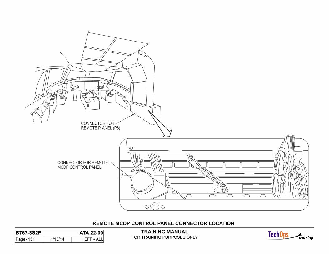
TRAINING MANUALFOR TRAINING PURPOSES ONLY
B767-3S2F ATA 22-00 Page - 151 1/13/14 EFF - ALL
MCDP CONTROL PANELCONNECTOR FOR REMOTE
REMOTE P ANEL (P6)CONNECTOR FOR
REMOTE MCDP CONTROL PANEL CONNECTOR LOCATION
TRAINING MANUALFOR TRAINING PURPOSES ONLY
B767-3S2F ATA 22-00 Page - 152 1/13/14 EFF - ALL
LRU FAULT CONSOLIDATION
Purpose
One of the advanced features available with a system level maintenance conceptis fault consolidation, where a failure indication may be examined on a systembasis to determine if a sensor or a wiring interface has failed.
LRU Failure
The upper diagram illustrates a failure case of the right inertial reference unitwhich is isolated via the indicated logic equation.
Interface Failure
In the lower diagram, a wiring fault is indicated where the input to the FCC Rhas been interrupted. By examining the condemnation status on a systembasis, the interface between the right IRU and FCC R is identified as faulty. Thiswill require deferred maintenance action but prevents the erroneous removal ofeither the inertial reference unit or the right flight control computer.
Message Format
These fault consolidation routines are used to determine the bottom line portionof flight fault messages.
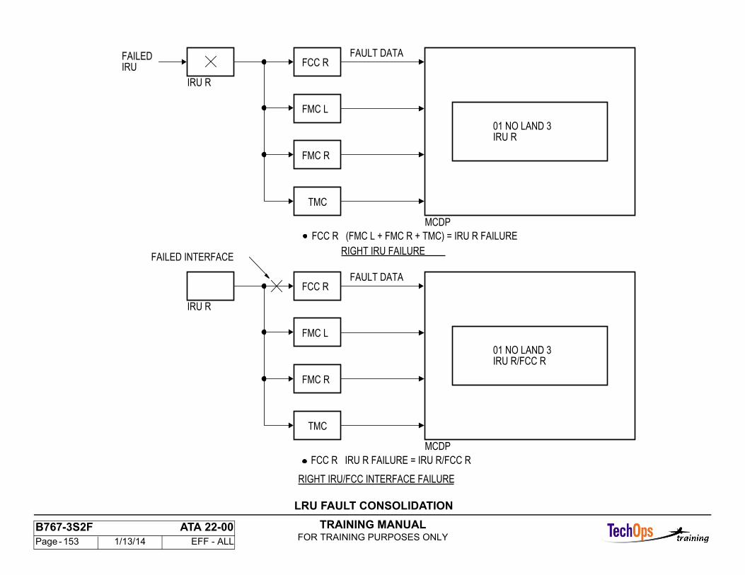
TRAINING MANUALFOR TRAINING PURPOSES ONLY
B767-3S2F ATA 22-00 Page - 153 1/13/14 EFF - ALL
FMC L
FMC R
TMC
FAULT DATA
01 NO LAND 3IRU R
MCDP
RIGHT IRU FAILURE
IRU R
FCC RFAILEDIRU
FCC R IRU R FAILURE = IRU R/FCC R
RIGHT IRU/FCC INTERFACE FAILURE
FCC R (FMC L + FMC R + TMC) = IRU R FAILURE
FAILED INTERFACE
FMC L
FMC R
TMC
FAULT DATA
01 NO LAND 3IRU R/FCC R
MCDP
IRU R
FCC R
LRU FAULT CONSOLIDATION
TRAINING MANUALFOR TRAINING PURPOSES ONLY
B767-3S2F ATA 22-00 Page - 154 1/13/14 EFF - ALL
FAULT MESSAGE FORMATS
FLIGHT FAULT MESSAGE FORMAT
Historical Flight Tag and Fault Storage
The historical flight tag (HFT) is incremented during AUTO POWER ON if, andonly if, the MCDP receives a STORE DATA Bit from one or more FCCs, FMCsand TMC. The STORE DATA Bit is transmitted by one of these computers onlywhen the following sequence of events has occurred: IRS ground speed 100KNTS and air/ground = in air, THEN IRS ground speed 40 KNTS and air ground= on ground ,Additionally, an engaged FCC channel will delay setting itsSTORE DATA bit until the channel is disengaged.
Number Allocation
The historical flight tag is defined as follows: 00 PRESENT FLT FAULTS - 01LAST FLT FAULTS - 02-99 PREVIOUS FLT FAULTS
Faulty LRU
The bottom line of the MCDP flight fault message is the faulty LRU or group ofLRU's. The fault information provided on the bottom line of the display shouldbe sufficient for most unscheduled maintenance activities. A faulty LRU groupmessage consists of two LRU's with a slash between. The slash mark indicateswiring may be at fault. The group message is used when the fault can not bedefinitely isolated.
DIAGNOSTIC CODES - FORMAT
Description
The MCDP decodes diagnostic fault data received from the FCC, FMC andTMC computers and provides for a display of a diagnostic message in theshown format.Flight Fault Diagnostics
The diagnostic is displayed in the flight faults mode by pushing the FLT FAULTSswitch when an LRU fault is being displayed.
Ground Test Diagnostics
The diagnostic is displayed in the ground test mode (Test 30 CURRENT FAULTREPORT only) by pushing the GRD TEST switch when an LRU fault is beingdisplayed.
Content
The diagnostic code defines the monitor within a computer that tripped to produce the displayed flight deck effect and faulty LRU. The decimal codes andtheir related monitors are defined in the following tables. An intermittent fault is defined as a fault that sometime in the past, during flight, caused a monitor to trip, but at some later time during the flight did not. No intermittent bit is present for ground test diagnostics.
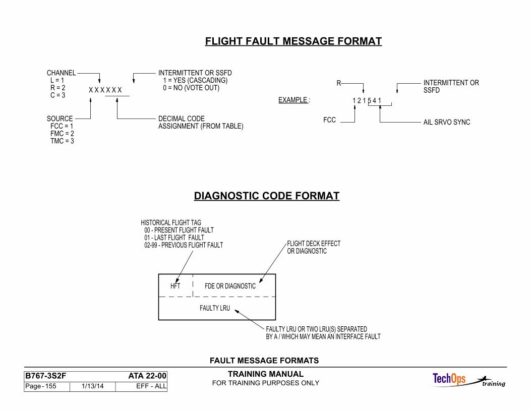
TRAINING MANUALFOR TRAINING PURPOSES ONLY
B767-3S2F ATA 22-00 Page - 155 1/13/14 EFF - ALL
X X X X X X
ASSIGNMENT (FROM TABLE)DECIMAL CODE
0 = NO (VOTE OUT)1 = YES (CASCADING)
INTERMITTENT OR SSFD
TMC = 3FMC = 2FCC = 1
SOURCE
C = 3R = 2L = 1
CHANNEL
1 2 1 5 4 1
INTERMITTENT OR
AIL SRVO SYNCFCC
R
EXAMPLE :
SSFD
FLIGHT FAULT MESSAGE FORMAT
BY A / WHICH MAY MEAN AN INTERFACE FAULTFAULTY LRU OR TWO LRU(S) SEPARATED
OR DIAGNOSTICFLIGHT DECK EFFECT
FAULTY LRU
FDE OR DIAGNOSTICHFT
02-99 - PREVIOUS FLIGHT FAULT01 - LAST FLIGHT FAULT00 - PRESENT FLIGHT FAULT
HISTORICAL FLIGHT TAG
DIAGNOSTIC CODE FORMAT
FAULT MESSAGE FORMATS
Recommended